

Siemens FDCW221, SMF6120, SMF121, DOW1171 Technical Manual
FDCW221, DOW1171,
Building Technologies
SMF121, SMF6120
Radio gateway, radio smoke detector,
manual call point, radio base
Technica l Manual
009865_m_en_-2015-11-06 Control Products and Systems

Legal notice
Building Technologies
009865_m_en_
--
Fire Safety
Legal notice
Technical specifications and availability subject to change without notice.
Transmitt al, reproduction, dissemination and/or editing of this document as well as
utilization of its contents and communication thereof to others without express
authorization are prohibited. Offenders will be held liable for payment of damages.
All rights creat ed by patent grant or registration of a utility model or design patent
are reserved.
Issued by:
Siemens Switzerland Ltd.
Building Technologies Div ision
International Headquarters
Gubelstrasse 22
CH-6301 Zug
Tel. +41 41 724-2424
www.siemens.com/buildingtechnologies
Edition: 2015-11-06
Document ID: 009865_m_en_--
© Siemens Switzerland Lt d, 2007
2 | 82
2015-11-06

Building Technologies
009865_m_en_
--
Table of contents
1 Ab ou t thi s doc um e nt ............................................................................. 7
1.1 Applicable documents ................................................................................. 9
1.2 Download center ......................................................................................... 9
1.3 Technical terms .........................................................................................10
1.4 Revision history .........................................................................................11
2 Sa fet y ............................................................................................... 1 3
2.1 Safety instructions .....................................................................................13
2.2 Safety regulations for the method of operation ...........................................15
2.3 Standards and directives complied with......................................................17
2.4 Release Notes ...........................................................................................17
3 Str u ct ur e an d fun c ti o n ......................................................................... 18
3.1 Structure of the radio gateway FDCW221 ..................................................20
3.1.1 Overvie w ....................................................................................20
3.1.2 Internal view ...............................................................................21
3.1.3 Connections ................................................................................22
3.1.4 Radio transmission .....................................................................22
3.1.5 Reed con ta ct and bu tto n .............................................................23
3.1.6 Scope of del i very ........................................................................23
3.2 Structure of the radio smoke detector DOW1171 .......................................24
3.2.1 Parame te r sets for th e radio s moke dete ctor DOW1171 ..............26
3.2.2 Scope of del i very ........................................................................26
3.3 Structure of the manual call point SMF121 and radio base SM F6120 ... ...... 27
3.3.1 Scope of del i very ........................................................................27
3.4 Product version ES ....................................................................................28
3.5 Details for ordering ....................................................................................29
3.6 RadioSpy ...................................................................................................29
3.7 Accessories for the FDCW221 radio gateway ............................................30
3.7.1 9 V lithium mangan e se dioxide battery ........................................30
3.7.2 Micro terminal DBZ11 90-AA ........................................................30
3.7.3 Conne ction terminal DBZ1190-A B ...............................................30
3.7.4 MCL-USB adapter FDUZ221.......................................................30
3.7.5 Radio test se t DZ W1 17 1 .............................................................31
3.7.6 RadioSpy ....................................................................................31
3.7.7 Cable ties 2.4 x 137 ....................................................................31
3.8 Accessories for radio smoke detector DOW1171 .......................................32
3.8.1 DBW117 1 base ...........................................................................32
3.8.2 9 V lithium mangan e se dioxide battery ........................................32
3.8.3 DBZ119 0 dete cto r locki ng de vi ce ................................................32
3.8.4 Base attachme n t , surfa ce-mounte d, humi d DBZ1 1 92 ..................3 2
3.8.5 Protecti ve cage DBZ1194 ...........................................................33
3.8.6 Desig na ti on pl a te DBZ1 19 3 A ......................................................33
Fire Safety
3 | 82
2015-11-06

Building Technologies
009865_m_en_
--
Fire Safety
3.9 Accessories for manual call point SMF121 wit h radio base SMF6120 ....... . 34
3.9.1 3.6 V lithium batte ry .................................................................... 34
3.9.2 Key ............................................................................................. 34
3.9.3 Glass insert ................................................................................. 34
3.10 Function .................................................................................................... 35
3.10.1 Radio gateway FDCW221 diagnosis levels ................................. 36
3.10.2 Behavior in degraded mode ........................................................ 37
3.10.3 Operation modes of the radio gateway ........................................ 37
3.10.3.1 Normal operation ......................................................... 37
3.10.3.2 Start-up operation ........................................................ 37
3.10.3.3 Configuration operation ................................................ 37
3.10.4 Line separator in the radio gateway FDCW221 ........................... 38
3.10.5 Status display on the radio gateway FDCW221 ........................... 39
3.10.6 Status display on the radio smoke detector DOW1171
and on the radio base SMF6120 ................................................. 41
3.10.7 Power supply .............................................................................. 42
4 Planning ............................................................................................43
4.1 Compatibility .............................................................................................. 43
4.2 Usage conditions ....................................................................................... 44
4.2.1 Enviro nmental influe nces ............................................................ 44
4.3 Transmission field ...................................................................................... 45
4.4 Defining the place of mounting ................................................................... 47
4.5 Radio test set DZW1171 ............................................................................ 47
5 Mounting/Installation ...........................................................................48
5.1 Installing and connecting the radio gateway FDCW221 .............................. 48
5.2 Installing the radio smoke detector DOW1171............................................ 50
5.3 Installing the radio base SMF6120 and manual call point SMF121 ........ ..... 53
6 Com miss ioni ng ...................................................................................5 7
6.1 Basic rules for commissioning .................................................................... 57
6.2 Starting up the radio gateway .................................................................... 58
6.3 Logging radio detectors on to the radio gateway ........................................ 59
6.4 Starting up the radio gateway on the detector line ...................................... 60
6.5 Logging radio detectors off the radio gateway ............................................ 61
6.6 Resetting the radio gateway to delivery status............................................ 62
6.7 Resetting the DOW1171 to delivery status ................................................. 63
6.8 Resetting the SMF6120 to delivery status .................................................. 65
4 | 82
2015-11-06

Building Technologies
009865_m_en_
--
7 Mai nte n a n c e / t r o u b le s h oo t i n g ............................................................. 67
7.1 Changing batteries on the FDCW221 .........................................................67
7.2 Changing batteries on the DOW1171 .........................................................68
7.3 Changing batteries on the SMF6120 ..........................................................69
7.4 Status query ..............................................................................................70
7.5 Performance check ....................................................................................70
7.6 Remedying faults .......................................................................................70
7.7 Replace radio gateway ..............................................................................71
7.8 Replacing radio detectors ..........................................................................71
7.9 Replacing the glass plate on the manual call point SMF121 .......................72
7.10 Updating the firmware of radio gateway FDCW221 ....................................73
8 Specifications ..................................................................................... 74
8.1 Technical data for the radio gateway FDCW221.........................................74
8.2 Technical data for radio smoke detector DOW1171....................................76
8.3 Technical data f or manual call point SMF121 and radio base SMF 6120 . ....77
8.4 Dimensions................................................................................................78
8.5 Environmental compatibility and disposal ...................................................79
Index ........................................................................................................ 80
Fire Safety
5 | 82
2015-11-06

Building Technologies
009865_m_en_
--
Fire Safety
6 | 82
2015-11-06
About this document
Applicable documents
82
009865_m_en_
--
Fire Safety
1 About this document
The SMF6120 radio base may only be used as a replacement device in fire
Goal and purpose
This document describes the devices
● Radio gateway FDCW221
● DOW1171 radio smoke detector
● Manual call point SMF 121
● Radio base SMF6120
and how to integrate the devices into the fire detection system FDnet.
It contains all the inf ormation you'll need about set up, funct ions, planning,
mounting, and commis sioning.
detection inst allations that were inst alled prior to April 1, 2011!
Target groups
The information in this document is intended for the following target groups:
1
Target group Activity Qualificatio n
Product Manager
● Is responsible for information
passing between the manuf acturer
and regional company.
● Coordinates the flow of information
between the individual groups of
● Has obtained suitable specialist
training for the function and for the
products.
● Has attended the training courses
for Product Managers.
people involved in a project.
Project Manager
Project engineer
● Coordinates the deploym ent of all
persons and resources involved in
the project according to schedule.
● Provides the information required to
run the project.
● Sets parameters for product
depending on specific national
and/or customer requirements.
● Checks operability and appr oves
the product for commissioning at the
● Has obtained suitable specialist
training for the function and for the
products.
● Has attended the training courses
for Project Managers.
● Has obtained suitable specialist
training for the function and for the
products.
● Has attended the training courses
for Product Engineer.
place of installation.
● Is responsible for troubleshooting.
Installation pers onnel
● Assembles and installs the product
components at the place of
installation.
● Has received specialist training in
the area of building installation
technology or electrical installations.
● Carries out a performance check
following installation.
Maintenance personnel ● Carries out all maint enance work.
● Checks that the products are in
perfect working order.
● Searches for and corrects
malfunctions.
Building Technologies
● Has obtained suitable specialist
training for the function and for the
products.
7 |
2015-11-06
About this document
Applicable documents
1
Building Technologies
009865_m_en_
--
Fire Safety
The 'i'
symbol identifies supplementary information and tips for an easier way of
Source language and reference document
● The source/original language of this document is German (de).
● The reference version of this document is the international version in English.
The international ver sion is not localized.
Document identification
The document ID is structured as follows:
ID code Examples
ID_Modificat ionIndex_Language_COUN
TRY
-- = multilingual or international
A6V10215123_a_de_DE
A6V10215123_a_en_-A6V10315123_a_--_--
Date format
The date format in the document corresponds to the recommendation of
international standard ISO 8601 (format YYYY-MM-DD).
Conventions for text marking
Markups
Special markups are shown in this document as follows:
⊳ Requirement for a behavior instruction
1.
2.
– Version, option, or detailed informat ion for a behavior instruction
⇨ Intermediate result of a behavior instruction
⇨ End result of a behavior instruction
●
Behavior instruction with at least two operation sequences
Numbered lists and behavior instructions with an operation
sequence
[➙ X] Reference to a page number
'Text' Quotation, reproduced identically
<Key> Identificat ion of keys
>
Relation sign and for ident ification between steps in a sequence,
e.g., 'Menu bar' > ' Help' > 'Help topics'
↑ Te xt Identif ication of a glossary entry
Supplementary information and tips
working.
8 | 82
2015-11-06
About this document
Applica
ble documents
82
009865_m_en_
--
Fire Safety
1.1 Applicable documents
You will also find
information about search variants and links to mobile
Docu ment ID Title
004446 Operation instructions Radio test set DZW1171
007227 Technical manual D etector ex changer and tester FDUD292
008250 Technical Manual Line tester FDUL221
008331 List of compatibility (for 'Sinteso™' product line)
009052
009718 Technical Manual I ntellige nt detector t ester FDUD 293
009854 Installation MCL-USB Adapter FDUZ221
010087
A6V10200368 Install ation Radio base SMF6120, Manual call point SMF121
A6V10217915 Installation RadioSpy
A6V10229812 User-Manual RadioSpy
A6V10336734 Installation Radio gateway FDCW221
A6V10336739 Installation Radio smoke, detector Base DOW1171, DBW1171
FS20 Fire detection system - Commissioning, Maintenance,
Troubleshooting
Data sheet Radio fire detection system FDCW221, DOW1171,
SMF6120, SMF121
1
1.2 Download center
You can download various types of documents, such as data sheets, installation
instructions, and license texts via the following Internet address :
http://siemens.com/bt/download
l Enter t he document ID in the 'Find by keyword' input box.
applications (apps) for various systems on the home page.
Building Technologies
9 |
2015-11-06

About this document
Technical terms
1
Building Technologies
009865_m_en_
--
Fire Safety
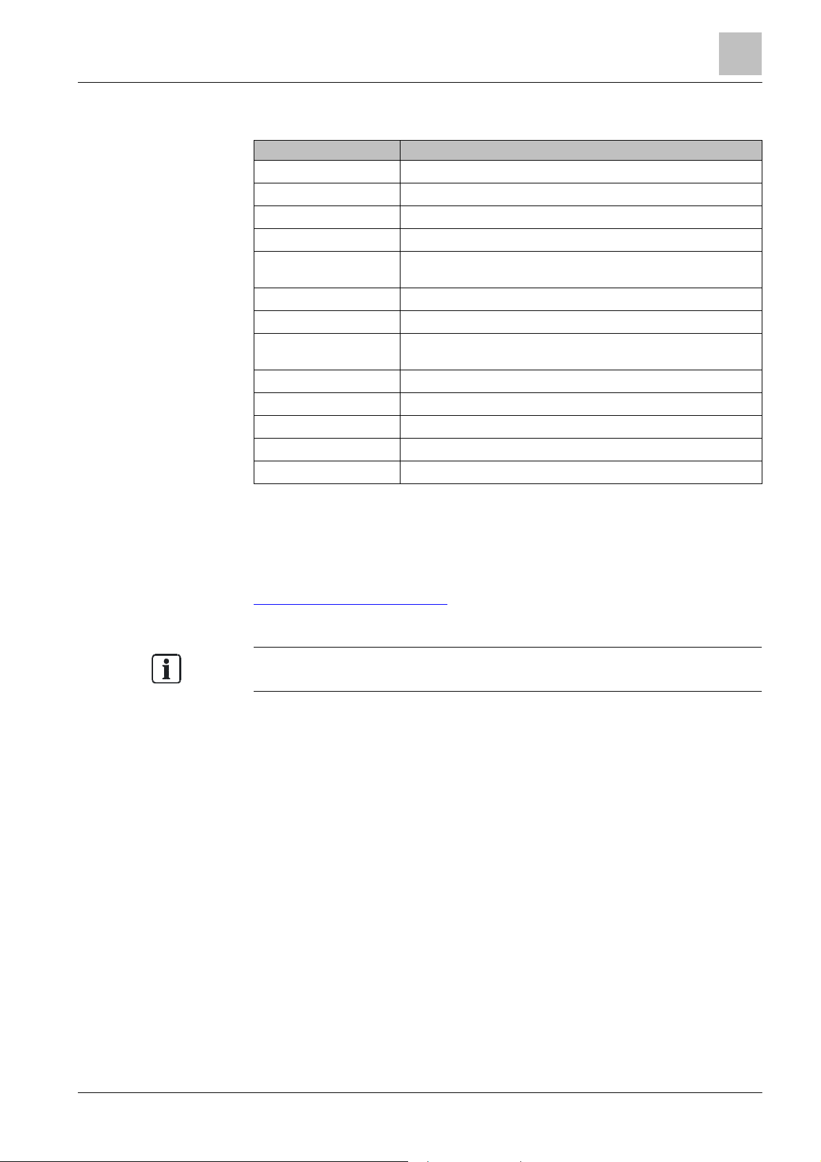
1.3 Technical terms
Term Explanation
AI Alarm indic a tor
dB Decibel: logarithmic relationship between two levels.
DOW1171 Radio smoke detector
DZW1171 Radio test set
EAI External alarm in dicator
EMC Electromagnetic compatibility
ERP Effective Radiated Power
FDnet Addr essed detec tor line
FDUL221 Line test er
FDUZ221 MCL-USB adapter. Protocol converter fro m USB to MC- Link.
Radio detec tor Devices which can communicate with the radio gateway usi ng radio.
Radio cell Radio ra nge, i.e. ran ge of a gateway
Gateway Network bridge which links two different systems or networks.
LED Light-e mitting diod e
MC link Maintenance and commiss ioning link
PC Personal computer
RadioSpy Test unit for observing, moni toring and configuring a radio detec tor cell.
SMF121 Manual call point
SMF6120 Radio base
SPU60xx Radio mod ul e
SRD band
USB Universal Serial Bus
Reserved frequency band with defined usage rules (Short Range Device
Band)
10 | 82
2015-11-06
About this document
Revision history
82
009865_m_en_
--
Fire Safety
1.4 Revision history
The first edition of a language version or a country variant may, for
example, be
The reference docum ent's version applies to all languages into which the reference
document is trans lated.
version 'd' inst ead of 'a' if the reference document is already this version.
The table below shows this document's revision history:
Version Edition da te Brief description
m 2015-11-06
l 2014-10-17
k 2014-09-03
j 2014-07-14
i 2012-05-15
h 2011-08
g 2010-12
f 2010- 07
e 2009-04
d 2007-08
c 2007-07
b 2007-04
a 2007-03
● New battery type 'EVE CR9V/P-S ' added to doc ument.
● Editorial changes
Chapter 'Updating the fir mware of radio gatew ay FDCW 21' revised.
External alarm indic ator remove d from 'Structure and function' chapter, sections 'Inter nal view' and
'Connections', 'Mounting / installation', and 'Commissioning'.
Data she et updated in 'Applicable documents' chapter
"External alarm indicators" section in 'Specifications' chapter removed
VdS approvals removed from 'Specifications' chapter for all 3 devices
'Download center' chapter added
Date format changed in line with the requirements of ISO 8601 (f ormat: yyyy-mm-dd), note added to
explai n t hat the SMF6120 may only be used as a replacement d evice in exis ting fire detectio n
installations installed prior to 2 011-04-01.
Editori al changes made, difference betw een FS20/FC20 revis ed; number of batteries for SMF612 0
and DOW1171 corrected; document numbers of mounting instr uctions for FDCW221 and
DOW1171/DBW1171 adapted; new standard, VdS approvals and CPD numbers for FDCW221 and
DOW1171 added to technical data
Editori al changes made
VdS approvals removed
Document title changed
Additional information about the radio smoke detector DOW1171 and the manual call point SMF121
added
Editori al changes made
New safety notes.
Radio gateway, with battery only and which can never be operate d in a 'stub to pology'.
Editori al changes made.
Diagnosis levels chapter: Displays as on the detector exchang er and tester.
Internal view chapter: MC link connection (general).
Hyperlinks in the PDF now function.
Review results incorporated:
- Additional 'SHIELD' spring clip
- Other LEDs in cover
- Only connect detector line later during co mmissioning
- IP40 pro tection category
- DOW117 1: Parameter set 1 is t he default
- DOW117 1: Status indicator rather tha n a larm indicator
- Switch off detector line when replacing the radio detector
Various supplements for DOW1171/SMF6120
Initial edition for VdS
1
Building Technologies
11 |
2015-11-06
About this document
Revision history
1
Building Technologies
009865_m_en_
--
Fire Safety
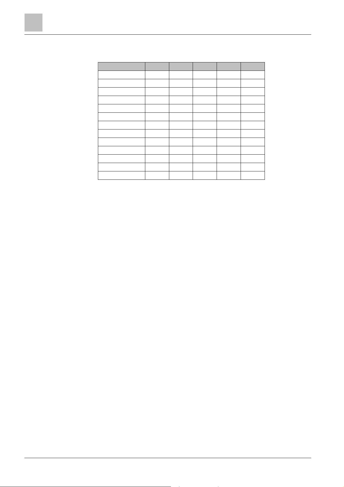
The table below shows the published language versions with the corresponding
modification index:
Modification in dex en_-- d e_-- fr_-- it_-- es_--
m X X X X X
l X X X X X
k – X – – –
j – X – – –
i X X X X X
h X X X X X
g – X – – –
f X X X X X
e – X – – –
d X X – – –
c X X – – –
b X X X X X
a X X X X X
X = published
– = no publication with this modification index
12 | 82
2015-11-06
Safety
Safety instructions
82
009865_m_en_
--
Fire Safety
2 Safety
2.1 Safety instructions
The safety notices mus t be observed in order to protect people and property.
The safety notices in this document contain the following elements:
● Symbol for danger
● Signal word
● Nature and origin of the danger
● Consequences if the danger oc curs
● Measures or prohibit ions for danger avoidance
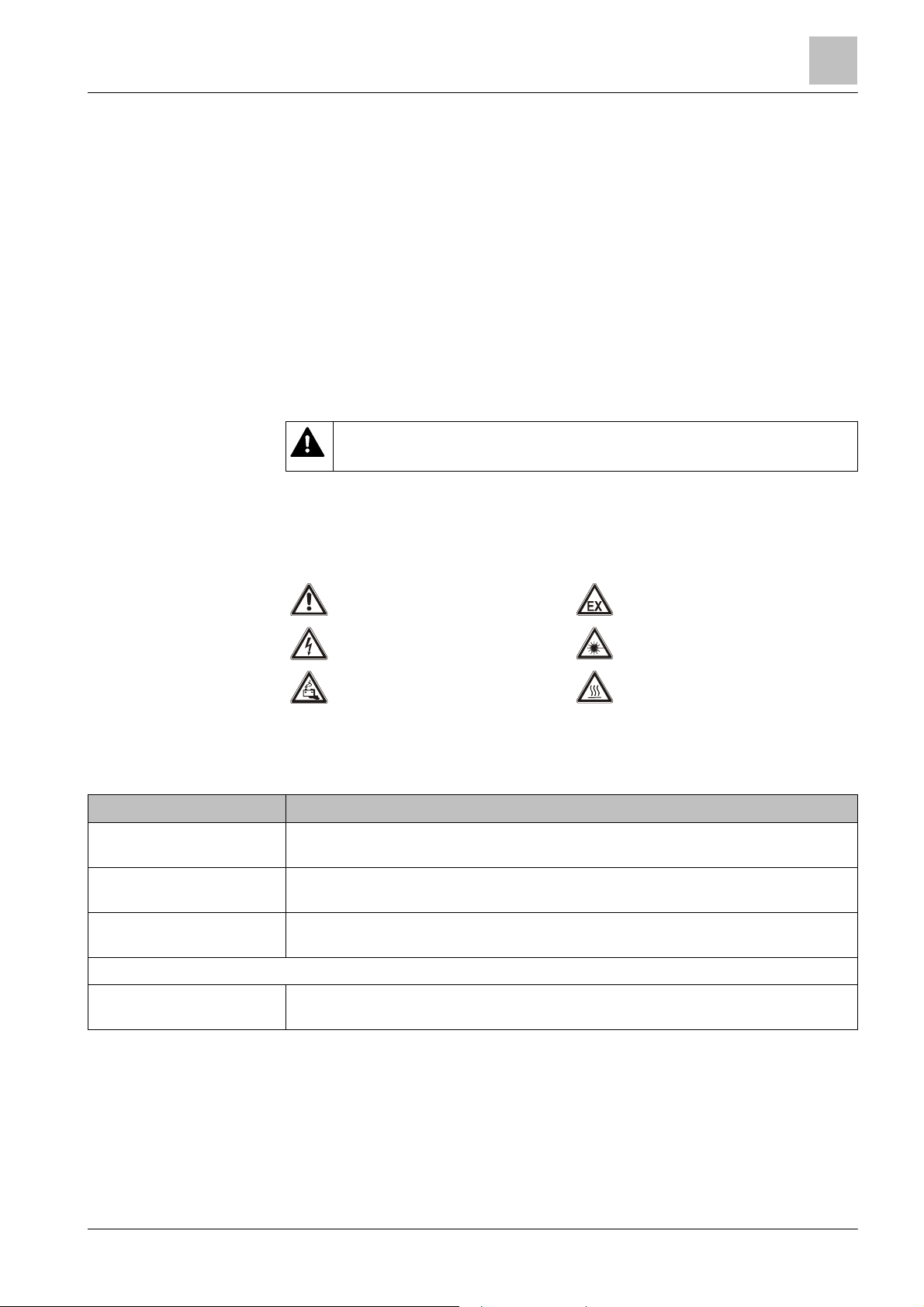
Symbol for danger
This is the symbol for danger. It warns of risks of injury.
Follow all measures ident ified by this symbol to avoid injury or deat h.
Additional dan ger symbols
These symbols indic ate general dangers, the type of danger or poss ible
consequences, measures and prohibitions, examples of which are shown in the
following table:
2
General danger Explosive atmosphere
Voltage/electric shock Laser light
Battery Heat
Signal word
The signal word classifies the danger as defined in the following table:
Signal word Dan ger level
DANGER
WARNING
CAUTION
NOTICE
DANGER identifies a dangerous situation, which will result direct ly in death or
serious injury if you do not avoid this situation.
WARNING identifies a dangerous situation, which may result in death or s erious
injury if you do not avoid this situation.
CAUTION identif ies a dangerous situation, which could result in slight to
moderately serious injury if you do not avoid this situation.
NOTICE
observance.
identifies possible damage to property that may result from non-
Building Technologies
13 |
2015-11-06
Safety
Safety instructions
2
Building Technologies
009865_m_en_
--
Fire Safety
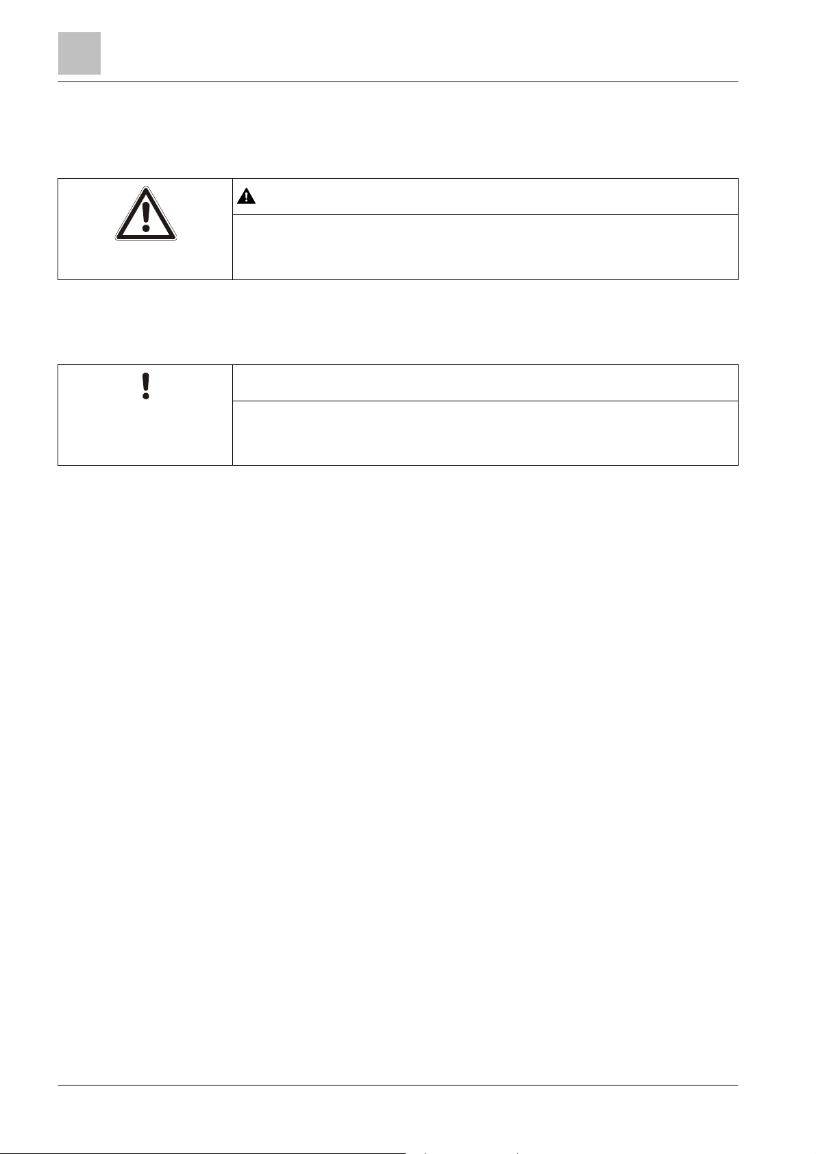
Nature and origin of the danger
●
Measures / prohibit ions for danger avoidance
Nature and origin of the danger
How risk of injury is presented
Information about the risk of injury is shown as follows:
WARNING
Consequences if the danger oc curs
How possible damage to property is presented
Information about possible damage to property is s hown as follows:
NOTICE
Consequences if the danger oc curs
● Measures / prohibit ions for danger avoidance
14 | 82
2015-11-06
Safety
Safety regulations for the method of operation
82
009865_m_en_
--
Fire Safety
2.2 Safety regulations for the method of operation
Electrical volt age
regulations.
National standards, regulations and legislation
Siemens products ar e developed and produced in compliance with the relevant
European and international safety standards . Should additional national or local
safety standards or legislation concerning the planning, mounting, installation,
operation or disposal of the product apply at the place of operation, then these
must also be taken into account together with the safety regulations in the product
documentation.
Electrical installations
WARNING
Electric shock
● Work on electrical installations may only be carried out by qualified
electricians or by instructed persons working under the guidance and
supervision of a qualified electrician, in accordanc e with the electrotechnic al
2
● Wherever possible disconnect products from the power supply when carrying
out commissioning, maintenance or repair work on them.
● Lock volt-free areas to prevent them being switched back on again by mistake.
● Label the connection terminals with external external voltage using a
'DANGER External voltage' sign.
● Route mains connect ions to products separately and fuse them with their own,
clearly marked fuse.
● Fit an easily accessible disconnecting device in acc ordance wit h IEC 60950-1
outside the installation.
● Produce earthing as stated in local safety regulations.
Mounting, installation, commissioning and maintenance
● If you require tools such as a ladder, these must be safe and must be intended
for the work in hand.
● When starting the fire control panel ensure that unstable conditions cannot
arise.
● Ensure that all point s listed in the 'Testing the product operability' section below
are observed.
● You may only set controls to normal function when the product operability has
been completely tested and the system has been handed over to the customer.
Building Technologies
15 |
2015-11-06

Saf
ety
Safety regulations for the method of operation
2
Building Technologies
009865_m_en_
--
Fire Safety
Testing the product operability
● Prevent the remote transmission from triggering erroneously.
● If testing building installations or activating devices from third- party companies,
you must collaborate with the people appointed.
● The activation of fire control installations for test purposes must not cause
injury to anyone or damage to the building installations. The following
instructions m ust be observed:
– Use the correct potential for activation; this is generally the potential of the
building installation.
– Only check controls up to the interface (relay with blocking option).
– Make sure that only the controls to be tested are activated.
● Inform people before testing the alarm devices and allow for pos sible panic
responses.
● Inform people about any noise or mist which may be produced.
● Before testing t he remote transmission, inform the corresponding alarm and
fault signal receiving stations.
Modifications to the system design and the products
Modifications to the system and to individual products m ay lead to faults,
malfunctioning and safety risks. Written confirmation must be obtained from
Siemens and the corresponding safety bodies for m odifications or additions.
Modules and spare parts
● Components and spare part s must comply with the technical specifications
defined by Siemens. Only use products specified or recommended by
Siemens.
● Only use fuses with the specified fuse characteristics.
● Wrong battery ty pes and impr oper battery changing lead to a ris k of explosion.
Only use the same battery type or an equivalent battery t ype recommended by
Siemens.
● Batteries must be disposed of in an environmentally friendly manner. Observe
national guidelines and regulations.
Disregard of the safety regulations
Before they ar e delivered, Siemens products are tested to ensure they function
correctly when used properly. Siemens disclaims all liability for damage or injuries
caused by the incorrec t application of the instructions or the disregard of danger
warnings contained in the documentation. This applies in particular to the following
damage:
● Personal injuries or damage to property caused by improper use and incorrect
application
● Personal injuries or damage to property caused by disregarding safety
instructions in the documentation or on the product
● Personal injury or damage to property caused by poor maintenance or lack of
maintenance
16 | 82
2015-11-06
Safety
Standards and directives complied with
82
009865_m_en_
--
Fire Safety
2.3 Standards and directives complied with
Limited or non
-
existent fire detection
detection installation.
Incorrect planning and/or configurat ion
detection installation.
A list of the standards and directives complied wit h is available from your Siemens
contact.
2.4 Release Notes
Limitations t o the configuration or use of devices in a fire detection inst allation with
a particular firmware version are possible.
WARNING
Personal injury and damage to property in the event of a fire.
● Read the 'Release Notes' before you plan and/or configure a fire detection
installation.
● Read the 'Release Notes' before you carry out a firmware update to a fire
2
NOTICE
Important st andards and specifications are not satisfied.
Fire detection installation is not accepted f or commissioning.
Additional expense result ing from necessary new planning and/ or configuration.
● Read the 'Release Notes' before you plan and/or configure a fire detection
installation.
● Read the 'Release Notes' before you carry out a firmware update to a fire
Building Technologies
17 |
2015-11-06
Structure and function
Release Notes
3
Building Technologies
009865_m_en_
--
Fire Safety
3 Structure and functio n
The radio gateway F DCW221 is used to monitor signals from radio detectors and
to transfer them via the FDnet to a fire control panel.
The radio gateway is operated on the FDnet. All devices which can be monitored
by the radio gateway are collectively known as a 'radio detectors'.
The FDCW221 radio gateway c an communicate with the following radio detectors:
● DOW1171 radio smoke detector
● Manual call point SMF121 with radio base SMF6120
The unit, comprising radio gateway and the radio detectors logged onto it, forms a
radio cell.
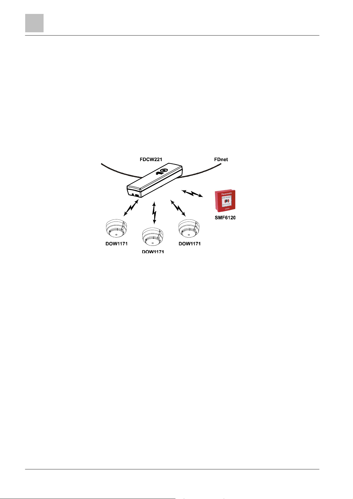
The following diagram shows how the radio gateway is integrated in the fire
detection via the FDnet.
Radio gateway on FDnet with radio detec tors
Features of the radio gateway FDCW221
● Compatible with the FDnet-compatible fire detection systems FS20, AlgoRex
and Sigmasys
● Simultaneous operat ion of wired fire detectors on FDnet and wireless radio
detectors on radio gateway
● High signaling securit y
– Automatic definition of optimum basic and deviating radio channels
– Automatic channel change in the event of radio problems
● Individual addressing for simple site identificat ion
● Up to 16 radio gateways can be operated with radio cell overlapping
● Up to 30 radio detectors can be activated per radio gateway
● Low current consumption, battery only needs replacing every 5 years
18 | 82
2015-11-06

Structure and function
Release Notes
3
82
009865_m_en_
--
Fire Safety
Features of the radio smoke detector DOW1171
● Consistent response to different fires
● Dynamic analysis of the sensor signal in the radio smoke detector itself
● Built-in diagnosis algorithms with automatic selftest
● High degree of immunit y towards false alarms and environmental influences
● High-quality, opto-electronic sensor system
● Automatic compensation for soiling
● Supply via two 9 V lithium bat teries
● Low current consumption, battery only needs replacing every 5 years
● Separate monitoring of each individual battery : Even when a battery fails,
detector operat ion is still guaranteed for up to 30 days
● Built-in alarm indicat or
● Mounting with detector base DBW1171 (accessories)
Features of the manual call point SMF121 and radio base SMF6120
● Radio module is integrated in the radio base SMF6120
● Radio base supply via two 3. 6 V lithium batteries
● Manual call point with indirect alarm activation: To trigger, drive in the washer
and press the knob
Applications
● For rooms of a high historical value, e.g. museums, churches, libraries.
● For rooms where cabling is not desired for esthetic reasons.
● For rooms where changes are alway s taking place, e.g. exhibition rooms.
Building Technologies
19 |
2015-11-06
Structure and function
Structure of the radio gateway FDCW221
3
Building Technologies
009865_m_en_
--
Fire Safety
2
354
3.1 Structure of the radio gateway FDCW221
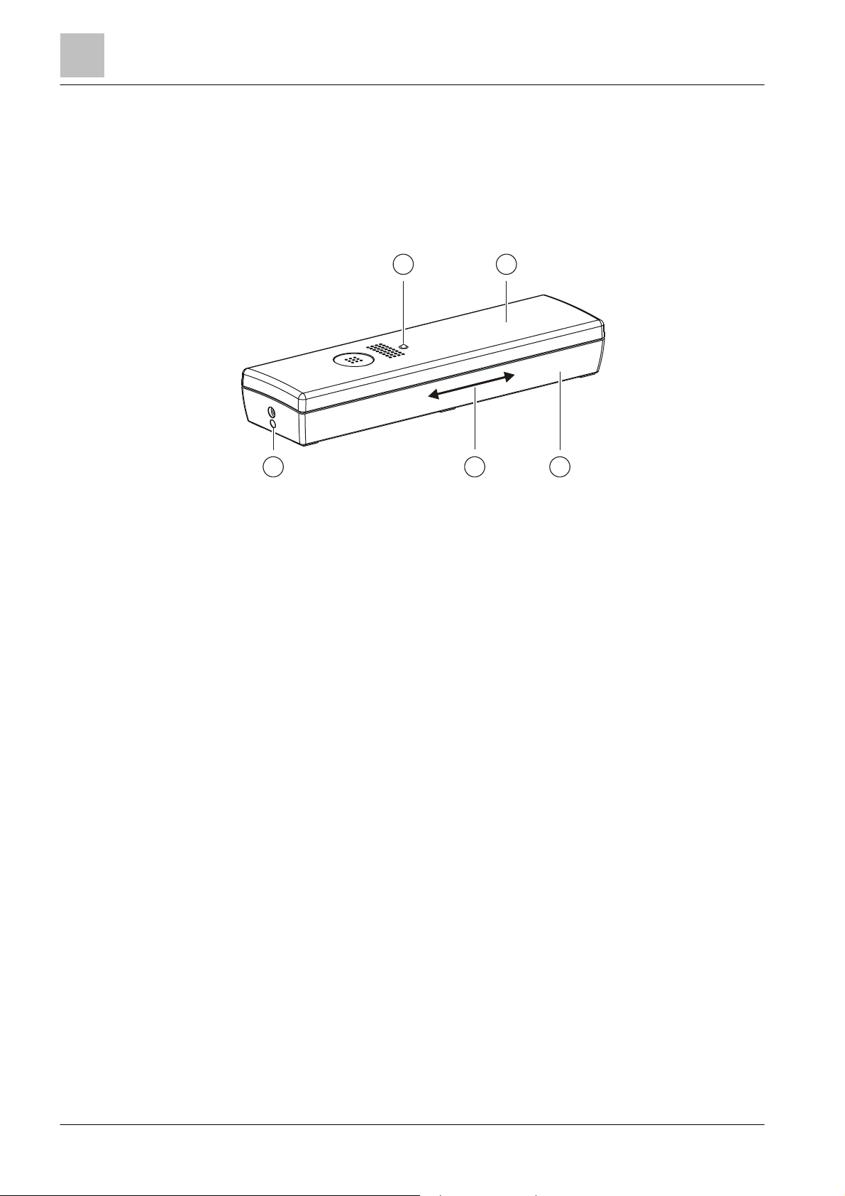
3.1.1 Overview
1
Overall view of radio gateway
1 LED red/green 4 Magnet movement for Reed
contact
2 Housing cover 5 Unlocking for housing cover
3 Back box
20 | 82
2015-11-06
Structur
e and function
Structure of the radio gateway FDCW221
82
009865_m_en_
--
Fire Safety
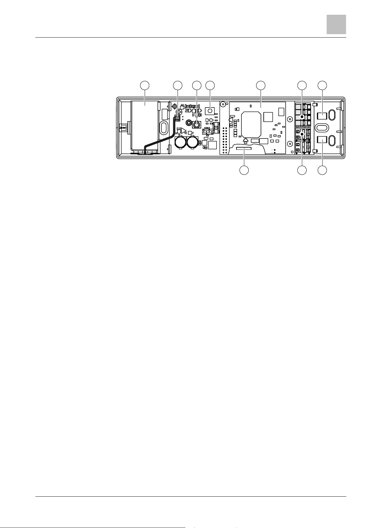
3.1.2 Internal view
5
6
778
9
3
1
Internal view of radio gatew ay
2 3 4
1 9 V battery with clip 6
2 Battery cable connection 7
3 MC link connection 8
'LINE' spring clips for the FDnet
detector line
Brackets for cable strain relief
using cable ties
'SHIELD' shield connection
terminal blocks for detector line
cables
4 Button for settings 9 Reed contact
5 Radio module SPU60xx
See also
2 Connections [➙ 22]
Building Technologies
21 |
2015-11-06
Structure and function
Structure of the radio gateway FDCW221
3
Building Technologies
009865_m_en_
--
Fire Safety
2
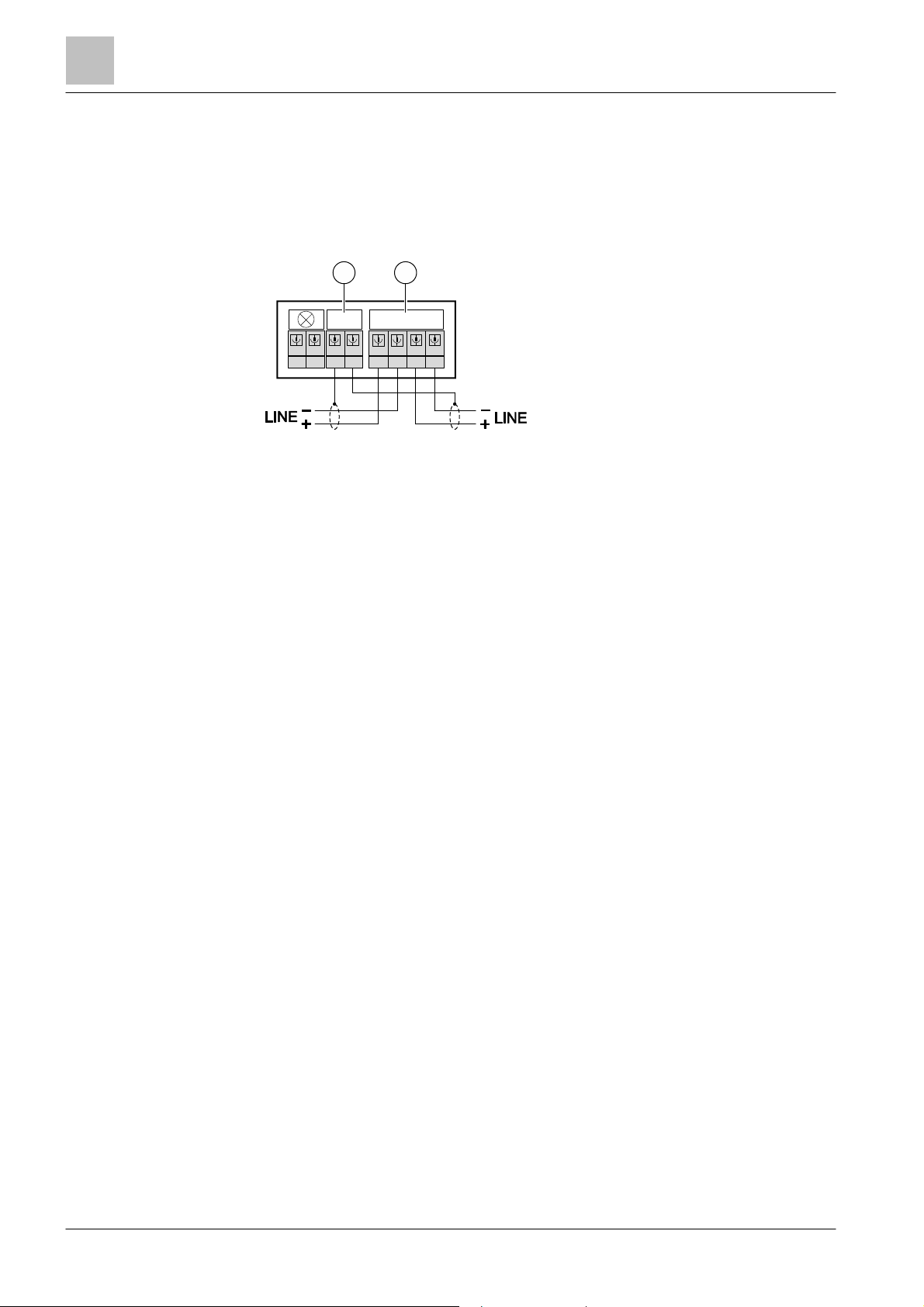
3.1.3 Connections
The radio gateway FDCW221 has connections for:
● The FDnet detector line
● The shieldings of the detector line cables
The two 'SHIELD' connection terminals are internally linked to one another.
1
SHIELD
_
+
Connections on FDCW221 radio gateway
1
Shield connection terminal blocks
for detector lines
LINE
__
++
2
Spring clips for the FDnet detector
line
MC link
The MC link connection in the radio gateway is mainly used to connect the detector
exchanger and tester FDUD292 and the intelligent detector tester FDUD293 (as of
software V2.1). These devices allow informat ion to be read from the radio gateway
for commissioning, maintenance and troubleshooting.
You will find more information in documents 007227 and 009718.
The MC link is also used to update the radio gateway firmware. The MCL-USB
adapter FDUZ221 is used to lead the firmware from the PC to the radio gateway.
You will find a descript ion of firmware update in chapter 'Updating t he firmware of
radio gateway FDCW 221 [➙ 73]'.
For details, see document 009854.
22 | 82
3.1.4 Radio transmission
The radio module SPU60xx consists of a printed circuit board with two integrated
aerials.
The radio module is a module which allows for bidirectional data trans mission in
the 868...870 MHz frequency range.
The radio module has a complete send and receive unit and a microcontroller
control unit for all radio transmission funct ions.
Radio transmission takes place in the SRD band (Short Range Devic e), a reserved
frequency band with defined usage rules. The SRD band is free from amateur
users. The SRD band provides 80 channels with a channel width of 25 kHz.
Characteristics of the SRD band:
● Defined low maximum transmitting powers and duty cycle (ratio between
send/idle time)
● Sub-bands for various uses and applications
● High availability
2015-11-06

Structure and function
Structure of the radio gateway FDCW221
82
009865_m_en_
--
Fire Safety
Characteristics of the radio module:
Batteries are not included in the scope of delivery. Batteries are always needed to
● 4 alternative channels ar e assigned to each of the 16 basic channels
(5 x 16 = 80 different channels)
– If there is a problem with the basic channel, this is detected right away. If
this happens, t he frequency automatically changes channel up to four
times.
● Communication faults between the gateway and the detectors are detected and
displayed within 300 s. Alarms are transferr ed immediately.
● If a detector cannot directly reach the gateway and the contact is interrupted, a
diversion mechanism is activated. The bidirec tional contact between the
detector and t he gateway then takes place via a neighboring detector of the
same radio cell.
If the problem persists for a long time, the diversion is displayed as a fault
within 300 s, like other communication faults.
3.1.5 Reed contact and button
The Reed contact is an extra operating element which can be used to perform
some of the functions of the button when the housing cover is closed.
Generally when commis sioning, the Reed contact can also be activated with a
magnet rather than the button. Activation of the Reed contact then equates to
briefly pressing the button.
The Reed contact is act ivated by slowly pulling (approx. one second) along the
length of the Reed cont act with a magnet.
3
See also
2 Internal view [➙ 21]
2 Status dis play on the radio gateway FDCW221 [➙ 39]
2 Overview [➙ 20]
3.1.6 Scope of delivery
The radio gateway is supplied with the following accessories :
● 1x battery connect ion cable (with 9 V battery clip and PCB plug)
● 2x cable ties (3.7 x 208 mm) for cable strain relief
commission and operate the radio gateway.
See also
2 Details for or dering [➙ 29]
2 9 V lithium manganese dioxide battery [➙ 30]
Building Technologies
23 |
2015-11-06
Structure and function
Structure of the radio smoke detector DOW1171
3
Building Technologies
009865_m_en_
--
Fire Safety
1
2
3
4
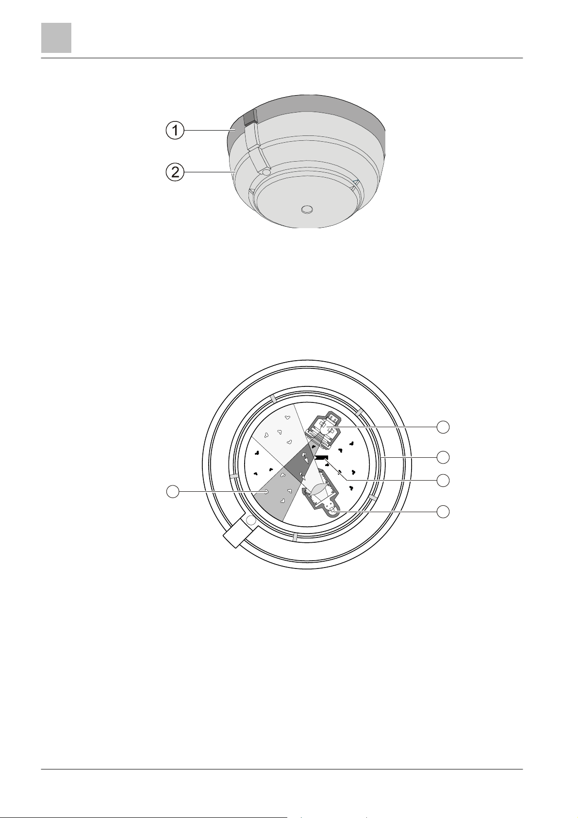
3.2 Structure of the radio smoke detector DOW1171
Radio smoke detector DOW1171 with base DBW1171
1 DBW1171 base 2 DOW1171 radio smoke detector
The radio smoke det ector DOW1171 works in line with the scattered light principle.
An infrared LED sends short, intense light pulses t o the scattering volume. The
orifices shield the light receiver from direct rays of light and reflexes. Penetrating
smoke particles scatter the light on the light receiver. The signal of the light
receiver is evaluated by the electronics.
Algorithms evaluate the smoke density and the probabilit ies of alarms are
forwarded by the mic roprocessor.
24 | 82
5
Cross-section through a radio smoke detector DOW1171
1 Light source (infrared LED) 4 Light receivers
2 Labyrinth 5 Smoke particle
3 Orifice
2015-11-06
Structure and function
Structure of the radio smoke detector DOW1171
82
009865_m_en_
--
Fire Safety
2
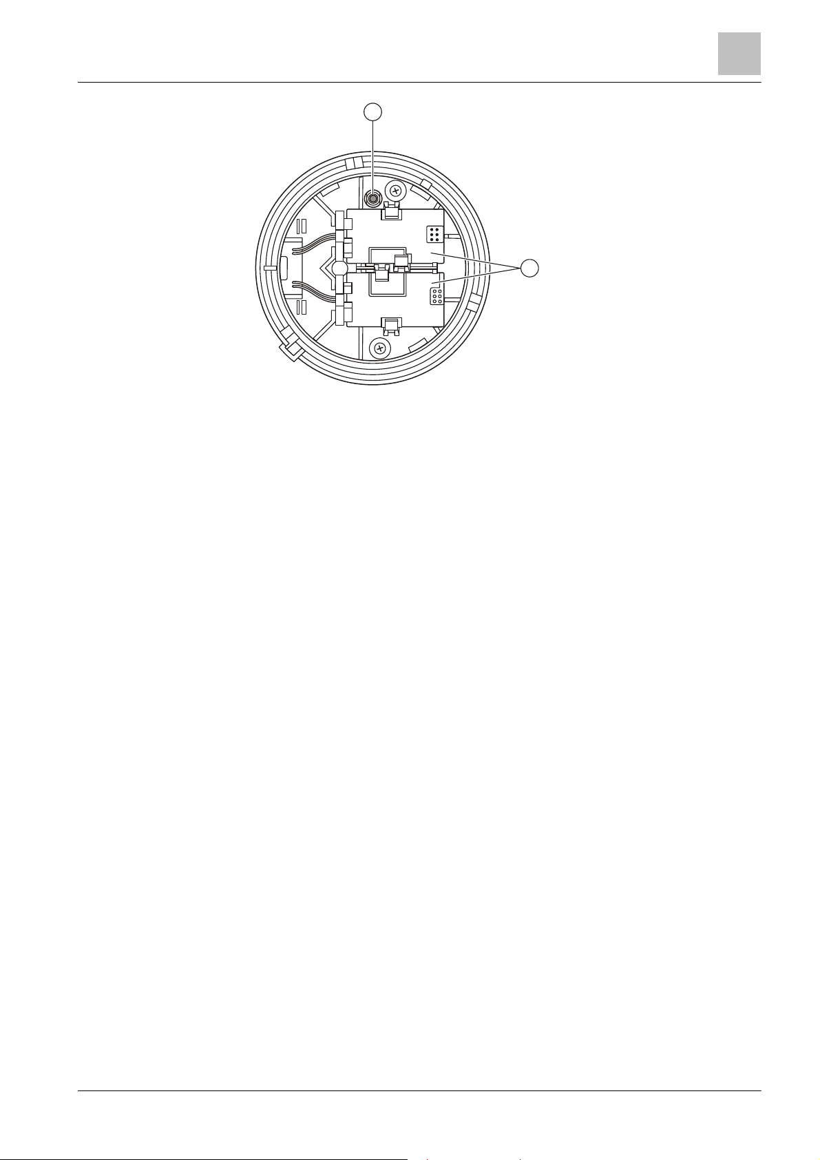
1
Battery compartment and log-on bu tton on the DOW117 1
3
1
Battery compartment for two 9 V
lithium manganese dioxide
batteries
See also
2 DBW1171 base [➙ 32]
2 Structure of the radio smoke detector DOW1171 [➙ 24]
2 'New' log-on button
Building Technologies
25 |
2015-11-06
 Loading...