

Siemens SM 338, POS INPUT Reference Manual

Copyright 2005 by Siemens AG
A5E00409892-01
Product Information on the Reference Manual
Programmable Logic Controllers S7-300 Module Data Release 3
1 Position Decoder Module SM 338; POS-INPUT;
(6ES7338-4BC01-0AB0)
Order number
6ES7338-4BC01-0AB0
Characteristics
The position decoder module SM 338; POS-INPUT is distinguished by the
following features:
• 3 inputs for the connection of maximum three absolute value encoders (SSI)
and 2 digital inputs to freeze the encoder values
• Direct reaction possible to encoder values in moving systems
• Processing of acquired encoder values of the SM 338 in user program
• Supports clocked operation
• Type of encoder value acquisition (see chapter 1.1.2.1) can be selected:
– Free running
– Clocked
• 24 VDC rated input voltage
• Non-isolated against the CPU
• Fast mode selectable; with faster encoder recording and compressed
checkback interface
Fast mode is available as of SM 338; POS-INPUT firmware version V2.0.0 and
as of STEP 7 V5.3+SP2 selectable.

2
Product Information on the Reference Manual Programmable Logic Controllers S7-300 Module Data Release 3
A5E00409892-01
Supported encoder types
The following encoder types are supported by the SM 338; POS-INPUT:
• Absolute value encoder (SSI) with 13-bit message length
• Absolute value encoder (SSI) with 21-bit message length
• Absolute value encoder (SSI) with 25-bit message length
Supported data formats
The SM 338; POS-INPUT supports the gray code and binary code data formats.
Firmware update
1)
You can use STEP 7 HW Config firmware update to load POS-INPUT in the
operating system memory of the SM 338 in order to extend the functionality and
trouble-shooting.
Note
The old firmware is deleted with the start of the firmware update. If the firmware
update is interrupted or canceled for any reason, the SM 338; POS-INPUT is no
longer functional. Restart the firmware update and wait until it has been
successfully completed.
1)
The function is only possible in distributed configuration if the header module (slave interface) supports the
necessary system services

3
Product Information on the Reference Manual Programmable Logic Controllers S7-300 Module Data Release 3
A5E00409892-01
1.1 Synchronous Operation
Warning
The basics of synchronous operation are described in a separate manual.
Hardware requirements
For the synchronous operation of the SM 338, you require:
• CPU which supports clocked operation
• DP master which supports the equidistant bus cycle
• Slave interface (IM 153-x) which supports synchronous operation
Characteristics
Depending on the system parameterization, the SM 338 works in either
non-synchronous or synchronous mode.
In synchronous operation, the data exchange between DP master and SM 338 is
synchronous to the PROFIBUS DP cycle.
In synchronous operation all 16 bytes of the checkback interface are consistent.
If synchronicity is lost due to faults or failure or delay of Global Control (GC), the
SM 338 goes back into synchronous operation in the next cycle without error
response.
If synchronicity is lost, the checkback interface is not updated.
4
Product Information on the Reference Manual Programmable Logic Controllers S7-300 Module Data Release 3
A5E00409892-01
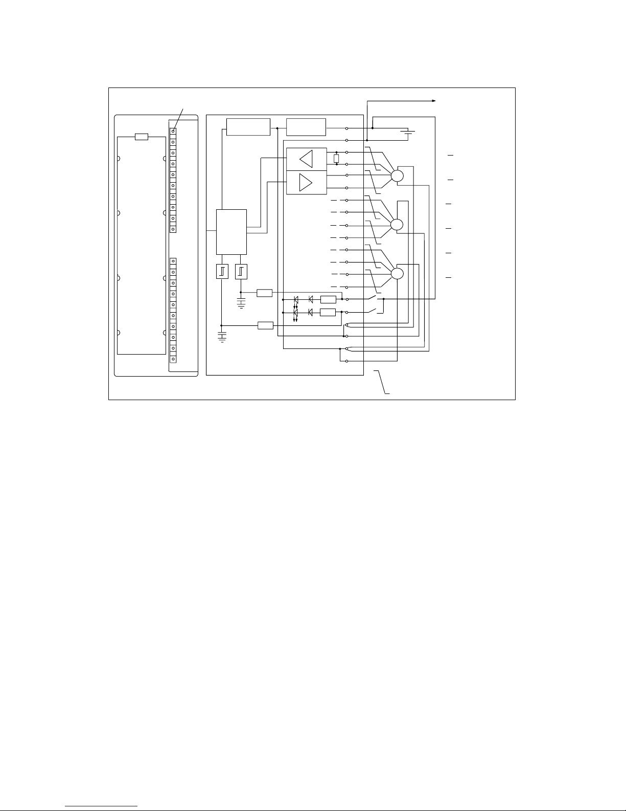
1.1.1 Terminal Connection Diagram and Block Diagram
Fault indicator – red
1
2
3
4
5
6
7
8
9
10
11
12
13
14
15
16
17
18
19
20
L+
24V
OD (Data)
OD (Data)
OC (Clock)
OC (Clock)
1D (Data)
1D (Data)
1C (Clock)
1C (Clock)
2D (Data)
2D (Data)
2C (Clock)
2C (Clock)
DI 0 (DigitalDI 1 input)
DC24V (encoder)
DC24V (encoder)
M (encoder)
M (encoder)
SSI
SSI
SSI
Short-circuit
protection
Voltage monitoring
SF
S7-300 Backplane bus
Logic
M
RS 422
Twisted pair cables
DI 0
DI 1
Connection to the
ground of the CPU
Figure 1-1 Module View and Block Diagram of the SM 338; POS-INPUT
Wiring rules
Please observe the following important rules of the wiring of the module:
• The ground of the encoder supply is connected non-isolated to the ground of
the CPU. Thus, connect pin 2 of the SM 338 (M) with low impedance with the
ground of the CPU.
• The encoder lines (pins 3 to 14) must be twisted pairs and shielded. Apply the
shield to both sides.
For the shield connection to the SM 338, use the shield connection element
(order number 6ES7390-5AA00-0AA0).
• If the output current (900 mA) of the encoder supply is exceeded, then you
must connect an external power supply.

5
Product Information on the Reference Manual Programmable Logic Controllers S7-300 Module Data Release 3
A5E00409892-01
1.1.2 Functions of the SM 338; POS INPUT
1.1.2.1 Encoder value acquisition
The absolute value encoder transfers its encoder values in messages to the
SM 338. The transfer of the message is initiated by the SM 338.
• In non-synchronous operation, the encoder values are acquired while it is free
running.
• In synchronous operation the encoder values are acquired synchronized to the
PROFIBUS DP cycle at each Ti.
Free running encoder value acquisition
The SM 338 always initiates the transfer of a message after the end of the
parameterized monoflop time.
Asynchronous to these free running messages, the SM 338 processes the
acquired encoder values during the cycle of its updating rate (see Technical Data).
Thus, in the case of free running encoder value acquisition, encoder values of
different ages result. The difference between the maximum and minimum age is
the jitter (see Technical Data).
Synchronous encoder values acquisition
Synchronous encoder values acquisition is automatically set if, in the DP master
system, the equidistant bus cycle is activated and the DP Slave is synchronized to
the DP cycle.
The SM 338 initiates the transfer of a message in each PROFIBUS DP cycle
at the time Ti.
Synchronous to the PROFIBUS DP cycle, the SM 338 processes the transferred
encoder values.

6
Product Information on the Reference Manual Programmable Logic Controllers S7-300 Module Data Release 3
A5E00409892-01
1.1.2.2 Gray/Dual Converter
In the Gray setting, the encoder values provided by the absolute value encoder in
gray code is converted into Dual code. In the Dual setting, encoder values
provided by the absolute value encoder remain unchanged.
Warning
If you have selected the Gray setting, the SM 338 always converts the entire
encoder value (13, 21, 25 bits). As a result, preceding special bits affect the
encoder values and following bits could be falsified under certain circumstances.
1.1.2.3 Transferred Encoder Value and Normalization
The transferred encoder value contains the encoder position of the absolute value
encoder. Depending on the encoder used, additional bits which are located before
and after the encoder position are also transferred in addition to the encoder
position.
So that the SM 338 can detect the encoder position, make the following settings:
• Normalization, places (0..12), or
• Normalization, units / revolution
Normalization, places
The normalization determines the position of the encoder values in the checkback
interface.
• If “Places” = 1, 2....12, this indicates that the following non relevant bits in the
encoder values are removed and the encoder value is right justified in the
address range (see following example).
• If “Places” = 0, this indicates that the following bits are retained and available
for evaluation.
This can be useful if you use an absolute value encoder which transfers
information in the following bits (see manufacturer information) and you want to
evaluate these (see also chapter 1.1.2.2).
Parameter units / revolution
A maximum of 13 bits are available for the units/revolution. According to the
“Places” data, the resulting number of units/revolution is automatically displayed.
 Loading...