

Siemens SLX-ASC-PFCU,SLX-ASC-PFCU-A,SLX Series,SLX-P-PTU-A,SLX-P-PTU Installation Instructions Manual
Installation Instructions
SLX Series
Document No. 997-1002
February 12, 2009
Power Fan Coil Unit Controllers
(SLX-ASC-PFCU and SLX-ASC-PFCU-A)
Power Terminal Unit Controllers
(SLX-P-PTU and SLX-P-PTU-A)
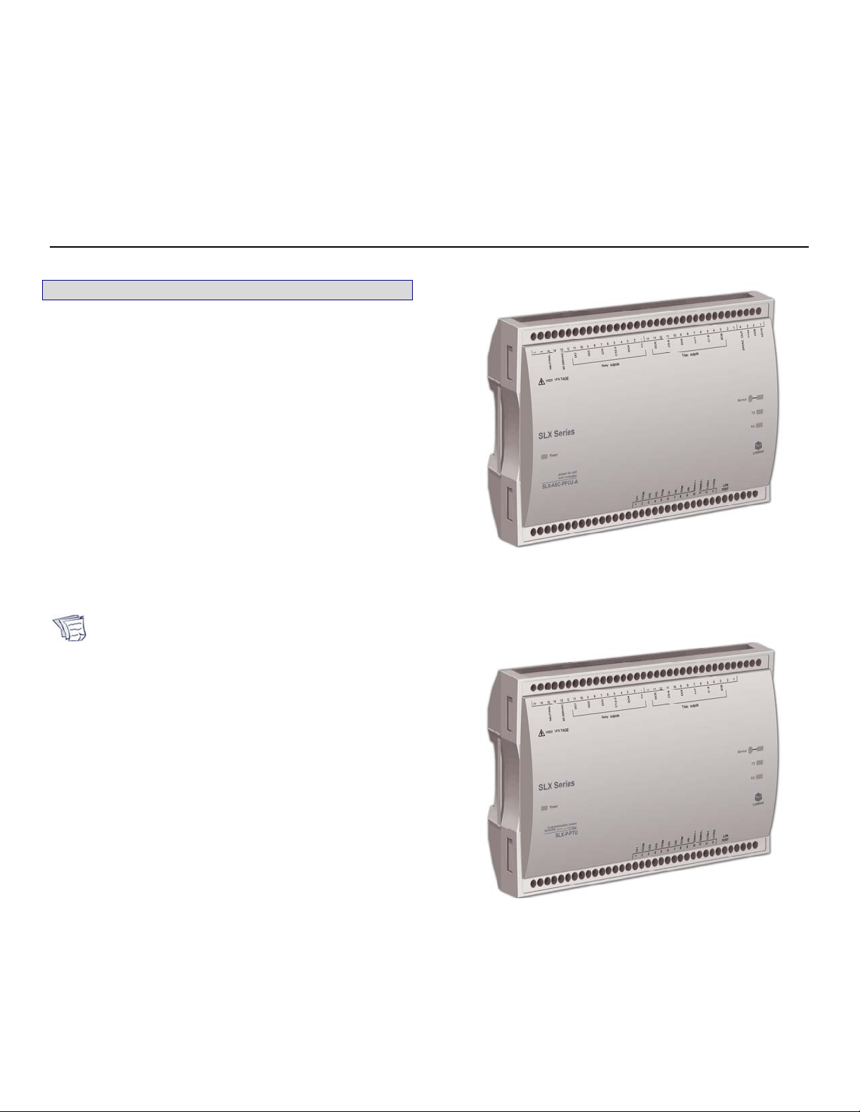
1. Product Description
This document describes the hardware installation procedures
for the SLX Series Power Fan Coil Unit (PFCU) controllers and
Power Terminal Unit Free Programmable (PTU) controllers.
The PFCU controllers are powered by 85-265VAC (24VAC
power generation is also available on SLX-ASC-PFCU-A
models). These controllers are designed to control fan coil unit
applications with up to three fan speeds and to meet the
requirements of both a two-pipe shared heating and cooling
coil, and four-pipe heating and cooling coil system.
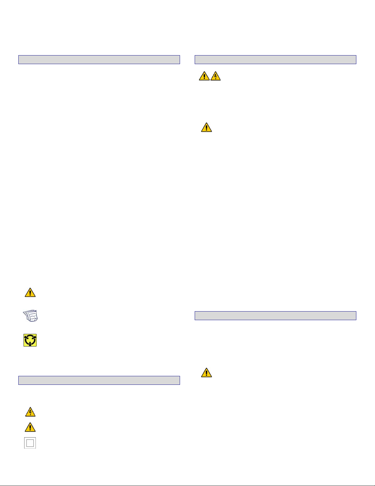
The PTU controllers are powered by 85-265VAC (24VAC
power generation is also available on SLX-P-PTU-A models).
These controllers are designed to control and monitor various
HVAC equipment such as fan coils, heat pumps, and ventilator
units, as well as chillers and boilers. Moreover, they are
suitable for any lighting control and power measurement
applications.
All of the controllers are based on the L
for peer-to-peer communication between controllers and are
LONMARK® certified.
Unless otherwise indicated, the term PFCU is used
in this document to represent both the SLX-ASCPFCU and SLX-ASC-PFCU-A models. Likewise,
PTU represents both the SLX-P-PTU and SLX-PPTU-A models.
All of these controllers are built on a similar
platform, but have different numbers of outputs.
Moreover, each individual model has different
amounts of digital and/or universal outputs. For
more information on the specific layout and
functionality of each controller, please refer to their
individual technical specification sheets.
ONWORKS
®
technology
SLX Series Page 1 of 8
Figure 1: SLX-ASC-PFCU-A.
Figure 2: SLX-P-PTU.
Document No. 997-1002
Installation Instructions
February 12, 2009
2. General Installation Requirements
4. General Wiring Recommendations
For proper installation and subsequent operation of each
controller, pay special attention to the following
recommendations:
- It is recommended that the controller(s) be kept at room
temperature for at least 24 hours before installation to
allow any condensation that may have accumulated, due
to low temperature during shipping or storage, to
evaporate.
- Upon unpacking the product, inspect the contents of the
carton for shipping damages. Do not install damaged
controllers.
- Allow for proper clearance of controller enclosure, wiring
terminals and service pin for easy access, hardware
configuration and maintenance. Remember to record the
®
Neuron
and barcode format) for later commissioning.
ID located on both sides of the controller (in text
- The controller is designed to operate under the following
environmental conditions:
Ambient temperature from 32°F to 122°F (0°C to 50°C)
Relative humidity from 0% to 90%, non-condensing.
- Ensure proper ventilation for the controller and avoid
areas where corroding, deteriorating or explosive vapors,
fumes or gases may be present. The controller must be
oriented with the ventilation slots and power supply/output
terminal block connector towards the top, for safety and to
permit proper heat dissipation.
- The plastic enclosure has a back plate that is separable
from the front plate, allowing the back plate (with the
connectors) to be shipped directly to the installation site
while all the engineering is done in the office.
- If the controller is used and/or installed in a manner not
specified, the functionality and the protection provided by
the controller may be impaired.
Any type of modification to any SLX Series product
will void the product’s warranty.
Take special care to keep the front and back plate
aligned when separating and joining them.
Take reasonable precautions to prevent
electrostatic discharges to the controller when
installing, servicing or operating the controller.
Discharge accumulated static electricity by
touching your hand to a securely grounded object
before working with this controller.
- All wiring must comply with electrical wiring diagrams as
well as national and local electrical codes.
- To connect the wiring to the controller, use the terminal
connectors. It is recommended to remove the front plate
from the back plate to facilitate the wiring process;
however, it is possible to do all wiring with the front and
back plates together. Use a small flat screwdriver to
tighten the terminal connector screws after the wires are
inserted.
- Power type cables (i.e. for power, 2- and 3-wire voltage
and current inputs and outputs, as well as relay and triac
outputs) should be kept apart from other types of wiring for
safety and to avoid any ambient noise transmission to
other wires.
- The board connectors accept wires or flat cables ranging
from 22 to 14AWG (0.644 to 1.630mm diameter) per pole.
However, power cables must remain between 18 and
14AWG (1.024 to 1.630mm diameter).
- Do not connect the universal inputs, analog outputs or
common terminals to earth or chassis ground (unless
stated otherwise).
- Keep all wires away from high speed data transmission
cables (ie. Ethernet, etc.).
- Keep input and output wiring in conduits or trays, or close
to the building frame if possible.
5. Mounting Instructions
Each controller can be mounted on a DIN rail to speed up the
installation process. The controllers are also equipped with two
mounting holes of 0.25” (6.35mm) by 0.165” (4.191mm). They
can be mounted in a panel or on a wall by using appropriate
screw types (use sheet metal, thread forming or self-tapping
screws accordingly).
3. Controller Markings (Symbols)
Certain markings (symbols) can be found on the back plate of
the controller and are defined as:
HIGH VOLTAGE Symbol: Direct contact will cause
electrical shock or burn.
Warning Symbol: Significant information required.
Refer to Hardware Installation Guide.
Double Insulation Symbol: These controllers are
built with double insulation.
Page 2 of 8 SLX Series
DIN Rail-Mounted Installation
1. Make sure that the DIN rail is properly mounted on the wall.
2. Simply clip controller onto the DIN rail.
Wall-Mounted Installation
1. Open the controller by separating the front and back plate
using the side clips.
2. From within the back plate use the mounting holes to mark
the location of any holes that need to be drilled.
Due to HIGH VOLTAGE, direct contact will
cause electrical shock or burn. Turn off power
before any kind of servicing.
It is recommended to use a 2-line main power
disconnect to be located near the controller (the
minimum power requirements: 300VAC, 20A).
Minimum cable temperature rating of all cables
must be 80°C.
Do not mount the controller on a flat surface where
the front plate would be facing up. It must be
mounted on a vertical surface such as a wall.
3. Remove the back plate and drill holes.
4. Finally, clean the perforated surface and fasten the
controller using the appropriate screw types.
For safety reasons it is recommended to install the
controller inside the fan coil unit box. Refer to
national and local electrical codes.
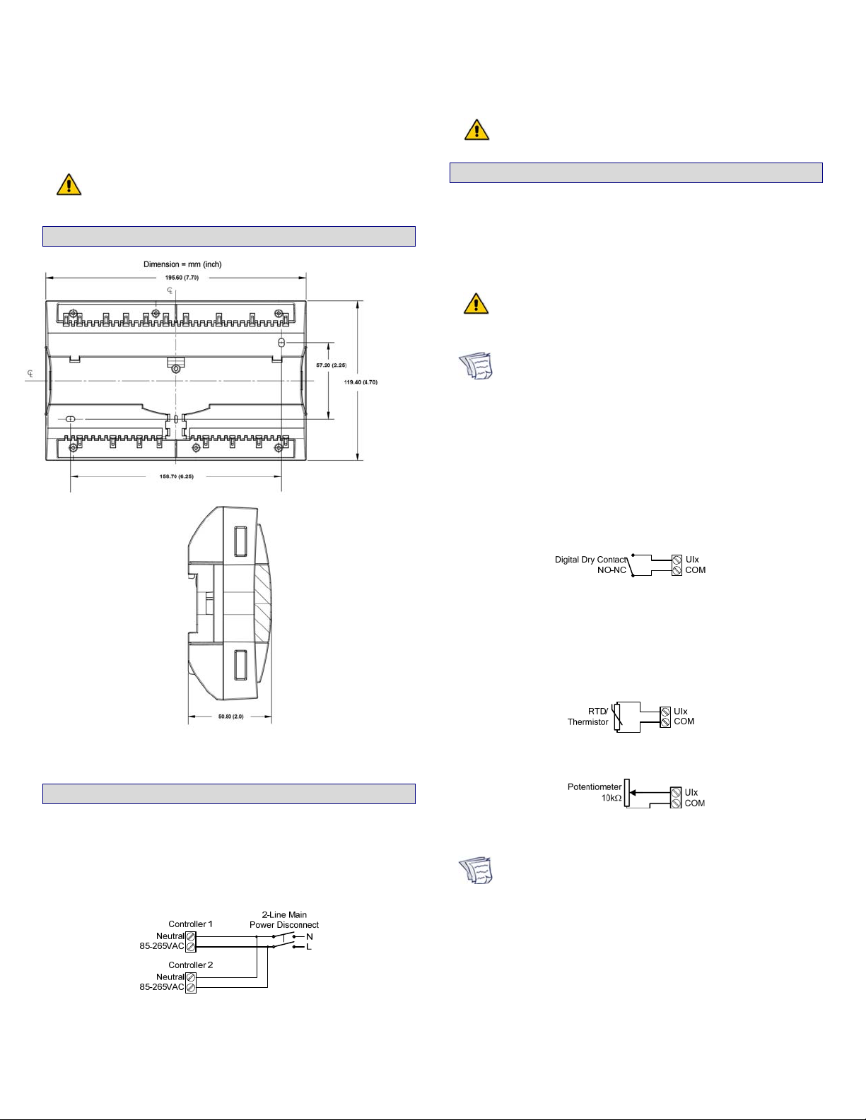
6. Controller Dimensions
Document No. 997-1002
Installation Instructions
February 12, 2009
The power wires must be at least 18AWG
(1.024mm).
8. Input Wiring
Each controller has physical connections for six (6) inputs that
are software configurable from within the controller's LNS
plug-in. Each input can be configured for digital, resistive,
current or voltage signals. Input types must be configured
properly in the software plug-in to ensure proper input
readings.
Before connecting any input equipment to the
controller, refer to the installation guide of the
equipment manufacturer.
®
For a wire length less than 75’ (23m), either a
•
shielded or unshielded 18AWG wire may be
used.
• For a wire length between 75’ and 200’ (23 to
61m), a shielded 18AWG wire is recommended.
• The wire should be shielded on the controller
side and the shield length should be kept as
short as possible.
Wiring Digital Inputs
This input configuration is used to monitor digital dry
contacts, as well as pulsed contacts (PTU controllers only).
Figure 3: PFCU and PTU Dimensions.
7. Power Wiring
Voltage: 85-265VAC; 50-60Hz
Max. Consumption: 33VA (SLX-ASC-PFCU-A and SLX-P-PTUA)
20VA (SLX-ASC-PFCU and SLX-P-PTU)
The controller is internally fuse-protected.
Figure 4: Power Wiring.
Figure 5: Digital Dry Contact (NO and NC).
Wiring Resistive Inputs
This input configuration is used to monitor 100Ω and 1000Ω
RTDs, 10kΩ type II and III thermistors, as well as 10kΩ and
100kΩ (PTU controllers only) potentiometers.
Figure 6: RTD /Thermistor Input.
Figure 7: 10kΩ Potentiometer Input.
When using a 100Ω input, the wire length should be
kept short so as to avoid a possible temperature
offset. For example, an 18AWG wire, 25’ (7.6m) in
length can create an offset of 2°F (1.1°C).
Wiring Current Inputs
Current inputs have a range of 4 to 20mA. Connect the
current input according to the following figure if a 2-wire, 420mA transducer is being used.
SLX Series Page 3 of 8
 Loading...