

Siemens SLT-1 Installation Instructions Manual
Installation Instructions
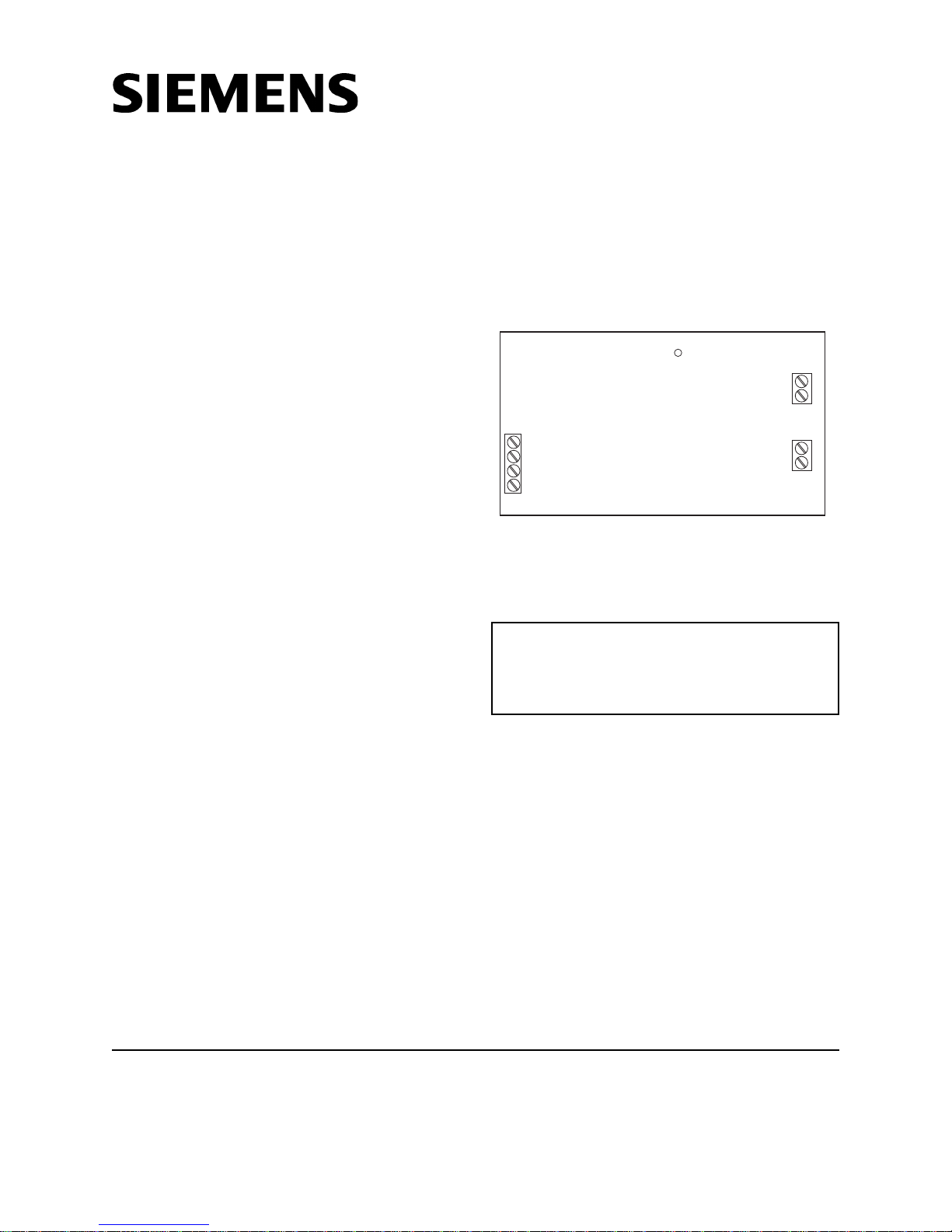
TB1
TB3
TB2
SLT-1
+24V
-V
DS1
Polling LED
Leased Line
Municipal Tie
DATA
EARTH
-
-
+
+
Model SLT-1
Leased Line/Municipal Tie Module
OPERATION
The Model SLT-1 module from Siemens Industry,
Inc., is used with the SXL-EX System to provide
connections for Leased Line and/or Municipal Tie.
Either or both connections can be used. Terminal
Block 1 (See Figure 1) provides the connection to
TB3 on the Main Board.
If the green LED (labeled DS1) on the module is
pulsing, it indicates that the module is active.
Effective with SLT-1 Rev. 1.1 and higher, and
SXL-EX Rev. 2.0 or higher, the SLT-1 will energize the municipal tie connection for one minute
after the last alarm received at the panel. Modules with firmware below this level will energize
the municipal tie connection until the panel is
reset.
With SLT-1 Rev. 1.1 and higher and SXL-EX Rev.
2.0 or higher, the municipal tie box can be reset
before the panel is reset. The SLT-1 continues to
energize the Leased Line connection until the
panel is reset for all firmware versions.
The SLT-1 causes a trouble on the display panel
when any of the following three conditions
occurs:
1. There is an open on the data line.
2. No SLT-1 module is connected to the System,
though there is an address for the module in
the System configuration.
3. An SLT-1 module is connected to the system,
but there is no address for it in the System
configuration.
Figure 1
SLT-1 Module
INSTALLATION
Remove all system power before
installation, first battery and then AC.
(To power up, connect the AC
first and then the battery.)
Installation in SXL-EX System
(Refer to Figure 2):
Install the SLT-1 in the upper right-hand portion of
the EN-SX enclosure according to the following
steps.
1. Insert the four 6-32 x 1/2 standoffs over the
four studs in the upper right-hand corner of
the SXL-EX enclosure as shown in Figure 2.
2. Place the upper four holes of the SLT-1 board
over the four standoffs in the upper right-hand
portion of the EN-SX enclosure. Using the
four 6-32 screws provided, fasten the SLT-1
board to the standoffs.
Siemens Industry, Inc.
Building Technologies Division
Florham Park, NJ
P/N 315-093285-10
Siemens Building Technologies, Ltd.
Fire Safety & Security Products
2 Kenview Boulevard
Brampton, Ontario
L6T 5E4 Canada

4X
Figure 2
Mounting the SLT-1 in an SXL-EX System
®
In an Existing SXL
System
(Refer to Figure 3):
To place the SLT-1 on the Main Board of an
existing system, first remove the existing Display
Board and its cover according to the following
steps.
1. Remove the Display Cover from the Display
Board as shown in Figure 3. Discard its top
two standoffs.
2. Unplug the ribbon cable from the Display
Board at jumper JP4 on the Main Board.
3. Remove the Display Board from the SXL
Main Board by unscrewing the four 6-32
screws and setting them to one side.
4. Remove and discard the two standoffs that
were supporting the two upper corners of
the Display Board.
5. Use the four 6-32 x 1-7/8 standoffs, the 6-32
screw, and the two 15/16 standoffs provided
as follows:
• Fasten one of the longer standoffs provided
to the back of the upper left-hand corner of
the SLT-1 with the screw provided.
• Remove the screw from the upper right-
hand corner of the Main board.
• Screw another long standoff to the upper
right-hand corner of the Main board.
• Screw the last two long standoffs provided
to the Main board as shown in Figure 3.
6. Place the SLT-1 module on the standoffs that
were installed in Step 5 above.
7. Fasten the two short standoffs remaining to
the bottom two corners of the SRC-8 board
(They are supports for the Display Board).
8. Once the SLT-1 is in place, re-install the
Display Board by reversing Steps 1-3 above.
4X
Figure 3
Mounting the SLT-1 in an Existing SXL® System
PROGRAMMING
Use SXL Program Level 9 to program the SLT-1
module. (Refer to the SLX-EX Manual, P/N 315-
095997.)
1. To enter the System:
a. Press the RESET and DRILL keys at the
same time.
b. Enter your password (Refer to Enter
Password under PROGRAM MODE in the
Manual.)
c. Press the SILENCE key to confirm the
information for the system.
d. An A should display in the 7-segment
display.
e. If an F appears, repeat the process until
an A appears.
2. To enter the Program Mode:
a. Press the ACK key once.
b. Note that a P displays in the 7-segment
display.
c. Be sure the PROGRAM/TEST LED is lit.
3. To select the desired Program Mode
level:
a. To select Program Level 9, press
the RESET button 9 times.
b. Press SILENCE.
2
 Loading...