

Siemens SIWAREX WT241 User Manual

Weighing systems
Electronic weighing system
SIWAREX WT241
Manual
05/2015
A5E36046748A
Introduction
1
Safety guidelines
2
Description
3
Application planning
4
Installation
5
Connecting
6
Commissioning
7
Scale parameters and
functions of the belt scale
8
Messages
9
Command lists
10
Communication
11
Technical specifications
12
Accessories
13
ESD guidelines
B
List of abbreviations
C

Siemens AG
Division Process Industries and Drives
Postfach 48 48
90026 NÜRNBERG
GERMANY
Order number: A5E33713528A
Ⓟ 05/2015 Subject to change
Copyright © Siemens AG 2015.
All rights reserved
DANGER
indicates that death or severe personal injury will result if proper precautions are not taken.
WARNING
indicates that death or severe personal injury may result if proper precautions are not taken.
CAUTION
indicates that minor personal injury can result if proper precautions are not taken.
NOTICE
indicates that property damage can result if proper precautions are not taken.
WARNING
Siemens products may only be used for the applications described in the catalog and in the relevant technical
documentation. If products and components from other manufacturers are used, these must be recommended
or approved by Siemens. Proper transport, storage, installation, assembly, commissioning, operation and
maintenance are required to ensure that the products operate safely and without any problems. The permissible
ambient conditions must be complied with. The information in the relevant documentation must be observed.
Legal information
Warning notice system
This manual contains notices you have to observe in order to ensure your personal safety, as well as to prevent
damage to property. The notices referring to your personal safety are highlighted in the manual by a safety alert
symbol, notices referring only to property damage have no safety alert symbol. These notices shown below are
graded according to the degree of danger.
If more than one degree of danger is present, the warning notice representing the highest degree of danger will
be used. A notice warning of injury to persons with a safety alert symbol may also include a warning relating to
property damage.
Qualified Personnel
The product/system described in this documentation may be operated only by personnel qualified for the specific
task in accordance with the relevant documentation, in particular its warning notices and safety instructions.
Qualified personnel are those who, based on their training and experience, are capable of identifying risks and
avoiding potential hazards when working with these products/systems.
Proper use of Siemens products
Note the following:
Trademarks
All names identified by ® are registered trademarks of Siemens AG. The remaining trademarks in this publication
may be trademarks whose use by third parties for their own purposes could violate the rights of the owner.
Disclaimer of Liability
We have reviewed the contents of this publication to ensure consistency with the hardware and software
described. Since variance cannot be precluded entirely, we cannot guarantee full consistency. However, the
information in this publication is reviewed regularly and any necessary corrections are included in subsequent
editions.

Table of content
1 Introduction ............................................................................................................................................. 9
1.1 Purpose of the manual .............................................................................................................. 9
1.2 Basic knowledge required ......................................................................................................... 9
1.3 Manual - range of validity .......................................................................................................... 9
1.4 Technical support .................................................................................................................... 10
2 Safety notes .......................................................................................................................................... 13
2.1 General safety instructions ..................................................................................................... 13
3 Description ............................................................................................................................................ 15
3.1 Product overview .................................................................................................................... 15
3.2 Area of application .................................................................................................................. 15
3.3 SIWAREX WT241 product overview ...................................................................................... 16
3.4 Customer benefits ................................................................................................................... 17
3.5 Scope of delivery .................................................................................................................... 17
4 Application planning .............................................................................................................................. 19
4.1 Functions ................................................................................................................................ 19
5 Installation ............................................................................................................................................ 20
5.1 Installation guideline ............................................................................................................... 20
5.2 EMC-compliant setup.............................................................................................................. 21
5.2.1 Introduction ............................................................................................................................. 21
5.2.2 Possible effects of interference ............................................................................................... 21
5.2.3 Coupling mechanisms............................................................................................................. 21
5.2.4 Five basic rules for securing EMC .......................................................................................... 21
6 Connecting ........................................................................................................................................... 23
6.1 Overview ................................................................................................................................. 23
6.2 Connecting to main voltage .................................................................................................... 26
6.3 Connecting the load cells ........................................................................................................ 28
6.3.1 Connection of an MLC / MBS / MUS / MCS / MSI / MMI belt scale to WP241 ...................... 30
6.3.2 Connection of any scales or load cells ................................................................................... 32
6.4 Shield connection .................................................................................................................... 35
6.5 Connection of digital outputs (4 x DQ) .................................................................................... 36
6.6 Connection of digital inputs (4 x DI) ........................................................................................ 37
6.7 Connection of the analog output (1 x AQ) .............................................................................. 38
6.8 Connection of RS485 serial interface ..................................................................................... 38
6.9 Connection of a speed sensor ................................................................................................ 39
6.9.1 RBSS / WS100 speed sensor on WT241 ............................................................................... 39
6.9.2 TASS speed sensor on WT241 .............................................................................................. 40
SIWAREX WT241
Manual, 05/2015, A5E36046748A 3

Introduction
1.1 Purpose of the manual
6.9.3 WS300 speed sensor on WT241 ........................................................................................... 41
7 Commissioning ..................................................................................................................................... 43
7.1 Introduction ............................................................................................................................ 43
7.2 Factory-set parameters .......................................................................................................... 43
7.3 Commissioning via Quick Start routine .................................................................................. 44
7.3.2 Commissioning without speed sensor ................................................................................... 47
7.3.3 Determination of a correction factor ....................................................................................... 57
8 Scale parameters and functions of the belt scale ................................................................................... 59
8.1 SIWAREX WT241 Operating View ........................................................................................ 59
8.1.1 Dynamic status in operating view .......................................................................................... 60
8.2 Menu tree ............................................................................................................................... 62
8.3 Menu 1.1 Basic parameters ................................................................................................... 63
8.4 Menu 1.2 Calibration .............................................................................................................. 65
8.5 Menu 1.3 Limits ...................................................................................................................... 65
8.6 Menu 1.4 Additional parameters ............................................................................................ 66
8.7 Menu 1.5 Communication & interfaces .................................................................................. 68
8.8 Menu 1.6 Recovery / reset ..................................................................................................... 72
8.9 Menu 2.1 Messages ............................................................................................................... 72
8.10 Menu 2.2 Scale status ........................................................................................................... 73
8.11 Menu 2.3 Flow trend .............................................................................................................. 76
8.12 Menu 2.4 Module information ................................................................................................ 76
8.13 Menu 2.5 Start & stop trace ................................................................................................... 77
8.14 Menu 3.0 Language, Date & Time ......................................................................................... 77
8.15 Menu 4.0 Totalizers ............................................................................................................... 77
8.16 Menu 5.0 User management ................................................................................................. 79
8.17 Screen saver .......................................................................................................................... 80
9 Messages ............................................................................................................................................. 81
9.1 Message types ....................................................................................................................... 81
9.2 Message paths ....................................................................................................................... 82
9.3 Message list ........................................................................................................................... 83
9.3.1 System status message list ................................................................................................... 83
9.3.2 Technology error message list ............................................................................................... 83
9.3.3 Data and operating errors message list ................................................................................. 84
10 Command lists ...................................................................................................................................... 87
10.1 Overview ................................................................................................................................ 87
10.2 Command lists ....................................................................................................................... 88
11 Communication ..................................................................................................................................... 93
SIWAREX WT241
4 Manual, 05/2015, A5E36046748A

Introduction
1.1 Purpose of the manual
11.1 Communication via Modbus ................................................................................................... 93
11.1.1 General information ................................................................................................................ 93
11.1.2 Principle of data transmission ................................................................................................. 93
11.1.3 Data record concept ................................................................................................................ 94
11.1.4 Command mailboxes .............................................................................................................. 95
11.1.5 Reading registers .................................................................................................................... 95
11.1.6 Writing registers ...................................................................................................................... 96
11.2 Parameters and functions ....................................................................................................... 97
11.3 DR 2 command code .............................................................................................................. 98
11.4 DR 3 Belt scale parameters .................................................................................................... 98
11.4.1 Scale name ........................................................................................................................... 101
11.4.2 Code for regulations.............................................................................................................. 101
11.4.3 Unit for belt load .................................................................................................................... 102
11.4.4 Unit for flow rate .................................................................................................................... 102
11.4.5 Resolution of weight and belt load ........................................................................................ 102
11.4.6 Resolution of flow rate .......................................................................................................... 103
11.4.7 Resolution of master totalizer ............................................................................................... 103
11.4.8 Design flow rate .................................................................................................................... 103
11.4.9 Weigh length ......................................................................................................................... 103
11.4.10 Belt length ............................................................................................................................. 104
11.4.11 Number of belt revolutions .................................................................................................... 104
11.4.12 Speed detection .................................................................................................................... 104
11.4.13 Design speed ........................................................................................................................ 104
11.4.14 Speed correction if belt loaded ............................................................................................. 104
11.4.15 Belt load factor for speed correction ..................................................................................... 105
11.4.16 Impulse constant speed sensor ............................................................................................ 105
11.4.17 Initial zero calibration digits ................................................................................................... 105
11.4.18 Calibration weight ................................................................................................................. 106
11.4.19 Calibration load ..................................................................................................................... 106
11.4.20 Calibration quantity ............................................................................................................... 106
11.4.21 Span calibration digits ........................................................................................................... 106
11.4.22 Simulation mode ................................................................................................................... 106
11.4.23 Warm-up timer ...................................................................................................................... 107
11.4.24 Interface for the legal trade display ....................................................................................... 107
11.4.25 Software version for HMI SecureDisplay with verification capability .................................... 107
11.4.26 Minimum display size in % of the HMI SecureDisplay with verification capability ................ 107
11.5 Calibration procedure............................................................................................................ 108
11.5.1 General information .............................................................................................................. 108
11.5.2 Calibration of the speed ........................................................................................................ 108
11.5.3 Specification of known speed parameters ............................................................................ 110
11.6 Calibration of weight measurement ...................................................................................... 111
11.6.1 Determination of zero point ................................................................................................... 111
11.6.2 Span calibration by weight .................................................................................................... 111
11.6.3 Automatic span calibration with load cell data ...................................................................... 112
11.6.4 Span calibration by test chain ............................................................................................... 113
11.6.5 Span calibration with known material flow ............................................................................ 113
11.7 DR 4 Temporary parameters ................................................................................................ 115
11.7.1 Stop watch ............................................................................................................................ 117
11.7.2 Result calculator ................................................................................................................... 117
SIWAREX WT241
Manual, 05/2015, A5E36046748A 5

Introduction
1.1 Purpose of the manual
11.8 DR 5 Correction factors for material flow rate ...................................................................... 118
11.8.1 Belt load factor 1 .................................................................................................................. 119
11.8.2 Belt load factor 2 .................................................................................................................. 119
11.8.3 Correction factors 1 and 2 .................................................................................................... 119
11.9 DR 6 Limits ........................................................................................................................... 120
11.9.1 Negative and positive zero offset in % ................................................................................. 122
11.9.2 Smallest totalized value ....................................................................................................... 122
11.9.3 Minimum flow rate ................................................................................................................ 122
11.9.4 Maximum flow rate ............................................................................................................... 122
11.9.5 Delay for flow rate limits ....................................................................................................... 122
11.9.6 Minimum belt speed ............................................................................................................. 122
11.9.7 Maximum belt speed ............................................................................................................ 122
11.9.8 Delay for belt speed limits .................................................................................................... 123
11.9.9 Minimum belt load ................................................................................................................ 123
11.9.10 Maximum belt load ............................................................................................................... 123
11.9.11 Delay for belt load limits ....................................................................................................... 123
11.9.12 Medium load for totalizing .................................................................................................... 123
11.9.13 Frequency low pass filter weight/belt load/belt speed ......................................................... 124
11.9.14 Order no low pass filter ........................................................................................................ 124
11.9.15 Depth average filter flow rate ............................................................................................... 124
11.10 DR 7 Process interfaces ...................................................................................................... 125
11.10.1 Assignment digital input DI 0, 1, 2, 3 ................................................................................... 128
11.10.2 Input filtering (hardware setting) .......................................................................................... 128
11.10.3 Assignment digital output DQ 0, 1, 2, 3 ............................................................................... 128
11.10.4 Response of digital outputs to faults or SIMATIC STOP ..................................................... 129
11.10.5 Substitute value for DQ 0, 1, 2, 3 following fault or SIMATIC STOP ................................... 129
11.10.6 Analog output range ............................................................................................................. 130
11.10.7 Analog output source ........................................................................................................... 130
11.10.8 Response of analog output to faults or SIMATIC STOP...................................................... 130
11.10.9 Start value for the analog output .......................................................................................... 131
11.10.10 End value for the analog output ........................................................................................... 131
11.10.11 Output value following fault or SIMATIC STOP ................................................................... 131
11.10.12 Trace recording cycle ........................................................................................................... 131
11.10.13 Trace storage method .......................................................................................................... 131
11.10.14 Load per pulse ..................................................................................................................... 132
11.11 DR 8 date and time .............................................................................................................. 133
11.12 DR 9 module information ..................................................................................................... 134
11.13 DR 10 load cell parameters ................................................................................................. 135
11.13.1 Number of load cells ............................................................................................................ 135
11.13.2 50/60 Hz toggling ................................................................................................................. 136
11.13.3 Load cell characteristic value ............................................................................................... 136
11.13.4 Rated load of a load cell ...................................................................................................... 136
11.14 DR 12 Ethernet parameters ................................................................................................. 137
11.14.1 Device MAC address ........................................................................................................... 138
11.14.2 Port MAC address ................................................................................................................ 138
11.14.3 IP address ............................................................................................................................ 138
11.14.4 Subnet mask ........................................................................................................................ 138
11.14.5 Gateway ............................................................................................................................... 139
11.14.6 Device name ........................................................................................................................ 139
SIWAREX WT241
6 Manual, 05/2015, A5E36046748A

Introduction
1.1 Purpose of the manual
11.15 DR 13 RS485 parameters .................................................................................................... 140
11.15.1 RS485 protocol ..................................................................................................................... 141
11.15.2 RS485 baud rate ................................................................................................................... 142
11.15.3 RS485 character parity ......................................................................................................... 142
11.15.4 RS485 number of data bits ................................................................................................... 142
11.15.5 RS485 number of stop bits ................................................................................................... 142
11.15.6 RS485 Modbus address ....................................................................................................... 142
11.15.7 Modbus RTU response delay ............................................................................................... 143
11.16 DR 15 belt angle ................................................................................................................... 144
11.16.1 Current belt angle ................................................................................................................. 144
11.17 DR 16 Simulation (belt speed and belt load) ........................................................................ 145
11.17.1 Value for belt load simulation ................................................................................................ 145
11.17.2 Value for belt speed simulation ............................................................................................. 145
11.18 DR 17 Control analog output ................................................................................................ 146
11.18.1 Analog output specification ................................................................................................... 146
11.19 DR 18 Control digital output .................................................................................................. 147
11.19.1 Definition for digital output DQ.0, 1, 2, 3 ............................................................................... 148
11.20 DR 19 External speed ........................................................................................................... 149
11.21 DR 20 Message configuration .............................................................................................. 150
11.22 DR 21 Calculator ................................................................................................................... 152
11.23 DR 30 Process state ............................................................................................................. 153
11.23.1 Current weight ....................................................................................................................... 155
11.23.2 Current belt load ................................................................................................................... 156
11.23.3 Current belt load in % ........................................................................................................... 156
11.23.4 Current flow rate ................................................................................................................... 156
11.23.5 Current flow rate in % ........................................................................................................... 156
11.23.6 Current speed ....................................................................................................................... 156
11.23.7 Current speed in % ............................................................................................................... 156
11.23.8 Current master totalizer (S1) ................................................................................................ 156
11.23.9 Current main totalizer (S2) .................................................................................................... 156
11.23.10 Refresh counter for process values ...................................................................................... 157
11.24 DR 31 Process state extended ............................................................................................. 158
11.24.1 Unfiltered digit value ............................................................................................................. 159
11.24.2 Filtered digit value ................................................................................................................. 160
11.24.3 Current load cell signal (mV) ................................................................................................ 160
11.24.4 Current analog output (mA) .................................................................................................. 160
11.24.5 Pulses per belt revolution ..................................................................................................... 160
11.24.6 Pulses per second at nominal speed .................................................................................... 160
11.24.7 Pulses per second ................................................................................................................ 160
11.24.8 Nominal boat load ................................................................................................................. 160
11.24.9 Refresh counter for process values ...................................................................................... 160
11.25 DR 32 display of data and operator errors............................................................................ 161
11.25.1 Data and operator errors, bytes 0 to 7 .................................................................................. 163
11.25.2 Modbus RTU error code ....................................................................................................... 163
11.25.3 Modbus Ethernet error code ................................................................................................. 163
11.25.4 SIWATOOL error code.......................................................................................................... 163
11.25.5 Error code following commands at digital input .................................................................... 163
SIWAREX WT241
Manual, 05/2015, A5E36046748A 7

Introduction
1.1 Purpose of the manual
11.26 DR 33 Totalizers .................................................................................................................. 164
11.26.1 Current master totalizer (S1) ................................................................................................ 164
11.26.2 Current main totalizer (S2) ................................................................................................... 164
11.26.3 Totalizer 3 (S3), totalizer 4 (S4), totalizer 5 (S5) ................................................................. 165
11.26.4 Totalizer 6 (S6)..................................................................................................................... 165
11.27 DR 34 ASCII main display value .......................................................................................... 166
11.27.1 Content of main display as ASCII string .............................................................................. 166
11.28 DR 38 Process state extended ............................................................................................ 168
11.29 DR 48 Date and time 2 ........................................................................................................ 170
12 Technical specifications ....................................................................................................................... 171
12.1 Technical specifications ....................................................................................................... 171
12.2 Electrical, EMC and climatic requirements .......................................................................... 176
12.3 Approvals ............................................................................................................................. 179
13 Accessories ......................................................................................................................................... 181
B.1 ESD Guidelines .................................................................................................................... 183
C.1 List of abbreviations ............................................................................................................. 185
SIWAREX WT241
8 Manual, 05/2015, A5E36046748A

Introduction
1
Type designation
Order No.
as of version
version HMI-project
SIWAREX WT241
7MH4965-4AA01
HW V.1
FW V. 1.0.1
V 1.0.4
Note
This manual contains a description of all electronic weighing systems available at the date of
publication. We reserve the right to include a Product Information with the latest information
on the module.
1.1 Purpose of the manual
1.1 Purpose of the manual
This manual contains all necessary information on the setup, installation, wiring and
commissioning of the SIWAREX WT241 electronic weighing system.
1.2 Basic knowledge required
This manual requires basic knowledge of weighing technology and of belt scales specifically.
1.3 Manual - range of validity
This manual is valid for:
SIWAREX WT241
Manual, 05/2015, A5E36046748A 9

Introduction
1.4 Technical support
1.4 Technical support
Technical Support
You can contact Technical Support for weighing technology:
● E-mail (mailto:hotline.siwarex@siemens.com)
● Phone: +49 (721) 595-2811
You can contact Technical Support for all IA and DT products:
● Via the Internet using the Support Request:
Support request (http://www.siemens.com/automation/support-request)
● Phone: +49 (911) 895-7222
● Fax: +49 (911) 895-7223
Additional information about our Technical Support is available on the Internet at
Technical Support (http://www.siemens.com/automation/csi/service)
Service & Support on the Internet
In addition to our documentation, we offer a comprehensive knowledge base online on the
Internet at:
Services & Support (http://www.siemens.com/automation/service&support)
There you will find:
● The latest product information, FAQs, downloads, tips and tricks.
● Our newsletter, providing you with the latest information about your products.
● A Knowledge Manager to find the right documents for you.
● Our bulletin board, where users and specialists share their knowledge worldwide.
● You can find your local contact partner for Industry Automation and Drives Technologies
in our partner database.
● Information about field service, repairs, spare parts and lots more under "Services".
Additional Support
Please contact your local Siemens representative and offices if you have any questions
about the products described in this manual and do not find the right answers.
Find your contact partner at:
Partner (http://www.automation.siemens.com/partner)
A signpost to the documentation of the various products and systems is available at:
Documentation (http://www.siemens.com/weighing/documentation)
SIWAREX WT241
10 Manual, 05/2015, A5E36046748A

Introduction
1.4 Technical support
See also
E-mail (mailto:support.automation@siemens.com)
SIWAREX WT241
Manual, 05/2015, A5E36046748A 11

2
WARNING
High voltage
Verify whether the given mains voltage is in accordance with the specified voltage of the
product (to be found on name plate and technical data) as well as with the type approval in
effect for you country.
WARNING
High voltage
The mains cable which has to be installed by end user, may be damaged due to nonqualified handling.
Before commissioning the system, conduct a visual inspection and an inspection of the
protective earth conductor. Consider the specific safety standards being valid for your
country and/or other applicable regulations. Since the cable is partly located within the
product, consider also the product safety standard IEC/EN 61010-1 and the local release
respectively.
WARNING
High voltage
Switch off the machine so that it is in a no-voltage condition before you open the terminal box.
WARNING
Handling of the device/system by persons other than qualified personnel or ignoring the
warning instructions can result in severe injuries or damages. This means only qualified
personnel are permitted to handle this device/system.
WARNING
Commissioning is absolutely prohibited until it has been ensured that the machine in which
the component described here is to be installed fulfills the regulations/specifications of
Machinery Directive 89/392/EEC.
2.1 General safety instructions
SIWAREX WT241
Manual, 05/2015, A5E36046748A 13

Safety notes
Note
The specifications of the manual for the SIMATIC S7-1200 system apply for configuration,
installation and commissioning in the SIMATIC environment. This chapter includes additional
information on hardware configuration, installation and preparation for operation of the
SIWAREX WT241.
The safety notes must be observed.
Note
The device was developed, manufactured, tested and documented in compliance with the
relevant safety standards. The device does usually not pose any risks of material damage or
personal injury.
To ensure the secure operation of a plant or machine it is also necessary to
take suitable preventive action (e.g. cell protection concept) and to integrate
the automation and drive components into a state-of-the-art holistic industrial
security concept for the entire plant or machine. Products used from other
manufacturers should also be taken into account here. You will find further
information under: http://www.siemens.com/industrialsecurity
(http://www.siemens.com/industrialsecurity).
2.1 General safety instructions
Siemens provides automation and drive products with industrial security functions that
support the secure operation of plants or machines. They are an important component in a
holistic industrial security concept. With this in mind, our products undergo continuous
development. We therefore recommend that you keep yourself informed with respect to our
product updates. Detailed technical information can be found at:
http://support.automation.siemens.com (http://www.siemens.de/automation/csi_en_WW).
SIWAREX WT241
14 Manual, 05/2015, A5E36046748A

3
3.1 Product overview
SIWAREX WT241 is a versatile and flexible weighing module that can be operated as a belt
scale.
The electronic weighing system uses all features of a modern automation system, such as
integrated communication, operation and monitoring, the diagnostic system and an up to
date user interface.
3.2 Area of application
The electronic weighing system described here is the perfect solution where material flows
are to be acquired and processed with the assistance of a belt scale. The SIWAREX WT241
is a very accurate electronic weighing system.
SIWAREX WT241
Manual, 05/2015, A5E36046748A 15
Description
3.3 SIWAREX WT241 product overview
3.3 SIWAREX WT241 product overview
The electronic weighing system described here is a stand-alone weighing electronic; having
all functions and interfaces on board, which are necessary to operate an industrial scale.
Figure 3-1 SIWAREX WT241 weighing terminal
The terminal consists of following components:
Weighing electronic SIWAREX WP241
Touchpanel SIMATIC KTP400 basic color PN
Power supply
Terminal board for belt scale, speed sensor and analog output
Stainless steel enclosure (1.4301) with
o M16 cable gland for mains cable
o 3 M16 + 1 M20 cable gland for load cell connection and speed sensor
o 4 M16 through-hole with dummy plugs
o Earthing bolt
SIWAREX WT241
16 Manual, 05/2015, A5E36046748A

Description
3.4 Customer benefits
3.4 Customer benefits
The electronic weighing system described here is characterized by decisive advantages:
● Stand-alone operation
● Intuitive commissioning via 4” Touch Panel
● Multiple interfaces on board:
o analog output
o 4 x digital input
o 4 x digital output
o RS485
● Measuring of weight with a resolution of 1 million parts
● High measuring rate of 100/120 Hz (effective interference frequency suppression)
● Monitoring of a wide range of limits (material flow rate, speed, load)
● Flexible adaptation to varying requirements
● Exact determination of speed – with or without encoder
● Diagnostics functions
3.5 Scope of delivery
The scope of delivery is as follows:
Weighing terminal SIWAREX WT231
Pre-mounted wall fastening
M20 to M16 reduction ring
M16 cable
SIWAREX WT241
Manual, 05/2015, A5E36046748A 17


4
The SIWAREX WT241 is calibrated at the factory. This allows for automatic
calibration of the scales without the need for calibration weights and
replacement of modules without the need for recalibrating the scales.
Further the SIWAREX WT241 can be connected to any control system or to
a PC by using the Modbus RTU protocol.
4.1 Functions
The primary task of the electronic weighing system is the calculation of the current flow rate.
SIWAREX WT241
Manual, 05/2015, A5E36046748A 19
Installation
5
5.1 Installation guideline
5.1 Installation guideline
The weighing electronic SIWAREX WT241 is equipped with 4 lugs on the backside of the
product. These can be used for fastening the device at a wall.
Please consider material and condition of the wall, when choosing the mounting equipment.
The lugs holes shall be used with M5 screws.
Figure 5-1 SIWAREX WT241 weighing terminal – dimensions and hole pattern
SIWAREX WT241
20 Manual, 05/2015, A5E36046748A

Installation
5.2 EMC-compliant setup
5.2 EMC-compliant setup
5.2.1 Introduction
The electronic weighing system described here was developed for use in industrial
environments and complies with high EMC requirements. Nevertheless, you should still carry
out EMC planning before installing your devices in order to determine any sources of
interference and include them in your considerations.
EMC
EMC (electromagnetic compatibility) describes the capability of electrical equipment to
operate without errors in a given electromagnetic environment, without being subject to
external influence and without influencing external devices in any way.
5.2.2 Possible effects of interference
Electromagnetic interferences can influence the electronic weighing system described here
in various ways:
● Electromagnetic fields having a direct influence on the system
● Interferences transported by communication cables
● Interferences having an effect via process cables
● Interferences entering the system via the power supply and/or protective ground
Interferences can impair the fault-free functioning of the electronic weighing system.
5.2.3 Coupling mechanisms
Depending on the propagation medium (conducted or non-conducted) and the distance
between the interference source and the device, interferences can enter the faulty device
through four different coupling mechanisms:
● Electrical coupling
● Capacitive coupling
● Inductive coupling
● Radiation coupling
5.2.4 Five basic rules for securing EMC
Observe these five basic rules to secure EMC.
SIWAREX WT241
Manual, 05/2015, A5E36046748A 21

Installation
Rule 1: Large area grounding contact
● When installing the devices, make sure that the surfaces of inactive metal parts are
properly bonded to chassis ground (see following sections).
● Bond all inactive metal parts to chassis ground, ensuring large area and low-impedance
contact (large cross-sections).
● When using screw connections on varnished or anodized metal parts, support contact
with special contact washers or remove the protective insulating finish on the points of
contact.
● Wherever possible, avoid the use of aluminum parts for ground bonding. Aluminum
oxidizes very easily and is therefore less suitable for ground bonding.
● Provide a central connection between chassis ground and the ground/protective
conductor system.
Rule 2: Proper cable routing
● Organize your wiring system into cable groups (high-voltage/power
supply/signal/measurement/data cables).
● Always route high-voltage and data cables in separate ducts or in separate bundles.
● Install the measurement cables as close as possible to grounded surfaces (e.g.
supporting beans, metal rails, steel cabinet walls).
Rule 3: Fixing the cable shielding
● Ensure proper fixation of the cable shielding.
● Always use shielded data cables. Always connect both ends of the data cable shielding to
ground on a large area.
● Keep unshielded cable ends as short as possible.
● Always use metal/metalized connector housings only for shielded data cables.
Rule 4: Special EMC measures
● All inductors that are to be controlled should be connected with suppressors.
● For cabinet or enclosure lighting in the immediate range of your controller, use
incandescent lamps or interference suppressed fluorescent lamps.
Rule 5: Homogeneous reference potential
● Create a homogeneous reference potential and ground all electrical equipment.
● Use sufficiently dimensioned equipotential bonding conductors if potential differences
exist or are expected between your system components. Equipotential bonding is
absolutely mandatory for applications in hazardous areas.
SIWAREX WT241
22 Manual, 05/2015, A5E36046748A
Connecting
6
WARNING
High voltage
Switch off the machine so that it is in a no-voltage condition before you open the terminal box.
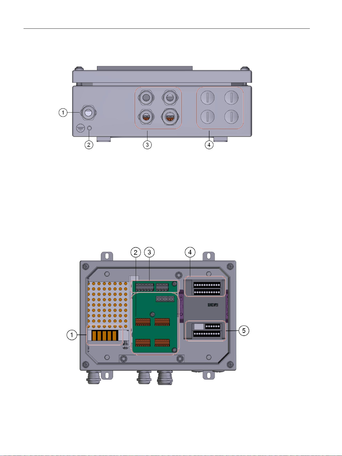
①
Stainless steel enclosure
②
SIMATIC KTP400 basic color PN color touch
display
③
Fastening screws
④
Lugs for wall fastening
⑤
Connection area
6.1 Overview
6.1 Overview
The weighing terminal SIWAREX WT241 comes with a number of connection options. It is
equipped with EMC safe cable glands for the major connections (mains and load cells).
Figure 6-1 SIWAREX WT241 overview
SIWAREX WT241
Manual, 05/2015, A5E36046748A 23
Connecting
①
M16 cable gland for mains cable
② Earthing bolt
③
M16 and M20 cable glands for load cells
④
Through holes equipped with dummy plugs
for further connections
6.1 Overview
Connections at bottom side
Figure 6-2 SIWAREX WT241 bottom side with connections
Connections inside the terminal
Figure 6-3 SIWAREX WT241 inside
SIWAREX WT241
24 Manual, 05/2015, A5E36046748A

Connecting
①
Mains connection
②
Terminal board to connect load cells / belt scale, analog output, speed sensor
③
Connections to SIWAREX WP241 – premounted to ④
④
Upper terminal block SIWAREX WP241 – premounted to ③
⑤
Lower terminal block SIWAREX WP241 – Digital inputs, digital outputs, RS485
6.1 Overview
SIWAREX WT241
Manual, 05/2015, A5E36046748A 25

Connecting
WARNING
High voltage
Switch off the machine so that it is in a no-voltage condition before you open the terminal box.
WARNING
Use switch off mechanism
The device must only be operated when using a switch off mechanism. The mechansm
shall be located close to the device.
WARNING
High voltage
Varify, whether the given mains voltage is in accordance with the specified voltage of the
product (to be found on name plate and technical data) as well as with the type approval in
effect for you country.
WARNING
High voltage
The mains cable which has to be installed by end user may be damaged due to nonqualified handling.
Before commissioning the system, conduct a visual inspection and an inspection of the
protective earth conductor. Consider the specific safety standards being valid for your
country and/or other applicable regulations. Since the cable is partly located within the
product, consider also the product safety standard IEC/EN 61010-1 and the local release
respectively.
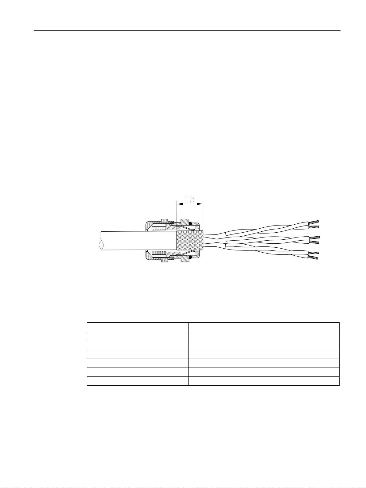
Note
Clamping range of cable glands
Use cables appropriate to the clamping range of the cable glands.
Cable gland M16 x 1.5: clamping range 6…10 mm
Cable gland M20 x 1.5: clamping range 10…14 mm
Note
Minimum wire range
Use connector cable with a minimum wire range of 0.75 mm².
6.2 Connecting to main voltage
6.2 Connecting to main voltage
SIWAREX WT241
26 Manual, 05/2015, A5E36046748A
Connecting
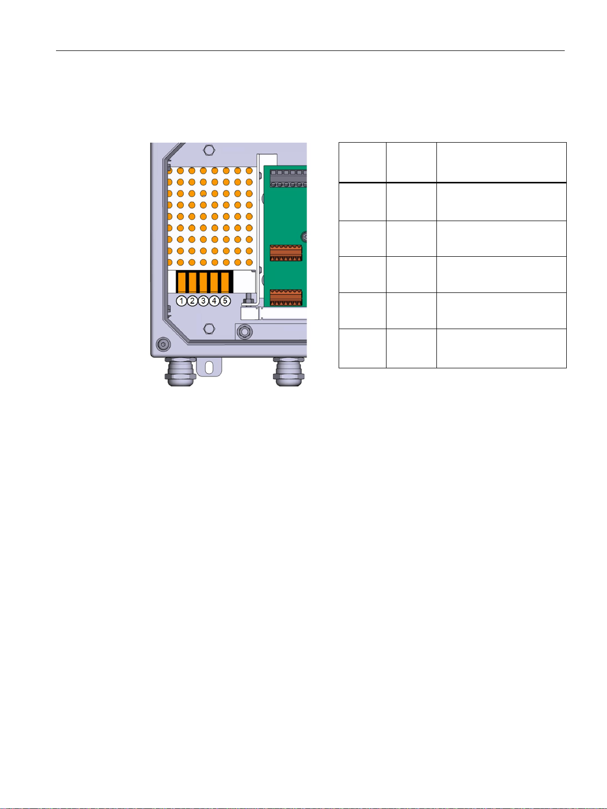
Marking
Type
Function
1
Input
Clamp for 100 ~ 240 VAC; 50
/ 60Hz – L
2
Input
Clamp for neutral wire
3
Input
Clamp for PE
4
Output
24V ground
5
Output
+24V
6.2 Connecting to main voltage
Connect the mains voltage to the premounted power supply unit in the device. Use clamps
no. 1, 2 and 3 for connecting the mains voltage.
Figure 6-4 SIWAREX WT241 power supply
SIWAREX WT241
Manual, 05/2015, A5E36046748A 27

Connecting
6.3 Connecting the load cells
6.3 Connecting the load cells
Overview
Pickups can be connected to the SIWAREX WT241 electronic weighing system which are
equipped with strain gauges (full bridge) and meet the following requirements.
● Characteristic value 1 to 4 mV/V
● A supply voltage of 5 V is permitted
● Maximum cable length between WT241 and junction box 1 000 m
The power supply for the load cells is 4.85 V.
The following condition must be satisfied in order to check the maximum possible number of
load cells which can be connected to a WT241:
● Scale operation without Ex interface: (input resistance of load cell) / (number of load
cells) > 40 Ohm
● Scale operation with Ex interface: (input resistance of load cell) / (number of load cells) >
50 Ohm
SIWAREX WT241
28 Manual, 05/2015, A5E36046748A
Connecting
Labeling
Function
Sig-
Measurement cable load cell -
Sig+
Measurement cable load cell +
Sen-
Sensor cable load cell -
Sen+
Sensor cable load cell +
Exc-
Supply load cell -
Exc+
Supply load cell +
6.3 Connecting the load cells
Rules
Observe the following rules when connecting analog (strain gauge) load cells:
1. The load cells fitted in the belt scale are connected to the PCB board implemented in the
terminal. Use the load cell connection blocks LC_A or LC_B or LC_C or LC_D to connect
the load cells. The signals will be paralleled due to the layout of the PCB. Use a wellshielded cable for the connection between belt scale and SIWAREX WT241.
2. The cable shield is always applied at the cable gland of the junction box (SIWAREX JB).
If there is a risk of equipotential bonding through the cable shield, connect an
equipotential bonding conductor parallel to the load cell cable.
3. Twisted wire pairs that are also shielded are required for the specified cables:
– Sensor cable (+) and (-)
– Measuring voltage cable (+) and (-)
– Supply voltage cable (+) and (-)
Figure 6-5 Shielding in the screw gland
We recommended that you use the cables listed in chapter → Accessories (Page 181).
Table 6- 1 Load cell connections on the module
SIWAREX WT241
Manual, 05/2015, A5E36046748A 29
Connecting
6.3 Connecting the load cells
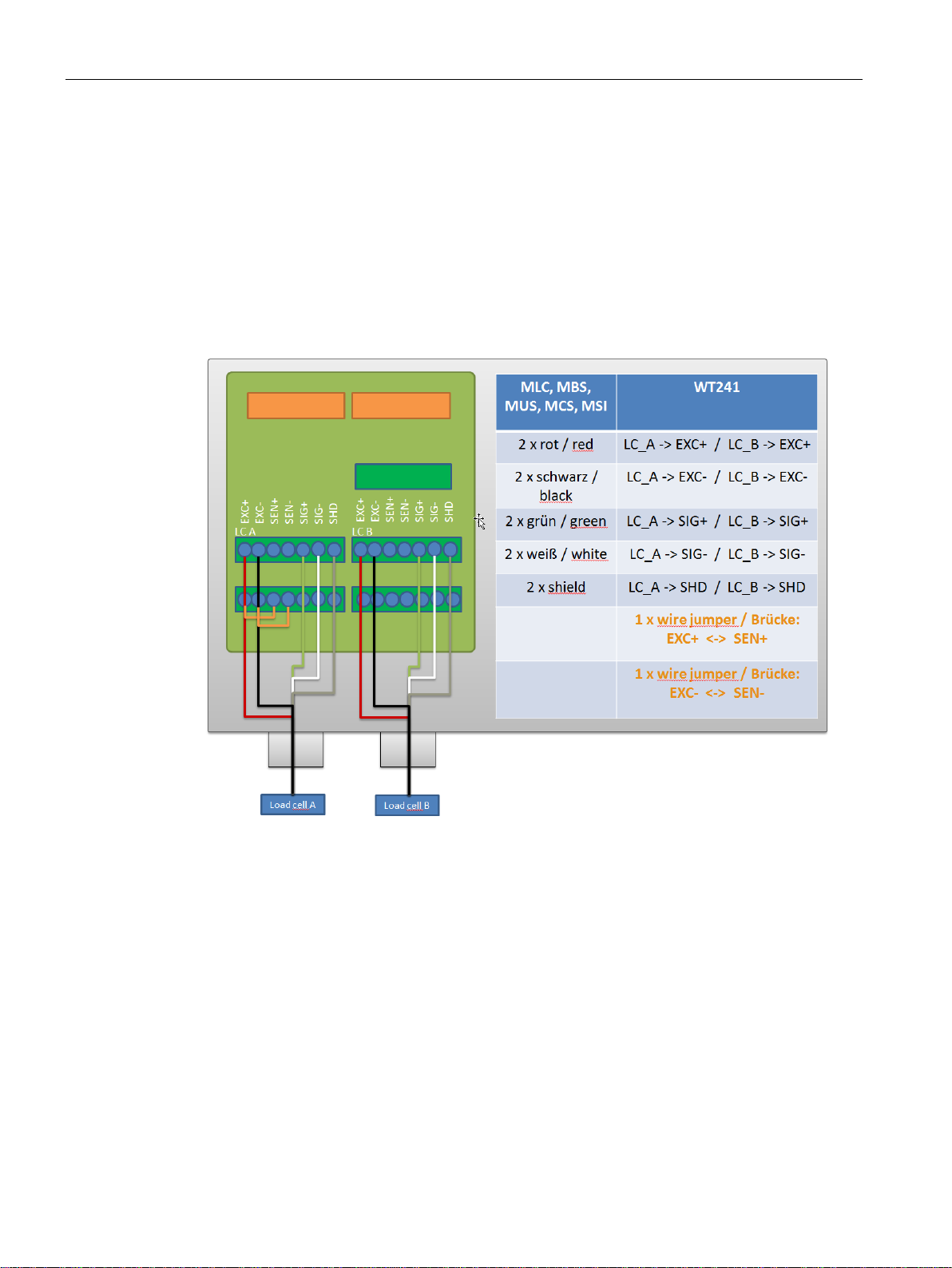
6.3.1 Connection of an MLC / MBS / MUS / MCS / MSI / MMI belt scale to WP241
The following graphic clarifies the interfacing of all Siemens belt scale types to SIWAREX
WP241. When using several MSI scales (MMI2 or MMI3) installed in sequence, all additional
load cells are connected in parallel in the junction box as shown in the graphic.
All load cells must always be connected in parallel in the junction box. With 4-wire load cells,
you must additionally set a jumper between EXC- and SEN- and between EXC+ and SEN+
in the junction box. With 6-wire load cells, the jumpers are omitted and all conductors of the
same type are connected in parallel in the junction box and directly through to the
SIWAREX.
Figure 6-6 Connecting Siemens beltscales MLC, MBS, MUS, MCS, MSU to SIWAREX WT241
SIWAREX WT241
30 Manual, 05/2015, A5E36046748A
 Loading...