

Page 1

SIWAREX WP321
___________________
___________________
___________________
___________________
___________________
___________________
___________________
___________________
___________________
___________________
___________________
___________________
___________________
___________________
___________________
___________________
Weighing systems
Electronic weighing system
SIWAREX WP321
Manual
07/2014
Introduction
1
Safety notes
2
Description
3
Application planning
4
Mounting
5
Connection
6
Commissioning
7
Scale parameters and
functions
8
Messages
9
Command lists
10
Communication in SIMATIC
S7-300/1200/1500
11
Technical data
12
Accessories
13
Appendix
A
ESD guidelines
B
List of abbreviations
C
A5E33715669A-02
Page 2
Legal information
Warning notice system
DANGER
will
WARNING
may
CAUTION
NOTICE
Qualified Personnel
personnel qualified
Proper use of Siemens products
WARNING
Trademarks
Disclaimer of Liability
This manual contains notices you have to observe in order to ensure your personal safety, as well as to prevent
damage to property. The notices referring to your personal safety are highlighted in the manual by a safety alert
symbol, notices referring only to property damage have no safety alert symbol. These notices shown below are
graded according to the degree of danger.
indicates that death or severe personal injury
indicates that death or severe personal injury
indicates that minor personal injury can result if proper precautions are not taken.
indicates that property damage can result if proper precautions are not taken.
If more than one degree of danger is present, the warning notice representing the highest degree of danger will
be used. A notice warning of injury to persons with a safety alert symbol may also include a warning relating to
property damage.
result if proper precautions are not taken.
result if proper precautions are not taken.
The product/system described in this documentation may be operated only by
task in accordance with the relevant documentation, in particular its warning notices and safety instructions.
Qualified personnel are those who, based on their training and experience, are capable of identifying risks and
avoiding potential hazards when working with these products/systems.
Note the following:
Siemens products may only be used for the applications described in the catalog and in the relevant technical
documentation. If products and components from other manufacturers are used, these must be recommended
or approved by Siemens. Proper transport, storage, installation, assembly, commissioning, operation and
maintenance are required to ensure that the products operate safely and without any problems. The permissible
ambient conditions must be complied with. The information in the relevant documentation must be observed.
All names identified by ® are registered trademarks of Siemens AG. The remaining trademarks in this publication
may be trademarks whose use by third parties for their own purposes could violate the rights of the owner.
We have reviewed the contents of this publication to ensure consistency with the hardware and software
described. Since variance cannot be precluded entirely, we cannot guarantee full consistency. However, the
information in this publication is reviewed regularly and any necessary corrections are included in subsequent
editions.
for the specific
Siemens AG
Division Digital Factory
Postfach 48 48
90026 NÜRNBERG
GERMANY
Order number: A5E33715669A
Ⓟ 12/2014 Subject to change
Copyright © Siemens AG 2014.
All rights reserved
Page 3

Table of contents
1 Introduction ............................................................................................................................................. 9
2 Safety notes .......................................................................................................................................... 11
3 Description ............................................................................................................................................ 13
4 Application planning .............................................................................................................................. 17
5 Mounting ............................................................................................................................................... 19
6 Connection ........................................................................................................................................... 25
1.1 Purpose of the manual .............................................................................................................. 9
1.2 Basic knowledge required ......................................................................................................... 9
1.3 Manual - range of validity .......................................................................................................... 9
2.1 General safety instructions ..................................................................................................... 11
2.2 IT Security ............................................................................................................................... 12
3.1 Product overview .................................................................................................................... 13
3.2 Area of application .................................................................................................................. 13
3.3 System integration in SIMATIC ............................................................................................... 13
3.4 Customer benefits ................................................................................................................... 15
3.5 Scope of delivery .................................................................................................................... 16
4.1 Functions ................................................................................................................................ 17
4.2 Parameter assignment options ............................................................................................... 18
4.2.1 Parameter assignment with the PC ........................................................................................ 18
4.2.2 Parameter assignment with the SIMATIC Panel .................................................................... 18
5.1 Installation guideline ............................................................................................................... 19
5.2 EMC-compliant setup.............................................................................................................. 20
5.2.1 Introduction ............................................................................................................................. 20
5.2.2 Possible effects of interference ............................................................................................... 20
5.2.3 Coupling mechanisms............................................................................................................. 20
5.2.4 Five basic rules for securing EMC .......................................................................................... 21
5.3 Mounting on the SIMATIC ET 200SP ..................................................................................... 23
5.4 Configuration of the hardware in SIMATIC ............................................................................. 24
6.1 24 V connection ...................................................................................................................... 26
6.2 Connecting the load cells ........................................................................................................ 26
6.3 Shield connection .................................................................................................................... 28
6.4 Connection of RS485 serial interface ..................................................................................... 29
6.5 Connection of Siebert display via RS485 ............................................................................... 30
SIWAREX WP321
Manual, 07/2014, A5E33715669A-02
3
Page 4

Table of contents
7 Commissioning ..................................................................................................................................... 31
8 Scale parameters and functions ............................................................................................................ 45
7.1 Factory-set parameters .......................................................................................................... 31
7.2 Commissioning tools .............................................................................................................. 31
7.3 5-minute quick start with the operator panel and the Ready-for-Use software ..................... 32
7.3.1 Start ........................................................................................................................................ 32
7.3.2 Factory setting of the parameters .......................................................................................... 33
7.3.3 Selecting the calibration method ............................................................................................ 34
7.3.4 Defining the calibration weights ............................................................................................. 35
7.3.5 Setting calibration points ........................................................................................................ 36
7.3.6 Calibrating the scale automatically ........................................................................................ 37
7.3.7 Performing the automatic calibration ..................................................................................... 38
7.3.8 Checking the scale following calibration ................................................................................ 38
7.4 5-minute quick start with SIWATOOL .................................................................................... 39
7.4.1 Activate service mode ............................................................................................................ 39
7.4.2 Load factory setting ................................................................................................................ 39
7.4.3 Input of required parameters .................................................................................................. 40
7.4.4 Complete automatic calibration .............................................................................................. 40
7.4.5 Receive all data...................................................................................................................... 41
7.4.6 Checking the scale following calibration ................................................................................ 41
7.5 Service with the SIWATOOL program ................................................................................... 42
7.5.1 Windows and functions of SIWATOOL .................................................................................. 42
7.5.2 Offline parameter assignment ................................................................................................ 43
7.5.3 Online parameter assignment ................................................................................................ 43
7.5.4 Available help options ............................................................................................................ 44
7.5.5 Entering parameters with SIWATOOL ................................................................................... 44
8.1 Parameters and functions ...................................................................................................... 45
8.2 DR 2 command code ............................................................................................................. 45
8.3 DR 3 calibration parameters .................................................................................................. 46
8.3.1 Scale name ............................................................................................................................ 48
8.3.2 Unit of weight ......................................................................................................................... 48
8.3.3 Gross identifier ....................................................................................................................... 48
8.3.4 Maximum weighing range ...................................................................................................... 49
8.3.5 Calibration weights 0, 1, 2 and calibration digits 0, 1, 2 ........................................................ 49
8.3.6 Scale interval .......................................................................................................................... 49
8.3.7 Automatic zero adjustment .................................................................................................... 49
8.3.8 Decimal places for process values ........................................................................................ 49
8.3.9 Maximum tare load ................................................................................................................ 49
8.3.10 Maximum negative zeroing limit ............................................................................................. 50
8.3.11 Maximum positive zeroing limit .............................................................................................. 50
8.3.12 Standstill range ...................................................................................................................... 51
8.3.13 Standstill time ......................................................................................................................... 51
8.3.14 Standstill waiting time ............................................................................................................ 52
8.3.15 Low-pass filter limit frequency ................................................................................................ 52
8.3.16 Low-pass filter number ........................................................................................................... 52
8.3.17 Mean value filter depth ........................................................................................................... 53
SIWAREX WP321
4 Manual, 07/2014, A5E33715669A-02
Page 5

Table of contents
8.4 Calibration procedure.............................................................................................................. 54
8.4.1 Calibration with calibration weights ......................................................................................... 54
8.4.2 Automatic calibration............................................................................................................... 57
8.5 DR 4 Output of calculated calibration digits ............................................................................ 58
8.5.1 Calibration digits 0, 1, 2 (calculated) ....................................................................................... 58
8.6 DR 5 zeroing memory ............................................................................................................. 59
8.6.1 Effective tare weight - from specification ................................................................................ 60
8.6.2 Effective tare weight (semi-automatic) .................................................................................... 60
8.6.3 Zero weight (semi-automatic) ................................................................................................. 60
8.6.4 Current zero tracking weight ................................................................................................... 60
8.6.5 Dead load ................................................................................................................................ 60
8.7 DR 6 limit value settings ......................................................................................................... 61
8.7.1 Limit value 1 ON, limit value 2 ON, limit value 1 OFF, limit value 2 OFF ............................... 63
8.7.2 Limit value "Empty" ON ........................................................................................................... 63
8.7.3 Delay time for limits ................................................................................................................. 64
8.8 DR 9 module information ........................................................................................................ 65
8.9 DR 10 load cell parameters .................................................................................................... 67
8.9.1 50/60 Hz toggling .................................................................................................................... 68
8.9.2 Number of support points ....................................................................................................... 68
8.9.3 Load cell characteristic value .................................................................................................. 68
8.9.4 Rated load of a load cell ......................................................................................................... 68
8.10 DR 13 RS485 parameters ...................................................................................................... 69
8.10.1 RS485 protocol ....................................................................................................................... 70
8.10.2 RS485 baud rate ..................................................................................................................... 70
8.10.3 RS485 character parity ........................................................................................................... 70
8.10.4 Decimal place for Siebert indicator ......................................................................................... 70
8.11 DR 14 SIMATIC interface parameters .................................................................................... 71
8.11.1 Selection of process value 1, 2 ............................................................................................... 72
8.12 DR 15 manual tare specification ............................................................................................. 73
8.12.1 Specification of tare weight ..................................................................................................... 73
8.13 DR 30 current process values ................................................................................................ 74
8.13.1 Gross process weight ............................................................................................................. 76
8.13.2 Net process weight ................................................................................................................. 76
8.13.3 Tare process weight ................................................................................................................ 76
8.13.4 Gross / net weight ................................................................................................................... 76
8.13.5 Gross / net weight with increased resolution (x 10)
................................................................ 76
8.13.6 Tare weight ............................................................................................................................. 76
8.13.7 Refresh counter for process values ........................................................................................ 76
8.14 DR 31 advanced current process values ................................................................................ 77
8.14.1 Unfiltered digit value ............................................................................................................... 77
8.14.2 Filtered digit value ................................................................................................................... 77
8.14.3 Refresh counter for process values ........................................................................................ 78
8.15 DR 32 Message display .......................................................................................................... 79
8.15.1 Error bytes 0 to 7 .................................................................................................................... 81
8.16 DR 34 ASCII main display value ............................................................................................. 82
8.16.1 Content of main display as ACII string .................................................................................... 83
SIWAREX WP321
Manual, 07/2014, A5E33715669A-02
5
Page 6

Table of contents
9 Messages ............................................................................................................................................. 85
10 Command lists ...................................................................................................................................... 91
11 Communication in SIMATIC S7-300/1200/1500 .................................................................................... 95
12 Technical data ..................................................................................................................................... 107
13 Accessories ......................................................................................................................................... 115
A Appendix ............................................................................................................................................. 119
B ESD guidelines .................................................................................................................................... 121
C List of abbreviations ............................................................................................................................. 123
Index ................................................................................................................................................... 125
9.1 Message types ....................................................................................................................... 85
9.2 Message paths ....................................................................................................................... 86
9.3 Evaluating messages with the help of SIWATOOL ............................................................... 86
9.4 Detecting messages with the help of FB SIWA ..................................................................... 86
9.5 Message list ........................................................................................................................... 87
9.5.1 System status message list ................................................................................................... 87
9.5.2 Technology error message list ............................................................................................... 87
9.5.3 Data and operating errors message list ................................................................................. 88
9.5.4 Messages by LEDs on the module ........................................................................................ 89
11.1 General information ............................................................................................................... 95
11.2 Structure of the program "Ready for use" .............................................................................. 95
11.3 Advantages of task sharing .................................................................................................... 96
11.4 Hardware configuration of the electronic weighing system ................................................... 97
11.5 Calling of function block ......................................................................................................... 99
11.6 Working with the function block ........................................................................................... 100
11.7 I/O interface of function block .............................................................................................. 103
11.8 Error codes of function block ............................................................................................... 103
11.9 Diagnostics messages ......................................................................................................... 104
11.10 Diagnostics interrupts .......................................................................................................... 105
11.11 Hardware interrupts ............................................................................................................. 105
12.1 Technical specifications ....................................................................................................... 107
12.2 Electrical, EMC and climatic requirements .......................................................................... 110
12.3 Approvals ............................................................................................................................. 114
A.1 Technical support ................................................................................................................. 119
B.1 ESD Guidelines .................................................................................................................... 121
C.1 List of abbreviations ............................................................................................................. 123
SIWAREX WP321
6 Manual, 07/2014, A5E33715669A-02
Page 7

Table of contents
Tables
Table 6- 1 Connection of the 24 V supply ..................................................................................................... 26
Table 6- 2 Termination of RS485 serial interface.......................................................................................... 29
Table 6- 3 Settings of Siebert display S102 .................................................................................................. 30
Table 8- 1 Assignment of data record 3 ........................................................................................................ 46
Table 8- 2 Assignment of data record 4 ........................................................................................................ 58
Table 8- 3 Assignment of data record 5 ........................................................................................................ 59
Table 8- 4 Assignment of data record 6 ........................................................................................................ 61
Table 8- 5 Assignment of data record 9 ........................................................................................................ 65
Table 8- 6 Assignment of data record 10 ...................................................................................................... 67
Table 8- 7 Assignment of data record 13 ...................................................................................................... 69
Table 8- 8 Assignment of data record 14 ...................................................................................................... 71
Table 8- 9 Selection table for process value 1,2 ........................................................................................... 72
Table 8- 10 Assignment of data record 15 ...................................................................................................... 73
Table 8- 11 Assignment of data record 30 ...................................................................................................... 74
Table 8- 12 Assignment of data record 31 ...................................................................................................... 77
Table 8- 13 Assignment of data record 32 ...................................................................................................... 79
Table 8- 14 Assignment of data record 34 ...................................................................................................... 82
Table 10- 1 Command groups of the SIWAREX WP321 ................................................................................ 93
Table 11- 1 Memory requirements of the function block ................................................................................. 95
Table 11- 2 I/O data of the function block ..................................................................................................... 103
Table 11- 3 Statuses/errors when working with the function block ............................................................... 103
Table 11- 4 Diagnostics messages ............................................................................................................... 104
Table 12- 1 Interference emission (industrial area): EN 61000-6-4 .............................................................. 111
Table 12- 2 Interference immunity (industrial environment): EN 61000-6-2 ................................................. 112
Table 12- 3 Operating conditions to IEC 60721 ............................................................................................
113
Table 12- 4 Climatic requirements ................................................................................................................ 113
Table 13- 1 Essential accessories ................................................................................................................ 115
Table 13- 2 Optional accessories .................................................................................................................. 115
SIWAREX WP321
Manual, 07/2014, A5E33715669A-02
7
Page 8

Table of contents
Figures
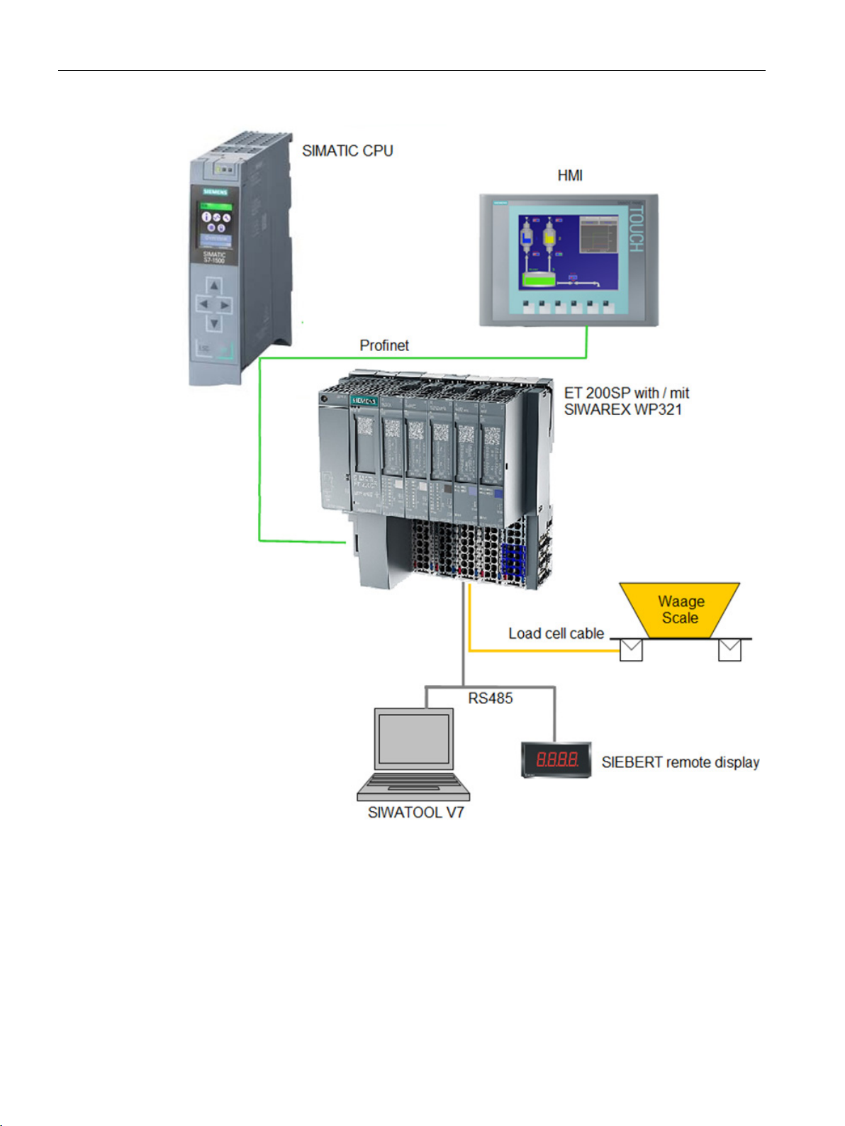
Figure 3-1 System overview .......................................................................................................................... 14
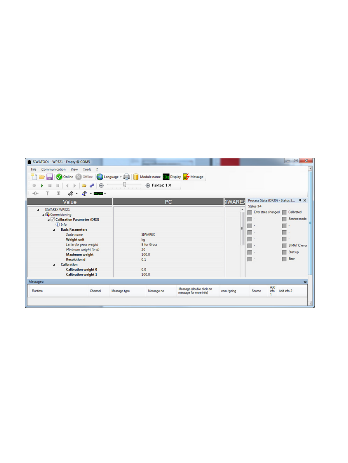
Figure 4-1 SIWATOOL overview ................................................................................................................... 18
Figure 5-1 Installation of the I/O or SIWAREX modules................................................................................ 23
Figure 6-1 SIWAREX WP321 process terminals on the base unit ................................................................ 25
Figure 6-2 Shielding in the screw gland ........................................................................................................ 27
Figure 6-3 Shield connection and shield terminal ......................................................................................... 28
Figure 6-4 Connection of Siebert display S102 ............................................................................................. 30
Figure 7-1 Quick start step 1 ......................................................................................................................... 32
Figure 7-2 Quick start step 2 ......................................................................................................................... 33
Figure 7-3 Quick start step 3 ......................................................................................................................... 34
Figure 7-4 Quick start step 4a ....................................................................................................................... 35
Figure 7-5 Quick start step 5a ....................................................................................................................... 36
Figure 7-6 Quick start step 4b ....................................................................................................................... 37
Figure 7-7 Quick start step 5b ....................................................................................................................... 38
Figure 7-8 Quick setup with marked parameters .......................................................................................... 39
Figure 7-9 Sending/receiving a data record with SIWATOOL V7 ................................................................. 40
Figure 7-10 Layout of the SIWATOOL user interface ..................................................................................... 42
Figure 8-1 Standstill monitoring ..................................................................................................................... 51
Figure 8-2 Step response of the digital low-pass filter when fg = 2 Hz ......................................................... 52
Figure 8-3 Calibration digits and calibration weight ....................................................................................... 55
Figure 8-4 Linearizing the scale's characteristic curve .................................................................................. 56
Figure 8-5 Limit value configuration .............................................................................................................. 63
Figure 11-1 Hardware configuration in the TIA Portal ..................................................................................... 97
Figure 11-2 Start address of module in TIA Portal .......................................................................................... 98
Figure 11-3 Configuration of interrupts in TIA Portal ....................................................................................... 98
Figure 11-4 HW ID of module in TIA Portal ..................................................................................................... 98
Figure 11-5
Figure 11-6 CMD command mailboxes ......................................................................................................... 100
Figure 11-7 Configuration of hardware interrupts for S7-1500 ...................................................................... 106
Figure B-1 Electrostatic voltages which an operator can be subjected to ................................................... 122
Calling of WP321DR block in user program ................................................................................ 99
SIWAREX WP321
8 Manual, 07/2014, A5E33715669A-02
Page 9

1
1.1
Purpose of the manual
1.2
Basic knowledge required
1.3
Manual - range of validity
Type designation
Order No.
as of version
Note
This manual contains all the necessary information on setting up, installing, wiring and
commissioning the SIWAREX WP321 electronic weighing system.
Knowledge of weighing technology as well as general knowledge of the SIMATIC system
including the TIA Portal are necessary in order to understand the manual.
This manual is valid for:
SIWAREX WP321 7MH4138-6AA00-0BA0 HW V.1 FW V. 1.0
This manual contains a description of all electronic weighing systems available at the time
the manual was published. We reserve the right to include a Product Information with the
latest information on the module.
SIWAREX WP321
Manual, 07/2014, A5E33715669A-02
9
Page 10

Introduction
1.3 Manual - range of validity
SIWAREX WP321
10 Manual, 07/2014, A5E33715669A-02
Page 11
2
2.1
General safety instructions
WARNING
Non-compliance with warning notes or non-qualified handling of the system
WARNING
Permission for installation in machines
Note
itional
Note
Failure to observe the warning notes or handling of the device/system by non-qualified
personnel can result in serious injury or damage to property. This means only qualified
personnel are permitted to handle this device/system.
Start-up/commissioning is absolutely prohibited until it has been ensured that the machine
in which the component described here is to be installed fulfills the
regulations/specifications of Machinery Directive 89/392/EEC.
The specifications of the manual for the SIMATIC ET 200SP system apply for configuration,
installation and commissioning in the SIMATIC environment. This chapter includes add
information on hardware configuration, installation and preparation for operation of the
SIWAREX WP321.
The safety notes must be observed.
The device was developed, manufactured, tested and documented in compliance with the
relevant safety standards. The device does usually not pose any risks of material damage or
personal injury.
SIWAREX WP321
Manual, 07/2014, A5E33715669A-02
11
Page 12

Safety notes
2.2
IT Security
2.2 IT Security
Siemens provides automation and drive products with industrial security functions that
support the secure operation of plants or machines. They are an important component in a
holistic industrial security concept. With this in mind, our products undergo continuous
development. We therefore recommend that you keep yourself informed with respect to our
product updates. Detailed technical information can be found at:
http://support.automation.siemens.com (http://www.siemens.de/automation/csi_en_WW).
To ensure the secure operation of a plant or machine it is also necessary to take suitable
preventive action (e.g. cell protection concept) and to integrate the automation and drive
components into a state-of-the-art holistic industrial security concept for the entire plant or
machine. Products used from other manufacturers should also be taken into account here.
You will find further information under:
http://www.siemens.com/industrialsecurity (http://www.siemens.com/industrialsecurity).
SIWAREX WP321
12 Manual, 07/2014, A5E33715669A-02
Page 13

3
3.1
Product overview
3.2
Area of application
3.3
System integration in SIMATIC
SIWAREX WP321 is a versatile and flexible weighing module that can be operated as a
static weighing instrument.
The electronic weighing system can be used in SIMATIC ET 200SP and uses all features of
a modern automation system, such as integrated communication, operation and monitoring,
the diagnostics system as well as the configuration tools in the TIA Portal or SIMATIC Step7
and WinCC flexible.
The electronic weighing system described here is the perfect solution for applications in
which signals from weighing or force sensors are acquired and processed. The
SIWAREX WP321 is a very accurate electronic weighing system.
It can be used in almost all industrial weighing applications not requiring official calibration.
Use in potentially explosive atmospheres (with Ex interface SIWAREX IS) it's also possible.
The electronic weighing system described here is a technology module for
SIMATIC ET 200SP. It can be used as desired in the configuration of the automation
solution, including the weighing application. You can create optimal solutions for small and
medium-sized plants by combining the suitable SIMATIC modules. You can create
customized or industry-specific solutions in no time with the help of the configuration
package available under the "Ready for use" application for SIMATIC.
Solutions are possible with S7-300, S7-1200 as well as S7-1500 CPUs. TIA Portal or Step 7
Classic can be used as the configuration software.
SIWAREX WP321
Manual, 07/2014, A5E33715669A-02
13
Page 14
Description
3.3 System integration in SIMATIC
Figure 3-1 System overview
SIWAREX WP321
14 Manual, 07/2014, A5E33715669A-02
Page 15

Description
3.4
Customer benefits
3.4 Customer benefits
The electronic weighing system described here is characterized by decisive advantages:
● Uniform design technology and consistent communication in SIMATIC ET 200SP
● Parameter assignment by means of an operator panel, STEP7 user program or PC
● Uniform configuration option in the SIMATIC TIA Portal or SIMATIC Step7
● Measuring of weight with a resolution of up to +/- 2 million parts
● High accuracy 0.05%
● High measuring rate of 100 Hz
● Limit monitoring
● Flexible adaptation to varying requirements
● Easy adjustment of the scale using the SIWATOOL program
● Automatic calibration is possible without the need for calibration weights
● Module replacement is possible without recalibrating the scale
● Use in Ex Zone 2 / ATEX approval
● Intrinsically safe load cell supply for Ex Zone 1 (SIWAREX IS option)
● Diagnostics functions
SIWAREX WP321
Manual, 07/2014, A5E33715669A-02
15
Page 16

Description
3.5
Scope of delivery
Note
3.5 Scope of delivery
The scope of supply consists of the SIWAREX WP321 weighing module. Required
accessories → Accessories (Page 115)
The SIWAREX WP321 configuration package is required for configuration of the
SIWAREX WP321 electronic weighing system → Accessories (Page 115). The configuration
package is not included in the scope of delivery of the module.
SIWAREX WP321
16 Manual, 07/2014, A5E33715669A-02
Page 17

4
4.1
Functions
P
The primary task of the electronic weighing system is the measurement and registration of
the current weight value. The integration in SIMATIC gives you the option to process the
weight value directly in the PLC (
The SIWAREX WP321 is calibrated at the factory. This allows for automatic calibration of the
scale without the need for calibration weights and replacement of modules without the need
for recalibrating the scale.
A PC for setting the parameters of the electronic weighing system can be connected via the
RS485 interface.
The SIWAREX WP321 electronic weighing system can also be used in potentially explosive
atmospheres (Zone 2). The load cells are supplied intrinsically safe in Zone 1 applications
when you use the optional Ex interface SIWAREX IS.
rogrammabelLogic Controller).
SIWAREX WP321
Manual, 07/2014, A5E33715669A-02
17
Page 18
Application planning
4.2
Parameter assignment options
4.2.1
Parameter assignment with the PC
4.2.2
Parameter assignment with the SIMATIC Panel
4.2 Parameter assignment options
You can set the scale parameters with the convenience of the familiar Windows interface by
using the "SIWATOOL" PC parameter assignment software.
You can use the program for commissioning the scale without any knowledge of automation
technology. When servicing is required, you can analyze and test the processes in the scale
independently of the automation system or Operator Panel with the help of the PC. You can
read out the diagnostic buffer from the SIWAREX module to assist you in the event analysis.
The figure below illustrates the structure of the individual program windows.
Figure 4-1 SIWATOOL overview
SIWATOOL does not only offer support when you set the scale but also when you analyze
the diagnostic buffer that can be saved after being read out of the module together with the
parameters. The display of the current scale status can be configured.
You can switch between several languages in the program.
You require an RS485/USB converter (see Accessories (Page 115)).
SIWAREX WP321
18 Manual, 07/2014, A5E33715669A-02
SIWAREX WP321 parameters can be assigned using a SIMATIC Panel connected to the
SIMATIC CPU. The "Ready-for-use" application software is used for this.
Page 19

5
5.1
Installation guideline
When assembling the SIMATIC components together with the electronic weighing system
described here, the setup, installation and wiring guidelines for the SIMATIC ET 200SP must
be observed (see system manual "SIMATIC ET 200SP, ET 200SP distributed I/O system",
order no.: A5E03576848).
This manual describes additional installation and wiring aspects specific to the electronic
weighing system.
SIWAREX WP321
Manual, 07/2014, A5E33715669A-02
19
Page 20

Mounting
5.2
EMC-compliant setup
5.2.1
Introduction
EMC
5.2.2
Possible effects of interference
5.2.3
Coupling mechanisms
5.2 EMC-compliant setup
The electronic weighing system described here was developed for use in industrial
environments and complies with high EMC requirements. It ensures safe operation even in
harsh environmental conditions. Nevertheless, you should still carry out EMC planning
before installing your devices in order to determine any sources of interference and include
them in your considerations.
EMC (electromagnetic compatibility) describes the capability of electrical equipment to
operate without errors in a given electromagnetic environment, without being subject to
external influence and without influencing external devices in any way.
Electromagnetic interferences can influence the electronic weighing system described here
in various ways:
● Electromagnetic fields having a direct influence on the system
● Interferences transported by communication cables
● Interferences having an effect via process cables
● Interferences entering the system via the power supply and/or protective ground
Interferences can impair the fault-free functioning of the electronic weighing system.
Depending on the propagation medium (conducted or non-conducted) and the distance
between the interference source and the device, interferences can enter the faulty device
through four different coupling mechanisms:
● Electrical coupling
● Capacitive coupling
● Inductive coupling
● Radiation coupling
SIWAREX WP321
20 Manual, 07/2014, A5E33715669A-02
Page 21

Mounting
5.2.4
Five basic rules for securing EMC
Rule 1: Large area grounding contact
Rule 2: Proper cable routing
Rule 3: Fixing the cable shielding
Rule 4: Special EMC measures
5.2 EMC-compliant setup
Observe these five basic rules to secure EMC.
● When installing the devices, make sure that the surfaces of inactive metal parts are
properly bonded to chassis ground (see following sections).
● Bond all inactive metal parts to chassis ground, ensuring large area and low-impedance
contact (large cross-sections).
● When using screw connections on varnished or anodized metal parts, support contact
with special contact washers or remove the protective insulating finish on the points of
contact.
● Wherever possible, avoid the use of aluminum parts for ground bonding. Aluminum
oxidizes very easily and is therefore less suitable for ground bonding.
● Provide a central connection between chassis ground and the ground/protective
conductor system.
● Organize your wiring system into cable groups (high-voltage/power
supply/signal/measurement/data cables).
● Always route high-voltage and data cables in separate ducts or in separate bundles.
● Install the measurement cables as close as possible to grounded surfaces (e.g.
supporting beans, metal rails, steel cabinet walls).
● Ensure proper fixation of the cable shielding.
● Always use shielded data cables. Always connect both ends of the data cable shielding to
ground on a large area.
● Keep unshielded cable ends as short as possible.
● Always use metal/metalized connector housings only for shielded data cables.
● All inductors that are to be controlled should be connected with suppressors.
● For cabinet lighting in the immediate range of your controller, use interference
suppressed fluorescent lamps.
SIWAREX WP321
Manual, 07/2014, A5E33715669A-02
21
Page 22

Mounting
Rule 5: Homogeneous reference potential
5.2 EMC-compliant setup
● Create a homogeneous reference potential and ground all electrical equipment.
● Use sufficiently dimensioned equipotential bonding conductors if potential differences
exist or are expected between your system components. Equipotential bonding is
absolutely mandatory for applications in hazardous areas.
SIWAREX WP321
22 Manual, 07/2014, A5E33715669A-02
Page 23

Mounting
5.3
Mounting on the SIMATIC ET 200SP
5.3 Mounting on the SIMATIC ET 200SP
The electronic weighing system described here is a module of the SIMATIC ET 200SP
series and can be directly connected to the automation system's bus system. The 15 mm
wide module has very low installation and cabling requirements.
The module is snapped onto the ET 200SP base unit (BU). You must use base units of type
A0 (→ Accessories (Page 115)).
The load cells, power supply and serial interfaces are connected via the terminal box.
Figure 5-1 Installation of the I/O or SIWAREX modules
SIWAREX WP321
Manual, 07/2014, A5E33715669A-02
23
Page 24

Mounting
5.4
Configuration of the hardware in SIMATIC
5.4 Configuration of the hardware in SIMATIC
A station has a maximum width of 1 m, and you can use up to 64 modules depending on the
type of PN head-end, or up to 15 modules with the Profibus version. Observe the system
conditions when planning the configuration.
Each SIWAREX electronic weighing system requires 16 bytes of the I/O area. Address
assignment is carried out in the TIA Portal or in the SIMATIC Manager during hardware
configuration.
SIWAREX WP321
24 Manual, 07/2014, A5E33715669A-02
Page 25
6
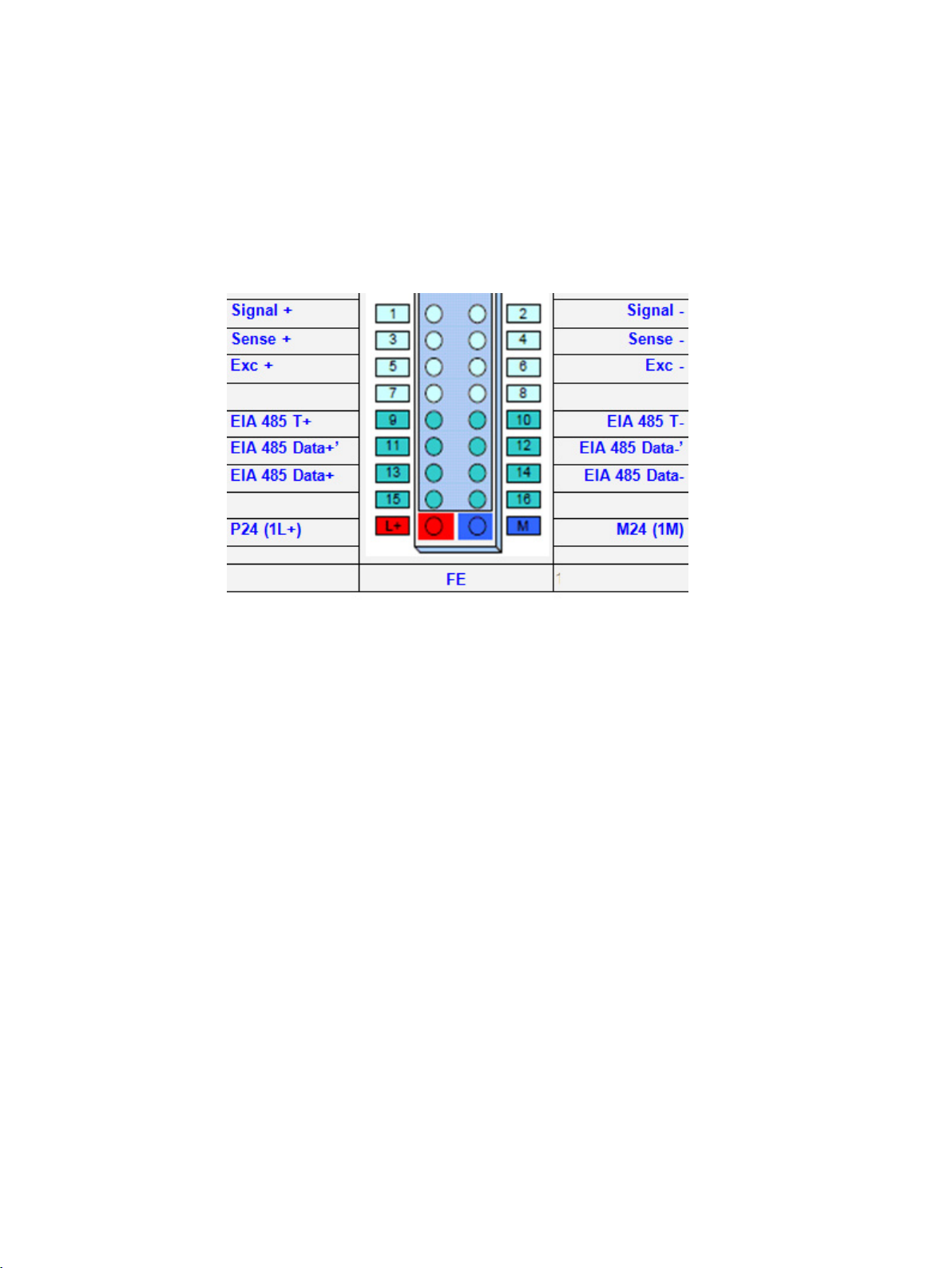
All external connections are made via the terminal box.
Figure 6-1 SIWAREX WP321 process terminals on the base unit
SIWAREX WP321
Manual, 07/2014, A5E33715669A-02
25
Page 26

Connection
6.1
24 V connection
Labeling
Function
6.2
Connecting the load cells
Observe the following rules for connection of analog (DMS) load cells
6.1 24 V connection
The 24 V DC supply voltage is connected by means of the corresponding terminals on the
base unit.
Table 6- 1 Connection of the 24 V supply
L + +24 V voltage supply
M Ground voltage supply
Pickups can be connected to the SIWAREX WP321 electronic weighing system which are
equipped with strain gauges (full bridge) and meet the following requirements.
● Characteristic value 1 to 4 mV/V
● A supply voltage of 5 V is permitted
The power supply for the load cells is 4.85 V.
1. The use of a junction box (SIWAREX JB junction box) is required when more than one
load cell is connected (the load cells must be connected in parallel). If the distance of a
load cell to the SIWAREX WP321 or the junction box is greater than the available length
of the load cell connection cable, use the SIWAREX EB extension box.
2. The cable shield is always applied at the cable gland of the junction box (SIWAREX JB)
or the extension box. If there is a risk of equipotential bonding through the cable shield,
connect a equipotential equalization conductor parallel to the load cell cable.
SIWAREX WP321
26 Manual, 07/2014, A5E33715669A-02
Page 27
Connection
Labeling
Function
Connection pin
6.2 Connecting the load cells
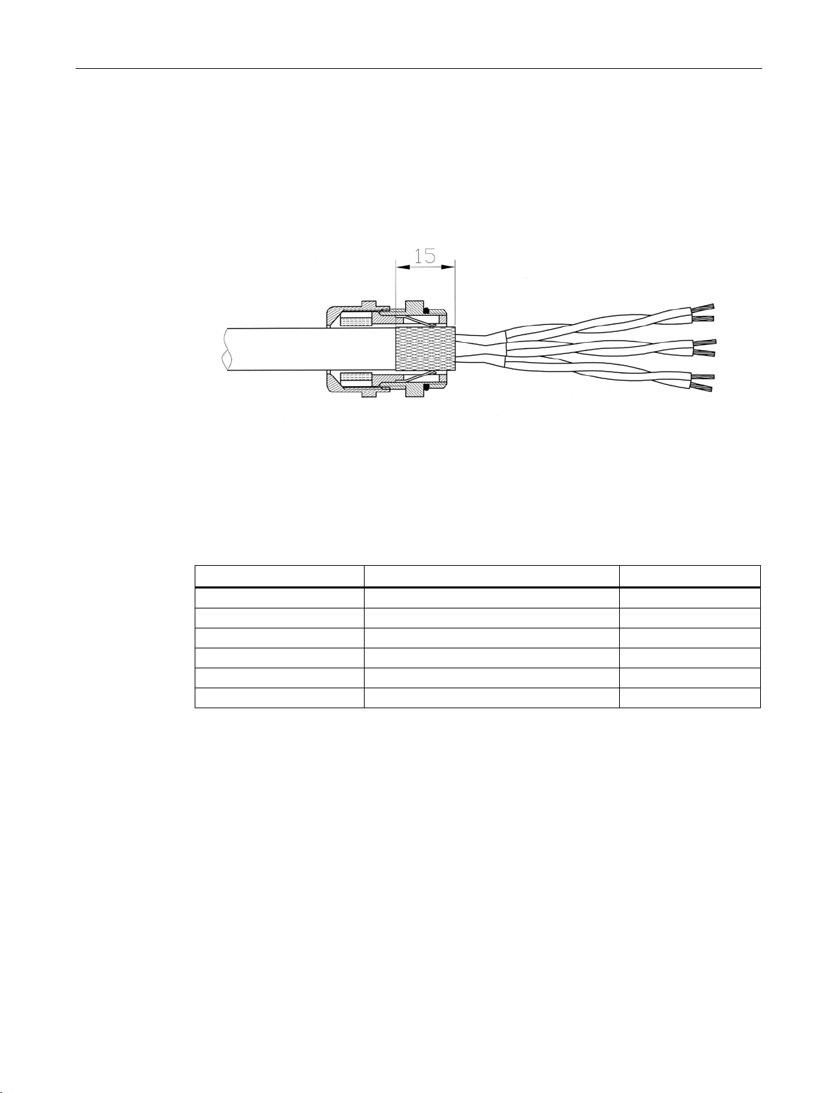
3. Twisted wire pairs that are also shielded are required for the specified cables:
– Sensor cable (+) and (-)
– Measuring voltage cable (+) and (-)
– Supply voltage cable (+) and (-)
Figure 6-2 Shielding in the screw gland
We recommended that you use the cables listed in chapter Accessories (Page 115).
4. The shield must be applied to the ground in close proximity to the SIWAREX WP321.
The maximum distance between the SIWAREX WP321 and the load cell is relevant when
you use the recommended cables.
Sig- Measurement cable load cell - 2
Sig+ Measurement cable load cell - 1
Sen- Sensor cable load cell - 4
Sen+ Sensor cable load cell + 3
Exc- Supply load cell - 6
Exc+ Supply load cell + 5
SIWAREX WP321
Manual, 07/2014, A5E33715669A-02
27
Page 28
Connection
6.3
Shield connection
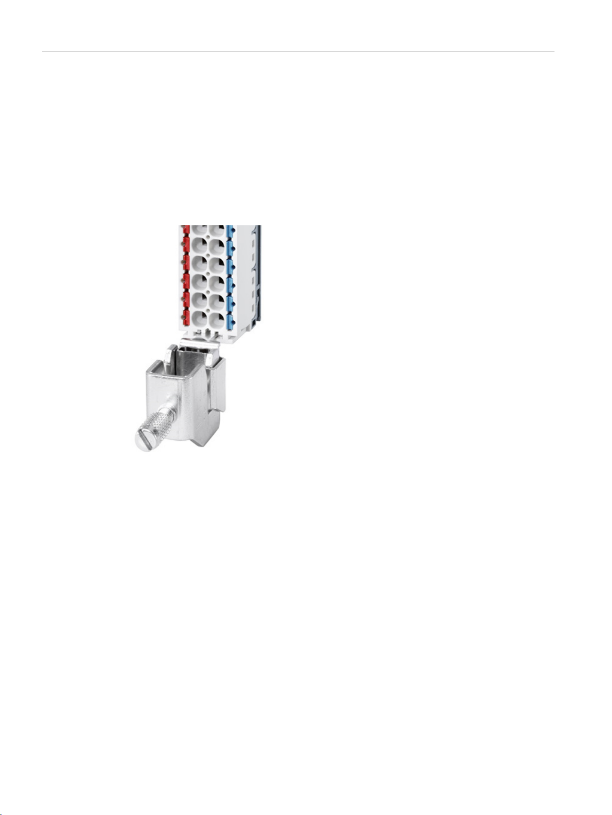
6.3 Shield connection
Make sure you observe the correct design of the shield support for the shielded cables. It is
the only way to ensure immunity of the system.
A cable is shielded to attenuate the effects of magnetic, electrical and electromagnetic
interference on the cable. Interference currents on cable shielding are diverted to ground by
conductive isolation rails. To avoid interference as a result of these currents, it is imperative
to provide a low-impedance connection to the ground.
Only use cables equipped with a shielding braid. Shielding density must be at least 80%.
Figure 6-3 Shield connection and shield terminal
SIWAREX WP321
28 Manual, 07/2014, A5E33715669A-02
Page 29

Connection
6.4
Connection of RS485 serial interface
Labeling
Function
Connection pin
mination jumpers and in between for looping through the
mination jumpers and in between for looping through the
6.4 Connection of RS485 serial interface
The following devices can be connected to the serial interface:
● Siebert display type S102 (connections: see chapter Connection of Siebert display via
RS485 (Page 30))
● PC with RS485/USB converter (see accessories) for use of SIWATOOL
Table 6- 2 Termination of RS485 serial interface
RS485: T+ RS485 termination +:
Is used at the physical end of the bus for inserting termination jumpers
RS485: T- RS485 termination -:
Is used at the physical end of the bus for inserting termination jumpers
RS485: D+' RS485 data line +':
Is used at the physical end of the bus for inserting ter-
bus cables
RS485: D-' RS485 data line -':
Is used at the physical end of the bus for inserting ter-
bus cables
RS485: D+ RS485 data cable + 13
RS485: D- RS485 data cable - 14
9
10
11
12
If a SIWAREX WP321 module is connected to SIWATOOL or a Siebert display, insert wire
jumpers between the T+ and D+' terminals and between the T- and D-' terminals.
SIWAREX WP321
Manual, 07/2014, A5E33715669A-02
29
Page 30
Connection
6.5
Connection of Siebert display via RS485
Menu item
Setting
Meaning
485
Address
Weight value
2
0.0
----*
8.8.8
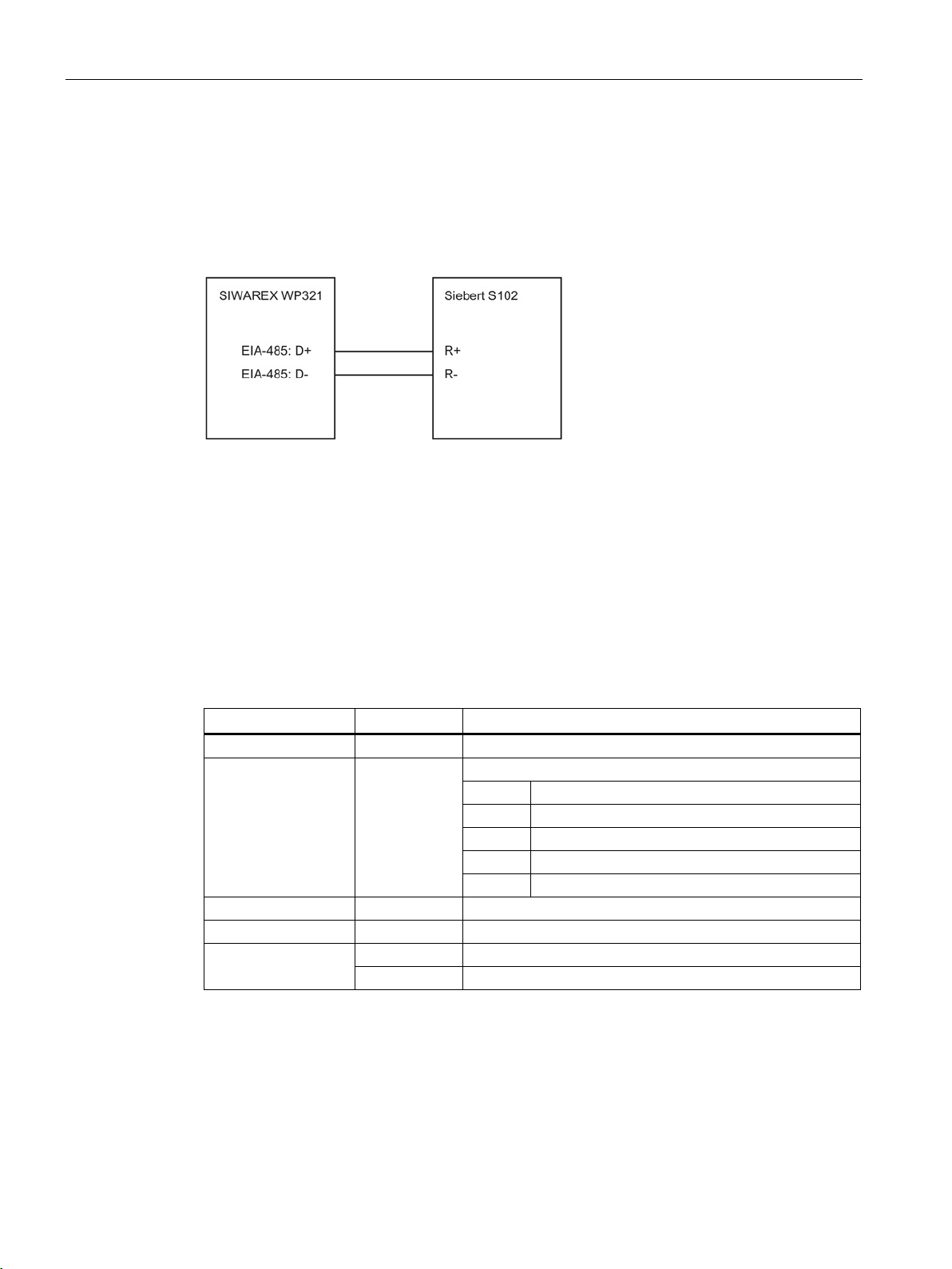
6.5 Connection of Siebert display via RS485
A Siebert display S102 with the order no. S102-W6/14/0R-000/0B-SM can be connected to
the RS485 interface of the weighing module. Connect a 24 V DC supply to the Siebert
display, and connect the latter to the RS485 interface of the weighing module as shown in
the following diagram.
Figure 6-4 Connection of Siebert display S102
The RS485 interface in the DR13 of the SIWAREX WP321 is set as follows:
● Baud rate: 9 600 bit/s
● Character parity: Even
● Number of data bits: 8
● Number of stop bits: 1
The S102 is set as follows:
Table 6- 3 Settings of Siebert display S102
1 Interface
9 Station address
t Timeout
C
F Segment test
01
RS485 interface
Address meaning:
01 Weight
02 Total
03 Net
04 Tare
e.g. timeout after 2 seconds
No decimal point
No segment test when switching on
Segment test when switching on
SIWAREX WP321
30 Manual, 07/2014, A5E33715669A-02
Page 31

7
7.1
Factory-set parameters
7.2
Commissioning tools
Commissioning essentially comprises:
● Checking the scale construction
● Specifying the parameters
● Calibration
● Verifying the envisaged functionality
The electronic weighing system described here is provided with factory-set parameters. The
parameters have been provided for a typical 100 kg scale based on three load cells.
Parameters which can be entered in % or time are preset in such a way that they provide
good results for most applications.
With these default parameters, commissioning can be carried out in 5 minutes (see chapter
5-minute quick start with the operator panel and the Ready-for-Use software (Page 32)).
The following options are available for commissioning the electronic weighing system:
● Operator panel via SIMATIC CPU
● SIWATOOL
If the SIWAREX is only connected to the ET 200SP station, commissioning of the scale can
be carried out using the SIWATOOL program. Operator panel and automation system are
unnecessary. In the event of a fault, additional SIWATOOL diagnostics functions enable fast
analysis of the cause.
SIWAREX WP321
Manual, 07/2014, A5E33715669A-02
31
Page 32

Commissioning
7.3
5-minute quick start with the operator panel and the Ready-for-Use
software
7.3.1
Start
7.3 5-minute quick start with the operator panel and the Ready-for-Use software
The 5-minute quick start is carried out in this example using a TP700 Comfort Panel
connected to the SIMATIC CPU. The panel communicates with the SIWAREX module via
the SIMATIC CPU.
To carry out the quick start, select the "1.0 Setup" function in the main menu and then "1.2
Quick Start". You will be guided through the individual tasks for setting the most important
parameters.
The remaining parameters are factory-set in such a way that they can be used in most cases
without any changes.
Figure 7-1 Quick start step 1
SIWAREX WP321
32 Manual, 07/2014, A5E33715669A-02
Page 33

Commissioning
7.3.2
Factory setting of the parameters
7.3 5-minute quick start with the operator panel and the Ready-for-Use software
The quick start is based on the factory setting of the parameters. Therefore, the previous
parameter settings must be reset prior to the quick setup. Service mode must be switched on
first. Resetting to the factory setting can then be carried out.
Figure 7-2 Quick start step 2
SIWAREX WP321
Manual, 07/2014, A5E33715669A-02
33
Page 34

Commissioning
7.3.3
Selecting the calibration method
7.3 5-minute quick start with the operator panel and the Ready-for-Use software
Figure 7-3 Quick start step 3
The module can always be calibrated in two different ways:
● Using reference weights: in the case of a calibration with weights, mechanical influences
of the scale construction are also partially taken into account.
● Without weights, using the technical specifications of the connected load cell(s): in the
case of automatic calibration, the accuracy of the scale is influenced by the mechanical
properties to a greater extent than with calibration using reference weights.
With both methods, make sure that the mechanical properties of the scale are flawless prior
to calibration.
SIWAREX WP321
34 Manual, 07/2014, A5E33715669A-02
Page 35

Commissioning
7.3.4
Defining the calibration weights
7.3 5-minute quick start with the operator panel and the Ready-for-Use software
Figure 7-4 Quick start step 4a
In step 4 you enter the calibration weights which are to be positioned on the scale during the
calibration. If the scale is not empty and the current contents are known, you can define an
"Calibration weight 0" with the current contents of the scale. With an empty scale, this
parameter remains as 0 kg. "Calibration weight 1" usually defines the first reference point of
the scale characteristic. A further reference point ("Calibration weight 2") can also be set in
addition. This is optional, and may not be necessary depending on the mechanical properties
of the scale.
Note that the interval between the calibration weights must be at least 2% of the nominal
load of the scale. With a 1 000 kg scale, a calibration weight of at least 20 kg must therefore
be used.
SIWAREX WP321
Manual, 07/2014, A5E33715669A-02
35
Page 36
Commissioning
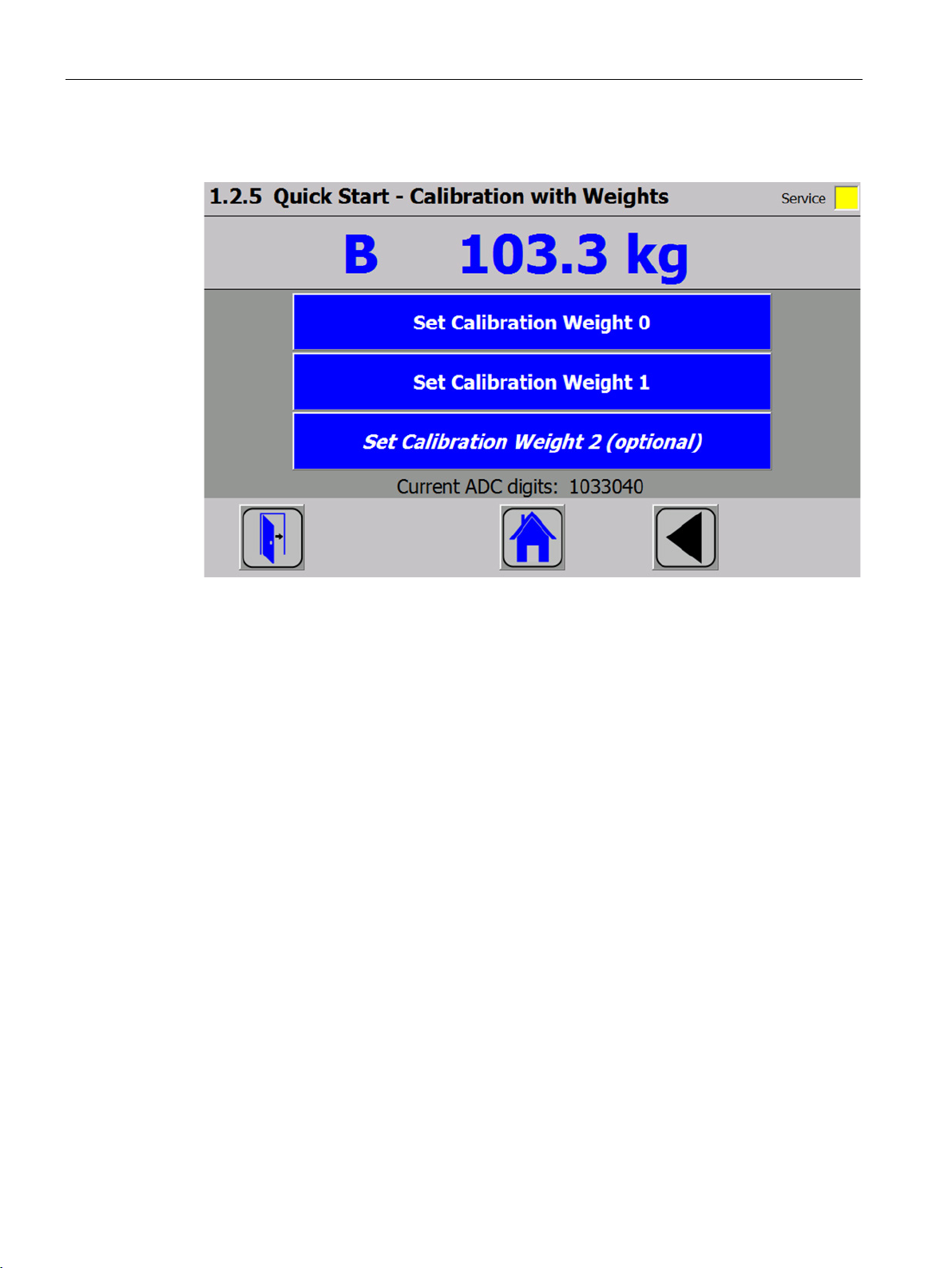
7.3.5
Setting calibration points
7.3 5-minute quick start with the operator panel and the Ready-for-Use software
Figure 7-5 Quick start step 5a
Carry out the calibration commands at the end of the quick start:
1. Carry out the "Set calibration weight 0" command. The "Calibration weight 0" defined in
step 4 is now visible in the display.
2. Place the "Calibration weight 1" defined in step 4 on the scale construction, and execute
the "Set calibration weight 1" command.
3. If an "Calibration weight 2" was selected:
Place "Calibration weight 2" defined in step 4 on the scale construction, and execute the
"Set calibration weight 2" command.
4. Calibration of the scale is now complete. Return to the start screen by clicking on the
house icon.
SIWAREX WP321
36 Manual, 07/2014, A5E33715669A-02
Page 37

Commissioning
7.3.6
Calibrating the scale automatically
7.3 5-minute quick start with the operator panel and the Ready-for-Use software
The scale can also be calibrated without weights. To do this, it is necessary to enter data
specific to the load cells. In addition, it is essential that the scale is empty.
Figure 7-6 Quick start step 4b
The number of points of support corresponds with a silo, for example, to the number of
clamps or feet of the silo. A quadratic platform scale with a load cell at each corner has 4
support points. The characteristic values of the individual load cells are required to calculate
the average characteristic value of the cells.
The equation for the calculation is as follows:
(characteristic of cell 1 + characteristic of cell 2 + characteristic of cell n) / n
If the exact characteristic values are unknown, it is permissible to also use rounded-off
numbers (e.g. 1.0 mV/V, 2.0 mV/V). The nominal load of an individual load cell (not the
nominal load of the complete scale!) must subsequently be defined.
SIWAREX WP321
Manual, 07/2014, A5E33715669A-02
37
Page 38
Commissioning
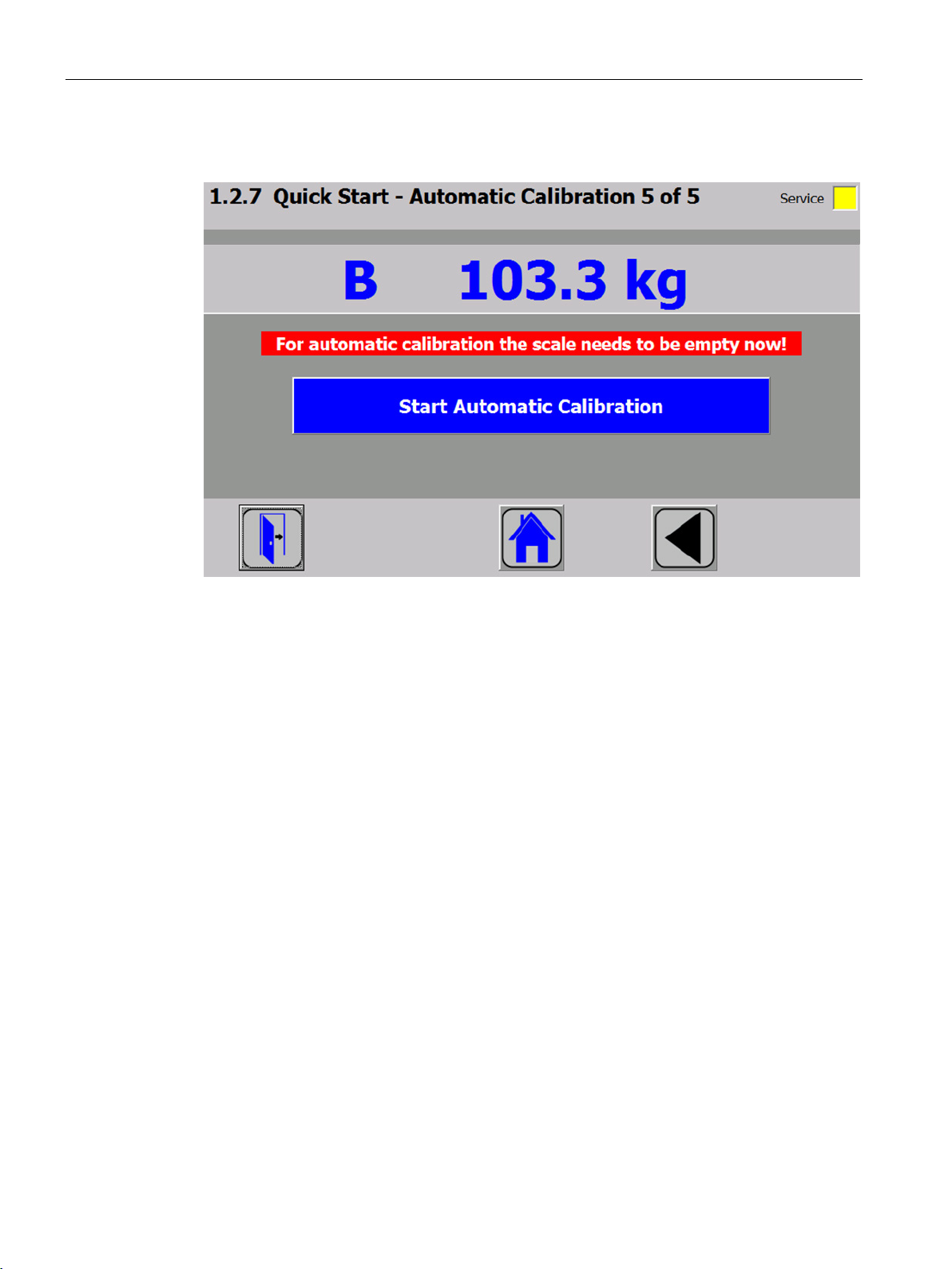
7.3.7
Performing the automatic calibration
7.3.8
Checking the scale following calibration
7.3 5-minute quick start with the operator panel and the Ready-for-Use software
Figure 7-7 Quick start step 5b
Subsequently enter the "Perform automatic calibration" command with the scale empty. The
scale is calibrated directly, and clicking on the house icon returns you to the start screen.
If the scale is only used for company-internal purposes, a simple check is sufficient.
Perform the following steps:
1. The scale is unloaded and shows "0 kg".
2. Place a known reference weight on the scale.
Check the displayed value.
3. If a second known reference weight is available, place it on the scale in addition.
Check whether the scale displays the sum of the reference weights.
4. Remove the reference weights from the scale.
Check that the display is "0 kg" again.
SIWAREX WP321
38 Manual, 07/2014, A5E33715669A-02
Page 39

Commissioning
7.4
5-minute quick start with SIWATOOL
7.4.1
Activate service mode
7.4.2
Load factory setting
7.4 5-minute quick start with SIWATOOL
General information on using the SIWATOOL program can be found in chapter "Service with
the SIWATOOL program (Page 42)".
For the quick setup, the required parameters are marked in bold font in data records DR 3
and DR 10. The procedure is described below.
Figure 7-8 Quick setup with marked parameters
Service mode must be activated in order to change the calibration parameters. You can find
the command in the "Service Commands" group (spanner icon).
The quick setup is based on the standard settings of the weighing module. The factory
setting must therefore be reset prior to the quick start. Firstly, service mode is activated; the
factory setting is subsequently loaded using the "Load factory setting (11)" command.
SIWAREX WP321
Manual, 07/2014, A5E33715669A-02
39
Page 40

Commissioning
7.4.3
Input of required parameters
7.4.4
Complete automatic calibration
7.4 5-minute quick start with SIWATOOL
For commissioning, you must enter the following parameters in data record DR 3 and send
these to the module:
● Unit of weight
● Required maximum weighing range of the scale
● Scale interval
Sending/receiving a data record is always carried out by right-clicking on the data record
name in the "Value" column in the tree structure.
For example, if data record 3 is to be sent, right-click on "Calibration parameter (DR3)". A
submenu is then opened with the option for sending the respective data record to the
weighing module or for reading it from the module. All data records can only be sent as
complete packets to the SIWAREX or read from it. It is not possible to read or write individual
parameters within a data record. Therefore the complete data record must initially be
received for every change to parameters within it. The desired parameter can then be edited,
and the data record returned. If the data record is not received, the danger exists that
different offline parameters will be sent to the scale and overwrite previously active and
intentionally defined parameters.
Figure 7-9 Sending/receiving a data record with SIWATOOL V7
You must subsequently enter the required parameters in data record DR 10 and send these
to the module.
● Number of support points
● Characteristic value of a load cell in mV/V, or the mean value of the characteristic values
if there is more than one load cell
● Rated load of a load cell
● The scale must be empty (only mechanical dead load).
● Activate the "Automatic Calibration 82" command.
SIWAREX WP321
40 Manual, 07/2014, A5E33715669A-02
Page 41

Commissioning
7.4.5
Receive all data
7.4.6
Checking the scale following calibration
7.4 5-minute quick start with SIWATOOL
Activate the "Receive all data" function in the communication menu.
All parameters can now been saved as a backup file on the hard disk. If a module is
replaced, the backup file can be downloaded to the new module within a few seconds. At the
time of input of the backup file, the scale is directly in the calibrated state again – without a
new calibration.
If the scale is only used for company-internal purposes, a simple check is sufficient.
Perform the following steps:
1. The scale is unloaded and shows "0 kg".
2. Place a known reference weight on the scale.
Check the displayed value.
3. If a second known reference weight is available, place it on the scale in addition.
Check whether the scale displays the sum of the reference weights.
4. Remove the reference weights from the scale.
Check that the display is "0 kg" again.
SIWAREX WP321
Manual, 07/2014, A5E33715669A-02
41
Page 42

Commissioning
7.5
Service with the SIWATOOL program
See also
7.5.1
Windows and functions of SIWATOOL
①
③
②
④
7.5 Service with the SIWATOOL program
You can use the SIWATOOL program to commission the scale independently of the
SIMATIC automation system. You require an RS485/USB converter (see section
"Accessories") in order to connect the PC to the SIWAREX. You can then connect the
RS485 interface of the SIWAREX to the USB port of the PC.
The SIWATOOL program is included in the configuration package.
Install the SIWATOOL program (SIWATOOL catalog) on your PC for commissioning.
Accessories (Page 115)
Control elements for SIWATOOL and operation of
the scale
Parameter list of the SIWATOOL module
Figure 7-10 Layout of the SIWATOOL user interface
For sending, receiving and transferring, select the corresponding data record and call the
command list with a right mouse click.
The complete data record (all parameters of the data record) is always transferred, not just
individual parameters.
SIWAREX WP321
42 Manual, 07/2014, A5E33715669A-02
Offline values of the SIWAREX module
Online values of the connected SIWAREX module
Page 43

Commissioning
7.5.2
Offline parameter assignment
7.5.3
Online parameter assignment
Note
7.5 Service with the SIWATOOL program
All scale parameters can be edited and saved without an electronic weighing system.
This reduces the setup time. You can thus prepare the parameters for several scales in your
office, and subsequently transfer them to the electronic weighing system during setup.
Data from one scale currently in operation can be exported and used to set up another scale.
To switch to online mode, connect the PC to the SIWAREX module via an RS485/USB
converter. Set the appropriate interface in the communication menu.
You can change all parameters in the SIWAREX module in online mode. The message
window shows the current contents of the message buffer of the SIWAREX module. The
current process values are displayed in the "Online" column.
For test purposes, you can send various commands to the SIWAREX module. Differences
between the online/offline data are marked in red by SIWATOOL. This affects both the
associated data record and the individual parameter.
In order to archive data, all data can be exported from the SIWAREX module and saved as a
file or printed.
You can edit all data in the SIWAREX module in online mode. The changes are not
automatically imported to the corresponding scale data block in the SIMATIC CPU.
To download the data to the SIWAREX module, select the data record with a right mouse
click and send it explicitly to the SIWAREX module.
Online parameter trends can be recorded and played back using the recorder function
located at the top right-hand edge of SIWATOOL. You can use the "Configure recorder"
button to select the data records to be recorded and to set the save parameters. The
playback speed can be set using a slider.
SIWAREX WP321
Manual, 07/2014, A5E33715669A-02
43
Page 44

Commissioning
7.5.4
Available help options
7.5.5
Entering parameters with SIWATOOL
7.5 Service with the SIWATOOL program
SIWATOOL offers various help options for operation:
● Info card
You can select the "Info" item directly underneath the individual data records in the
navigation tree. This info card explains how the data record influences the scale behavior.
● Tooltip
If you move the mouse over a button or parameter, a corresponding help text is
displayed.
● Help
Click on the menu option "Help" to call up the SIWATOOL help. The Help can be opened
separately.
There is a defined procedure for handling parameters. The current parameters in the
SIWAREX module are displayed in the right-hand window, while the parameter values on the
PC are displayed in the left-hand window. The new parameter value is entered first in the
left-hand window. If several parameters of the data record are to be changed, they are
entered consecutively. The data record is subsequently selected in the tree view and sent to
the SIWAREX modules using the right mouse button.
Parameters are always changed as complete data records, rather than individually.
SIWAREX WP321
44 Manual, 07/2014, A5E33715669A-02
Page 45

8
8.1
Parameters and functions
8.2
DR 2 command code
All parameters are set to default values in the factory. You can restore the configuration to
factory settings using the "Load factory settings" command.
The scales are ready for operation with the default parameter settings. You do not need to
re-enter all parameters. The advantage of this solution is that you can decide the default
values to be retain and the parameters that need to be adapted for your application.
All parameters are divided into data records (DR). The data records are organized in steps
(tasks) to be implemented during commissioning or during the process.
The scale functions governed by the parameters are also described in the parameter
description below.
First, the parameters of a given data record are displayed in a table. The detailed parameter
description for the parameters of this data record then follows.
When it receives new parameters, the SIWAREX module runs a validation check. In the
event of a parameter assignment error, the data record is not applied (not saved) by the
SIWAREX module and a data/operator error is reported.
DR 2 is a special data record used to transfer commands to the SIWAREX module by
SIWATOOL.
SIWAREX WP321
Manual, 07/2014, A5E33715669A-02
45
Page 46

Scale parameters and functions
8.3
DR 3 calibration parameters
Procedure
Variable
Note
Type
Length
(bytes)
Rw
Default
Min.
Max.
8.3 DR 3 calibration parameters
The calibration parameters need to be checked and if necessary modified for all scales.
The scale is basically defined by calibration parameters and calibration operation.
● Check all parameters and modify them as required.
● Transfer the DR 3 data record from SIWATOOL to the scale.
● Calibrate the scale.
● Transfer the DR 3 data record from the scale to SIWATOOL.
Table 8- 1 Assignment of data record 3
Data record
number
Length Data record length information USHORT 2 r 124 - Application Information about which application
Version identifier
Scale name
header
Scale name
(Page 48)
Unit of
weight header
Unit of
weight
(Page 48)1)
Gross identifier header
Gross identifier
(Page 48)
Reserve Reserve USHORT 8 rw 0 - Maximum
weighing
range
(Page 49)
Calibration
weights 0, 1,
2 and calibration digits
Contains no. of data record USHORT 2 r 3 - -
USHORT 2 r 201 - -
the DR belongs to
Information on the current data rec-
ord version
Maximum length and actual length of
string for scale name
Scale name specified by user CHAR[12] 12 rw " " - -
Maximum length and actual length of
string for unit of weight (e.g.: g, kg, t,
...)
Unit of weight CHAR[4] 4 rw "kg••" - -
Maximum length and actual length of
string for unit of weight
Abbreviation of gross
(B or G), only one byte is used!
Maximum weight FLOAT 4 rw 100 > wb_min*
1)
Calibration weight 01) (usually the
zero point)
Calibration weight 11) FLOAT 4 rw 100 1 9 999 999
Calibration weight 2 FLOAT 4 rw 0 1 9 999 999
USHORT 2 r 1 1 65 635
UBYTE[2] 2 rw 12,12 - -
UBYTE[2] 2 rw 04,04 - -
UBYTE[2] 2 rw 02,02 - -
CHAR[2] 2 rw "B" "B" "G"
ZIF.step
FLOAT 4 rw 0 1 9 999 999
maximum
number
range
SIWAREX WP321
46 Manual, 07/2014, A5E33715669A-02
Page 47

Scale parameters and functions
Variable
Note
Type
Length
(bytes)
Rw
Default
Min.
Max.
0, 1, 2
8.3 DR 3 calibration parameters
(Page 49)
Calibration digits 0 determined during calibration with calibration weight
FLOAT 4 rw 0 -3 999 999 +3 999
999
0
Calibration digits 1 determined dur-
ing calibration with calibration weight
FLOAT 4 rw 2 000 000 -3 999 999 +3 999
999
1
Calibration digits 2 determined dur-
ing calibration with calibration weight
FLOAT 4 rw 0 -3 999 999 +3 999
999
2
Scale interval
(Page 49)
Weighing range1 scale interval
1)
(1*10**k, 2*10**k, 5*10**k]; k: -3 …
FLOAT 4 rw 0,1 0.001 50
2)
Reserve Bit 1: Reserve BIT 2 rw 0 0 1
Reserve Bit 2: Reserve BIT 0 rw 0 0 1
Automatic
zero adjustment
(Page 49)
Reserve (13
Autom. zeroing device
BIT 0 rw 0 0 1
(zero tracking device)
0: Autom. zeroing off
1: Autom. zeroing on
Bit 3: Reserve BIT 0 rw 0 0 1
bits)
Decimal
places for
process
values
(Page 49)
0: No rounding
1: Rounding to 1 decimal place
2: Rounding to 2 decimal places
3: Rounding to 3 decimal places
4: Rounding to 4 decimal places
USHORT 2 rw 0 0 6
5: Rounding to 5 decimal places
6: Rounding to 6 decimal places
Maximum
tare load
Range of subtractive tare unit
[in % of max. weighing range ]
FLOAT 4 rw 0 0 250
(Page 49)
Reserve Reserve FLOAT 8 rw 1,0 0 100.0
Maximum
negative
zeroing limit
Negative range of semi-automatic
zeroing device [in % of max. weighing range]
FLOAT 4 rw 1 0 100.0
(Page 50)
Maximum
positive zeroing limit
Positive range of semi-automatic
zeroing device [in % of max. weighing range]
FLOAT 4 rw 3,0 0 100.0
(Page 50)
Standstill
range
(Page 51)
Standstill
Standstill range (in d) FLOAT 4 rw 0,1 0 maximum
number
range+
Standstill time 1 in ms TIME 4 rw 2 000 10 10 000
time
(Page 51)
SIWAREX WP321
Manual, 07/2014, A5E33715669A-02
47
Page 48

Scale parameters and functions
Variable
Note
Type
Length
(bytes)
Rw
Default
Min.
Max.
8.3.1
Scale name
8.3.2
Unit of weight
8.3.3
Gross identifier
8.3 DR 3 calibration parameters
Standstill
waiting time
(Page 52)
Low-pass
filter limit
frequency
(Page 52)
Low-pass
filter number
(Page 52)
Reserve Reserve USHORT 2 rw 0 - Reserve Reserve FLOAT 4 rw 0 tbd tbd
Reserve Reserve USHORT 2 rw 4 2 10
Mean value
filter depth
(Page 53)
1)
Parameter for calculation of calibration points
Waiting time until standstill.
0: Any scale commands dependent
on standstill are rejected immediately
in the absence of standstill.
>0: Maximum waiting time until
command is executed
Low-pass filter limit frequency:
0: Filter disabled
Filter number 2*(1…5) USHORT 2 rw 4 2 10
Filter for digit values,
permitted filter depth: 0 … 250
TIME 4 rw 2 000 0 10 000
FLOAT 4 rw 0,5 tbd tbd
USHORT 2 rw 10 0 250
You can select any name, but it may not exceed 12 characters. You can enter any
designation.
A string with up to four digits can be specified as the unit of weight, e.g.: t, kg, lbs. The
defined unit of weight applies to all weight specifications. Entries are not be converted if the
unit of weight has changed. Entries must be left-aligned.
The gross identifier specifies the letter, B (for brutto) or G (for gross), to be used in the
display for gross weights.
SIWAREX WP321
48 Manual, 07/2014, A5E33715669A-02
Page 49

Scale parameters and functions
8.3.4
Maximum weighing range
8.3.5
Calibration weights 0, 1, 2 and calibration digits 0, 1, 2
8.3.6
Scale interval
8.3.7
Automatic zero adjustment
Note
8.3.8
Decimal places for process values
8.3.9
Maximum tare load
8.3 DR 3 calibration parameters
The weight can only be used with the defined scale interval below the maximum weight (+
9 d, d = scale interval). The maximum weight is defined during commissioning. Exceeding
the maximum weight is indicated in the status (DR30).
The maximum weight depends on the number and type of load cells used.
The calibration weights and corresponding calibration digits define the characteristic curve of
the scales. A detailed description can be found in section Calibration procedure (Page 54).
The scale interval for the weighing range can be defined in accordance with EN 45501
(0.0001 to 50).
If required, you can carry out semi-automatic zeroing of the scale using the "Zeroing"
command.
The automatic adjustment sets the scale to zero without a further command in the event of
slow zero drifting. Slow drift is assumed if the OIML R76 criteria are met.
If this function is enabled, the scale may eventually read zero after a slow drift even if they
are fully loaded. The function can, however, be limited by specifying a maximum and
minimum weight for zeroing.
This parameter is used to specify the number of decimal places to which the process values
are to be rounded. This value decouples the main display of the weight values from the
values used in the control software.
The weighing module accepts any external tare specification which is less than the
maximum tare load (percentage of maximum weighing range). Tare commands are also
accepted provided that the current gross weight is less than the configured maximum tare
load.
SIWAREX WP321
Manual, 07/2014, A5E33715669A-02
49
Page 50

Scale parameters and functions
8.3.10
Maximum negative zeroing limit
8.3.11
Maximum positive zeroing limit
8.3 DR 3 calibration parameters
Zeroing defines the current weight of the scales as zero.
You can limit the effect of the zeroing function. The limitation is based not on the current
gross weight, but rather on the weight which the scales would display had there been no
zeroing (time of scale calibration).
You can limit the effect of the zeroing function. The limitation is based not on the current
weight, but rather on the weight which the scales would display had there been no zeroing
(time of scale calibration).
SIWAREX WP321
50 Manual, 07/2014, A5E33715669A-02
Page 51
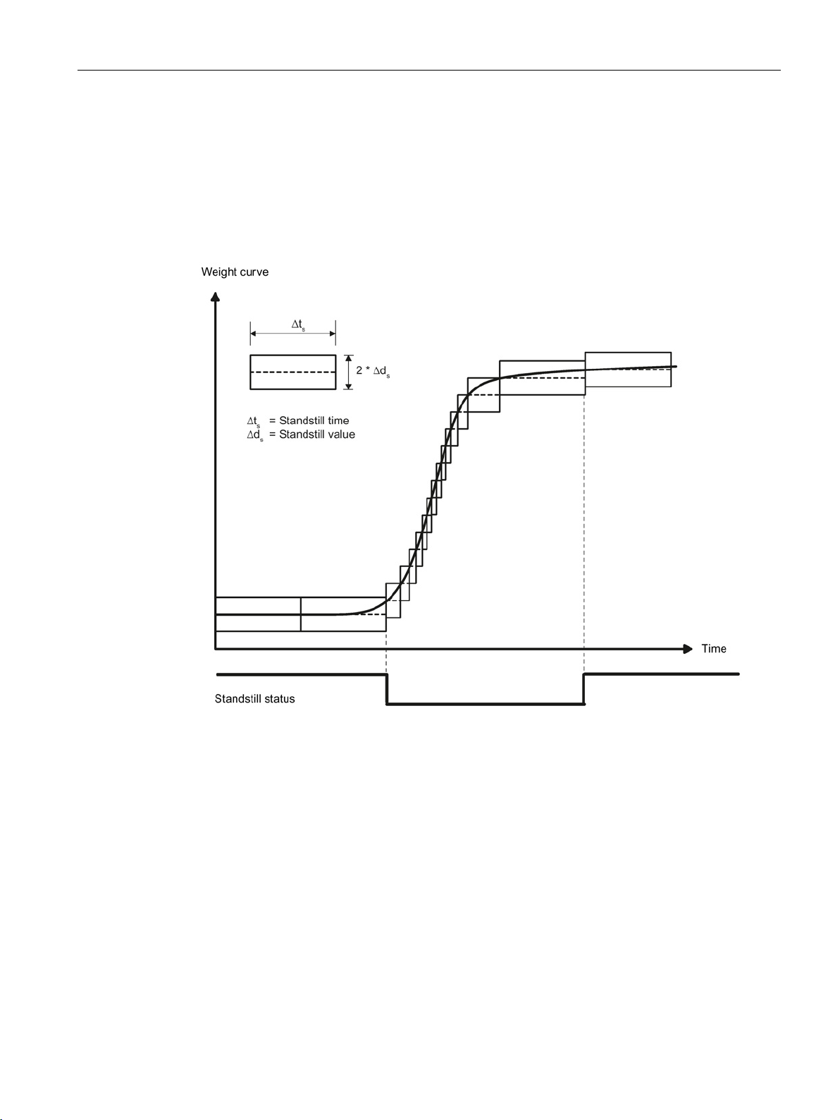
Scale parameters and functions
8.3.12
Standstill range
8.3.13
Standstill time
8.3 DR 3 calibration parameters
Standstill monitoring checks whether the scales are correctly balanced. Scale standstill is
registered if the weight changes by less than a specified fluctuation in d (standstill value)
over a specified time (standstill time). Standstill monitoring is used in static scale mode
(commands: zeroing, taring). The diagram below illustrates how standstill monitoring works.
The current weight can only be registered in legal trade applications if standstill is reached.
Figure 8-1 Standstill monitoring
SIWAREX WP321
Manual, 07/2014, A5E33715669A-02
Standstill monitoring checks whether the scales are correctly balanced. Scale standstill is
registered if the weight changes by less than a specified fluctuation in d (standstill value)
over a specified time (standstill time). Standstill monitoring is used in static scale mode (with
the following commands: zeroing, taring).
51
Page 52

Scale parameters and functions
8.3.14
Standstill waiting time
8.3.15
Low-pass filter limit frequency
8.3.16
Low-pass filter number
8.3 DR 3 calibration parameters
Standstill waiting time is a maximum waiting time for standstill on execution of a command
which depends on standstill (taring, zeroing). A technology message is generated if the
command cannot be executed during the standstill waiting time because there is no
standstill.
If the standstill waiting time is equal to zero, a command requiring standstill is rejected
immediately if there is no standstill.
There is a critically damped low-pass filter for suppressing faults. The diagram below shows
the step response of the filter (f
limit frequency of between 0.01 and 20.0 Hz can be specified.
= 2 Hz). The entry "0" means that the filter is switched off. A
g
Figure 8-2 Step response of the digital low-pass filter when f
The definition of the limit frequency is extremely important for the suppression of faults.
Defining the limit frequency defines the "speed" of the scale's response to changes in the
measured value.
A value of 5 Hz, for example, results in a relatively rapid response to a change in weight; a
value of 0.5 Hz makes the scale "slower".
SIWAREX WP321
52 Manual, 07/2014, A5E33715669A-02
The number of the filter defines the effect of damping. The values 2 and 4 can be set. The
higher the selected filter number, the higher the effect.
= 2 Hz
g
Page 53

Scale parameters and functions
8.3.17
Mean value filter depth
8.3 DR 3 calibration parameters
The mean value filter is used to steady the weight against random interference. The weight
is the mean value of n (n = max. 250) weights which are recorded by the weighing module
every 10 ms, e.g. when n = 10, the mean of 10 weights is calculated. Every 10 ms, the
oldest value is discarded and the newest value included in the calculation.
SIWAREX WP321
Manual, 07/2014, A5E33715669A-02
53
Page 54

Scale parameters and functions
8.4
Calibration procedure
8.4.1
Calibration with calibration weights
Example
Load cell characteristic value
Calibration digit 1 (ca.) when rated load is
8.4 Calibration procedure
The incoming analog measured value from the load cells is converted into a digital value in
an analog-to-digital converter. A weight is calculated using this digital value. This weight is
then used by all weighing module functions for messages and for determining the status.
The characteristic curve of the measuring system must be defined before the weight can be
calculated from the digital value. In the simplest case, the characteristic curve is defined with
points 0 and 1. The first working point (point 0) is defined by the empty scale (no load) at
their own weight. The load cells return a voltage measurement to the weighing module as a
result of the weight of the scales themselves. Following analog-to-digital conversion of the
measured voltage, the zero point is assigned to the digital value (calibration digits for the
zero point).
If the scales are loaded with a defined standard weight (e.g. 50% of the measuring range),
the new digital value returned by the analog-to-digital converter is assigned the standard
weight.
The characteristic curve can also be determined with a third point, which must be higher than
point 1.
Make sure that the difference between two calibration weights is at least 40 000 digits, as the
calibration command may otherwise be rejected.
The calibration procedure involves the following steps:
● Activation of service mode using the "Service mode on" command.
● Define the calibration weight and other parameters of the DR 3 data record.
● Transfer the DR 3 data record to the scales.
● Trigger "Adjustment weight 0 valid" for empty scales.
● Load the scale with the defined standard weight.
● Trigger "Adjustment weight 1 valid".
● Transfer data record DR 3 from the scale to SIWATOOL and save the data on a data
medium.
You must follow the correct calibration sequence with increasing calibration weights.
Zero point = 0.0 kg (always) equals 326348 digits
Calibration weight 1 = 100 kg equals 1324765 digits
1 mV/V 500 000
2 mV/V 1 000 000
4 mV/V 2 000 000
SIWAREX WP321
54 Manual, 07/2014, A5E33715669A-02
Page 55
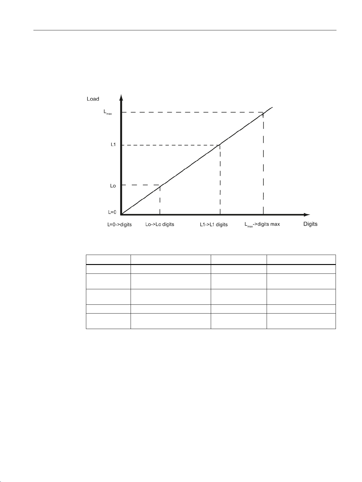
Scale parameters and functions
Load
Comment
Load
Digits
8.4 Calibration procedure
This defines the characteristic curve and the scale can now calculate weights for the full
measuring range.
The diagram below illustrates the relationship between calibration digits and the calibration
weight.
Figure 8-3 Calibration digits and calibration weight
L=0 Load cells empty Approx. 0
Lo Calibration weight 0 "Zero
point"
L1 Calibration weight 1 e.g. 60 kg e.g. 308 452 for calibration
L
Rated load of the load cell(s) e.g. 100 kg 1 000 000
max
L
+10 % Rated weight + approximately
max
10%
0 kg e.g. 70 682 for calibration
point 0
digits 1
e.g. approximately
110 kg
1 090 000
You do not need to perform calibration if the calibration digits and the calibration weights are
known to the weighing module described here. They are simply sent to SIWAREX by data
record DR 3 and the scale is ready for use immediately.
The SIWATOOL program facilitates rapid calibration.
Following commissioning and calibration, all data records must be read from the weighing
module and saved as a scale file.
SIWAREX WP321
Manual, 07/2014, A5E33715669A-02
55
Page 56

Scale parameters and functions
Note
Load
Comment
Load
Digits
8.4 Calibration procedure
Identical scales can be put into operation immediately. Connect the PC to the new scale and
enable the "Send all data records" function in service mode. This transfers the parameters
for calibration weights and calibration digits, and the characteristic curve is determined
immediately. The same applies when you change a weighing module.
Two working points are usually sufficient for determining the scale's characteristic curve. An
additional working point is only required for non-linear systems.
Specification of negative calibration points is not possible. However, the characteristic can
also be used in the negative range down to -2 000 000 digits. To achieve this, the
characteristic curve generated in the positive range is extended into the negative range.
Figure 8-4 Linearizing the scale's characteristic curve
L=0 Load cells empty Approx. 0
Lo Calibration weight 0 "Zero
point"
L1 Calibration weight 1 e.g. 60 kg e.g. 386 452 for calibra-
L2 Calibration weight 2 e.g. 80 kg e.g. 451 367 for calibra-
L
Rated load of the load cell(s) e.g. 100 kg 1 000 000
max
L
+10 % Rated weight + approximately
max
10%
SIWAREX WP321
0 kg e.g. 76 082 for calibra-
tion point 0
tion digits 1
tion digits 2
e.g. approximately 110
kg
1 090 000
56 Manual, 07/2014, A5E33715669A-02
Page 57

Scale parameters and functions
8.4.2
Automatic calibration
Note
8.4 Calibration procedure
Scales can be rapidly commissioned with automatic calibration. The accuracy of the scale
greatly depends on the entered parameters and the mechanical properties of the scale.
However, you achieve the best level of accuracy for the scales by using calibration weights.
During initial commissioning with automatic calibration, you must reset the module using the
"Load factory settings" command.
Subsequently specify the load cell parameters in data record 10. Command 82 "Perform
automatic calibration" then uses this data and the currently applied dead load to calculate the
characteristic curve of the scale. The characteristic curve is active immediately.
The characteristic curve data in data record 3 active prior to execution of command 82 is
directly overwritten.
Automatic calibration requires the following criteria:
● Correct mechanical installation of the scale
● Scale is empty (only mechanical installation (= dead load) present on the cells)
● Load cells are evenly loaded
● There are no shunt circuits
SIWAREX WP321
Manual, 07/2014, A5E33715669A-02
57
Page 58

Scale parameters and functions
8.5
DR 4 Output of calculated calibration digits
Variable
Note
Type
L
Rw
Default
Min.
Max.
8.5.1
Calibration digits 0, 1, 2 (calculated)
8.5 DR 4 Output of calculated calibration digits
Date record DR 4 outputs the digits calculated from automatic scale calibration.
This data record cannot be sent to the scale.
Table 8- 2 Assignment of data record 4
Data record number
Length Data record length
Application Information about
Version identifier Information on the
Calibration digits
0, 1, 2 (calculated)
(Page 58)
Reserve 1 Reserve SHORT 2 r 0 - Reserve 2 Reserve USHORT 2 r 0 - Reserve 3 Reserve FLOAT 4 r 0 - -
Contains no. of data
record
information
which application the
DR belongs to
current data record
version
Calibration digits 0
(calculated): Calibration digits calculated
in "Automatic Calibration"
Calibration digits 1
(calculated): Calibration digits calculated
in "Automatic Calibration"
Calibration digits 2
(calculated): Calibration digits calculated
in "Automatic Calibration"
USHORT 2 r 4 - -
USHORT 2 r 28 - -
USHORT 2 r 201 - -
USHORT 2 r 1 1 65 635
LONG 4 r ?
LONG 4 r 0
LONG 4 r 0
The calculation is based on the parameters from DR 3 and DR 10 identified by bold font and
is activated by the command no. 82.
SIWAREX WP321
58 Manual, 07/2014, A5E33715669A-02
Page 59

Scale parameters and functions
8.6
DR 5 zeroing memory
Procedure
Variable
Note
Type
L
Rw
Default
Min.
Max.
8.6 DR 5 zeroing memory
Data record DR 5 displays the current values in the tare memory and the zeroing memory.
● Check all parameters
● Transfer the data record to the scale
Table 8- 3 Assignment of data record 5
Data record
number
Length Data record length infor-
Application Information about which
Version identifier
Effective tare
weight - from
specification
(Page 60)
Effective tare
weight (semiautomatic)
(Page 60)
Reserve Reserve FLOAT 4 rw 0 - Zero weight
(semiautomatic)
(Page 60)
Current zero
tracking weight
(Page 60)
Dead load
(Page 60)
Reserve 1 Reserve SHORT 2 rw 0 - Reserve 2 Reserve USHORT 2 rw 0 - Reserve 3 Reserve FLOAT 4 rw 0 - -
Contains no. of data
record
mation
application the DR belongs to
Information on the current data record version
Current tare weight from
specification as process
value
Current tare weight from
semi-automatic mode as
process value
Current zeroing weight
(affected by zeroing)
Zero point correction
weight affected by automatic zeroing
Dead load determined
during calibration
USHORT 2 r 5 - -
USHORT 2 r 40 - -
USHORT 2 r 201 - -
USHORT 2 r 1 1 65 635
FLOAT 4 rw 0 0 Depends
on specification in
DR 3
FLOAT 4 rw 0 0 Depends
on specification in
DR 3
FLOAT 4 rw 0 Depends
on specification in
DR 3
FLOAT 4 rw 0 Depends
on specification in
DR 3
FLOAT 4 r 0 Depends
on specification in
DR 3
Depends
on specification in
DR 3
Depends
on specification in
DR 3
Depends
on specification in
DR 3
SIWAREX WP321
Manual, 07/2014, A5E33715669A-02
59
Page 60

Scale parameters and functions
8.6.1
Effective tare weight - from specification
8.6.2
Effective tare weight (semi-automatic)
8.6.3
Zero weight (semi-automatic)
8.6.4
Current zero tracking weight
8.6.5
Dead load
8.6 DR 5 zeroing memory
A tare weight can be specified in data record DR 15. You activate the specified tare weight
with a command (see command 1013). From this point on, the activated tare weight is
factored into the weight calculations. The "Delete tare" command deactivates the active tare
weight. This does not delete the specification in data record DR 15.
The corresponding command (see command 1011) applies the current gross weight as the
active tare weight. From this point on, the activated tare weight is factored into the weight
calculations. The "Delete tare" command deactivates the active tare weight.
The zero weight command (see command 1001) entered by the user sets the current gross
weight to "Zero" provided it is within the defined zero setting limits. The current gross weight
is saved as the zero weight. The zeroing weight must be within the specified range (usually
+3 / -1 % of the set zero point).
The current zero tracking weight is recorded in this parameter if automatic zero tracking is
activated.
The characteristic curve of the scales is determined during calibration. When there is no
load, the main display returns "0". The dead load is the weight of the empty scales, i.e. the
weight of the scales themselves.
SIWAREX WP321
60 Manual, 07/2014, A5E33715669A-02
Page 61

Scale parameters and functions
8.7
DR 6 limit value settings
Procedure
Variable
Note
Type
L
Rw
Default
Min.
Max.
8.7 DR 6 limit value settings
The switch-on and switch-off values for the limits are configured in data record DR 6.
● Check all parameters and modify them as required
● Transfer the data record to the scale
Table 8- 4 Assignment of data record 6
Data record
number
Length Data record length infor-
Application Information about which
Version identifier
DR 6 limit
value settings
(Page 61)
Reserve Reserve USHORT 2 rw 0 0 Limit value 1
ON (Page 63)
Reserve Reserve TIME 4 rw 0 0 maxi-
Limit value 1
OFF
(Page 63)
Reserve Reserve TIME 4 rw 0 0 maxi-
Limit value 2
ON (Page 63)
Contains no. of data record
mation
application the DR belongs to
Information on the current
data record version
Gross / net basis of limit
values 1 and 2
0: Limit value 1 and limit
value 2 are based on the
gross value
1: Limit value 1 and limit
value 2 are based on the
net value
Switch-on point for limit
value 1 (% of measuring
range)
Switch-off point for limit
value 1 (% of measuring
range)
Switch-on point for limit
value 2 (% of measuring
range)
USHORT 2 r 6 - -
USHORT 2 r 60 - -
USHORT 2 r 201 - -
USHORT 2 r 1 1 65 635
USHORT 2 rw 0 0 1
FLOAT 4 rw 0 maxi-
mum
number
range
FLOAT 4 rw 0 maxi-
mum
number
range
FLOAT 4 rw 0 maxi-
mum
number
range
maximum
number
range
mum
number
range+
maximum
number
range
mum
number
range+
maximum
number
range
SIWAREX WP321
Manual, 07/2014, A5E33715669A-02
61
Page 62

Scale parameters and functions
Variable
Note
Type
L
Rw
Default
Min.
Max.
Value
Limit values relate to
8.7 DR 6 limit value settings
Reserve Reserve TIME 4 rw 0 0 maxi-
mum
number
range+
Limit value 2
OFF
(Page 63)
Reserve Reserve TIME 4 rw 0 0 maxi-
Limit value
"Empty" ON
(Page 63)
Delay time for
limits
(Page 64)
Reserve Reserve USHORT 2 rw 0 - Reserve Reserve USHORT 2 rw 0 - Reserve Reserve FLOAT 4 rw 0 - -
Switch-off point for limit
value 2 (% of measuring
range)
Limit value "empty" ON
(always based on gross
value) (% of measuring
range)
Uniform delay time for
limits in ms
FLOAT 4 rw 0 maxi-
mum
number
range
FLOAT 4 rw 0 maxi-
mum
number
range
TIME 4 rw 0 0 maxi-
maximum
number
range
mum
number
range+
maximum
number
range
mum
number
range+
0 Gross weight
1 Net weight
The limit value "Empty" always relates to gross weight zero.
SIWAREX WP321
62 Manual, 07/2014, A5E33715669A-02
Page 63

Scale parameters and functions
8.7.1
Limit value 1 ON, limit value 2 ON, limit value 1 OFF, limit value 2 OFF
8.7.2
Limit value "Empty" ON
8.7 DR 6 limit value settings
The switch-on and switch-off points can be specified separately for each limit value as a
percentage of the measuring range. This allows both minimum and maximum value violation
monitoring with hysteresis. A delay time for switch-on and switch-off can also be specified.
Either the current net weight or the current gross weight can be selected as the reference
value for limits 1 and 2.
Maximum value monitoring is implemented with the following specifications:
● Switch-on value > switch-off value
Minimum value monitoring is implemented with the following specification:
● Switch-on value < switch-off value
The diagram below illustrates the function of limit values 1 and 2.
Figure 8-5 Limit value configuration
SIWAREX WP321
Manual, 07/2014, A5E33715669A-02
The value for the empty range is a limit value below which the weighing module registers
and returns the status "empty". The values are entered as a percentage of the measuring
range. The "Empty" limit always refers to the current gross weight in the scale.
63
Page 64

Scale parameters and functions
8.7.3
Delay time for limits
8.7 DR 6 limit value settings
If the weight reaches the specified switch value, a delay time (defined in ms) is launched.
Once the delay time is over, the limit switch changes status provided the weight still reaches
the specified switch value.
This delay time applies to the switch-on and switch-off values 1 and 2 and to the switch-on
limit for the empty value. The empty value does not have a switch-off delay.
SIWAREX WP321
64 Manual, 07/2014, A5E33715669A-02
Page 65

Scale parameters and functions
8.8
DR 9 module information
Variable
Note
Type
L
Rw
Default
Min.
Max.
8.8 DR 9 module information
No entries can be made in data record DR 9. This data record provides information on the
inner workings of the SIWAREX module. This information is used to identify the module at
the manufacturer plant (e.g. in the event of repairs). The entries in the data record are of no
importance to the user for operation.
Table 8- 5 Assignment of data record 9
Data record
number
Length Data record length information USHORT 2 r 68 - Application Information about which appli-
Version identifier
Order number
- header
Order number Order number of the module
Serial number
- header
Serial number Serial number " XXX00001" CHAR[12] 12 r " " - Firmware type
- header
Firmware type Reference V - Release
Firmware
version - 1st
position
Firmware
version - 2nd
position
Firmware
version - 3rd
position
Hardware
version number
OS version
header
OS version
(loader) designation
OS version
(loader) designation
Contains no. of data record USHORT 2 r 9 - -
USHORT 2 r 201 - -
cation the DR belongs to
Information on the current data
record version
Maximum and current string
length for the order number
7MH ..
String header UBYTE[2] 2 r 12,12 - -
String header UBYTE[2] 2 r 2,2 - -
B - Test
etc.
Version 1. USHORT 2 r 1 - -
Version 2. USHORT 2 r 0 - -
Version 3. USHORT 2 r 0 - -
ES hardware version number
(e.g. 03)
String header UBYTE[2] 2 r 2,2 - -
Reference V - Release
B - Test
etc.
e.g. version n USHORT 2 r 'V ' - -
USHORT 2 r 1 1 65 635
UBYTE[2] 2 r 16,16 - -
CHAR[16] 16 r "7MH …" - -
CHAR[2] 2 r 'V ' - -
USHORT 2 r 1 - -
CHAR[2] 2 r 'V ' - -
SIWAREX WP321
Manual, 07/2014, A5E33715669A-02
65
Page 66

Scale parameters and functions
Variable
Note
Type
L
Rw
Default
Min.
Max.
8.8 DR 9 module information
Reserve Reserve USHORT 6 r 0 - Reserve 4 0 FLOAT 4 r 0 - -
SIWAREX WP321
66 Manual, 07/2014, A5E33715669A-02
Page 67

Scale parameters and functions
8.9
DR 10 load cell parameters
Procedure
Variable
Note
Type
L
Rw
Default
Min.
Max.
8.9 DR 10 load cell parameters
The parameters of the analog load cells must be checked prior to the automatic calibration
and modified if necessary. Only the parameters identified by bold font and asterisk (*) need
be entered.
● Check the parameters and modify them as required
● Transfer the data record to the scale
● Adjust the scales
Table 8- 6 Assignment of data record 10
Data record
number
Length Data record length information USHORT 2 r 44 - Application Information about which application
Version identifier
Reserve USHORT 2 rw 1 1 6
50/60 Hz tog-
gling (Page 68)
Number of
support points
(Page 68)1)
Reserve USHORT 2 rw 0 0 0
Load cell char-
acteristic value
(Page 68)1)
Reserve FLOAT 4 rw 0
Rated load of a
load cell
(Page 68)1)
Reserve Reserve FLOAT 4 rw 0 - Reserve Reserve FLOAT 4 rw 0 - Reserve Reserve SHORT 2 rw 0 - Reserve Reserve USHORT 2 rw 0 - Reserve Reserve FLOAT 4 rw 0 - -
1)
Parameter for calculation of calibration points with theoretical calibration
Contains no. of data record USHORT 2 r 10 - -
USHORT 2 r 201 - -
the DR belongs to
Information on the current data
record version
50/60 Hz toggling USHORT 2 rw 0 0 1
Number of support points USHORT 2 rw 0 0 8
Characteristic value of the load cell
(n) [mV/V], the mean value is used
if there is more than one cell.
Rated load of a load cell FLOAT 4 rw 60 - -
USHORT 2 r 1 1 65 635
FLOAT 4 rw 2 > 0.1 10
SIWAREX WP321
Manual, 07/2014, A5E33715669A-02
67
Page 68

Scale parameters and functions
8.9.1
50/60 Hz toggling
8.9.2
Number of support points
8.9.3
Load cell characteristic value
Example
8.9.4
Rated load of a load cell
8.9 DR 10 load cell parameters
To improve the suppression of faults caused by the supply network, you can specify the
network frequency for signal filtering. The measuring rate is 100 Hz for the 50 Hz setting,
and 120 Hz for the 60 Hz setting.
If no anchor points are used, the number of support points is equal to the number of load
cells.
If anchor points are used in addition to load cells, the number of support points is equal to
the total number of load cells and fixed support points.
The load cell characteristic value is required to correctly interpret the output voltage from the
load cell. This specification is also necessary for determining load cell overload. The exact
value can be entered if the measurement log for the load cell is available. The mean value
can be entered if there is more than one load cell.
Characteristic value = 2.018 mV/V
The rated load of a load cell is required for checking the maximum weighing range of the
scales. The rated load is entered in the specified units of weight.
SIWAREX WP321
68 Manual, 07/2014, A5E33715669A-02
Page 69

Scale parameters and functions
8.10
DR 13 RS485 parameters
Procedure
Variable
Note
Type
L
Rw
Default
Min.
Max.
8.10 DR 13 RS485 parameters
The parameters which define the response of the RS485 interface are specified in data
record DR 13. If the interface is not used, the default values can be retained.
● Check the parameters and modify them as required
● Transfer the data record to the scale
Table 8- 7 Assignment of data record 13
Data record
number
Length Data record length information USHORT 2 r 24 - Application Information about which applica-
Version identifier
RS485 protocol
(Page 70)
RS485 baud
rate
(Page 70)
RS485 character parity
(Page 70)
Bit 1 BIT 0 rw 0 0 1
Bit 2 BIT 0 rw 0 0 1
Reserve (13
bits)
Reserve Reserve USHORT 2 rw 20 1 255
Decimal
place for
Siebert indicator
(Page 70)
Reserve Reserve USHORT 2 rw 0 - Reserve Reserve FLOAT 4 rw 0 - -
Contains no. of data record USHORT 2 r 13 - -
USHORT 2 r 201 - -
tion the data record belongs to
Information on the current data
record version
0: No protocol
2: SIEBERT display
0: 9 600 bps
1: 19 200 bps
2: 38 400 bps
3: 57 600 bps
4:115 000 bps
Character parity
0: Even
1: Odd
Reserve BIT 0 rw 0 0 1
Decimal place for Siebert display SHORT 2 rw 0 - -
USHORT 2 r 1 1 65 635
USHORT 2 rw 1 0 2
USHORT 2 rw 3 0 6
BIT 2 rw 0 0 1
SIWAREX WP321
Manual, 07/2014, A5E33715669A-02
69
Page 70

Scale parameters and functions
8.10.1
RS485 protocol
Value
Protocol
8.10.2
RS485 baud rate
Value
Baud rate
8.10.3
RS485 character parity
Value
Character parity
8.10.4
Decimal place for Siebert indicator
8.10 DR 13 RS485 parameters
This parameter defines the protocol for communication via the RS485 interface. The
SIWATOOL program does not require any presettings.
0 No communication/protocol
2 SIEBERT display
This parameter defines the baud rate for the RS485 interface.
0 9 600 bps
1 19 200 bps
2 38 400 bps
3 57 600 bps
4 115 000 bps
This parameter defines the character parity for the RS485 interface.
0 Even
1 Odd
A fixed decimal place must be specified if a Siebert indicator is used. The following values
are permitted: 0 ... 4
SIWAREX WP321
70 Manual, 07/2014, A5E33715669A-02
Page 71

Scale parameters and functions
8.11
DR 14 SIMATIC interface parameters
Procedure
Variable
Note
Type
L
Rw
Default
Min.
Max.
8.11 DR 14 SIMATIC interface parameters
The parameters which define the response of the SIMATIC interface are specified in data
record DR 14. It is possible to define the process values to be output on the basis of the I/O
area.
● Check the parameters and modify them as required
● Transfer the data record to the scale
Table 8- 8 Assignment of data record 14
Data record
number
Length Data record
Application Information
Version identifier
Selection of
process value 1, 2
(Page 72)
Selection of
process value 1, 2
(Page 72)
Reserve 1 Reserve SHORT 2 rw 0 0 Reserve 2 Reserve USHORT 2 rw 0 0 -
Contains no.
of data record
length information
about which
application
the DR belongs to
Information
on the current data
record version
Code for the
selection of
the process
variable to be
updated
Code for the
selection of
the process
variable to be
updated
USHORT 2 r 14 - -
USHORT 2 r 16 - -
USHORT 2 r 201 - -
USHORT 2 r 1 1 65 635
USHORT 2 rw 4 0 10
USHORT 2 rw 6 0 10
SIWAREX WP321
Manual, 07/2014, A5E33715669A-02
71
Page 72

Scale parameters and functions
8.11.1
Selection of process value 1, 2
Process value
Decimal code
From DR
Format
8.11 DR 14 SIMATIC interface parameters
The current process values can be read to the SIMATIC CPU with the DR 30 and DR 31
data records and the FB SIWA function block. The transfer of a larger data record is based
on "acyclic services". It may take several SIMATIC CPU cycles and therefore have a
negative effect on system performance.
The I/O interface of the SIWAREX module is the best option if a process value is to be
rapidly transferred to the SIMATIC CPU as soon as it is created in the SIWAREX module.
Data is applied cyclically by FB 41 and provided as a tag in the scales data block.
The relevant code from the table below must be entered to define the tag for output via the
I/O interface.
Table 8- 9 Selection table for process value 1,2
No process selected 0 - Gross process 1 30 FLOAT
Net process 2 30 FLOAT
Tare process 3 30 FLOAT
Legal trade G/N weight 4 30 FLOAT
G/N weight_x10 5 30 FLOAT
Unfiltered digit value 9 31 LONG
Filtered digit value 10 31 LONG
Refresh counter 12 30 USHORT
Async. error bits (32 bits):
Bits 0..15: operator error
Bits 16..31: technology error
15 32 LONG
SIWAREX WP321
72 Manual, 07/2014, A5E33715669A-02
Page 73

Scale parameters and functions
8.12
DR 15 manual tare specification
Procedure
Variable
Note
Type
L
Rw
Default
Min.
Max.
8.12.1
Specification of tare weight
8.12 DR 15 manual tare specification
Data recorder DR 15 is used for an external specification of a tare weight.
● Enter the tare weight
● Transfer the data record to the scale
● Enable the tare weight using command 1013
Table 8- 10 Assignment of data record 15
Data record
number
Length Data record
Application Information
Version identifier
Specification
of tare weight
(Page 73)
Reserve Reserve FLOAT 4 rw 0 0 -
Contains no.
of data record
length information
about which
application
the DR belongs to
Information
on the current data
record version
Tare specification
memory
(manual tare
value)
USHORT 2 r 15 - -
USHORT 2 r 16 - -
USHORT 2 r 201 - -
USHORT 2 r 1 1 65 635
FLOAT 4 rw 0 0 Depends on
specification
in DR 3
You can enter a tare weight. If a tare weight is to be applied, it must be enabled with the
corresponding command. The tare weight must not exceed the maximum tare load specified
in data record DR 3.
SIWAREX WP321
Manual, 07/2014, A5E33715669A-02
73
Page 74

Scale parameters and functions
8.13
DR 30 current process values
Procedure
Variable
Note
Type
L
Rw
Default
Min.
Max.
8.13 DR 30 current process values
Current states and process values in the scales can be monitored using process values and
advanced process values from data record DR 31. Monitoring selected data during
commissioning is extremely useful as it helps you to optimize parameters.
● Read data record DR 30 cyclically or on a time-triggered basis
● Display/analyze the required tags
It is not always necessary to cyclically read data record DR 30. If the relevant process tags
have already been selected in data record DR 14 (→ DR 14 SIMATIC interface parameters
(Page 71) ), they are immediately transferred via the I/O interface. In this case, these tags
and all status bits and messages are accessible without data record communication.
Table 8- 11 Assignment of data record 30
Data record
number
Length Data record length infor-
Application Information about which ap-
Version identifier
1/4d zero Set if gross is less than ±
9e max Set if the weight of the gross
Tared Set if the tare memory is not
Manual tare
set (pT)
Reserve BIT 0 r 0 - Waiting for
standstill
Standstill Set if standstill condition is
Reserve BIT 0 r 0 - Empty Set if "Empty" condition is met BIT 0 r 0 - Limit value 1 Limit value 1 has responded BIT 0 r 0 - Limit value 2 Limit value 2 has responded BIT 0 r 0 - -
Contains no. of data record USHORT 2 r 30 - -
USHORT 2 r 44 - -
mation
USHORT 2 r 201 - plication the data record belongs to
Information on the current
data record version
0.25e
weighing range is exceeded
by more than 9 display intervals (d)
equal to zero
Set if the tare memory is
assigned an external specified value
Set if module is waiting for
standstill to execute command
met
USHORT 2 r 1 1 255
BIT 2 r 0 - -
BIT 0 r 0 - -
BIT 0 r 0 - -
BIT 0 r 0 - -
BIT 0 r 0 - -
BIT 0 r 0 - -
SIWAREX WP321
74 Manual, 07/2014, A5E33715669A-02
Page 75

Scale parameters and functions
Variable
Note
Type
L
Rw
Default
Min.
Max.
8.13 DR 30 current process values
Reserve (5
bits)
DS32 error
status change
Reserve (7
bits)
Calibrated SIWAREX is calibrated BIT 0 r 0 - Service mode Service mode is enabled BIT 0 r 0 - Reserve (3
bits)
SIMATIC
connection
inactive
Startup Startup has taken place (is
Fault status Operating fault BIT 0 r 0 - Gross process
weight
(Page 76)
Net process
weight
(Page 76)
Tare process
weight
(Page 76)
Gross / net
weight
(Page 76)
Gross / net
weight with
increased
resolution (x
10) (Page 76)
Refresh coun-
ter for process
values
(Page 76)
Operating time
(hours)
Operating time
(minutes)
Reserve 3 Reserve FLOAT 4 r 0 - -
BIT 0 r 0 - -
Is set interface-specific with
each DS32 change
BIT 0 r 0 - -
BIT 0 r 0 - -
Set if no connection to the
SIMATIC exists on the part of
the application
deleted again after 5 seconds)
Gross weight (process value) FLOAT 4 r 0 - -
Net weight (process value) FLOAT 4 r 0 - -
Tare weight (process value) FLOAT 4 r 0 - -
Gross or net weight FLOAT 4 r 0 - -
Legal trade G/N weight with
10x resolution
Refresh counter incremented
by 1 if weight values have
been changed
Total operating time of the
module (hours)
Total operating time of the
module (minutes)
BIT 2 r 0 - -
BIT 0 r 0 - -
BIT 0 r 0 - -
FLOAT 4 r 0 - -
USHORT 2 r 0 - -
USHORT 2 r 0 - -
USHORT 2 r 0 - -
SIWAREX WP321
Manual, 07/2014, A5E33715669A-02
75
Page 76

Scale parameters and functions
8.13.1
Gross process weight
8.13.2
Net process weight
8.13.3
Tare process weight
8.13.4
Gross / net weight
8.13.5
Gross / net weight with increased resolution (x 10)
8.13.6
Tare weight
8.13.7
Refresh counter for process values
8.13 DR 30 current process values
The current gross weight. Values are rounded as specified in data record DR 3 with the
"Decimal places for process values" (Page 49) parameter.
The current net weight. Values are rounded as specified in data record DR 3 with the
"Decimal places for process values" (Page 49) parameter.
The current tare weight. Values are rounded as specified in data record DR 3 with the
"Decimal places for process values" (Page 49) parameter.
The current weight for the main display. The resolution corresponds to the scale interval
(Page 49) specified in data record DR 3.
The current weight for the main display in higher resolution. The resolution corresponds to
the scale interval specified in data record DR 3 x 10.
The current tare weight (scale interval from DR 3). The resolution corresponds to the scale
interval specified in data record DR 3.
Measured values are calculated every 10 ms in the SIWAREX module. A counter is
incremented by 1 each time. Once the counter reaches the value 65536, it starts again from
zero. The counter can be used as a time stamp for data record DR 30.
SIWAREX WP321
76 Manual, 07/2014, A5E33715669A-02
Page 77

Scale parameters and functions
8.14
DR 31 advanced current process values
Procedure
Variable
Note
Type
L
Rw
Default
Min.
Max.
8.14.1
Unfiltered digit value
8.14.2
Filtered digit value
8.14 DR 31 advanced current process values
Current states and process values in the scales can be monitored using advanced process
values and process values (DR 30). This data is not required for standard operation of the
scales.
Monitoring selected data during trial operation is extremely useful as it helps you to optimize
parameters.
● Read data record DR 31
● Display/analyze the required tags
Table 8- 12 Assignment of data record 31
Data record
number
Length Data record length information USHORT 2 r 24 - Application Information about which applica-
Version identifier
Unfiltered
digit value
(Page 77)
Filtered digit
value
(Page 77)
Reserve 1 SHORT 2 r 0 -100 100
Refresh
counter for
process values
(Page 78)
Reserve 2 FLOAT 4 r 0 - -
Contains no. of data record USHORT 2 r 31 - -
USHORT 2 r 201 - -
tion the data record belongs to
Information on the current data
record version
Unfiltered digit value of AD con-
verters / digital load cells
Filtered digit value of AD converters / digital load cells after dig.
filter 1
Refresh counter incremented by 1
if weight values have been
changed
USHORT 2 r 1 1 65 635
LONG 4 r 0 - -
LONG 4 r 0 - -
USHORT 2 r 0 - -
The unfiltered digit value is the internal measured value immediately before filtering.
The filtered digit value is the internal measured value immediately after filtering.
SIWAREX WP321
Manual, 07/2014, A5E33715669A-02
77
Page 78

Scale parameters and functions
8.14.3
Refresh counter for process values
8.14 DR 31 advanced current process values
Measured values are calculated every 10 ms in the SIWAREX module. A counter is
incremented by 1 each time. Once the counter reaches the value 65536, it starts again from
zero. The counter can be used as a time stamp for data record DR 31.
SIWAREX WP321
78 Manual, 07/2014, A5E33715669A-02
Page 79

Scale parameters and functions
8.15
DR 32 Message display
Variable
Note
Type
L
Rw
Default
Min.
Max.
8.15 DR 32 Message display
Data record 32 indicates all pending message bits. The bit "Error status changed" is present
in the status bits of the DR30. If this bit is set, the message area of the DR32 has been
changed.
The DR32 indicates which message has been newly added or deleted. The data record is
automatically read by the SIMATIC FB in the event of an error. Following successful reading,
the status bit is reset in DR30.
Table 8- 13 Assignment of data record 32
Data record
number
Length Data record length information USHORT 2 r 26 - Application Information about which application the
Version identifier
1000 Operator error BIT 2 r 0 0 1
Reserve - BIT r 0 0 1
1104 Undervoltage BIT r 0 0 1
Reserve - BIT r 0 0 1
1105 Overload BIT r 0 0 1
1106 Underload BIT r 0 0 1
1002 RAM error BIT r 0 0 1
1102 ADC error BIT r 0 0 1
1005 Hardware interrupt lost BIT r 0 0 1
1003 Checksum error data BIT r 0 0 1
Reserve - BIT r 0 0 1
1004 Checksum error program BIT r 0 0 1
Reserve - BIT r 0 0 1
1001 RESET / restart following error BIT r 0 0 1
Reserve - BIT r 0 0 1
Reserve - BIT r 0 0 1
2000 Technology error BIT 2 r 0 0 1
2001 Taring or zeroing timeout BIT r 0 0 1
Reserve (14
bits)
5000 Data or operating error exists BIT 2 r 0 0 1
5001 Command code or data record unknown BIT r 0 0 1
Reserve - BIT r 0 0 1
5003 Leaving calibration mode not possible BIT r 0 0 1
5004 Command or data transmission only
Contains no. of data record USHORT 2 r 32 - -
USHORT 2 r 101 - -
data record belongs to
Information on the current data record
version
- BIT r 0 0 1
available in service mode
USHORT 2 r 1 1 65 635
BIT r 0 0 1
SIWAREX WP321
Manual, 07/2014, A5E33715669A-02
79
Page 80

Scale parameters and functions
Variable
Note
Type
L
Rw
Default
Min.
Max.
8.15 DR 32 Message display
5005 Command or data transmission not
possible because service mode is active
5006 Command or data transmission not
possible because BUSY
5007 Command or data transmission not
possible because module is faulty or
ODIS is active
Reserve - BIT r 0 0 1
Reserve - BIT r 0 0 1
5101 Command is not permissible in this
operating state
5102 Command not possible because not at
standstill
5104 Command not possible because range
is exceeded
5105 Load cell parameter not plausible BIT r 0 0 1
Reserve BIT r 0 0 1
5107 Shifting characteristic not possible BIT r 0 0 1
7000 Permitted number range violated BIT 2 r 0 0 1
Reserve - BIT r 0 0 1
Reserve - BIT r 0 0 1
7002 Specifications of string lengths not plau-
sible
Reserve - BIT r 0 0 1
Reserve - BIT r 0 0 1
7006 Command only possible in test field BIT r 0 0 1
7007 The calibration weights or calibration
digits are not plausible
7008 Zeroing/zero setting or tare parameter
not plausible
7009 Standstill range / standstill wait time not
plausible
7010 Scale interval / rounding not plausible BIT r 0 0 1
7011 Filter parameter not plausible BIT r 0 0 1
7014 Time input not plausible BIT r 0 0 1
Reserve - BIT r 0 0 1
Reserve - BIT r 0 0 1
7019 RS485 parameter error BIT r 0 0 1
Reserve - USHORT 2 r 0 - Reserve - USHORT 2 r 0 - Reserve - USHORT 2 r 0 - -
BIT r 0 0 1
BIT r 0 0 1
BIT r 0 0 1
BIT r 0 0 1
BIT r 0 0 1
BIT r 0 0 1
BIT r 0 0 1
BIT r 0 0 1
BIT r 0 0 1
BIT r 0 0 1
SIWAREX WP321
80 Manual, 07/2014, A5E33715669A-02
Page 81

Scale parameters and functions
8.15.1
Error bytes 0 to 7
8.15 DR 32 Message display
In these areas, messages are represented by bits. A set bit means that the corresponding
message is activated. The message bit is set following a data or operator error and
automatically reset approximately 3 seconds later.
Message bits are analyzed by the operator panel message system.
The data/operator errors (error numbers 1xxx) are present in the first two bytes. These are
followed by two bytes with technology errors (error numbers 2xxx) and six bytes with data
and operator errors (error numbers 5xxx and 7xxx).
SIWAREX WP321
Manual, 07/2014, A5E33715669A-02
81
Page 82

Scale parameters and functions
8.16
DR 34 ASCII main display value
Variable
Note
Type
L
Rw
Default
Min.
Max.
8.16 DR 34 ASCII main display value
The ASCII weight corresponds to the value on the main display of the scales and can be
used for a supplementary display as well as the legal trade main display.
Table 8- 14 Assignment of data record 34
Data record
number
Length Data record length information USHORT 2 r 26 - Application Information about which application
Version identifier
ASCII display
string header
Content of
main display
as ACII string
(Page 83)
Contains no. of data record USHORT 2 r 34 - -
USHORT 2 r 201 - -
the DR belongs to
Information on the current data
record version
Maximum length and actual length
of string
For display of the weight value and
other current values (see below)
USHORT 2 r 1 1 65 635
UBYTE[2] 2 r 16,2 - -
CHAR[16] 16 r " " - -
SIWAREX WP321
82 Manual, 07/2014, A5E33715669A-02
Page 83

Scale parameters and functions
8.16.1
Content of main display as ACII string
Variable
Command
Value designation
Blank
Display value
Unit of weight
(from DR 3)
N: Net, B/G: Gross,
T: Tare, pT: Preset tare,
S: Sum, ...
8.16 DR 34 ASCII main display value
The following values can be displayed:
Switch on increased resolution 701
Current tare weight 705
Gross/net display 710
Net process value 714
Gross process value 715
Serial number 871
Firmware version 875
Below are some display examples. Commands are used to toggle the display values.
The values to be displayed are suppressed if a fault is present.
Weight
(Tare ≠ 0)
Neg. weight
(Tare = 0)
Weight in increased resolution
Operator error B • • • • • • I r r o r ****
Tare display activated (pt) p T • • • • • 5 0 , 5 0 •kg•
Tare display activated T • • • • • • 5 0 , 5 0 •kg•
N • • • • • 2 2 0 , 5 0 •kg•
B • • • • • • - 0 , 0 3 •t••
• • • • • • 1 0 , 0 0 3 HIGH
SIWAREX WP321
Manual, 07/2014, A5E33715669A-02
83
Page 84

Scale parameters and functions
8.16 DR 34 ASCII main display value
SIWAREX WP321
84 Manual, 07/2014, A5E33715669A-02
Page 85

9
9.1
Message types
System status messages
Data and operating errors
Technology errors
The messages in the electronic weighing system described here are divided into three types.
System status messages can be generated spontaneously at any time by an unexpected
event. They include internal and external hardware problems which can occur spontaneously
during weighing.
The data and operating errors are always a response to a command due to a plausibility
check.
These are data errors if a plausibility error has been detected in a data packet which was
sent to the module and receipt of the packet has been rejected by the module.
These are operating errors if the module cannot execute the sent command in its current
operating state.
Technology errors occur spontaneously due to the process flow of a weighing.
Status bits, on the other hand, are not messages. The status displays describe the status of
the scale during normal operation and can be monitored or evaluated at any time.
SIWAREX WP321
Manual, 07/2014, A5E33715669A-02
85
Page 86

Messages
9.2
Message paths
9.3
Evaluating messages with the help of SIWATOOL
9.4
Detecting messages with the help of FB SIWA
9.2 Message paths
You can read out the messages using different paths. You define the path for forwarding and
processing of messages during configuration.
The messages are processed for two basic purposes:
● For display or recording on an operator panel for the operator
● For linking in the control software to control specific reactions in the process.
The following message paths are possible:
● Output of the message buffer to the SIWATOOL program (takes place automatically)
● Output by means of function block as bit field in Scale data block
● Certain operating errors can be transmitted as diagnostic interrupts to the SIMATIC CPU
and evaluated by OB82
The electronic weighing system has a message buffer that can hold up to 10 entries. If the
number of messages in the message buffer exceeds 10, the oldest entry is overwritten. The
message buffer can be read out at any time with the help of SIWATOOL (menu item "Read
out all data records") and saved together with the scale parameters. This facilitates the
detection, analysis and correction of errors in the system.
All messages of the SIWAREX module can be completely detected and processed in the
controller with the help of the SIWAREX WP321 function block. The messages can be
evaluated directly in a signaling system by means of a bit signaling area in the scale data
block. The message texts are stored in the signaling system. The message text is output
when a bit becomes "1".
SIWAREX WP321
86 Manual, 07/2014, A5E33715669A-02
Page 87

Messages
9.5
Message list
9.5.1
System status message list
Operator error (code 1000 to 1999)
Error code
Description and remedy
9.5.2
Technology error message list
Technology error (code 2000 to 4999)
Error code
Description and remedy
9.5 Message list
The message list is an overview of all messages that the SIWAREX module can generate. A
message can be quickly identified by the message code (number).
1000 operating error exists 1000 Group message, at least one operating error exists.
1001 Watchdog 1001 Watchdog, error is displayed for at least 10 seconds. A seri-
1002 RAM error 1002 RAM error. An error has occurred in the memory; the memory
1003 Checksum incorrect parameter 1003 Checksum error at parameter. Critical error because the
1004 Checksum incorrect program 1004 Checksum error program code. Critical error because the
1102 ADU error 1102 AD converter error when reading in the measured value. If
1104 Undervoltage 1104 Undervoltage at sensor cables
1105 Overload 1105 Overload of scale (ca. 110%)
1106 Underload 1106 Underload of scale (ca. -10%)
ous error has occurred in the function of SIWAREX, e.g.
program error, severe electromagnetic influence on device,
etc.
Contact the SIWAREX Support if the error occurs multiple
times.
content is no longer correct. The module must be switched
off. If the error occurs again, SIWAREX is defective.
parameters are no longer safe.
program is no longer safe.
the error occurs again, make sure that the EMC recommendations are observed (chapter EMC-compliant setup
(Page 20)).
2000 Technology error exists 2000 Group message, at least one technology error exists
2001 Taring/zeroing timeout 2001 Taring of scale or set to zero is not possible because a standstill
SIWAREX WP321
Manual, 07/2014, A5E33715669A-02
was not reached during the standstill time. The command was
discarded.
87
Page 88

Messages
9.5.3
Data and operating errors message list
Data and operating errors
(code 5000 to 8999)
Error code
Description and remedy
f service mode is required to execute command or
9.5 Message list
5000 Data and operating error exists 5000 Group error, a bit is set in the data and operating error bits
5001 Command code or data record un-
known
5003 Cannot exit service mode 5003 Cannot exit service mode; calibration incomplete
5004 Command or data transmission only
available in service mode
5005 Command or data transmission not
possible because service mode is active
5006 Command or data transmission not
possible because of BUSY
5007 Command or data transmission not
possible because module is faulty or
SIMATIC CPU stop
5101 Command is not permissible in this
operating state
5102 Command not possible because
there is no standstill
5104 Command not possible because
range is exceeded
5105 Load cell parameters not plausible 5105 Load cell parameters in data record DR 10(a) or data record
5107 Characteristic cannot be moved 5107 Characteristic cannot be moved due to possibility of range
7000 Permitted number range violated 7000 The permitted number range, such as for weight values, was
7002 Specifications of string lengths not
plausible
7007 The calibration weights or calibration
digits are not plausible
7008 Zeroing or tare parameter not plausible
7009 Standstill range / standstill wait time 7009 Standstill range or standstill wait time are not plausible.
7010 Scale interval / rounding 7010 Scale interval or selection for rounding to decimal places is
7011 Filter parameters 7011 Specification of filter parameters is not plausible.
5001 Command code or data record is not known with current
application
5004 Activation o
transmit data
5005 Command can currently not be executed because service
mode is active
5006 Command can currently not be executed because module is
BUSY (data record or command transmission already active,
…)
5007 Command can currently not be executed because of a prob-
lem or SIMATIC CPU stop
5101 Command is not permissible in the current operating state
5102 Scale command (set to zero, tare, log, … ) cannot be execut-
ed because standstill is missing.
5104 Command (e.g. set to zero, tare, calibrate command) cannot
be executed because the permitted range has been exceeded.
DR 11(d) not plausible (number, supporting points, load specifications, etc.).
violation.
violated.
7002 The string header in a specified string variable is not plausi-
ble.
7007 Specifications for calibration weights or digits in data record
DR 3 are incorrect (minimum distance, reversal of incline).
7008 The specifications (data record DR 3) or tare specifications
(data record DR 15) are not plausible.
not plausible.
SIWAREX WP321
88 Manual, 07/2014, A5E33715669A-02
Page 89

Messages
9.5.4
Messages by LEDs on the module
Item
Color
Labeling
Function
Line 1
DIAG
{E}
0
Max
LC
Rx/Tx
PRW
9.5 Message list
The LEDs on the front of the SIWAREX module signal the following status and error
messages.
H1 red
H2 Green Ready
H11 yellow
H12 yellow
H13 yellow
H14 Not used
H15 yellow
H16 Not used
H17 Green
H18 Not used
H19 Green
H20 Not used
H21
H22 Not used
H23 Green
H24 Not used
H25 yellow
H26 Not used
H40 Green
System fault
Empty message
¼ d zero status
Weighing range exceeded
Load cell(s) ready for operation (LED off = load
Limit 1 responded
Service mode
Limit 2 responded
Standstill triggered
cells faulty)
EIA-RS485 communication active
Status of local 24 V supply
SIWAREX WP321
Manual, 07/2014, A5E33715669A-02
89
Page 90

Messages
9.5 Message list
SIWAREX WP321
90 Manual, 07/2014, A5E33715669A-02
Page 91

10
Command
code
Command
Description
Service
1... 99
Service commands
Calculation of scale characteristic using the load cell
The commands for the electronic weighing system described here can be transmitted by
several interfaces:
● by the Operator Panel via the controller to the SIWAREX module
● by SIWATOOL directly to the SIWAREX module
A data or command error is signaled if a command cannot be executed or if the sent data
record is rejected.
1 Service mode On Turn on service mode x
2 Service mode Off Turn off service mode x
11 Load factory setting The command resets the SIWAREX to the "Ex fac-
60 Calibration point 0 valid Calibration point 0 valid / save values for calibration
61 Calibration point 1 valid Calibration point 1 valid / save values for calibration
62 Calibration point 2 valid Calibration point 2 valid / save values for calibration
81 Characteristic shift Move calibration characteristic. The command de-
82 Perform automatic calibration
tory" status:
- All parameters and saved data are loaded with the
default values.
- All message buffers are reset.
point 0.
point 1.
point 2.
fines the current weight of the scale as the new zero
point (0 kg) and shifts the complete characteristic
without changing the gradient.
The command can be used, for example, in order to
compensate parts used for mounting calibration
weights on the scale at the end of the calibration.
parameters from data record 10. The calculated
characteristic is entered directly in data records 3
and 4 and thus immediately enabled following execution of the command. The scale must be empty
when the command is executed.
x
x
x
x
x
x
SIWAREX WP321
Manual, 07/2014, A5E33715669A-02
91
Page 92

Command lists
Command
code
Command
Description
Service
700 … 899
HMI display switching
1000 …
Basic functions for weighing commands
83 Perform calibration check The command calculates the theoretical digital val-
ues in relation to the calibration weights using the
load cell parameters from data record 10 and the
adjustment weights 0, 1 and 2 from data record 3.
These theoretical digits are output in data record 4.
The function can be used to carry out a plausibility
check for the calibration digits in data record 3
which were determined when calibrated using
standard weights.
701 Increased resolution Activate increased resolution on main display (x 10) x
705 Display current tare weight Display current tare weight on main display x
710 Activate standard display Activate standard display gross/net x
711 G/N display Display gross/net weight on main display x
712 N display
713 G display
714 N process value Display net process weight on main display x
715 B process value Display gross process weight on main display x
871 Show serial number The serial number of the module is displayed
875 Display FW version Show firmware version in current display x
1001 Set to zero Set to zero x
1011 Tare Tare x
1012 Delete tare Delete current tare weight x
1013 Tare specification valid Activate specification of tare weight x
1016 S7 tare specification valid Activate specification of S7 tare weight
The following commands can be triggered in the scale data block SCALE_DB in the area
CMD1 to CMD3:
SIWAREX WP321
92 Manual, 07/2014, A5E33715669A-02
Page 93

Command lists
Command
group
Description
Table 10- 1 Command groups of the SIWAREX WP321
1 ... 99 Commands are forwarded from the FB_SIWA via data record DR 2 to the module
(scale commands, weighing commands, log commands). The meaning of the
commands corresponds to the command list.
2000 + X Reading of a data record, X corresponds to the data record number.
Example: Data record 3 transmitted by SIWAREX module to the SIMATIC CPU →
2000 + 3 = command code 2003
4000 + X Writing of a data record, X corresponds to the data record number.
Example: Data record 3 transmitted by SIMATIC CPU to the SIWAREX module →
4000 + 3 = command code 4003
7001 Read all data records from SIWAREX into CPU (only for SIMATIC FB)
7002 Write data records 3, 4, 5, 6, 10, 13, 14 and 15 from CPU into SIWAREX (module
must be in service mode, only for SIMATIC FB)
Additional information on transmission of commands from the control program by means of
the SIMATIC interface is available in chapter Communication in SIMATIC S7-300/1200/1500
(Page 95).
SIWAREX WP321
Manual, 07/2014, A5E33715669A-02
93
Page 94

Command lists
SIWAREX WP321
94 Manual, 07/2014, A5E33715669A-02
Page 95

11
11.1
General information
FB 1, WP321DR
Read weight and status
Send commands
Send parameters
Main memory requirements in CPU
Load memory requirements in CPU
n = number of WP321 modules
11.2
Structure of the program "Ready for use"
A SIWAREX WP321 occupies 16 bytes each in the I/O areas of the CPU. Communication
between SIWAREX and SIMATIC CPU is supported by the FB.
Table 11- 1 Memory requirements of the function block
YES
YES
YES
11 600 byte + n x 1 232 byte
138 788 byte + n x 28 470 byte
The function block described above including HMI configuring can be downloaded as a
predefined example project ("Ready-for-use") from the Siemens Customer Support.
There is one program for Step 7 Classic and another for TIA Portal. The two programs each
consist of two parts:
● STEP 7 software for the SIMATIC CPU
● WinCC project (integrated in SIMATIC Manager)
All messages are saved as bit information. The message system can thus directly access
the bit fields and display the message texts.
SIWAREX WP321
Manual, 07/2014, A5E33715669A-02
95
Page 96

Communication in SIMATIC S7-300/1200/1500
11.3
Advantages of task sharing
11.3 Advantages of task sharing
The weight is calculated in the SIWAREX module like in a separate electronic weighing
system. However, thanks to integration in SIMATIC, it is possible to directly transfer the
weight value to the PLC program. This results in sensible sharing of tasks: the weighing
functions are performed in the SIWAREX module, while interlocking and signal linking are
performed in the PLC.
SIWAREX "Ready for use" takes over the task of a standardized program in the SIMATIC
S7.
An FB handle several tasks:
● It controls communication between the SIMATIC CPU and the SIWAREX module
● It transfers commands and adjustment values to the SIWAREX module according to the
process trend
● It prepares the scale data for visualization
SIWAREX WP321
96 Manual, 07/2014, A5E33715669A-02
Page 97
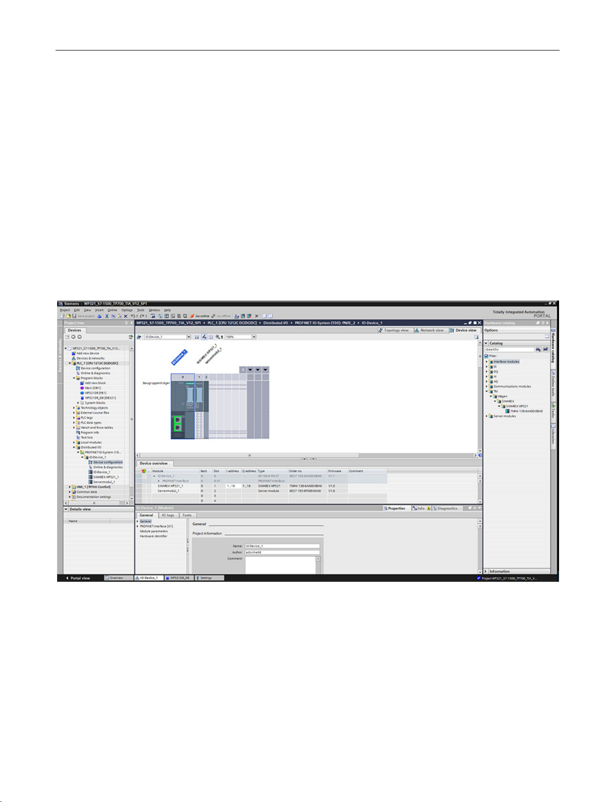
Communication in SIMATIC S7-300/1200/1500
11.4
Hardware configuration of the electronic weighing system
11.4 Hardware configuration of the electronic weighing system
The SIWAREX WP321 module can be found in the directory PLC/SIMATIC S71200/technology modules/weighing modules of the hardware catalog.
The following basic properties of the module are defined during hardware configuration in the
TIA Portal. Note that the SIWAREX WP321 module is always completely in the process
image of the CPU.
● Installation location of the module
● Address in I/O area
● Diagnostics interrupts
● Hardware interrupts
● I&M (Identification & Maintenance) data
The electronic weighing system occupies 16 bytes in the input/output area.
Figure 11-1 Hardware configuration in the TIA Portal
TIA Portal automatically assigns a separate I/O start address and a HW ID for every
SIWAREX present in the project. These two parameters are relevant for calling the function
block, and can be obtained from the properties of the respective module.
SIWAREX WP321
Manual, 07/2014, A5E33715669A-02
97
Page 98

Communication in SIMATIC S7-300/1200/1500
11.4 Hardware configuration of the electronic weighing system
Figure 11-2 Start address of module in TIA Portal
Diagnostics interrupts can be optionally enabled or deactivated in the module properties. The
configuration scope for diagnostics and hardware interrupts depends on the SIMATIC CPU
used (S7-300, S7-400, S7-1200 or S7-1500) → Diagnostics interrupts (Page 105) and
Hardware interrupts (Page 105)
Figure 11-3 Configuration of interrupts in TIA Portal
Figure 11-4 HW ID of module in TIA Portal
SIWAREX WP321
98 Manual, 07/2014, A5E33715669A-02
Page 99
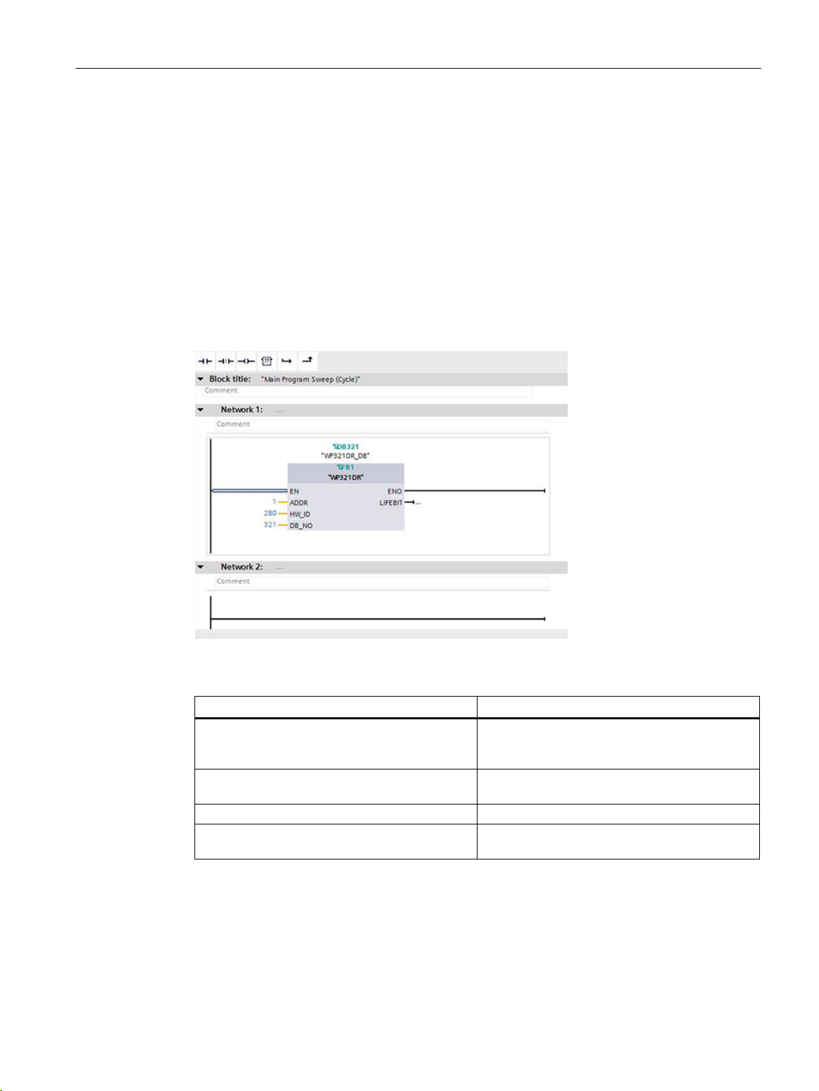
Communication in SIMATIC S7-300/1200/1500
11.5
Calling of function block
Start address
HW ID
Instance data block number
Function block parameter
Description
ADDR
HW_ID
DB_NO
LIFEBIT
11.5 Calling of function block
This description is based on use of the WP321DR block with data record communication and
the following data:
●
SIWAREX WP321: 1 (see → Hardware configuration of the electronic
weighing system (Page 97))
●
SIWAREX WP321: 280 (see → Hardware configuration of the electronic weighing
system (Page 97))
●
of SIWAREX WP321 function block: DB321
The function block can be integrated at the desired position in the user program using drag
and drop. Calling of the FB must be carried out cyclically in the control program.
SIWAREX WP321
Manual, 07/2014, A5E33715669A-02
Figure 11-5 Calling of WP321DR block in user program
Start address WP321 (see → Hardware configu-
ration of the electronic weighing system
(Page 97))
HW ID WP321 (see → Hardware configuration of
the electronic weighing system (Page 97))
Number of FB-internal instance DB
Optional status bit can be used to monitor com-
munication
The generated instance DB (WP321 in this case) contains all data records of the WP321 as
well as all parameters required to exchange data between CPU and weighing module.
A separate FB call must be made in the user program for each weighing module. In this
manner, each scale receives its own instance DB which provides the respective scale
parameters. The input and output parameters of the FB must be matched to the respective
WP321 for each call.
99
Page 100

Communication in SIMATIC S7-300/1200/1500
11.6
Working with the function block
Data records in SIWAREX weighing modules
11.6 Working with the function block
All parameters in SIWAREX weighing modules are structured in data records. These data
records must be considered as connected packages and can only be respectively read into
the CPU or written to the SIWAREX as complete packages. Reading or writing of a single
parameter within a data record is not possible. You can find a description of all data records
and their parameters in chapter → Scale parameters and functions (Page 45).
Reading and writing of data records is carried out using special command codes which can
be sent with three command mailboxes handled according to priority within the instance DB:
Figure 11-6 CMD command mailboxes
As shown in the graphics, a command mailbox always consists of a command code (Int) and
four bits (Bool). A command is set by entering the desired command code in the
"i_CMD_CODE" parameter and setting the respective command trigger
"bo_CMD_TRIGGER". The status bits "bo_CMD_InProgress" (command being processed),
"bo_CMD_FinishedOk" (command finished without errors) and "bo_CMD_FinishedError"
(command rejected or finished with error) can be evaluated in the user program.
In addition, the three command mailboxes are managed and processed according to priority.
CMD1 has the highest priority, CMD3 has the lowest priority. If all three command mailboxes
are triggered simultaneously by the user program, for example, the function block initially
SIWAREX WP321
100 Manual, 07/2014, A5E33715669A-02
 Loading...