

Siemens SIWAREX WP231 User Manual

SIWAREX WP231
___________________
___________________
___________________
___________________
___________________
___________________
___________________
___________________
___________________
___________________
___________________
___________________
___________________
___________________
___________________
___________________
Weighing systems
Electronic weighing system
SIWAREX WP231
Manual
07/2014
Introduction
1
Safety notes
2
Description
3
Application planning
4
Mounting
5
Connection
6
Commissioning
7
Scale parameters and
functions
8
Messages
9
Command lists
10
Communication
11
Operation requiring
verification
12
Technical data
13
Accessories
14
ESD guidelines
A
List of abbreviations
B
A5E31238908A-02

Legal information
Warning notice system
DANGER
will
WARNING
may
CAUTION
NOTICE
Qualified Personnel
personnel qualified
Proper use of Siemens products
WARNING
Trademarks
Disclaimer of Liability
This manual contains notices you have to observe in order to ensure your personal safety, as well as to prevent
damage to property. The notices referring to your personal safety are highlighted in the manual by a safety alert
symbol, notices referring only to property damage have no safety alert symbol. These notices shown below are
graded according to the degree of danger.
indicates that death or severe personal injury
indicates that death or severe personal injury
indicates that minor personal injury can result if proper precautions are not taken.
indicates that property damage can result if proper precautions are not taken.
If more than one degree of danger is present, the warning notice representing the highest degree of danger will
be used. A notice warning of injury to persons with a safety alert symbol may also include a warning relating to
property damage.
result if proper precautions are not taken.
result if proper precautions are not taken.
The product/system described in this documentation may be operated only by
task in accordance with the relevant documentation, in particular its warning notices and safety instructions.
Qualified personnel are those who, based on their training and experience, are capable of identifying risks and
avoiding potential hazards when working with these products/systems.
Note the following:
Siemens products may only be used for the applications described in the catalog and in the relevant technical
documentation. If products and components from other manufacturers are used, these must be recommended
or approved by Siemens. Proper transport, storage, installation, assembly, commissioning, operation and
maintenance are required to ensure that the products operate safely and without any problems. The permissible
ambient conditions must be complied with. The information in the relevant documentation must be observed.
All names identified by ® are registered trademarks of Siemens AG. The remaining trademarks in this publication
may be trademarks whose use by third parties for their own purposes could violate the rights of the owner.
We have reviewed the contents of this publication to ensure consistency with the hardware and software
described. Since variance cannot be precluded entirely, we cannot guarantee full consistency. However, the
information in this publication is reviewed regularly and any necessary corrections are included in subsequent
editions.
for the specific
Siemens AG
Division Digital Factory
Postfach 48 48
90026 NÜRNBERG
GERMANY
Order number: A5E31238908A
Ⓟ 12/2014 Subject to change
Copyright © Siemens AG 2012 - 2014.
All rights reserved

Table of contents
1 Introduction ........................................................................................................................................... 13
2 Safety notes .......................................................................................................................................... 15
3 Description ............................................................................................................................................ 17
4 Application planning .............................................................................................................................. 21
5 Mounting ............................................................................................................................................... 25
1.1 Purpose of the manual ............................................................................................................ 13
1.2 Basic knowledge required ....................................................................................................... 13
1.3 Manual - range of validity ........................................................................................................ 13
1.4 Technical support .................................................................................................................... 13
2.1 General safety instructions ..................................................................................................... 15
3.1 Product overview .................................................................................................................... 17
3.2 Information about previous versions ....................................................................................... 17
3.3 Calibration ability ..................................................................................................................... 17
3.4 Area of application .................................................................................................................. 18
3.5 System integration in SIMATIC ............................................................................................... 19
3.6 Customer benefits ................................................................................................................... 20
3.7 Scope of delivery .................................................................................................................... 20
4.1 Functions ................................................................................................................................ 21
4.2 Parameter assignment options ............................................................................................... 22
4.2.1 Parameter assignment with the PC ........................................................................................ 22
4.2.2 Parameter assignment with a SIMATIC Panel ....................................................................... 23
4.2.3 Parameter assignment by means of the Modbus interface .................................................... 23
5.1 Installation guideline ............................................................................................................... 25
5.2 EMC-compliant setup.............................................................................................................. 25
5.2.1 Introduction ............................................................................................................................. 25
5.2.2 Possible effects of interference ............................................................................................... 25
5.2.3 Coupling mechanisms............................................................................................................. 26
5.2.4 Five basic rules for securing EMC .......................................................................................... 26
5.3 Mounting on the SIMATIC S7-1200 ........................................................................................ 28
SIWAREX WP231
Manual, 07/2014, A5E31238908A-02
3

Table of contents
6 Connection ........................................................................................................................................... 29
7 Commissioning ..................................................................................................................................... 43
6.1 Overview ................................................................................................................................ 29
6.2 24 V connection ..................................................................................................................... 30
6.3 Connecting the load cells ....................................................................................................... 30
6.4 Shield connection ................................................................................................................... 32
6.5 Connection of digital outputs (4 x DQ) ................................................................................... 35
6.6 Connection of digital inputs (4 x DI) ....................................................................................... 36
6.7 Connection of the analog output (1 x AQ) ............................................................................. 37
6.8 Connection of RS485 serial interface .................................................................................... 38
6.9 Connection of Siebert display via RS485 .............................................................................. 39
6.10 Connection of the Ethernet interface ..................................................................................... 40
6.11 Activation of write protection .................................................................................................. 41
6.12 Mounting of the calibration protection plate ........................................................................... 42
7.1 Introduction ............................................................................................................................ 43
7.2 Factory-set parameters .......................................................................................................... 43
7.3 Factory setting of the mode selector ...................................................................................... 44
7.4 Commissioning tools .............................................................................................................. 44
7.5 5 minute quick start with the operator panel and the Ready-for-Use software ...................... 45
7.5.1 Start ........................................................................................................................................ 45
7.5.2 Standard parameter settings .................................................................................................. 46
7.5.3 Selecting the calibration method ............................................................................................ 47
7.5.4 Defining the calibration weights ............................................................................................. 48
7.5.5 Setting calibration points ........................................................................................................ 49
7.5.6 Calibrating the scale automatically ........................................................................................ 50
7.5.7 Performing the automatic calibration ..................................................................................... 51
7.5.8 Checking the scale following calibration ................................................................................ 51
7.6 5 minute quick setup with SIWATOOL................................................................................... 52
7.6.1 Activate service mode ............................................................................................................ 52
7.6.2 Load standard parameters ..................................................................................................... 52
7.6.3 Input of required parameters .................................................................................................. 53
7.6.4 Complete automatic calibration .............................................................................................. 53
7.6.5 Receive all data...................................................................................................................... 54
7.6.6 Checking the scale following calibration ................................................................................ 54
SIWAREX WP231
4 Manual, 07/2014, A5E31238908A-02

Table of contents
8 Scale parameters and functions ............................................................................................................ 63
7.7 Service with the SIWATOOL program .................................................................................... 55
7.7.1 Windows and functions of SIWATOOL ................................................................................... 55
7.7.2 Offline parameter assignment ................................................................................................. 56
7.7.3 IP address for SIWAREX ........................................................................................................ 56
7.7.3.1 Entering a known SIWAREX IP address ................................................................................ 57
7.7.3.2 Determining an unknown IP address ...................................................................................... 57
7.7.3.3 Setting up a network ............................................................................................................... 57
7.7.4 Online parameter assignment ................................................................................................. 57
7.7.5 Available help options ............................................................................................................. 58
7.7.6 Entering parameters with SIWATOOL .................................................................................... 58
7.7.7 Recording scale traces ........................................................................................................... 59
7.7.8 Firmware update ..................................................................................................................... 60
7.7.9 Reading out the saved scale logs ........................................................................................... 62
8.1 Parameters and functions ....................................................................................................... 63
8.2 DR 2 command code .............................................................................................................. 64
8.3 DR 3 calibration parameters ................................................................................................... 64
8.3.1 Overview ................................................................................................................................. 64
8.3.2 Scale name ............................................................................................................................. 68
8.3.3 Unit of weight .......................................................................................................................... 68
8.3.4 Gross identifier ........................................................................................................................ 68
8.3.5 Code for regulations................................................................................................................ 68
8.3.6 Minimum weighing range ........................................................................................................ 69
8.3.7 Maximum weighing range ....................................................................................................... 69
8.3.8 Calibration weights 0, 1, 2 and calibration digits 0, 1, 2 ......................................................... 69
8.3.9 Scale interval .......................................................................................................................... 69
8.3.10 Zero by power-on .................................................................................................................... 69
8.3.11 Zero by power-on when tare ≠ 0 ............................................................................................. 70
8.3.12 Automatic zero adjustment ..................................................................................................... 70
8.3.13 Subtractive / additive tare device ............................................................................................ 70
8.3.14 Weight simulation .................................................................................................................... 71
8.3.15 Decimal places for process values ......................................................................................... 71
8.3.16 Maximum tare load ................................................................................................................. 71
8.3.17 Maximum negative zero setting limit (power-on) .................................................................... 71
8.3.18 Maximum positive zero setting limit (power-on) ..................................................................... 71
8.3.19 Maximum negative zero setting limit (semi-automatically) ..................................................... 72
8.3.20 Maximum positive zero setting limit (semi-automatically) ....................................................... 72
8.3.21 Standstill range ....................................................................................................................... 73
8.3.22 Standstill time .......................................................................................................................... 73
8.3.23 Standstill waiting time ............................................................................................................. 74
8.3.24 Low-pass filter limit frequency ................................................................................................ 74
8.3.25 Low-pass filter number............................................................................................................ 74
8.3.26 Low-pass filter limit frequency (commissioning) ..................................................................... 75
8.3.27 Low-pass filter number (commissioning) ................................................................................ 75
8.3.28 Mean value filter depth............................................................................................................ 75
8.3.29 Display weighing range data ................................................................................................... 75
8.3.30 Interface for legal trade display ............................................................................................... 75
8.3.31 Firmware version SecureDisplay ............................................................................................ 75
8.3.32 Minimum display size [%]........................................................................................................ 76
SIWAREX WP231
Manual, 07/2014, A5E31238908A-02
5

Table of contents
8.4 Calibration procedure ............................................................................................................. 77
8.4.1 Calibration with calibration weights ........................................................................................ 77
8.4.2 Automatic calibration .............................................................................................................. 80
8.5 DR 4 Output of calculated calibration digits ........................................................................... 81
8.5.1 Calibration digits 0, 1, 2 (calculated) ...................................................................................... 81
8.6 DR 5 zeroing memory ............................................................................................................ 82
8.6.1 Effective tare weight - from specification 1, 2 or 3 ................................................................. 83
8.6.2 Effective tare weight (semi-automatic) ................................................................................... 83
8.6.3 Zero by power-on (value when switching on) ........................................................................ 83
8.6.4 Zero weight (semi-automatic) ................................................................................................ 83
8.6.5 Current zero tracking weight .................................................................................................. 83
8.6.6 Dead load ............................................................................................................................... 83
8.7 DR 6 limit value settings ........................................................................................................ 84
8.7.1 Limit value 1 ON, limit value 2 ON, limit value 1 OFF, limit value 2 OFF .............................. 86
8.7.2 Delay time for limit value 1 ON, delay time for limit value 2 ON ............................................ 86
8.7.3 Delay time for limit value 1 OFF, delay time for limit value 2 OFF ........................................ 86
8.7.4 Limit value "Empty" ON .......................................................................................................... 87
8.7.5 Delay time for limit value "Empty" ON .................................................................................... 87
8.8 DR 7 interface parameters ..................................................................................................... 88
8.8.1 Assignment for digital input 0, 1, 2, 3 ..................................................................................... 92
8.8.2 Input filtering (hardware setting) ............................................................................................ 92
8.8.3 Assignment for digital output 0, 1, 2, 3 .................................................................................. 92
8.8.4 Response of digital outputs to faults or SIMATIC STOP ....................................................... 93
8.8.5 Substitute value for DQ 0, 1, 2, 3 following fault or SIMATIC STOP ..................................... 93
8.8.6 Analog output range ............................................................................................................... 94
8.8.7 Analog output source ............................................................................................................. 94
8.8.8 Response of analog output to faults or SIMATIC STOP........................................................ 94
8.8.9 Start value for the analog output ............................................................................................ 94
8.8.10 End value for the analog output ............................................................................................. 94
8.8.11 Output value following fault or SIMATIC STOP ..................................................................... 95
8.8.12 Trace recording cycle ............................................................................................................. 95
8.8.13 Trace storage method ............................................................................................................ 95
8.9 DR 8 date and time ................................................................................................................ 96
8.10 DR 9 module information ....................................................................................................... 97
8.11 DR 10 load cell parameters ................................................................................................... 99
8.11.1 Overview ................................................................................................................................ 99
8.11.2 50/60 Hz toggling
................................................................................................................. 100
8.11.3 Number of support points ..................................................................................................... 100
8.11.4 Load cell characteristic value ............................................................................................... 100
8.11.5 Rated load of a load cell ...................................................................................................... 100
8.12 DR 12 Ethernet parameters ................................................................................................. 101
8.12.1 Overview .............................................................................................................................. 101
8.12.2 Device MAC address ........................................................................................................... 102
8.12.3 Port MAC address ................................................................................................................ 102
8.12.4 IP address ............................................................................................................................ 102
8.12.5 Subnet mask ........................................................................................................................ 102
8.12.6 Gateway ............................................................................................................................... 102
8.12.7 Device name ........................................................................................................................ 102
SIWAREX WP231
6 Manual, 07/2014, A5E31238908A-02

Table of contents
8.13 DR 13 RS485 parameters .................................................................................................... 103
8.13.1 Overview ............................................................................................................................... 103
8.13.2 RS485 protocol ..................................................................................................................... 104
8.13.3 RS485 baud rate ................................................................................................................... 104
8.13.4 RS485 character parity ......................................................................................................... 105
8.13.5 RS485 number of data bits ................................................................................................... 105
8.13.6 RS485 number of stop bits ................................................................................................... 105
8.13.7 RS485 Modbus address ....................................................................................................... 105
8.13.8 Decimal place for Siebert indicator ....................................................................................... 105
8.14 DR 14 SIMATIC interface parameters .................................................................................. 106
8.14.1 Overview ............................................................................................................................... 106
8.14.2 Selection of process value 1, 2 ............................................................................................. 107
8.15 DR 15 tare settings ............................................................................................................... 108
8.15.1 Overview ............................................................................................................................... 108
8.15.2 Specification of tare weight 1, 2, 3 ........................................................................................ 108
8.16 DR 16 simulation value ......................................................................................................... 110
8.16.1 Overview ............................................................................................................................... 110
8.16.2 Weight simulation specification ............................................................................................. 110
8.17 DR 17 analog output control specifications .......................................................................... 111
8.17.1 Overview ............................................................................................................................... 111
8.17.2 Analog output specification ................................................................................................... 111
8.18 DR 18 digital output control specifications ............................................................................ 112
8.18.1 Overview ............................................................................................................................... 112
8.18.2 Specification for digital output 0, 1, 2, 3 ................................................................................ 113
8.19 DR 30 current process values .............................................................................................. 114
8.19.1 Overview ............................................................................................................................... 114
8.19.2 Gross process weight ........................................................................................................... 116
8.19.3 Net process weight ............................................................................................................... 116
8.19.4 Tare process weight .............................................................................................................. 116
8.19.5 Gross / net weight ................................................................................................................. 117
8.19.6 Gross / net weight with increased resolution (x 10) .............................................................. 117
8.19.7 Tare weight ........................................................................................................................... 117
8.19.8 Gross process weight (commissioning aid) .......................................................................... 117
8.19.9 Net process weight (commissioning aid) .............................................................................. 117
8.19.10 Refresh counter for process values ...................................................................................... 117
8.19.11 Last report ID ........................................................................................................................ 117
DR 31 advanced current process values .............................................................................. 118
8.20
8.20.1 Overview ............................................................................................................................... 118
8.20.2 Unfiltered digit value ............................................................................................................. 119
8.20.3 Filtered digit value ................................................................................................................. 119
8.20.4 Filtered digit value (commissioning aid) ................................................................................ 119
8.20.5 Digits for analog output ......................................................................................................... 119
8.20.6 Current status of input 0, 1, 2, 3 ........................................................................................... 119
8.20.7 Current status of digital output 0, 1, 2, 3 ............................................................................... 120
8.20.8 Refresh counter for process values ...................................................................................... 120
8.20.9 Current load cell signal in mV ............................................................................................... 120
SIWAREX WP231
Manual, 07/2014, A5E31238908A-02
7

Table of contents
9 Messages ............................................................................................................................................ 133
8.21 DR 32 display of data and operator errors ........................................................................... 121
8.21.1 Overview .............................................................................................................................. 121
8.21.2 Data and operator errors, bytes 0 to 7 ................................................................................. 123
8.21.3 Modbus RTU error code ...................................................................................................... 123
8.21.4 Modbus Ethernet error code ................................................................................................ 123
8.21.5 SIWATOOL error code ......................................................................................................... 123
8.21.6 Error code following commands at digital input ................................................................... 123
8.22 DR 34 ASCII main display value .......................................................................................... 124
8.22.1 Overview .............................................................................................................................. 124
8.22.2 Content of main display as ASCII string .............................................................................. 125
8.23 DR 45 protocol request ........................................................................................................ 126
8.23.1 Overview .............................................................................................................................. 126
8.23.2 Protocol ID to be read .......................................................................................................... 126
8.24 DR 46 protocol contents ...................................................................................................... 127
8.24.1 Overview .............................................................................................................................. 127
8.24.2 Oldest protocol ID ................................................................................................................ 128
8.24.3 Newest protocol ID ............................................................................................................... 128
8.24.4 Selected protocol ID, numeric .............................................................................................. 128
8.24.5 Gross / net identifier ............................................................................................................. 128
8.24.6 G/N weight ........................................................................................................................... 128
8.24.7 Unit of weight ....................................................................................................................... 129
8.24.8 Tare identification ................................................................................................................. 129
8.24.9 Date, time ............................................................................................................................. 129
8.25 DR 47 logbook ..................................................................................................................... 130
8.26 DR 48 date and time 2 (for Modbus).................................................................................... 131
9.1 Message types ..................................................................................................................... 133
9.2 Message paths ..................................................................................................................... 133
9.3 Evaluating messages with the help of SIWATOOL ............................................................. 134
9.4 Detecting messages with the help of FB SIWA ................................................................... 134
9.5 Message list ......................................................................................................................... 134
9.5.1 System status message list ................................................................................................. 135
9.5.2 Technology error message list ............................................................................................. 135
9.5.3 Data and operating errors message list ............................................................................... 135
9.5.4 Messages by LEDs on the module ...................................................................................... 137
SIWAREX WP231
8 Manual, 07/2014, A5E31238908A-02

Table of contents
10 Command lists .................................................................................................................................... 139
11 Communication ................................................................................................................................... 145
12 Operation requiring verification ............................................................................................................ 157
13 Technical data .................................................................................................................................... 163
14 Accessories ........................................................................................................................................ 175
A ESD guidelines ................................................................................................................................... 177
B List of abbreviations ............................................................................................................................ 179
Index................................................................................................................................................... 181
10.1 Overview ............................................................................................................................... 139
10.2 Command lists ...................................................................................................................... 140
10.3 Command groups of the SIWAREX WP231 ......................................................................... 144
11.1 Integration in SIMATIC S7-1200 ........................................................................................... 145
11.1.1 General information .............................................................................................................. 145
11.1.2 Creating the hardware configuration ..................................................................................... 146
11.1.3 Calling of function block ........................................................................................................ 148
11.1.4 Working with the function block ............................................................................................ 149
11.1.5 I/O interface of function block ............................................................................................... 151
11.1.6 Error codes of function block ................................................................................................ 152
11.2 Communication via Modbus ................................................................................................. 153
11.2.1 General information .............................................................................................................. 153
11.2.1.1 Principle of data transmission ............................................................................................... 153
11.2.1.2 Data record concept .............................................................................................................. 154
11.2.1.3 Command mailboxes ............................................................................................................ 154
11.2.1.4 Reading registers .................................................................................................................. 155
11.2.1.5 Writing registers .................................................................................................................... 156
12.1 Preparing for verification ....................................................................................................... 157
12.1.1 Calibration set ....................................................................................................................... 157
12.1.2 Scale design ......................................................................................................................... 157
12.1.3 Installation and parameterization of the main SecureDisplay for legal trade in the HMI ...... 157
12.1.4 Parameterization of the scale ............................................................................................... 158
12.1.5 Adjustment and preliminary checking of the scale ............................................................... 158
12.1.6 Calibration label .................................................................................................................... 158
12.2 Verification ............................................................................................................................ 159
12.2.1 Checking of parameters relevant to the verification ............................................................. 159
12.2.2 Checking of parameters relevant to the device .................................................................... 160
13.1 Technical specifications ........................................................................................................ 163
13.2 Electrical, EMC and climatic requirements ........................................................................... 169
13.3 Approvals .............................................................................................................................. 173
A.1 ESD Guidelines ..................................................................................................................... 177
SIWAREX WP231
Manual, 07/2014, A5E31238908A-02
9

Table of contents
Tables
Table 6- 1 Connection of the 24 V supply ..................................................................................................... 30
Table 6- 2 Load cell connections on the module ........................................................................................... 31
Table 6- 3 Connection of the digital outputs .................................................................................................. 35
Table 6- 4 Connection of the digital inputs .................................................................................................... 36
Table 6- 5 Connection of analog output ........................................................................................................ 37
Table 6- 6 Connection of RS485 serial interface .......................................................................................... 38
Table 6- 7 Settings of Siebert display S102 .................................................................................................. 39
Table 6- 8 Activation of write protection ........................................................................................................ 41
Table 8- 1 Assignment of data record 3 ........................................................................................................ 64
Table 8- 2 Assignment of data record 4 ........................................................................................................ 81
Table 8- 3 Assignment of data record 5 ........................................................................................................ 82
Table 8- 4 Assignment of data record 6 ........................................................................................................ 84
Table 8- 5 Assignment of data record 7 ........................................................................................................ 88
Table 8- 6 Bit 0 defines digital output 1 (DQ 1) ............................................................................................. 93
Table 8- 7 Bit 1 defines digital output 2 (DQ 2) ............................................................................................. 93
Table 8- 8 Assignment of data record 8 ........................................................................................................ 96
Table 8- 9 Assignment of data record 9 ........................................................................................................ 97
Table 8- 10 Assignment of data record 10 ...................................................................................................... 99
Table 8- 11 Assignment of data record 12 .................................................................................................... 101
Table 8- 12 Assignment of data record 13 .................................................................................................... 103
Table 8- 13 Assignment of data record 14 .................................................................................................... 106
Table 8- 14 Selection table for process value 1,2 ......................................................................................... 107
Table 8- 15 Structure of status of analog output, digital outputs, and digital inputs ..................................... 107
Table 8- 16 Assignment of data record 15 .................................................................................................... 108
Table 8- 17 Assignment of data record 16 .................................................................................................... 110
Table 8- 18 Assignment of data record 17 .................................................................................................... 111
Table 8- 19 Assignment of data record 18 .................................................................................................... 112
Table 8- 20 Assignment of data record 30 .................................................................................................... 114
Table 8- 21 Assignment of data record 31 .................................................................................................... 118
Table 8- 22 Assignment of data record 32 .................................................................................................... 121
Table 8- 23 Assignment of data record 34 .................................................................................................... 124
Table 8- 24 Assignment of data record 45 .................................................................................................... 126
Table 8- 25 Assignment of data record 46 .................................................................................................... 127
Table 8- 26 Assignment of data record 47 .................................................................................................... 130
Table 8- 27 Assignment of data record 48 .................................................................................................... 131
SIWAREX WP231
10 Manual, 07/2014, A5E31238908A-02

Table of contents
Figures
Table 10- 1 Commands 1 ... 99: Service commands .................................................................................... 140
Table 10- 2 Commands 400 ... 449; log commands, statistics, logbook ...................................................... 141
Table 10- 3 Commands 450 ... 499: Trace commands ................................................................................. 141
Table 10- 4 Commands 700 to 899: HMI display switching .......................................................................... 141
Table 10- 5 Commands 1000 ... : Basic functions for weighing commands ................................................. 143
Table 10- 6 Command groups of the SIWAREX WP231 .............................................................................. 144
Table 11- 1 Memory requirements of the function block ............................................................................... 145
Table 11- 2 I/O data of function block ........................................................................................................... 151
Table 11- 3 Statuses/errors when working with the function block ............................................................... 152
Table 11- 4 Command mailbox 1: Highest priority ........................................................................................ 154
Table 11- 5 Command mailbox 2: Average priority ....................................................................................... 155
Table 11- 6 Command mailbox 3: Low priority.............................................................................................. 155
Table 13- 1 Technical specifications: 24 V power supply ............................................................................. 163
Table 13- 2 Technical specifications: Power supply from SIMATIC S7 backplane bus ............................... 163
Table 13- 3 Technical specifications: Analog load cell interface connection ................................................ 164
Table 13- 4 Technical specifications: ............................................................................................................ 165
Table 13- 5 Technical specifications: Digital outputs .................................................................................... 165
Table 13- 6 Technical specifications: Digital inputs ...................................................................................... 166
Table 13- 7 Technical specifications: Real-time clock .................................................................................. 166
Table 13- 8 Technical specifications: RS485 interface ................................................................................. 166
Table 13- 9 Technical specifications: Ethernet ............................................................................................. 167
Table 13- 10 Technical specifications: ............................................................................................................ 167
Table 13- 11 Technical specifications: Mechanical requirements and data ................................................... 168
Table 13- 12 Requirements: Electrical protection and safety requirements ................................................... 169
Table 13-
13 Requirements: Interference emission in industrial area in accordance with EN 61000-6-4 ...... 170
Table 13- 14 Requirements: Interference immunity in industrial area in accordance with EN 61000-6-2 ...... 171
Table 13- 15 Operating conditions in accordance with IEC 60721 ................................................................. 172
Table 13- 16 Climatic requirements ................................................................................................................ 172
Figure 3-1 System overview .......................................................................................................................... 19
Figure 4-1 System integration in SIMATIC S7-1200 ..................................................................................... 21
Figure 4-2 SIWATOOL overview ................................................................................................................... 22
Figure 4-3 Configuration of the SIMATIC CPU with two Operator Panels .................................................... 23
SIWAREX WP231
Manual, 07/2014, A5E31238908A-02
11

Table of contents
Figure 6-1 SIWAREX WP231 connection areas ........................................................................................... 29
Figure 6-2 Shielding in the screw gland ........................................................................................................ 31
Figure 6-3 Shield connection element fitting (example) ................................................................................ 32
Figure 6-4 Connection of strain gauge load cell(s) with 4-wire system ......................................................... 33
Figure 6-5 Connection of strain gauge load cell(s) with 6-wire system ......................................................... 34
Figure 6-6 Connection of Siebert display S102 ............................................................................................. 39
Figure 6-7 Mounting of the calibration protection plate ................................................................................. 42
Figure 7-1 Quick start step 1 ......................................................................................................................... 45
Figure 7-2 Quick start step 2 ......................................................................................................................... 46
Figure 7-3 Quick start step 3 ......................................................................................................................... 47
Figure 7-4 Quick start step 4a ....................................................................................................................... 48
Figure 7-5 Quick start step 5a ....................................................................................................................... 49
Figure 7-6 Quick start step 4b ....................................................................................................................... 50
Figure 7-7 Quick start step 5b ....................................................................................................................... 51
Figure 7-8 Quick setup with marked parameters .......................................................................................... 52
Figure 7-9 Sending/receiving a data record with SIWATOOL V7 ................................................................. 53
Figure 7-10 Layout of the SIWATOOL user interface ..................................................................................... 55
Figure 7-11 Sending/receiving a data record with SIWATOOL V7 ................................................................. 56
Figure 7-12 Trace export ................................................................................................................................. 59
Figure 7-13 Downloading the firmware with SIWATOOL ................................................................................ 61
Figure 8-1 Standstill monitoring ..................................................................................................................... 73
Figure 8-2 Step-forced response of the digital low-pass filter when f = 2 Hz ................................................ 74
Figure 8-3 Calibration digits and calibration weight ....................................................................................... 78
Figure 8-4 Linearizing the scales' characteristic curve .................................................................................. 79
Figure 8-5 Limit value configuration .............................................................................................................. 86
Figure 11-1 Configuration in the TIA Portal "HW catalog" ............................................................................. 146
Figure 11-2 Configuration with S7-1212 CPU ............................................................................................... 147
Figure 11-3 Start address of module in TIA Portal ........................................................................................ 147
Figure 11-4 HW ID of module in TIA Portal ................................................................................................... 147
Figure 11-5 Calling of WP231PR block in user program ............................................................................... 148
Figure 11-6 CMD command mailboxes ......................................................................................................... 149
Figure 13-1 Current ranges for signal level to Namur recommendation NE43 ............................................. 165
Figure A-1 Electrostatic voltages which an operator can be subjected to ................................................... 178
SIWAREX WP231
12 Manual, 07/2014, A5E31238908A-02

1
1.1
Purpose of the manual
1.2
Basic knowledge required
1.3
Manual - range of validity
Type designation
Order No.
as of version
Note
1.4
Technical support
Technical Support
This manual contains all necessary information on the setup, installation, wiring and
commissioning of the SIWAREX WP231 electronic weighing system.
This manual requires basic knowledge of weighing technology. When used in the
SIMATIC S7-1200, basic knowledge of the SIMATIC S7-1200 automation system and the
TIA Portal are required.
This manual is valid for:
This manual contains a description of all electronic weighing systems available at the date of
publication. We reserve the right to include a Product Information with the latest information
on the module.
You can contact Technical Support for weighing technology:
● E-mail (mailto:hotline.siwarex@siemens.com)
SIWAREX WP231 7MH4960-2AA01 HW: FS 3 FW: V. 2.0.0
● Phone: +49 (721) 595-2811
SIWAREX WP231
Manual, 07/2014, A5E31238908A-02
13

Introduction
Support Request:
Service & Support on the Internet
Additional Support
See also
1.4 Technical support
You can contact Technical Support for all IA and DT products:
● Via the Internet using the
Support request (http://www.siemens.com/automation/support-request)
● Phone: +49 (911) 895-7222
● Fax: +49 (911) 895-7223
Additional information about our Technical Support is available on the Internet at
Technical Support (http://www.siemens.com/automation/csi/service)
In addition to our documentation, we offer a comprehensive knowledge base online on the
Internet at:
Services & Support (http://www.siemens.com/automation/service&support)
There you will find:
● The latest product information, FAQs, downloads, tips and tricks.
● Our newsletter, providing you with the latest information about your products.
● A Knowledge Manager to find the right documents for you.
● Our bulletin board, where users and specialists share their knowledge worldwide.
● You can find your local contact partner for Industry Automation and Drives Technologies
in our partner database.
● Information about field service, repairs, spare parts and lots more under "Services".
Please contact your local Siemens representative and offices if you have any questions
about the products described in this manual and do not find the right answers.
Find your contact partner at:
Partner (http://www.automation.siemens.com/partner)
A signpost to the documentation of the various products and systems is available at:
Documentation (http://www.siemens.com/weighing/documentation)
E-mail (mailto:support.automation@siemens.com)
SIWAREX WP231
14 Manual, 07/2014, A5E31238908A-02

2
2.1
General safety instructions
WARNING
WARNING
Note
Note
Handling of the device/system by persons other than qualified personnel or ignoring the
warning instructions can result in severe injuries or damages. This means only qualified
personnel are permitted to handle this device/system.
Commissioning is absolutely prohibited until it has been ensured that the machine in which
the component described here is to be installed fulfills the regulations/specifications of
Machinery Directive 89/392/EEC.
The specifications of the manual for the SIMATIC S7-1200 system apply for configuration,
installation and commissioning in the SIMATIC environment. This chapter includes additional
information on hardware configuration, installation and preparation for operation of the
SIWAREX WP231.
The safety notes must be observed.
The device was developed, manufactured, tested and documented in compliance with the
relevant safety standards. The device does usually not pose any risks of material damage or
personal injury.
Siemens provides automation and drive products with industrial security functions that
support the secure operation of plants or machines. They are an important component in a
holistic industrial security concept. With this in mind, our products undergo continuous
development. We therefore recommend that you keep yourself informed with respect to our
product updates. Detailed technical information can be found at:
http://support.automation.siemens.com (http://www.siemens.de/automation/csi_en_WW).
To ensure the secure operation of a plant or machine it is also necessary to take suitable
preventive action (e.g. cell protection concept) and to integrate the automation and drive
components into a state-of-the-art holistic industrial security concept for the entire plant or
machine. Products used from other manufacturers should also be taken into account here.
You will find further information under:
http://www.siemens.com/industrialsecurity (http://www.siemens.com/industrialsecurity).
SIWAREX WP231
Manual, 07/2014, A5E31238908A-02
15

Safety notes
2.1 General safety instructions
SIWAREX WP231
16 Manual, 07/2014, A5E31238908A-02

3
3.1
Product overview
3.2
Information about previous versions
Up to firmware version V1.0.3
As of firmware version V1.0.4
3.3
Calibration ability
SIWAREX WP231 is a versatile and flexible weighing module that can be operated as a nonautomatic weighing instrument.
The electronic weighing system can be used in SIMATIC S7-1200 and uses all features of a
modern automation system, such as integrated communication, operation and monitoring,
the diagnostic system as well as the configuration tools in the TIA Portal.
Up to firmware version V1.0.3, data record communication between the SIWAREX WP231
and the SIMATIC CPU is not possible.
As of firmware version V1.0.4 data records can be sent from the SIWAREX WP231 to the
S7-1200 CPU and received by the latter. This means that complete operation and
commissioning of the scales is possible via the SIMATIC CPU or the operator panel. The
current Ready-for-Use software must be used for this in addition to the matching FW. This
program contains the matching SIMATIC blocks and an extended WinCC configuration. You
can find the Ready-for-Use software in the configuration package or can be ordered from
product support: → Accessories (Page 175).
SIWAREX WP231 has been assigned an EC construction license for operation requiring
verification in accordance with directive 2009/23/EC.
It complies with the requirements in accordance with OIML R76.
SIWAREX WP231
Manual, 07/2014, A5E31238908A-02
17

Description
3.4
Area of application
3.4 Area of application
The electronic weighing system described here is the perfect solution for applications in
which signals from weighing or force sensors are to be acquired and processed. The
SIWAREX WP231 is a very accurate electronic weighing system.
The SIWAREX WP231 is equipped for the following applications:
● Non-automatic weighing instrument to OIML-R76
● Fill-level monitoring of silos and hoppers
● Platform scales
● Scales in potentially explosive atmospheres (with Ex interface SIWAREX IS)
SIWAREX WP231
18 Manual, 07/2014, A5E31238908A-02
Description
3.5
System integration in SIMATIC
3.5 System integration in SIMATIC
The electronic weighing system described here is a technology module for SIMATIC S7-
1200. It allows the user to configure all aspects of the automation solution, and weighing
application, to his requirements. You can create optimal solutions for small and mediumsized plants by combining the suitable SIMATIC modules. You can create customized or
industry-specific solutions in no time with the help of the configuration package available
under the "Ready for use" application for SIMATIC.
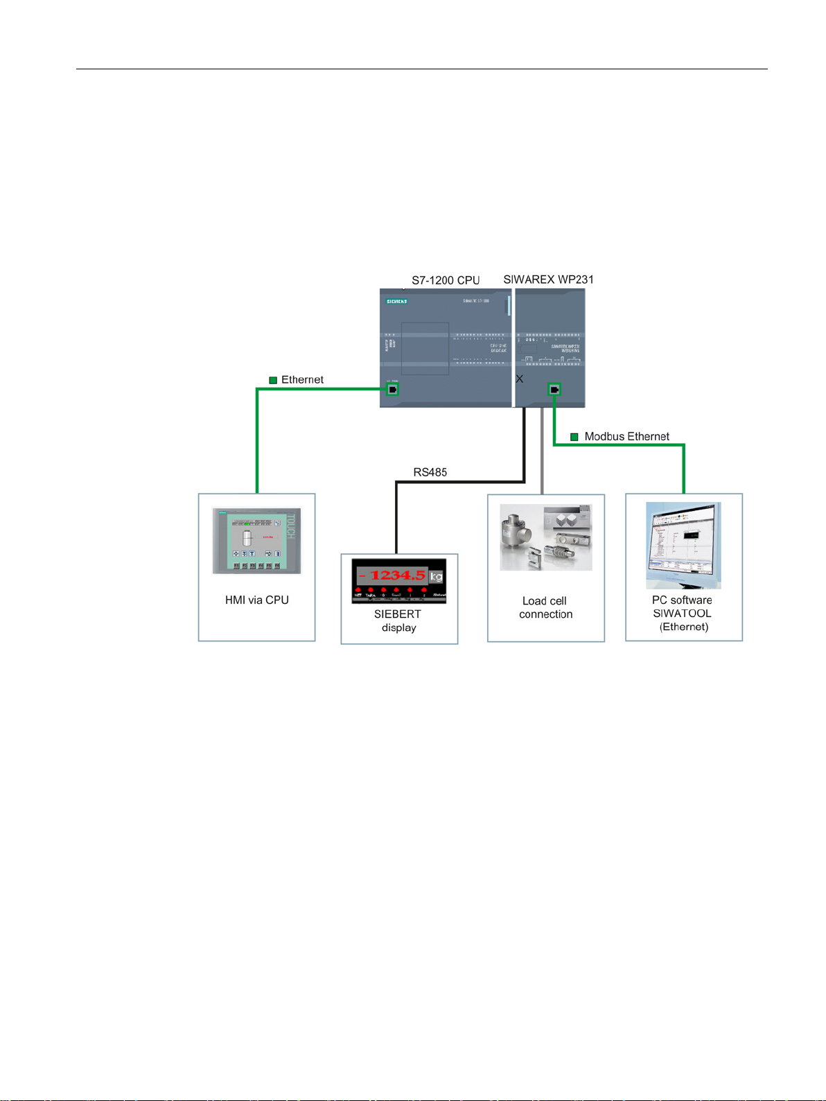
Figure 3-1 System overview
SIWAREX WP231
Manual, 07/2014, A5E31238908A-02
19

Description
3.6
Customer benefits
3.7
Scope of delivery
Note
3.6 Customer benefits
The electronic weighing system described here is characterized by decisive advantages:
● Uniform design technology and consistent communication in SIMATIC S7-1200
● Parameter assignment by means of HMI panel or PC
● Uniform configuration option in the SIMATIC TIA Portal
● Measuring of weight with a resolution of up to 4 million divisions
● High accuracy (3 000 d in accordance with OIML R-76)
● High measuring rate of 100/120 Hz (effective interference frequency suppression)
● Limit monitoring
● Flexible adaptation to varying requirements
● Easy adjustment of the scales using the SIWATOOL program
● Automatic calibration is possible without the need for calibration weights
● Module replacement is possible without recalibrating the scales
● Use in Ex Zone 2 / ATEX approval
● Intrinsically safe load cell supply for Ex Zone 1 (SIWAREX IS option)
● Diagnostics functions
The scope of delivery only includes the SIWAREX WP231 weighing module.
We recommend that you use the SIWAREX WP231 configuration package for configuring
the SIWAREX WP231 electronic weighing system. The configuration package is not included
in the scope of delivery of the module: → Accessories (Page 175).
SIWAREX WP231
20 Manual, 07/2014, A5E31238908A-02
4
4.1
Functions
P
The primary task of the electronic weighing system is the measurement and registration of
the current weight value. The integration in SIMATIC gives you the option to process the
weight value directly in the PLC (
The SIWAREX WP231 is calibrated at the factory. This allows for automatic calibration of the
scales without the need for calibration weights and replacement of modules without the need
for recalibrating the scales.
The Ethernet interface can be used to connect a PC for parameter assignment of the
electronic weighing system or for connection to any automation system (Modbus TCP/IP).
The SIWAREX WP231 electronic weighing system can also be used in potentially explosive
atmospheres (Zone 2). The load cells are supplied intrinsically safe in Zone 1 applications
when you use the optional Ex interface SIWAREX IS.
rogrammabelLogic Controller).
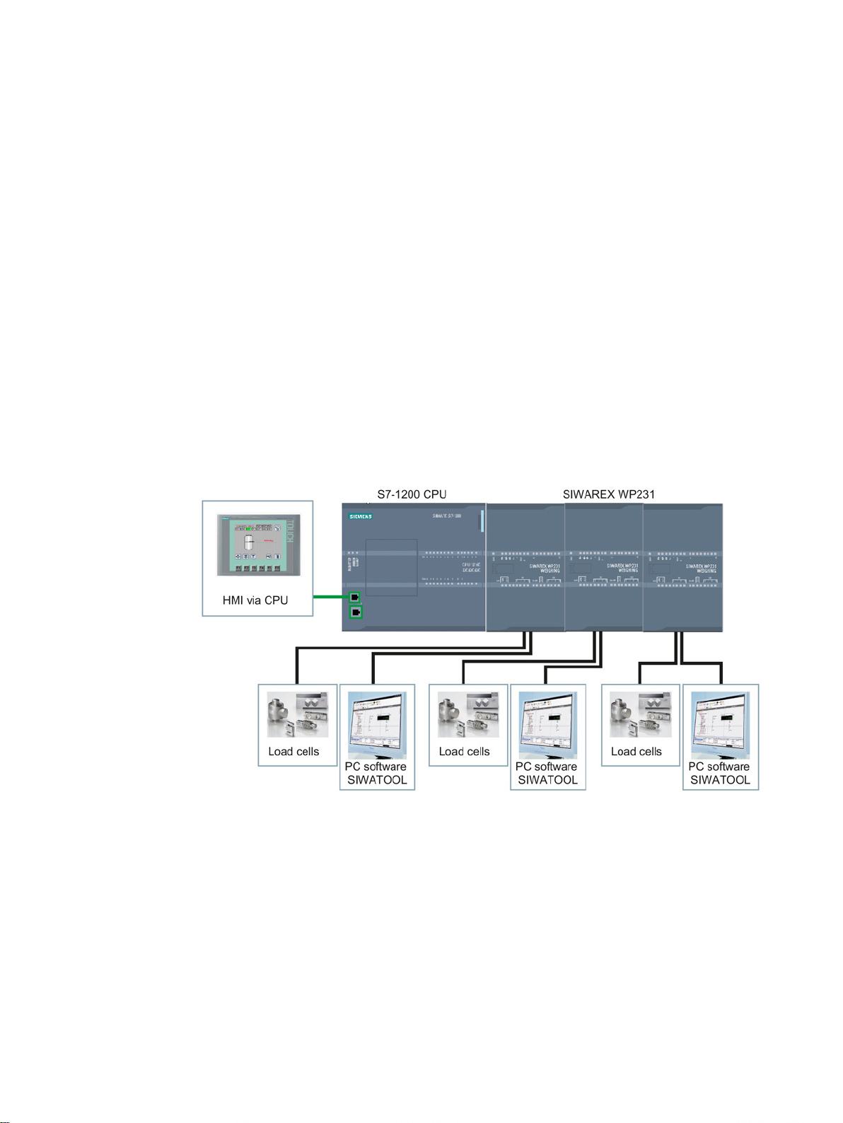
Figure 4-1 System integration in SIMATIC S7-1200
The SIWAREX WP231 can also be used in standalone mode independent of the automation
system. There are many configuration options in this case.
The user can select the enclosure as well as the Operator Panel. But the Operator Panel
must support Modbus RTU or TCP/IP. This means you can implement your own operating
philosophy.
The SIWAREX WP231 can be controlled remotely without its own Operator Panel on site.
One Operator Panel can be used for several scales. The configuration options are almost
unlimited in this case.
SIWAREX WP231
Manual, 07/2014, A5E31238908A-02
21
Application planning
4.2
Parameter assignment options
4.2.1
Parameter assignment with the PC
4.2 Parameter assignment options
You can set the scale parameters with the convenience of the familiar Windows interface by
using the "SIWATOOL" PC parameter assignment software.
You can use the program for commissioning the scale without any knowledge of automation
technology. When servicing is required, you can analyze and test the processes in the scale
independently of the automation system or Operator Panel with the help of the PC. You can
read out the diagnostic buffer from the SIWAREX module to assist you in the event analysis.
The figure below illustrates the structure of the individual program windows.
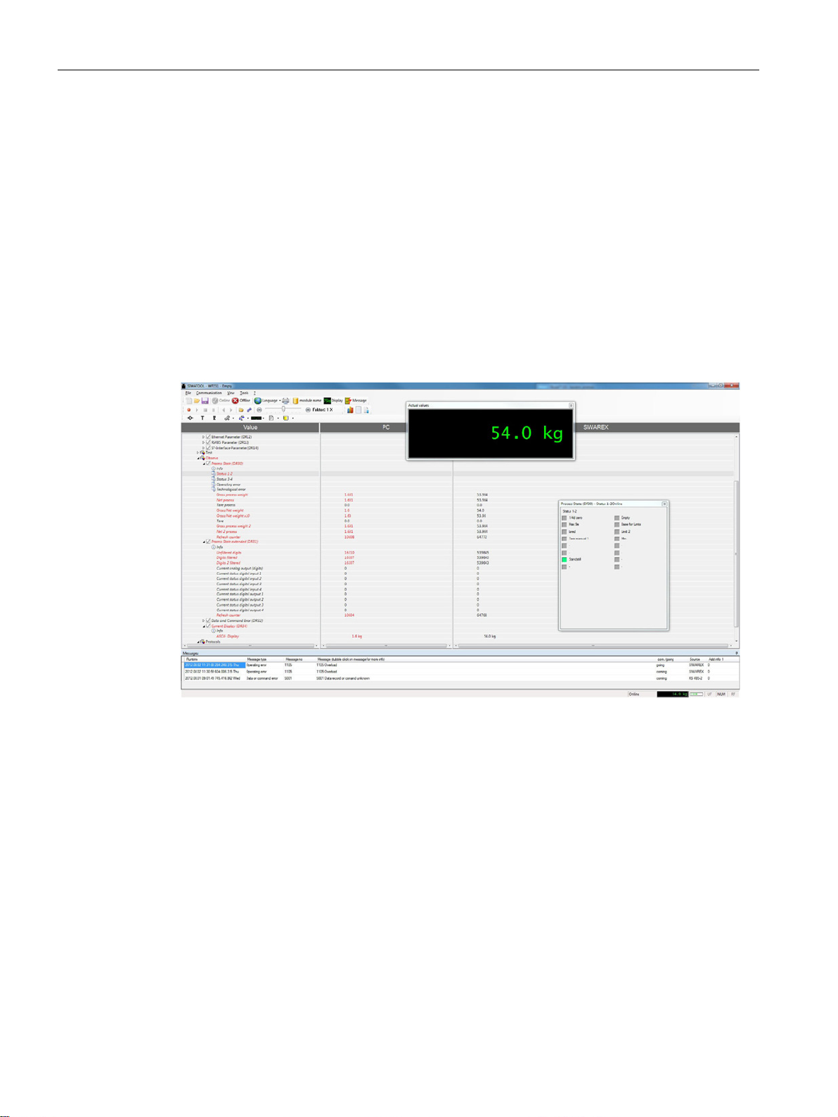
Figure 4-2 SIWATOOL overview
SIWATOOL does not only offer support when you set the scale but also when you analyze
the diagnostic buffer that can be saved after being read out of the module together with the
parameters. The display of the current scale status can be configured.
You can switch between several languages in the program.
SIWAREX WP231
22 Manual, 07/2014, A5E31238908A-02
Application planning
4.2.2
Parameter assignment with a SIMATIC Panel
4.2.3
Parameter assignment by means of the Modbus interface
4.2 Parameter assignment options
All parameters can be assigned and the module put into operation using a SIMATIC HMI
Panel connected to the S7-1200 CPU and the SIWAREX WP231 function and data blocks.
The Ready-for-Use software is included in the scope of delivery of the configuration
package. This includes the Step7 program for the CPU and the HMI project for scale
visualization. Further information on integration in the TIA Portal can be found in chapter
→ Integration in SIMATIC S7-1200 (Page 145).
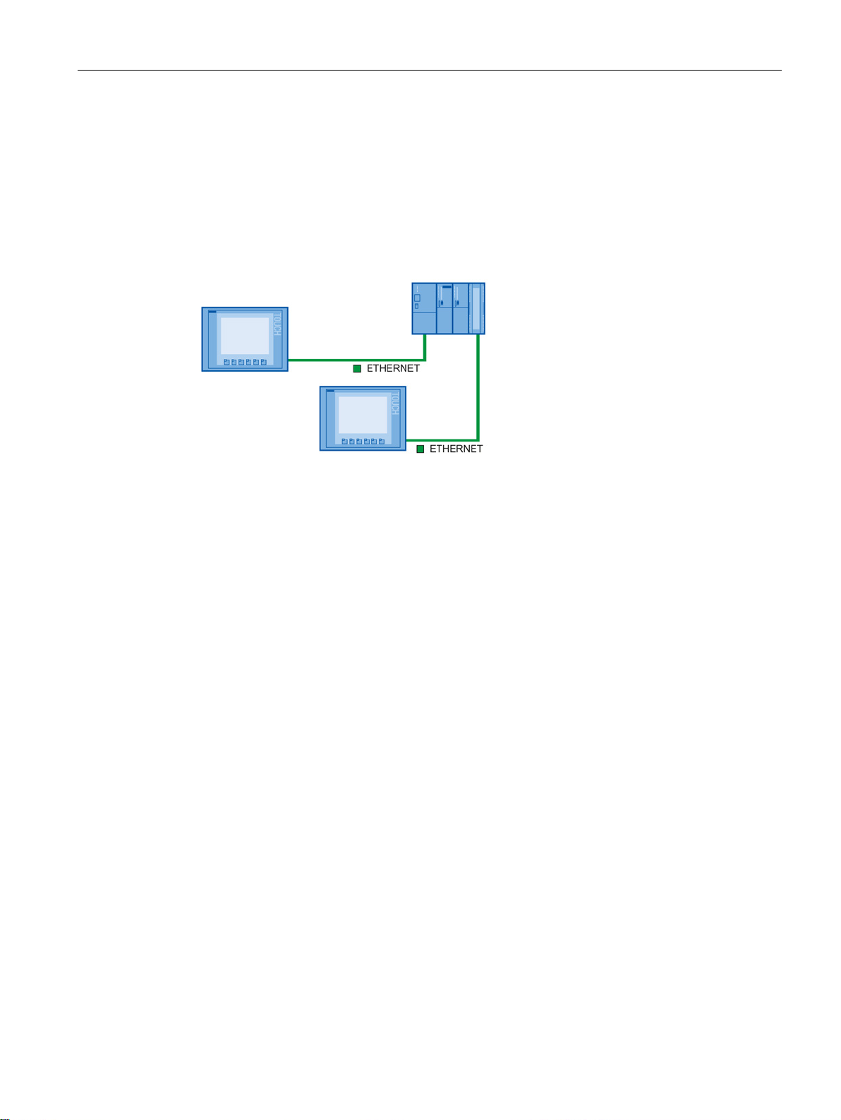
Figure 4-3 Configuration of the SIMATIC CPU with two Operator Panels
You have the option to assign the parameters with a SIMATIC panel which is connected
directly to the SIWAREX module. The SIWAREX module behaves like a Modbus slave in
this case. Loadable HMI software for a SIMATIC Panel TP700 Comfort is provided in the
scope of delivery of the configuration package.
All SIMATIC HMI Comfort Panels can be used for direct Modbus communication. The use of
SIMATIC HMI Basic Panels is not possible at the moment. A direct connection between a
SIMATIC HMI Panel and SIWAREX WP231 by means of Modbus RTU has not been
approved.
The parameters for the SIWAREX module can also be prepared in a third-party system and
transmitted to the electronic weighing system by means of Modbus RTU or TCP/IP. Detailed
information on assignment of the holding registers can be found in chapter → Scale
parameters and functions (Page 63).
SIWAREX WP231
Manual, 07/2014, A5E31238908A-02
23

Application planning
4.2 Parameter assignment options
SIWAREX WP231
24 Manual, 07/2014, A5E31238908A-02

5
5.1
Installation guideline
5.2
EMC-compliant setup
5.2.1
Introduction
EMC
5.2.2
Possible effects of interference
When installing the SIMATIC components together with the electronic weighing system
described here, the setup, installation and wiring guidelines for the SIMATIC S7-1200 must
be observed (see system manual "SIMATIC S7 S7-1200 automation system", order no.:
A5E02486681).
This manual describes additional installation and wiring aspects specific to the electronic
weighing system.
The electronic weighing system described here was developed for use in industrial
environments and complies with high EMC requirements. Nevertheless, you should still carry
out EMC planning before installing your devices in order to determine any sources of
interference and include them in your considerations.
EMC (electromagnetic compatibility) describes the capability of electrical equipment to
operate without errors in a given electromagnetic environment, without being subject to
external influence and without influencing external devices in any way.
Electromagnetic interferences can influence the electronic weighing system described here
in various ways:
● Electromagnetic fields having a direct influence on the system
● Interferences transported by communication cables
● Interferences having an effect via process cables
● Interferences entering the system via the power supply and/or protective ground
Interferences can impair the fault-free functioning of the electronic weighing system.
SIWAREX WP231
Manual, 07/2014, A5E31238908A-02
25

Mounting
5.2.3
Coupling mechanisms
5.2.4
Five basic rules for securing EMC
Rule 1: Large area grounding contact
Rule 2: Proper cable routing
Rule 3: Fixing the cable shielding
5.2 EMC-compliant setup
Depending on the propagation medium (conducted or non-conducted) and the distance
between the interference source and the device, interferences can enter the faulty device
through four different coupling mechanisms:
● Electrical coupling
● Capacitive coupling
● Inductive coupling
● Radiation coupling
Observe these five basic rules to secure EMC.
● When installing the devices, make sure that the surfaces of inactive metal parts are
properly bonded to chassis ground (see following sections).
● Bond all inactive metal parts to chassis ground, ensuring large area and low-impedance
contact (large cross-sections).
● When using screw connections on varnished or anodized metal parts, support contact
with special contact washers or remove the protective insulating finish on the points of
contact.
● Wherever possible, avoid the use of aluminum parts for ground bonding. Aluminum
oxidizes very easily and is therefore less suitable for ground bonding.
● Provide a central connection between chassis ground and the ground/protective
conductor system.
● Organize your wiring system into cable groups (high-voltage/power
supply/signal/measurement/data cables).
● Always route high-voltage and data cables in separate ducts or in separate bundles.
● Install the measurement cables as close as possible to grounded surfaces (e.g.
supporting beans, metal rails, steel cabinet walls).
● Ensure proper fixation of the cable shielding.
● Always use shielded data cables. Always connect both ends of the data cable shielding to
ground on a large area.
● Keep unshielded cable ends as short as possible.
● Always use metal/metalized connector housings only for shielded data cables.
SIWAREX WP231
26 Manual, 07/2014, A5E31238908A-02

Mounting
Rule 4: Special EMC measures
Rule 5: Homogeneous reference potential
5.2 EMC-compliant setup
● All inductors that are to be controlled should be connected with suppressors.
● For cabinet or enclosure lighting in the immediate range of your controller, use
incandescent lamps or interference suppressed fluorescent lamps.
● Create a homogeneous reference potential and ground all electrical equipment.
● Use sufficiently dimensioned equipotential bonding conductors if potential differences
exist or are expected between your system components. Equipotential bonding is
absolutely mandatory for applications in hazardous areas.
SIWAREX WP231
Manual, 07/2014, A5E31238908A-02
27

Mounting
5.3
Mounting on the SIMATIC S7-1200
5.3 Mounting on the SIMATIC S7-1200
The electronic weighing system described here is a SIMATIC S7-1200 module and can be
directly connected to the automation system's bus system. The 70 mm wide module has very
low installation and cabling requirements.
The module is fitted on a mounting rail, and the bus connection made using the slide switch.
The load cells, power supply and serial interfaces are connected via the screw-type
connectors.
Use of the WP231 in the SIMATIC TIA Portal is described in detail in cc 11 of this manual: →
Integration in SIMATIC S7-1200 (Page 145)
SIWAREX WP231
28 Manual, 07/2014, A5E31238908A-02
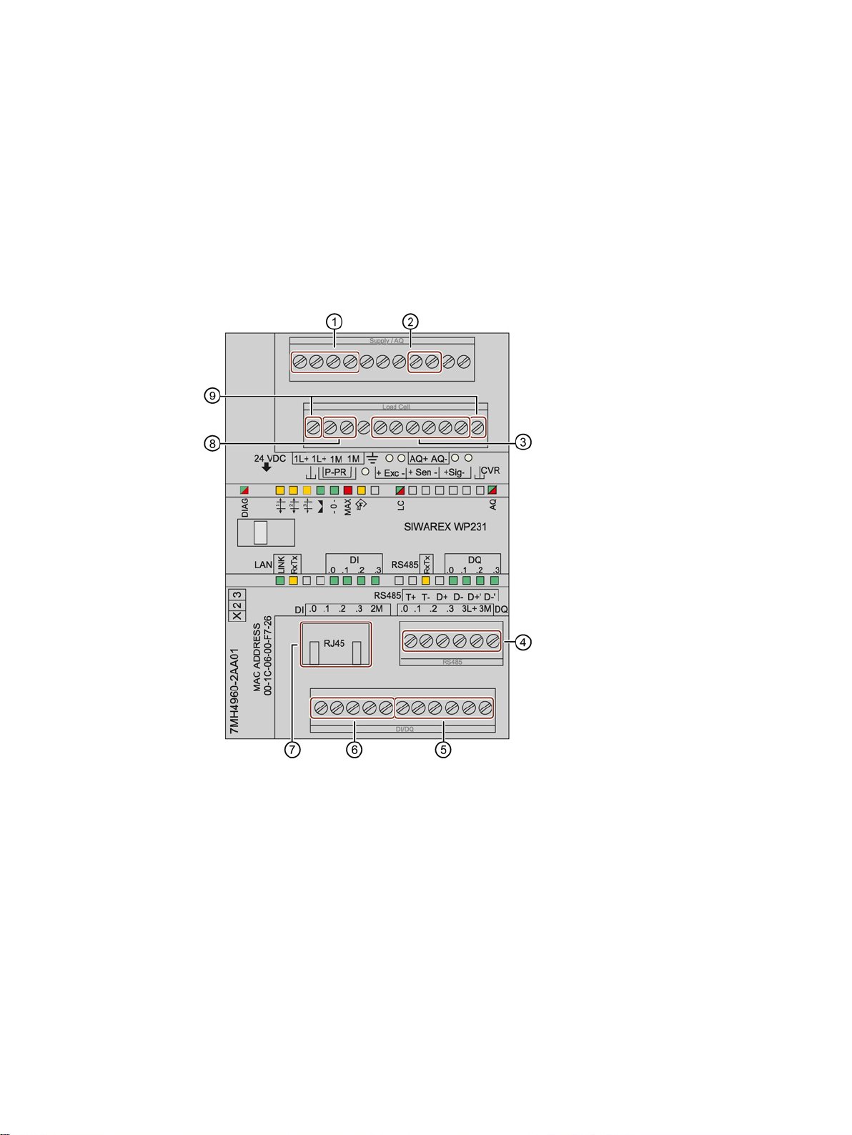
6
6.1
Overview
①
⑥
②
⑦
③
⑧
④
⑨
⑤
All external connections (with the exception of the Ethernet interface) are made by means of
the screw connectors (terminal block 1 to 4).
Figure 6-1 SIWAREX WP231 connection areas
SIWAREX WP231
Manual, 07/2014, A5E31238908A-02
24 V connection
Analog output connection
Load cell connection
RS485 interface connection
Digital output connection
Digital input connection
Ethernet interface connection
Calibration bridge connection
Mounting terminals for the calibration protec-
tion plate
29

Connection
6.2
24 V connection
Labeling
Function
6.3
Connecting the load cells
Overview
Rules
Observe the following rules when connecting analog (strain gauge) load cells:
6.2 24 V connection
The 24 V DC supply voltage is connected by means of the corresponding terminals on the
electronic weighing system.
Table 6- 1 Connection of the 24 V supply
L + +24 V voltage supply
M Ground voltage supply
Pickups can be connected to the SIWAREX WP231 electronic weighing system which are
equipped with strain gauges (DMS full bridge) and meet the following requirements.
● Characteristic value 1 to 4 mV/V
● A supply voltage of 5 V is permitted
The power supply for the load cells is 4.85 V.
The following condition must be satisfied in order to check the maximum possible number of
load cells which can be connected to a WP231:
● Scale operation without Ex interface: (input resistance of load cell) / (number of load cells)
> 40 Ohm
● Scale operation without Ex interface: (input resistance of load cell) / (number of load cells)
> 50 Ohm
1. The use of a junction box (SIWAREX JB junction box) is required when more than one
load cell is connected (the load cells must be connected in parallel). If the distance of a
load cell to the SIWAREX WP231 or the junction box is greater than the available length
of the load cell connection cable, use the SIWAREX EB extension box.
2. The cable shield is always applied at the cable gland of the junction box (SIWAREX JB)
or the extension box. If there is a risk of equipotential bonding through the cable shield,
connect a equipotential equalization conductor parallel to the load cell cable.
SIWAREX WP231
30 Manual, 07/2014, A5E31238908A-02
 Loading...