

Siemens SIWAREX WL280 Operating Instructions Manual

___________________
___________________
___________________
___________________
___________________
___________________
___________________
___________________
___________________
___________________
SIWAREX WL280
Compact installation units and guide elements RN-S SA
Operating Instructions
09/2016
A5E32605810A
Introduction
1
Notes on handling the
product
2
Description
3
Application planning
4
Mounting
5
Service and maintenance
6
Technical data
7
Dimension drawings
8
Ordering data
9
Appendix
A
-03
Siemens AG
Division Process Industries and Drives
Postfach 48 48
90026 NÜRNBERG
GERMANY
Document order number: A5E32605810
Ⓟ
Copyright © Siemens AG 2014 - 2016.
All rights reserved
Legal information
Warning notice system
DANGER
indicates that death or severe personal injury will result if proper precautions are not taken.
WARNING
indicates that death or severe personal injury may result if proper precautions are not taken.
CAUTION
indicates that minor personal injury can result if proper precautions are not taken.
NOTICE
indicates that property damage can result if proper precautions are not taken.
Qualified Personnel
personnel qualified
Proper use of Siemens products
WARNING
Siemens products may only be used for the applications described in the catalog and in the relevant technical
ambient conditions must be complied with. The information in the relevant documentation must be observed.
Trademarks
Disclaimer of Liability
This manual contains notices you have to observe in order to ensure your personal safety, as well as to prevent
damage to property. The notices referring to your personal safety are highlighted in the manual by a safety alert
symbol, notices referring only to property damage have no safety alert symbol. These notices shown below are
graded according to the degree of danger.
If more than one degree of danger is present, the warning notice representing the highest degree of danger will
be used. A notice warning of injury to persons with a safety alert symbol may also include a warning relating to
property damage.
The product/system described in this documentation may be operated only by
task in accordance with the relevant documentation, in particular its warning notices and safety instructions.
Qualified personnel are those who, based on their training and experience, are capable of identifying risks and
avoiding potential hazards when working with these products/systems.
Note the following:
documentation. If products and components from other manufacturers are used, these must be recommended
or approved by Siemens. Proper transport, storage, installation, assembly, commissioning, operation and
maintenance are required to ensure that the products operate safely and without any problems. The permissible
All names identified by ® are registered trademarks of Siemens AG. The remaining trademarks in this publication
may be trademarks whose use by third parties for their own purposes could violate the rights of the owner.
We have reviewed the contents of this publication to ensure consistency with the hardware and software
described. Since variance cannot be precluded entirely, we cannot guarantee full consistency. However, the
information in this publication is reviewed regularly and any necessary corrections are included in subsequent
editions.
for the specific
10/2016 Subject to change

Table of contents
1 Introduction ............................................................................................................................................. 5
2 Notes on handling the product ................................................................................................................. 9
3 Description ............................................................................................................................................ 11
4 Application planning .............................................................................................................................. 21
5 Mounting ............................................................................................................................................... 27
1.1 Purpose of this documentation ................................................................................................. 5
1.2 History ....................................................................................................................................... 5
1.3 Scope of delivery ...................................................................................................................... 5
1.3.1 Compact installation unit ........................................................................................................... 6
1.3.2 Guide element ........................................................................................................................... 6
1.4 Security information .................................................................................................................. 7
1.5 Environmental protection .......................................................................................................... 7
3.1 Application .............................................................................................................................. 11
3.1.1 Use of compact installation units ............................................................................................ 11
3.1.2 Lifting protection ...................................................................................................................... 12
3.1.3 Overload protection ................................................................................................................. 12
3.1.4 Use of the grounding cable ..................................................................................................... 13
3.1.5 Application of guide elements ................................................................................................. 13
3.2 Design and function ................................................................................................................ 14
3.2.1 Design and mode of operation of the compact installation unit .............................................. 14
3.2.2 Design and function of the grounding cable ........................................................................... 18
3.2.3 Design and principle of operation of the guide element ......................................................... 19
4.1 Load cell dummies .................................................................................................................. 21
4.2 Lifting protection ...................................................................................................................... 21
4.3 Load pick-up ........................................................................................................................... 22
4.4 Overload protection ................................................................................................................. 23
4.5 Guide elements ....................................................................................................................... 25
4.6 Protection against explosion ................................................................................................... 26
5.1 Safety information/instructions ................................................................................................ 27
5.2 Installing the compact installation unit .................................................................................... 28
5.2.1 General installation information .............................................................................................. 28
5.2.2 Preparing the load cell ............................................................................................................ 29
5.2.3 Preparing the compact installation unit ................................................................................... 30
5.2.4 Installing the load cell in the compact installation unit ............................................................ 31
5.2.5 Installing the compact installation unit .................................................................................... 33
5.2.6 Lowering the top plate onto the load cells .............................................................................. 36
5.2.7 Compensation of height with four or more support points ...................................................... 37
RN-S SA
Operating Instructions, 09/2016, A5E32605810A-03
3

Table of contents
6 Service and maintenance ...................................................................................................................... 45
7 Technical data ...................................................................................................................................... 47
8 Dimension drawings .............................................................................................................................. 49
9 Ordering data ........................................................................................................................................ 53
A Appendix .............................................................................................................................................. 55
Index .................................................................................................................................................... 57
5.2.8 Checking the installation ........................................................................................................ 38
5.3 Fixing of guide element .......................................................................................................... 39
5.3.1 General installation information ............................................................................................. 39
5.3.2 Preparing the guide element .................................................................................................. 40
5.3.3 Locking the top plate .............................................................................................................. 40
5.3.4 Fixing a guide element (or the first one) ................................................................................ 41
5.3.5 Lowering the top plate onto the load cells ............................................................................. 41
5.3.6 Fixing of second guide element ............................................................................................. 42
5.3.7 Checking the installation ........................................................................................................ 42
5.4 Dismantling ............................................................................................................................ 43
6.1 Servicing and maintenance .................................................................................................... 45
7.1 Stainless steel compact installation units .............................................................................. 47
7.2 Stainless steel guide elements .............................................................................................. 47
8.1 Dimension drawings of the compact installation units ........................................................... 49
8.2 Dimension drawing of guide elements ................................................................................... 52
A.1 Technical support ................................................................................................................... 55
RN-S SA
4 Operating Instructions, 09/2016, A5E32605810A-03

1
1.1
Purpose of this documentation
1.2
History
Edition
Comment / change
05/2015
Corrections in measurement tables
09/2016
Corrections in measurement tables
1.3
Scope of delivery
These instructions contain all the information you need for commissioning and using the
device.
It is aimed at persons who install the device mechanically and commission it, as well as at
service and maintenance engineers.
The following versions of this documentation have been released to date. The changes apply
to the previous version:
Table 1- 1 History
09/2014 Initial release
The scope of delivery is made up of the following components:
RN-S SA
Operating Instructions, 09/2016, A5E32605810A-03
5

Introduction
1.3.1
Compact installation unit
Note
Other scope of delivery information
Drawings of the parts of the compact installation unit can be found in Section
compact installation unit
1.3.2
Guide element
1.4 Security information
Compact installation unit
Accessory kit 1
● 1 x pressure piece complete with flat seal
● 1 x pendulum support
Accessory kit 2
● 8 x washers
Preparing the
(Page 30)
2 x flanges
1 x turnbuckle complete
Accessory kit for
RN-S SA 60 kg to 280 kg
RN-S SA 0.5 t / 1 t
RN-S SA 2 t to 5 t
● 2 x hexagon bolts
● 2 x hexagon nuts
● 4 x washers
● 4 x cylinder head screws
Accessory kit for
RN-S SA 10 t / 13 t
● 2 x hexagon bolts
● 2 x hexagon nuts
● 4 x washers
● 6 x cylinder head screws
RN-S SA
6 Operating Instructions, 09/2016, A5E32605810A-03

Introduction
1.4
Security information
1.5
Environmental protection
Recycling
1.4 Security information
Siemens provides products and solutions with industrial security functions that support the
secure operation of plants, systems, machines and networks.
In order to protect plants, systems, machines and networks against cyber threats, it is
necessary to implement – and continuously maintain – a holistic, state-of-the-art industrial
security concept. Siemens’ products and solutions only form one element of such a concept.
Customer is responsible to prevent unauthorized access to its plants, systems, machines
and networks. Systems, machines and components should only be connected to the
enterprise network or the internet if and to the extent necessary and with appropriate security
measures (e.g. use of firewalls and network segmentation) in place.
Additionally, Siemens’ guidance on appropriate security measures should be taken into
account. For more information about industrial security, please visit:
http://www.siemens.com/industrialsecurity
Siemens’ products and solutions undergo continuous development to make them more
secure. Siemens strongly recommends to apply product updates as soon as available and to
always use the latest product versions. Use of product versions that are no longer supported,
and failure to apply latest updates may increase customer’s exposure to cyber threats.
To stay informed about product updates, subscribe to the Siemens Industrial Security RSS
Feed under:
http://www.siemens.com/industrialsecurity
Devices described in this programming manual can be recycled owing to the low content of
noxious substances in their version.
Please contact a certified waste disposal company for eco-friendly recycling and to dispose
of your old devices.
RN-S SA
Operating Instructions, 09/2016, A5E32605810A-03
7

Introduction
1.5 Environmental protection
RN-S SA
8 Operating Instructions, 09/2016, A5E32605810A-03

2
Proper use
Notes on liability for defects
Delivery information
Qualified personnel
Proper use means that this product must only be used within the limits of the technical
specifications and intended purposes of these operating instructions.
If this device is used properly in compliance with the safety notices, this device will not
present any danger.
This device can only function correctly and safely if it is transported, stored, set up and
mounted correctly.
Correct operation of the device must be ensured by complying with the technical
specifications.
Improper handling can result in death, personal injury or property damage.
We expressly point out that the product quality is exclusively and conclusively described in
the sales contract. The content of this product documentation is neither part of a previous or
existing agreement, promise or legal relationship, nor is it intended to modify these. All
obligations on the part of Siemens AG are contained in the respective sales contract, which
also contains the complete and solely applicable liability provisions. The provisions defined
in the sales contract for the responsibility for defects are neither extended nor limited by the
remarks in this document.
The current scope of delivery is listed on the shipping documents enclosed with the delivery
in accordance with the valid sales contract.
When opening the packaging, please observe the relevant information. Check the delivery
for completeness and undamaged condition. In particular, the order number on the rating
plate must be compared to the ordering data.
Before you start work, please read these operating instructions. They contain important
information and data whose observation ensures the general safety and functionality of this
device. The manual will help you to handle this product more easily and efficiently, allowing
you to achieve reliable results.
In the context of this documentation, qualified personnel are people who are familiar with the
installation, mounting, commissioning, and operation of the product.
RN-S SA
Operating Instructions, 09/2016, A5E32605810A-03
9

Notes on handling the product
Protection against explosion
Trademarks
These people must have the following qualifications:
● They must be trained, instructed and authorized to operate and maintain devices and
systems in accordance with their place of work and in compliance with the safety
engineering standards for
– Electrical circuits
– High pressures
– Corrosive and hazardous media
● They must be trained, instructed and authorized to maintain and use appropriate safety
equipment according to the standards for safety engineering.
● In the case of devices with explosion protection, qualified persons must be trained,
instructed and authorized to perform work on electrical circuits in plants subject to
explosion hazards.
There is no potential risk of ignition from the installation units of the load cells. Therefore they
are not subject to the EC directive 94/9 EC (ATEX).
SIWAREX ® is a registered trademark of Siemens AG.
All other names appearing in these instructions may be trademarks; use of such names by
third parties for their own purposes may infringe upon owners rights.
RN-S SA
10 Operating Instructions, 09/2016, A5E32605810A-03

3
3.1
Application
3.1.1
Use of compact installation units
The compact installation unit handles the introduction of force into the load cells by means of
a pendulum support.
This pendulum support has the following effect:
● The weight force is introduced centrally into the load cell.
● The load cell is decoupled from the load bearing implement, e.g. of a container. The load
bearing implement can expand, e.g. as a result of changes in temperature, without
tensioning the load cell.
● The load bearing implement remains in the center in the event of thermal expansion.
● Following a lateral displacement, the load bearing implement returns to its rest position as
soon as the transverse force is no longer active.
The compact installation unit allows simple and exact installation of the load cell:
● It is not necessary to strip down the compact installation unit.
● It is not necessary to remove the compact installation unit.
● The compact installation unit can be used as dummy.
● The top plate is secured by means of two countersunk head screws.
● As a result of the two countersunk head screws, the position of the top plate with regard
to the base plate is adjusted ideally.
● The load cell can be inserted before or after installation of the compact installation unit.
● The load cell is protected during installation work.
● The load bearing implement can be lowered safely and controlled onto the load cell.
The compact installation units have the following characteristics:
● Easy installation of the load cell
● Easy adjustment of the load cell under the load bearing implement
● Self-centering on the load bearing implement
● Can be used as a dummy for light installation work
● Safe and controlled lowering of the load bearing implement
● Can be used as a transport lock by fixing the top plate
● Integrated lifting protection
RN-S SA
Operating Instructions, 09/2016, A5E32605810A-03
11
Description
Compact installation unit for SIWAREX WL280 RN-S SA
3.1.2
Lifting protection
3.1.3
Overload protection
3.1 Application
● Designed relief of the load cell during installation
● Overload protection of the load cell during installation
● Prepared for the attachment of guide elements: single-sided or double-sided
● Compensation of tolerance of connection holes through mounting with spring washers
● Checking of correct installation using conical washer
● Highly flexible ground wire for protection of load cell against parasitic currents
● Parts made of stainless steel for applications in the food and pharmaceutical industries
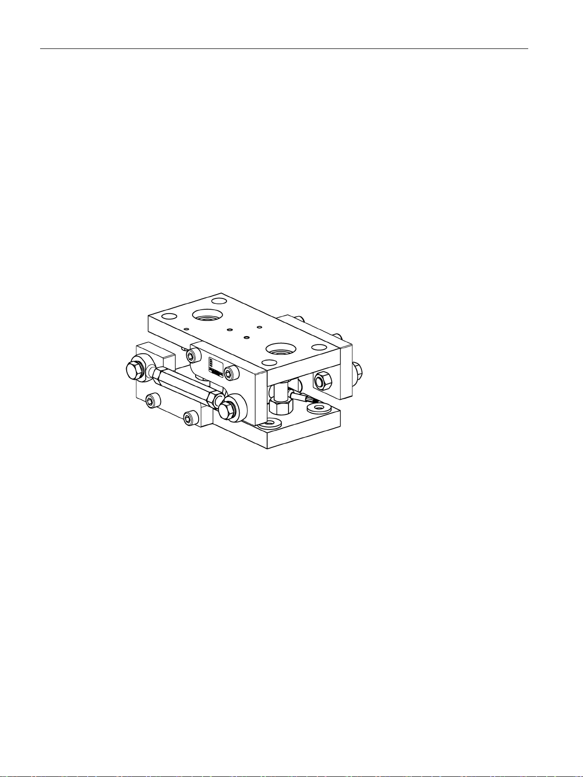
The type SIWAREX WL280 RN-S SA self-centering compact installation unit for load cells is
especially well suited for installation in container scales, platform scales and roller table
scales.
RN-S SA
12 Operating Instructions, 09/2016, A5E32605810A-03
The lifting protection prevents the load bearing implements from being lifted off the load
cells.
If there is a risk of the load bearing implement being lifted or toppled, then lifting protection is
required. This is required in the case of lightweight containers and tall, outdoor silos.
The overload protection protects load cells from a load that is too great.
There is overload protection against excessive loads in the measuring direction and overload
protection against excessive transverse forces.
Transverse forces are caused by, for example, wind, filling processes, acceleration, or
conveyor belt friction. If these forces exceed certain values, the load cells must be protected
from them.
Description
3.1.4
Use of the grounding cable
3.1.5
Application of guide elements
3.1 Application
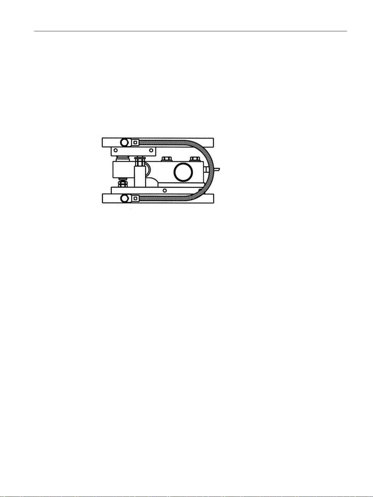
The grounding cable is used to protect the load cells from undesired currents. The causes of
such currents are, for example:
● Equalizing currents with missing or faulty equipotential bonding conductors
● A lightning strike nearby
● Welding work
● Static charge
Figure 3-1 Example usage of the grounding cable
Guide elements route horizontal forces acting on load bearing implements directly into the
foundation. Transverse forces onto the load cells do not occur as a result. The result of the
load cells is not falsified by this influence.
Guide elements are used in the following cases:
● Horizontal forces occur during the weighing procedure. This is the case with all dynamic
weighing procedures or if containers are weighed outdoors where wind can have an
effect.
● Movement of the load bearing implement as a result of horizontal forces should be
prevented. This is the case with braking or acceleration forces of belt or roller table scales
or with mixing tanks in which unbalance can occur as a result of an agitator.
The SIWAREX WL280 RN-S SA guide elements are used together with the compact
installation units. The guide elements have the following characteristics:
● Subsequent attachment to the compact installation unit
● The single-sided attachment of a guide element can be made either on the front or rear of
the compact installation unit.
● The double-sided attachment of two guide elements doubles the possible transverse
force.
● Parts made of stainless steel for applications in the food and pharmaceutical industries
The weighing equipment must not be tensioned by guide elements. The guide elements
must not prevent changes in the dimensions of the load bearing implement resulting from
RN-S SA
Operating Instructions, 09/2016, A5E32605810A-03
13

Description
3.2
Design and function
3.2.1
Design and mode of operation of the compact installation unit
Design
3.2 Design and function
changes in temperature. This can principally be achieved by always using three guide
elements.
The compact installation unit comprises the following main components:
● Base plate
● Top plate
● Pendulum support
● Two countersunk head screws
Together with the load cell, the compact installation unit represents a self-centering bearing
unit.
①
②
④
⑩ as aids to installation and adjustment
RN-S SA
14 Operating Instructions, 09/2016, A5E32605810A-03
Description
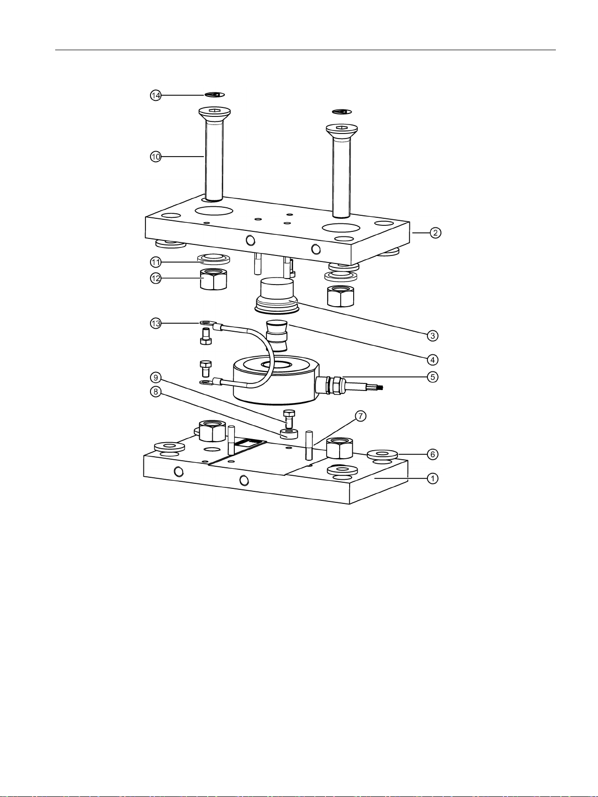
①
Base plate
⑧
Clamping washers
②
Top plate
⑨
Hexagon-head bolts
③
Pressure piece with flat seal
⑩
Countersunk head screws
④
Pendulum support
⑪
Centering washers
⑤
ery)
⑫
⑥
Spring washers
⑬
Grounding cable
⑦
Half length taper-grooved pins
⑭
Plug
Principle of operation
3.2 Design and function
RN-S SA
Operating Instructions, 09/2016, A5E32605810A-03
Load cell (not included in scope of deliv-
Figure 3-2 Exploded view: compact installation unit with built-in load cell
The top plate is exactly aligned and secured through the base plate using the two
countersunk head screws. This results in a stable unit.
Hexagon nut
15
Description
s
Excess length = lifting path
3.2 Design and function
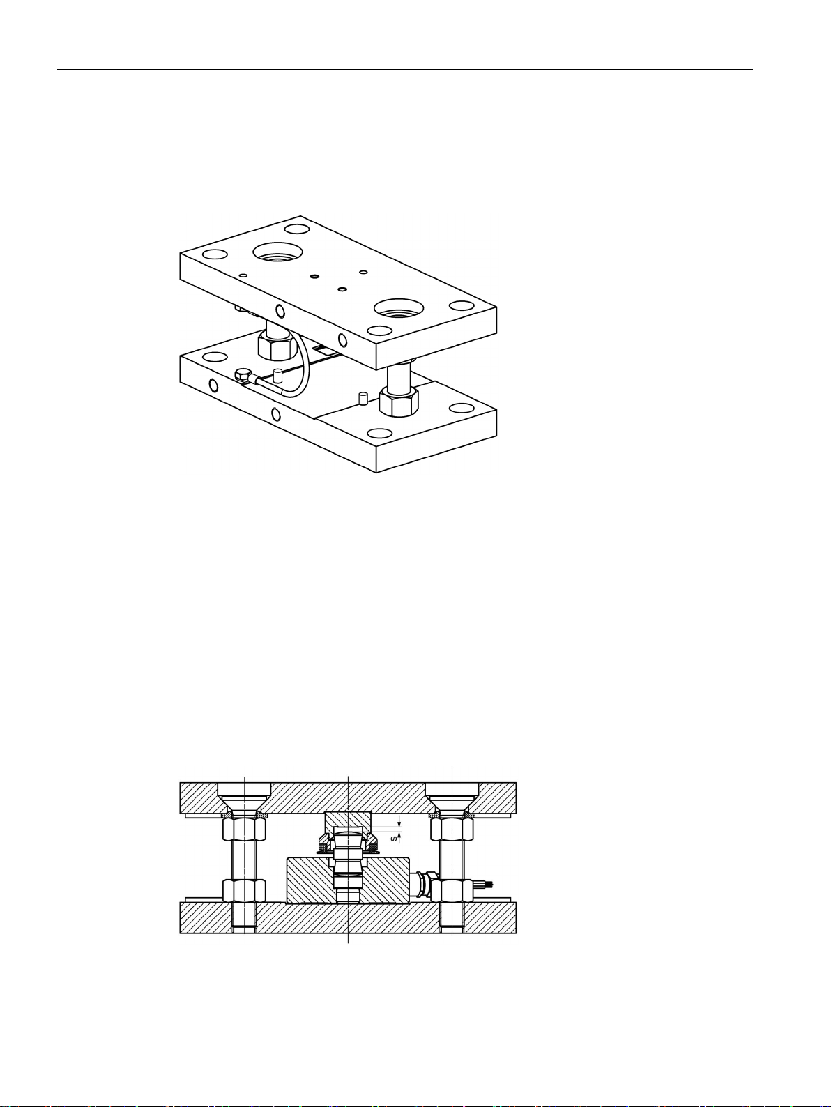
When delivered, the height of the top plate is set with an excess length. The excess length
corresponds to the lifting path (see Stainless steel compact installation units (Page 47)).
In this condition, the compact installation unit serves as an installation aid and can be used
as a dummy for lighter installation work.
Figure 3-3 Compact installation unit: pre-assembled upon delivery
Prior to installation, the load cell with pendulum support and pressure piece is inserted into
the compact installation unit. The load cell and pressure piece are secured in position using
one clamping washer each.
In the next step, the complete compact installation units are fitted into the scale.
The fixing holes of the compact installation unit are 6 mm larger than the thread of the fixing
screws to be used. The fixing holes are covered by the supplied spring washers. Tolerance
errors in the fixing holes of the brackets can then be compensated to a certain extent.
Compensate angular and/or flatness errors as well as differences in height between the
brackets using spacer plates. Make sure that the connection plates are not tensioned and
that the base/top plates are not concave in the center.
The compact installation units are optimally aligned when screwed tight. The load cells are
not yet loaded.
RN-S SA
16 Operating Instructions, 09/2016, A5E32605810A-03
Figure 3-4 Installation state
Description
NOTICE
Loosening the hexagon nuts
3.2 Design and function
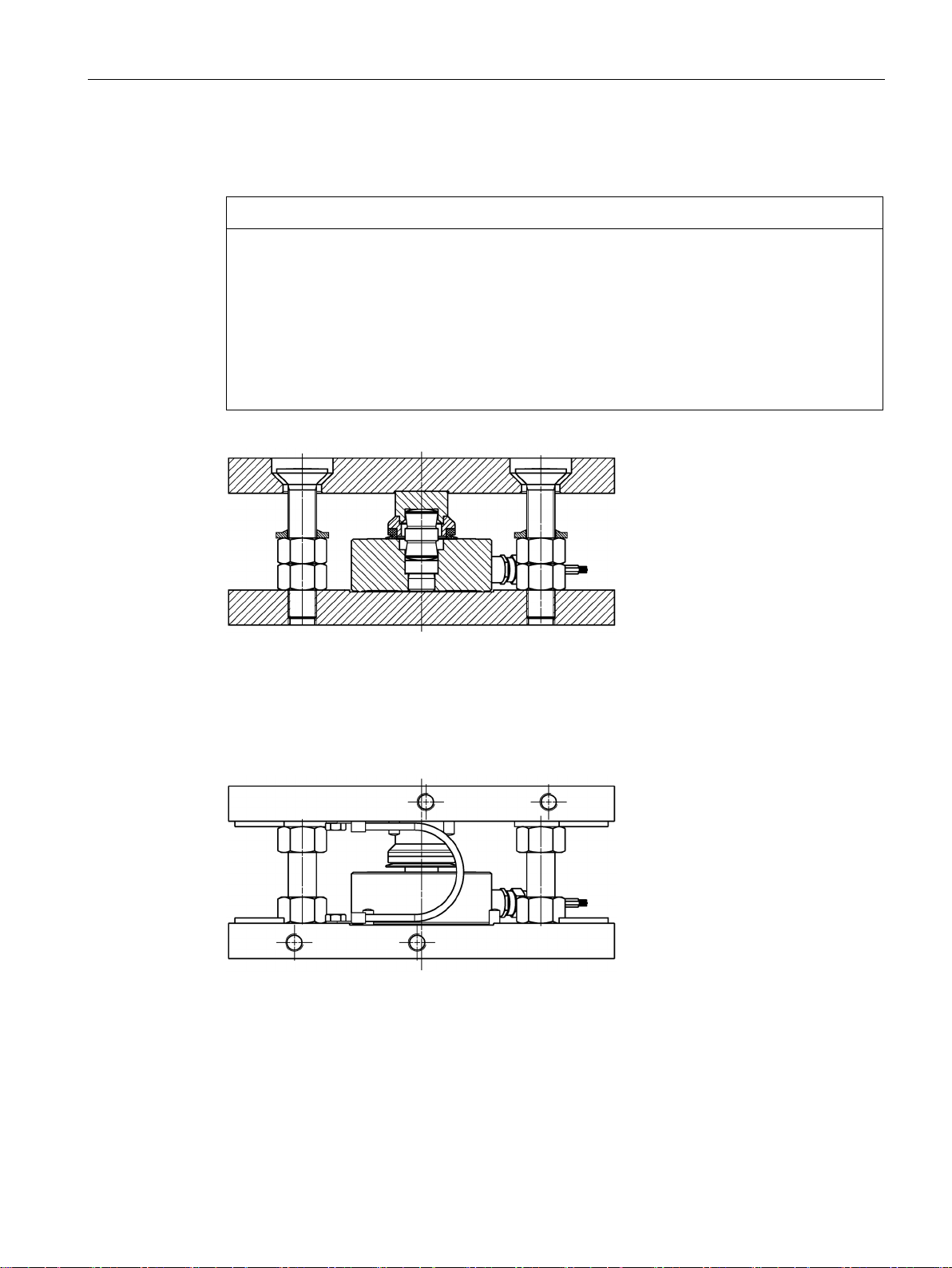
In the next step, lower the load bearing by loosening the top hexagon nuts. The top plate is
lowered onto the pendulum support. The weight is now on the load cells.
Loosen the hexagon nuts in turn in small steps.
Note:
• The compact installation units are screwed tight to the brackets.
• By loosening a hexagon nut, the weight of the bearing implement is distributed among
the other hexagon nuts and is partially increased.
Avoid overloading individual hexagon nuts.
Figure 3-5 Operating state
In this state, the load cells with the pressure pieces form self-centering units. The compact
installation units allow the top plates and the load bearing implement to be deflected to the
side. The countersunk head screws provide lifting protection and, to a limited extent,
pendulum limitation.
Figure 3-6 Compact installation unit with load cell and grounding cable
RN-S SA
Operating Instructions, 09/2016, A5E32605810A-03
17

Description
3.2.2
Design and function of the grounding cable
Structure
Principle of operation
3.2 Design and function
The grounding cables in the compact installation units are made up of fine-core flexible
copper wires. The flexible copper wires are tin-coated to additionally protect the copper from
corrosion.
The grounding cable represents an electrical by-pass via the load cell. High weld currents
can destroy the load cell, installation unit or the electronics. The electronics can be affected
by voltage sparkovers of static discharges.
RN-S SA
18 Operating Instructions, 09/2016, A5E32605810A-03
 Loading...