

Siemens SIWAREX WL270 CP-S SB Operating Instructions Manual

CP-S SB
_
_
_
_
_
_
_
_
_
_
_
_
_
_
_
_
_
_
_
_
SIWAREX WL270
Pressure piece set
CP-S SB
Operating Instructions
_________________
Introduction
Notes on handling the
_________________
product
_________________
Description
_________________
Application planning
_________________
Installation
_________________
Service and maintenance
_________________
Technical data
_________________
Dimension drawings
_________________
Ordering data
_________________
Appendix
1
2
3
4
5
6
7
8
9
A
11/2010
A5E03323543B
Legal information
Legal information
Warning notice system
This manual contains notices you have to observe in order to ensure your personal safety, as well as to prevent
damage to property. The notices referring to your personal safety are highlighted in the manual by a safety alert
symbol, notices referring only to property damage have no safety alert symbol. These notices shown below are
graded according to the degree of danger.
DANGER
indicates that death or severe personal injury will result if proper precautions are not taken.
WARNING
indicates that death or severe personal injury may result if proper precautions are not taken.
CAUTION
with a safety alert symbol, indicates that minor personal injury can result if proper precautions are not taken.
CAUTION
without a safety alert symbol, indicates that property damage can result if proper precautions are not taken.
NOTICE
indicates that an unintended result or situation can occur if the corresponding information is not taken into
account.
If more than one degree of danger is present, the warning notice representing the highest degree of danger will
be used. A notice warning of injury to persons with a safety alert symbol may also include a warning relating to
property damage.
Qualified Personnel
The product/system described in this documentation may be operated only by personnel qualified for the specific
task in accordance with the relevant documentation for the specific task, in particular its warning notices and
safety instructions. Qualified personnel are those who, based on their training and experience, are capable of
identifying risks and avoiding potential hazards when working with these products/systems.
Proper use of Siemens products
Note the following:
WARNING
Siemens products may only be used for the applications described in the catalog and in the relevant technical
documentation. If products and components from other manufacturers are used, these must be recommended
or approved by Siemens. Proper transport, storage, installation, assembly, commissioning, operation and
maintenance are required to ensure that the products operate safely and without any problems. The permissible
ambient conditions must be adhered to. The information in the relevant documentation must be observed.
Trademarks
All names identified by ® are registered trademarks of the Siemens AG. The remaining trademarks in this
publication may be trademarks whose use by third parties for their own purposes could violate the rights of the
owner.
Disclaimer of Liability
We have reviewed the contents of this publication to ensure consistency with the hardware and software
described. Since variance cannot be precluded entirely, we cannot guarantee full consistency. However, the
information in this publication is reviewed regularly and any necessary corrections are included in subsequent
editions.
Siemens AG
Industry Sector
Postfach 48 48
90026 NÜRNBERG
GERMANY
A5E03323543B
Ⓟ 05/2011
Copyright © Siemens AG 2010.
Technical data subject to change

Table of contents
1 Introduction................................................................................................................................................ 5
1.1
1.2
1.3
1.4
2
Notes on handling the product................................................................................................................... 7
3
Description................................................................................................................................................. 9
3.1
3.1.1
3.1.2
3.1.3
3.1.4
3.2
3.2.1
3.2.2
Application planning................................................................................................................................. 15
4
4.1
4.2
4.3
4.4
Purpose of this documentation ......................................................................................................5
History............................................................................................................................................5
Scope of delivery ...........................................................................................................................5
Environmental protection ...............................................................................................................5
Application......................................................................................................................................9
Use of the pressure piece set ........................................................................................................9
Lifting protection...........................................................................................................................10
Overload protection......................................................................................................................10
Use of the grounding cable..........................................................................................................11
Layout and function......................................................................................................................11
Design and function of the pressure piece set.............................................................................11
Design and function of the grounding cable ................................................................................13
Load cell dummies .......................................................................................................................15
Lifting protection...........................................................................................................................15
Load pick-up.................................................................................................................................16
Overload protection......................................................................................................................17
4.5
4.6
5
Installation ............................................................................................................................................... 21
5.1
5.2
5.2.1
5.2.2
5.2.3
5.2.4
5.2.5
5.2.6
5.3
5.4
6
Service and maintenance ........................................................................................................................ 29
6.1
CP-S SB
Operating Instructions, 11/2010, A5E03323543B
Guide elements............................................................................................................................19
Protection against explosion ........................................................................................................20
Safety information/instructions.....................................................................................................21
Mounting the pressure piece set..................................................................................................23
General installation information ...................................................................................................23
Overview ......................................................................................................................................23
Preparing the load cell .................................................................................................................24
Preparing the pressure piece set.................................................................................................25
Installing the load cell with pressure piece set.............................................................................25
Checking the installation ..............................................................................................................27
Installing the grounding cable ......................................................................................................27
Dismantling ..................................................................................................................................28
Servicing and maintenance..........................................................................................................29
3

Table of contents
7 Technical data ......................................................................................................................................... 31
7.1 Technical data............................................................................................................................. 31
8
Dimension drawings ................................................................................................................................ 33
8.1
8.2
9
Ordering data........................................................................................................................................... 35
9.1
A
Appendix.................................................................................................................................................. 37
A.1
Index........................................................................................................................................................ 39
Dimension drawing of the pressure piece set............................................................................. 33
Dimension drawing of the grounding cable................................................................................. 33
Ordering data .............................................................................................................................. 35
Technical support........................................................................................................................ 37
CP-S SB
4 Operating Instructions, 11/2010, A5E03323543B

Introduction
1.1 Purpose of this documentation
These instructions contain all the information you need for commissioning and using the
device.
It is aimed at persons who install the device mechanically and commission it, as well as at
service and maintenance engineers.
1.2 History
The following versions of this documentation have been released to date. The changes apply
to the previous version:
Edition Comment / change
10/2010 Initial release
1
1.3 Scope of delivery
The scope of delivery is made up of the following components:
● Information sheet
● Pressure piece set
Note
Other scope of delivery information
Drawings of the parts of the pressure piece set can be found in Section Preparing the
pr
essure piece set (Page 25)
1.4 Environmental protection
Recycling
Devices described in this programming manual can be recycled owing to the low content of
noxious substances in their version.
Please contact a certified waste disposal company for eco-friendly recycling and to dispose
of your old devices.
CP-S SB
Operating Instructions, 11/2010, A5E03323543B
5

Introduction
1.4 Environmental protection
CP-S SB
6 Operating Instructions, 11/2010, A5E03323543B

Notes on handling the product
Proper use
Proper use means that this product must only be used within the limits of the technical
specifications and intended purposes of these operating instructions.
If this device is used properly in compliance with the safety notices, this device will not
present any danger.
This device can only function correctly and safely if it is transported, stored, set up and
mounted correctly.
Correct operation of the device must be ensured by complying with the technical
specifications.
Improper handling can result in death, personal injury or property damage.
Notes on liability for defects
We expressly point out that the product quality is exclusively and conclusively described in
the sales contract. The content of this product documentation is neither part of a previous or
existing agreement, promise or legal relationship, nor is it intended to modify these. All
obligations on the part of Siemens AG are contained in the respective sales contract, which
also contains the complete and solely applicable liability provisions. The provisions defined
in the sales contract for the responsibility for defects are neither extended nor limited by the
remarks in this document.
2
Delivery information
The current scope of delivery is listed on the shipping documents enclosed with the delivery
in accordance with the valid sales contract.
When opening the packaging, please observe the relevant information. Check the delivery
for completeness and undamaged condition. In particular, the order number on the rating
plate must be compared to the ordering data.
Before you start work, please read these operating instructions. They contain important
information and data whose observation ensures the general safety and functionality of this
device. The manual will help you to handle this product more easily and efficiently, allowing
you to achieve reliable results.
CP-S SB
Operating Instructions, 11/2010, A5E03323543B
7

Notes on handling the product
Qualified personnel
In the context of this documentation, qualified personnel are people who are familiar with the
installation, mounting, commissioning, and operation of the product.
These people must have the following qualifications:
● They must be trained, instructed and authorized to operate and maintain devices and
systems in accordance with their place of work and in compliance with the safety
engineering standards for
– Electrical circuits
– High pressures
– Corrosive and hazardous media
● They must be trained, instructed and authorized to maintain and use appropriate safety
equipment according to the standards for safety engineering.
● In the case of devices with explosion protection, qualified persons must be trained,
instructed and authorized to perform work on electrical circuits in plants subject to
explosion hazards.
Protection against explosion
There is no potential risk of ignition from the pressure piece sets of the load cells. Therefore
they are not subject to the EC directive 94/9 EC (ATEX).
Trademarks
SIWAREX ® is a registered trademark of Siemens AG.
All other names appearing in these instructions may be trademarks; use of such names by
third parties for their own purposes may infringe upon owners rights.
CP-S SB
8 Operating Instructions, 11/2010, A5E03323543B
Description
3.1 Application
3.1.1 Use of the pressure piece set
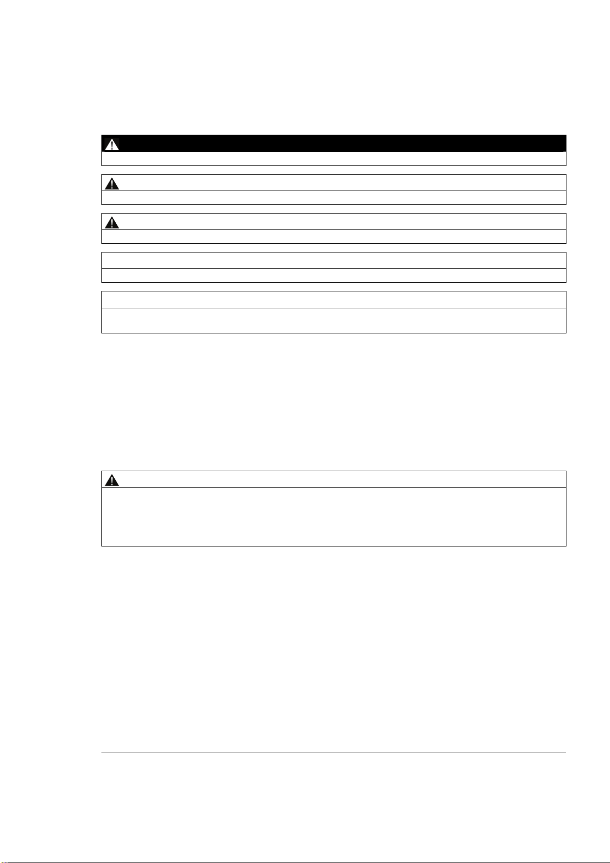
The pressure piece set takes on the direct introduction of force into the load cells.
The pressure piece set has the following features:
● Easy installation of the load cell
● Provides a rotation lock for the load cell
● Has a self-centering effect on the load bearing implement
Pressure piece set for SIWAREX WL270 CP-S SB
The self-centering pressure piece set for SIWAREX WL270 CP-S SB load cells is especially
well suited for installation in vehicle scales, platform weighing machines, and container
weighers.
3
Figure 3-1 Pressure piece set with load cell
CP-S SB
Operating Instructions, 11/2010, A5E03323543B
9

Description
3.1 Application
WARNING
Danger to life from collapse of the structure
Without any protective measures the structure can collapse if the load cell is not installed
correctly. Therefore supporting structures complying with the general rules of mechanical
engineering must be designed by the customer for installing the pressure piece set.
As an alternative installation units from the product range of Siemens can be used.
3.1.2 Lifting protection
The lifting protection prevents the load bearing implements from being lifted off of the load
cells.
If there is a risk of the load bearing implement being lifted or toppled, then lifting protection is
required. This is required in the case of lightweight containers and tall, outdoor silos.
3.1.3 Overload protection
The overload protection protects load cells from a load that is too great.
There is overload protection against excessive loads in the measuring direction and overload
protection against excessive transverse forces.
Transverse forces are caused by, for example, wind, filling processes, acceleration, or
conveyor belt friction. If these forces exceed certain values, the load cells must be protected
from them.
CP-S SB
10 Operating Instructions, 11/2010, A5E03323543B
Description
3.2 Layout and function
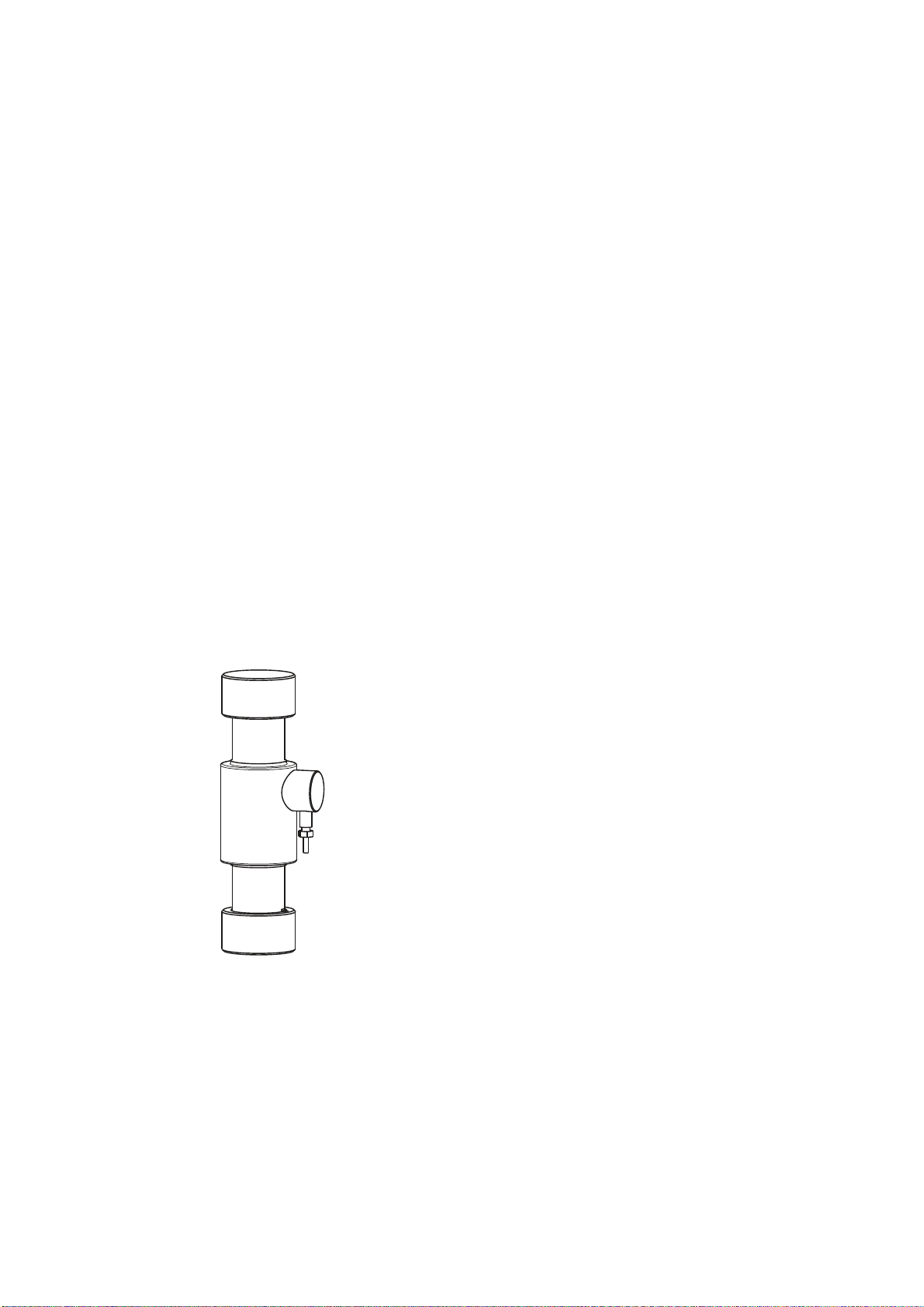
3.1.4 Use of the grounding cable
The grounding cable is used to protect the load cells from undesired currents. The causes of
such currents are, for example:
● Equalizing currents with missing or faulty equipotential bonding conductors.
● A lightning strike nearby
● Welding work
● Static charge
Figure 3-2 Example usage of the grounding cable
3.2 Layout and function
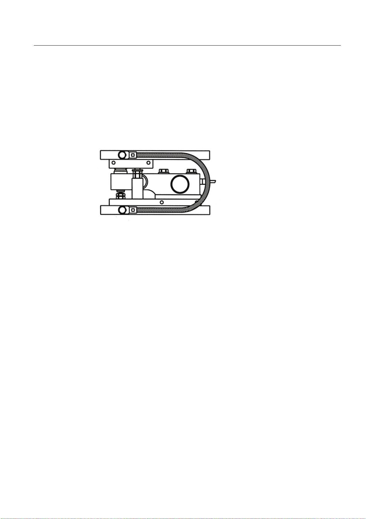
3.2.1 Design and function of the pressure piece set
Design
The pressure piece set is made up of the following components:
● Upper pressure piece
● Lower twist-proof pressure piece
Together with the load cell, the pressure piece set represents a self-centering bearing unit.
①
④
CP-S SB
Operating Instructions, 11/2010, A5E03323543B
11
Description
3.2 Layout and function
① Upper pressure piece
② Load cell, not included in the scope of delivery
③ Pin in lower pressure piece: Prevents the load cell from twisting
④ Lower twist-proof pressure piece
Figure 3-3 Exploded view: Pressure piece set with installed load cell
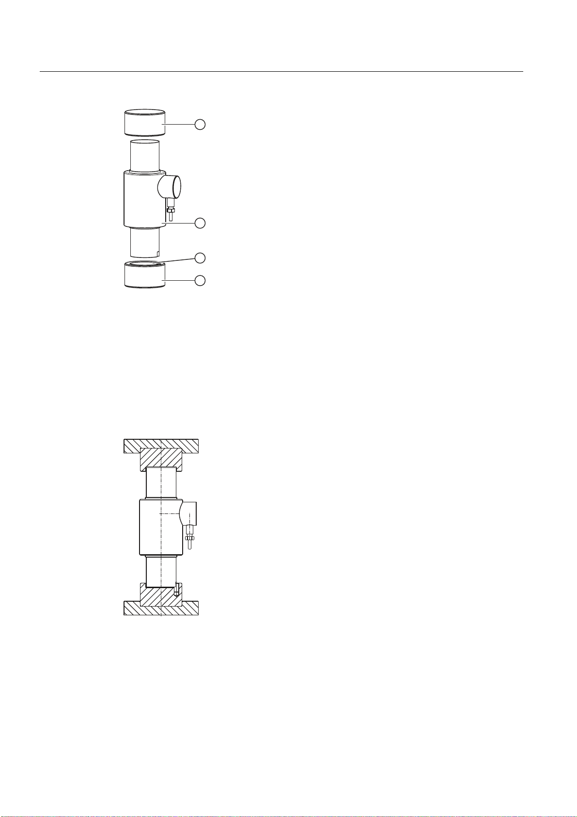
Principle of operation
The pressure pieces ensure the lateral guidance of the load cells and, together with the load
cell, form a self-centering unit.
Figure 3-4 Sectional view
CP-S SB
12 Operating Instructions, 11/2010, A5E03323543B
 Loading...