

Siemens SIWAREX WL260 SP-S AA, SIWAREX WL260 SP-S SA, SIWAREX WL260 SP-S AB, SIWAREX WL260 SP-S AE, SIWAREX WL260 SP-S SB Operating Instructions Manual
...
IWAREX WL200
___________________
___________________
___________________
___________________
___________________
___________________
___________________
___________________
___________________
___________________
___________________
___________________
Weighing systems
Load cells SIWAREX WL200
Operating Instructions
07/2016
A5E02199611B
Introduction
1
Safety instructions
2
Description
3
Installing
4
Connecting
5
Commissioning
6
Service and maintenance
7
Error messages and
troubleshooting
8
Technical data
9
Dimension drawings
10
Ordering data
11
Appendix
A
-03
Siemens AG
Division Process Industries and Drives
Postfach 48 48
90026 NÜRNBERG
GERMANY
Document order number: A5E02199611B-08
Ⓟ
Copyright © Siemens AG 2008 - 2016.
All rights reserved
Legal information
Warning notice system
DANGER
indicates that death or severe personal injury will result if proper precautions are not taken.
WARNING
indicates that death or severe personal injury may result if proper precautions are not taken.
CAUTION
indicates that minor personal injury can result if proper precautions are not taken.
NOTICE
indicates that property damage can result if proper precautions are not taken.
Qualified Personnel
personnel qualified
Proper use of Siemens products
WARNING
Siemens products may only be used for the applications described in the catalog and in the relevant technical
enance are required to ensure that the products operate safely and without any problems. The permissible
ambient conditions must be complied with. The information in the relevant documentation must be observed.
Trademarks
Disclaimer of Liability
This manual contains notices you have to observe in order to ensure your personal safety, as well as to prevent
damage to property. The notices referring to your personal safety are highlighted in the manual by a safety alert
symbol, notices referring only to property damage have no safety alert symbol. These notices shown below are
graded according to the degree of danger.
If more than one degree of danger is present, the warning notice representing the highest degree of danger will
be used. A notice warning of injury to persons with a safety alert symbol may also include a warning relating to
property damage.
The product/system described in this documentation may be operated only by
task in accordance with the relevant documentation, in particular its warning notices and safety instructions.
Qualified personnel are those who, based on their training and experience, are capable of identifying risks and
avoiding potential hazards when working with these products/systems.
Note the following:
documentation. If products and components from other manufacturers are used, these must be recommended
or approved by Siemens. Proper transport, storage, installation, assembly, commissioning, operation and
maint
All names identified by ® are registered trademarks of Siemens AG. The remaining trademarks in this publication
may be trademarks whose use by third parties for their own purposes could violate the rights of the owner.
We have reviewed the contents of this publication to ensure consistency with the hardware and software
described. Since variance cannot be precluded entirely, we cannot guarantee full consistency. However, the
information in this publication is reviewed regularly and any necessary corrections are included in subsequent
editions.
for the specific
07/2016 Subject to change

Table of contents
1 Introduction ............................................................................................................................................. 7
2 Safety instructions ................................................................................................................................... 9
3 Description ............................................................................................................................................ 13
4 Installing ............................................................................................................................................... 17
5 Connecting ........................................................................................................................................... 21
6 Commissioning ..................................................................................................................................... 27
1.1 Purpose of this documentation ................................................................................................. 7
1.2 History ....................................................................................................................................... 7
1.3 Checking the consignment ....................................................................................................... 8
1.4 Transportation and storage ....................................................................................................... 8
1.5 Notes on warranty ..................................................................................................................... 8
2.1 Prerequisites for safe use ......................................................................................................... 9
2.1.1 Laws and directives .................................................................................................................. 9
2.1.2 Conformity with European directives ........................................................................................ 9
2.2 Improper device modifications ................................................................................................ 10
2.3 Requirements for special applications .................................................................................... 10
2.4 Use in hazardous areas .......................................................................................................... 10
3.1 Range of application ............................................................................................................... 13
3.2 Design and principle of operation ........................................................................................... 13
3.3 Nameplate layout .................................................................................................................... 15
4.1 Basic safety instructions ......................................................................................................... 17
4.2 Procedure for mounting the device ......................................................................................... 18
4.3 Dismantling ............................................................................................................................. 19
5.1 Basic safety instructions ......................................................................................................... 21
5.2 Connecting principle ............................................................................................................... 22
5.3 Connecting up ......................................................................................................................... 24
6.1 Basic safety instructions ......................................................................................................... 27
6.2 Application planning ................................................................................................................ 27
6.2.1 Planning .................................................................................................................................. 27
6.2.2 Transverse forces and overload protection ............................................................................ 29
6.2.3 Lengthening and shortening the connecting cable ................................................................. 31
6.3 Adjustment and initial commissioning ..................................................................................... 33
6.3.1 Height compensation .............................................................................................................. 33
SIWAREX WL200
Operating Instructions, 07/2016, A5E02199611B-03
3

Table of contents
7 Service and maintenance ...................................................................................................................... 39
8 Error messages and troubleshooting ..................................................................................................... 41
9 Technical data ...................................................................................................................................... 45
6.3.1.1 When is height compensation necessary? ............................................................................ 33
6.3.1.2 Procedure for height compensation ....................................................................................... 33
6.3.2 Initial commissioning .............................................................................................................. 34
6.3.3 Corner load adjustment .......................................................................................................... 34
6.3.3.1 When is corner load adjustment necessary? ......................................................................... 34
6.3.3.2 General procedure for corner load adjustment ...................................................................... 35
6.3.3.3 Example for corner load adjustment ...................................................................................... 35
7.1 Basic safety instructions ........................................................................................................ 39
7.2 Cleaning ................................................................................................................................. 39
7.3 Return procedure ................................................................................................................... 39
7.4 Disposal ................................................................................................................................. 40
8.1 Repair ..................................................................................................................................... 41
8.2 Error messages ...................................................................................................................... 41
8.3 Checking the mechanical and electrical configuration ........................................................... 41
8.4 Checking the load cells .......................................................................................................... 42
8.5 Measures in the event of overloaded load cells ..................................................................... 43
9.1 Functional data....................................................................................................................... 45
9.1.1 SIWAREX WL260 SP-S AA ................................................................................................... 45
9.1.2 SIWAREX WL260 SP-S AB ................................................................................................... 46
9.1.3 SIWAREX WL260 SP-S AE ................................................................................................... 47
9.1.4 SIWAREX WL260 SP-S SA ................................................................................................... 48
9.1.5 SIWAREX WL260 SP-S SB ................................................................................................... 49
9.1.6 SIWAREX WL260 SP-S SC ................................................................................................... 50
9.1.7 SIWAREX WL250 ST-S SA ................................................................................................... 51
9.1.8 SIWAREX WL230 BB-S SA ................................................................................................... 52
9.1.9 SIWAREX WL230 SB-S CA ................................................................................................... 53
9.1.10 SIWAREX WL230 SB-S SA ................................................................................................... 55
9.1.11 SIWAREX WL270 CP-S SA ................................................................................................... 56
9.1.12 SIWAREX WL270 CP-S SB ................................................................................................... 57
9.1.13 SIWAREX WL270 CP-S SC .................................................................................................. 58
9.1.14 SIWAREX WL270 K-S CA ..................................................................................................... 59
9.1.15 SIWAREX WL280 RN-S SA .................................................................................................. 62
9.1.16 SIWAREX WL290 DB-S CA .................................................................................................. 63
9.2 Electrical specifications .......................................................................................................... 64
9.3 Approval to OIML R60 ........................................................................................................... 65
9.4 Electromagnetic compatibility ................................................................................................ 66
9.5 Certificates and approvals for explosion protection ............................................................... 67
SIWAREX WL200
4 Operating Instructions, 07/2016, A5E02199611B-03

Table of contents
10 Dimension drawings .............................................................................................................................. 69
11 Ordering data ........................................................................................................................................ 91
A Appendix............................................................................................................................................... 99
Index................................................................................................................................................... 101
10.1 SIWAREX WL260 SP-S AA .................................................................................................... 69
10.2 SIWAREX WL260 SP-S AB .................................................................................................... 70
10.3 SIWAREX WL260 SP-S AE .................................................................................................... 70
10.4 SIWAREX WL260 SP-S SA .................................................................................................... 71
10.5 SIWAREX WL260 SP-S SB .................................................................................................... 72
10.6 SIWAREX WL260 SP-S SC ................................................................................................... 73
10.7 SIWAREX WL250 ST-S SA .................................................................................................... 74
10.8 SIWAREX WL230 BB-S SA .................................................................................................... 75
10.9 SIWAREX WL230 SB-S CA ................................................................................................... 76
10.10 SIWAREX WL230 SB-S SA .................................................................................................... 77
10.11 SIWAREX WL270 CP-S SA ................................................................................................... 78
10.12 SIWAREX WL270 CP-S SB ................................................................................................... 79
10.13 SIWAREX WL270 CP-S SC ................................................................................................... 80
10.14 SIWAREX WL270 K-S CA ...................................................................................................... 81
10.15 SIWAREX WL280 RN-S SA ................................................................................................... 83
10.16 SIWAREX WL290 DB-S CA ................................................................................................... 89
11.1 Load cells ................................................................................................................................ 91
11.2 Accessories ............................................................................................................................. 98
A.1 Technical support .................................................................................................................... 99
SIWAREX WL200
Operating Instructions, 07/2016, A5E02199611B-03
5

Table of contents
SIWAREX WL200
6 Operating Instructions, 07/2016, A5E02199611B-03

1
1.1
Purpose of this documentation
See also
1.2
History
Edition
Remarks/changes
Additions to explosion protection and ATEX approval
07/2010
Addition to WL280 RN-S SA 10 t; 13 t; 28 t and 60 t load cells.
Addition to WL270 K-S CA load cells
S CA load cells with additional versions (high temperature, double
cells and WL260 SP-S SC load cells.
09/2013
Expansion of the load cells WL270 K and WL280 RN for hazardous areas
11/2013
Dimensions of WL250 ST-S SA changed.
11/2014
Integration of load cell WL260 SP-S AE
General formal changes.
05/2016
Addition to load cell WL290 DB-S CA
These instructions contain all information required to commission and use the device. Read
the instructions carefully prior to installation and commissioning. In order to use the device
correctly, first review its principle of operation.
The instructions are aimed at persons mechanically installing the device, connecting it
electronically, configuring the parameters and commissioning it, as well as service and
maintenance engineers.
Technical support (Page 99)
The following versions of this documentation have been released to date. The changes apply
to the previous version:
Table 1- 1 History
10/2008 Initial release
04/2009 Addition to SP-S SA 30 t load cell.
Designation updated: WL200 instead of WL 200.
Corrections made mainly to the specifications.
09/2010 Addition to WL280 RN-S SA 60 kg to 5 t load cells
02/2013 WL270 K-
bridge) and extended operating range up to 500 t. WL260 SP-S SB load
03/2015 Integration of load cell WL230 SB-S CA. Description of nameplate und
ATEX label.
SIWAREX WL200
Operating Instructions, 07/2016, A5E02199611B-03
7
Introduction
1.3
Checking the consignment
WARNING
Using a damaged or incomplete device
1.4
Transportation and storage
CAUTION
Insufficient protection during storage
1.5
Notes on warranty
1.3 Checking the consignment
1. Check the packaging and the delivered items for visible damage.
2. Report any claims for damages immediately to the shipping company.
3. Retain damaged parts for clarification.
4. Check the scope of delivery by comparing your order to the shipping documents for
correctness and completeness.
Danger of explosion in hazardous areas.
• Do not use damaged or incomplete devices.
To guarantee sufficient protection during transport and storage, observe the following:
● Keep the original packaging for subsequent transportation.
● Devices/replacement parts should be returned in their original packaging.
● If the original packaging is no longer available, ensure that all shipments are properly
packaged to provide sufficient protection during transport. Siemens cannot assume
liability for any costs associated with transportation damages.
The packaging only provides limited protection against moisture and infiltration.
• Provide additional packaging as necessary.
Special conditions for storage and transportation of the device are listed in Technical data
(Page 45).
The contents of this manual shall not become part of or modify any prior or existing
agreement, commitment or legal relationship. The sales contract contains all obligations on
the part of Siemens as well as the complete and solely applicable warranty conditions. Any
statements regarding device versions described in the manual do not create new warranties
or modify the existing warranty.
The content reflects the technical status at the time of publishing. Siemens reserves the right
to make technical changes in the course of further development.
SIWAREX WL200
8 Operating Instructions, 07/2016, A5E02199611B-03
2
2.1
Prerequisites for safe use
Symbol
Explanation
2.1.1
Laws and directives
2.1.2
Conformity with European directives
Electromagnetic compatibi
ity EMC
2014/30/EU
Directive of the European Parliament and of the Council on the
approximation of the laws of the Member States relating to electromagnetic compatibility and repealing Directive 89/336/EEC.
Atmosphè
ATEX
2014/34/EU
Directive of the European Parliament and the Council on the
a
equi
ly explosive atmospheres.
This device left the factory in good working condition. In order to maintain this status and to
ensure safe operation of the device, observe these instructions and all the specifications
relevant to safety.
Observe the information and symbols on the device. Do not remove any information or
symbols from the device. Always keep the information and symbols in a completely legible
state.
Consult operating instructions
Observe the test certification, provisions and laws applicable in your country during
connection, assembly and operation. These include, for example:
● National Electrical Code (NEC - NFPA 70) (USA)
● Canadian Electrical Code (CEC) (Canada)
Further provisions for hazardous area applications are for example:
● IEC 60079-14 (international)
● EN 60079-14 (EC)
The CE mark on the device is a sign of conformity with the following European directives:
l-
re explosible
pproximation of the laws of the Member States concerning
pment and protective systems intended for use in potential-
The standards applied can be found in the EC declaration of conformity for the device.
SIWAREX WL200
Operating Instructions, 07/2016, A5E02199611B-03
9
Safety instructions
2.2
Improper device modifications
WARNING
Improper device modifications
2.3
Requirements for special applications
Note
Operation under special ambient conditions
We highly recommend that you contact your Siemens representative or our application
department before you operate the device under special ambient conditions as can be
encountered in nuclear power plants or when the device
development purposes.
2.4
Use in hazardous areas
Qualified personnel for hazardous area applications
2.2 Improper device modifications
Danger to personnel, system and environment can result from modifications to the device,
particularly in hazardous areas.
• Only carry out modifications that are described in the instructions for the device. Failure
to observe this requirement cancels the manufacturer's warranty and the product
approvals.
Due to the large number of possible applications, each detail of the described device
versions for each possible scenario during commissioning, operation, maintenance or
operation in systems cannot be considered in the instructions. If you need additional
information not covered by these instructions, contact your local Siemens office or company
representative.
is used for research and
Persons who install, connect, commission, operate, and service the device in a hazardous
area must have the following specific qualifications:
● They are authorized, trained or instructed in operating and maintaining devices and
systems according to the safety regulations for electrical circuits, high pressures,
aggressive, and hazardous media.
● They are authorized, trained, or instructed in carrying out work on electrical circuits for
hazardous systems.
● They are trained or instructed in maintenance and use of appropriate safety equipment
according to the pertinent safety regulations.
SIWAREX WL200
10 Operating Instructions, 07/2016, A5E02199611B-03
Safety instructions
WARNING
Unsuitable device for the hazardous area
WARNING
Loss of safety of device with type of protection "Intrinsic safety Ex i"
NOTICE
Damage to load cells, measurement errors
2.4 Use in hazardous areas
Danger of explosion.
• Only use equipment that is approved for use in the intended hazardous area and
labelled accordingly.
If the device has already been operated in non-intrinsically safe circuits or the electrical
specifications have not been observed, the safety of the device is no longer ensured for use
in hazardous areas. There is a danger of explosion.
• Connect the device with type of protection "Intrinsic safety" solely to an intrinsically safe
circuit.
• Observe the specifications for the electrical data on the certificate and/or in Technical
data (Page 45).
Dirt must not be allowed to accumulate in the vicinity of a load cell.
Do not subject cable glands and seals to the jet from a pressure washer.
SIWAREX WL200
Operating Instructions, 07/2016, A5E02199611B-03
11

Safety instructions
2.4 Use in hazardous areas
SIWAREX WL200
12 Operating Instructions, 07/2016, A5E02199611B-03
3
3.1
Range of application
3.2
Design and principle of operation
Design
SIWAREX load cells are used for measuring forces and weights statically and dynamically.
You can use SIWAREX load cells for almost all applications in industrial weighing
technology. Examples include:
● Container weighers, hopper scales or platform scales,
● Roller table, conveyor or crane scales,
● Plants for bottling/packing, dosing and mixing,
● for checking levels and completeness,
● Equipment for monitoring pressing or stretching processes,
● Dynamic scales
All applications can be implemented in equipment requiring official calibration or in areas
subject to explosion hazards.
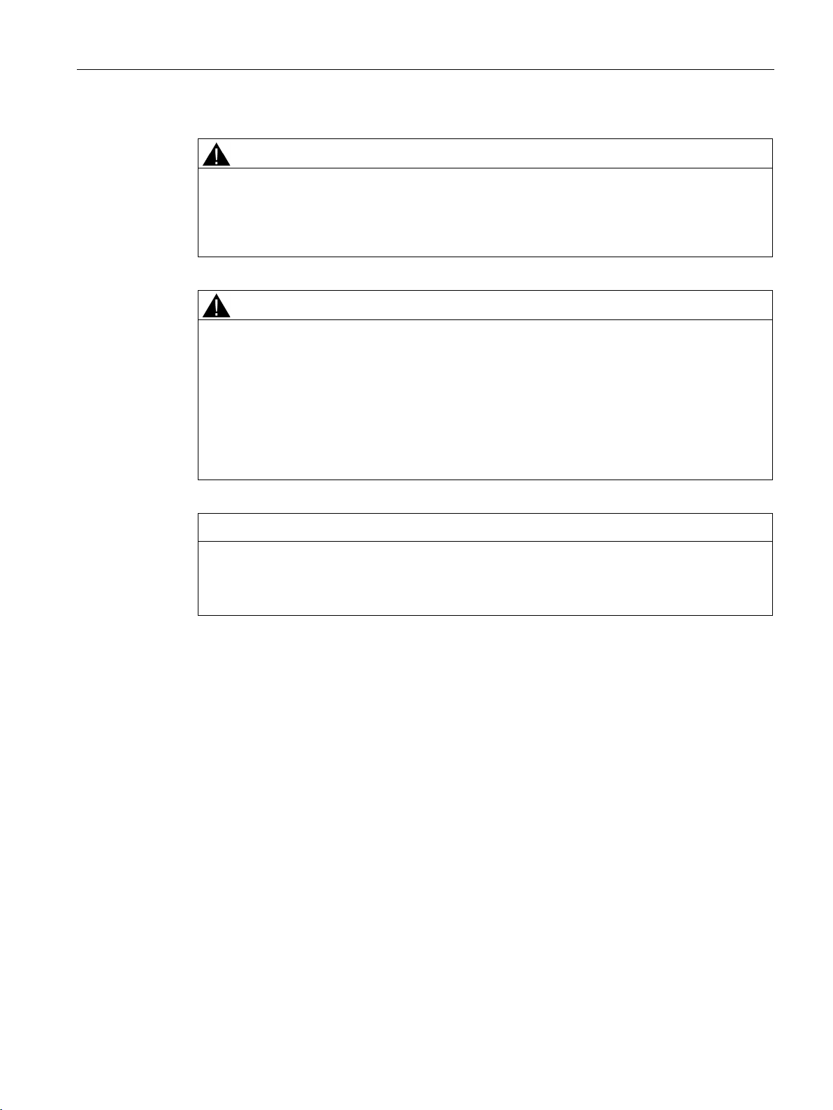
SIWAREX load cells are based on strain gauges. Strain-gauge load cells are transducers
which convert mechanical forces into electrical signals. The principle of operation is the
same regardless of variations in design.
Figure 3-1 Design, based on the example of an unloaded bending beam load cell
SIWAREX WL200
Operating Instructions, 07/2016, A5E02199611B-03
13
Description
Principle of operation
3.2 Design and principle of operation
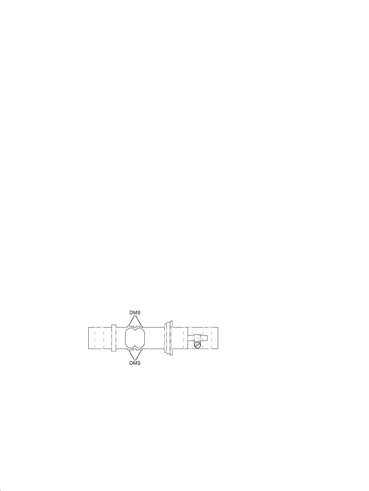
The basic component in each case is a special type of spring body. The application of force
elastically deforms the spring body. The ohmic resistance of the strain gauges changes as a
result.
Figure 3-2 Principle of operation, based on the example of a loaded bending beam load cell
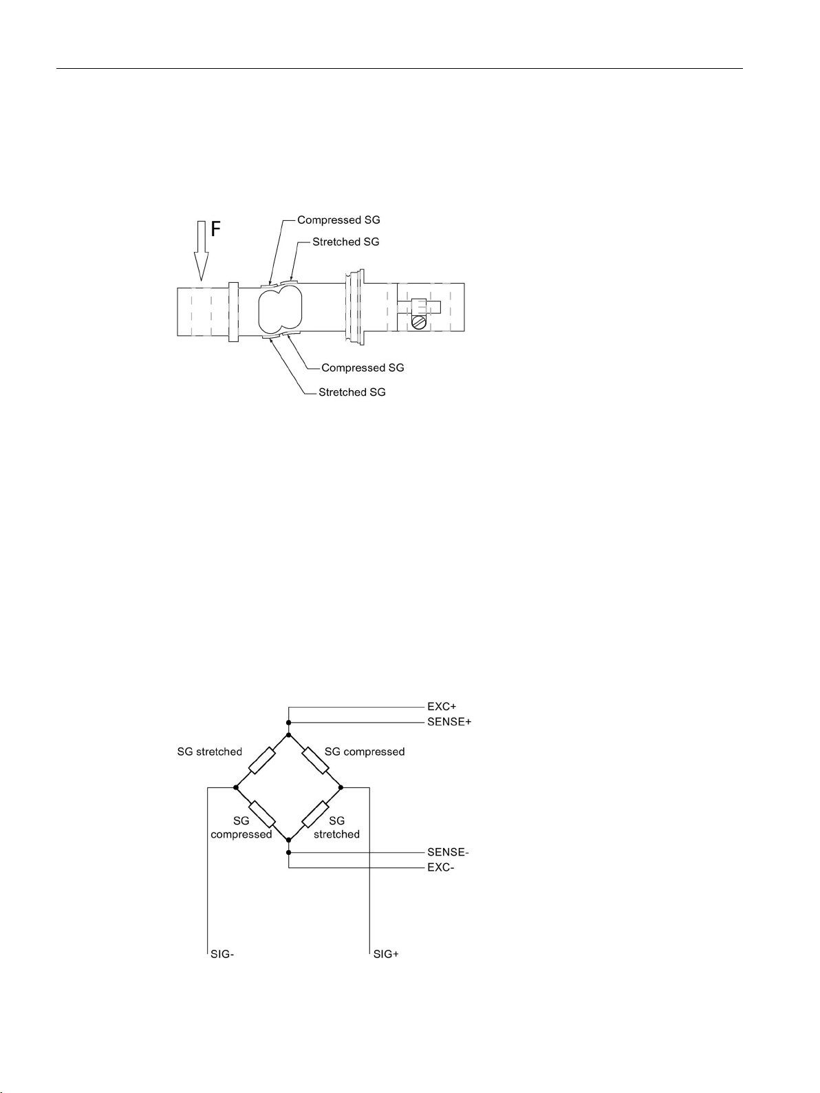
For each load cell, at least four strain gauges are connected together as a complete
Wheatstone bridge. The stretched or compressed strain gauges are connected in such a
manner that the positive or negative resistance changes are summed to produce an overall
imbalance of the bridge.
The supply voltage is applied across one diagonal of the bridge and, in the case of the sixwire connection method, also the sensor voltage SENSE. The measured voltage is tapped
across the other diagonal.
For a constant supply voltage EXC, therefore, the measured voltage SIG changes
proportionally to the introduced load. In practice, load cells contain additional resistors for
temperature compensation and for zero-signal and characteristic-value compensation.
Depending on their type and the requirements, these resistors can be arranged at the input
or output of the load cell.
Figure 3-3 The principle of a Wheatstone bridge
SIWAREX WL200
14 Operating Instructions, 07/2016, A5E02199611B-03
Description
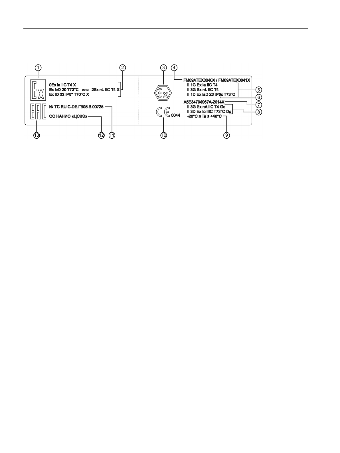
3.3
Nameplate layout
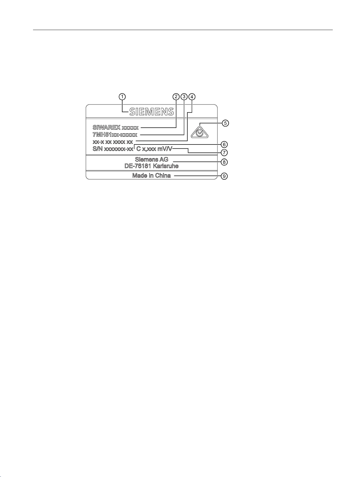
①
Company logo
②
Product group designation
③
Order number
④
Product designation
⑤
RCM
⑥
Serial number
⑦
Rated characteristic value Cn of load cell
⑧
Manufacturer's address
⑨
Country of origin
nameplate layout with general information
3.3 Nameplate layout
Nameplate layout with general information
Figure 3-4 Example of
SIWAREX WL200
Operating Instructions, 07/2016, A5E02199611B-03
15
Description
Nameplate layout with approval information
①
Ex marking of the customs union
②
Types of protection of the customs union
③
Ex marking (ATEX)
④
Numbers of ATEX approvals
⑤
Type of protection according to ATEX
⑥
Degree of protection according to EN 60 529, e.g. IP67. The degree of protection depends on the type of load cell.
⑦
Number of the manufacturer's declaration for zone 2
⑧
Type of protection according to ATEX
⑨
Permitted temperature range
⑩
CE mark
⑪
Number of the certificate of the customs union
⑫
Notified body of the customs union
⑬
EAC marking of the customs union
See also
3.3 Nameplate layout
Figure 3-5 Example of nameplate layout with approval information
Adjustment and initial commissioning (Page 33)
SIWAREX WL200
16 Operating Instructions, 07/2016, A5E02199611B-03
4
4.1
Basic safety instructions
DANGER
Danger to life from falling loads
NOTICE
Damage to load cells through incorrect handling
NOTICE
Damage to load cells through high currents
Load cells are precision components and must therefore be handled carefully. Particular
care must be taken during transport and installation.
• Load cells are not machine components which have been constructed with the normal
safety factors. For this reason, appropriate protection against falling and catastrophes
must be implemented in accordance with the potential risks.
• Use suitable hoisting equipment to lift the load carrier. Observe the appropriate safety
regulations.
• SIWAREX load cells are only permitted to be mounted and connected by qualified
personnel.
• Mechanical shocks or falls can irreparably damage the load cell.
• When mounting the load cell, ensure that you do not damage or cut the cables of the
load cell. Load cells must not be carried by their connecting cables.
• Protect the load cells from shocks and welding currents. Replace the load cells with
dummies until the installation work on the scale structure is completed.
• If welding is undertaken after the load cells have been installed, ensure that the welding
current is not diverted through the load cells.
– You can do this by attaching the grounding clamp of the welding unit making reliable
contact close to the weld.
– Bridge the load cells with a ground cable, for more on this, see Accessories
(Page 98)
– Disconnect the individual load cells.
• Undesirable electrical currents can arise during lightning. Bridge the load cells with a
highly flexible ground cable to protect the load cells against such currents, for more on
this, see Accessories (Page 98).
SIWAREX WL200
Operating Instructions, 07/2016, A5E02199611B-03
17

Installing
NOTICE
Damage to load cells through incorrect mounting
expansion will not result in lateral loading.
NOTICE
Destruction of load cells
4.2
Procedure for mounting the device
Procedure for mounting the device
See also
4.2 Procedure for mounting the device
• Provide indented claws or crane eyebolts on the load bearer to ensure that hoisting gear
can be used safely.
• Load cells must never be overloaded. Put the load carrier down slowly for this reason.
With load cells of smaller rated loads in particular, there is a risk of stretching the load
cell bodies when attaching force transfer devices, e.g. when tightening locknuts.
• Adjust the existing overload protection to ensure that it can still reliably sense transfer of
the required load. The overload protection must permit a rise in weight unhindered until
the setpoint weight is reached.
• Protect the gap between the load cell and overload protection from the build up of dirt or
ice.
• The load must be introduced in the measuring direction of the load cell. Torsional and
bending moments, eccentric loads and lateral forces are disturbances. These
disturbances falsify the measured result and can damage the load cell if the permissible
limits of the load cell and mounting components are exceeded.
The mounting components normally allow so much room for movement that heat
Proceed carefully with installation. The load cells can be destroyed if they are installed
incorrectly.
1. Observe the installation guidelines for the mounting components.
– You can find dimension drawings of installation elements under Dimension drawings
(Page 69).
– Lay the cables for the load cells through cable glands in the form of a vertical
downwards loop to discourage the penetration of water.
2. Check that the load cells and mounting components are installed correctly, e.g. by
checking the mounting dimensions and oscillation distances.
Nameplate layout (Page 15)
SIWAREX WL200
18 Operating Instructions, 07/2016, A5E02199611B-03

Installing
4.3
Dismantling
4.3 Dismantling
For the disassembly of load cells, the same safety rules and requirements apply as for
installation and assembly.
1. Disconnect all the supply voltages and auxiliary voltages.
2. Secure the load carrier against falling.
3. Use appropriate hoisting gear and tools.
4. Take the load off the load cell.
5. Carefully remove the load cell without using force. Do not pull on the cable of the load
cell.
6. Do not cut the cable if the load cell is to be re-used or sent in for repair.
7. Do not carry the load cell by the cable.
SIWAREX WL200
Operating Instructions, 07/2016, A5E02199611B-03
19

Installing
4.3 Dismantling
SIWAREX WL200
20 Operating Instructions, 07/2016, A5E02199611B-03
5
5.1
Basic safety instructions
WARNING
Incorrect selection of type of protection
WARNING
Improper power supply
Note
Electromagnetic compatibility (EMC)
You can
For metal housings there is an increased electromagnetic compatibility compared to high
frequency radiation. This protection can be increased by grounding the housing, see
Connecting
Danger of explosion in areas subject to explosion hazard.
This device is approved for several types of protection.
1. Decide in favor of one type of protection.
2. Connect the device in accordance with the selected type of protection.
3. In order to avoid incorrect use at a later point, make the types of protection that are not
used permanently unrecognizable on the nameplate.
Danger of explosion in hazardous areas as result of incorrect power supply, e.g. using
direct current instead of alternating current.
• Connect the device in accordance with the specified power supply and signal circuits.
The relevant specifications can be found in the certificates, in Technical data (Page 45)
or on the nameplate.
use this device in industrial environments, households and small businesses.
-
(Page 21).
SIWAREX WL200
Operating Instructions, 07/2016, A5E02199611B-03
21
Connecting
5.2
Connecting principle
WARNING
Risk of explosion
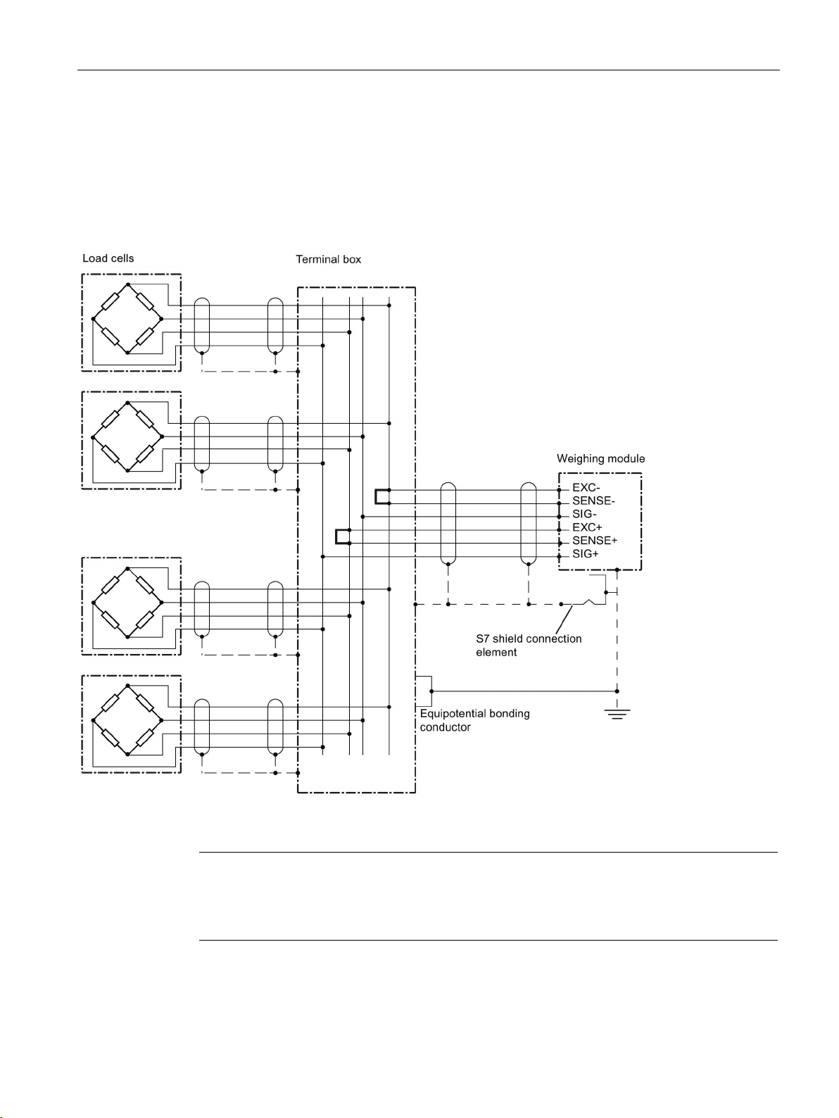
5.2 Connecting principle
Load cells can be equipped with connecting cables with four or six cores.
Please observe that in the case of shielded cables of intrinsically safe circuits in hazardous
areas only one grounding is permissible.
If grounding is to be on both sides an equipotential bonding conductor with at least 4 mm²
must be connected.
SIWAREX WL200
22 Operating Instructions, 07/2016, A5E02199611B-03
Connecting
Load cells with four-wire system
Note
No calibration approval
In scales requiring official calibration, the connecting cables for load cells in a four
system must not be shortened or lengthened.
5.2 Connecting principle
Do not shorten or length connecting cables in the four-wire system, because the cable
resistance is temperature compensated. When the length of the connecting cable is altered,
the input and output resistances change. This change can be corrected by adjusting the
scale, but temperature-dependent resistance changes are not compensated for the missing
or additional length of cable.
Figure 5-1 Connecting principle for load cells with four-wire system
SIWAREX WL200
Operating Instructions, 07/2016, A5E02199611B-03
-wire
23
Connecting
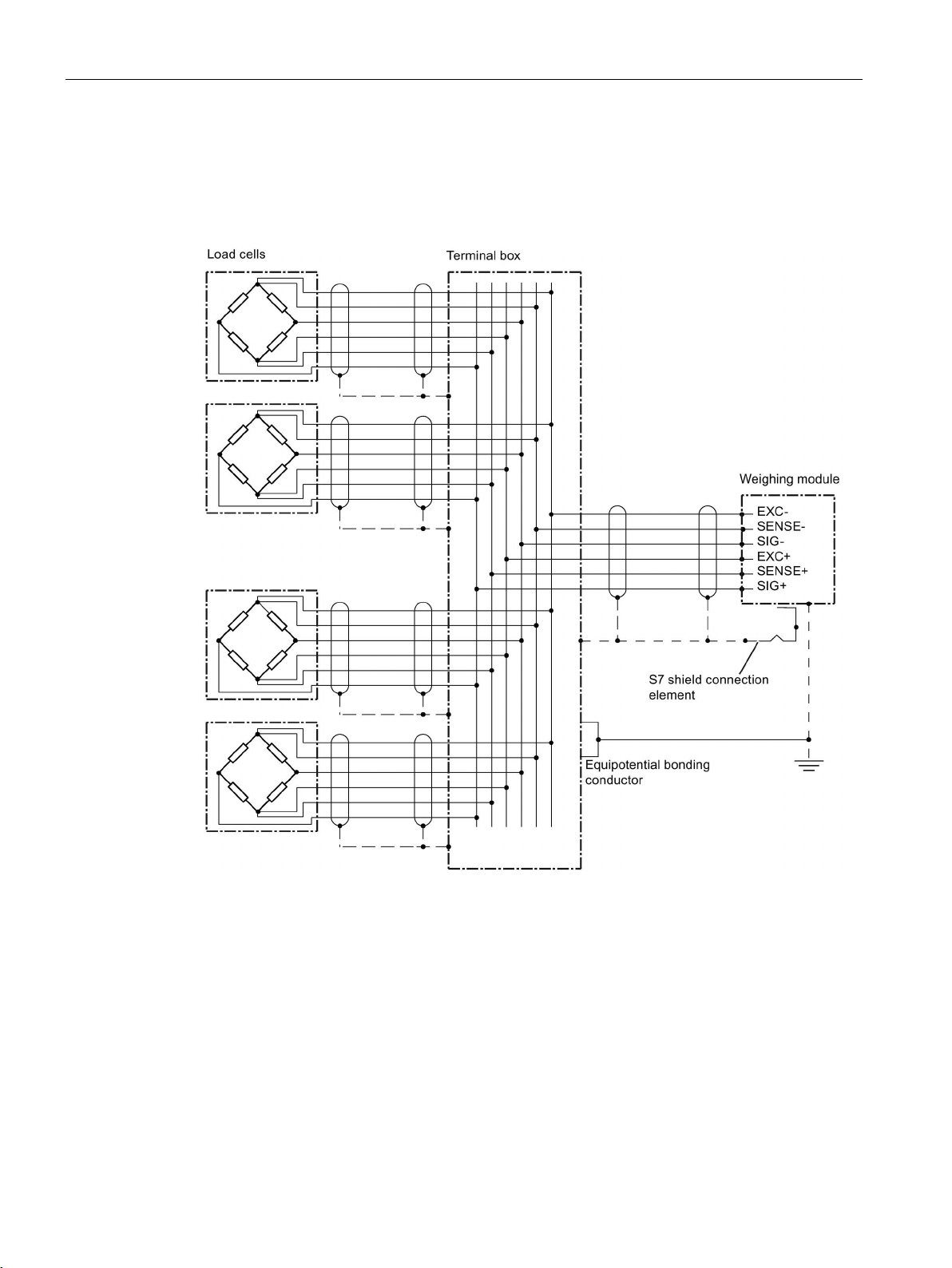
Load cells with six-wire system
5.3
Connecting up
Signal assignment for the load cell connecting cable
5.3 Connecting up
For connecting cables in the six-wire system, the supply voltage is fed back to the weighing
module as the reference voltage. Shortening or lengthening has no effect on the measuring
result.
Figure 5-2 Connecting principle for load cells with six-wire system
Identifying colors and signal assignment for the connecting cables of load cells not listed:
See the data sheet for the appropriate load cell.
SIWAREX WL200
24 Operating Instructions, 07/2016, A5E02199611B-03
Connecting
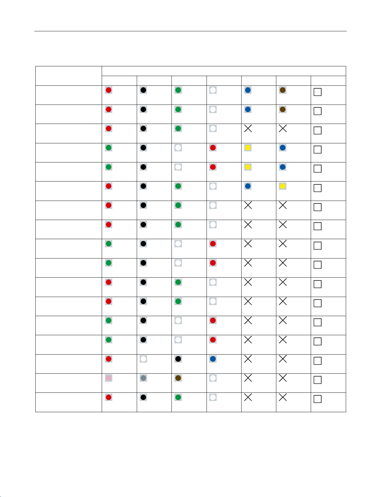
Load cell
Function/color of connecting cable
EXC+
EXC-
SIG+
SIG-
Sense+
Sense-
Shield
parent
parent
parent
parent
parent
parent
parent
5.3 Connecting up
Table 5- 1 Signal assignment for the load cell connecting cable
SIWAREX WL260
SP-S AA
SIWAREX WL260
SP-S AB
SIWAREX WL260
SP-S AE
SIWAREX WL260
SP-S SA
SIWAREX WL260
SP-S SB
SIWAREX WL260
SP-S SC 10 ... 50 kg
SIWAREX WL260
SP-S SC 100 ... 200 kg
SIWAREX WL250
ST-S SA
SIWAREX WL230
BB-S SA
SIWAREX WL230
SB-S SA
SIWAREX WL230
SB-S CA
SIWAREX WL270
CP-S SA
Red Black Green White Blue Brown
Red Black Green White Blue Brown
Red Black Green White n.a. n.a.
Green Black White Red Green Blue
Green Black White Red Green Blue
Red Black Green White Blue Green
Red Black Green White n.a. n.a.
Red Black Green White n.a. n.a.
Green Black White Red n.a. n.a.
Green Black White Red n.a. n.a.
Red Black Green White n.a. n.a.
Red Black Green White n.a. n.a.
Trans-
parent
Trans-
Trans-
Trans-
parent
Trans-
Trans-
Trans-
parent
Trans-
parent
Trans-
Trans-
parent
Trans-
parent
Trans-
SIWAREX WL270
CP-S SB
SIWAREX WL270
CP-S SC
SIWAREX WL270
K-S CA
SIWAREX WL280
RN-S SA
SIWAREX WL290
DB-S CA
SIWAREX WL200
Operating Instructions, 07/2016, A5E02199611B-03
Green Black White Red n.a. n.a.
Green Black White Red n.a. n.a.
Red White Black Blue n.a. n.a.
Pink Gray Brown White n.a. n.a.
Red Black Green White n.a. n.a.
Trans-
parent
Trans-
parent
Trans-
Trans-
parent
Trans-
parent
25

Connecting
Procedure
Note
Measurement errors
Observe the warnings concerning extending or shortening the connecting cables in section
→
If at all possible, do not shorten the connecting cables in a four
Note
No calibration approval
In scales requiring official calibration, the connecting cables for load cells in a four
system must not be shortened or lengthened.
Wire jumper
From terminal
To terminal
1
EXC-
SENSE-
2
EXC+
SENSE+
Note
Malfunction
If the wire jumpers are missing, the SIWAREX weighing module signals a wire break.
5.3 Connecting up
Lengthening and shortening the connecting cable (Page 31).
-wire system.
-wire
1. Connect the recommended grounding cables: → Planning (Page 27)
2. Connect the load cells in accordance with the connection principle and with reference to
the specified signal assignments: → Connecting principle (Page 22)
3. For load cells with a four-wire system, position the wire jumpers in the junction box as
follows:
Table 5- 2 Wire jumpers for load cells with four-wire system
SIWAREX WL200
26 Operating Instructions, 07/2016, A5E02199611B-03
6
6.1
Basic safety instructions
WARNING
Improper commissioning in hazardous areas
6.2
Application planning
6.2.1
Planning
WARNING
Danger to life from falling loads
Version
Device failure or danger of explosion in hazardous areas.
• Do not commission the device until it has been mounted completely and connected in
accordance with the information in Technical data (Page 45).
• Before commissioning take the effect on other devices in the system into account.
Load cells are not machine components which have been constructed with the normal
safety factors. For this reason, appropriate protection against falling and catastrophes must
be implemented in accordance with the potential risks.
SIWAREX load cells are usually manufactured from stainless steel and hermetically sealed.
This provides a high degree of corrosion resistance and a high degree of protection.
Most type series are approved for use in scales requiring official calibration of Class III to
DIN EN 45501 and comply with the accuracy class OIML R60 C3.
If necessary, load cells can be supplied with ATEX approval.
SIWAREX load cells are current-calibrated as standard. This means that, for example, when
a platform scale is commissioned, corner load adjustment is not necessary. A load cell can
therefore be replaced without recalibration of the scale.
This may not apply to load cells that are available outside the standardized delivery
spectrum. For these load cell types, the relevant technical specifications apply.
SIWAREX WL200
Operating Instructions, 07/2016, A5E02199611B-03
27

Commissioning
Parallel connection of load cells
NOTICE
Overloading of load cells
Note
Measurement errors
Load cells are only permitted to be connected in parallel when they have the same
characteristic value, the same rated load and the same internal resistance.
The total resistance of load
resistance from the technical data of the weighing module to which it should be connected.
Environmental requirements at the mounting location
Note
Measurement errors
The load cell must be protected against direct solar radiation. Otherwise, the permissible
operating temperature may be exceeded. One
measurements or even measurement errors.
6.2 Application planning
In weighing systems, one or more load cells are connected to a weighing module for
evaluation of the measured signal. Several load cells of a scale are connected in parallel to a
junction box to supply a joint output signal.
When more than one load cell is connected to a scale, if the load distribution is uneven, it
cannot be established whether individual load cells are overloaded.
cells connected in parallel must not undershoot the minimum
The maximum number of load cells that can be connected to a weighing module depends on
the total resistance of the load cells connected in parallel. This must lie within the load
resistance limits specified for the weighing module.
The maximum length of the cables and the specifications for other components, e.g. Ex i
interface, must also be complied with. For details, see the section Lengthening and
shortening the connecting cable (Page 31)
The foundations must be unyielding when the expected loads are applied. The maximum
roughness permitted for the mounting surface is 1.6 µm.
The values specified in the technical data for the ambient conditions must be complied with.
-sided heating will result in less accurate
SIWAREX WL200
28 Operating Instructions, 07/2016, A5E02199611B-03

Commissioning
Grounding protection
NOTICE
Damaging of load cells
6.2.2
Transverse forces and overload protection
Overloading of load cells
NOTICE
Risk of overloading
NOTICE
Damage to load cells through overloading
Note
Error message on overload
If load cells are loaded beyond their rated load, this can result in an error message
weighing module.
6.2 Application planning
Undesirable electrical currents can arise during welding or lightning. To protect the load
cells against such currents, bridge the load cells using highly flexible grounding cables, see
also Accessories (Page 98).
If you connect more than one load cell to a scale, if the load distribution is uneven, it cannot
be established whether individual load cells are overloaded.
In the case of load cells with small rated loads, overload protection must be implemented to
protect the cells against damage.
If load cells are used beyond the maximum working load or the maximum lateral load, this
can cause irreparable errors and even fracturing of the load cell.
When mounting components are fitted, the load cells must not be overloaded, e.g. by
overtightening bolts.
in the
Overloading can occur as a result of:
● Uneven load distribution due to mounted components or cones of bulk material
● Rolling/pushing up the load on platform or roller table scales
● Forceful application of the load
● Application of the load in free fall
SIWAREX WL200
Operating Instructions, 07/2016, A5E02199611B-03
29

Commissioning
Dimensioning for overload
Lifting protection
Mounting components and guide elements to counteract lateral forces, torsional and bending
moments
6.2 Application planning
● Persons supporting themselves on or climbing onto the scale
● Wind against the leeward side of a silo
When step changes in load cannot be excluded during measuring, for example, due to
application of a load in free fall, you must take appropriate precautions to avoid damage to
the load cell, e.g. by using elastomer bearings or load cells dimensioned for higher rated
loads.
When dimensioning load cells, include a safety margin to guard against overloading:
● Use a safety margin of 20% in the case of three support points.
● If more than three support points are used in a statically indeterminate manner, the safety
margin must be a minimum of 50% if it is not possible to rule out a situation in which the
load rests on two diagonally opposite load cells only. Reasons for this include sinking of
the foundations or incorrect mounting.
● When calculating the safety margin, include unintentional overloads or overloading
caused by the course of the process, or use overload protection.
Overloads can also occur in the lifting direction when the force introducer is attached to the
load cell.
If there is a risk of the load bearing being lifted or toppled, lifting protection may be
necessary. This is required in the case of lightweight containers and tall, outdoor silos.
The load must be introduced in the measuring direction of the load cell. Torsional and
bending moments, eccentric loads and lateral forces are disturbances that on the one hand
falsify the measured result and on the other hand can damage the load cell if the permissible
limits are exceeded. Load cells must therefore be fitted with specially adapted mounting
components, e.g. with SIWAREX mounting parts. This largely prevents the above-mentioned
sources of error. The mounting components allow so much room for movement that heat
expansion will not result in lateral loading.
Lateral forces which are generated by wind, acceleration or conveyor friction can be diverted
by guide elements or stops.
Guide elements must be installed perpendicular to the measuring direction to ensure that no
force components are generated in the measuring direction. The guide elements must be
installed such that they do not stretch if, for example, the mounting points spread apart. This
is easily achieved by arranging the guide elements in the same direction of rotation.
Ensure that the selected guide elements comply with the principles applicable to weighing
technology.
Force bypasses must not arise due to filling and emptying devices or supply lines.
SIWAREX WL200
30 Operating Instructions, 07/2016, A5E02199611B-03
 Loading...