

Page 1
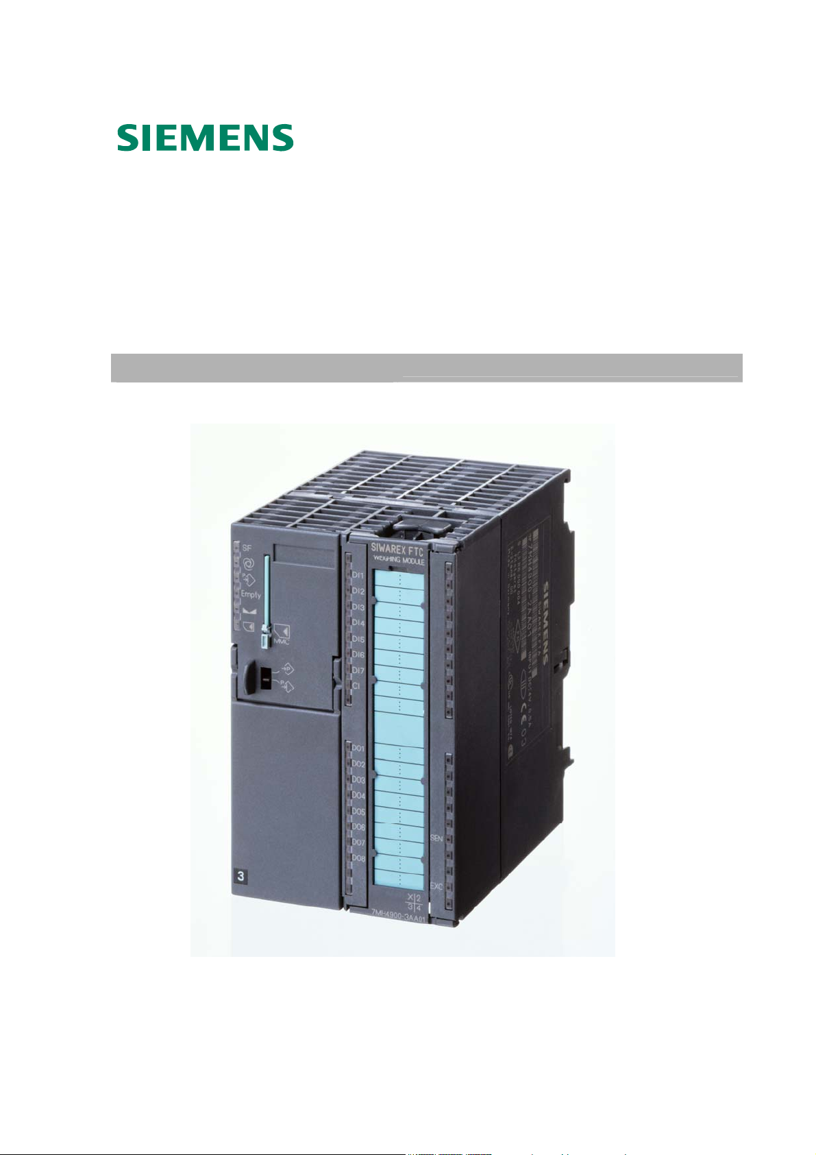
SIWAREX® FTC
Device Manual
Module for Belt scale
Status 10.2010
Page 2

Warning and Safety Terms
This manual contains notices that are for your personal safety and to prevent damage to
devices or surroundings. These notices are indicated by a warning triangle and are presented
as follows depending on the degree of danger:
!
!
!
Danger
means, that death, severe injury or considerable material damage may result, if
the respective safety measures are not taken.
Warning
Means that death, severe injury or serious material damage can result if the corresponding safety
precautions are not followed carefully.
Caution
Means that material damage or minor injuries can result if the corresponding safety precautions are
not followed carefully.
Caution
Means that material damage can result if the corresponding safety precautions
are not followed carefully.
Attention
Refers to important information on the product, handling of a product or a
corresponding segment of the documentation to which special attention should be
given.
Qualified Personnel
Commissioning and operation of a device may only be performed by qualified personnel. Qualified personnel as
indicated in the safety information in this manual are people that have the authorization to install, ground and label
devices, systems and power circuits.
Intended Utilization
Warning
!
Brand names / Trademarks
The device may only be utilized for the applications described in the catalog and the technical
description and only in conjunction with external devices and components that are approved or
recommended by Siemens.
Fault-free and safe operation of the product depend on proper transport, proper storage, assembly,
installation, operation and maintenance.
SIWAREX®, SIMATIC®, SIMATIC HMI® and SIMATIC NET® are trade marks of the
Siemens AG. The other designations in this info may be trade marks the use of which by third
persons for their own purposes might infringe proprietor rights.
Copyright
Circulation or duplication of this document, utilization and
disclosure of its contents are not permitted unless explicitly
approved. Offenders will be liable for damages. All rights
reserved, including rights created by granting of patents or
registration of a utility model or design.
Siemens AG
Automation & Drives Dept.
SIWAREX Weighing Systems
A&D SC PS1 WT
Östliche Rheinbrückenstr. 50
D-76187 Karlsruhe
©
Siemens AG 2006 All rights reserved
Disclaimer
We have tested the contents of this document for compatibility
with the hardware and software described. This does not
exclude the possibility of discrepancies, in which case we do
not guarantee the complete compatibility of this document.
The information in this document is assessed regularly and
any necessary corrections are included in the next revision.
We are grateful for any suggestions for improvement.
© Siemens AG 2007
Subject to change without notice.
iv SIWAREX FTC
Page 3

SIWAREX FTC
SIWAREX FTC
Module for belt scale
Device Manual
Warning and Safety Terms
Contents
Preface
Scope of Delivery
Product Overview
Hardware Configuration and
Assembly
Weighing Functions and Parameters
Commands
Messages and Diagnosis
Programming in SIMATIC STEP 7
Commissioning with a PC –
SIWATOOL FTC_B
Firmware-Update with SIWATOOL
FTC_B
Empty
1
2
3
4
5
6
7
8
9
10
11
Revision 10/2010
Project planning in SIMATIC PCS 7
Accessories
Technical Data
Index
Abbreviations
12
13
14
15
16
SIWAREX FTC v
Page 4

Contents
1 Preface....................................................................................................................................
1.1 ...............................................................................................1-1 PURPOSE OF MANUAL
1.2 ..................................................................................1-1 BASIC KNOWLEDGE REQUIRED
1.3 ...................................................................................................1-1 SCOPE OF MANUAL
1.4 ..................................................................................................1-3 FURTHER SUPPORT
2 Scope of Delivery .................................................................................................................. 2-4
2.1 .................................................................................................2-4 SCOPE OF DELIVERY
3 Product Overview..................................................................................................................3-5
3.1 ..................................................................................................................3-5 GENERAL
3.2 .....................................................................................3-5 ADVANTAGES AND BENEFITS
3.3 .................................................................................................3-6 APPLICATION RANGE
3.4 ..............................................................................................................3-6 STRUCTURE
3.5 .................................................................................................................3-6 FUNCTION
3.6 ............................................................................3-7 SYSTEM INTEGRATION IN SIMATIC
..........................................3-8 COMMISSIONING AND SERVICE WITH SIWATOOL FTC_B
3.7
.....................................................3-9 FIRMWARE DOWNLOAD WITH SIWATOOL FTC_B
3.8
............................3-9 READING THE STORED WEIGHING LOGS WITH SIWATOOL FTC_B
3.9
4 Hardware Configuration and Assembly........................................................................... 4-10
4.1 .............................................................4-11 CONFIGURING THE HARDWARE IN SIMATIC
...........................................................................4-11 STRUCTURE TO EMC GUIDELINES
4.2
4.2.1 .....................................................................................................4-11 Definition: EMC
...........................................................................................................4-11 Introduction
4.2.2
............................................................................4-12 Possible Effects of Interference
4.2.3
..........................................................................................4-12 Coupling Mechanisms
4.2.4
..............................................................4-12 Five Basic Rules for Guaranteeing EMC
4.2.5
.............................................................................4-13 ASSEMBLY ON THE PROFILE RAIL
4.3
4.4 .......................................................................................4-14 CONNECTION AND WIRING
4.4.1 ..................................................................4-14 Connection Areas for SIWAREX FTC
............................................................................................4-15 Shielding Connection
4.4.2
........................................................................4-16 Connection of 24 V Power Supply
4.4.3
.............................................................................4-16 Connections to Front Terminal
4.4.4
...........................................................................................4-16 Load Cell Connection
4.4.5
.........................................................................................................4-18 Digital Inputs
4.4.6
........................................................................................................4-20 Counter Input
4.4.7
......................................................................................................4-20 Digital Outputs
4.4.8
........................................................................................................4-22 Analog output
4.4.9
........................................4-22 Interface RS 485 for Mettler Toledo type WM or WMH
4.4.10
...................................................................................................4-24 RS 485 Interface
4.4.11
......................................................4-24 Connecting the Remote Display from Siebert
4.4.12
..............................................................4-25 Connecting the PC for SIWATOOL FTC
4.4.13
..........................................................................................4-26 LED Display Elements
4.4.14
..............................................................................4-26 Using the Micro Memory Card
4.4.15
...................................................................................4-27 PREPARING FOR OPERATION
4.5
4.6 ......................................................................................4-28 APPLICATION IN EX-ZONES
5 Weighing Functions and Parameters................................................................................5-30
5.1 ................................................................................................................5-30 GENERAL
5.2 .............................................................................5-32 DR3 ADJUSTMENT PARAMETERS
5.2.1
5.2.2
5.2.3
5.2.4
5.2.5
5.2.6
DR3 - Adjustment Digits 0, 1, 2, 3, 4, for the Zero Point and Adjustment
Weights 1, 2, 3, 4
..................................................................................................5-35
........................................................................5-39 DR3 - Characteristic Value Range
..........................................................5-39 DR3 – Filter Sequence for the Signal Filter
............................................................................5-39 DR3 - Type of Low-Pass Filters
..........................................................................................5-40 DR3 - Limit Frequency
..................................................................5-40 DR3 - Depth of Average Value Filters
1-1
vi SIWAREX FTC
Page 5

SIWAREX FTC
5.2.7 ................................................................................................5-40 DR3 - Scale Name
.........................................................................5-40 DR3 - Number of Weight Ranges
5.2.8
.................................................................................................5-40 DR3 - Scale Type
5.2.9
..................................................5-40 DR3 - Activate Zero Setting upon Switching On
5.2.10
.............................5-41 DR3 - Activated Zero Setting upon Switch On, If Scale Tared
5.2.11
........................................................................5-41 DR3 - Automatic Zero Adjustment
5.2.12
.....................................................5-41 DR3 - Minimum Weight for Weighing Range 1
5.2.13
....................................................5-41 DR3 - Maximum Weight for Weighing Range 1
5.2.14
.....................................................5-42 DR3 - Minimum Weight for Weighing Range 1
5.2.15
....................................................5-42 DR 3 - Minimum Weight for Weighing Range 2
5.2.16
...................................................5-42 DR 3 - Maximum Weight for Weighing Range 2
5.2.17
....................................................5-42 DR 3 - Minimum Weight for Weighing Range 2
5.2.18
....................................................5-42 DR 3 - Minimum Weight for Weighing Range 3
5.2.19
...................................................5-42 DR 3 - Maximum Weight for Weighing Range 3
5.2.20
........................................................5-43 DR 3 - Numeral Step for Weighing Range 3
5.2.21
...........................................................................................5-43 DR 3 - Standstill Time
5.2.22
........................................................................................5-43 DR 3 - Standstill Range
5.2.23
.........................................................................5-43 DR 3 - Waiting Time for Standstill
5.2.24
...................5-44 DR 3 - Maximum Negative Weight for Zero Setting upon Switch On
5.2.25
....................5-44 DR 3 - Maximum Positive Weight for Zero Setting upon Switch On
5.2.26
.............................................5-44 DR 3 - Maximum Negative Weight for Zero Setting
5.2.27
...............................................5-44 DR 3 - Maximum Positive Weight for Zero Setting
5.2.28
..................................................................................5-44 DR 3 - Tare max. Weight T-
5.2.29
........................................................................................5-44 DR 3 – Operating Mode
5.2.30
.................................5-45 DR 3 - Weighing Operating Mode: NAWI Filling Procedure
5.2.31
...........................................5-45 DR 3 - Operating Mode: NAWI Emptying Procedure
5.2.32
......................................................5-45 DR 3 - Operating Mode: Force Measurement
5.2.33
......................................................................5-45 DR 3 - Operating Mode: Belt Scale
5.2.34
.....................................................5-45 DR 3 - Operating Mode: Loss-in-weight Scale
5.2.35
....................................5-45 DR 3 - Operating Mode: Bulk Flow Measurement Device
5.2.36
............................................................................................5-46 DR 3 - Load cell type
5.2.37
...................................................5-46 DR 3 – Monitoring time for the digital load cells
5.2.38
...............................................................................................5-47 DR 3 - Regulations
5.2.39
................................................................................................5-47 DR 3 - Weight Unit
5.2.40
.....................................................................................5-47 DR 3 – Large Weight Unit
5.2.41
......................................................................5-47 DR 3 - Length Unit (belt scale only)
5.2.42
.....................................................................................5-47 DR 3 - Conversion Factor
5.2.43
........................................................5-47 DR 3 – Determination Time (belt scale only)
5.2.44
..........5-48 THEORETICAL ADJUSTMENT – ADJUSTMENT WITHOUT ADJUSTMENT WEIGHTS
5.3
5.4 .........................................................................................5-48 DR 4 BASIS PARAMETER
5.4.1 .....................................................................5-49 DR 4 - Monitoring Time for Logging
.........................................................................5-49 DR 4 - Device for the Log Output
5.4.2
..................................................................5-49 DR 4 - Basis Weight for Limit Value 1
5.4.3
..................................................................5-49 DR 4 - Basis Weight for Limit Value 2
5.4.4
.........................................5-50 DR 4 - Basis Weight for Monitoring the Empty Range
5.4.5
.............................................................................................5-50 DR 4 - Empty Range
5.4.6
................................................................5-50 DR 4 - Switch-on Weight Limit Value 1
5.4.7
.....................................................................5-50 DR 4 - Cut-off Weight Limit Value 1
5.4.8
................................................................5-50 DR 4 - Switch-on Weight Limit Value 2
5.4.9
.....................................................................5-51 DR 4 - Cut-off Weight Limit Value 2
5.4.10
................................................................5-51 DR 4 - Switch-on Weight Limit Value 3
5.4.11
.....................................................................5-51 DR 4 - Cut-off Weight Limit Value 3
5.4.12
...............................................................................5-51 DR 5 BELT SCALE PARAMETER
5.5
5.5.1 ..........................................................................................5-52 DR 5 – Nominal speed
...................................................................5-52 DR 5 – Time basis for the belt speed
5.5.2
SIWAREX FTC vii
Page 6

5.5.3 ..........................................................................................5-53 DR 5 – Pulse constant
..................................................................................5-53 DR 5 – Constant belt speed
5.5.4
.................................................................................5-53 DR 5 – Minimum belt speed
5.5.5
...............................................................................5-53 DR 5 – Maximum belt speed
5.5.6
..................................................5-53 DR 5 – Reaction time for belt monitoring at start
5.5.7
..........................................5-53 DR 5 – Reaction time for belt monitoring in operation
5.5.8
......................................................................................5-53 DR 5 – Nominal flow-rate
5.5.9
..................................................................................5-53 DR 5 – Effective belt length
5.5.10
..............................................................5-53 DR 5 – Correction factor for belt loading
5.5.11
....................................................................................5-54 DR 5 – Minimum flow-rate
5.5.12
...................................................................................5-54 DR 5 – Maximum flow-rate
5.5.13
................................................................................5-54 DR 5 – Minimum belt loading
5.5.14
...............................................................................5-54 DR 5 – Maximum belt loading
5.5.15
......................................................5-54 DR 5 – Maximum belt loading for zero setting
5.5.16
............................................................5-54 DR 5 - Minimum belt loading for totalizing
5.5.17
...............5-54 DR 5 – Delay time for the monitoring of the belt loading after the start
5.5.18
.........5-54 DR 5 – Delay time for monitoring the belt loading in continuous operation
5.5.19
.....................................................................5-55 DR 5 – Numeral step for totals 1...4
5.5.20
...............................................................5-55 DR 5 – Numeral step for the totals 4...5
5.5.21
....................................................................5-55 DR 5 – Material quantity per pulse 1
5.5.22
.......................................................5-55 DR 5 – Pulse duration 1 for the digital output
5.5.23
......................................5-55 DR 5 – Minimum pause duration 1 for the digital output
5.5.24
....................................................................5-55 DR 5 – Material quantity per pulse 2
5.5.25
.......................................................5-55 DR 5 – Pulse duration 2 for the digital output
5.5.26
......................................5-55 DR 5 – Minimum pause duration 2 for the digital output
5.5.27
.........................................................5-56 DR 5 – Over and under-load inhibition time
5.5.28
...................................................................................................5-56 DR 7 INTERFACES
5.6
5.6.1 ..............................................................5-61 DR 7 - Source for the Weight Simulation
...........5-61 DR 7 - Decade for Rounding the Decimal Places for the Process Values
5.6.2
........................................................................5-61 DR 7 - Force in Service Operation
5.6.3
.............................5-62 DR 7 - Process Value 1 for Fast Output to the SIMATIC CPU
5.6.4
.............................5-62 DR 7 - Process Value 2 for Fast Output to the SIMATIC CPU
5.6.5
................................5-62 DR 7 - Definition of the Process Alarms 0, 1, 2, 3, 4, 5, 6, 7
5.6.6
.................................................................5-63 DR 7 - S7-FB-Life Bit Monitoring Time
5.6.7
.....................................5-63 DR 7 – Input Value for the Adjustment Zero (0 or 4 mA)
5.6.8
.....................................................5-63 DR 7 - Input Value for the End Value (20 mA)
5.6.9
..................................5-63 DR 7 - Replacement Value for the Analog Output with OD
5.6.10
....................................................................5-63 DR 7 - Source for the Analog Output
5.6.11
.......................................................5-63 DR 7 - Current Range for the Analog Output
5.6.12
............................................................................5-64 DR 7 - RS232 Printer Baudrate
5.6.13
...................................................5-64 DR 7 - RS232 Transmission Control for Printer
5.6.14
..................................................................5-64 DR 7 – Protocol Selection for RS 485
5.6.15
......................................................5-64 DR 7 - Decimal Place for the Remote Display
5.6.16
......................................................................................5-64 DR 7 – RS 485 Baudrate
5.6.17
...........................................................................5-65 DR 7 - RS485 Character Frame
5.6.18
.................................5-65 DR 7 - Definition of the Digital Outputs 1, 2, 3, 4, 5, 6, 7, 8
5.6.19
..................................................5-65 DR 7 - Level Definition for Digital Outputs 1 to 8
5.6.20
..............5-66 DR 7 - Replacement Values for DO 1 to 8 with Fault or Output Disable
5.6.21
..................5-66 DR 7 - Replacement Values for Digital Outputs with Operating Error
5.6.22
..........................................5-67 DR 7 - Definition of Digital Inputs 0, 1, 2, 3, 4, 5, 6, 7
5.6.23
.....................................................5-67 DR 7 - Level Definition for Digital Inputs 1 to 7
5.6.24
5.6.25
5.6.26
5.6.27
DR 7 - MMC Log Overflow, MMC Trace Overflow, Target Memory for Trace
Function
................................................................................................................5-67
........................................................5-68 DR 7 - Memory Segment for Trace Function
..........................................................................5-68 DR 7 - Memory Segment for Log
viii SIWAREX FTC
Page 7

SIWAREX FTC
5.6.28 ...............................................................5-68 DR 7 - Trace Function Recording Cycle
...................................................................................................5-68 DR 8 DATE / TIME
5.7
5.8 ...........................................................................................5-69 DR 9 INFO ON MODULE
5.8.1 ...........................................................................................5-70 DR 9 - Info on Module
..................................................................................................5-70 DR 14 TILT ANGLE
5.9
5.9.1 ...............................................................5-70 DR 14 – Tilt angle definition for the belt
................................................................................................5-70 DR 15 TARE ENTRY
5.10
5.10.1 ................................................................................................5-71 DR 15 - Tare Entry
..........................................................................5-71 DR 16 WEIGHT SIMULATION ENTRY
5.11
5.11.1 ...................................................................5-71 DR 16 - Weight Simulation Definition
..........................................................................5-71 DR 17 ANALOG OUTPUT CONTROL
5.12
5.12.1 .............................................................5-72 DR 17 - Ext. Definition for Analog Output
.................5-72 DR 18 CONTROL DISPLAY FOR NON-AUTOMATIC WEIGHING INSTRUMENT
5.13
5.14 .............................................................5-72 DR 21 PARAMETER FOR BATCH OPERATION
5.14.1 .....................................................................................5-73 DR 21 – Loading quantity
............................................................................5-73 DR 21 – Maximum loading time
5.14.2
........................................................................................5-73 DR 21 – Trailing weight
5.14.3
..........................................................................................5-73 DR 21 – Log Selection
5.14.4
.................5-73 DR 30 PROCESS STATUS 1 (NAWI, FORCE MEASUREMENT, BELT SCALE)
5.15
.....................................................................................5-74 DR 30 - NAWI Status Bits
5.15.1
...................................................................................5-75 DR 30 - Conti-Status Flags
5.15.2
...............................................................................5-76 DR 30 - Gross Process Value
5.15.3
...................................................................................5-76 DR 30 - Net Process Value
5.15.4
.................................................................................5-76 DR 30 - Tare Process Value
5.15.5
..............................................................................................5-76 DR 30 - G/N Weight
5.15.6
......................................................................................5-76 DR 30 - G/N Weight_x10
5.15.7
.........................................................................................................5-76 DR 30 - Tare
5.15.8
..............................................................................................5-76 DR 30 – Belt Speed
5.15.9
5.15.10
5.15.11
5.15.12
5.15.13
5.15.14
5.15.15
5.15.16
5.15.17
5.15.18
5.15.19
5.16
5.16.1
5.16.2
5.16.3
5.16.4
5.16.5
5.16.6
5.16.7
5.16.8
5.17
5.17.1 .............................................................................5-79 DR 33 – Distribution Memory 1
5.17.2
5.17.3
5.17.4
5.17.5
5.17.6
5.17.7
..................................................5-76 DR 30 – Belt Speed in % of the Nominal Speed
..................................................5-76 DR 30 – Belt Loading in % of the Nominal Load
..........................................................................................5-77 DR 30 - Nominal Load
.................................................................................................5-77 DR 30 - Belt Load
...............................................................................................5-77 DR 30 – Flowrate 1
...............................................................................................5-77 DR 30 – Flowrate 2
...............................................................................................5-77 DR 30 – Flowrate 3
...................................................5-77 DR 30 – Flowrate in % of the Nominal Flowrate
.......................................................................5-77 DR 30 – Operating Hours Counter
...............................................................................5-77 DR 30 – Pulse Counter Value
...............................................5-77 DR 31 PROCESS STATUS 2 (ALL OPERATING MODES)
...........................................................................5-78 DR 31 – Unfiltered Digital Value
...........................................................................5-78 DR 31 – Unfiltered Digital Value
.......................................................................................5-78 DR 31 – Operating Error
...............................................................................................5-78 DR 31 – Date Time
..................................................................................5-78 DR 31 – Max. Temperature
............................................................................5-78 DR 31 – Status of Digital Inputs
...................................................................5-78 DR 31 - Impedance Reference Value
........................................................................5-78 DR 31 – Impedance Actual Value
................................................................................5-78 DR 33 DISTRIBUTION MEMORY
.............................................................................5-79 DR 33 – Distribution Memory 2
.............................................................................5-79 DR 33 – Distribution Memory 3
.............................................................................5-79 DR 33 – Distribution Memory 4
.............................................................................5-79 DR 33 – Distribution Memory 5
.............................................................................5-79 DR 33 – Distribution Memory 6
.............................................................................5-80 DR 33 – Distribution Memory 7
SIWAREX FTC ix
Page 8

5.17.8 .............................................................................5-80 DR 33 – Distribution Memory 8
.................................................................................5-80 DR 34 ASCII DISPLAY VALUE
5.18
5.19 ........................................5-80 DR 35 ENCODED INFORMATION FOR VERIFIABLE DISPLAY
5.20 ................................................................................5-80 DR 40 TO 43 LOG TEXT 1 TO 4
....................................................................................................5-83 DR 44 LAST LOG
5.21
5.21.1 ...................................................................................................5-83 DR 44 - MMC-ID
......................................................................................................5-83 DR 44 - Log ID
5.21.2
..........................................................................................5-83 DR 44 - Last Log Data
5.21.3
........................................................................................................5-83 DR 45 STRING
5.22
5.23 .....................................5-84 DR 46 PARAMETER FOR READING MMC LOGS IN SIMATIC
.........................................................................................5-85 DR 47 REQUESTED LOG
5.24
5.24.1 ...................................................................................................5-85 DR 47 - MMC-ID
......................................................................................................5-85 DR 47 - Log ID
5.24.2
..................................................................................................5-85 DR 47 - Log Data
5.24.3
......................................................................5-85 DR 120/121 TRACE - DATA LOGGING
5.25
5.26 ................................................................................5-86 DR 123 DATA CONTENT MMC
........................................................................................5-87 DR 122 LOG DATA MMC
5.27
6 Commands ...........................................................................................................................6-88
6.1 ................................................................................................6-88 COMMAND GROUPS
6.2 .......................................................................................................6-89 COMMAND LIST
7 Messages and Diagnosis....................................................................................................7-98
7.1 ....................................................................................................7-98 MESSAGE TYPES
7.2 ....................................................................................................7-98 MESSAGE PATHS
7.3 ............................................7-99 DETECTION OF MESSAGES USING SIWATOOL FTC_B
...................................................7-99 DETECTION OF MESSAGES USING FB SIWA_FTC
7.4
.7-99 DETECTION OF MESSAGES USING THE DIAGNOSTIC ALARMS IN THE SIMATIC-CPU.
7.5
......................................................7-100 MESSAGE LIST DATA AND OPERATING ERRORS
7.6
7.7 ...............................................................7-107 MESSAGE LIST TECHNOLOGY MESSAGES
7.8 ......................................................7-110 MESSAGE LIST OF THE OPERATING MESSAGES
8 Programming in SIMATIC STEP 7 ...................................................................................8-112
8.1 ..............................................................................................................8-112 GENERAL
8.2 ...........................................................................8-112 SIWAREX FTC IN HW CONFIG.
.............................................8-113 SIWAREX FTC IN THE CYCLIC STEP 7 – PROGRAM
8.3
8.4 ................................................................8-113 CALL PARAMETERS FOR FB SIWA_FTC
......................................................................................8-113 ADDR:= 256, Input, INT
8.4.1
...............................................................................8-114 DB_SCALE:= 18, Input, INT
8.4.2
............................................................................8-114 DB_VECTOR:= 17, Input, INT
8.4.3
..........................................8-114 CMD_IN:= "DB_SCALE".i_CMD_INPUT, Input, INT
8.4.4
.....................................8-114 SIM_VAL:= "DB_SCALE".r_SIM_VALUE, Input, REAL
8.4.5
.................8-114 ANA_OUT:= "DB_SCALE".r_ANALOG_OUT_VALUE, Input, REAL
8.4.6
..............8-114 DO_FORCE:= "DB_SCALE".b_DIG_OUTPUT_FORCE, Input, BYTE
8.4.7
...........8-114 CMD_INPR:= "DB_SCALE".bo_CMD_IN_PROGRESS, Output, BOOL
8.4.8
..............................8-114 CMD_INPR:= "DB_SCALE".bo_CMD_FOK, Output, BOOL
8.4.9
...............................8-115 CMD_ERR:= "DB_SCALE".bo_CMD_ERR, Output, BOOL
8.4.10
................8-115 CMD_ERR_C:= "DB_SCALE".b_CMD_ERR_CODE, Output, BYTE
8.4.11
....8-115 REF_COUNT:= "DB_SCALE".b_INFO_REFRESH_COUNT, Output, BYTE
8.4.12
...............8-115 PROC_VAL1:= "DB_SCALE".r_PROCESS_VALUE1, Output, REAL
8.4.13
.........8-115 PROC_VAL2:= "DB_SCALE".w_PROCESS_VALUE2, Output, DWORD
8.4.14
............8-115 SC_STATUS:= "DB_SCALE".dw_SCALE_STATUS, Output, DWORD
8.4.15
...............................8-115 ERR_MSG:= "DB_SCALE".bo_ERR_MSG, Output, BOOL
8.4.16
..........8-115 ERR_MSG_TYPE:= "DB_SCALE".b_ERR_MSG_TYPE, Output, BYTE
8.4.17
................8-116 ERR_MSG_C:= "DB_SCALE".b_ERR_MSG_CODE, Output, BYTE
8.4.18
......................................8-116 FB_ERR:= "DB_SCALE".bo_FB_ERR, Output, BOOL
8.4.19
................................................8-116 FB_ERR_C:= "DB_SCALE".b_FB_ERR_CODE
8.4.20
.........................8-117 START_UP:= "DB_SCALE".bo_START_UP_IN_PROGRESS
8.4.21
x SIWAREX FTC
Page 9

SIWAREX FTC
8.4.22 ....................................................8-117 CMD_EN:= "DB_SCALE".bo_CMD_ENABLE
........................................8-117 ERR_MSG_Q:= "DB_SCALE".bo_ERR_MSG_QUIT
8.4.23
.............................................................................8-117 ALLOCATION OF THE SCALE DB
8.5
9 Commissioning with a PC – SIWATOOL FTC_B............................................................9-118
9.1 ..............................................................................................................9-118 GENERAL
9.2 ................................................9-118 WINDOWS AND FUNCTIONS IN SIWATOOL FTC_B
......................................................................................9-118 OFFLINE CONFIGURATION
9.3
9.4 ..............................................................................................9-118 ONLINE OPERATION
9.5 ....................................................................................................................9-119 HELP
10 Firmware-Update with SIWATOOL FTC_B..................................................................10-120
10.1 ............................................................10-120 ADVANTAGES OF THE FIRMWARE UPDATE
11 Empty.............................................................................................................................. 11-122
12 Project planning in SIMATIC PCS 7............................................................................. 12-123
13 Accessories ...................................................................................................................13-124
14 Technical Data ............................................................................................................... 14-126
14.1 ..........................................................................................14-126 24 V POWER SUPPLY
14.2 .........................................................14-126 POWER SUPPLY FROM S7 BACKPLANE BUS
14.3 ....................................................................................14-126 LOAD CELL CONNECTION
14.4 ................................................................................................14-127 ANALOG OUTPUT
14.5 ......................................................14-127 DIGITAL INPUTS (DI), DIGITAL OUTPUTS (DO)
.................................................................14-128 COUNTER INPUT CI (FOR BELT SCALE)
14.6
..........................................................................................14-128 RS 232C INTERFACE
14.7
14.8 .............................................................................................14-128 RS 485 INTERFACE
14.9 .....................................................................................14-129 DIMENSION AND WEIGHT
14.10 ..............................................................14-129 MECHANICAL REQUIREMENTS AND DATA
14.11 .............................................14-130 ELECTRICAL-, EMC- AND CLIMATIC REQUIREMENTS
14.11.1 ................................................14-130 Electrical Protection and Safety Requirements
14.11.2
14.12
14.13 ...........................................................................................................14-133 LICENSES
15 Index ............................................................................................................................... 15-134
16 Abbreviations ................................................................................................................16-137
..........................................................................14-130 Electromagnetic Compatibility
.............................................................................14-132 ENVIRONMENTAL CONDITIONS
Images
FIGURE 3-1
FIGURE 3-2
FIGURE 4-1
FIGURE 4-2
FIGURE 4-3
FIGURE 4-4
FIGURE 4-5
FIGURE 4-6
FIGURE 4-7
FIGURE 4-8
FIGURE 4-9
FIGURE 4-10
FIGURE 4-11
FIGURE 4-12
FIGURE 5-1
FIGURE 5-2
FIGURE 5-3
FIGURE 5-4
FIGURE 5-5
............. 3-8 CONFIGURATION OF SIMATIC S7/PCS7 WITH SIWAREX FTC
................................................................. 3-9 SIWATOOL FTC_B OVERVIEW
................................................................. 4-14 SIWAREX FTC FRONT VIEW
................................................................... 4-15 SHIELD CLAMP ASSEMBLY
.................................. 4-18 LOAD CELL CONNECTION IN 4-WIRE SYSTEM
.................................. 4-18 LOAD CELL CONNECTION IN 6-WIRE SYSTEM
..................................................................................... 4-19 DIGITAL INPUTS
.................................................................................... 4-20 COUNTER INPUT
................................................................................. 4-21 DIGITAL OUTPUTS
.................................................................................... 4-22 ANALOG OUTPUT
... 4-23 CONNECTING METTLER TOLEDO TYPE WM OR WMH TO RS 485
............................................................................. 4-24 RS 485 CONNECTION
........................................................ 4-25 CONNECTING THE S102 DISPLAY
............................................................................ 4-25 CONNECTING THE PC
....................................... 5-37 ADJUSTMENT DIGITS AND WEIGHT VALUE
.............. 5-38 LINEARIZATION OF THE SCALE CHARACTERISTIC CURVE
....................................................... 5-38 ADJUSTMENT DIGITS AND FORCE
................... 5-39 STEP RESPONSES OF THE DIGITAL LOW-PASS FILTER
.................................................................... 5-43 STANDSTILL MONITORING
SIWAREX FTC xi
Page 10

FIGURE 5-6 ................................................... 5-50 DEFINING LIMIT VALUE PARAMETER
FIGURE 5-7
FIGURE 8-1
FIGURE 9-1
FIGURE 10-1
Tables
........................... 5-52 DEFINING BELT SCALE PARAMETER PARAMETER
............................................ 8-113 CALL PARAMETERS FOR FB SIWA_FTC
.............................................................. 9-119 SIWATOOL FTC_B WINDOWS
........... 10-121 DOWNLOADING THE FIRMWARE WITH SIWATOOL FTC_B
TABLE 1-1
TABLE 1-2
TABLE 4-1
TABLE 4-2
TABLE 4-3
TABLE 4-4
TABLE 4-5
TABLE 4-6
TABLE 4-7
TABLE 4-8
TABLE 4-9
TABLE 4-10
TABLE 4-11
TABLE 5-1
TABLE 5-2
TABLE 5-3
TABLE 5-4
TABLE 5-5
TABLE 5-6
TABLE 5-7
TABLE 5-8
TABLE 5-9
TABLE 5-10
TABLE 5-11
TABLE 5-12
TABLE 5-13
TABLE 5-14
TABLE 5-15
TABLE 5-16
TABLE 5-17
TABLE 5-18
TABLE 5-19
TABLE 5-20
TABLE 5-21
TABLE 5-22
TABLE 5-23
TABLE 5-24
TABLE 5-25
TABLE 5-26
TABLE 5-27 ..................................................................... 5-87 OVERVIEW OF MMC DATA
TABLE 5-28
TABLE 6-1
TABLE 6-2
TABLE 7-1
TABLE 7-2
TABLE 7-3
..................................................................... 1-1 VALIDITY OF THIS MANUAL
......................................................................... 1-2 OVERVIEW OF CHAPTER
............................. 4-11 REQUIREMENTS FOR N SIWAREX FTC MODULES
............................................................. 4-16 POWER SUPPLY CONNECTION
................................................................... 4-17 LOAD CELL CONNECTIONS
............................................................. 4-19 DIGITAL INPUT CONNECTIONS
.......................................................... 4-20 PULSE ENCODER CONNECTION
......................................................... 4-21 DIGITAL OUTPUT CONNECTIONS
.......................................................... 4-22 ANALOG OUTPUT CONNECTION
........................................................................... 4-23 RS 485 CONNECTIONS
............................................................................. 4-24 RS 485 CONNECTION
............................................................................ 4-25 CONNECTING THE PC
..................................................................... 4-26 DISPLAY ELEMENTS (LED)
.................................................................... 5-31 DATA RECORD OVERVIEW
.................................................................................... 5-35 DR3 ALLOCATION
............................................................................. 5-49 ALLOCATION OF DR 4
............................................................................. 5-61 ALLOCATION OF DR 7
............................................................................. 5-69 ALLOCATION OF DR 8
............................................................................. 5-70 ALLOCATION OF DR 9
........................................................................... 5-70 ALLOCATION OF DR 14
........................................................................... 5-71 ALLOCATION OF DR 15
........................................................................... 5-71 ALLOCATION OF DR 16
........................................................................... 5-72 ALLOCATION OF DR 17
........................................................................... 5-72 ALLOCATION OF DR 18
........................................................................... 5-73 ALLOCATION OF DR 21
........................................................................... 5-74 ALLOCATION OF DR 30
.................................................................... 5-75 DR 30 - NAWI STATUS BITS
.............................................................. 5-76 DR 30 - CONTI-STATUS FLAGS
........................................................................... 5-78 ALLOCATION OF DR 32
........................................................................... 5-79 ALLOCATION OF DR 33
........................................................................... 5-80 ALLOCATION OF DR 34
........................................................................... 5-80 ALLOCATION OF DR 35
........................................................................... 5-81 ALLOCATION OF DR 40
........................... 5-83 PROCESS VALUES FOR ALLOCATING LOG FIELDS
........................................................................... 5-83 ALLOCATION OF DR 44
........................................................................... 5-84 ALLOCATION OF DR 45
........................................................................... 5-84 ALLOCATION OF DR 46
........................................................................... 5-85 ALLOCATION OF DR 47
........................................ 5-86 COMBINATION OF RECORDING ELEMENTS
.................................................................................................. 5-87 MMC LOG
............................................................. 6-96 SIWAREX FTC COMMAND LIST
..................................................... 6-97 SIWAREX FTC COMMAND GROUPS
......................................... 7-106 LIST OF DATA AND OPERATING ERRORS
................................................... 7-109 LIST OF TECHNOLOGY MESSAGES
........................................ 7-110 LIST OF OPERATING MESSAGES –GOING
xii SIWAREX FTC
Page 11

SIWAREX FTC
TABLE 7-4 ..................................... 7-111 LIST OF OPERATING MESSAGES – COMING
TABLE 14-1
TABLE 14-2
TABLE 14-3
TABLE 14-4
TABLE 14-5
TABLE 14-6
TABLE 14-7
TABLE 14-8
TABLE 14-9
TABLE 14-10
TABLE 14-11
TABLE 14-12
TABLE 14-13
.............................................................. 14-126 DATA: POWER SUPPLY 24 V
...................... 14-126 DATA: POWER SUPPLY FROM S7 BACKPLANE BUS
...................................................... 14-127 DATA: LOAD CELL CONNECTION
.................................................................... 14-127 DATA: ANALOG OUTPUT
.................................... 14-128 DATA: DIGITAL INPUTS, DIGITAL OUTPUTS
................................................................. 14-128 DATA: COUNTER INPUT CI
............................................................... 14-128 DATA: RS 232C INTERFACE
.................................................................. 14-128 DATA: RS 485 INTERFACE
.................................................... 14-129 DATA: DIMENSIONS AND WEIGHT
............................................. 14-129 DATA: MECHANICAL REQUIREMENTS
DATA: ELECTRICAL PROTECTION AND SAFETY
REQUIREMENTS
.................................................................................. 14-130
.................................. 14-131 DATA: ELECTROMAGNETIC COMPATIBILITY
.................................................... 14-132 DATA: CLIMATIC REQUIREMENTS
SIWAREX FTC xiii
Page 12

Page 13

1 Preface
1.1 Purpose of Manual
This manual contains all information required to set up and operate the
SIWAREX FTC.
1.2 Basic Knowledge Required
To understand this manual, a general knowledge of SIMATIC automation
technology is required. Weighing technology is also beneficial.
1.3 Scope of Manual
Preface
This manual applies to the SIWAREX FTC module:
Type Name Order number From product
SIWAREX FTC SIWAREX
Flexible
Technology
Continuous
Weighing
Table 1-1 Validity of this manual
Note
This manual contains the description of all modules that are valid at the time of
publication.
We reserve the right to supply new modules or newer versions of modules with
product information containing current information about the module.
revision (Version)
7MH4900-3AA01 HW
V1.0.0
FW
V.2.1.4
SIWAREX FTC 1-1
Page 14

PREFACE
The layout of this manual is based on activities that must be performed as part of
configuration, commissioning, operation and service / maintenance.
Chapter
1 Preface
2 Scope of Delivery
3 Preface
4 Hardware
5 Weighing Functions
6 Commands
7 Messages and
8 Programming in
9 Commissioning with a
10 Firmware-Update with
Description of Content
Notes on using this manual
Description of the scope of delivery for
SIWAREX FTC.
Overview of
-Structure
- Functionality
- System integration
of SIWAREX FTC.
Description
Configuration and
Assem
bly
and Parameters
Diagnosis
SIMATIC STEP 7
PC – SIWATOOL
FTC_B
- of individual hardware components
- of structure and installation
- of connections
- of preparations for operation.
Description of all weighing parameters and
corresponding functions. The operating modespecific parameters are indicated accordingly.
Description of commands that can be executed
by SIWAREX FTC.
Description of error messages with notes on
problem solutions
Description of data exchange with the
SIMATIC CPU. This chapter is only meant for
users who wish to write their own application
software.
Description
- Software installation
- Software functions
Description of software functions
SIWATOOL FTC_B
11 Empty
12 Project planning in
Empty
Description of planning for SIMATIC PCS 7
SIMATIC PCS 7
13 Accessories
14 Technical Data
15 Index
16 Abbreviations
Ordering information for optional components
such as:
- Digital remote displays
- Micro Memory Card
- Exi-Interface
Technical Data
Table 1-2 Overview of Chapter
1-2 SIWAREX FTC
Page 15

PREFACE
1.4 Further Support
Do you still have questions concerning the use of the SIWAREX FTC?
Then please contact your Siemens representative in the office or business location
that is responsible for your area or technical support for SIWAREX
Tel.: +49 (0)721 595 2811.
Updated information on SIWAREX weighing technology can be found on the
Internet Site.
http://www.siemens.de/siwarex
SIWAREX FTC 1-3
Page 16

2 Scope of Delivery
2.1 Scope of Delivery
A bus connector for the SIMATIC-bus, the conformity details from the manufacturer
and a sheet of additional, current product information belong to the SIWAREX FTC
scope of delivery.
Configuration packages are required for planning projects with the SIWAREX FTC
and these can be ordered separately:
- the SIWAREX FTC project configuration package for SIMATIC S7 for belt
scales
or
Scope of Delivery
- the SIWAREX FTC project configuration package for SIAMTIC PCS7 for belt
scales
The configuration package for SIMATIC S7 is made up of the following
components:
- Commissioning program SIWATOOL FTC_B for Windows
- Set-up for installation of the module in the SIMATIC Manager hardware
catalogue or update HSP (hardware software package)
- Device manuals in several languages
- SIWAREX FTC versions of "Getting started" for belt scale.
Introductory application software SIWAREX FTC „Getting started“ is very helpful
during the first steps in programming. The current version can be obtained free-ofcharge via the Internet (http://www.siemens.de/siwarex
The configuration package for SIMATIC PCS7 is made up of the following
components:
- Commissioning program SIWATOOL FTC_B for Windows
- Set-up for installation of the module in the SIMATIC Manager hardware
catalogue or update HSP (hardware support package)
- Device manuals in several languages
- Set-up for PCS7 Library (only configuration package for PCS7 for belt scale)
).
The required or optional accessories are compiled in chapter
SIWAREX FTC 2-4
13 Accessories.
Page 17

PRODUCT OVERVIEW
3 Product Overview
3.1 General
SIWAREX FTC (Flexible Technology Continuous Weighing) is a versatile and
flexible weighing module.
The function module (FM) SIWAREX FTC is integrated in SIMATIC and uses all
features of the modern automation system such as integrated communication,
diagnostics system and project configuration tools to its advantage.
The scale functionality of the SIWAREX FTC utilizes the following modes of
operation:
NSW/Non automatic weighing instrument in accordance with OIML R-76
Force measurement
Belt scale
Bulk flow measurement device
Loss-in-weight scale.
The functionality of belt scale is described in chapter
available for other operating modes.
3.2 Advantages and Benefits
SIWAREX FTC is characterized by a few clear advantages:
o Uniform structure and universal communication through the integration in the
SIMATIC S7 and SIMATIC PCS7
o Standardized configuration with SIMATC
o Direct application in the SIMATIC automation system
o Application in the decentralized system concept through connection to
PROFIBUS-DP via ET 200M
o Weight measurement or force measurement to resolutions of 16 million parts
o Characteristic curve linearisation
o High accuracy 3 x 6000d, legal-for-trade OIML R76 (0,5 V pro e)
5. A separate manual is
o High sample rate of 10 ms
o PID controller with extensive setting options (Loss-in-weight scale)
o Integrated filter functions
o Parameterizable function for inputs and outputs
o Flexible adaptation to different requirements with SIMATIC
SIWAREX FTC
3-5
Page 18

o Simple parameter definition with the SIWATOOL FTC_B program through the
RS 232 interface
o Exchange of module possible without readjusting the scales
o Scale progress logging – extensive optimization capabilities
o Intrinsically safe load cell supply for Ex-Zone 1 (optional)
o Application in Ex-Zone 2.
o Extensive monitoring and diagnostics functions
3.3 Application Range
SIWAREX FTC is the optimal solution wherever weighing technology requires high
speed and accuracy. Because of the high resolution (3 x 6000 d, legal-for-trade or
16 million parts internally), scales can be built to work accurately over broad areas.
SIWAREX FTC can be used for creating container scales, platform scales, force
measurement devices, belt scales, loss-in-weight scales and bulk flow
measurement devices.
3.4 Structure
SIWAREX FTC is a function module (FM) of the SIMATIC S7-300 and can be read
directly on the SIMATIC S7-300 or ET 200M bus. Installation / cabling efforts for
the 80 mm wide module is simplified with the profile rail assembly (snap-in
technology).
Connection with the load cells is done using 40-pin standard front terminal strips,
the power supply is through a 2-pin plug and the serial interface is through a 9-pin
D-type plug connector.
Operation of the SIWAREX FTC in SIMATIC guarantees complete integration of
weighing technology in the automation system.
3.5 Function
The primary task of the SIWAREX FTC is highly accurate measurement of the
current weight and exact determination of the material quantity.
There are different weighing or measurement procedures, for which the SIWAREX
FTC can be optimally configured by defining parameters.
The following operating modes can be defined:
- Non Automatic Weighing Instrument – in accordance with OIML R-76
Instrument
- Force measurement
- Belt scale
- Loss-in-weight scale
- Bulk flow measurement device
3-6 SIWAREX FTC
Page 19

PRODUCT OVERVIEW
SIWAREX FTC monito
procedures. The optimized system internal data exchange enables a direct
evaluation of weighing signals and states in the PLC program.
The weighing procedure influence on the PLC enables a flexible adaptation to the
system characteristics.
SIWAREX FTC is already adjusted in-house. Therefore, the scale can be adjusted
to theoretical settings without using any adjustment weights and modules can be
exchanged without readjusting the scale.
The SIWAREX FTC has two serial interfaces. The RS 485 interface is used for
connecting digital remote displays (for operation as a non-automatic weighing
instrument) or force compensation load cells WM, WMH from the Mettler Toledo
company. A PC can be connected to the RS 232 interface for setting SIWAREX
FTC parameters.
The SIWAREX FTC weigh module can also be used in explosion hazard areas
(Zone 2). An optional Ex interface SIWAREX IS provides load cells with an
intrinsically safe power supply for applications in zone 1.
rs and controls a number of functions during the weighing
3.6 System Integration in SIMATIC
SIWAREX FTC is completely integrated in the SIMATIC S7 and SIMATIC PCS7.
The user is absolutely free to configure his automation solution including the
weighing application as desired. The optimum solution can be created for small,
medium and large systems by selectively combining the SIMATIC components.
The configuration package and the SIWAREX FTC "Getting started" example
applications can be used for developing customer-specific or industry-specific
solutions quickly and efficiently. The following figure shows a typical setup for a
medium sized system.
For project planning with SIMATIC PCS 7 (only for belt scales), the completed
function block FB SIWA for the automation system and the graphic blocks for the
operator station are used.
SIWAREX FTC
3-7
Page 20
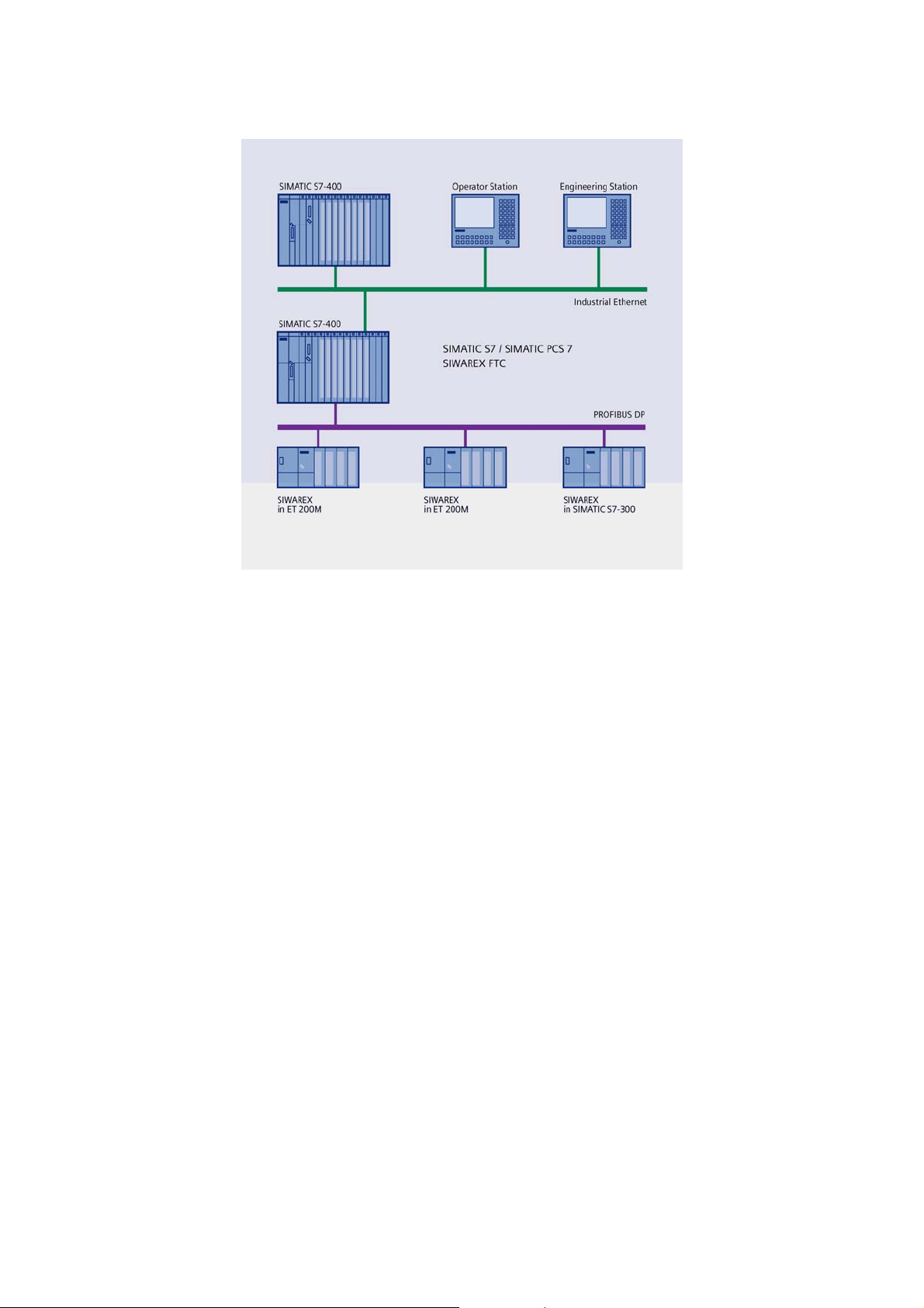
Figure 3-1 Configuration of SIMATIC S7/PCS7 with SIWAREX FTC
3.7 Commissioning and Service with SIWATOOL FTC_B
For commissioning and for service, there is a special program - SIWATOOL
FTC_B for belt scales and Windows operating systems.
The program enables commissioning of the scale without having to understand
automation technology. During a service procedures, you can analyze the
processes in the scale and test them with the help of a PC. Reading the
diagnostics buffer from the SIWAREX FTC is very helpful in analyzing events.
Besides complete access to all parameters, memory or print-outs of the weighing
file, the program can create weighing curves as well.
3-8 SIWAREX FTC
Page 21
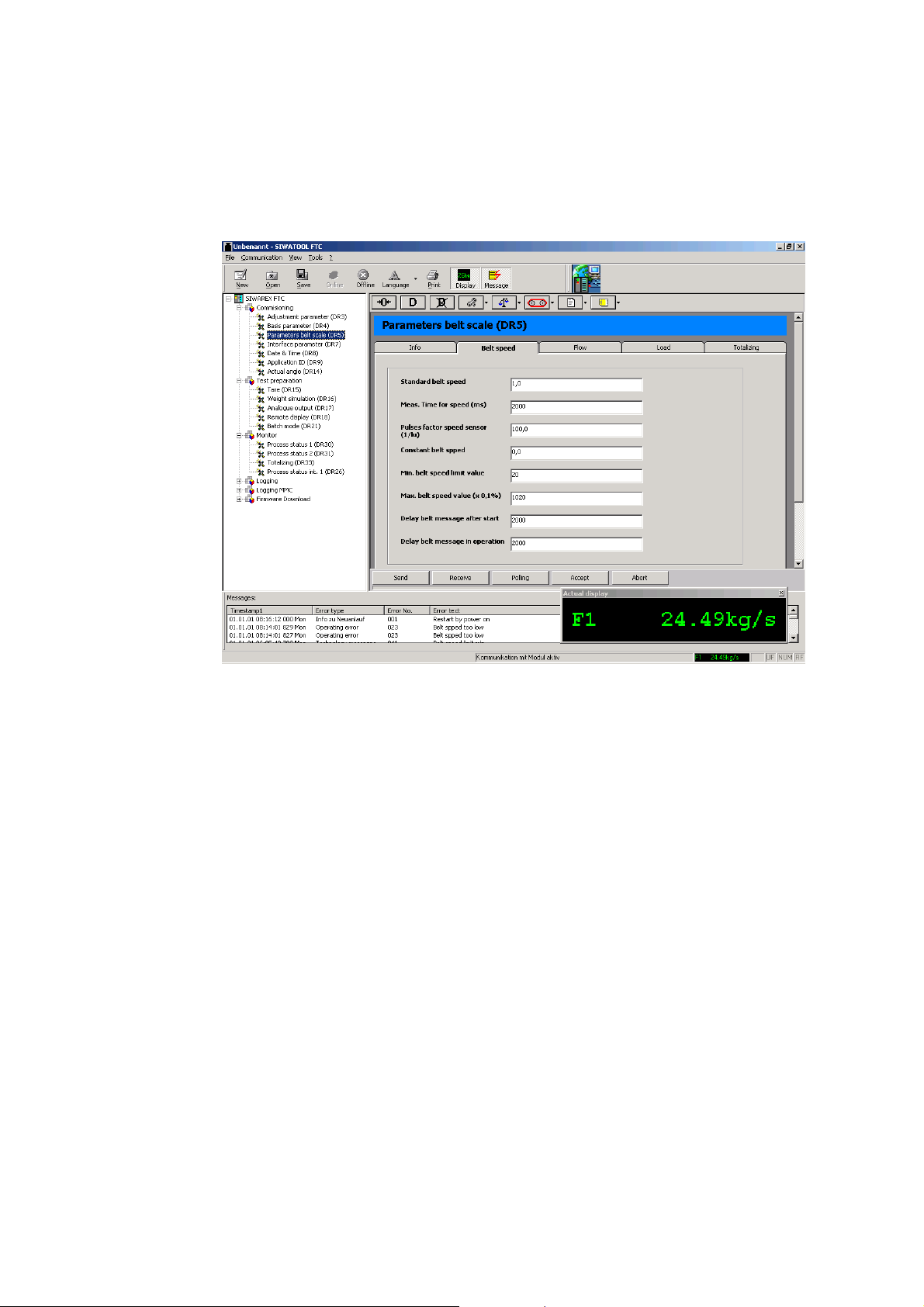
PRODUCT OVERVIEW
SIWATOOL
the calibratable scale memory.
The following figure shows the structure of the individual program windows.
FTC_B can also be used for reading the contents of the records from
Figure 3-2
SIWATOOL FTC_B Overview
SIWATOOL FTC_B does not only support the user in entering parameters. It is
very useful to analyze the diagnostic buffer, the contents of which can be saved
along with the parameters after reading from the module.
A trace mode exists in the SIWAREX FTC module for optimizing weighing
progress. The recorded data can be displayed in a curve diagram using MS Excel.
These records can then be used to e.g. analyze and optimize the material flow for
a shift.
3.8 Firmware Download with SIWATOOL FTC_B
Another feature of the SIWATOOL FTC_B program helps in loading a new version
of firmware onto the SIWAREX FTC, on-site. It allows upgrades or function
expansions for the firmware at any time and from anywhere.
3.9 Reading the Stored Weighing Logs with SIWATOOL FTC_B
The weighing logs are stored on an MMC (Micro Memory Card) that can be
inserted into the SIWAREX FTC. If a person disagrees with the results of a certain
weighing procedure, the weighing data for that weighing procedure can be
reconstructed from the MMC memory.
SIWAREX FTC
3-9
Page 22

4 Hardware Configuration and Assembly
!
Warning Notes
This chapter contains information required for hardware planning, assembly and
preparations for operation.
The technical safety information is to be strictly adhered to.
!
Warning
Unqualified intervention in the device/system or not adhering to the warning notices
can result in serious injury or damage to equipment. Only qualified personnel are
permitted to access the operational components of this device / system.
!
Warning
The unit has been developed, manufactured, tested and documented in
accordance with the corresponding safety standards. The device itself will not
cause any danger to equipment or personal health under normal circumstances.
!
Danger
Commissioning is not permitted until it is guaranteed that the machine in which
these components are to be integrated meets with the guidelines in 89/392/EWG.
4-10 SIWAREX FTC
Page 23

HARDWARE CONFIGURATION AND ASSEMBLY
4.1 Configuring the Hardware in SIMATIC
SIWAREX FTC is a function module (FM) in the SIMATIC S7 300 automation
system. It can be installed in any position designated for function modules.
Utilization with the SIMATIC S7 300 is possible in central operation, in an
expansion device or decentralized in the ET 200M system.
Operation with the SIMATIC S7 400 is only possible decentralized in the ET 200M
system. In this case, the active back-plane bus can be used.
In estimating the maximum number of SIWAREX FTC's that can be integrated
within one system, the following information may be helpful.
Total width Current requirements
(5V) from SIMATIC backplane bus
n x 80 mm n x 50 mA 4100 Bytes + n x 1200
Table 4-1 Requirements for n SIWAREX FTC modules
Max. amount in central operation – 8 SIWAREX FTC
Max. amount with multi-line expansion – 8 SIWAREX FTC per line
Max. amount in system ET 200M – 7 SIWAREX FTC per station
Selecting the suitable SIMATIC CPU, the SIMATIC HMI (Human Machine
Interface) and the communication modules does not only depend on
SIWAREX FTC requirements but also on the overall job that the automation
system has to perform.
4.2 Structure to EMC Guidelines
SIWAREX FTC is a highly accurate measuring device that has to dependably
measure the slightest signal. Proper assembly and wiring are therefore absolutely
essential for fault-free operation.
RAM requirements in
SIMATIC CPU
Bytes
4.2.1 Definition: EMC
EMC (Ele
function without faults in a defined electromagnetic environment without being
influenced by its surroundings and without negatively influencing the surroundings.
4.2.2 Introduction
Although SIWAREX FTC was devel
meets high EMC specifications, you should carry out EMC planning before
installing your controller to determine and take into account any possible
interference sources.
SIWAREX FTC
ctromagnetic Compatibility) describes the ability of an electrical device to
4-11
oped for use in industrial environments and
Page 24

4.2.3 Possible Effects of Interference
Electromagnetic interference can influence the automation system and the
SIWAREX FTC in various ways:
- Electromagnetic fields that have a direct influence on the system
- Interference that infiltrates the environment through bus signals
(PROFIBUS DP etc.)
- Interference through process cabling (e.g. measurement lines)
- Interference infiltrating the system through the power supply and/or protective
ground
Interference can impair the fault-free functioning of the SIWAREX CF.
4.2.4 Coupling Mechanisms
Dep
ending on the means of distribution (conductive or non-conductive bound) and
the distance between the interference source and the device, interference can be
introduced into the automation system through four different coupling mechanisms.
Galvanic coupling
Capacitive coupling
Inductive coupling
Radiation coupling
4.2.5 Five Basic Rules for Guaranteeing EMC
If you follow these five basic rules, EMC can be guaranteed in most cases!
Rule 1: Large surface area grounding connection
Ensure that while installing the automation devices, a well-made large surface area
ground connection is made between the inactive metal components (see following
sections).
Connect all inactive metal components and low-impedance components with
ground (broad cross-section).
Use screwed connections on painted or anodized metal surfaces either with
special contact washers or remove the insulated protective surface at the contact
points.
Do not use aluminum components for ground connections if at all possible.
Aluminum oxidizes easily and is therefore less suitable for grounding connections.
Find a central location for connections between the grounding point and the ground
wiring system.
4-12 SIWAREX FTC
Page 25

HARDWARE CONFIGURATION AND ASSEMBLY
Rule 2: Prop
Separate the cabling into groups (high-voltage lines, power supply lines, signal
lines, ground wiring, data lines etc.).
Run the high-voltage lines and ground wiring or data cables in separate channels
or bundles.
Run measurement lines as close to grounding surfaces as possible (e.g. support
beams, metal rails, cabinet panels).
Rule 3: Fixed cable shielding
Ensure that the cable shielding is connected properly.
Use shielded data lines only. The shielding must be fastened to ground using a
large surface area on both ends.
The shielding of measurement lines must be fastened to ground on both ends.
Run cable shielding directly under the SIWAREX FTC on the shielding channeling.
The shielding is to be run to the connection terminal.
The connection between the shielding rail / ground rail and the cabinet /housing
must be low impedance.
Use metallic or metal-plated connector housings for the shielded data lines.
er wiring
Rule 4: Special EMC measures
All inductivity that is to be controlled should be connected with suppressors.
Use interference suppressed fluorescent lighting or incandescent lamps for
illuminating cabinets or housings in the immediate vicinity of your controller.
Rule 5: Uniform reference potential
Create a uniform reference potential and ground all electrical operational elements.
If potential differences arise or can be expected between components of your
system, install adequately dimensioned potential equalizing lines. For applications
in areas with a risk of explosion, potential equalization is mandatory.
4.3 Assembly on the Profile Rail
When assembling the SIMATIC components and the SIWAREX FTC, the assembly
regulations must be completely fulfilled for the SIMATIC S7.
SIWAREX FTC is assembled in the following steps:
1. Check for whether the SIMATIC bus connector is connected to the left of the
SIWAREX FTC in the module group.
SIWAREX FTC
4-13
Page 26
2. Connect the SIMATIC bus connector for the following module group in the
SIWAREX if necessary.
3. Install the shielding strip under SIWAREX.
4. Hang the SIWAREX FTC in its place.
5. Fasten the SIWAREX FTC with 2 screws in the lower area of the module.
6. Label the SIWAREX FTC corresponding with your identification system.
4.4 Connection and Wiring
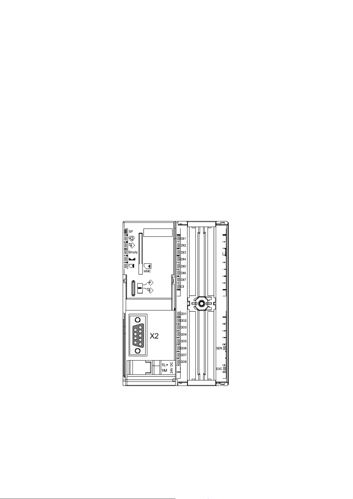
4.4.1 Connection Areas for SIWAREX FTC
The followi
- Screw-in connector for 24 V power supply
- 40 pin connector for load cell connection, digital input and output, RS 485,
- 9 pin D-sub socket for RS 232 to PC or printer connection
ng connection areas are found on the front:
analogue output, counter input
Figure 4-1
4-14 SIWAREX FTC
SIWAREX FTC front view
Page 27
HARDWARE CONFIGURATION AND ASSEMBLY
Shielding Connection
4.4.2
Special attent
The interference resistance of the system can only be guaranteed if the properly
constructed.
A cable is shielded to decrease the affects of magnetic, electrical and
electromagnetic interference on this line. Interference on cable shielding is routed
to ground through shielding rails that are conductively connected with the housing.
To ensure that this interference does not become a source of interference, a low
impedance connection to ground is especially important.
Use only lines with mesh-shielding. The shielding should provide at least 80%
coverage.
For fastening the meshed shielding, use only metal cable clamps. The clamps
must cover as much shielding as possible and ensure a good contact.
Shield clamps must be ordered separately from the grounding elements. The area
covered by the shielding clamp is to be chosen corresponding with the cable
diameter.
Approximately 1.5 cm of the cable insulation must be exposed in the area of the
cable to be fastened to the shielding clamp. The exposed shielding is then pressed
firmly against the grounding element with the shielding clamp.
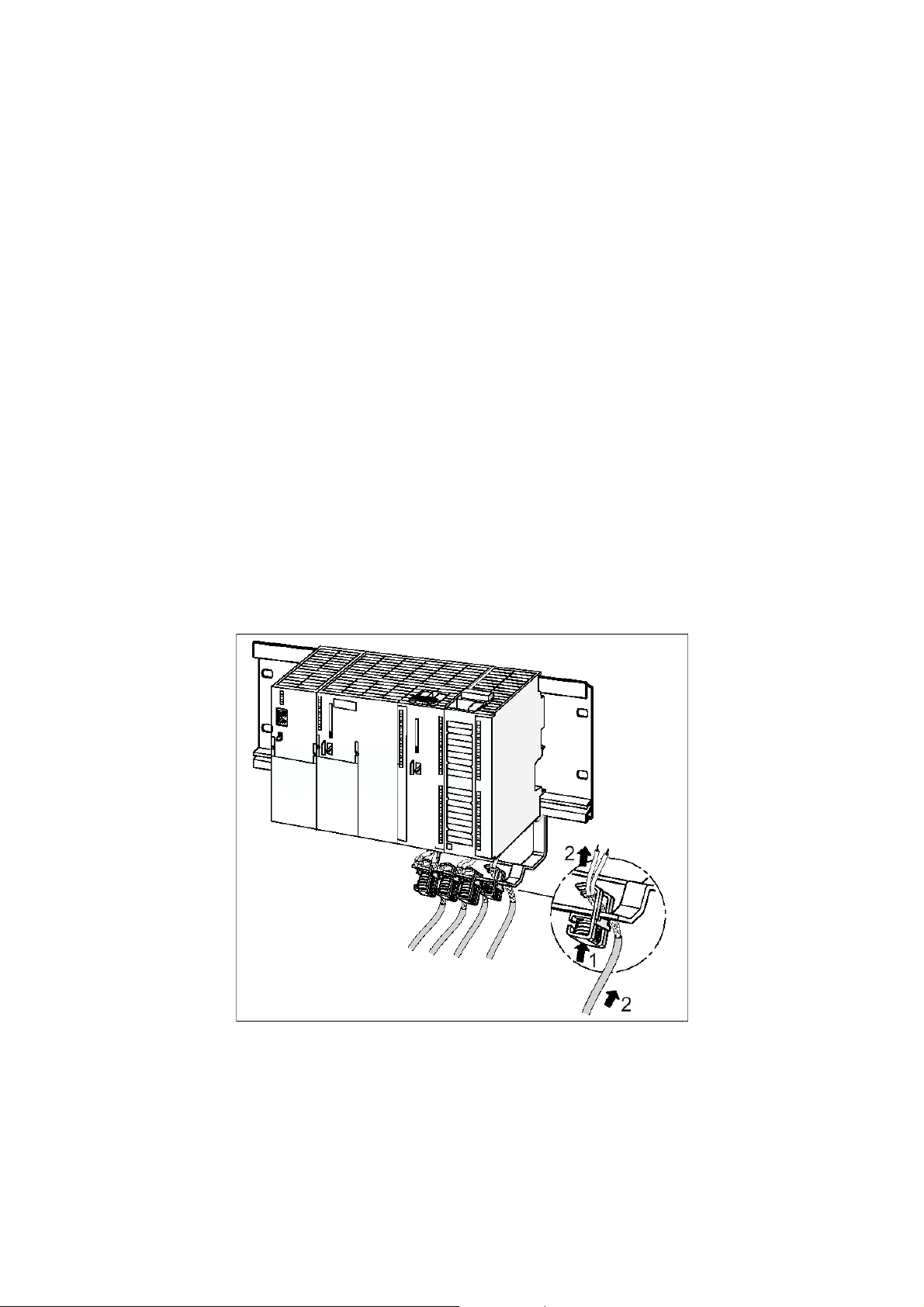
The following figure shows the assembly of the shield clamps.
ion must be given to the shield strip for the shielded lines.
Figure 4-2 Shield clamp assembly
The shielding should be pressed against the shielding rail by the shielding clamp.
SIWAREX FTC
4-15
Page 28

4.4.3 Connection of 24 V Power Supply
T
he 24 V supply voltage is connected with a screw connector. The connection is found
in the lower area of the module groups next to the D-sub connector for RS 232.
Note
In the S7 300 or ET200M system, the SIMATIC CPU or IM 153 and SIWAREX FTC
must be connected to the same 24 V supply.
Termination Clamp Signal Comment
1L+ 24 V DC 1L+ Power supply +
1M 24 V DC 1M Power supply M
Table 4-2 Power supply connection
4.4.4 Connections to Front Terminal
The SIMATIC con
struction guidelines apply for connecting the 40 pin connector.
Flexible cables with a cross-section of 0.25 to 1.5 mm
insulation from the cable for 6 mm and install wire end sleeves.
4.4.5 Load Cell Connection
rs equipped with strain gauges and that meet the following conditions can be
Senso
connected to the SIWAREX FTC:
- Characteristic value 1.... 4 mV/V
- Supply voltage of 10.2 V is permitted
The connection is made to the 40 pin front connector. The connection should be
made using the cable described in chapter
Termination
Clamp
Signal Comment
X1.34 AGND
2
can be used. Remove the
Accessories.
Analogue ground (is normally not connected,
on where required, e.g. with additional load
cell power requirement)
X1.35 SEN+ Sensor line +
X1.36 SEN- Sensor line -
4-16 SIWAREX FTC
Page 29

HARDWARE CONFIGURATION AND ASSEMBLY
Termination
p
Clam
Signal Comment
X1.37 SIG+ Measurement line +
X1.38 SIG- Measurement line -
X1.39 EXC+ Load cell supply voltage +
X1.40 EXC- Load cell supply voltage -
Table 4-3 Load cell connections
The following rules are to be followed when connecting load cells (WZ).
Using a junction box is required if more than one LC is connected (the LC must be
connected parallel to one-another).
If the distance from the LC to the SIWAREX FTC is greater than the existing length
of the LC connection cable, then the extension box EB is to be used.
2. The cable shielding is normally run on the cable guide supports of the junction box.
In case of the danger of potential equalization currents on the cable shielding,
a potential equalization conductor is to be run parallel to the load cell cable or the
shield clamp is to be used in the junction box to the shield strip. Using the potential
equalization conductor is the preferred method of dealing with EMC
(Electromagnetic Compatibility).
3. Twisted pair cable is required for the indicated wiring:
- Sensor lines (+) and (-)
- Measurement voltage lines (+) and (-)
- Supply voltage lines (+) and (-)
4. The shielding is to be attached to the shielding strip on the SIWAREX FTC.
The two figures below show the load cell connection using 4-wire and 6-wire
systems.
SIWAREX FTC
4-17
Page 30
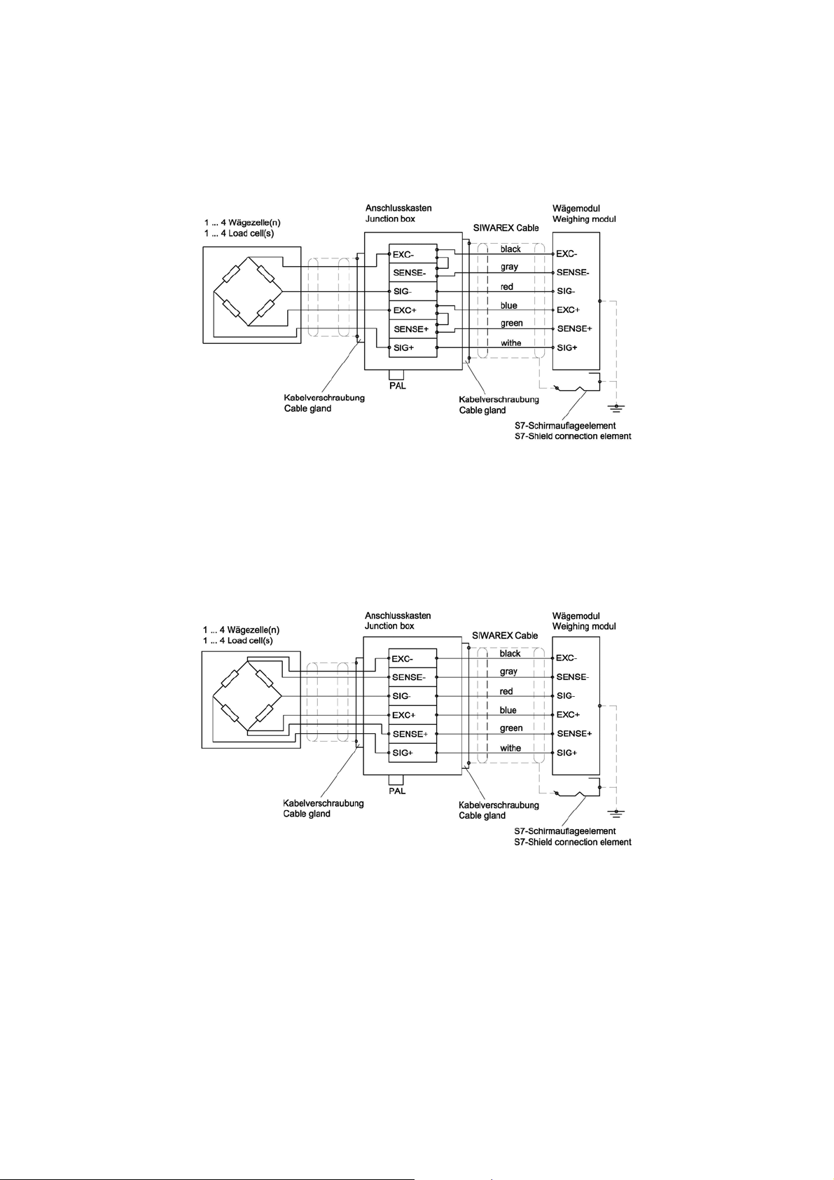
Figure 4-3 Load cell connection in 4-wire system
Figure 4-4 Load cell connection in 6-wire system
4.4.6 Digital Inputs
SIWAREX FTC ha
module group. They have a common reference point (M).
4-18 SIWAREX FTC
s 7 digital inputs. These inputs are potentially isolated from the
Page 31
HARDWARE CONFIGURATION AND ASSEMBLY
The fun
DI status is indicated with and LED on the front of the SIWAREX FTC.
The inputs may only be activated if your functional allocation is known and the
activation will not cause any harm.
Termination Clamp Signal Comment
ctionality of each input can be defined with parameters.
!
Warning
X1.1 DI 1 Parameter definable function
X1.2 DI 2 Parameter definable function
X1.3 DI 3 Parameter definable function
X1.4 DI 4 Parameter definable function
X1.5 DI 5 Parameter definable function
1.6 DI 6 Parameter definable function
X1.7 DI 7 Parameter definable function
X1.8 2M Reference ground for digital inputs
Table 4-4 Digital input connections
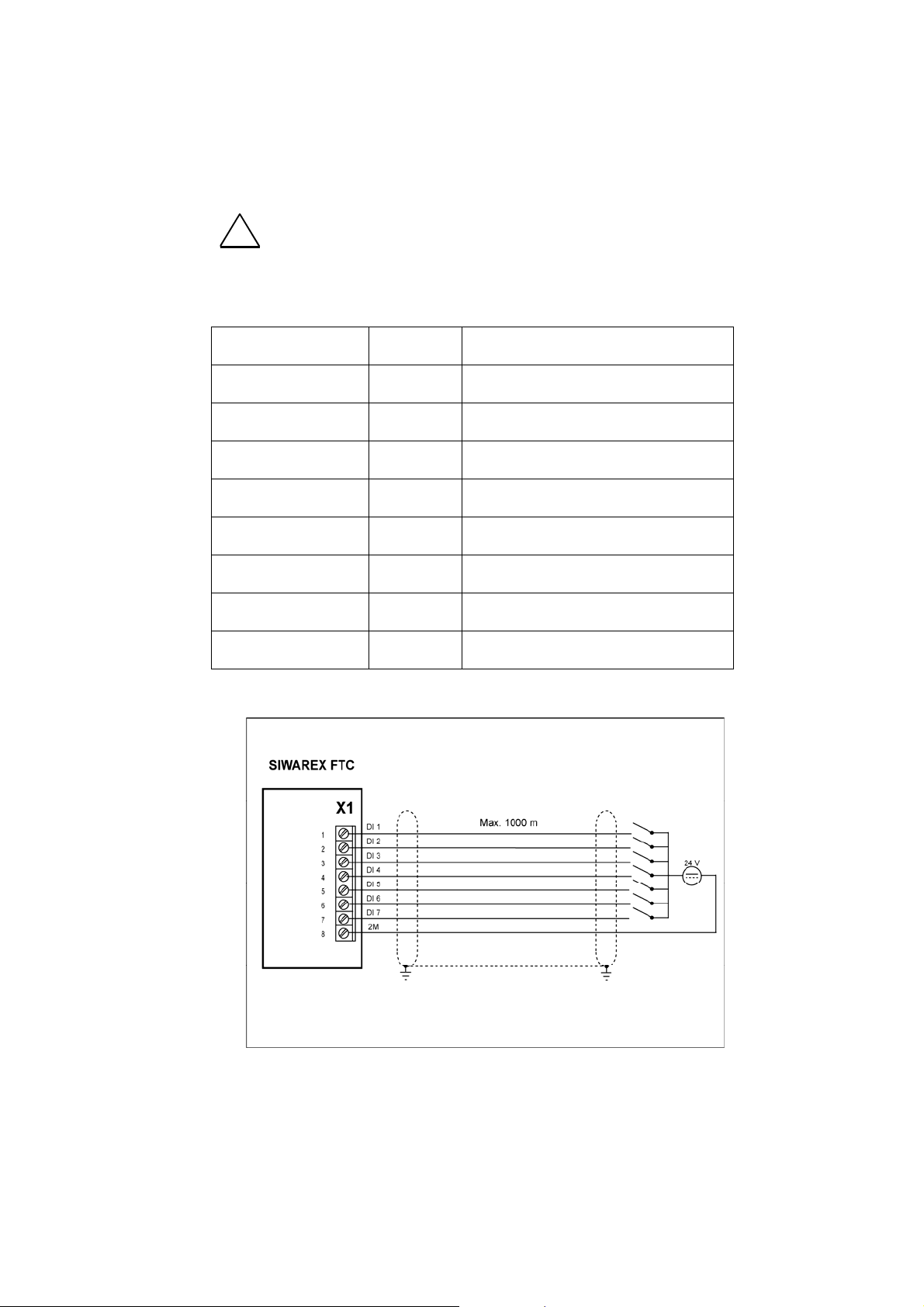
Figure 4-5
Digital inputs
SIWAREX FTC
4-19
Page 32
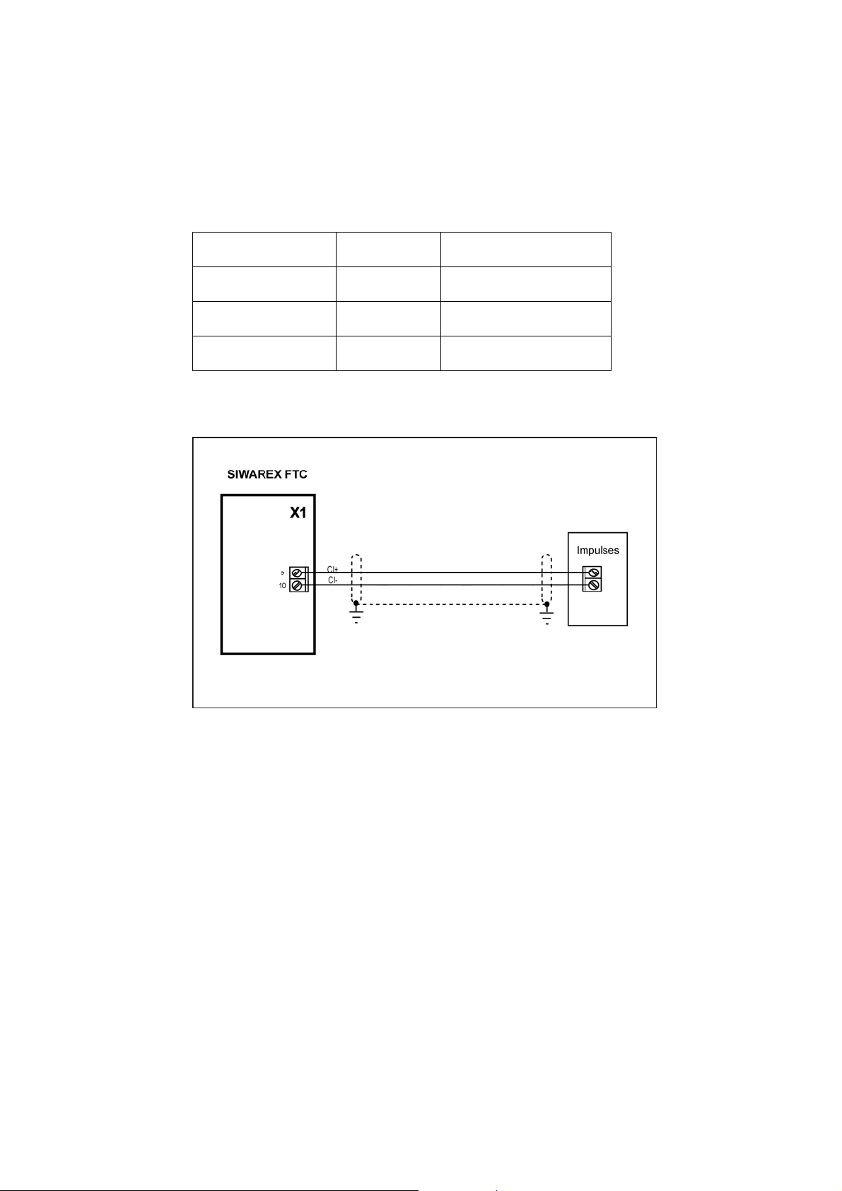
4.4.7 Counter Input
The counter input serves for connecting a pulse encoder which is required when
using a belt scale in continuous operation. Twisted pair wiring should be used for
the connections.
Termination Clamp Signal Comment
X1.9 CI+ Counter input +
X1.10 CI- Counter input -
Table 4-5 Pulse encoder connection
Figure 4-6
4.4.8 Digital Outputs
Counter input
The SIWARE
voltage of + 24 V and an output current of maximum 0.5 A per output (max. total
current 2 A).
These outputs are potentially isolated from the module group. The outputs share
common potential. They have a common ground and a secure 24 V supply.
They are short-circuit and overload protected.
DO status is indicated with and LED on the front of the SIWAREX FTC.
When connecting inductive consumers, the digital output that is used must be
equipped with a free-wheeling diode.
X FTC has eight potential isolated outputs (DO) with a nominal
4-20 SIWAREX FTC
Page 33
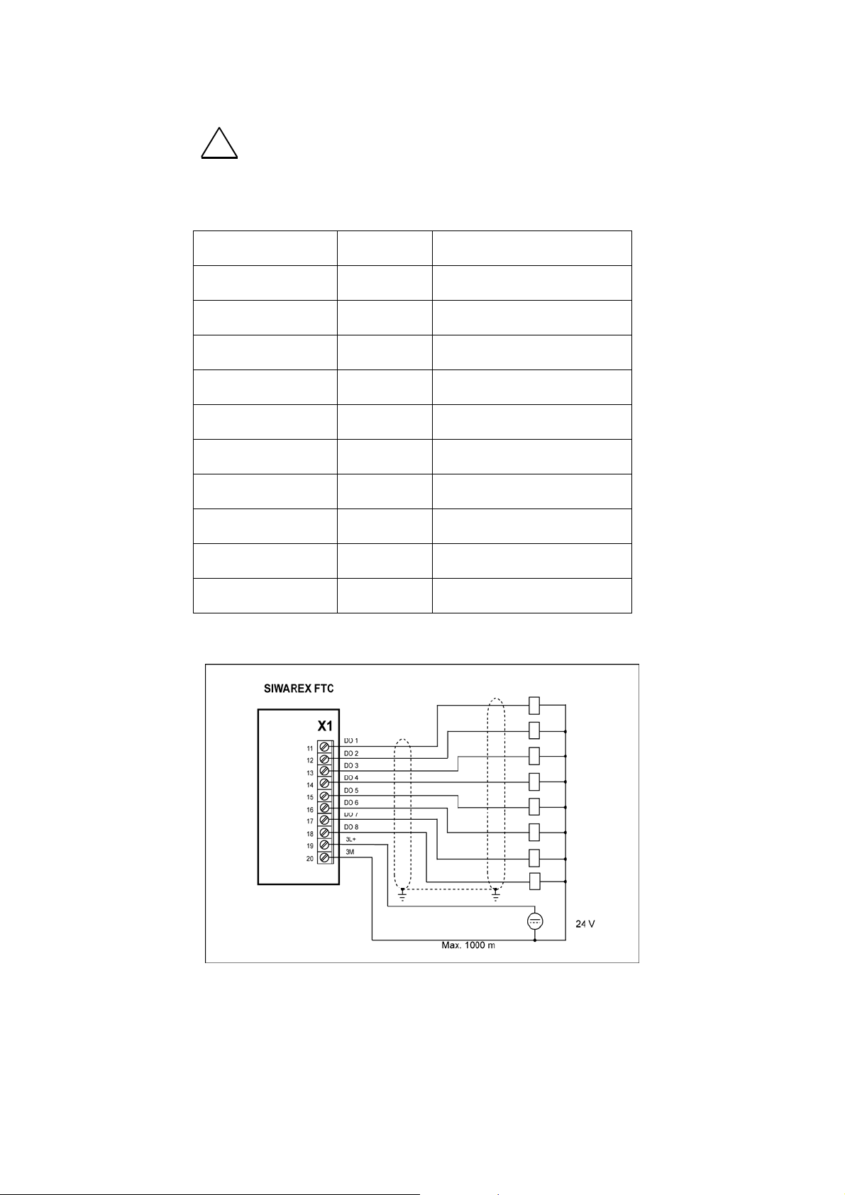
HARDWARE CONFIGURATION AND ASSEMBLY
!
The outputs may only be activated if their functional allocation is known and the
activation will not cause any harm.
Termination Clamp Signal Comment
Warning
X1.11 DO 1 Parameter definable function
X1.12 DO 2 Parameter definable function
X1.13 DO 3 Parameter definable function
X1.14 DO 4 Parameter definable function
X1.15 DO 5 Parameter definable function
X1.16 DO 6 Parameter definable function
X1.17 DO 7 Parameter definable function
X1.18 DO 8 Parameter definable function
X1.19 3L+ 24 V for digital outputs
X1.20 3M Ground for digital outputs
Table 4-6 Digital output connections
Figure 4-7
Digital outputs
SIWAREX FTC
4-21
Page 34
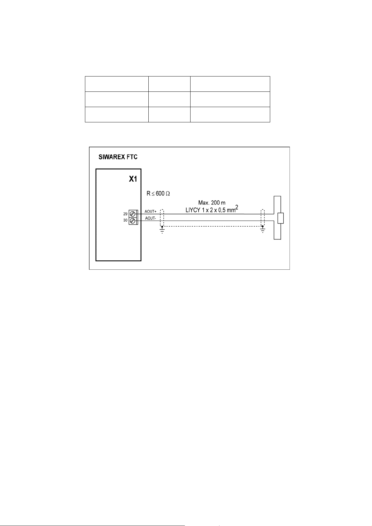
4.4.9 Analog output
Termination Clamp
X1.29 IOUT+ Analogue output +
X1.30 IOUT- Analogue output -
Table 4-7 Analog output connection
Signal Comment
Figure 4-8
4.4.10 Interface RS 485 for Mettler Toledo type WM or WMH
Analog output
Digital sensors from the Mettler Toledo company of type WM or WMH can
be connected to Siwarex. The following interface parameters (data record 3
and 7) are to be set:
(DR3) Device selection: Digital load cell Mettler Toledo
(DR7) Baudrate: 38400
(DR7) Character parity: even
(DR7) Data bits: 7
(DR7) Stop bits: 1
4-22 SIWAREX FTC
Page 35
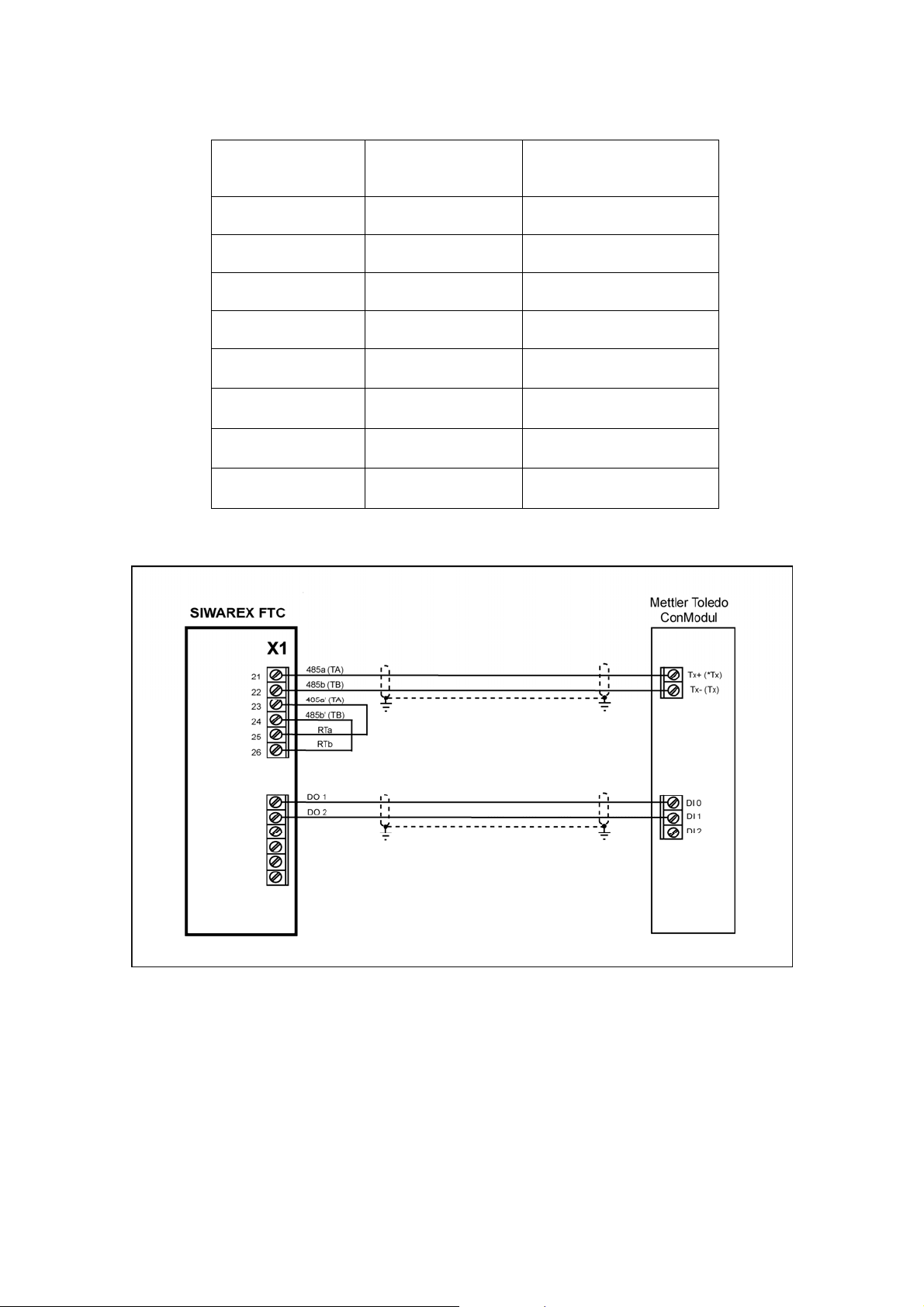
HARDWARE CONFIGURATION AND ASSEMBLY
Termination
Clamp
X1.21 485a
X1.22 485b
X1.23 485a
X1.24 485a
X1.25 RTa
X1.26 RTb
X1.11 DO 1
X1.12 DO 2
Table 4-8 RS 485 Connections
Signal Comment
Input Ta
Input Tb
Output Ta
Output Tb
Termination resistor
RTa
Termination resistor
RTb
Send Start instruction
(sir)
Send Stop instruction
(si)
Figure 4-9
Connecting METTLER TOLEDO type WM or WMH some additional
parameters must be set.
SIWAREX FTC
Connecting Mettler Toledo type WM or WMH to RS 485
4-23
Page 36
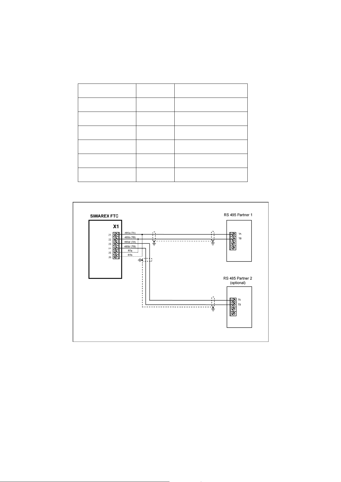
4.4.11 RS 485 Interface
Termination Clamp
X1.21 485a Input Ta
X1.22 485b Input Tb
X1.23 485a Output Ta
X1.24 485a Output Tb
X1.25 RTa Termination resistor RTa
X1.26 RTb Termination resistor RTb
Table 4-9 RS 485 connection
Signal Comment
Figure 4-1
4.4.12 Connecting the Remote Display from Siebert
4-24 SIWAREX FTC
0 RS 485 connection
One or m
The displays can only be used for displaying weights in "Non automatic weighing
instrument" operating mode.
ore Siebert Type S102 displays can be connected to the RS485 interface.
Page 37
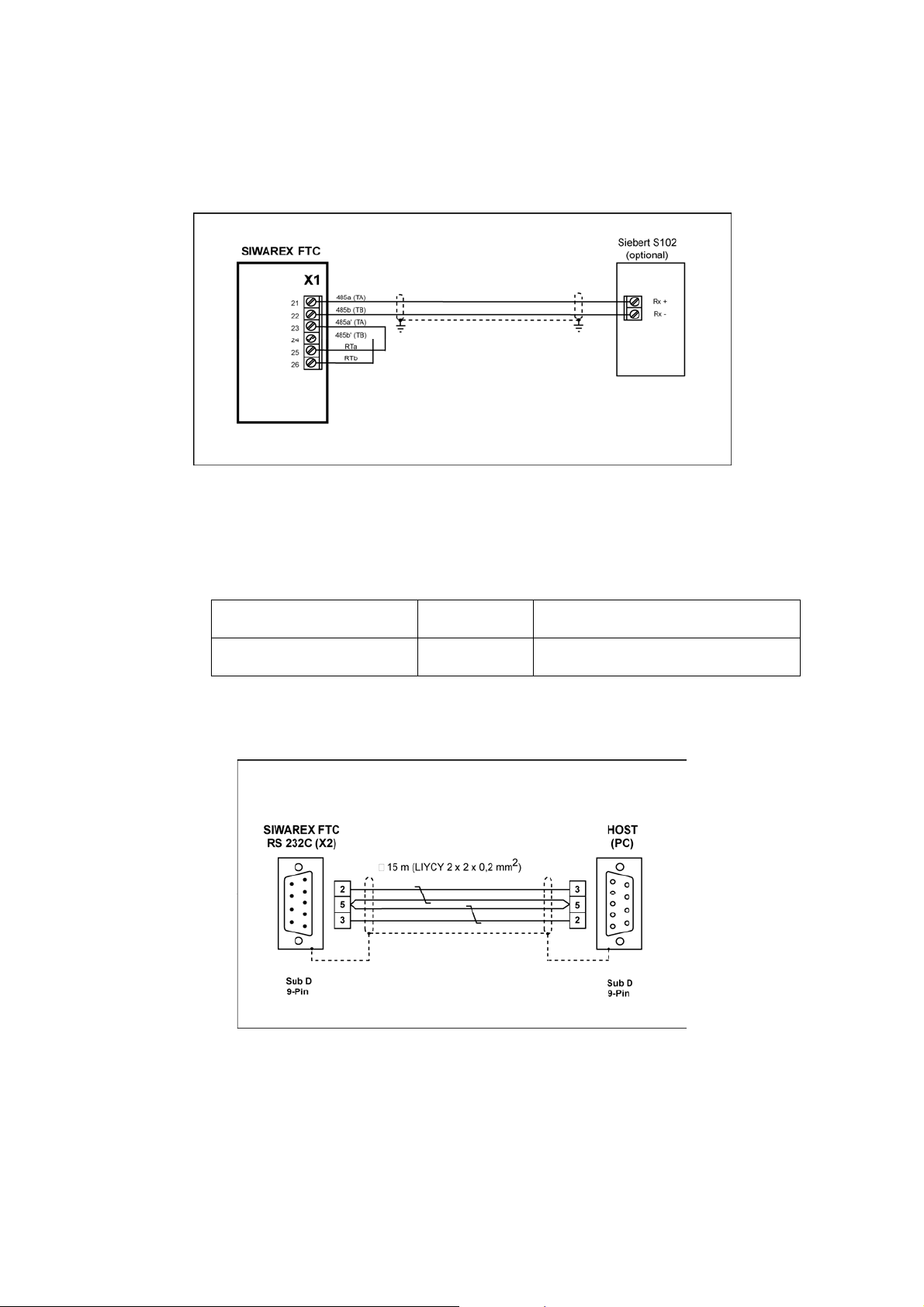
HARDWARE CONFIGURATION AND ASSEMBLY
n connecting a single display, ensure that the RTa and RTb bridges are wired.
Whe
When installing the S102 for operation, the same parameters that have been set by
the SIWATOOL FTC for RS 485 are to be defined.
Figure 4-1
1 Connecting the S102 display
4.4.13 Connecting the PC for SIWATOOL FTC
Table
Termination Clamp Signal Comment
X2 9 pin D-type RS 232 Interface
Table 4-10 Connecting the PC
Ready-made cables are available for connecting the PC (see
RS 232 Interface
Accessories)
Figure 4-1
SIWAREX FTC
2 Connecting the PC
4-25
Page 38

4.4.14 LED Display Elements
Label LED color LED Description
SF Red LED 1 upper
left
Green LED 2
Green LED 4
Green LED 6
EXC Green LED 7
SEN Green LED 8
Table 4-11 Display Elements (LED)
Green LED 3
Green LED 5
System Fault
Hardware fault
Continuous operation active
(flashing)
Write protect for calibration data
activated
Scale in empty range
Scale at stand-still
Micro Memory Card is operation
ready
Load cell supply
Supply voltage feedback from
load cells
4.4.15 Using the Micro Memory Card
Only a SIMATIC Micro Memory Card ca
records or for recording weighing states. Approximately 16 MB of data can be
stored with the MMC described in chapter
!
Warning notice
After formatting the MMC with SIWAREX FTC, it can no longer be used in the
SIMATIC-CPU! Therefore, the MMC should be labeled correspondingly.
n be used for saving the calibratable
Accessories.
4-26 SIWAREX FTC
Page 39

HARDWARE CONFIGURATION AND ASSEMBLY
4.5 Preparing for Operation
Introduction
Visual check
24 V to
SIWAREX FTC
connection
LED checks on the
SIWAREX FTC
After assembling the module group and making all connections, the next part
of the commissioning process is to perform a partial functionality check on the
SIWAREX FTC and all connected components.
The individual steps for partial testing are to be performed in the following
sequence:
Check all previously performed steps for proper execution, i.e.:
• Is there any external damage to the module group?
• Are the modules situated in the proper positions?
• Are all fastening screws properly tightened?
• Are all connecting cables properly connected and fastened tightly?
• Is the frontal connection made properly?
• Is the shielding properly attached to the shielding conductor for all
corresponding cables?
• Is the profile rail connected to the ground conductor?
• Have all tools, materials or components that do not belong to the S7 or
SIWAREX FTC been removed from the profile rail and the module group?
Turn on power supply on.
Proper initialization of the SIWAREX FTC in the SIMATIC can only be
guaranteed if:
- the S7-CPU (with decentralized connection with IM 153-1) and the
SIWAREX FTC are switched on at the same time
or
- the SIWAREX FTC first.
After applying the 24V supply voltage and a short initialization phase (internal
tests are indicated by LED running sequence), the SIWAREX FTC goes into
operating status. The following LEDs must have the status that is indicated
below if the unit is running correctly:
LED (EXC) --> ON status
LED (SEN) --> ON status
LED (SF) --> OFF status
SIWAREX FTC
4-27
Page 40

4.6 Application in Ex-Zones
!
D A N G E R E X P L O S I O N
Exists when the installation and setup regulations are not adhered to.
Danger
!
For using the SIWAREX FTC in areas with a risk of explosion, the important
information in the “SIMATIC Automation Systems - Basics of Explosion
protection (Doc.No. A5E00206200)” must be observed!
Below you will find important information on the installation of the
SIWAREX FTC in a hazardous area.
SIWAREX FTC may only be used under the conditions, which are specified
in the appropriate certificates.
The SIWAREX FTC can be used in Ex zone 2 (acc. to IEC/CENELEC,
directive 94/9/EG).
In the following you find some details about the certificates ATEX (Europe)
and UL (USA, Canada).
Certificate: ATEX:
Type Examination Certificate Number: ATEX Nr. KEMA 08ATEX0002 X
Please always observe the relevant safety instructions. These
!
can be accessed on the Internet at
http://support.automation.siemens.com/WW/view/en/29443327
4-28 SIWAREX FTC
Page 41

HARDWARE CONFIGURATION AND ASSEMBLY
Certificate: c-UL-us haz. loc.
UL file number. USA: NRAG.E239877
UL file number Canada: NRAG7.E239877
Note to c-UL-us haz.loc:
Warning – Explosion Hazard – Do not disconnect while circuit is live unless
area is known to be non-hazardous.
Warning – Explosion Hazard – Substitution of components may impair
suitability for Class I, Division 2.
This equipment is suitable for use in Class I, Division 2, Groups A, B, C, D
or non-hazardous locations only.
Connection from load cells to SIWAREX FTC:
The SIWAREX FTC can be connected with load cells in zone 1 or zone 2.
For a connection of load cells in zone 2 it is sufficient, that the load cells
also have an approval for zone 2 and all associated directives as well as
the installation instructions are respected.
For a connection of load cells in zone 1, load cells with the adequate
approvals are needed and appropriate provisions according to the
guidelines must ensure explosion protected operation. For example
SIWAREX R load cells can be connected intrinsically safe via the ExInterface SIWAREX IS. The instructions for the Ex-Interface, the load cells
and the ATEX as well as the c-UL-CSA directives have to be respected.
Installation and Maintenance:
Required connection and installation work must be performed by qualified
personnel.
Repairs can only be carried out at the production location.
SIWAREX FTC
4-29
Page 42
5 Weighing Functions and Parameters
5.1 General
The SIWAREX FTC can be used as a Non Automatic Weighing Instrument, for
force measurement, belt scale, loss-in-weight scale or as bulk flow measurement
device. The operating mode is set once when commissioning the scale in the
adjustment data area (data record 3).
The selected operating mode and the defined parameters are very important to the
behavior of the SIWAREX FTC in the process.
The parameters are set with default values from the manufacturer. Using the
command "Load default values", the parameters defined in the factory are set
again.
The default operating mode is "Belt scale". If you want to run the scale in
another operating mode (e.g. loss-in-weight scale), you have to set the
operating mode during commissioning (e.g. to "Loss-in-weight scale").
The default parameters are defined so that the scale is immediately ready for each
operating mode. Not all parameters must be re-entered for each operating mode.
By changing a parameter, the behavior of the scale is changed respectively.
The advantage of this solution is that you can define how many of the default
values should be retained and how much the behavior of the scale has to be
adapted for the application.
All parameters are split into data records (DR) . The data records are organized
according to process steps (tasks) that you have to perform during the
commissioning phase or during the process itself.
An overview of data records is provided in the following table.
DR
Content / Structure Comment Cross-
No.
3 Adjustment parameter All operating modes
4 Basic parameter All operating modes
5 Belt scale Belt scale (separate manual)
55 Bulk flow measurement device Bulk flow measurement device
6 Differential scale 1 Loss-in-weight scale
7 Interface parameters All operating modes
8 Date / Time All operating modes
9 Application ID All operating modes
10 Differential scale 2 Loss-in-weight scale
reference
5.2
5.4
5.5
5.6
5.7
5.8
5-30 SIWAREX FTC
Page 43

WEIGHING FUNCTIONS AND PARAMETERS
DR Content / Structure Comment CrossNo. reference
11 Device characteristic curve Loss-in-weight scale
12 PID controller parameter Loss-in-weight scale
13 Material characteristic curve Loss-in-weight scale
14 Current tilt angle Only belt scale (separate manual)
15 Tare input NAWI, Force, Belt scale
16 Weight simulation value All operating modes
17 Ext. analog default value All operating modes
18 Ext. display default value All operating modes
20 Target_flow_value Loss-in-weight scale
21 Parameter for batch operation Belt scale (separate manual)
26 Internal state All operating modes
30 Process state 1 NAWI, Force measurement, Belt scale
31 Process state 2 All operating modes
32 Process value differential scale Loss-in-weight scale, bulk flow
33 Totals Belt scale, loss-in-weight scale, bulk
34 ASCII weight value All operating modes
35 Cryptodata All operating modes
36 Process values PID-controller Loss-in-weight scale
37 Quality Loss-in-weight scale
40 Log text 1 All operating modes
41 Log text 2 All operating modes
42 Log text 3 All operating modes
43 Log text 4 All operating modes
44 Last log data All operating modes
45 String All operating modes
46 Log ID for requirements through
S7 interface
47 Log output to S7 interface All operating modes
120 MMC-trace data All operating modes
121 RAM-trace data All operating modes
122 MMC-log data All operating modes
123 MMC/RAM-Trace-/Log- process
values
measurement device
flow measurement device
All operating modes
All operating modes
5.10
5.11
5.12
5.13
5.14
5.15
5.16
5.17
5.18
5.19
5.20
5.20
5.20
5.20
5.21
5.22
5.23
5.24
5.25
5.25
5.27
5.26
Table 5-1 Data record overview
In the following parameter description, you will find a description of the weighing
functions that are influenced by that parameter.
The parameters of a data record are shown in a table to start with.
This is then followed by the exact parameter description for the parameters of that
data record. After the receipt of new parameters, SIWAREX FTC performs a
SIWAREX FTC
5-31
Page 44

plausibility test corresponding with the defined operating mode. If there is a
parameter error then the data record will not be accepted (stored) by the
SIWAREX FTC and a "synchronous" message is generated (see chapter
Messages and Diagnosis
).
5.2 DR3 Adjustment Parameters
The adjustment parameters must be checked for each new scale and must be
changed where necessary and most important, the operating mode must be
defined during commissioning.
The scale is basically defined using the adjustment parameter and by performing
the adjustment. Adjusting the scale can be done using adjustment weights
5.2.1) or theoretically (see 5.3). In verifiable operation as a non-automatic
(see
weighing machine, the data of the DR3 cannot be changed after calibration.
Procedures:
o Check all parameters and change if necessary
o Switch on service operation (command).
7
o Send the DR3 to the scale
o Perform scale adjustment
o Receive DR3 from the scale
o Switch off service operation
Name Type Address Default Range of Values / Meaning Reference
(6) Adjustment
Adjustment digits for
Adjustment zero 0
Adjustment digits for
Adjustment weight 1
Adjustment digits for
adjustment weight 2
Adjustment digits for
Adjustment weight 3
Adjustment digits for
Adjustment weight 4
Adjustment weight 1
(Flow rate with bulk flow
measurement device)
adjustment weight 2
(Flow rate with bulk flow
measurement device)
Adjustment weight 3
(Flow rate with bulk flow
measurement device)
Adjustment weight 4
(Flow rate with bulk flow
measurement device)
DINT DBD000 1398101 0 to: 224
DINT DBD004 15379113 0 to: 2
DINT DBD008 0 0 to: 224
DINT DBD012 0 0 to: 224
DINT DBD016 0 0 to: 224
REAL DBD020 50 > 0
REAL
DBD024 0 ≥ 0
REAL DBD028 0 ≥ 0
REAL
DBD032 0 ≥ 0
Other definitions not permitted.
24
Other definitions not permitted.
Other definitions not permitted.
Other definitions not permitted.
Other definitions not permitted.
Other definitions not permitted.
Other definitions not permitted.
Other definitions not permitted.
Other definitions not permitted.
5.2.1
5.2.1
5.2.1
5.2.1
5.2.1
5.2.1
5.2.1
5.2.1
5.2.1
5-32 SIWAREX FTC
Page 45

WEIGHING FUNCTIONS AND PARAMETERS
Name Type Address Default Range of Values / Meaning Reference
Characteristic value
range
(5) Filter
Filter sequence
Type of low pass filters BYTE DBB038 0 0: critically damped
Limit Frequency
Depth of
average value filter
(1) Adjustment parameter I 0
Scale Name
Number of weight ranges BYTE DBB056 1 1 Range
Scale type
Activate zero setting
upon start-up
Activated zero setting at
start-up, if scale is tared
Automatic zero
adjustment
BYTE DBB036 2 1: Characteristic value to 1mV/V
BYTE DBB037 0 Bit 0 :
BYTE DBB039 4 0: No filter
INT DBW040 10 [0 ... 250] x 10 ms
STRING
[10]
BYTE DBB057 0
DBB042 „SIWAREX
XX“
0
0
0
2: Characteristic value to 2mV/V
4: Characteristic value to 4mV/V
101: Characteristic value +/- 1mV/V (force
measurement, bi-directional)
102: Characteristic value +/- 2mV/V (force
measurement, bi-directional)
104: Characteristic value +/- 4mV/V (force
measurement, bi-directional)
Other definitions not permitted.
0: Average value filter before digital filter
1: Digital filter before average value filter
Bits 1 to 7 not set
1: Bessel filter
2: Butterworth filter
Other definitions not permitted.
1: fg = 20Hz
2: fg = 10Hz
3: fg = 5Hz
4: fg = 2Hz
5: fg = 1Hz
6: fg = 0.5Hz
7: fg = 0.2Hz
8: fg = 0.1Hz
9: fg = 0.05Hz
Other definitions not permitted.
0: Average value filter deactivated
Other definitions not permitted.
2 Ranges
3 Ranges
Other definitions not permitted.
Bit 0::
0: Multi-range scale
1: Multi-resolution scale
Bit 1:
0: Switch-on zero setting device switched off;
1: Switch-on zero setting device switched on
Bit 2:
0: Switch-on zero setting, not when tare 0
1: Switch-on zero setting performed with tare 0
Bit 3:
0: Zero tracking device switched off;
1: Zero tracking device switched on
Bit 4 - 7 not set
5.2.2
5.2.3
5.2.4
5.2.5
5.2.6
5.2.7
5.2.8
5.2.9
5.2.10
5.2.11
5.2.12
(2) Calibration parameter
II
Minimum weight for
Weighing range 1
REAL DBD058 1
5.2.13
SIWAREX FTC
5-33
Page 46

Name Type Address Default Range of Values / Meaning Reference
Maximum weight for
weighing range 1
Numeral step for
weighing range 1
Minimum weight for
Weighing range 2
Maximum weight for
weighing range 2
Numeral step for
weighing range 2
Minimum weight for
Weighing range 3
Maximum weight for
weighing range 3
Numeral step for
weighing range 3
(3) Calibration parameter
III
Standstill Time
Standstill Range
Wait time for standstill TIME DBD102 2000 If there is no standstill, the weighing command
Max. negative weight for
zero setting when
switching on
Max. positive weight for
zero setting when
switching on
Maximum negative
weight for zero setting
Maximum positive weight
for zero setting
Tare max. weight T-
REAL DBD062 100
REAL DBD066 0,02 Number step weighing range 1 (1*10 k, 2*10k,
REAL DBD070 0
REAL DBD074 0
REAL DBD078 0
REAL DBD082 0
REAL DBD086 0
REAL DBD090 0
TIME DBD094 1000 ms
REAL DBD098 0,02 Standstill range in weight unit
BYTE DBB106 10 Neg. Range of the switch-on zero setting device
BYTE DBB107 10 Pos. range for switch-on zero setting device [in
BYTE DBB108 1 Neg. Range of zero setting device [in % of
BYTE DBB109 3 Neg. Range of zero setting device [in % of
BYTE DBB110 100 Subtractive tare device range
k
5*10
, k ∈ N0)
Other definitions not permitted.
Number step WB2 (1*10
Other definitions not permitted.
Numeral step WB3 (1*10
Other definitions not permitted.
is immediately rejected with an operating error
at setting 0 and otherwise the wait time is
waited through. If no standstill has occurred
after the wait time has elapsed, an error
message is generated and the command is
aborted. For weighing commands (zero setting,
taring in operation as non-automatic weighing
instrument) that are activated by an operator, a
setting in the 2000 ms range is a good idea.
[in % of WB
(Entry from Pos- + Neg. Zero setting value may
not exceed 20% for country code „OIML“)
Deactivated for loss-in-weight scale.
% of WB
(Entry from Pos- + Neg. Zero setting value may
not exceed 20% for country code „OIML“)
Deactivated for loss-in-weight scale.
WB
max
(Entry from Pos- + Neg. Zero setting value may
not exceed 4% for country code „OIML“)
WB
max
(Entry from Pos- + Neg. Zero setting value may
not exceed 4% for country code „OIML“)
[in % of WB
[in % of WB
(Entry may not exceed 100% with country code
"OIML")
]
max
]
max
]
]
with multi-range scale]
max
with multi-resolution scale]
1
k
, 2*10k, 5*10k, k ∈ N0)
k
, 2*10k, 5*10k, k ∈ N0)
5.2.14
5.2.15
5.2.16
5.2.17
5.2.18
5.2.19
5.2.20
5.2.21
5.2.22
5.2.23
5.2.24
5.2.25
5.2.26
5.2.27
5.2.28
5.2.29
5-34 SIWAREX FTC
Page 47

WEIGHING FUNCTIONS AND PARAMETERS
Name Type Address Default Range of Values / Meaning Reference
Operating mode
Reserve_3_110 BYTE DBB112 0 Reserved
Load cell type
Timeout digital LC WORD DBW110 240 Timeout in ms for receiving the cyclic weight
Regulations STRING
Weight unit
Weight unit large STRING
Length unit STRING
U Factor REAL DBD138 1000 Conversion factor weight unit > Large weight
Determination time 3
144
BYTE DBB111 0 Operating mode:
BYTE DBB109 0 0: analog load cell
[4]
STRING
[4]
[4]
[2]
TIME DBD140 10000 Adjustment or zero setting time for dynamic
DBB116 “----“ "OIML" : = Regulation code OIML
DBB122 kg Weight unit
DBB128 t Large weight unit
DBD134 m Length units (belt scale only)
0 NAWI filling procedure
1 NAWI emptying procedure
2 Force measurement
3 Belt scale
4 Loss-in-weight scale
5 Bulk flow measurement device
1: METTLER TOLEDO type WM or WMH
2...255 analog load cell
value of the digital load cell
"----": = No regulation code
unit
zero setting, taring or adjusting 0... max. 900
000 ms (belt scale only)
5.2.30
5.2.37
5.2.38
5.2.39
5.2.40
5.2.41
5.2.42
5.2.43
5.2.44
Table 5-2 DR3 Allocation
5.2.1 DR3 - Adjustment Digits 0, 1, 2, 3, 4, for the Zero Point and Adjustment Weights 1,
2, 3
, 4
The analog measurement value coming from the load cells is converted into a
digital value with an analog-digital converter. A weight value is then calculated from
this digital value. All functions of the SIWAREX FTC then uses this weight value for
executing their task.
To calculate the weight value from the digital value, the characteristic curve of the
measurement system must be determined. In the simplest case, the characteristic
curve is defined by points 0 and 1. The first operating point (point 0) is always
determined by the empty scale alone with its own construction weight. The weight
of its own construction, the scale load cells deliver a measurement voltage to the
SIWAREX FTC. After the analog-digital conversion of the measurement voltage,
the digital value (adjustment digit 0) is assigned the zero point (zero weight).
For determining the average value of the adjustment point for the belt scale (zero
point, adjustment weight) over a predefined period of time, the determination time
must be defined. This time entry is not applicable for other operating modes.
If the scale is loaded with a known calibration weight (e.g. with 50 % of the
measurement range), then the second operation point can be determined. The new
digital value from the analog-digital converter is now assigned the calibration weight.
The characteristic curve can be further adjusted using a maximum of three other
points that must lie above point 1.
SIWAREX FTC
5-35
Page 48

Ensure that the difference between two adjustment weights is at least 5% of the
measurement range.
The adjustment consists of the following steps:
Define adjustment weights and other parameters of the DR 3 data record.
Send DR 3 to the scale
With an empty scale, give the command "Valid adjustment weight = 0"
Load the scale with the defined calibration weight
Give the command "Valid adjustment weight = 1"
Receive DR 3 from the scale
Save the data to a data carrier
The adjustment sequence for the increasing adjustment weights must be retained.
Example:
Zero point = 0.0 kg (always) produces 5 800 000 digits
Adjustment weight 1 = 100 kg produces 10 100 000 digits
This defines the characteristic curve (0 is entered as the weight value for further
adjustment weights) and the scale can now perform the calculations for the weight
values over the entire measurement range.
Note:
Since the maximum value for adjustment digits is 15 379 113 and the value for
completely empty load cells (without the weight of the construction itself) is
1 398 101 the plausibility of the characteristic curve can be roughly estimated to
determine load deviations for example.
The illustration shows the relationship between the adjustment digits and the
adjustment weight of the scale.
5-36 SIWAREX FTC
Page 49
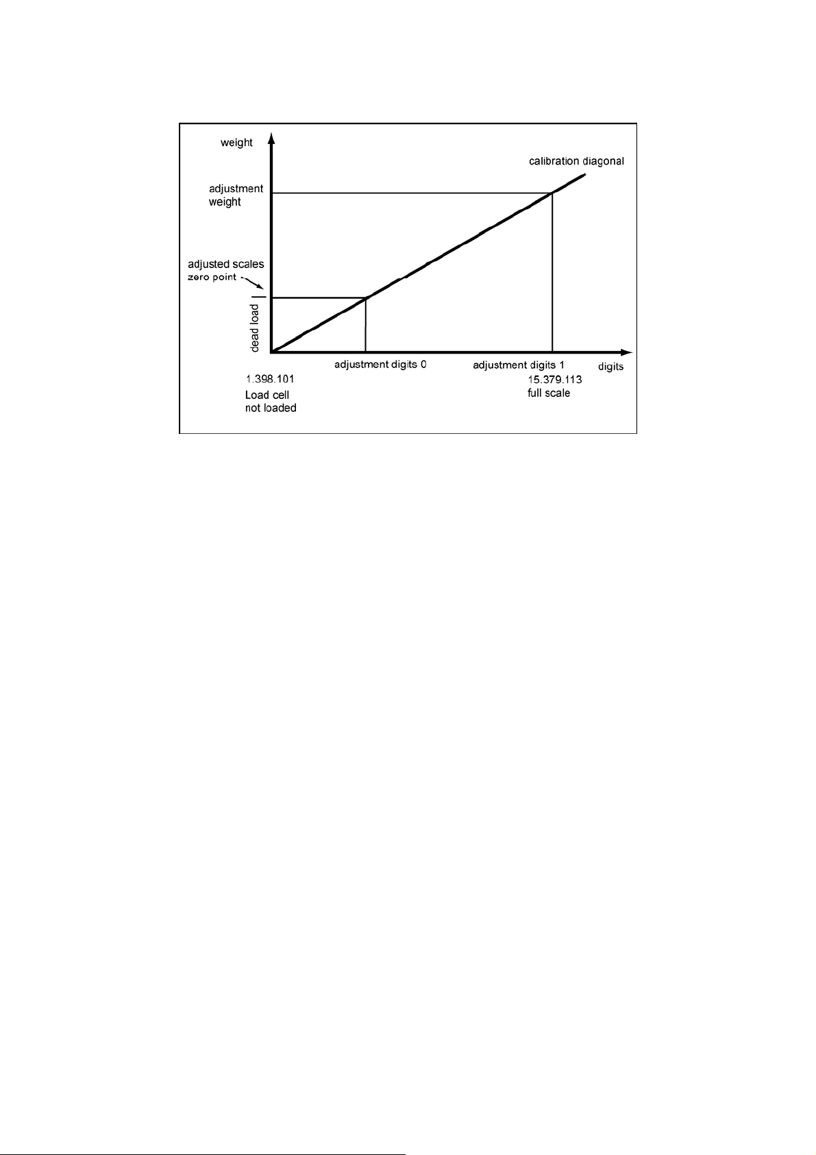
WEIGHING FUNCTIONS AND PARAMETERS
FIGURE 5-1
Adjustment Digits and Weight Value
If the adjustment weights and adjustment digits of a SIWAREX FTC are known then
the adjustment procedure does not need to be performed. They are simply sent to
the SIWAREX FTC in the DR3 data record and the scale is immediately operational
(after official calibration of the scale, it is no longer possible to send DR3).
The SIWATOOL FTC program supports you in quickly performing and adjustment.
Option 1:
After commissioning and after adjustment, all data records for the scale are read
from SIWAREX FTC and are stored as a scale file ScaleX.FTL.
Identical scales can now be put into operation immediately. Connect the PC to the
new scale and activate the "Send all data records" function. This also transfers the
adjustment weights and the adjustment digits - the characteristic curve is defined
immediately. Of course, the same applies for exchanging a SIWAREX FTC.
Option 2:
Use the SIWATOOL FTC „Theoretical adjustment“ function and determine the
characteristic curve of the scale from the technical data of the load cells alone.
The case assumes proper construction of the scale (see
5.3).
SIWAREX FTC
5-37
Page 50
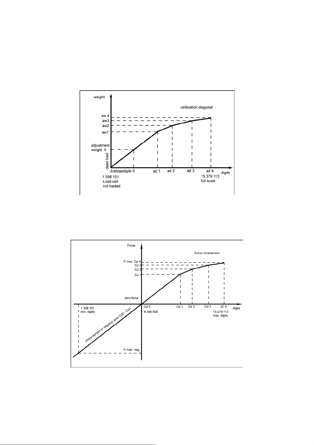
Note
Normally, defining two operating points is sufficient to determine the characteristic
curve for the scale. Other operation points must only be defined on non-linear
systems - New digital values (adjustment digits 2, 3, 4) are assigned with other
calibration weights (e.g. 70%, 80%, 100% of the measurement range).
FIGURE 5-2
Linearization of the scale characteristic curve
The characteristic curve is converted for bi-directional operation in "Force
measurement" operating mode. The following image shows the relationship
between effective force and the adjustment digits.
FIGURE 5-3
5-38 SIWAREX FTC
Adjustment Digits and Force
Page 51
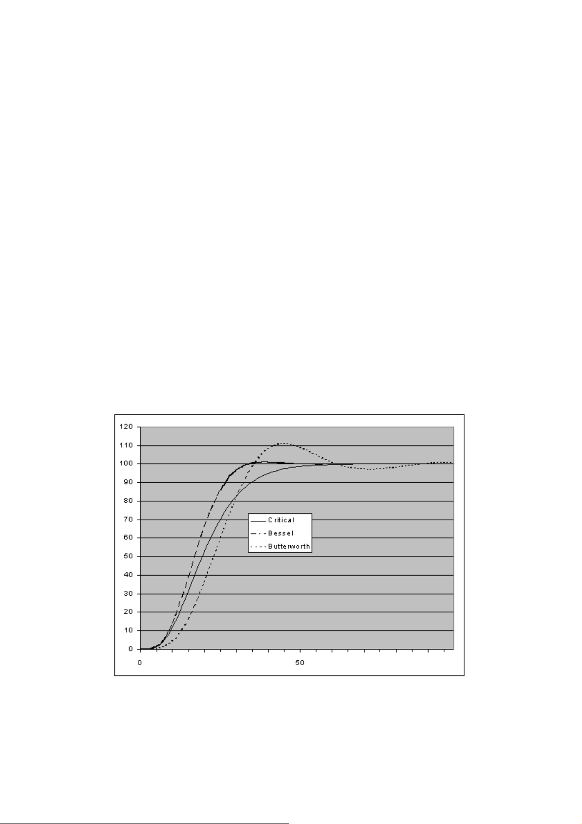
WEIGHING FUNCTIONS AND PARAMETERS
DR3 - Characteristic Value Range
5.2.2
ending on the characteristic value of the connected load cells, the value
Dep
1 mV/V, 2 mV/V or 4 mV/V must be selected. Since the SIWAREX FTC supplies
the load cells with approximately 10 V, the measuring input is redefined according
to the expected measurement voltage (max. 10 mV, max. 20 mV or max. 40 mV).
For example, if the characteristic value of the connected load cells is 2.85 mV/V
then the next higher characteristic value must normally be set, i.e. 4 mV/V.
For bi-directional force measurement, the characteristic value range should be
defined as +/-.
5.2.3 DR3 – Filter Sequence for the Signal Filter
nging the filter sequence can be an advantage in some cases. Normally,
Cha
the signal is first filtered by the average value filter.
5.2.4 DR3 - Type of Low-Pass Filters
For the supp
been prepared for selection (critically damped, Bessel filter, Butterworth filter).
The selection is performed empirically. The following images show the step
response of the three filters (fg = 2 Hz).
For the suppression of the interferences in average values, separate filters are
ctivated in the parameters for the respective operating mode. a
ression of interference to the weight display, 3 types of filters have
FIGURE 5-4 Step responses of the digital low-pass filter
SIWAREX FTC
5-39
Page 52

5.2.5 DR3 - Limit Frequency
Defining the limit frequency is critically important for suppressing interference.
The "speed" of the scale's reaction to the change in the measured value is
determined by specifying the limit frequency.
A value of e.g. 2 Hz leads to a relatively quick scale reaction to a weight change,
a value of e.g. 0.5 Hz makes the scale "sluggish".
5.2.6 DR3 - Depth of Average Value Filters
The average
The weight value is based on the average of the n weight values that the
SIWAREX FTC calculates every 10 msec, e.g. if n=10, 10 values are used for
calculating the average value. Every 10 ms, the oldest value drops out of the
calculation and the newest is considered in the calculation.
5.2.7 DR3 - Scale Name
The nam
Note
The scale name can no longer be changed after official calibration.
5.2.8 DR3 - Number of Weight Ranges
SIWAREX FTC ca
measurement ranges. Depending on the construction type certification, the
numeral step can be defined separately for every range. Normally, only one
measuring range is used in the force measurement and continuous weighing (belt
scale, bulk flow measurement device) operating modes.
5.2.9 DR3 - Scale Type
If the number of range
multi-range scale or a multi-resolution scale.
value filter is used to settle the weight value against interference.
e consists of a maximum of 10 characters and can be freely selected.
n be defined as a scale with one, two or three different
s is greater than one then the scale type can be defined as a
Information on the function of a multi-range- or multi-resolution-scale can be found
in EN 45 501.
Note
If only one range is defined then this entry is meaningless.
5.2.10 DR3 - Activate Zero Setting upon Switching On
The scale
On verifiable scales, a weight value of +/- 10% of the max. measurement range
can be set to zero on start-up.
can be set to zero automatically by switching the supply voltage on.
5-40 SIWAREX FTC
Page 53

WEIGHING FUNCTIONS AND PARAMETERS
!
Attention
In non-verifiable operation (no OIML restrictions), a full scale can also be set to
zero after activating this function. Limiting the effectiveness is possible by entering
the max. and min. weight however. See Max. Min. weight for zero setting upon
switch-on. In operating modes "Belt scale" and "Loss-in-weight scale", this function
cannot be activated.
5.2.11 DR3 - Activated Zero Setting upon Switch On, If Scale Tared
The scale
If the function above is activated, there is still the question of whether zero setting
at start-up should be run if the tare weight is unequal to zero.
If yes, the tare weight is also deleted with the zero setting and if no, no zero setting
is performed on the scale.
5.2.12 DR3 - Automatic Zero Adjustment
Zero
required. The automatic zero adjustment sets the scale to zero without an
instruction if it slowly drifts away from the zero point. Slow drifting is presumed if
the conditions of standard EN45501 have been met. This function is executed as a
dynamic zero setting function in the "Belt scale" operating mode.
can be set to zero automatically by switching the supply voltage on.
setting the scale can be performed with the "Zero setting" instruction if
This function has no effect in the "Loss-in-weight scale" operating mode.
!
Attention
In non-verifiable operation (no OIML restrictions), after activating this function,
the scale can indicate zero after a slow drift over time if it is full. When using this
function, overloading the scale must be prevented with suitable measures.
5.2.13 DR3 - Minimum Weight for Weighing Range 1
The cu
step for measurement range 1) only above the minimum weight. The minimum
weight is defined by an adjustment or a calibration. The minimum weight depends
on the number and type of load cells used.
The value can be set to 0 on non-calibrating scales.
5.2.14 DR3 - Maximum Weight for Weighing Range 1
The cu
measurement range 1) only under the maximum weight. The maximum weight is
defined during adjustment. The maximum weight depends on the number and type
of load cells used and the required weight range.
rrent weight value can be used for verifiable recording (with the numeral
rrent weight can be used for calibrating purposes (with the numeral step for
SIWAREX FTC
5-41
Page 54

5.2.15 DR3 - Minimum Weight for Weighing Range 1
The numeral step for weighing range 1 can be defined corresponding with standard
EN 45501 (0.0001 to 50).
5.2.16 DR 3 - Minimum Weight for Weighing Range 2
The cu
step for measurement range 2) only above the minimum weight. The minimum
weight is defined by an adjustment or a calibration. The minimum weight depends
on the number and type of load cells used. The value can be set to 0 on noncalibrating scales.
Note
If only one weighing range is defined (such as e.g. for the belt scale or loss-inweight scale), then this definition is meaningless.
5.2.17 DR 3 - Maximum Weight for Weighing Range 2
The cu
measurement range 2) only under the maximum weight. The maximum weight is
defined during adjustment.
The maximum weight depends on the number and type of load cells used.
Note
If only one weighing range is defined then this entry is meaningless.
5.2.18 DR 3 - Minimum Weight for Weighing Range 2
The num
EN 45501 (0.0001 to 50).
rrent weight value can be used for verifiable recording (with the numeral
rrent weight can be used for calibrating purposes (with the numeral step for
eral step for weighing range 2 can be defined corresponding with standard
If only one weighing range is defined then this entry is meaningless.
5.2.19 DR 3 - Minimum Weight for Weighing Range 3
The cu
step for measurement range 3) only above the minimum weight. The minimum
weight is defined by an adjustment or a calibration. The minimum weight depends
on the number and type of load cells used.
The value can be set to 0 on non-calibrating scales.
Note
If only one or two weighing ranges are defined then this entry is meaningless.
5.2.20 DR 3 - Maximum Weight for Weighing Range 3
The cu
measurement range 3) only under the maximum weight. The maximum weight is
defined during adjustment.
The maximum weight depends on the number and type of load cells used.
Note
If only one or two weighing ranges are defined then this entry is meaningless.
rrent weight value can be used for verifiable recording (with the numeral
rrent weight can be used for calibrating purposes (with the numeral step for
5-42 SIWAREX FTC
Page 55
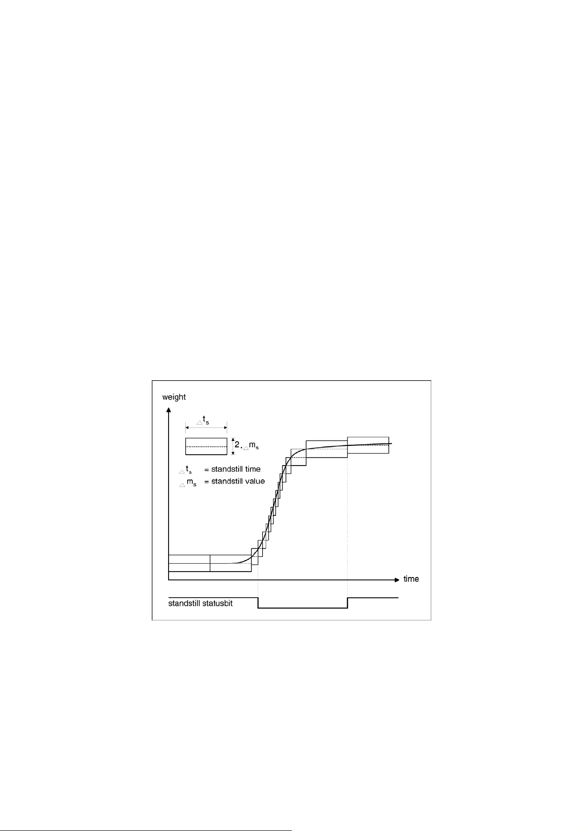
WEIGHING FUNCTIONS AND PARAMETERS
5.2.21
DR 3 - Numeral Step for Weighing Range 3
The num
EN 45501 (0.0001 to 50).
Note
If only one or two weighing ranges are defined then this entry is meaningless.
5.2.22 DR 3 - Standstill Time
Standstill mo
Scale standstill is determined if the weight value changes by less than a defined
deviation range (standstill value) within a defined time (standstill time). Standstill is
used in static operation of the scale (Command: Zero setting, Taring, Output log).
5.2.23 DR 3 - Standstill Range
Standstill mo
Scale standstill is determined if the weight value changes by less than a defined
deviation range (standstill value) within a defined time (standstill time). Standstill is
used in static operation of the scale (Command: Zero setting, Taring, Output log).
T he figure below illustrates the functioning of the standstill monitoring feature.
eral step for weighing range 1 can be defined corresponding with standard
nitoring is used to identify when the scale is at a stable equilibrium.
nitoring is used to identify when the scale is at a stable equilibrium.
FIGURE 5-5
5.2.24 DR 3 - Waiting Time for Standstill
SIWAREX FTC
Standstill Monitoring
To preve
setting in static operation) immediately when the stable weight of the scale is not
defined, the waiting time is given as standstill. If the scale instruction tare, output
nt having to cancel a weighing instruction (only taring, printing and zero
5-43
Page 56

log or zero setting was not possible after this time has elapsed then the
corresponding technology message generated.
5.2.25 DR 3 - Maximum Negative Weight for Zero Setting upon Switch On
setting means that an automatic zero setting is performed for the scale when
Zero
the supply voltage is switched on.
If zero setting upon switching on the supply voltage has been activated, then the
definition will limit the affect of the function. The reference point for the
effectiveness of the limitation is not the current weight, it is the weight that was
displayed by the scale without a previous zero setting. In operating modes "Belt
scale" and "Loss-in-weight scale", this function is not effective.
5.2.26 DR 3 - Maximum Positive Weight for Zero Setting upon Switch On
setting means that an automatic zero setting is performed for the scale when
Zero
the supply voltage is switched on.
If zero setting upon switching on the supply voltage has been activated, then the
definition will limit the affect of the function. The reference point for the
effectiveness of the limitation is not the current weight, it is the weight that was
displayed by the scale without a previous zero setting. In operating modes "Belt
scale" and "Loss-in-weight scale", this function is not effective.
5.2.27 DR 3 - Maximum Negative Weight for Zero Setting
The cu
For zero setting, the specification can be used to limit the effect of the function.
The reference point for the affect of the limitation is not the current gross weight.
It is the weight that the scale would show without a previous zero setting.
For scales in calibrating operation, the limit between the negative and positive
weight for zero setting is 4% of the maximum weighing range.
5.2.28 DR 3 - Maximum Positive Weight for Zero Setting
For zero setti
The reference point for the effectiveness of the limitation is not the current weight,
it is the weight that was displayed by the scale without a previous zero setting.
For scales in calibrating operation, the limit between the negative and positive
weight for zero setting is 4% of the maximum weighing range.
5.2.29 DR 3 - Tare max. Weight T-
SIWAREX FTC acce
maximum weighing range with multi-range scales or weighing range 1 with a multiresolution scale.
On scales in verifiable application, the value is limited to 100% of the maximum
weighing range.
rrent gross weight of the scale is defined as zero for zero setting.
ng, the specification can be used to limit the effect of the function.
pts every weight value which is less than %-record of the
5.2.30 DR 3 – Operating Mode
This pa
weighing operating modes applies depending on the task description.
5-44 SIWAREX FTC
rameter can be used to select the suitable weighing program. One of these
Page 57

WEIGHING FUNCTIONS AND PARAMETERS
Defining
the operating mode is done during the initial commissioning of the
module by sending the adjustment data record DR 3 with the newly defined
operating mode.
Data records or individual parameters, which have no effect in a certain operating
mode, are also taken and stored in the SIWAREX FTC module.
The following operating modes can be defined:
- 0 - non-automatic weighing instrument (OIML R 76) for fill scales
- 0 - non-automatic weighing instrument (OIML R 76) for emptying scales
- 2 - Force measurement (bi-directional)
- 3 – Belt scale (Default value, Description in separate manual)
- 4 - Loss-in-weight scale
- 5 - Bulk flow measurement device
5.2.31 DR 3 - Weighing Operating Mode: NAWI Filling Procedure
Non
-automatic weighing instrument (NAWI) - according to OIML R-76 - only
accepts the service and adjustment instructions and weighing instructions "zero
setting" and "taring". The net weight increases with increasing load on the scale.
5.2.32 DR 3 - Operating Mode: NAWI Emptying Procedure
-automatic weighing instrument (NAWI) - according to OIML R-76 - only
Non
accepts the service and adjustment instructions and weighing instructions "zero
setting" and "taring". The net weight increases with decreasing load on the scale.
5.2.33 DR 3 - Operating Mode: Force Measurement
This op
erating mode is not legal-for-trade. The scope of functionality is similar,
but with operating mode "non-automatic weighing instrument filling procedure".
The difference is in the ability to use the measuring range in the positive and
negative direction.
5.2.34 DR 3 - Operating Mode: Belt Scale
In operatin
g mode Belt scale, the parameters from the DR 5 are also evaluated.
The scope of functionality is designed for operation with a belt scale. The belt scale
is described in a separate manual.
5.2.35 DR 3 - Operating Mode: Loss-in-weight Scale
In operatin
g mode Loss-in-weight scale, the adjustment parameters from data
records DR 6, DR 10, DR 11, DR 12 and DR 13 are also evaluated. The scope of
functionality is designed for operation with a loss-in-weight scale.
5.2.36 DR 3 - Operating Mode: Bulk Flow Measurement Device
In operatin
the DR 55 are also evaluated. The scope of functionality is designed for operation
with a bulk flow measurement device.
SIWAREX FTC
g mode Bulk flow measurement device, the adjustment parameters from
5-45
Page 58

5.2.37 DR 3 - Load cell type
Analog load cells (strain gauge full bridge sensor) as well as sensorsfrom
the Mettler Toledo type WM or WMH can be connected to the SIWAREX
FTC. This information defines which interface that the signal comes from:
- via the connection with strain gauge analog load cells
- via RS 485 with sensors type WM or WMH
After selecting the sensors METTLER TOLEDO Type WM or WMH,
settings must be made in data record DR 7 for the RS485 interface (see
4.4.10 )
In data record 3, the adjustment digits and adjustment weight must be
defined:
o Adjustment digits for zero point = 8388608
o Adjustment digits 1 = 13388608
o Adjustment digits 2, 3, 4 = 0
o Adjustment weight 1 = 5000000/ digital value per weight unit e.g. if
10000d/kg was sent from the sensor 5000000/10000=500
o Adjustment digits 2, 3, 4 = 0
The application-dependent sensor parameters are set using the tools for
defining parameters for the WM or WMH sensors.
The following settings (with instructions) must be made for communication
with SIWAREX FTC:
- RS422 interface settings:
o PROT_2 (Basic protocol)
o COM_1_8_0_0 (Interface RS422, 38400 baud, 7 Bits, even
parity, 1 stop bit)
- Setting the digital inputs:
o DIN1_SIR_0_1 (Input 1 for the SIR instruction, positive edge,
output via RS422)
o DIN1_SI_0_1 (Input 1 for the SIR instruction, positive edge,
output via RS422)
5.2.38 DR 3 – Monitoring time for the digital load cells
The receipt of the cyclic weight telegrams from the load cell type types WM,
WMH is monitored. If no telegram is received for the defined time period (in
ms), SIWAREX FTC indicates an operational fault No. 24 – Digital load cell
not ready. A status bit also provides (Status NAWI, Bit 29) the information
on whether the digital load cell is ready. If the status bit is not set, the
5-46 SIWAREX FTC
Page 59

WEIGHING FUNCTIONS AND PARAMETERS
weight values are not evaluated because no plausible weight values have
been received.
5.2.39 DR 3 - Regulations
Scales in calibrating operation are subject to certain restrictions. The "OIML" entry
activates these restrictions. To deactivate them, it is necessary to enter "----".
The entry „OIML“ only makes sense if the scale is to be verifiable as a nonautomatic weighing instrument.
5.2.40 DR 3 - Weight Unit
sition character sequence can be defined as the unit of measurement,
A 4-po
e.g.: g, kg, lbs
5.2.41 DR 3 – Large Weight Unit
A 4 characte
The relationship between the mass unit of measurement and the measured unit of
measurement is determined with a factor e.g. 1,000. The large weight unit is
advantageous when defining quantities that refer to a longer period of time,
e.g. belt quantities per hour.
5.2.42 DR 3 - Length Unit (belt scale only)
The length u
to this definition.
The parameter only has an effect in the operating mode "Belt scale".
5.2.43 DR 3 - Conversion Factor
The co
large weight unit. The factor can be defined as required.
Example:
Weight unit: kg
Large weight unit: t
Conversion factor 1000,0
5.2.44 DR 3 – Determination Time (belt scale only)
r string can be defined as the unit of measurement e.g.: t.
nit is used for defining the belt length. Calculating the belt load refers
nversion factor indicates the relationship between the weight unit and the
With a static
immediately after activating the instruction during the adjustment. Zero setting is
also executed immediately when defining a stable weight.
A determination time can also be defined for this instruction for the belt scale. The
scale runs the determination of the operation point during the defined
determination time as an average value of all measurements and the average
value is output after the determination time has elapsed.
The determination time applies for the following instructions: zero point valid,
adjustment weight 1...4 valid, zero setting, taring.
Example:
SIWAREX FTC
scale (determination time = 0), the operation points are determined
5-47
Page 60

If the determination time is set to 10 000 ms, a new weight is determined e.g. every
10 ms with the "Zero setting"instruction. After 10 seconds have elapsed,
the average value of all measurements will be defined as a new adjustment point.
5.3 Theoretical Adjustment – Adjustment Without Adjustment Weights
If performing the adjustment is not possible using adjustment weights, the scale
can also be put back into operation without adjustment weights, if the mechanical
structure of the scale is correct and the measuring logs are available for the
individual load cells. Execution is handled with the help of SIWATOOL FTC_B
(not in operating mode "Force measurement") during the processing of the
adjustment parameters. We call the procedure "theoretical adjustment".
First, the characteristic value range (1mV/V, 2mV/V or 4mV/V)must be defined in
the "Adjustment" tab of the data record for the adjustment data. Then, switch to the
"Theoretical adjustment" tab.
To execute the theoretical adjustment, the rated load for all load cells is defined
first, e.g. 3 load cells with 1,000 kg each result in a rated load of 3,000 kg.
The adjustment zero offset (unit μV), and the characteristic value (unit mV/V) is
then entered for each individual load cell. These values are taken from the
respective load cell measurement log. The characteristic value is normally entered
with up to 5 decimal places, e.g. 2.01201.
After entering the data for each load cell, the adjustment digits are calculated and
the result is displayed by actuating the button "Calculate adjustment digits". Then,
the calculated adjustment digits can be integrated into the data record with
adjustment data (DR 3) by actuating button "Accept calculation". The data record is
then sent to the weigh module with the new adjustment data.
Depending on the mechanics of the device, a completely empty scale may indicate
a value that deviates from the adjustment zero slightly. In this case, the instruction
"Characteristic curve shift" can be executed.
5.4 DR 4 Basis Parameter
The basis parameters define other features of a scale, which are responsible for
the basic behavior. The parameters must be checked and sometimes have to be
changed. DR 4 is not subject to write protection in calibrating operation.
Procedures:
o Check all parameters and change if necessary
o Send the DR 4 to the scale
Name Type Address Default Range of Values / Meaning Reference
Reserve_4_0 BYTE DBB000 0 Reserved
Reserve_4_1 BYTE DBB001 0 Reserved
Reserve_4_2 WORD DBW002 0 Reserved
Monitoring time for
recording
Device for log output BYTE DBB008 1 Bit 0 :
TIME DBD004 2000 Time within which, a recording task must be
ended (msec)
0 = Log output to RS232 interface
1 = Log output to MMC
5.4.1
5.4.2
5-48 SIWAREX FTC
Page 61

WEIGHING FUNCTIONS AND PARAMETERS
Name Type Address Default Range of Values / Meaning Reference
Reserve_4_9 BYTE DBB009 0 Reserved
Basis weight for limit
value 1
Basis weight for limit
value 2
Basis weight for the
empty range
Reserve_4_11 BYTE DBB011 0 Reserved
Empty range
Switch-on weight
Limit value 1
Cut-off weight
Limit value 1
Switch-on weight
Limit value 2
Cut-off weight
Limit value 2
Switch-on weight
Limit value 3
Cut-off weight
Limit value 3
40
BYTE DBB010 0
0
REAL DBD012 1
REAL DBD016 1
REAL DBD020 1,1
REAL DBD024 50
REAL DBD028 49
REAL DBD032 99
REAL DBD036 98
Bits 1 to 7 not used
Bit 0 :
0 = Basis for limit value 1 is the gross weight
1 = Basis for limit value 1 is the net weight
Bit1 :
0 = Basis for limit value 2 is the gross weight
1 = Basis for limit value 2 is the net weight
Bit 3 :
0 = Basis for the empty range is the gross
weight
1 = Basis for the empty range is the net
weight
Bits 4 to 7 not used
For filling procedures, this depends on
parameters, for emptying procedures relative
to gross. With the loss-in-weight scale: Limit
value for ending the emptying run.
Switch-on weight
Limit value 1
Cut-off weight
Limit value 1
Switch-on weight
Limit value 2
Cut-off weight
Limit value 2
Limit value 3 corresponds with overfill limit
Cut-off weight limit value 3
5.4.3
5.4.4
5.4.5
5.4.6
5.4.7
5.4.8
5.4.9
5.4.10
5.4.11
5.4.12
Table 5-3 Allocation of DR 4
5.4.1 DR 4 - Monitoring Time for Logging
If logging of the wei
ghing results is generated by an instruction or automatically,
SIWAREX FTC monitors whether the procedure has been completed within the
predefined time. If not, an error is generated.
5.4.2 DR 4 - Device for the Log Output
s can be output to a connected printer or to the Micro Memory Card (MMC).
Log
The contents of the log are defined in data records DR 40 to DR 43.
5.4.3 DR 4 - Basis Weight for Limit Value 1
The limit values can be d
efined in relation to the gross weight or the net weight of
the scale.
5.4.4 DR 4 - Basis Weight for Limit Value 2
The limit values can be d
efined in relation to the gross weight or the net weight of
the scale.
SIWAREX FTC
5-49
Page 62
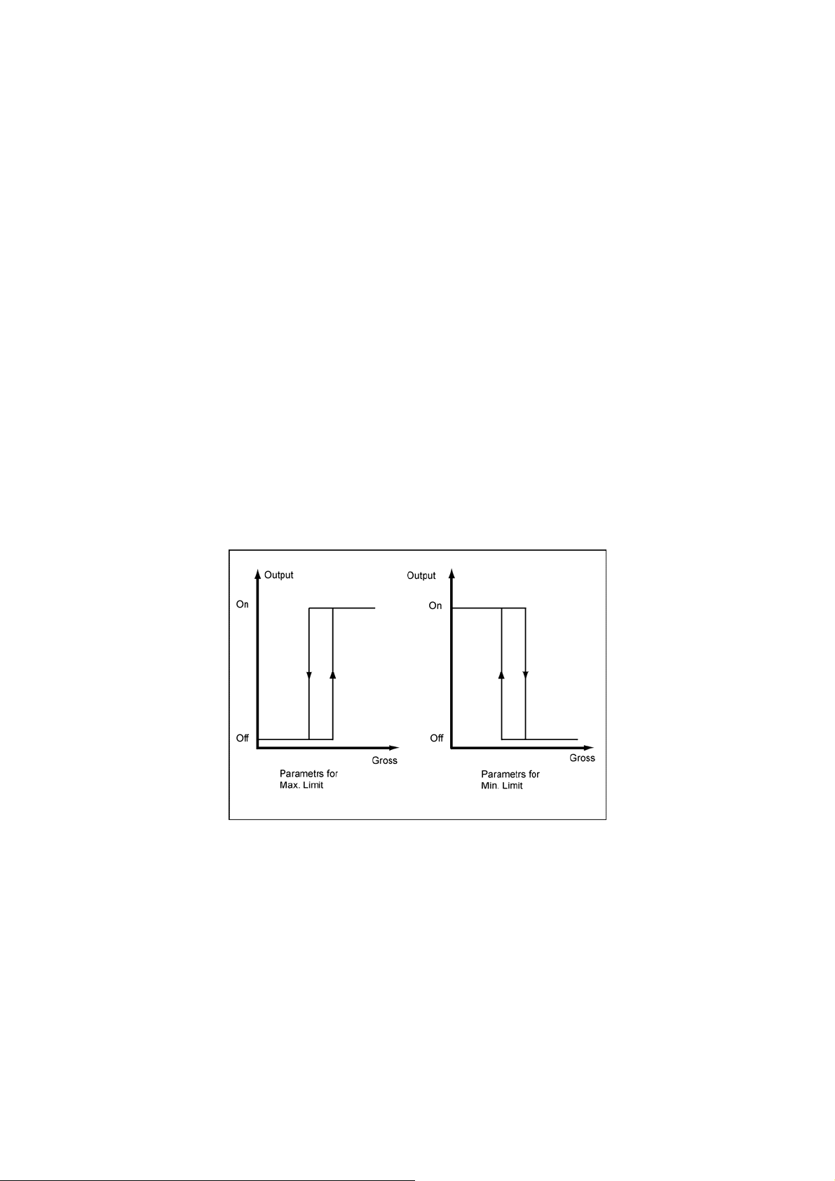
5.4.5 DR 4 - Basis Weight for Monitoring the Empty Range
The limit value for the monitoring of the empty range can be defined in relation to
the gross weight or the net weight of the scale.
5.4.6 DR 4 - Empty Range
The value for
"empty" status to the SIWAREX FTC which gives this out as status information.
In operating mode Loss-in-weight scale, emptying in automatic mode is ended if
the value drops below the limit value.
5.4.7 DR 4 - Switch-on Weight Limit Value 1
-on and shut-off weights can be defined separately for a limit value. In this
Switch
way, a minimum value monitor and a maximum value monitor can be realized by
hysteresis. A maximum value monitor is realized with the following specification:
Switch on value > Switch off value
A minimum value monitor is realized with the following specification:
Switch on value < Switch off value
The following image shows the functionality of limit values 1, 2, 3
the empty range is a limit value, that when exceeded indicates the
FIGURE 5-6
5.4.8 DR 4 - Cut-off Weight Limit Value 1
5.4.9 DR 4 - Switch-on Weight Limit Value 2
5-50 SIWAREX FTC
Defining limit value parameter
See: Switch
See: Switch
On Weight, Limit Value 1
On Weight, Limit Value 1
Page 63

WEIGHING FUNCTIONS AND PARAMETERS
5.4.10
DR 4 - Cut-off Weight Limit Value 2
See: Switch
On Weight, Limit Value 1
5.4.11 DR 4 - Switch-on Weight Limit Value 3
The switch
-on and cut-off weight can be defined separately for the limit value.
With limit value 3, only the maximum weight monitor can be used. The basis weight
for the limit value 3 is always the gross weight.
5.4.12 DR 4 - Cut-off Weight Limit Value 3
n the limit value is undercut, the status information "limit value 3) is reset.
Whe
5.5 DR 5 Belt Scale Parameter
The basis parameter for belt scale defines other features of a scale which are
responsible for the behavior in the belt scale operating mode. The parameter must
be checked and changed in some cases.
Procedure:
o Check all parameters and change if necessary.
o Send the DR 5 to the scale
Name Type Address Default Range of Values / Meaning Reference
Nominal speed
Time basis for belt
speed
Pulse constant
Constant belt speed
Minimum belt speed INT DBW016 800 Limit value for minimum belt speed in % of
Maximum belt speed INT DBW018 1020 Limit value for maximum belt speed in % of
Reaction time for belt
monitor
At start
Reaction time for belt
monitor
During operation
Reserve_5_28 REAL DBD028 Reserved
Nominal flow-rate
Effective belt length
Correction factor for
flow-rate
Minimum flow-rate INT DBD044 Limit value for minimum flow-rate in % of the
Maximum flow-rate INT DBD046 Limit value for maximum flow-rate in % of the
REAL DBD000 0
TIME DBD004 0 Time basis for measuring the belt speed by
REAL DBD008 0 Pulse constant of the speed sensor
REAL DBD012 2000 Constant speed if no speed sensor is
TIME DBD020 Reaction time for belt monitoring and belt
TIME DBD024 Reaction time for belt monitoring and belt
REAL DBB032 Nominal flow-rate in weight units / s
REAL DBB036 Effective belt length in length units LU
REAL DBB040 Correction factor for the flow rate
Nominal speed of the belt in LU/s (Length
units per second)
impulse counter input (msec)
connected.
0 – for connecting the speed sensor.
the nominal speed.
800 corresponds with 80.0 %
the nominal speed.
1020 corresponds with 102.0 %
cycle error message at belt start
cycle error message during belt operation
nominal flow-rate
nominal flow-rate
5.5.1
5.5.2
5.5.3
5.5.4
5.5.5
5.5.6
5.5.7
5.5.8
5.5.9
5.5.10
5.5.11
5.5.12
5.5.13
SIWAREX FTC
5-51
Page 64

Name Type Address Default Range of Values / Meaning Reference
Minimum belt loading INT DBB048 Limit value for minimum belt loading in % of
Maximum belt loading INT DBB050 Limit value for maximum belt loading in % of
Dyn. zero setting range INT DBB052 Maximum belt loading with zero setting.
Minimum belt loading
for totalizing
Delay time for
monitoring the belt
loading / flow-rate at
start
Delay time for
monitoring the belt
loading / flow-rate in
operation
Totalizing value in WU
Totalizing value in LWU REAL DBD068 0.1 Numeral step (‚Totalizing value’) f. the
Quantity per pulse 1
Pulse duration 1 f.
Digital output
Minimum pause
duration 1 for digital
output
Quantity per pulse 2
Pulse duration 2 f.
Digital output
Minimum pause
duration 2 for digital
output
Overload-UndercutInhibition time
Reserved
102
INT DBW054 Limit value for minimum belt loading in % of
TIME DBD056 Delay time after switching on the belt until
TIME DBB060 Delay time in continuous operation of the belt
REAL
REAL DBD072 0 Indicates, after which quantity increase for
TIME DBD076 0
TIME DBD080 0
REAL DBD084 0 Indicates, after which quantity increase that a
TIME DBD088 0
TIME DBD092 0
TIME DBD096 0 Time delay for the error messages which are
REAL DBW100 0 Reserved
DBD064 0.1 Numeral step (‚Totalizing value’) f. the
the nominal belt loading
the nominal belt loading
the nominal belt loading for totalizing
monitoring the belt loading or flow-rate.
until monitoring of the belt loading or flowrate.
totalizing memory (Group 1) 1...4 in weight
unit WU
totalizing memory (Group 2) 5...8 in large
weight unit LWU
group 1 that a pulse should be output (when
an external totalizing counter is connected))
Pulse duration 1 for outputting the required
quantity to a digital output (when an external
totalizing counter is connected 1)
(50 ....1000ms)
Minimum pause duration 1 for output of the
required quantity to digital output (when an
external totalizing counter is connected ) 50
....1000ms
pulse should be output. (when an external
totalizing counter is connected 2)
Pulse duration group 2 for the output of the
required quantities to a digital output (when a
totalizing counter is connected)
50 ....1000ms
Minimum pause duration group 2 for output of
the required quantity to a digital output (when
a totalizing counter is connected)
50 ....1000ms
caused by overloading or undercutting the
measuring range
5.5.14
5.5.15
5.5.16
5.5.17
5.5.18
5.5.19
5.5.20
5.5.21
5.5.22
5.5.23
5.5.24
5.5.25
5.5.26
5.5.27
5.5.28
FIGURE 5-7 Defining belt scale parameter parameter
5.5.1 DR 5 – Nominal speed
The nominal speed of the belt corresponds with the speed at nominal
conditions, i.e. at nominal load on the belt. This is output in LU (length
units) per second e.g. 1.7 m/sec.
5.5.2 DR 5 – Time basis for the belt speed
The belt speed is output in LU (length units) per second. The measuring
time of the pulse input can be set to another time e.g. 2 seconds. That
5-52 SIWAREX FTC
Page 65

WEIGHING FUNCTIONS AND PARAMETERS
means that the speed value output is updated every 2 seconds, the value
will still be defined in LU per second however.
5.5.3 DR 5 – Pulse constant
The pulse constant of the speed sensor indicates the number of pulses per
LU (length unit) of the belt. SIWAREX FTC calculates the current belt
speed on this basis.
5.5.4 DR 5 – Constant belt speed
Constant speed must be defined if no speed sensor is connected. The
calculation of the flow-rate is then performed using this value.
When a speed sensor is connected, the value must be set to 0.
5.5.5 DR 5 – Minimum belt speed
Minimum belt speed is a limit value for minimum belt speed in % of the
nominal speed. The entry of the number e.g. 800 corresponds with 80.0 %.
After this value has been undercut, SIWAREX FTC sets a status bit (see
scale status...).
5.5.6 DR 5 – Maximum belt speed
Maximum belt speed is a limit value for maximum belt speed in % of the
nominal speed. The entry of the number e.g. 1020 corresponds with 102.0
%. After this value has been exceeded, SIWAREX FTC sets a status bit
(see scale status...).
5.5.7 DR 5 – Reaction time for belt monitoring at start
Monitoring the belt speed is only activated after this delay time when the
belt is started.
5.5.8 DR 5 – Reaction time for belt monitoring in operation
When the minimum belt speed is undercut, the message or status bit is
only activated after this delay time has elapsed.
5.5.9 DR 5 – Nominal flow-rate
Nominal flow-rate in WU (weight units) / sec is defined by the user.
It corresponds with the flow-rate that the belt is equipped for.
5.5.10 DR 5 – Effective belt length
Effective belt length in length units LU. The effective belt length
corresponds with half of the distance between the belt rollers which are
found before and after the roller with the belt scale.
5.5.11 DR 5 – Correction factor for belt loading
A material test can be performed to compare the actual required material
quantity with the total calculated by SIWAREX FTC. A correction factor can
be defined for the calculation of the flow-rate quantity for small deviations.
SIWAREX FTC
5-53
Page 66

5.5.12 DR 5 – Minimum flow-rate
Minimum flow-rate is a limit value for minimum flow-rates in % of the
nominal flow-rate. The entry of the number e.g. 800 corresponds with 80.0
%. After this value has been undercut, SIWAREX FTC sets a status bit.
5.5.13 DR 5 – Maximum flow-rate
Maximum flow-rate is a limit value for maximum flow-rates in % of the
nominal flow-rate. The entry of the number e.g. 1020 corresponds with
102.0 %. After this value has been exceeded, SIWAREX FTC sets a status
bit.
5.5.14 DR 5 – Minimum belt loading
Minimum belt loading is a limit value for minimum belt loading in % of the
nominal belt loading. The entry of the number e.g. 800 corresponds with
80.0 %. After this value has been undercut, SIWAREX FTC sets a status
bit. In batch mode the totalizing will be completed after the dosing signal is
switched off and the belt loadin is less than this limit value.
5.5.15 DR 5 – Maximum belt loading
Maximum belt loading is a limit value for maximum belt loading in % of the
nominal belt loading. The entry of the number e.g. 1020 corresponds with
102.0 %. After this value has been exceeded, SIWAREX FTC sets a status
bit.
5.5.16 DR 5 – Maximum belt loading for zero setting
Maximum belt loading for zero setting is a limit value for maximum belt
loading in % of the nominal belt loading. Entering the number e.g. 20
corresponds with 2.0 %. After this value has been exceeded, SIWAREX
FTC will not execute the zero setting instruction.
5.5.17 DR 5 - Minimum belt loading for totalizing
Minimum belt loading for totalizing is a limit value for minimum belt loading
in % of the nominal belt loading. Entering the number e.g. 20 corresponds
with 2.0 %. After the actual value is less than the limit, SIWAREX FTC will
not execute the totalizing function.
5.5.18 DR 5 – Delay time for the monitoring of the belt loading after the start
After the belt is switched on, undercutting the minimum belt loading or the
minimum flow-rate is only indicated after this time has elapsed.
5.5.19 DR 5 – Delay time for monitoring the belt loading in continuous operation
After the minimum belt load has been undercut or the minimum flow-rate is
undercut, the respective message or status bit is output only after this time
has elapsed.
5-54 SIWAREX FTC
Page 67

WEIGHING FUNCTIONS AND PARAMETERS
5.5.20
DR 5 – Numeral step for totals 1...4
The totalizing memory 1...4 is run with the weight unit indicated in data
record 3. The user can define the smallest step for creating a total with the
numeral step.
E.g. weight unit 1 kg, numeral step for creating the total can be 5 kg.
5.5.21 DR 5 – Numeral step for the totals 4...5
Totalizing memory 4...8 is run with large weight unit indicated in data record
3. The user can define the smallest step for creating a total with the
numeral step.
E.g. Weight unit 1 kg, numeral step for totalizing can be 1 t.
5.5.22 DR 5 – Material quantity per pulse 1
The material quantity per pulse 1 indicates, after which quantity increase of
totalizing memory 1.....4 should output a pulse through the defined digital
output.
5.5.23 DR 5 – Pulse duration 1 for the digital output
For the external quantity counter, the pulse duration can be defined so that
the device can recognize the pulse for sure. The pulse duration is not
permitted to be selected so long that stopping the minimum pause duration
will make the next pulse late.
5.5.24 DR 5 – Minimum pause duration 1 for the digital output
For the external quantity counter, the pulse duration can be defined so that
the device can recognize the pulse for sure. The pulse duration is not
permitted to be selected so long that stopping the minimum pause duration
will make the next pulse late.
5.5.25 DR 5 – Material quantity per pulse 2
The material quantity per pulse 2 indicates, after which quantity increase of
totalizing memory 1.....4 1 should output a pulse through the defined digital
output.
5.5.26 DR 5 – Pulse duration 2 for the digital output
For the external quantity counter, the pulse duration can be defined so that
the device can recognize the pulse for sure. The pulse duration is not
permitted to be selected so long that stopping the minimum pause duration
will make the next pulse late.
5.5.27 DR 5 – Minimum pause duration 2 for the digital output
For the external quantity counter, the pulse duration can be defined so that
the device can recognize the pulse for sure. The pulse duration is not
permitted to be selected so long that stopping the minimum pause duration
will make the next pulse late.
SIWAREX FTC
5-55
Page 68

5.5.28 DR 5 – Over and under-load inhibition time
When undercutting or exceeding the measurement range, a fault is
indicated. For the defined inhibition time, the fault message is suppressed.
If the status remains for a longer period of time, the fault message is output.
5.6 DR 7 Interfaces
The parameters that define the behavior of the SIWAREX FTC on the interfaces
are defined in DR 7. If an interface is not used the default values can be left alone.
o Change parameter if required.
o Send the DR 7 to the scale
Name Type Address Default Range of Values / Meaning Reference
S7-Interface 0
Reserved BYTE DBB000 0
Source for the weight
simulation
Decade used for
rounding the decimal
places of the process
values
(REAL-weight values)
Reserved
Force service operation BYTE DBB004 0 Bit 0 :
Process value 1 for fast
output to the SIMATIC
CPU
Process value 2 for fast
output to the SIMATIC
CPU
Reserve 2
S7-Alarm
Definition of the process
alarm 0
BYTE DBB001 0 0: Weight simulation inactive
1: Weight simulation value from SIMATIC
2: Weight simulation value from RS232
Other definitions not permitted.
BYTE DBB002 3 0: rounding to 0 decimal places
1: rounding to 1 decimal place
2: rounding to 2 decimal places
3: rounding to 3 decimal places
4: rounding to 4 decimal places
5: rounding to 5 decimal places
6: rounding to 6 decimal places
BYTE DBB003 0 Reserved
0: Outputs in service operation Forced control
impossible
1: Outputs in service operation Forced control is
possible
Bit 1 - 7 not used
BYTE DBB005 2 Various process values are available for selection
after listing.
BYTE DBB006 30 Various process values are available for selection
after listing.
BYTE DBB007 0 Reserve 2
WORD DBW008 0 Value 0 - No process alarm generation
Value range 1 – 0FFh
Number of the technical error
Value range 100h – 13Fh
100h+ 0...1Fh Bit-No. NAWI-status bit - coming
100h+ 20h...3Fh Bit-No. Conti status flag-coming
Value range 200h – 23Fh
200h+ 0...1Fh Bit-No. NAWI status bit - going
200h+ 20h...3Fh Bit-Nr. Conti status bit-going
5.6.1
5.6.2
5.6.3
5.6.4
5.6.5
5.6.6
5-56 SIWAREX FTC
Page 69

WEIGHING FUNCTIONS AND PARAMETERS
Name Type Address Default Range of Values / Meaning Reference
Definition of the process
alarm 1
Definition of the process
alarm 2
Definition of the process
alarm 3
Definition of the process
alarm 4
Definition of the process
alarm 5
WORD DBW010 0 Value 0 - No process alarm generation
Value range 1 – 0FFh
Number of the technical error
Value range 100h – 13Fh
100h+ 0...1Fh Bit-No. NAWI-status bit - coming
100h+ 20h...3Fh Bit-No. Conti status bit-coming
Value range 200h – 23Fh
200h+ 0...1Fh Bit-No. NAWI status bit - going
200h+ 20h...3Fh Bit-Nr. Conti status bit-going
WORD DBW012 0 Value 0 - No process alarm generation
Value range 1 – 0FFh
Number of the technical error
Value range 100h – 13Fh
100h+ 0...1Fh Bit-No. NAWI-status bit - coming
100h+ 20h...3Fh Bit-No. Conti status bit-coming
Value range 200h – 23Fh
200h+ 0...1Fh Bit-No. NAWI status bit - going
200h+ 20h...3Fh Bit-Nr. Conti status bit-going
WORD DBW014 0 Value 0 - No process alarm generation
Value range 1 – 0FFh
Number of the technical error
Value range 100h – 13Fh
100h+ 0...1Fh Bit-No. NAWI-status bit - coming
100h+ 20h...3Fh Bit-No. Conti status bit-coming
Value range 200h – 23Fh
200h+ 0...1Fh Bit-No. NAWI status bit - going
200h+ 20h...3Fh Bit-Nr. Conti status bit-going
WORD DBW016 0 Value 0 - No process alarm generation
Value range 1 – 0FFh
Number of the technical error
Value range 100h – 13Fh
100h+ 0...1Fh Bit-No. NAWI-status bit - coming
100h+ 20h...3Fh Bit-No. Conti status bit-coming
Value range 200h – 23Fh
200h+ 0...1Fh Bit-No. NAWI status bit - going
200h+ 20h...3Fh Bit-Nr. Conti status bit-going
WORD DBW018 0 Value 0 - No process alarm generation
Value range 1 – 0FFh
Number of the technical error
Value range 100h – 13Fh
100h+ 0...1Fh Bit-No. NAWI-status bit - coming
100h+ 20h...3Fh Bit-No. Conti status bit-coming
Value range 200h – 23Fh
200h+ 0...1Fh Bit-No. NAWI status bit - going
200h+ 20h...3Fh Bit-Nr. Conti status bit-going
5.6.6
5.6.6
5.6.6
5.6.6
5.6.6
SIWAREX FTC
5-57
Page 70

Name Type Address Default Range of Values / Meaning Reference
Definition of the process
alarm 6
Definition of the process
alarm 7
S7 - FB Life bit
monitoring time
Analog output 0
Weight for zero point
(0 or 4 mA)
Reference for end value
(20 mA)
Replacement value for
the analogue output at
OD
Source for the analog
output
Current range for the
analogue output
RS232 0
RS232-printer baud rate
WORD DBW020 0 Value 0 - No process alarm generation
Value range 1 – 0FFh
Number of the technical error
Value range 100h – 13Fh
100h+ 0...1Fh Bit-No. NAWI-status bit - coming
100h+ 20h...3Fh Bit-No. Conti status bit-coming
Value range 200h – 23Fh
200h+ 0...1Fh Bit-No. NAWI status bit - going
200h+ 20h...3Fh Bit-Nr. Conti status bit-going
WORD DBW022 0 Value 0 - No process alarm generation
Value range 1 – 0FFh
Number of the technical error
Value range 100h – 13Fh
100h+ 0...1Fh Bit-No. NAWI-status bit - coming
100h+ 20h...3Fh Bit-No. Conti status bit-coming
Value range 200h – 23Fh
200h+ 0...1Fh Bit-No. NAWI status bit - going
200h+ 20h...3Fh Bit-Nr. Conti status bit-going
TIME DBD024 0 0 = S7- Life bit monitor switched off
1 to n = Monitoring time [msec]
REAL DBD028 0 Value output with the 0 or 4 mA
REAL DBD032 0 Value output with the 20 mA.
REAL DBD036 0 Replacement value which is output with an active
OD signal if the parameters are defined
respectively
BYTE DBB040 0 0 = Control signals-SIMATIC
1 = ext. default value through DR 17
2 = Gross
3 = Net
4 = Belt speed
5 = Flow rate 1
6 = Belt load Other definitions not allowed
7 = Actuation signal PID controller
BYTE DBB041 0 Bit 0:
0: 0 .. 20mA
1: 4 .. 20mA
Bit 1 – 7 unused
BYTE DBB042 3 0 = 1200 Bit/sec.
1 = 2400 Bit/sec.
2 = 4800 Bit/s
3 = 9600 Bit/s
Other definitions not permitted.
5.6.6
5.6.6
5.6.7
5.6.8
5.6.9
5.6.10
5.6.11
5.6.12
5.6.13
5-58 SIWAREX FTC
Page 71

WEIGHING FUNCTIONS AND PARAMETERS
Name Type Address Default Range of Values / Meaning Reference
RS232- XON/XOFF for
printer
RS232- RTS/CTS for
printer
RS485 0
Log selection
Decimal place for the
remote display
RS485-Baudrate
RS485-character parity
RS485- Data bits
RS485-Stop-Bits
Digital outputs 0
Definition of digital output
1
Definition of the digital
output 2
Definition of the digital
output 3
Definition of the digital
output 4
BYTE DBB043 1
0
0
BYTE DBB044 0 0: no protocol
BYTE DBB045 0 0 to 4
BYTE DBB046 3 0 = 1200 Bit/sec.
BYTE DBB047 0
1
0
BYTE DBB048 0FFh Value range 00h – 3Fh
BYTE DBB049 0FFh Value range 00h – 3Fh
BYTE DBB050 0FFh Value range 00h – 3Fh
BYTE DBB051 0FFh Value range 00h – 3Fh
Bit 0:
0: XON/XOFF transmission control OFF
1: XON/XOFF transmission control ON
Bit 1:
0: CTS/RTS transmission control OFF
1: CTS/RTS transmission control ON
Bit 2: reserved, must always be 0
Bit 3 – 7 unused
1: SIEBERT- Protocol S11
2: ASCII protocol
3: SIEBERT- Protocol S102 (6-position)
Other definitions not permitted.
1 = 2400 Bit/sec.
2 = 4800 Bit/s
3 = 9600 Bit/s
4 = 19200 Bit/s
Other definitions not permitted.
Bit 0:
0: even
1: odd
Bit 1:
0: 7 data bits
1: 8 data bits
Bit 2:
0: 1 stop bit
1: 2 stop bit
Bit 3 – 7 not used
0...1Fh Bit-No. NAWI status flag
20h...3Fh Bit-No. Conti status flag
41h....Pulse output Integration Distribution mem.1
42h... Pulse output Integration Distribution mem.5
FFh output always inactive
0...1Fh Bit-No. NAWI status flag
20h...3Fh Bit-No. Conti status flag
FFh output always inactive
0...1Fh Bit-No. NAWI status flag
20h...3Fh Bit-No. Conti status flag
FFh output always inactive
0...1Fh Bit-No. NAWI status flag
20h...3Fh Bit-No. Conti status flag
FFh output always inactive
5.6.14
5.6.15
5.6.16
5.6.17
5.6.18
5.6.19
5.6.19
5.6.19
5.6.19
SIWAREX FTC
5-59
Page 72

Name Type Address Default Range of Values / Meaning Reference
Definition of the digital
output 5
Definition of the digital
output 6
Definition of the digital
output 7
Definition of the digital
output 8
Level definition for digital
outputs 1....8
Replacement values for
digital outputs 1 .... 8
upon fault or OD signal
Activate - Digital output
replacement values for
operational faults
Reserve 3
Digital inputs 0
Definition of digital input 1 BYTE DBB060 0 0 = No command
Definition of the digital
input 2
Definition of the digital
input 3
Definition of the digital
input 4
Definition of the digital
input 5
Definition of the digital
input 6
Definition of the digital
input 7
Level definition for digital
inputs 1...7
Reserved
BYTE DBB052 0FFh Value range 00h – 3Fh
0...1Fh Bit-No. NAWI status flag
20h...3Fh Bit-No. Conti status flag
FFh output always inactive
BYTE DBB053 0FFh Value range 00h – 3Fh
0...1Fh Bit-No. NAWI status flag
20h...3Fh Bit-No. Conti status flag
FFh output always inactive
BYTE DBB054 0FFh Value range 00h – 3Fh
0...1Fh Bit-No. NAWI status flag
20h...3Fh Bit-No. Conti status flag
FFh output always inactive
BYTE DBB055 0FFh Value range 00h – 3Fh
0...1Fh Bit-No. NAWI status flag
20h...3Fh Bit-No. Conti status flag
FFh output always inactive
BYTE DBB056 0 Bit 0: DO1 -> 0 = high active: 1 = low active
....
Bit 7: DO8 -> 0 = high active: 1 = low active
BYTE DBB057 0 Bit 0: Replacement value digital output 1
....
Bit 7: Replacement value digital output 8
BYTE DBB058 0 Bit 0:
0: Replacement value output for operating error
deactivated
1: Replacement value for operating error
activated
Bit 1 - 7 not used
BYTE DBB059 0 Reserve 3
1- 254 = Command code
BYTE DBB061 0 0 = No command
1- 254 = Command code
BYTE DBB062 0 0 = No command
1- 254 = Command code
BYTE DBB063 0 0 = No command
1- 254 = Command code
BYTE DBB064 0 0 = No command
1- 254 = Command code
BYTE DBB065 0 0 = No command
1- 254 = Command code
BYTE DBB066 0 0 = No command
1- 254 = Command code
BYTE DBB067 0 Bit 0: Digital input 1 -> 0 = high active: 1 = low
active
....
Bit 6: Digital input 7 -> 0 = high active: 1 = low
active
Bit 7: Not used
TIME DBD068 0 Reserved
5.6.19
5.6.19
5.6.19
5.6.19
5.6.20
5.6.21
5.6.22
5.6.23
5.6.23
5.6.23
5.6.23
5.6.23
5.6.23
5.6.23
5.6.24
5-60 SIWAREX FTC
Page 73

WEIGHING FUNCTIONS AND PARAMETERS
Name Type Address Default Range of Values / Meaning Reference
Reserve 4
MMC Parameter 0
Log overflow
Trace overflow
Memory for trace
Memory segment for
trace function
Memory segment for logs
Trace function Recording
cycle
80
DWORD DBB072 0 Reserve 4
BYTE DBB076 1
1
0
BYTE DBB077 50 Up to 100% but the total for trace function and log
BYTE DBB078 50 Up to 100% but the total for trace function and log
BYTE DBB079 1 1...n x 10 msec
Bit 0:
0: with full memory, the logging procedure is
stopped
1: with full memory, the oldest
entries are overwritten
Bit 1:
0: No overwriting of trace data is possible
1: the oldest trace data is overwritten with full
card
Bit 2:
0: Trace data is stored in RAM
1: Trace data is stored in the MMC
Bit 3 – 7 not used
may not exceed 100%
may not exceed 100%
5.6.25
5.6.26
5.6.27
5.6.28
Table 5-4 Allocation of DR 7
5.6.1 DR 7 - Source for the Weight Simulation
Instead of the
actual weight determination, a weight simulation can be activated for
test purposes. The simulated weight value can be defined through the SIMATIC
interface or through the RS232 interface (SIWATOOL FTC). The weight simulation
makes commissioning the scale much easier in certain situations.
5.6.2 DR 7 - Decade for Rounding the Decimal Places for the Process Values
This pa
rameter can be used to define to how many decimal places that the
(weight) process values should be rounded. This entry decouples the display of
weight values which trigger the restrictions of the calibration requirements from the
values that are used in the control software.
5.6.3 DR 7 - Force in Service Operation
After activating this functio
n, the digital outputs can be forced independent of their
parameter definitions. Force control is only possible in service operation and only
with the SIMATIC interface.
SIWAREX FTC
5-61
Page 74

!
Warning notice
Before using this function, you must ensure that the system will not reach any
hazardous status caused by the forced control of the digital outputs of the
SIWAREX FTC.
5.6.4 DR 7 - Process Value 1 for Fast Output to the SIMATIC CPU
The cu
SIMATIC CPU using function block FB43. Transferring a large data record can last
for several CPU cycles and puts a load on system performance.
If a process value should be transferred very quickly to the SIMATIC CPU
immediately after its origination in the SIWAREX FTC, the peripheral interface of
the SIWAREX FTC exists. The data is read by the FB43 cyclically and provided for
the user as an output variable. In the belt scale operating mode, normally the
current belt load (selection code 45) is of some importance. Selection is from the
list See:
5.6.5 DR 7 - Process Value 2 for Fast Output to the SIMATIC CPU
Process valu
Normally the current Conti status (selection code 30) is of interest in the loss-inweight scale operating mode.
rrent process values can be read as data packages (data records) in the
Table 5-21 Process values for allocating log fields.
e 2 can be defined just the same as process value 1 (see above).
5.6.6 DR 7 - Definition of the Process Alarms 0, 1, 2, 3, 4, 5, 6, 7
The process
generate process alarms in the SIMATIC CPU. The control program can react
immediately to an event this way. Defining a process alarm is explained with the
example of process alarm 0. The explanation also applies to process alarms 1 to 7.
If parameter value 0 is defined for process alarm 0 then no process alarms are
generated.
By entering a value unequal to zero, a process alarm is allocated according to the
following procedures:
Value range 1 to 255
Number of the technology message. If the defined technology error occurs then
process alarm 0 is generated.
Value range 256 to 319
Number of the bit from the NAWI- or Conti status (see DR 30). If the defined status
occurs then process alarm 0 is generated.
256+ 0... 31 Bit-No. NAWI status bit coming
288+ 0... 31 Bit-No. Conti status bit coming
Value range 512 to 575
Number of the bit from the NAWI- or Conti status (see DR 30). If the defined status
goes then process alarm 0 is generated.
512+ 0... 31 Bit-No. NAWI status bit going
544+ 0... 31 Bit-No. Conti status bit going
alarms can be defined with this parameter. The module group can
5-62 SIWAREX FTC
Page 75

WEIGHING FUNCTIONS AND PARAMETERS
5.6.7
DR 7 - S7-FB-Life Bit Monitoring Time
The SIWARE
X FTC can determine whether the FB is maintaining the
communication with the SIMATIC CPU by monitoring the life bit. If the FB does not
respond, an operating error is output after the defined time has elapsed. Monitoring
is active in RUN status of the SIMATIC_CPU.
5.6.8 DR 7 – Input Value for the Adjustment Zero (0 or 4 mA)
A weight for the ran
ge start can be defined when defining the range parameters for
the analogue output.
5.6.9 DR 7 - Input Value for the End Value (20 mA)
n defining the parameters for the range for the analog output, a weight can be
Whe
defined for the range end.
5.6.10 DR 7 - Replacement Value for the Analog Output with OD
A weight ca
n be defined for the analogue output, for which a corresponding signal
is output if the OD signal (Output Disable) exists.
Normally this corresponds with the SIMATIC CPU status - STOP.
5.6.11 DR 7 - Source for the Analog Output
The so
urce for the analogue output can be defined with this parameter. The weight
values from the defined source are output as current signals corresponding with
the parameter definitions for start and end ranges.
The following sources are available:
0 - Control value form the SIMATIC (FB)
1 - Default value from the DR 17
2 - Gross weight
3 - Net weight
4 - Belt speed
5 - Flow rate 1
6 - Belt load
7 - Actuation signal from PID controller
5.6.12 DR 7 - Current Range for the Analog Output
The anal
og output can be operated with a current range 0... 20 mA or 4... 20 mA.
SIWAREX FTC
5-63
Page 76

5.6.13 DR 7 - RS232 Printer Baudrate
If a printer is connected to the RS232 interface, the following baud rates can be
defined.
1200 Bit/sec
2400 Bit/sec
4800 Bit/sec
9600 bps
5.6.14 DR 7 - RS232 Transmission Control for Printer
The tran
follows:
XON/XOFF (for printer protocol only)
RTS/CTS (for printer protocol only)
5.6.15 DR 7 – Protocol Selection for RS 485
The followi
- 0: No protocol
5.6.16 DR 7 - Decimal Place for the Remote Display
sfer control parameters for the RS232 interfaces can be defined as
0: XON/XOFF transmission control OFF
1: XON/XOFF transmission control ON
0: CTS/RTS transmission control OFF
1: CTS/RTS transmission control ON
ng protocols can be set for the RS485 interface
1: SIEBERT- Protocol S11
2: ASCII protocol
3: SIEBERT- Protocol S102 (6-position)
If a display from the Siebe
the decimal place for the display of non-verifiable process values can be defined.
5.6.17 DR 7 – RS 485 Baudrate
The followi
0 = 1200 Bit/sec.
1 = 2400 Bit/sec.
2 = 4800 Bit/s
3 = 9600 Bit/s
4 = 19200 Bit/s
5-64 SIWAREX FTC
ng protocols can be set for the RS485 interface:
rt company is connected to the RS 485 interface,
Page 77

WEIGHING FUNCTIONS AND PARAMETERS
5.6.18
DR 7 - RS485 Character Frame
Parity:
0: even
1: odd
Numb
er of data bits
0: 7 data bits
1: 8 data bits
Number of stop bits:
0: 1 Stop bit
1: 2 Stop bits
5.6.19 DR 7 - Definition of the Digital Outputs 1, 2, 3, 4, 5, 6, 7, 8
The definition
of the digital outputs can be defined with this parameter. Assigning a
bit from the pool of status bits for the scale causes the output to be active (active
can be signal level 0 or 1 - see below) if the bit is set.
When assigning a number between 0 and 63, the digital output is assigned to a
status bit of the scale and when assigning a number > 63, the output remains
inactive.
0... 31 Bit-No. NAWI status flag
31 + 0... 31 Bit-No. Conti status flag
253 Start MW transmission digital LC
254 Stop MW transmission digital LC
255 Output always inactive
Other values not allowed
5.6.20 DR 7 - Level Definition for Digital Outputs 1 to 8
After assi
gning the definitions for digital outputs to a status bit, the signal that the
output should have when it is active can be determined.
E.g. Digital output 1 (DO1) is determined with bit 0:
If bit 0 is 0 then DO1 is high active and if bit 0 is 1 then DO1 is low active,
If bit 1 is 0 then DO2 is high active and if bit 1 is 1 then DO2 is low active,
etc.
SIWAREX FTC
5-65
Page 78

5.6.21 DR 7 - Replacement Values for DO 1 to 8 with Fault or Output Disable
Normally, the outputs are reset with a SIMATIC CPU STOP. This behavior
corresponds with the default setting.
If it makes sense to set an output with a SIMATIC CPU STOP, you can define it
with this parameter.
E.g. Digital output 1 (DO1) is determined with bit 0:
If bit 0 is 0 then DO1 is also 0 with OD signal.
If bit 0 is 1 then DO1 is 1 with OD signal.
The digital output 1 (DO2) is determined with bit 1:
If bit 1 is 0 then DO2 is also 0 with OD signal.
If bit 1 is 1 then DO2 is 1 with OD signal.
etc.
!
Warning notice
If an output is to be set with the SIMATIC CPU STOP then you must ensure that it
does not lead to a hazardous situation.
5.6.22 DR 7 - Replacement Values for Digital Outputs with Operating Error
Normally, the outputs a
error). This behavior corresponds with the default setting.
If it makes sense to set an output with a fault, you can define it with this parameter.
E.g. Digital output 1 (DO1) is determined with bit 0:
If bit 0 is 0 then DO1 is also 0 with fault.
If bit 0 is 1 then DO1 is 1 with fault.
The digital output 1 (DO2) is determined with bit 1:
If bit 1 is 0 then DO2 is also 0 with fault.
If bit 1 is 1 then DO2 is 1 with fault.
etc.
re reset when there is a module group fault (operating
Warning
If an output is to be set with the fault (operating error) then you must ensure that it
does not lead to a hazardous situation.
5-66 SIWAREX FTC
Page 79

WEIGHING FUNCTIONS AND PARAMETERS
DR 7 - Definition of Digital Inputs 0, 1, 2, 3, 4, 5, 6, 7
5.6.23
The definition
happen by allocating an instruction.
Commands:
If the signal 1 appears at the defined input then the assigned command is
executed. To allocate and instruction to an input, its instruction number (1 to 255)
must be entered (see Command List). By entering 0, the input is assigned as
sed.
unu
5.6.24 DR 7 - Level Definition for Digital Inputs 1 to 7
After assi
you can define which signal that the should be interpreted as active on the input.
E.g. Digital input 1 (DI1) is determined with bit 0:
If bit 0 is 0 then DI1 is high active and if bit 0 is 1 then DI1 is low active,
If bit 1 is 0 then DI2 is high active and if bit 1 is 1 then DI2 is low active,
etc.
5.6.25 DR 7 - MMC Log Overflow, MMC Trace Overflow, Target Memory for Trace Function
Bit 0 is used f
MMC memory when the memory is full.
of the digital inputs can be defined with this parameter. This can
gning the definition for digital inputs to a command or a step-on condition,
or defining how the logging should be performed in the verifiable
0: with full memory, the logging procedure is stopped
1: with full memory, the oldest entries are overwritten
Bit 1 is used for defining how the logging of trace data should continue if memory is
full.
0: No overwriting of trace data is possible with full MMC memory
1: The oldest trace data is overwritten with full MMC memory
The trace function is described in
Bit 2 defines which memory is used for recording the trace data.
0: Trace data is stored in RAM
1: Trace data is stored in the MMC
The trace function is described in
5.6.28
5.6.28
SIWAREX FTC
5-67
Page 80

5.6.26 DR 7 - Memory Segment for Trace Function
The MMC memory can be used for recording the trace data and for recording the
verifiable scale logs.
The percentage of MMC memory that is available for the trace function is defined
with this parameter.
Up to 100% is permitted in this definition but the total for trace function and
verifiable log may not exceed 100%
The trace function is described in
5.6.27 DR 7 - Memory Segment for Log
The MM
verifiable scale logs.
The percentage of MMC memory that is available for the verifiable logs is defined
with this parameter.
Up to 100% is permitted in this definition but the total for trace function and
verifiable log may not exceed 100%
The trace function is described in
5.6.28 DR 7 - Trace Function Recording Cycle
Every n-th measure
is possible and when recording to MMC, n 5 is possible.
The recording can be started with the "Start Recording" 70 command and stopped
with "End recording" 71 command.
A recording element has a length of 64 bytes and contains several measurement
values and status bits (
The values that are recorded can be read with the SIWATOOL FTC and can then
be exported into MS EXCEL.
C memory can be used for recording the trace data and for recording the
ment (n x 10 msec) is recorded. When recording to RAM, n 1
see Table 5-26 Combination of recording elements).
5.6.28
5.6.28
If the trace function is defined as recording into cyclic memory then it can be used
to construct a status recorder. The command for starting the recording can come
from the SIMATIC control program and the command for stopping can also come
from the control program, e.g. if you want to record and save the progress of a
procedure.
5.7 DR 8 Date / Time
SIWAREX FTC has its own hardware clock. The actual date and time can be read
through DR 8. The date and time can be set on the module group using this data
record if required.
Procedures:
o Setting the date and time.
o Send the DR 8 to the scale
5-68 SIWAREX FTC
Page 81

WEIGHING FUNCTIONS AND PARAMETERS
Name Type Address Default Range of Values / Meaning Reference
Date / Time
Date / Time
4
DATE_AN
D_TIME,
DT
DBD000 01.01.01
00:00:00
000 Mo
Date&Time in SIMATIC-Format
Table 5-5 Allocation of DR 8
5.8 DR 9 Info on Module
No entries can be made in DR 9. The data record uses the information on the inner
life of the module.
Name Type Address Default Range of Values / Meaning Reference
Info on module
CRC Checksum
Length of firmware in
bytes
Product Info
Module name
Application
File name
Version recognition
Function status
Data structure version
Correction status
Creation date
Creation time
DWORD DBW000 0 -
DWORD DBW004 0 -
STRING
[26]
STRING
[10]
STRING
[4][8]
STRING
[20]
BYTE
[4]
STRING
[10]
STRING
[8]
DBB008 0 Siemens AG Serial number of the module
DBB036 SIWAREX
DBB048
DBB082 0
DBB104 0 Byte 0 (ASCII)
DBB108 0
DBB120 0
XX
„CONT“
„NAWI“
„xxxx“
„xxxx“
„xxxx“
„xxxx“
„xxxx“
xxx“
„x
Application identification
Before delivery approval
B = Laboratory status
P = Pilot
R = Release
S = Special status
After delivery approval
V = Version
K = Correction status
Byte 1 function status xx (important function
changes or technical changes for the calibration
0 ... 99)
Byte 2 Version DR structure yy (indicates
changes in the data record structure) 0 ... 99
Byte 3 correction status zz (small changes or
error clean-up) 0 ... 99
SIWAREX FTC
5-69
Page 82

Name Type Address Default Range of Values / Meaning Reference
Boot loader version
Scale type
Reserved WORD DBW138 0 Reserved
140
Table 5-6 Allocation of DR 9
5.8.1 DR 9 - Info on Module
WORD DBW130 0
STRING
[4]
DBB132 „CONT„
or
„NAWI“
The inform
ation on the SIWAREX FTC module is for the purpose of identifying the
module in the manufacturer's plant (e.g. for repairs). This information has no
influence on user operation.
5.9 DR 14 Tilt angle
DR 14 is used for an external definition of the tilt angle for the belt scale.
Procedure:
o Enter tilt angle
o Send DR 14 to the scale
Name Type Address Default Range of Values / Meaning Reference
Tare entry
Tilt angle entry
2
Table 5-7 Allocation of DR 14
5.9.1 DR 14 – Tilt angle definition for the belt
DR 14 is used for an external definition of the belt tilt angle. If the belt is
mounted horizontally, the definition is 0. The belt can be tilted to a
maximum of 60°.
INT DBB000 0 Definition for the belt tilt 0° to 60° (0...600)
5.9.1
Always ensure that the definition corresponds with the current tilt angle,
otherwise the belt load will be calculated incorrectly.
5.10 DR 15 Tare Entry
DR 15 is used for external specification of the tare weight.
Procedures:
o Enter tare weight
o Send the DR 15 to the scale
o Activate the command "Accept tare entry (24)"
5-70 SIWAREX FTC
Page 83

WEIGHING FUNCTIONS AND PARAMETERS
Name Type Address Default Range of Values / Meaning Reference
Tare entry
Tare entry
4
REAL DBD000 0 External tare entry (Preset Tare).
5.10.1
Table 5-8 Allocation of DR 15
5.10.1 DR 15 - Tare Entry
5 is used for external specification of the tare weight. Once specified with
DR 1
DR 15, the tare value is not yet activated. The transfer to tare memory of the
SIWAREX FTC is then performed with instruction „Accept tare entry“
(see command code
24).
5.11 DR 16 Weight simulation entry
If the DR 16 was defined as the source for the weight simulation (see DR 7 Source
for the weight
the measurement input of the SIWAREX FTC and the defined value is "simulated"
as the weight value.
simulation), defining a weight value through DR 16 will deactivate
Procedures:
o Check in DR 7, whether DR 16 has been defined as the source for the weight
simulation
o Enter a value to be simulated
o Send the DR 16 to the scale
Name Type Address Default Range of Values / Meaning Reference
Simulation
Weight simulation entry REAL DBD000 0 Default value for weight simulation (is used
instead of the gross weight e.g. for test)
4
5.11.1
Table 5-9 Allocation of DR 16
5.11.1 DR 16 - Weight Simulation Definition
If the DR 16 wa
for the weight
s defined as the source for the weight simulation (see DR 7
Source
simulation), defining a weight value through DR 16 will deactivate
the measurement input of the SIWAREX FTC and the defined value is "simulated"
as the weight value. This way, plant components (including filter settings) can be
tested even though the scale is not set up yet.
5.12 DR 17 Analog Output Control
If DR 17 has been defined as the source for the analogue output (see DR 7
Source for the analog output) then sending a weight value will output a
corresponding output stream on the analogue output.
Procedures:
o Check in DR 7, whether DR 17 was defined as the source for the analog output.
o Check the parameter definitions of the analog output (see DR 7
SIWAREX FTC
zero point
5-71
Weight for
and following parameters).
Page 84
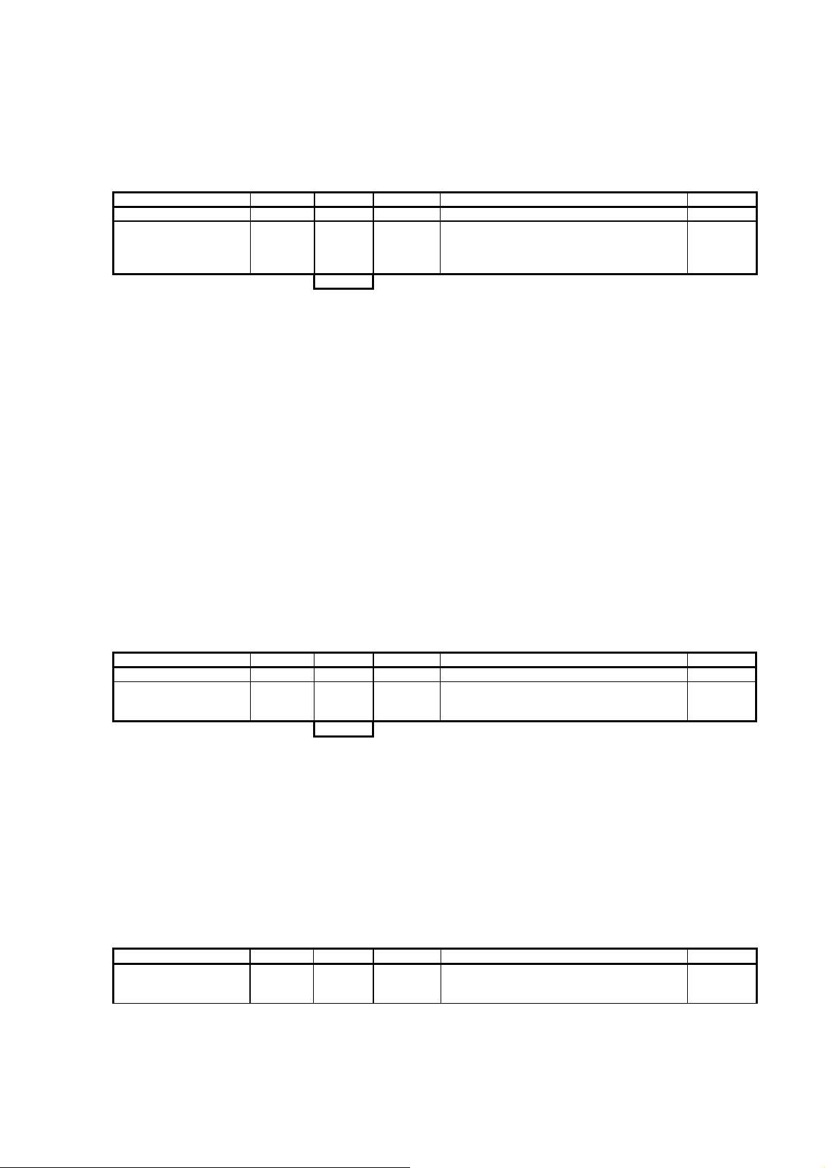
o Enter a value in DR 17
o Send DR 17 to the scale
Name Type Address Default Range of Values / Meaning Reference
Analog output
Ext. definition for analog
output
4
Table 5-10 Allocation of DR 17
5.12.1 DR 17 - Ext. Definition for Analog Output
REAL DBD000 0 Analogue output control with a default value.
5.12.1
If the DR 17 has b
(see DR 7
DR 7 - Source for the ) then the analogue output is controlled with the
een defined as the source for controlling the analogue output
defined value with a definition of a weight value on DR 17. This way, the analogue
output can be set continuously from the SIMATIC control program.
5.13 DR 18 Control Display for Non-automatic Weighing Instrument
A value can be preset using DR 18 and this value can be displayed on the external
display. This way, the external display (Siebert) can be used for displaying any
value that is calculated in SIMATIC. The display can only be used in operating
mode "Non-automatic weighing instrument".
Procedures:
o Enter a value in DR 18
o Send the DR 18 to the scale
Name Type Address Default Range of Values / Meaning Reference
Display
Ext. definition for remote
display
4
Table 5-11 Allocation of DR 18
REAL DBD000 0 Remote display control (Siebert S102) with a
default value
5.14 DR 21 Parameter for batch operation
In batch operation, the entire quantity of the material to be loaded is loaded.
The scale runs the loading according to the predefined total quantity.
Procedures:
o Define set weight
o Send DR 21 to the scale
Name Type Address Default Range of Values / Meaning Reference
Load set value
5-72 SIWAREX FTC
REAL DBD000 0 Quantity to be dosed in batch operation
in reference to WU,
Switch off in reference with totalizing memory 1
5.14.1
Page 85

WEIGHING FUNCTIONS AND PARAMETERS
Name Type Address Default Range of Values / Meaning Reference
Maximum loading time
Trailing weight REAL DBD008 0 Quantity that still must be dosed after reaching
Reserve_21_12
Log selection BYTE DBB016 0 0: No automatic logging
Reserve_21_17
18
TIME DBD004 0 0: deactivated
REAL DBD012 0 Reserved
BYTE DBB017 0 Reserved
If 0, the continuous operation
>100: time f. Monitoring the maximum loading
time.
the set value
performed
1: autom. logging with text 1
2: autom. logging with text 2
3: autom. logging with text 3
4: autom. logging with text 4
5.14.2
5.14.3
5.14.4
Table 5-12 Allocation of DR 21
5.14.1 DR 21 – Loading quantity
The total quantity for loading operation can be set using this parameter.
The belt is stopped when the total quantity is achieved in totalizing memory
1 and the totalizing is ended. For loading the predefined quantity again,
totalizing memory 1 must be deleted.
5.14.2 DR 21 – Maximum loading time
The maximum loading time is started as well when loading is started. If the
total quantity is not achieved before this time has elapsed, SIWAREX FTC
sends out a technology message.
5.14.3 DR 21 – Trailing weight
The trailing weight is the material quantity that must be weighed in addition
after the set value has been reached..
5.14.4 DR 21 – Log Selection
After the total quantity has been reached, a log can be created
automatically. One of four log text messages can be defined with this
parameter.
5.15 DR 30 Process Status 1 (NAWI, Force measurement, Belt scale)
The process values and the expanded process values can be used to monitor the
current states and data in the non-automatic weighing instrument. Observing the
selected data is very helpful in test operation for optimizing parameters. The status
can also be monitored if the SIWAREX FTC is controlled by the SIMATIC CPU.
The NAWI- and Conti-status flags are simultaneously updated in DR 32 as well process status loss-in-weight scale.
Name Type Address Range of Values / Meaning Reference
NAWI status flags DINT DBD000 Status bits (see below)
SIWAREX FTC
5-73
5.15.1
Page 86

Name Type Address Range of Values / Meaning Reference
Conti-Status flags DINT DBD004 Status bits (see below)
Gross process value REAL DBD008 Gross weight
Net process value REAL DBD012 Net weight
Tare process value REAL DBD016 Tare weight
G/N weight
B/N weight_x10
Tare weight
Belt speed REAL DBD032 Current speed [LU/s]
Belt speed in %
Belt load in % INT DBW038 Belt load in relation with the nominal belt load
Nominal belt load
Belt load REAL DBD044 Current belt load [WU/LU]
Flowrate 1 REAL DBD048 Flowrate 1 [WU./s]
Flowrate 2 REAL DBD052 Flowrate 2 [WU/h]
Flowrate 3 REAL DBD056 Flowrate 3 [LWU/h]
Flowrate in % INT DBW060 In reference to the nominal flowrate
Operating hours counter
Pulse counter value DINT DBD064 Pulse counter value in reference to the set
68
REAL DBD020 Verifiable B/N weight value for display and
REAL DBD024 Verifiable B/N weight value with 10 fold
REAL DBD028 Verifiable tare weight value for display and
INT
REAL
INT DBW062 (is not reset, begins after overflow at 0)
DBW036
DBD040
logging purposes (Basis for DR ASCII weight
value)
resolution (Basis for DR ASCII weight value)
logging purposes
Belt speed in % related to the nominal speed
Nominal belt load [WU/LU] calculated from
nominal flowrate and nominal speed
measuring time
5.15.2
5.15.3
5.15.4
5.15.5
5.15.6
5.15.7
5.15.8
5.15.9
5.15.10
5.15.11
5.15.12
5.15.13
5.15.14
5.15.15
5.15.16
5.15.17
5.15.18
5.15.19
Table 5-13 Allocation of DR 30
5.15.1 DR 30 - NAWI Status Bits
Bit No. Name Range of Values / Meaning Reference
0 WR1 Weight within weighing range 1
1 WR2 Weight is in weighing range 2
2 WR3 Weight is in weighing range 3
3 Limit 1 Limit value 1 activated
4 Limit 2 Limit value 2 activated
5 Limit 3 Limit value 3 activated
6 Tared (NET) Set if the scale is tared
7 Preset Tare Set if the scale was tared with tare input
8 Max+9e Set if maximum load is exceeded by 9 e
9 ¼d zero Set if the weight does not exceed ¼ d
10 Waiting for stand-still Set if the scale waits for a stand-still after the weighing
11 Standstill Standstill exists
12 Scale adjusted Set if the scale is adjusted (calibrated)
13 Error on DI
14 Simulation active Set if the weight simulation has been activated
15 Service operation active Set if service operation has been activated
16 Printing log The log is being printed.
17 RS232-Print not possible The log cannot be printed.
18 MMC inserted The MMC is in position
19 MMC ready The MMC is formatted and ready for recording
20 MMC-trace ready The MMC is ready for the trace function
21 MMC-log ready The MMC is ready for logging
22 Trace active The trace function is activated
start.
Set if a command could not be executed on a digital input
5-74 SIWAREX FTC
Page 87

WEIGHING FUNCTIONS AND PARAMETERS
Bit No. Name Range of Values / Meaning Reference
23 Reserved Reserved
24 Reserved Reserved
25 Empty message Scale in empty range
26 Calibration data protection The switch for protecting the calibration data is switched on
27 Reserved Reserved
28 Reserved Reserved
29 Reserved Reserved
30 Standalone operation
activated
31 Operating error At least one operating error (fault) exists
1, if standalone operation has been activated
Table 5-14 DR 30 - NAWI status bits
5.15.2 DR 30 - Conti-Status Flags
Bit No. Name Range of Values / Meaning Reference
0 Belt control status
1 Totalizing status
2 Min. belt loading exceeded Belt loading min has been exceeded (is returned with a
3 Belt loading max. exceeded Belt max has been exceeded (is indicated with a delay in
4 Min. belt speed exceeded Min. belt speed exceeded (returned with a delay in cases)
5 Max. belt speed exceeded Max. belt speed exceeded (is indicated with a delay in
6 Min. pulse undercut
7 Min. belt load exceeded for
totalizing
8 Scale in dynamic zero
setting range
9 Dynamic adjustment or zero
setting procedure is running
10 Dyn. zero setting aborted 1: If dynamic zero setting could not be completed or was
11 Volumetric operation Volumetric operation in automatic mode.
Filling Filling activated.
12
> max. flow rate +/- Change speed of flow rate too great
13
14 > min. flow rate Minimum flow rate achieved
15 > max. flow rate Maximum flow rate exceeded (in relation to the nominal
Pulse 1 external Pulses f. external summator 1
16
Pulse 2 external Pulses f. External summator 2
17
Gravimetric operation Gravimetric mode in automatic operation.
18
Emptying activated The command for emptying was activated. Scale will not
19
Max. control difference Maximum control difference exists.
20
Reserved Reserved
21
22 Max. filling time The maximum filling time has been achieved.
23 Max. time max. control
difference
24 Max. vol. time The volumetric mode is active longer than the defined
25 Reserved Reserved
0: Belt control OFF
1: Belt control ON
1: Recording and totalizing of the dosing quantity is active
0: Dosing quantity will not be recorded
delay in cases)
cases)
cases)
1 = Pulse encoder generates less than 2 pulses / second
0 = Pulse encoder generates a minimum of 2 pulses /
second
1= Min. belt load exceeded for totalizing, the totalizing can
be performed
=1, if the scale is in the dynamic zero setting range
=1, if dynamic adjustment or zero setting procedure is
running
ended early because of leaving the zero setting range
flow rate or setpoint)
refill, the container will empty until the limit value "Empty
range"from DR 4.
The maximum control difference is at the max. defined
monitoring time.
max. monitoring time.
SIWAREX FTC
5-75
Page 88

Bit No. Name Range of Values / Meaning Reference
26 Status change Status change running. The information is set with the
following events:
- Start-up in volumetric operation
- Setpoint change in volumetric operation
- Switch to grav. operation. For the time of the monitoring
delay (DR 12)
- defined switch to volumetr. operation upon flow rate fault
27 Reserved Reserved
28 Dosing active Switch on material discharge organ
29 Loading active Loading (belt scale) is activated.
30 Loading complete Loading (belt scale) is complete.
31 Reserved Reserved
Table 5-15 DR 30 - Conti-Status flags
5.15.3 DR 30 - Gross Process Value
The cu
rrent gross weight value. Dimension: Weight Unit [WU].
5.15.4 DR 30 - Net Process Value
The cu
rrent net weight value. Dimension: Weight Unit [WU].
5.15.5 DR 30 - Tare Process Value
The cu
rrent tare weight value. Dimension: Weight Unit [WU].
5.15.6 DR 30 - G/N Weight
The momentary weight value whi
Weight Unit [WU].
5.15.7 DR 30 - G/N Weight_x10
The momentary weight value in increased resolution whi
main display. Dimension: Weight Unit [WU].
5.15.8 DR 30 - Tare
e current weight value tare (numeral step from DR 3). Dimension: Weight Unit [WU].
Th
5.15.9 DR 30 – Belt Speed
The cu
rrent belt speed defined in length units (e.g. m) per second.
ch will be used for the main display. Dimension:
ch will be used for the
5.15.10 DR 30 – Belt Speed in % of the Nominal Speed
The cu
rrent belt speed in % of the predefined nominal speed.
5.15.11 DR 30 – Belt Loading in % of the Nominal Load
The cu
rrent belt load is output as the relationship of the current belt load to the
nominal belt load.
5-76 SIWAREX FTC
Page 89

WEIGHING FUNCTIONS AND PARAMETERS
5.15.12
DR 30 - Nominal Load
From the n
ominal flowrate (defined in DR 5) and nominal speed (defined in DR 5)
calculated nominal belt load in the dimension weight unit/length unit [WU/LU].
5.15.13 DR 30 - Belt Load
The cu
rrent belt load is output as the relationship of the currently measured weight
to the effective belt length. The dimension is: Weight unit/Length unit [WU/LU].
5.15.14 DR 30 – Flowrate 1
The cu
rrent flowrate 1 is output in the dimension Weight unit / sec [WU/s].
5.15.15 DR 30 – Flowrate 2
The cu
rrent flowrate 2 is output in the dimension Weight unit/h [WU/h].
5.15.16 DR 30 – Flowrate 3
The cu
rrent flowrate 3 is output in the dimension Large Weight Unit / h [LWU/h].
5.15.17 DR 30 – Flowrate in % of the Nominal Flowrate
The cu
rrent flowrate is output in % of the nominal flowrate.
5.15.18 DR 30 – Operating Hours Counter
The ope
rating hours counter records the number of hours that the SIWAREX FTC
is supplied with 24V voltage.
5.15.19 DR 30 – Pulse Counter Value
nt counter value on the pulse input in relation to the defined measurement
Curre
time.
5.16 DR 31 Process Status 2 (all operating modes)
The user or the service technician can retrieve information on the current status of
the scale in the expanded process values.
Name Type Address Range of Values / Meaning Reference
Unfiltered digital value
Filtered digital value
Reserve33_1
Operating error
curr. Date/Time
Current temperature
DINT DBD000 Unfiltered digital value from ADU
DINT DBD004 Filtered digital value from filter level 1 for
DINT DBD008 Reserved
DWORD
DATE_A
ND_TIME
INT DBW024 Current inner-temperature of the module
DBD012
DBD016 curr. Date/Time
NAWI-Fct.
Error word Operating error (for test dept.,
Bit-No. = Error code –1)
[0.1°C]. If no temperature value is available: -
100.0°C.
5.16.1
5.16.2
5.16.3
5.16.4
5.16.5
SIWAREX FTC
5-77
Page 90

Name Type Address Range of Values / Meaning Reference
DE status
Reserve_31_27
Impedance reference
value
Impedance value
32
Table 5-16 Allocation of DR 32
5.16.1 DR 31 – Unfiltered Digital Value
BYTE DBB026
BYTE DBB027
INT
INT
DBW028
DBW030
Current status of the digital inputs (without
pulse input)
Reserve 1
Impedance reference value [0.1]
Impedance actual value [0.1]
5.16.6
5.16.7
5.16.8
The cu
rrent number of digits from the AD converter is output without being filtered.
5.16.2 DR 31 – Unfiltered Digital Value
The cu
rrent number of digits from the AD converter is output after the filtering.
5.16.3 DR 31 – Operating Error
The cu
rrent existing operating errors (fault) are output as double word.
5.16.4 DR 31 – Date Time
The cu
rrent date and time from the internal clock of the SIWAREX FTC.
5.16.5 DR 31 – Max. Temperature
The maximu
m occurring module temperature (slave pointer).
5.16.6 DR 31 – Status of Digital Inputs
The current si
gnal level on the digital inputs 1...6. The status of the input for the
pulse counter is not indicated.
5.16.7 DR 31 - Impedance Reference Value
The total re
sistance of the load cell(s) which is measured upon commissioning.
Measurement is initiated with an instruction.
5.16.8 DR 31 – Impedance Actual Value
nt measures total resistance of the load cell(s). Measurement is initiated with
Curre
an instruction.
5.17 DR 33 Distribution Memory
Totalizing is performed at the same time for every distribution memory location.
The user can delete a certain location at any time which defines the totalizing
period.
Name Type Address Range of Values / Meaning Reference
Distribution memory 1 REAL DBD000 For saving the total quantity related to WU
5-78 SIWAREX FTC
5.17.1
Page 91

WEIGHING FUNCTIONS AND PARAMETERS
Name Type Address Range of Values / Meaning Reference
and rounded to the numeral step
Distribution memory 2
Distribution memory 3
Distribution memory 4
Distribution memory 5
Distribution memory 6
Distribution memory 7
Distribution memory 8
32
REAL DBD004 For saving the total quantity and rounded to
the numeral step WU;
REAL DBD008 For saving the total quantity rounded to the
numeral step WU
REAL DBD012 For saving the total quantity and rounded to
the numeral step WU;
REAL DBD016 For saving the total quantity and rounded to
the numeral step LWU
REAL DBD020 For saving the total quantity and rounded to
the numeral step LWU;
REAL DBD024 For saving the total quantity and rounded to
the numeral step LWU
REAL DBD028 For saving the total quantity and rounded to
the numeral step LWU;
5.17.2
5.17.3
5.17.4
5.17.5
5.17.6
5.17.7
5.16.8
Table 5-17 Allocation of DR 33
5.17.1 DR 33 – Distribution Memory 1
Content of dis
tribution memory. Dimension in weight units [WU]. Can be reset with
instruction „Delete distribution memory 1“ or „Log and delete distribution memory 1“.
5.17.2 DR 33 – Distribution Memory 2
nt of distribution memory. Dimension in weight units [WU]. Can be reset with
Conte
the instruction „Delete distribution memory 2“ or „Log and delete distribution
memory 2“.
5.17.3 DR 33 – Distribution Memory 3
nt of distribution memory. Dimension in weight units [WU]. Can be reset with
Conte
the instruction „Delete distribution memory 3“ or „Log and delete distribution
memory 3“.
5.17.4 DR 33 – Distribution Memory 4
nt of distribution memory. Dimension in weight units [WU]. Can be reset with
Conte
the instruction „Delete distribution memory 4“ or „Log and delete distribution
memory 4“.
5.17.5 DR 33 – Distribution Memory 5
nt of distribution memory. Dimension in Large weight unit [LWU]. Can be
Conte
reset with instruction „Delete distribution memory 5“ or „Log and delete distribution
memory 5“.
5.17.6 DR 33 – Distribution Memory 6
nt of distribution memory. Dimension in Large weight unit [LWU]. Can be
Conte
reset with instruction „Delete distribution memory 6“ or „Log and delete distribution
memory 6“.
SIWAREX FTC
5-79
Page 92

5.17.7 DR 33 – Distribution Memory 7
Content of distribution memory. Dimension in Large weight unit [LWU]. Can be
reset with instruction „Delete distribution memory 7“ or „Log and delete distribution
memory 7“.
5.17.8 DR 33 – Distribution Memory 8
nt of distribution memory. Dimension in Large weight unit [LWU]. Can be
Conte
reset with instruction „Delete distribution memory 8“ or „Log and delete distribution
memory 8“.
5.18 DR 34 ASCII Display Value
The ASCII weight value corresponds with the value on the main display of the
scale.
The data record is displayed in a separate window in SIWATOOL FTC by
activating function "Actual value".
Name Type Address Default Range of Values / Meaning Reference
Current weight in ASCII
format
18
STRING[1
6]
DBB000 - Current weight in ASCII format as output on the
display
Table 5-18 Allocation of DR 34
SIWAREX FTC controls the content of DR 34 via instructions 25, 26, 128...142,
181… 192.
5.19 DR 35 Encoded Information for Verifiable Display
The content of the DR 35 corresponds with the DR 34, but is encoded. The
verifiable display is generated on the SIMATIC OP/TP from the contents of DR 35.
Name Type Address Default Range of Values / Meaning Reference
Coded data fro verifiable
weight display
0
Table 5-19 Allocation of DR 35
Hex DBD000 Content is not made public
5.20 DR 40 to 43 Log Text 1 to 4
The logs can be defined in data records DR 40 to DR 43. A log text can either be
printed automatically or on command or it can be saved in the verifiable MMC
memory.
5-80 SIWAREX FTC
Page 93

WEIGHING FUNCTIONS AND PARAMETERS
Log text entries 1 to 4 are comp
osed of fixed segments such as title and label and
of variable fields.
The variable fields can contain various values from the SIWAREX FTC.
In addition, 4 designation variables can be defined in addition to the process
variables. These designations are 4*16 bytes long and can be specified at any time
by the SIMATIC CPU. DR 40 to 43 cannot be defined through the SIMATIC CPU.
Name Type Address Default Range of Values / Meaning Reference
Log text 1
Log text 1
162
STRING[160] DBB000 LF,’FF0C’,SP,’FF0D’,
SP,’FF0F’,SP,SP,’FF
05’,CR,EOT;
(Prot.-ID, Date, Time,
Weight)
Place holder for field functions „0FFh,Index“
(indicated here with xx).
Unused characters are initialized with 0
(for process values, see below)
Table 5-20 Allocation of DR 40
SIWAREX FTC
5-81
Page 94

Index
(with log output
0xFF,nn)
NAWI fields (nn)
0 NAWI status flags j n - 1 Grossweight_Process j j 14 •12345.678•kg•
2 Netweight_Process j j 14 •12345.678•kg•
3 Tareweight_Process j j 14 •12345.678•kg•
4 B/N weight verifiable
5 B/N Weight_x10 j n - 6 Tare weight (verifiable /
7 Pulse counter value j j 10 1234567890
8 Temperature j n 5 21.5
9 Operating error j n - 10
11
12 Log ID n j 16 <No•1234567890•>
13 Date (dd.mm.yy) n j 8 27.12.02
14 Date (yy-mm-dd) n j 8 02-12-27
15 Time n j 8 13:05:00
16 String 1 n j 16 Milk powder •••••
17 String 2 n j 16 Bread crumbs••••
18 String 3 n j 16 Sugar••••••••••
19 String 4 n j 16 Wheat flour••••••
20
21 Description n j 10 <Differential_dosing_scale1>
22
23
24
25
26
27
28
29
Conti-Fields (nn)
30 Conti-Status flags j n -
31 Distribution memory 1 j j 16 S1•12345678.9•kg
32 Distribution memory 2 j j 16 S2•12345.6789•kg
33 Distribution memory 3 j j 16 S3•12345.6789•kg
34 Distribution memory 4 j j 16 S4•12345.6789•kg
35 Distribution memory 5 j j 16 S5•12345.6789•kg
36 Distribution memory 6 j j 16 S6•12345.6789•kg
37 Distribution memory 7 j j 16 S7•12345.6789•kg
38 Distribution memory 8 j j 16 S8•12345.6789•kg
39 Flow rate 1 j j 16 F1•1234567.8kg/s
40 Flow rate 2 j j 16 F2•1234567.8kg/h
41 Flow rate 3 j j 16 F3•1234567.8•t/h
42
43 Belt load j j 16 BB 1234567.8kg/m
44 Flow in % j j 16 FS•123•%••••••••
45 Belt load in % j j 16 BB•123•%••••••••
46 Belt speed in % j j 16 BS•123•%••••••••
47
48
49
50
51
Value S7 Log
calibratable)
Unfiltered raw value
Filtered raw value 1
Belt speed
Current setpoint
Effective setpoint
Current control difference
Act. Control difference in %
Act. Difference vol/grav in % j
field
j j 18 <N1•12345.678•kg•>
j j 18 <PT•12345.678•kg•>
j n - j n - -
j j 16 BS•1234567.8•m/s
j j 18
j j 18
j j 18
j j 10 D•123,00•%
j
Field length
[Byte]
(for log field
only)
10
Field layout (example)
(for log field only)
<B1•-12345.67•kg•>
SP•1234567.8kg/s
SW•1234567.8kg/s
DI•1234567.8kg/s
K•123,00•%
5-82 SIWAREX FTC
Page 95

WEIGHING FUNCTIONS AND PARAMETERS
52
53
54
55
56
57
58
59
60
Fill level in % j
Actuation signal according
to controller in %
Actuation signal according
to Mat-KL in %
Actuation signal in % j
Average weight change
Average flow rate
Dosing consistency
j
j
j
j
j
j
n j 10 AW•12345678.90•kg•
n j 10 AF•1234567.89•kg/s
n j 10 DC•1234567.89•••••
10
18
10
10
W•123,00•%
C•123,00•%
M•123,00•%
Y•123,00•%
Table 5-21 Process values for allocating log fields
5.21 DR 44 Last Log
The log data is stored up until the next logging procedure in DR 44. If necessary,
the content can be output again.
Name Type Address Default Range of Values / Meaning Reference
Last log
MMC-ID
Reserve 1
Reserve 2
Log ID
Last log data STRING[160] DBB012 STRING[160] = 0H Log text for last logging procedure
174
BYTE[5] DBB000 0 1 byte manufacturer's ID + 4 bytes serial
number; with log output to RS232 interface
always 0
BYTE DBB005 0 Reserve 1
WORD DBB006 0 Reserve 2
DINT DBD008 0 ID for stored log text
5.21.1
5.21.2
5.21.3
Table 5-22 Allocation of DR 44
5.21.1 DR 44 - MMC-ID
Identification
of the MMC card.
5.21.2 DR 44 - Log ID
The log ID is
a unique log number that can be used to identify the log. The number
is incremented with every logging procedure.
5.21.3 DR 44 - Last Log Data
The last outp
ut log data can be read up until the next logging procedure.
5.22 DR 45 String
The string is test that can be inserted as variables in the log. The content of the string
can be defined through SIWATOOL or from control program of the SIMATIC CPU.
SIWAREX FTC
5-83
Page 96

Name Type Address Default Range of Values / Meaning Reference
String
String 1
String 2
String 3
String 4
72
STRING[16] DBB000 "String 1 " 16 string 1
STRING[16] DBB018 „String 2 „ 16 String 2
STRING[16] DBB036 „String 3 „ 16 String 3
STRING[16] DBB054 „String 4 „ 16 String 4
Table 5-23 Allocation of DR 45
5.23 DR 46 Parameter for Reading MMC Logs in SIMATIC
Scale logs can be saved on the MMC card. If necessary, a verifiable (legal) log can
be read and its contents can be checked using the SIWATOOL FTC program.
Data records DR 46/DR 47 can be used to read any log in SIMATIC S7 (not
verifiable and only to be used as operational display). The user enters the desired
log ID in DR 46 and then sends DR 46 to the SIWAREX FTC. A short time later,
the log is prepared for reading (Status bit „MMC data ready S7). If the user now
requests the DR 47 with the log, the log with the desired ID is read in DR 47.
The last log can also be read through DR 47. 1 must be entered in BYTE 4 of DR 46.
In this case, the predefined log ID is ignored.
Procedures:
o Define ID number and enter in DR 46
o Send the DR 46 to the scale
o Wait for status bit "MMC data ready S7"
o Read DR 47
o Display or check content of log.
Name Type Address Default Range of Values / Meaning
Index
ID number for reading DINT DBD000 0 The definition ensures that the log with the ID
Request for the last data
record
Reserved
6
BYTE DBB004 0 With the definition = 1, the last log is read through
BYTE DBB005 0 Reserve.
number is read when reading the DR 47. If the
request of the last data record (byte 0) is
activated, the ID number is ignored.
data record DR 47.
eference
Table 5-24 Allocation of DR 46
5-84 SIWAREX FTC
Page 97

WEIGHING FUNCTIONS AND PARAMETERS
5.24 DR 47 Requested Log
The log data is prepared in DR 47.
Name Type Address Default Range of Values / Meaning Reference
MMC-ID
Reserve 1
Reserve 2
Log ID
Log data 1
Log data 2
Log data 3
Log data 4
180
BYTE[5] DBB000 0 1 byte manufacturer's ID + 4 bytes serial
number; with log output to RS232 interface
always 0
BYTE DBB005 0 Reserve 1
WORD DBB006 0 Reserve 2
DINT DBD008 0 ID for stored log text
STRING[40] DBB012 STRING[40] = 0H Log text Part 1
STRING[40] DBB054 STRING[40] = 0H Log text Part 2
STRING[40] DBB096 STRING[40] = 0H Log text Part 3
STRING[40] DBB0138 STRING[40] = 0H Log text Part 4
Table 5-25 Allocation of DR 47
5.24.1 DR 47 - MMC-ID
Identification
of the MMC card.
5.24.2 DR 47 - Log ID
The log ID is
a unique log number that can be used to identify the log. The number
is incremented with every logging procedure.
5.24.3 DR 47 - Log Data
The log data
consists of 4 strings.
5.25 DR 120/121 Trace - Data Logging
The trace function is used for logging measurement values and current states of
the scale in RAM memory of the SIWAREX FTC or in the MMC card.
When logging to RAM, SIWATOOL FTC reads the trace elements with data record
120 and when logging to the MMC it is done through data record 121.
The recording is started with the instruction "Start the recording"
ended with instruction "End current recording"
By defining parameters in data record DR 7
can be defined. The data record cannot be read through the SIMATIC CPU.
70 and can be
71.
MMC Parameter the trace function
Name Type
Timestamp1 DATE&TIME 8
Conti- Status flag DINT 4 Status bit
NAWI status flags DINT 4 Status bit
Unfiltered raw value DINT 4 Unfiltered digit value from ADC
SIWAREX FTC
5-85
Length
bytes
Range of Values / Meaning Reference
Page 98

Name
Filtered raw value DINT 4 Filtered digit value
Net_Process REAL 4 Net weight
Belt load REAL 4 Current belt load WU/m
Pulse counter value DINT 4 Pulse counter value with reference to the
Flowrate 1 REAL 4 Flowrate [Weight/Time unit]
Belt speed m/sec REAL 4 Belt speed
Digital input states BYTE 1 Status of the DE
Reserved BYTE 1 Reserved
Current actuation signal
from controller in % *100
Setpoint value
Effective setpoint
Actuation signal according
to material characteristic
curve
Actuation signal according
to device characteristic
curve
Reserved INT 2 Reserved
64
Type Range of Values / Meaning Reference
INT 2 Current actuation signal from controller in % *100
REAL 4 Setpoint value
REAL 4 Effective setpoint
REAL 4 Actuation signal according to material
INT 2 Actuation signal according to device characteristic
Length
bytes
measurement time
characteristic curve
curve
Table 5-26 Combination of recording elements
The evaluation of the collected data can be handled using SIWATOOL FTC and
MS Excel. All of the logged elements that have been recorded are stored in the
Excel table and can be read in a graph over time.
The progress of the weighing procedure can be analyzed and optimized.
In the event of sporadic events in the system, the recording can be activated as
circulating memory and can be ended with a condition in the SIMATIC control
program at any time. The subsequent evaluation can help to explain a sporadic
event in the system. A simultaneous evaluation of the message buffer, in which the
last 100 events are stored (evaluation with SIWATOOL FTC) offers a good basis
for an analysis or remote analysis.
An element requires 46 bytes. If the recording is run e.g. once per 50 msec, it
means memory requirements of 920 bytes per second.
In the simplest case, the RAM memory (approx. 2 MB) of the SIWAREX FTC can
be used for the recording.
5.26 DR 123 Data Content MMC
By reading the DR 122, SIWATOOL FTC can be used to determine which data is
stored on the Micro Memory Card. Based on this information, the user can read
targeted records and logs.
5-86 SIWAREX FTC
Page 99

WEIGHING FUNCTIONS AND PARAMETERS
Name Type Length Range of Values / Meaning Reference
Log ID
MMC ID BYTE[5] 5 1 byte manufacturer ID and 4 bytes serial
Reserve 1 BYTE 1 Reserve 1
Reserve 2 INT 2 Reserve 2
MMC memory capacity DINT 4 MMC - total memory capacity in bytes
Available MMC capacity
for log data
Available capacity for trace
data
Oldest MMC-Log-ID DINT 4 Oldest element
Youngest MMC-Log-ID DINT 4 Youngest element
Oldest MMC-Trace- ID DINT 4 Oldest element
Youngest MMC-Trace-ID
Oldest RAM-Trace- ID
Youngest RAM-Trace-ID
48
DINT 4
DINT 4 Capacity of the MMC for log data [Bytes]
DINT 4 Display depending on the defined trace target
DINT 4 Youngest element
DINT 4 Oldest element
DINT 4 Youngest element
Depending on the log output RS232 / MMC,
this ID is shown as follows
RS232
The ID is incremented with every log output
(not with repeat") and is stored and managed
in RAM memory. This number is only reset
with default values.
MMC
The ID is incremented with every log output
(not with repeat") and is stored and managed
in MMC memory. This number can only be
reset by deleting or formatting the card.
number
RAM or MMC in the interface parameters
[Bytes]
Table 5-27 Overview of MMC data
5.27 DR 122 Log Data MMC
By reading the DR 122, SIWATOOL FTC can be used to determine which log data
is stored on the MMC.
A log can then be read for a defined log ID.
Name Type Length Range of Values / Meaning Reference
MMC-ID BYTE[5] 5 1 byte manufacturer ID + 4 bytes serial
Reserve 1 BYTE 1 Reserve 1
Length
Log ID DINT 4 ID for stored log text
Log text BYTE[n] 174 Log text 1|2|3|4
Block check character
188
INT 2 [n] Number of valid data bytes in the log text;
INT 2 CRC16
number
if 0, the requested log number does not exist
(MMC-ID + Log ID + Log text[n])
Table 5-28 MMC log
SIWAREX FTC
5-87
Page 100

6 Commands
6.1 Command Groups
The SIWAREX command are divided into groups. The combining of the commands
into a group is done according to their functionalities.
Every command has a unique number. A command can be sent via various
interfaces (SIMATIC, SIWATOOL FTC, digital input).
Every time that a command is sent to SIWAREX FTC, a check must be made for
whether the command has been executed correctly. The data and operating errors
(synchronous errors) that are generated provide information on why the command
could not be executed.
The Service and adjustment commands group is used during the
commissioning of the scale. As long as the scale is not adjusted, it can only be
used in service operation. Switching to service operation is indicated in the status
bits.
The group of scale commands NAWI (non automatic weighing instrument)
contains all instructions that concern the handling of a static scale. Normally,
commands that have anything to do with the operation of the SIWAREX FTC as a
non-automatic weighing instrument (e.g. zero setting, taring).
The group of display commands contain all commands that are used for
switching the content of the main display.
The extensive group of Belt Scale commands is used for controlling the belt
scale. The basic behaviour of the SIWAREX FTC is defined one time by defining
parameters.
The group of log commands contains commands that control the log output to a
printer or the verifiable storage of the logs.
Use of the Micro Memory Card MMC is controlled with commands from the
command group Micro Memory commands.
After receiving a command, SIWAREX FTC checks for whether the command can
be executed. If the check results are negative, the user is informed of the cause by
an output of a "synchronous" message (see chapter
Diagnosis
).
7 Messages and
6-88 SIWAREX FTC
 Loading...