


Preface
Open Source Software
Table of Contents
SIPROTEC 5
Hardware Description
V7.50 and higher
Manual
Introduction
Forms of Devices and On-Site Operation
Panels
Electronic Modules
Plug-In Modules
Working on the Device
Technical Data
Ordering Information
Appendix
Glossary
Index
1
2
3
4
5
6
7
A
C53000-G5040-C002-C

i
i
NOTE
For your own safety, observe the warnings and safety instructions contained in this document, if available.
Disclaimer of Liability
This document has been subjected to rigorous technical
review before being published. It is revised at regular intervals, and any modifications and amendments are included
in the subsequent issues. The content of this document has
been compiled for information purposes only. Although
Siemens AG has made best efforts to keep the document as
precise and up-to-date as possible, Siemens AG shall not
assume any liability for defects and damage which result
through use of the information contained herein.
This content does not form part of a contract or of business
relations; nor does it change these. All obligations of
Siemens AG are stated in the relevant contractual agreements.
Siemens AG reserves the right to revise this document from
time to time.
Document version: C53000-G5040-C002-C.07
Edition: 10.2017
Version of the product described: V7.50 and higher
Copyright
Copyright © Siemens AG 2017. All rights reserved.
The disclosure, duplication, distribution and editing of this
document, or utilization and communication of the content
are not permitted, unless authorized in writing. All rights,
including rights created by patent grant or registration of a
utility model or a design, are reserved.
Registered Trademarks
SIPROTEC®, DIGSI®, SIGUARD®, SIMEAS®, and SICAM® are
registered trademarks of Siemens AG. Any unauthorized
use is illegal. All other designations in this document can
be trademarks whose use by third parties for their own
purposes can infringe the rights of the owner.
Preface
Purpose of the Manual
This manual describes the hardware of the SIPROTEC 5 device family and provides general information on the
product structure, the modules and technical data.
Target Audience
Protection system engineers, commissioning engineers, persons entrusted with the setting, testing and maintenance of automation, selective protection and control equipment, and operational crew in electrical installations and power plants.
Scope
This manual applies to the SIPROTEC 5 device family.
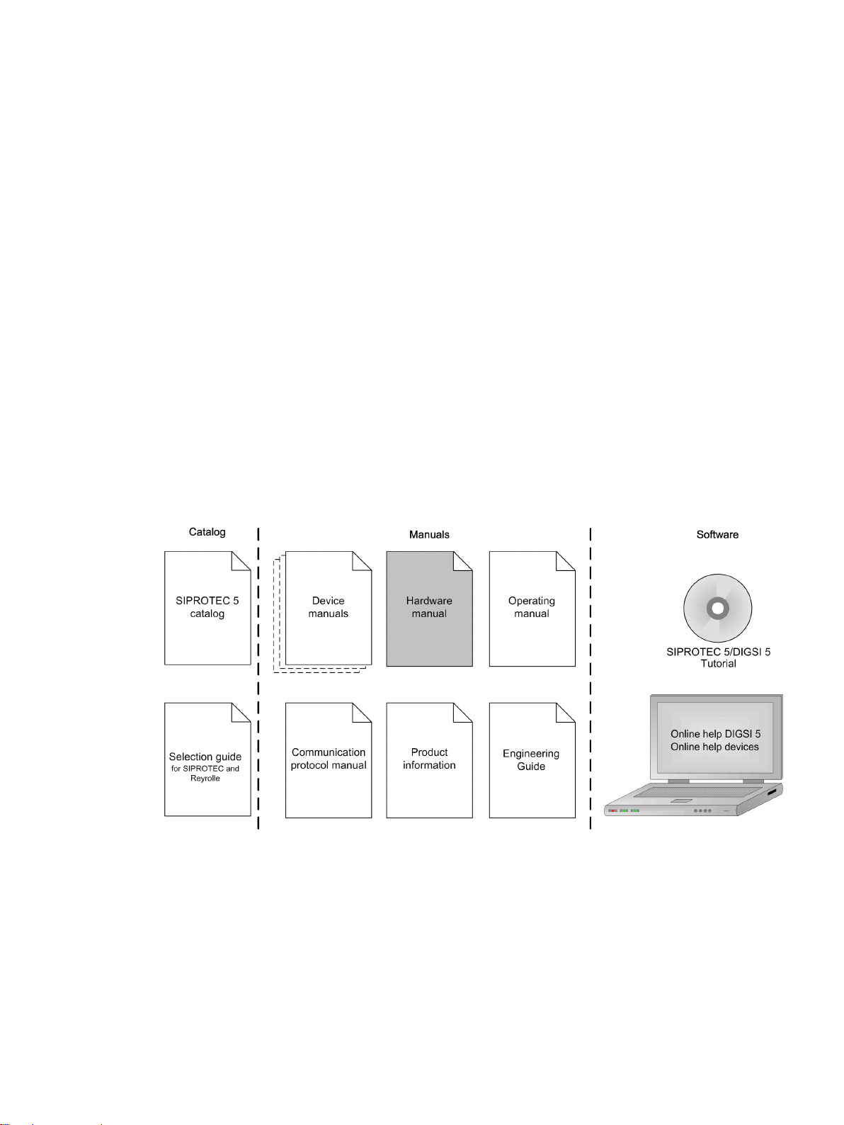
Further Documentation
[dwprefhw-221012-01.tif, 3, en_US]
Device manuals
•
Each Device manual describes the functions and applications of a specific SIPROTEC 5 device. The printed
manual and the online help for the device have the same informational structure.
Hardware manual
•
The Hardware manual describes the hardware building blocks and device combinations of the SIPROTEC 5
device family.
Operating manual
•
The Operating manual describes the basic principles and procedures for operating and assembling the
devices of the SIPROTEC 5 range.
SIPROTEC 5, Hardware Description, Manual
C53000-G5040-C002-C, Edition 10.2017
3

IND. CONT. EQ.
69CA
Preface
Communication protocol manual
•
The Communication protocol manual contains a description of the protocols for communication within
the SIPROTEC 5 device family and to higher-level network control centers.
Product information
•
The Product information includes general information about device installation, technical data, limiting
values for input and output modules, and conditions when preparing for operation. This document is
provided with each SIPROTEC 5 device.
Engineering Guide
•
The Engineering Guide describes the essential steps when engineering with DIGSI 5. In addition, the Engineering Guide shows you how to load a planned configuration to a SIPROTEC 5 device and update the
functionality of the SIPROTEC 5 device.
DIGSI 5 online help
•
The DIGSI 5 online help contains a help package for DIGSI 5 and CFC.
The help package for DIGSI 5 includes a description of the basic operation of software, the DIGSI princi-
ples and editors. The help package for CFC includes an introduction to CFC programming, basic examples
of working with CFC, and a reference chapter with all the CFC blocks available for the SIPROTEC 5 range.
SIPROTEC 5/DIGSI 5 Tutorial
•
The tutorial on the DVD contains brief information about important product features, more detailed information about the individual technical areas, as well as operating sequences with tasks based on practical
operation and a brief explanation.
SIPROTEC 5 catalog
•
The SIPROTEC 5 catalog describes the system features and the devices of SIPROTEC 5.
Selection guide for SIPROTEC and Reyrolle
•
The selection guide offers an overview of the device series of the Siemens protection devices, and a
device selection table.
Indication of Conformity
Other Standards
IEEE Std C 37.90
The technical data of the product is approved in accordance with UL.
For more information about the UL database, see certified.ul.com
Select Online Certifications Directory and enter E194016 as UL File Number.
This product complies with the directive of the Council of the European Communities
on harmonization of the laws of the Member States relating to electromagnetic
compatibility (EMC Directive 2014/30/EU) and concerning electrical equipment for use
within specified voltage limits (Low Voltage Directive 2014/35/EU).
This conformity has been proved by tests performed according to the Council Directive
in accordance with the product standard EN 60255-26 (for EMC directive) and with the
product standard EN 60255-27 (for Low Voltage Directive) by Siemens AG.
The device is designed and manufactured for application in an industrial environment.
The product conforms with the international standards of IEC 60255 and the German
standard VDE 0435.
[ul_listed_c_us, 1, --_--]
4 SIPROTEC 5, Hardware Description, Manual
C53000-G5040-C002-C, Edition 10.2017

Additional Support
!
!
!
For questions about the system, please contact your Siemens sales partner.
Support
Our Customer Support Center provides a 24-hour service.
Phone: +49 (180) 524-7000
Fax: +49 (180) 524-2471
E-Mail: support.energy@siemens.com
Training Courses
Inquiries regarding individual training courses should be addressed to our Training Center:
Siemens AG
Siemens Power Academy TD
Humboldtstraße 59
90459 Nürnberg
Germany
Phone: +49 (911) 433-7415
Fax: +49 (911) 433-7929
E-Mail: poweracademy@siemens.com
Internet: www.siemens.com/poweracademy
Preface
Notes on Safety
This document is not a complete index of all safety measures required for operation of the equipment (module
or device). However, it comprises important information that must be followed for personal safety, as well as
to avoid material damage. Information is highlighted and illustrated as follows according to the degree of
danger:
DANGER
DANGER means that death or severe injury will result if the measures specified are not taken.
²
WARNING
WARNING means that death or severe injury may result if the measures specified are not taken.
²
CAUTION
Comply with all instructions, in order to avoid death or severe injuries.
Comply with all instructions, in order to avoid death or severe injuries.
CAUTION means that medium-severe or slight injuries can occur if the specified measures are not taken.
Comply with all instructions, in order to avoid moderate or minor injuries.
²
SIPROTEC 5, Hardware Description, Manual 5
C53000-G5040-C002-C, Edition 10.2017

i
i
Preface
NOTICE
NOTICE means that property damage can result if the measures specified are not taken.
Comply with all instructions, in order to avoid property damage.
²
NOTE
Important information about the product, product handling or a certain section of the documentation
which must be given particular attention.
Qualified Electrical Engineering Personnel
Only qualified electrical engineering personnel may commission and operate the equipment (module, device)
described in this document. Qualified electrical engineering personnel in the sense of this manual are people
who can demonstrate technical qualifications as electrical technicians. These persons may commission,
isolate, ground and label devices, systems and circuits according to the standards of safety engineering.
Proper Use
The equipment (device, module) may be used only for such applications as set out in the catalogs and the
technical description, and only in combination with third-party equipment recommended and approved by
Siemens.
Problem-free and safe operation of the product depends on the following:
Proper transport
•
Proper storage, setup and installation
•
Proper operation and maintenance
•
When electrical equipment is operated, hazardous voltages are inevitably present in certain parts. If proper
action is not taken, death, severe injury or property damage can result:
The equipment must be grounded at the grounding terminal before any connections are made.
•
All circuit components connected to the power supply may be subject to dangerous voltage.
•
Hazardous voltages may be present in equipment even after the supply voltage has been disconnected
•
(capacitors can still be charged).
Operation of equipment with exposed current-transformer circuits is prohibited. Before disconnecting the
•
equipment, ensure that the current-transformer circuits are short-circuited.
The limiting values stated in the document must not be exceeded. This must also be considered during
•
testing and commissioning.
6 SIPROTEC 5, Hardware Description, Manual
C53000-G5040-C002-C, Edition 10.2017

Open Source Software
i
i
The product contains, among other things, Open Source Software developed by third parties. The Open
Source Software used in the product and the license agreements concerning this software can be found in the
Readme_OSS. These Open Source Software files are protected by copyright. Your compliance with those
license conditions will entitle you to use the Open Source Software as foreseen in the relevant license. In the
event of conflicts between Siemens license conditions and the Open Source Software license conditions, the
Open Source Software conditions shall prevail with respect to the Open Source Software portions of the software. The Open Source Software is licensed royalty-free. Insofar as the applicable Open Source Software
License Conditions provide for it you can order the source code of the Open Source Software from your
Siemens sales contact - against payment of the shipping and handling charges - for a period of at least 3 years
since purchase of the Product. We are liable for the Product including the Open Source Software contained in
it pursuant to the license conditions applicable to the Product. Any liability for the Open Source Software
beyond the program flow intended for the Product is explicitly excluded. Furthermore any liability for defects
resulting from modifications to the Open Source Software by you or third parties is excluded. We do not
provide any technical support for the Product if it has been modified.
When using DIGSI 5 in online mode, you are provided with the option to go to the main menu Show open
source software information and read and display the Readme_OSS file containing the original license text
and copyright information.
To do this, the following steps are necessary:
Switch to online mode.
•
Select the device.
•
Select Online in the menu bar.
•
Click Show open source software information.
•
NOTE
To read the Readme_OSS file, a PDF viewer must be installed on the computer.
In order to operate SIPROTEC 5 devices, a valid DIGSI 5 license is required.
SIPROTEC 5, Hardware Description, Manual
C53000-G5040-C002-C, Edition 10.2017
7

8 SIPROTEC 5, Hardware Description, Manual
C53000-G5040-C002-C, Edition 10.2017

Table of Contents
Preface..........................................................................................................................................................3
Open Source Software..................................................................................................................................7
1 Introduction................................................................................................................................................15
1.1 Advantages of SIPROTEC 5 ................................................................................................16
1.2 Modular Systems and Hardware Characteristics................................................................. 17
2 Forms of Devices and On-Site Operation Panels........................................................................................ 19
2.1 Flush-Mounting Devices.................................................................................................... 20
2.1.1 Description ................................................................................................................. 20
2.2 Surface-Mounted Devices with Integrated On-Site Operation Panel....................................28
2.2.1 Description of the Modular Device............................................................................... 28
2.2.2 Description of the Non-Modular Surface-Mounting Device............................................30
2.3 Surface-Mounted Devices with Detached On-Site Operation Panel..................................... 34
2.3.1 Description..................................................................................................................34
2.4 On-Site Operation Panels.................................................................................................. 37
2.4.1 Description..................................................................................................................37
2.4.2 Overview of Operating Elements and Display Elements................................................ 38
3 Electronic Modules..................................................................................................................................... 43
3.1 Power-Supply Modules of the Modular Devices..................................................................44
3.1.1 Application Sheet of the Power-Supply Modules of the Modular Devices.......................44
3.1.2 Power-Supply Module PS201....................................................................................... 44
3.1.2.1 Description............................................................................................................ 44
3.1.2.2 Terminals...............................................................................................................45
3.1.3 Power-Supply Module PS203....................................................................................... 48
3.1.3.1 Description............................................................................................................ 48
3.1.3.2 Terminals...............................................................................................................49
3.1.4 Plug-In Module Assembly with Integrated Power Supply CB202.................................... 51
3.1.4.1 Description............................................................................................................ 51
3.1.4.2 Terminals...............................................................................................................52
3.2 Input and Output Modules of the Modular Devices............................................................ 54
3.2.1 Function Description of the Input and Output Modules of the Modular Devices.............54
3.2.2 Input and Output Module IO201.................................................................................. 55
3.2.2.1 Description ........................................................................................................... 55
3.2.2.2 Terminals...............................................................................................................55
3.2.3 Input and Output Module IO202.................................................................................. 57
3.2.3.1 Description ........................................................................................................... 57
3.2.3.2 Terminals...............................................................................................................58
3.2.4 Input and Output Module IO203.................................................................................. 60
3.2.4.1 Description ........................................................................................................... 60
3.2.4.2 Terminals...............................................................................................................61
SIPROTEC 5, Hardware Description, Manual 9
C53000-G5040-C002-C, Edition 10.2017

Table of Contents
3.2.5 Input and Output Module IO204.................................................................................. 63
3.2.5.1 Description............................................................................................................ 63
3.2.5.2 Terminals...............................................................................................................64
3.2.6 Input and Output Module IO205.................................................................................. 66
3.2.6.1 Description ........................................................................................................... 66
3.2.6.2 Terminals...............................................................................................................67
3.2.7 Input and Output Module IO206.................................................................................. 69
3.2.7.1 Description ........................................................................................................... 69
3.2.7.2 Terminals...............................................................................................................70
3.2.8 Input and Output Module IO207.................................................................................. 72
3.2.8.1 Description ........................................................................................................... 72
3.2.8.2 Terminals...............................................................................................................72
3.2.9 Input and Output Module IO208.................................................................................. 74
3.2.9.1 Description............................................................................................................ 74
3.2.9.2 Terminals...............................................................................................................75
3.2.10 Input and Output Module IO209.................................................................................. 77
3.2.10.1 Description............................................................................................................ 77
3.2.10.2 Terminals...............................................................................................................78
3.2.11 Input and Output Module IO210.................................................................................. 80
3.2.11.1 Description............................................................................................................ 80
3.2.11.2 Terminals...............................................................................................................81
3.2.12 Input and Output Module IO211.................................................................................. 83
3.2.12.1 Description............................................................................................................ 83
3.2.12.2 Terminals...............................................................................................................84
3.2.13 Input and Output Module IO212.................................................................................. 86
3.2.13.1 Description............................................................................................................ 86
3.2.13.2 Terminals...............................................................................................................87
3.2.14 Input and Output Module IO214.................................................................................. 89
3.2.14.1 Description ........................................................................................................... 89
3.2.14.2 Terminals...............................................................................................................90
3.2.15 Input and Output Module IO215.................................................................................. 92
3.2.15.1 Description ........................................................................................................... 92
3.2.15.2 Terminals ..............................................................................................................92
3.2.16 Input Module IO230.................................................................................................... 93
3.2.16.1 Description............................................................................................................ 93
3.2.16.2 Terminals...............................................................................................................93
3.2.17 Input and Output Module IO231.................................................................................. 96
3.2.17.1 Description............................................................................................................ 96
3.2.17.2 Terminals...............................................................................................................96
3.2.18 Input Module IO233.................................................................................................... 98
3.2.18.1 Description............................................................................................................ 98
3.2.18.2 Terminals...............................................................................................................99
3.2.19 Input and Output Module PB201................................................................................101
3.2.19.1 Description.......................................................................................................... 101
3.2.19.2 Terminals.............................................................................................................102
3.3 Power-Supply Module of Non-Modular Devices (7xx82)................................................... 104
3.3.1 Power-Supply Module PS101..................................................................................... 104
3.3.1.1 Description.......................................................................................................... 104
3.3.1.2 Terminals.............................................................................................................105
3.4 Input and Output Modules of the Non-Modular Devices (7xx82)...................................... 108
3.4.1 Function Description of the Input and Output Modules of the Non-Modular Devices... 108
3.4.2 Input and Output Module IO101................................................................................ 108
3.4.2.1 Description.......................................................................................................... 108
10 SIPROTEC 5, Hardware Description, Manual
C53000-G5040-C002-C, Edition 10.2017

Table of Contents
3.4.2.2 Terminals.............................................................................................................109
3.4.3 Input and Output Module IO102................................................................................ 111
3.4.3.1 Description.......................................................................................................... 111
3.4.3.2 Terminals.............................................................................................................112
3.4.4 Input and Output Module IO103................................................................................ 114
3.4.4.1 Description.......................................................................................................... 114
3.4.4.2 Terminals.............................................................................................................115
3.4.5 Input and Output Module IO110................................................................................ 117
3.4.5.1 Description.......................................................................................................... 117
3.4.5.2 Terminals.............................................................................................................118
3.4.6 Input and Output Module IO111................................................................................ 120
3.4.6.1 Description.......................................................................................................... 120
3.4.6.2 Terminals.............................................................................................................121
3.4.6.3 Connections of Temperature Sensors and Cables.................................................. 123
4 Plug-In Modules........................................................................................................................................127
4.1 Function Description of Plug-In Modules of Modular and Non-Modular Devices................ 128
4.2 Communication Modules................................................................................................ 129
4.2.1 Overview...................................................................................................................129
4.2.2 Communication Applications of the Plug-In Modules ................................................. 132
4.2.3 Serial Modules for Short Distances............................................................................. 135
4.2.3.1 Special Features of Serial Electrical Modules ........................................................ 135
4.2.3.2 USART-AB-1EL...................................................................................................... 136
4.2.3.3 USART-AC-2EL......................................................................................................137
4.2.3.4 USART-AD-1FO.....................................................................................................137
4.2.3.5 USART-AE-2FO..................................................................................................... 138
4.2.4 Serial Modules for Long Distances..............................................................................138
4.2.4.1 Application ..........................................................................................................138
4.2.4.2 USART-AF-1LDFO................................................................................................. 139
4.2.4.3 USART-AG-1LDFO.................................................................................................139
4.2.4.4 USART-AH-1LDFO.................................................................................................141
4.2.4.5 USART-AJ-1LDFO..................................................................................................141
4.2.4.6 USART-AK-1LDFO................................................................................................. 142
4.2.4.7 USART-AW-2LDFO................................................................................................ 143
4.2.4.8 USART-AU-2LDFO.................................................................................................143
4.2.4.9 USART-AX-2LDFO................................................................................................. 144
4.2.4.10 USART-AY-2LDFO................................................................................................. 145
4.2.4.11 USART-AV-2LDFO................................................................................................. 146
4.2.5 Ethernet Modules...................................................................................................... 146
4.2.5.1 Operation of Ethernet Modules............................................................................ 146
4.2.5.2 ETH-BA-2EL.......................................................................................................... 148
4.2.5.3 ETH-BB-2FO......................................................................................................... 149
4.3 Measuring-Transducer Modules.......................................................................................150
4.3.1 Overview...................................................................................................................150
4.3.2 ANAI-CA-4EL..............................................................................................................150
4.3.3 ARC-CD-3FO ............................................................................................................. 151
5 Working on the Device............................................................................................................................. 153
5.1 First Steps....................................................................................................................... 154
5.1.1 Electrical Inspection...................................................................................................154
5.2 Expanding Modular Devices............................................................................................ 156
5.2.1 Flush-Mounting Devices............................................................................................ 156
5.2.1.1 Basic Rules for Expansion..................................................................................... 156
5.2.1.2 Expanding 1st Device Row....................................................................................157
SIPROTEC 5, Hardware Description, Manual 11
C53000-G5040-C002-C, Edition 10.2017

Table of Contents
5.2.1.3 Expanding Devices with 2nd Device Row.............................................................. 158
5.2.2 Surface-Mounted Devices with Integrated On-Site Operation Panel............................ 160
5.2.2.1 Basic Rules for Expansion..................................................................................... 160
5.2.2.2 Expanding 1st Device Row....................................................................................161
5.2.2.3 Expanding Devices with 2nd Device Row.............................................................. 163
5.2.3 Surface-Mounted Devices with Detached On-Site Operation Panel..............................165
5.2.3.1 Basic Rules for Expansion..................................................................................... 165
5.2.3.2 Expanding 1st Device Row ...................................................................................166
5.3 Plug-In Modules.............................................................................................................. 168
5.3.1 Fasteners...................................................................................................................168
5.3.2 Installation................................................................................................................ 168
5.3.3 Removing ................................................................................................................. 169
5.3.4 Replacement............................................................................................................. 171
5.4 Arc Sensors for Module: ARC-CD-3FO...............................................................................173
5.4.1 Point Sensor.............................................................................................................. 173
5.4.1.1 Description ......................................................................................................... 173
5.4.1.2 Installation ..........................................................................................................174
5.4.2 Line Sensor................................................................................................................176
5.4.2.1 Description ......................................................................................................... 176
5.4.2.2 Installation ..........................................................................................................176
5.5 Battery............................................................................................................................179
5.5.1 Description................................................................................................................179
5.5.2 Replacing the Battery ................................................................................................180
5.6 SDHC Memory Card ........................................................................................................181
5.7 Installing Current and Voltage Terminals......................................................................... 183
5.7.1 Description ............................................................................................................... 183
5.7.2 Connections of Current Terminals ............................................................................. 185
5.7.3 Connections of Voltage Terminals..............................................................................187
5.7.3.1 Connections of Voltage Terminals with Spring Clips ............................................. 187
5.7.3.2 Connections of Voltage Terminals with Screw Connection.................................... 188
5.7.4 Installation and Removal............................................................................................188
6 Technical Data.......................................................................................................................................... 189
6.1 Analog Inputs................................................................................................................. 190
6.2 Supply Voltage................................................................................................................193
6.3 Binary Inputs...................................................................................................................195
6.4 Relay Outputs................................................................................................................. 196
6.5 Light-Emitting Diodes in the On-Site Operation Panel.......................................................198
6.6 Communication Interfaces.............................................................................................. 199
6.7 Electrical Tests................................................................................................................ 202
6.8 Mechanical Tests.............................................................................................................205
6.9 Environmental Conditions............................................................................................... 206
6.10 Operating Conditions...................................................................................................... 208
6.11 Reference Conditions and Influencing Variables...............................................................209
6.12 Approvals....................................................................................................................... 210
6.13 Design Data.................................................................................................................... 211
6.14 Assembly Dimensions..................................................................................................... 214
6.15 Modular Device Name Plate.............................................................................................235
12 SIPROTEC 5, Hardware Description, Manual
C53000-G5040-C002-C, Edition 10.2017

Table of Contents
6.16 Name Plate of Non-Modular Devices (7xx82)................................................................... 236
6.17 Name Plate, UL Approval, Base Module and 1/3 Base Module........................................... 237
6.18 Name Plate, UL Approval, Expansion Module................................................................... 238
6.19 Battery ...........................................................................................................................239
6.20 SDHC Memory Card ........................................................................................................240
6.21 Display Resolution ..........................................................................................................241
7 Ordering Information............................................................................................................................... 243
7.1 Ordering Spare Parts and Accessories.............................................................................. 244
7.1.1 Order Configurator and Order Options....................................................................... 244
7.1.2 Ordering Accessories................................................................................................. 244
A Appendix.................................................................................................................................................. 247
A.1 Hardware/Firmware Compatibility List............................................................................. 248
Glossary.................................................................................................................................................... 251
Index.........................................................................................................................................................253
SIPROTEC 5, Hardware Description, Manual 13
C53000-G5040-C002-C, Edition 10.2017

14 SIPROTEC 5, Hardware Description, Manual
C53000-G5040-C002-C, Edition 10.2017

1
Introduction
1.1 Advantages of SIPROTEC 5 16
1.2 Modular Systems and Hardware Characteristics 17
SIPROTEC 5, Hardware Description, Manual 15
C53000-G5040-C002-C, Edition 10.2017

i
i
Introduction
1.1 Advantages of SIPROTEC 5
1.1
Advantages of SIPROTEC 5
The devices in the SIPROTEC 5 series are based on the many years of experience gathered with SIPROTEC 4.
Extensive improvements have also been integrated. Take note of the differences between the modular and
non-modular systems.
The SIPROTEC 5 series is based on a newly developed, flexible modular system that is applicable to all the
devices. This results in the following advantageous new features:
You save time because of jumperless devices.
•
You can set the rated current ranges (1 A, 5 A) electronically. You do not need to open the devices to do
this. You can set the thresholds of the binary inputs by setting parameters.
The freely configurable, modular device design creates more flexibility.
•
You can configure your own device variants in addition to the standard variants. The modular system
consists of base and expansion modules, and optional plug-in modules. Thus, you can combine the
devices exactly as desired, and the standard variants are expandable. Devices with a size of up to 2-row
19-inches are possible.
You save time because of prewired terminal blocks.
•
The terminal blocks for connection of the relays, of the binary inputs and outputs and of the current and
voltage transformers can be removed and fitted again while wired. This enables the possibility of prewiring in the cabinet construction phase. Device replacement is uncomplicated and is possible in a short
time.
You do not need to open the device to install and replace plug-in modules.
•
The slots for the plug-in modules are externally accessible. Communication modules and measuringtransducer modules (for example, 4 x 20-mA measuring-transducer input) can be plugged in at these
plug-in module positions.
Operation is uncomplicated and intuitive.
•
For all modular devices, it is possible to select whether to use a large graphical display, a small display, or
no display. The non-modular devices are available with large or small graphical display. The key switches
on the expansion module can be selected optionally. The 9 function keys enable a safe and uncomplicated procedure for important operator actions.
Multi-colored LEDs ensure safe system management.
•
The 16 LEDs on the base module are 2-colored (green/red). Thus, the status of a signal (OK/disrupted)
can be shown clearly, for example. There can also be 16 red LEDs on each expansion module.
Up to 40 analog channels per device create a greater scope of functions than in SIPROTEC 4.
•
Thus, even complex applications such as the 1 1/2 circuit-breaker layout are possible.
NOTE
For the central busbar protection 7SS85, up to 80 analog channels are possible.
16 SIPROTEC 5, Hardware Description, Manual
C53000-G5040-C002-C, Edition 10.2017

Introduction
1.2 Modular Systems and Hardware Characteristics
1.2
Modular System for Modular Devices
Modular Systems and Hardware Characteristics
The SIPROTEC 5 series includes both modular and non-modular devices.
Modular devices consist of a base module (1/3 of 19 inches) and can be expanded with expansion modules
(1/6 of 19 inches). The device type identifier for modular devices is XXX85, XXX86, or XXX87, for example,
7SA86.
Type xxx84 devices have the same hardware properties as the modular devices, but they cannot be expanded
with expansion modules.
All non-modular devices consist of just a base module (1/3 of 19 inches) and cannot be expanded with expansion modules (1/6 of 19 inches). The device type identifier for non-modular devices is 7XX82, for example,
7SJ82.
The system is based on a modular structure. A modular device always consists of a base module and optionally
of expansion modules. The modules can be selected according to hardware characteristics. These characteristics are:
Module size
•
Type of construction
•
Fastening of the on-site operation panel
•
Creation of the on-site operation panel
•
Input and output module
•
Plug-in modules
•
The modules are available in 2 sizes:
Base module (1/3 of 19 inches)
•
Expansion module (1/6 of 19 inches)
•
The devices are available in 3 designs: These are:
Flush-mounting devices with on-site operation panel fitted directly on the device
•
Surface-mounted devices with integrated on-site operation panel
•
Surface-mounted devices with detached on-site operation panel
•
The on-site operation panels of the base modules can be selected from 3 variants:
With a large display, keypad, and 16 two-colored LEDs
•
With a small display, keypad, and 16 two-colored LEDs
•
Without a display, without a keypad (standard), but with 16 two-colored LEDs
•
The on-site operation panels of the expansion modules can be selected from 3 variants:
With 16 monochrome LEDs and 2 key switches
•
With 16 monochrome LEDs
•
With 8 LEDs and 8 function keys
•
Without display elements
•
The base modules always contain the power-supply module PS201 and an input and output module IO2XX.
The expansion modules contain an input and output module IO2XX or a plug-in module assembly with inte-
grated power supply CB202. The 1st expansion module in the 2nd device row always contains the powersupply module PS203.
The plug-in modules are available for various applications. Plug-in modules can be installed in 1 base module
or in 1 expansion module with 1 plug-in module assembly with integrated power supply CB202. You can find
more information on the available plug-in module types in chapter 4 Plug-In Modules.
SIPROTEC 5, Hardware Description, Manual 17
C53000-G5040-C002-C, Edition 10.2017

Introduction
1.2 Modular Systems and Hardware Characteristics
Hardware Characteristics of Non-Modular Devices (7xx82)
A non-modular device always consists of just 1 module (1/3 of 19 inches) and cannot be expanded with
expansion modules (1/6 of 19 inches). These hardware characteristics are:
Module size: 1/3 of 19 in.
•
Type of construction: Flush-mounting devices with on-site operation panel fitted directly on the device
•
The on-site operation panels can be selected from 2 variants:
With a large display, keypad, and 16 two-colored LEDs
•
With a small display, keypad, and 16 two-colored LEDs
•
The module always contains the power-supply module PS101 and an input and output module IO10X. The
input and output module IO10X includes the terminals for current and voltage transformers. Optionally, the
module can be equipped an additional input and output module IO110 for extra binary inputs and outputs.
The plug-in modules are available for various applications. You can find more information on the available
plug-in module types in chapter 4 Plug-In Modules.
18 SIPROTEC 5, Hardware Description, Manual
C53000-G5040-C002-C, Edition 10.2017

2
Forms of Devices and On-Site Operation Panels
2.1 Flush-Mounting Devices 20
2.2 Surface-Mounted Devices with Integrated On-Site Operation Panel 28
2.3 Surface-Mounted Devices with Detached On-Site Operation Panel 34
2.4 On-Site Operation Panels 37
SIPROTEC 5, Hardware Description, Manual 19
C53000-G5040-C002-C, Edition 10.2017
Forms of Devices and On-Site Operation Panels
2.1 Flush-Mounting Devices
2.1
2.1.1
Base Module
Flush-Mounting Devices
Description
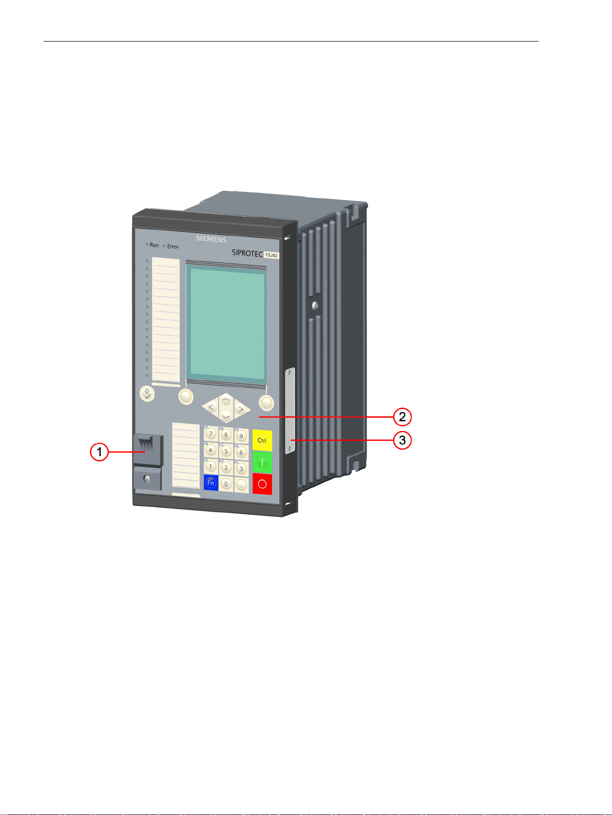
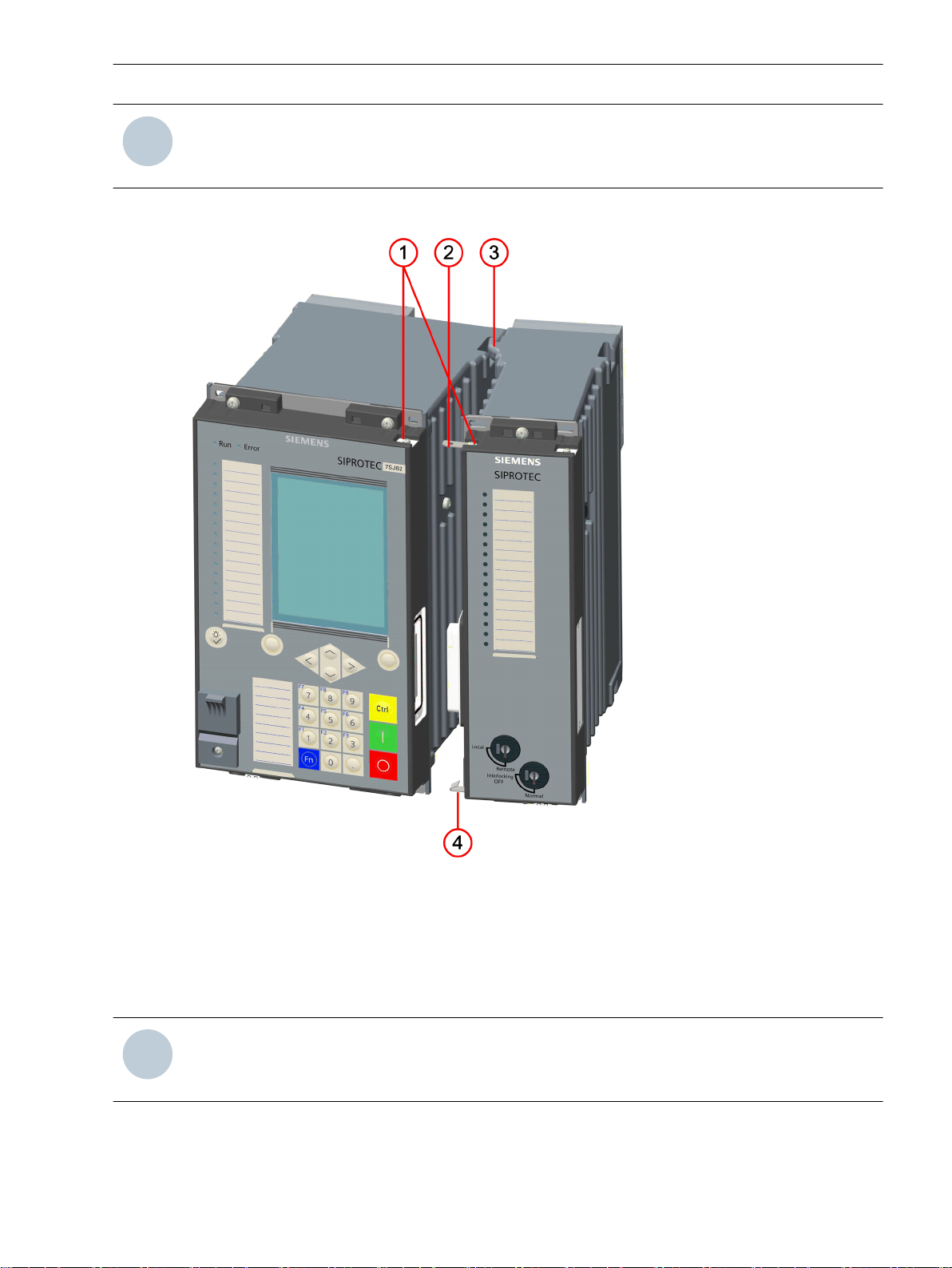
The flush-mounting devices were conceived for installation in 19-inch racks or special openings in control
desks and cabinets. The on-site operation panel is linked permanently to the device.
[le_surface_mounting_front, 2, --_--]
Figure 2-1
(1) USB connection type B
(2) On-site operation panel
(3) Bus terminal for expansion module, only possible for modular devices
20 SIPROTEC 5, Hardware Description, Manual
Front View
C53000-G5040-C002-C, Edition 10.2017
Forms of Devices and On-Site Operation Panels
2.1 Flush-Mounting Devices
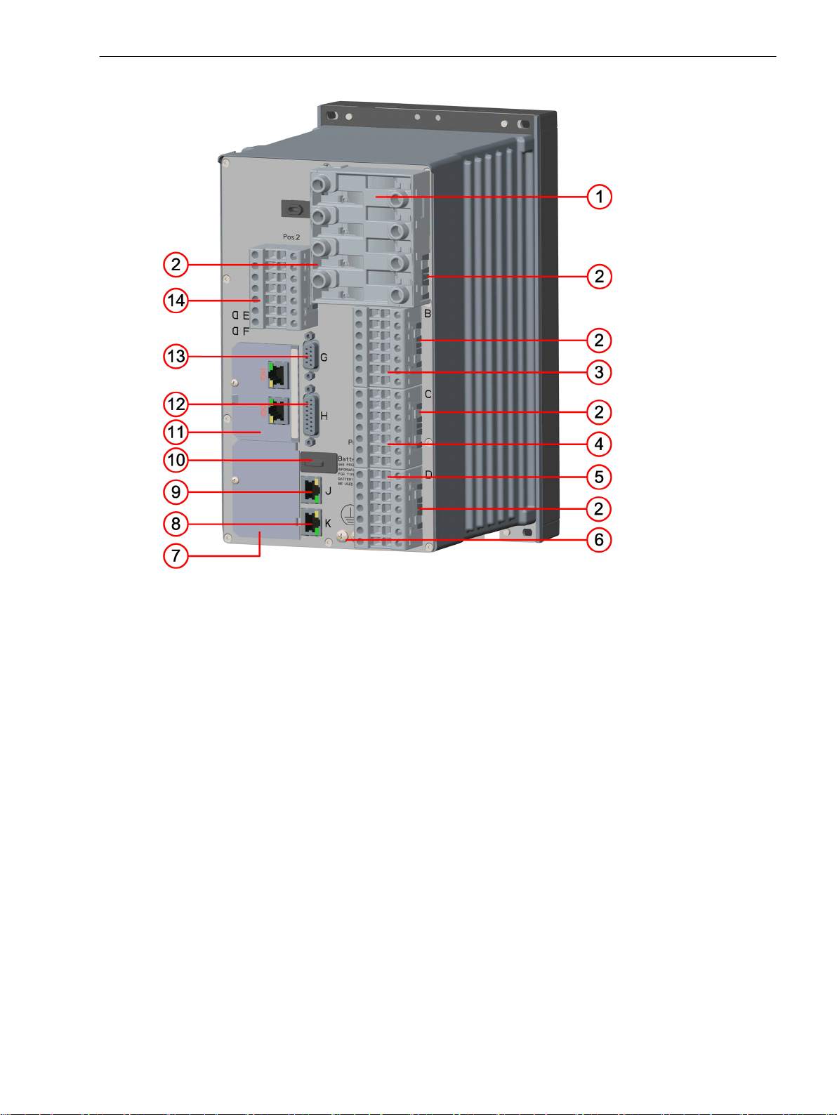
[le_rear modular device, 1, --_--]
Figure 2-2
Rear View of a Modular Device, Terminals of a Typical Device with IO202
(1) Current terminal 1A
(2) Spring clip
(3) Voltage terminal 1B
(4) Voltage terminal 1C
(5) Voltage terminal 1D
(6) Protective grounding terminal
(7) Plug-in module position F
(8) Terminal for COM link K
(9) Terminal for integrated Ethernet interface J
(10) Battery compartment
(11) Plug-in module position E
(12) Terminal for detached on-site operation panel H
(13) Terminal for time synchronization G
(14) Voltage terminal 2B
SIPROTEC 5, Hardware Description, Manual 21
C53000-G5040-C002-C, Edition 10.2017
Forms of Devices and On-Site Operation Panels
2.1 Flush-Mounting Devices
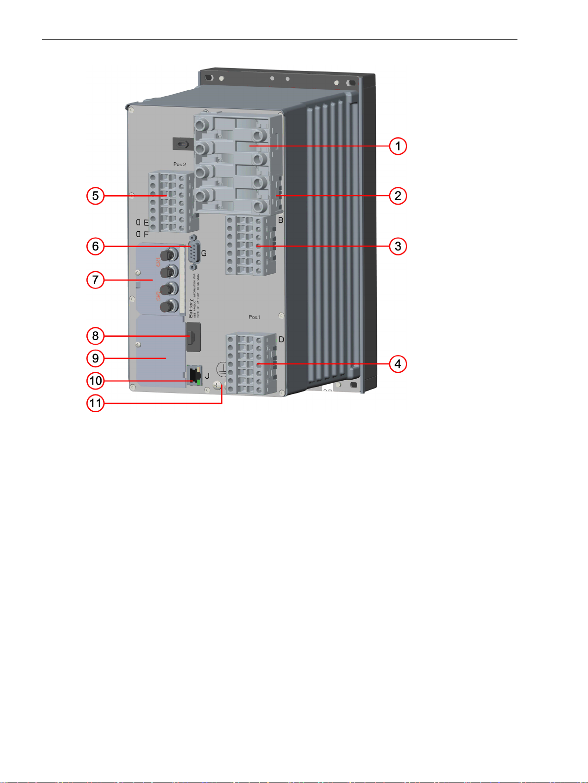
[le_rear non modular, 1, --_--]
Figure 2-3
Rear View of a Non-Modular Device (7xx82), Terminals of a Typical Device with IO102
(1) Current terminal A
(2) Spring clip
(3) Voltage terminal B
(4) Voltage terminal D
(5) Voltage terminal L
(6) Time synchronization G
(7) Plug-in module position E
(8) Battery compartment
(9) Plug-in module position F
(10) Terminal for integrated Ethernet interface J
(11) Protective grounding terminal
22 SIPROTEC 5, Hardware Description, Manual
C53000-G5040-C002-C, Edition 10.2017
Fastening Openings of the Base and 1/3 Module
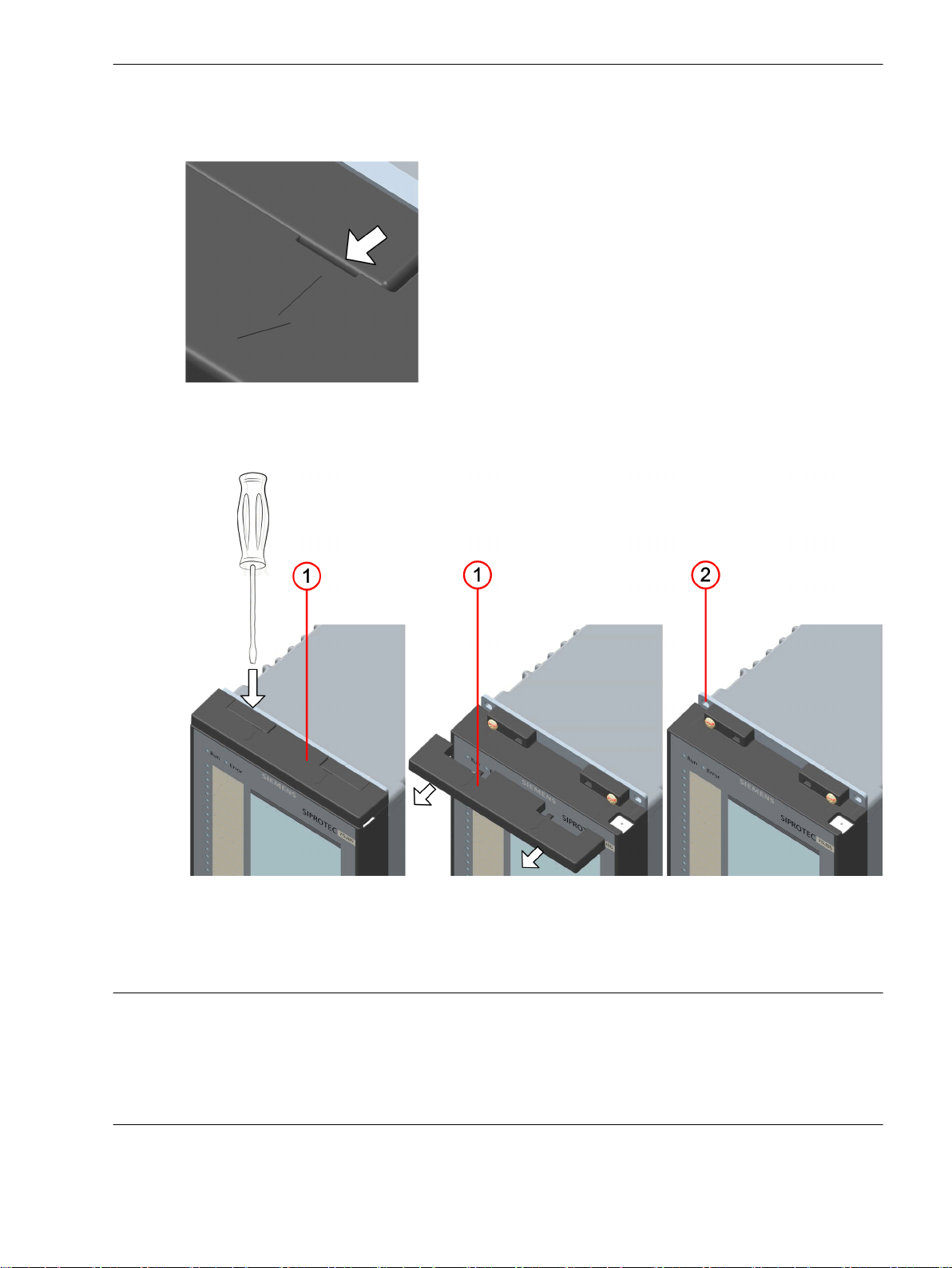
To remove the screw covers, introduce the screwdriver into the provided slot.
[dw_screwdriver, 1, --_--]
Figure 2-4 Slot for Introducing the Screwdriver
Loosen the cover by turning slightly. Then, pull the cover towards you.
Forms of Devices and On-Site Operation Panels
2.1 Flush-Mounting Devices
[le_osobep, 1, --_--]
Figure 2-5
Fastening Openings of the Base and 1/3 Module Shown, for Example, on the Top Fastening
(1) Screw cover
(2) Fastening opening
NOTICE
The screw cover can be damaged if it is removed in an incorrect way.
Non-observance of the following measure can result in material damage.
Use a screwdriver to remove the screw cover.
²
SIPROTEC 5, Hardware Description, Manual 23
C53000-G5040-C002-C, Edition 10.2017
Forms of Devices and On-Site Operation Panels
2.1 Flush-Mounting Devices
Expansion Module
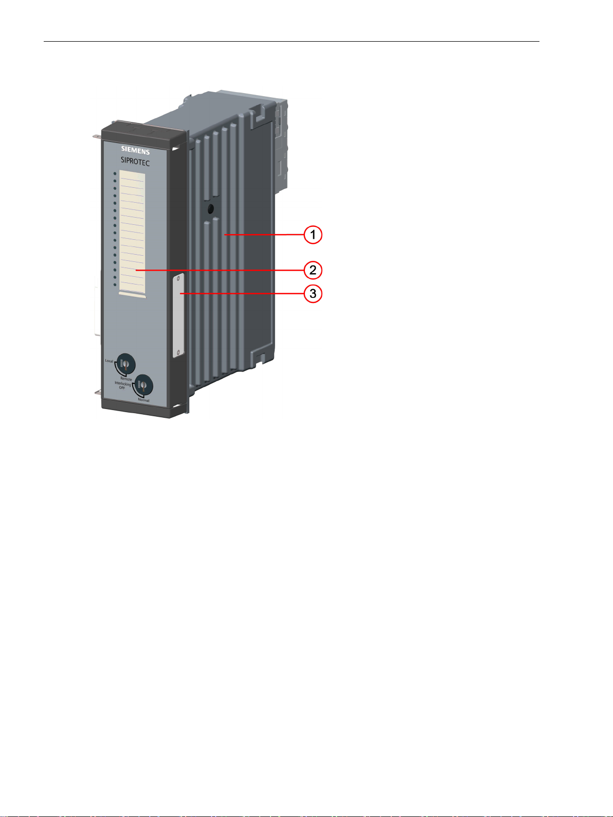
[le_front expansion module, 1, --_--]
Figure 2-6
Front View of the Expansion Module
(1) Device housing
(2) On-site operation panel
(3) Bus terminal for an additional expansion module (shown with bus termination plate)
Unused bus terminals are sealed with a cover.
24 SIPROTEC 5, Hardware Description, Manual
C53000-G5040-C002-C, Edition 10.2017
i
i
Forms of Devices and On-Site Operation Panels
2.1 Flush-Mounting Devices
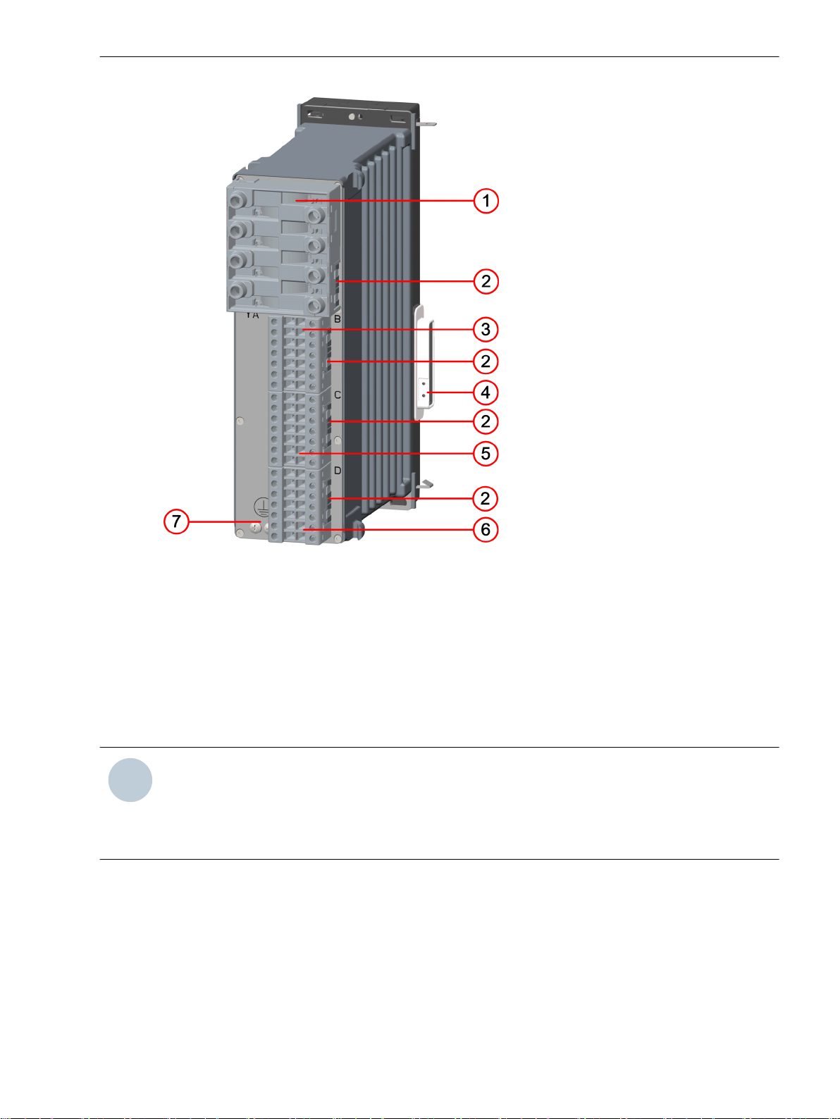
[le_rear expansion module, 1, --_--]
Figure 2-7
(1) Current terminal xA
(2) Spring clip
(3) Voltage terminal xB
(4) Bus terminal to the base module
(5) Voltage terminal xC
(6) Voltage terminal xD
(7) Protective grounding terminal
NOTE
These modules can be installed in the 1st and 2nd device rows. x corresponds to the slot in the 19-inch
rack.
Possible values in the 1st device row: x = 3, 4, 5, or 6
Possible values in the 2nd device row: x = 8, 9, 10, 11 or 12
Rear View of the Expansion Module
SIPROTEC 5, Hardware Description, Manual 25
C53000-G5040-C002-C, Edition 10.2017
Forms of Devices and On-Site Operation Panels
2.1 Flush-Mounting Devices
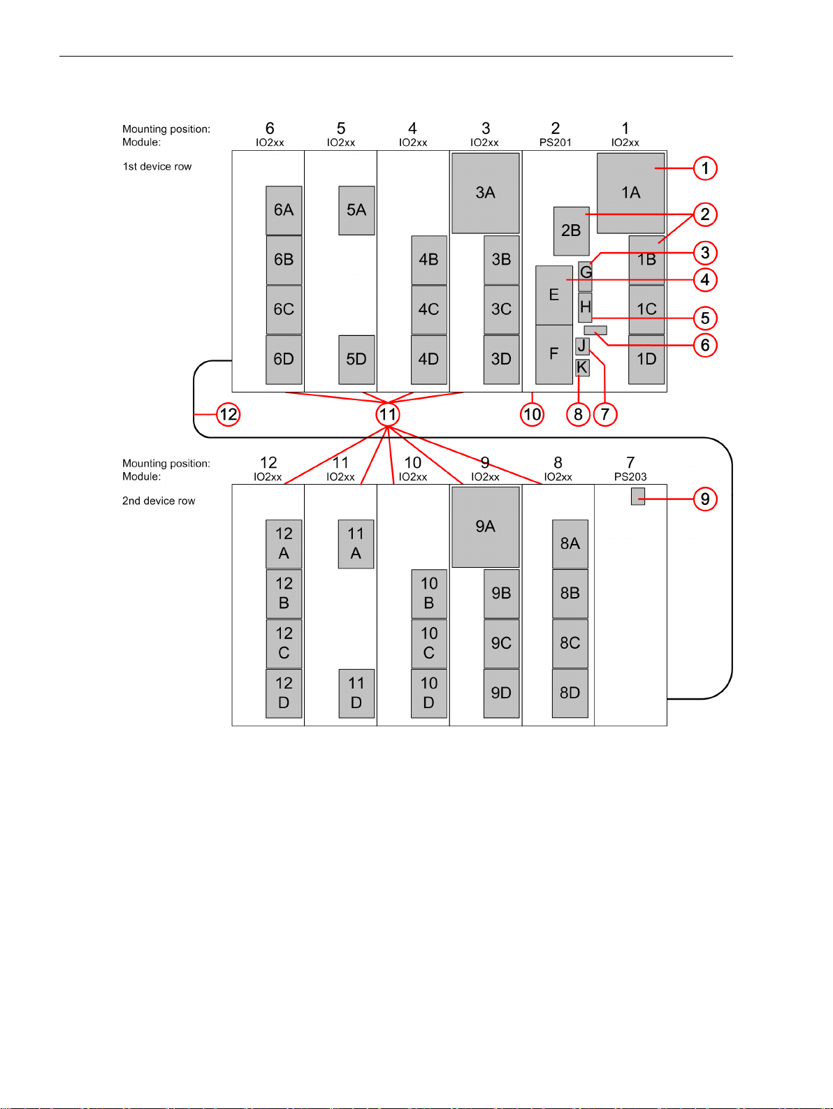
Counting Method for Assemblies in 19-Inch Rack (View of the Rear of the Device)
[dwbgrpos-170713-01.tif, 3, en_US]
Figure 2-8
Counting Method for Assemblies in 19-Inch Rack (Example)
(1) Current terminal A
(2) Voltage terminal A, B, C, D
(3) Terminal for time synchronization G
(4) Plug-in module E, F
(5) Terminal for detached on-site operation panel H
(6) Battery compartment
(7) Terminal for integrated Ethernet interface J
(8) Terminal for COM link K
(9) 2-pole terminal to connect power supply
(10) Base module 1/3 of 19 in
(11) Expansion module 1/6 of 19 in
(12) Connecting cable between 1st and 2nd device row
26 SIPROTEC 5, Hardware Description, Manual
C53000-G5040-C002-C, Edition 10.2017
i
i
NOTE
i
i
The structure of the 2nd device row is described in chapter 5.2.1.3 Expanding Devices with 2nd Device
Row.
Connection Systems
Forms of Devices and On-Site Operation Panels
2.1 Flush-Mounting Devices
[le_connection, 1, --_--]
Figure 2-9
(1) Cut-out for contact tab
(2) Contact tab (prefitted on the expansion module)
(3) Hinged angle clip
(4) Snap-in spring
NOTE
All on-site operation panels must be connected to one another via the bolt-on contact tabs. The contact
tabs are delivered with the expansion modules.
SIPROTEC 5, Hardware Description, Manual 27
C53000-G5040-C002-C, Edition 10.2017
Connection Systems
i
i
Forms of Devices and On-Site Operation Panels
2.2 Surface-Mounted Devices with Integrated On-Site Operation Panel
2.2
2.2.1
Base Module
Surface-Mounted Devices with Integrated On-Site Operation Panel
Description of the Modular Device
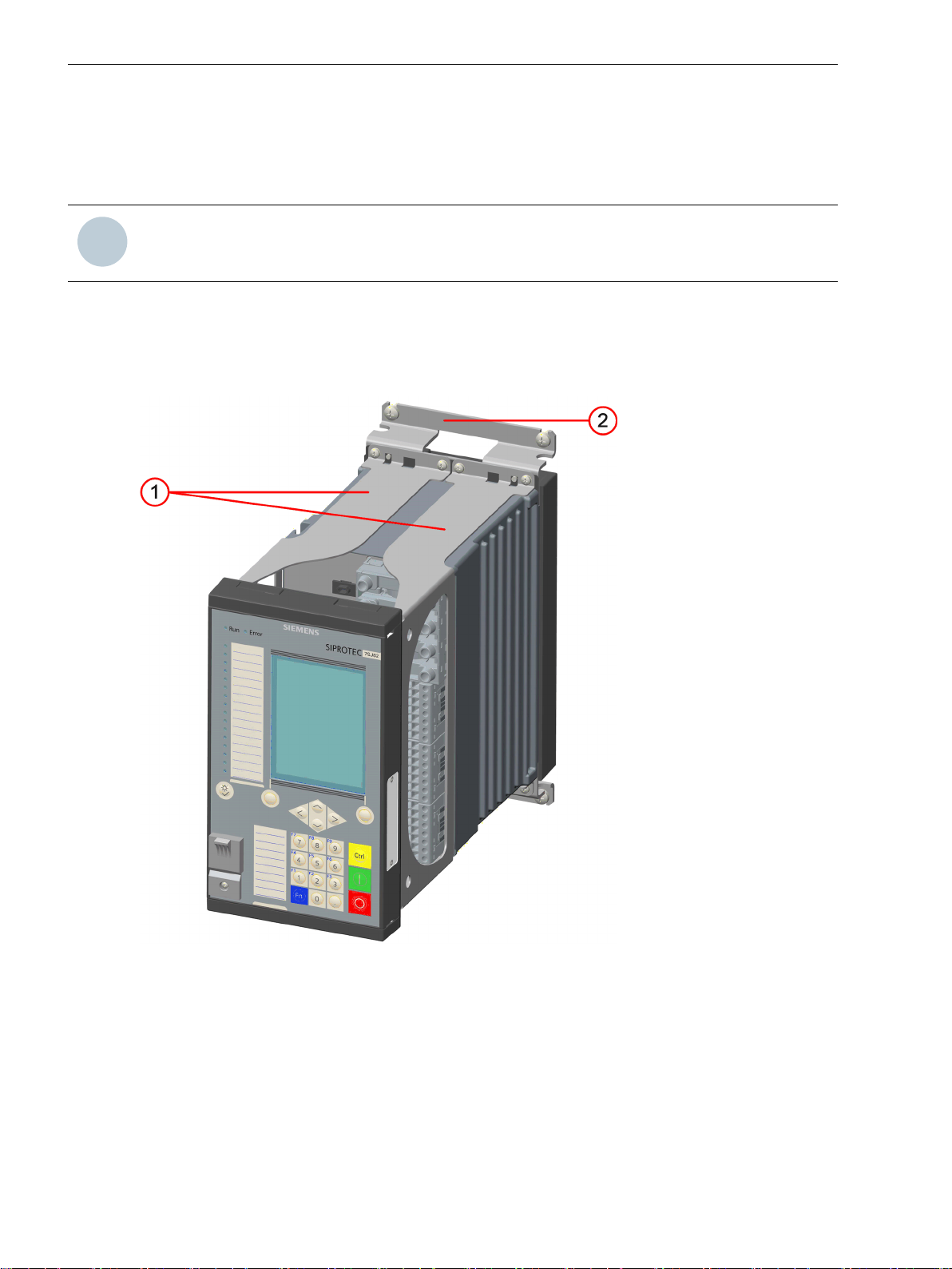
The surface-mounting devices with integrated on-site operation panel were conceived for fitting on a flat wall
surface. The on-site operation panel is fastened on the device with a distance frame. The distance frame
creates the necessary wiring space for the cable connections.
NOTE
The basic device structure is described in chapter 2.1.1 Description .
[le_device mounting, 1, --_--]
Figure 2-10
(1) Outer distance frame
(2) Fixing bracket
28 SIPROTEC 5, Hardware Description, Manual
Device Structure
C53000-G5040-C002-C, Edition 10.2017
i
i
Forms of Devices and On-Site Operation Panels
2.2 Surface-Mounted Devices with Integrated On-Site Operation Panel
[dwauzeil-040211-01.tif, 2, --_--]
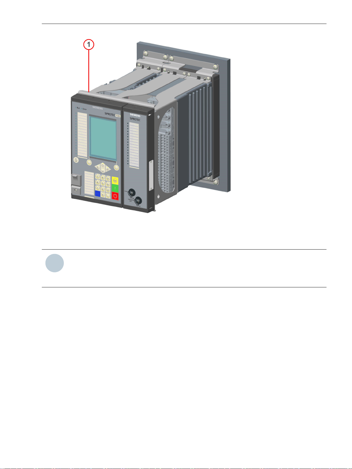
Figure 2-11
(1) Mounting bracket
NOTE
When a base module is expanded, 2 mounting brackets must be fitted between the on-site operation
panels and the distance frame. The mounting bracket stabilizes the device. The length of the mounting
bracket corresponds to the width of the device.
Basic and Expansion Module of the Surface-Mounting Device
SIPROTEC 5, Hardware Description, Manual 29
C53000-G5040-C002-C, Edition 10.2017
i
i
Forms of Devices and On-Site Operation Panels
2.2 Surface-Mounted Devices with Integrated On-Site Operation Panel
Fastening Openings
[dwbaaube-040211-01.tif, 2, --_--]
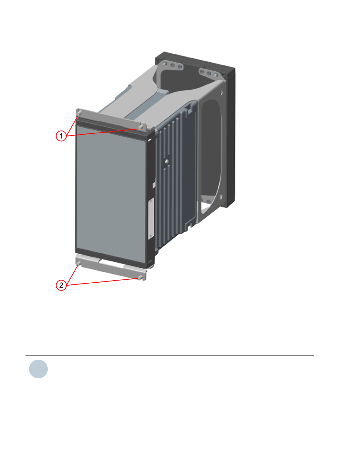
Figure 2-12
(1) Top fastening openings
(2) Bottom fastening openings
2.2.2
30 SIPROTEC 5, Hardware Description, Manual
Description of the Non-Modular Surface-Mounting Device
NOTE
The basic device structure is described in chapter 2.1.1 Description .
The non-modular device variant is designed for mounting to a flat wall surface. This variant is created by flushmounting the non-modular device into the surface-mounting bracket. In this process, you may face the
opening as needed upward (cables coming from above) or downward (cables coming from below) as shown
in the following figure. You can order the surface-mounting bracket individually.
Fastening Openings of the Base Module
C53000-G5040-C002-C, Edition 10.2017

Forms of Devices and On-Site Operation Panels
2.2 Surface-Mounted Devices with Integrated On-Site Operation Panel
[le_device with console above and below, 1, --_--]
Figure 2-13
Bracket with the Opening Upward (Left) and the Opening Downward (Right)
(1) Flush-mounting device
(2) Bracket for the surface-mounting variant
(3) Bracket opening for cable entry or exit when mounting or dismantling the device
SIPROTEC 5, Hardware Description, Manual 31
C53000-G5040-C002-C, Edition 10.2017

Forms of Devices and On-Site Operation Panels
2.2 Surface-Mounted Devices with Integrated On-Site Operation Panel
[sc device mounting, 2, --_--]
Figure 2-14
Surface-Mounting Version of the Non-Modular Device, Mounted
32 SIPROTEC 5, Hardware Description, Manual
C53000-G5040-C002-C, Edition 10.2017

Fastening Openings
Forms of Devices and On-Site Operation Panels
2.2 Surface-Mounted Devices with Integrated On-Site Operation Panel
[sc fixing console, 2, --_--]
Figure 2-15
Fastening Openings of the Bracket
SIPROTEC 5, Hardware Description, Manual 33
C53000-G5040-C002-C, Edition 10.2017

i
i
Forms of Devices and On-Site Operation Panels
2.3 Surface-Mounted Devices with Detached On-Site Operation Panel
2.3
2.3.1
Base Module
Surface-Mounted Devices with Detached On-Site Operation Panel
Description
The surface-mounting devices with detached on-site operation panel are a variant of the surface-mounting
devices with an integrated on-site operation panel. The essential difference is that you can fit the on-site operation panel separately from the device. The distance frames are not assembled in this device type.
The distance between the installation location of the device and that of the on-site operation panel is limited
to not more than 5 m (196.85 in) by the length of the connecting cable. The on-site operation panel must be
grounded.
NOTE
The basic device structure is described in chapter 2.1.1 Description .
[le_device mounting base module, 1, --_--]
Figure 2-16
(1) Top fixing bracket
(2) Cover
(3) Bottom fixing bracket
34 SIPROTEC 5, Hardware Description, Manual
Device Structure of the Base Module
C53000-G5040-C002-C, Edition 10.2017

(4) Rear plate of the on-site operation panel
(5) Connecting cable between the base module and the on-site operation panel
Fastening Openings
Forms of Devices and On-Site Operation Panels
2.3 Surface-Mounted Devices with Detached On-Site Operation Panel
[dwbaaube-040211-01.tif, 2, --_--]
Figure 2-17
Device Structure of the Base Module
(1) Top fastening openings
(2) Bottom fastening openings
SIPROTEC 5, Hardware Description, Manual 35
C53000-G5040-C002-C, Edition 10.2017

Forms of Devices and On-Site Operation Panels
2.3 Surface-Mounted Devices with Detached On-Site Operation Panel
[dwosobb1-040211-01.tif, 2, --_--]
Figure 2-18
Fastening Openings for the On-Site Operation Panel
(1) Screw cover (pull towards you to remove)
(2) Fastening opening
(3) Fastening opening with fastening screw
36 SIPROTEC 5, Hardware Description, Manual
C53000-G5040-C002-C, Edition 10.2017

Forms of Devices and On-Site Operation Panels
2.4 On-Site Operation Panels
2.4
2.4.1
Operating Concept
User Interface Language
On-Site Operation Panels
Description
The operating concept is based on 4 groups:
Navigation in the menu tree
•
Modification of settings
•
Display of measured values and protocols
•
Control function from menu bar or control display
•
Operating personnel are informed about the current state of important measured data, indications, and
parameters. The data can be read out. You can perform parameterization and switching operations directly on
the device.
You can set the user interface language to the following:
Local language
•
US English
•
IEC 61850
•
Variants
Corresponding to the equipment configuration, 3 variants are available for each size. In the case of the nonmodular devices, only the front variants with small and large display are available.
[dwvaosop-080211-01.tif, 3, --_--]
Figure 2-19 Variants 1/3 Views
SIPROTEC 5, Hardware Description, Manual 37
C53000-G5040-C002-C, Edition 10.2017

Forms of Devices and On-Site Operation Panels
2.4 On-Site Operation Panels
[dw_osop_with_pushbutton, 2, --_--]
Figure 2-20 Variants 1/6 Views
2.4.2
Overview of Operating Elements and Display Elements
On-Site Operation Panel of the Base 1/3 Module
[le_base_module, 1, --_--]
Figure 2-21 Base 1/3 Module in Standard, US, and China Design
(1) Operating state display
(2) Display in 2 design versions
(3) Keypad with navigation keys
(4) Softkey
(5) Keypad with numerical keys and shiftable function keys
(6) Keypad of control keys
(7) USB port cover
(8) Cover labels
(9) Reset and LED test key
(10) 16 two-colored LEDs
38 SIPROTEC 5, Hardware Description, Manual
C53000-G5040-C002-C, Edition 10.2017

Forms of Devices and On-Site Operation Panels
2.4 On-Site Operation Panels
The on-site operation panels are distinguished by the following characteristics:
Flat and compact design
•
LCD (Liquid Crystal Display) graphics display
•
Small with 192 x 128 pixels for showing measured values and small control displays
Large with 240 x 320 pixels for showing measured values and control displays
Membrane keypad
•
Menu navigation function keys
•
USB port, type B for notebook/PC
•
16 two-colored LEDs (parameterizable)
•
The operating elements and display elements of the on-site operation panel for base modules are explained in
the following table.
Operating Element/
Display Element
Function
Testing LED functionality and resetting the LEDs to the original state
Softkey for confirming command prompts
On the left and right underneath the display
Keypad with navigation keys for navigating in the menus or in the graphical
displays (control displays)
Keypad with numerical keys for the entry of values and with programmable function keys for fast execution of actions
Next to the keypad there are labeling strips for user-defined labels.
Activating the function keys
Control key for activating the control display
Control key for activating the switching object
Control key for deactivating the switching object
Display of operability
Run: ready to operate, the green LED is lit.
Error: not ready to operate, the red LED is lit.
SIPROTEC 5, Hardware Description, Manual 39
C53000-G5040-C002-C, Edition 10.2017

Forms of Devices and On-Site Operation Panels
2.4 On-Site Operation Panels
Operating Element/
Display Element
On-Site Operation Panel of Expansion Modules
Function
USB port with protective cover
Type B for notebook/PC
16 two-colored parameterizable LEDs
[le_expansion modules, 1, --_--]
Figure 2-22
(1) 16 monochrome LEDs
(2) Cover labels
(3) 2 key switches
(4) 8 monochrome LEDs
(5) 8 push-buttons
The on-site operation panels are distinguished by the following characteristics:
Flat and compact design
•
16 monochrome parameterizable LEDs
•
40 SIPROTEC 5, Hardware Description, Manual
Expansion Module
C53000-G5040-C002-C, Edition 10.2017

Forms of Devices and On-Site Operation Panels
2.4 On-Site Operation Panels
Decorative film
•
2 key switches for setting the operating mode
•
Besides the base module, you can add an expansion module with key switches. The following table explains
the meanings of the switch positions.
Operating Element/
Display Element
The on-site operation panel with push-buttons is equipped with 8 LEDs and 8 function keys. It can be used as
an on-site operation panel by almost all the I/O modules (except for the modules IO230, IO231). The pushbutton module must be placed in the 1st row at position 3. If the device has a key switch, then the pushbutton module must be placed in the 1st row at position 4. One push-button module is permitted per device.
Meaning
16 monochrome parameterizable LEDs
Local: on-site operation
Remote: remote control
Interlocking OFF: unlocked operation
Normal: locked operation with the configured interlocking conditions
Operating Element/
Display Element
Meaning
8 monochrome parameterizable LEDs
Keypad with programmable function keys for fast execution of actions. Next to
the keypad there are labeling strips for user-defined labels.
SIPROTEC 5, Hardware Description, Manual 41
C53000-G5040-C002-C, Edition 10.2017

42 SIPROTEC 5, Hardware Description, Manual
C53000-G5040-C002-C, Edition 10.2017

3
Electronic Modules
3.1 Power-Supply Modules of the Modular Devices 44
3.2 Input and Output Modules of the Modular Devices 54
3.3 Power-Supply Module of Non-Modular Devices (7xx82) 104
3.4 Input and Output Modules of the Non-Modular Devices (7xx82) 108
SIPROTEC 5, Hardware Description, Manual 43
C53000-G5040-C002-C, Edition 10.2017

Electronic Modules
3.1 Power-Supply Modules of the Modular Devices
3.1
3.1.1
3.1.2
3.1.2.1
Power-Supply Modules of the Modular Devices
Application Sheet of the Power-Supply Modules of the Modular Devices
Module Designation Function Description
PS201
PS203
CB202
Power-Supply Module PS201
Description
Power-supply module
•
24 V DC/48 V DC or
•
DC 60 V to DC 250 V and AC 100 V to AC 230 V
In the base module 1/3 of 19 in
•
Assembled with 3 binary inputs, 2 binary outputs, and one status life contact
•
Power-supply module for supplying the 2nd device row
•
24 V DC/48 V DC or
•
DC 60 V to DC 250 V and AC 100 V to AC 230 V
In the expansion module, 1/6 of 19 in
•
Plug-in module assembly with internal power supply
•
24 V DC/48 V DC or
•
DC 60 V to DC 250 V and AC 100 V to AC 230 V
In the expansion module, 1/6 of 19 in
•
The power-supply module PS201 is always permanently installed in the base module. The central task is to
supply power to all modules. The following can be found on the PS201 module:
2 positions for plug-in modules (communication modules, measuring-transducer modules)
•
Terminals for time synchronization, the on-site operation panel, an integrated Ethernet interface, and a
•
COM link interface
A 14-pole voltage terminal (3 binary inputs and 3 binary outputs)
•
Battery for the CPU.
•
The power supply of the other modules is established automatically through the plug-in bus connection when
they are assembled.
The following 2 variants are available for the rated voltage range:
DC 24 V to 48 V
•
DC 60 V to DC 250 V and AC 100 V to AC 230 V (50 Hz and 60 Hz)
•
44 SIPROTEC 5, Hardware Description, Manual
C53000-G5040-C002-C, Edition 10.2017

Electronic Modules
3.1 Power-Supply Modules of the Modular Devices
3.1.2.2
Terminals
Overview of Terminals
[le_ps201, 1, --_--]
Figure 3-1
PS201 – Terminals
(1) Voltage terminal 2B
(2) Time synchronization G
(3) Detached on-site operation panel H
(4) Plug-in module position E
(5) Integrated Ethernet interface J
(6) COM link K, connection to the CB202 PCB assembly (plug-in module assembly), position K
(7) Plug-in module position F
(8) Protective grounding terminal
SIPROTEC 5, Hardware Description, Manual 45
C53000-G5040-C002-C, Edition 10.2017

Electronic Modules
3.1 Power-Supply Modules of the Modular Devices
Terminal and Connection Diagram
[cdps201x-270912-01.tif, 1, en_US]
Figure 3-2 PS201 – Terminal Diagram
46 SIPROTEC 5, Hardware Description, Manual
C53000-G5040-C002-C, Edition 10.2017

Electronic Modules
3.1 Power-Supply Modules of the Modular Devices
[tdps201x-270812-01.tif, 1, en_US]
Figure 3-3
PS201 – Connection Diagram
Time-Synchronization Terminal
The terminal for time synchronization is located on the D-sub 9 interface (position G). Time synchronization
signals for DC 5 V, DC 12 V, and DC 24 V can be processed as an option.
For further information on connecting to the time synchronization, see chapter 6.6 Communication Interfaces
in the Technical Data.
On-Site Operation Panel Terminal
The terminal for the on-site operation panel of surface-mounted devices is located on the D-sub 15 interface
(position H). The on-site operation panel of surface-mounted devices with the on-site operation panel integrated or detached is connected to this interface.
For further information on connecting to the on-site operation panel, see chapter 6.6 Communication Inter-
faces in the Technical Data.
Integrated Ethernet Interface J (RJ45)
This terminal is used to load the device with DIGSI 5 using Ethernet. This terminal also enables straightforward
IEC 61850 Ethernet communication or communication with another protocol via Ethernet, for example, for
connecting an external RTD unit.
For further information on the integrated Ethernet interface, see chapter 6.6 Communication Interfaces in the
Technical Data.
SIPROTEC 5, Hardware Description, Manual 47
C53000-G5040-C002-C, Edition 10.2017

i
i
Electronic Modules
3.1 Power-Supply Modules of the Modular Devices
Ethernet COM Link
The Ethernet connection to the CB202 PCB assembly (plug-in module assembly with integrated power supply)
is realized using the RJ45 interface.
The RJ45 interface can be used exclusively for the connection of the CB202 module. This terminal is left
unused when no CB202 module is in use.
For further information on the Ethernet COM link, see chapter 6.6 Communication Interfaces in the Technical
Data.
3.1.3
3.1.3.1
Power-Supply Module PS203
Description
If you expand the device into the 2nd device row, you need the PS203 power-supply module.
NOTE
The PS203 power-supply module is always supplied with the expansion module and must always be
mounted at position 7.
Up to 5 additional expansion modules are possible in the 2nd device row. The scope of delivery of the PS203
power-supply module includes 1 connecting cable for the 2nd device row, 1 angle rail, 1 sealing panel and 1
adaptor bracket.
The PS203 power-supply module has no additional functionality. It is used exclusively to supply power to the
2nd device row.
The rated voltage variant of the PS203 power-supply module must always match the PS201 power-supply
module of the base module.
48 SIPROTEC 5, Hardware Description, Manual
C53000-G5040-C002-C, Edition 10.2017

Electronic Modules
3.1 Power-Supply Modules of the Modular Devices
3.1.3.2
Terminals
Overview of Terminals
[le_ps203, 1, --_--]
Figure 3-4
(1) 2-pole terminal to connect power supply
(2) LED: Power On
(3) Protective grounding terminal
Connection Diagram
[tdps203x-030713-01.tif, 2, en_US]
Figure 3-5 PS203 – Connection Diagram
PS203 – Terminals
SIPROTEC 5, Hardware Description, Manual 49
C53000-G5040-C002-C, Edition 10.2017

i
i
Electronic Modules
3.1 Power-Supply Modules of the Modular Devices
[dwkl2pol-030211-01.tif, 1, --_--]
Figure 3-6 Connection of External Power Supply
NOTE
When expanding a device with the 2nd device row, you must install the connecting cable for the 2nd
device row together with the associated angle rail. All required components are included with a powersupply module PS203.
[dw_kabel1-020414-01, 1, --_--]
Figure 3-7 Connecting Cable for the Connection of a 2nd Device Row
(1) Handle mold for the connection to the 1st device row
(2) Handle mold for the connection to the 2nd device row
[dw_winkel-020414-01, 1, --_--]
Figure 3-8 Sealing Plate and Adaptor Bracket for the Expansion Module of the 1st Device Row
50 SIPROTEC 5, Hardware Description, Manual
C53000-G5040-C002-C, Edition 10.2017

i
i
3.1 Power-Supply Modules of the Modular Devices
(1) Device bus of the outermost right expansion module of the 1st device row
(2) Sealing plate
(3) Adaptor angle
(4) 2 fastening screws
[dw_schiene-020414-01, 1, --_--]
Figure 3-9 Angle Rail
(1) Angle rail
(2) 2 rubber seals
Electronic Modules
3.1.4
3.1.4.1
Plug-In Module Assembly with Integrated Power Supply CB202
Description
The plug-in module assembly CB202 is a module with an internal power supply. The CB202 module is used in
an expansion module. 3 plug-in module positions (M, N and P) are available for installation of plug-in
modules. The plug-in modules can be installed in the following arrangements:
Plug-In Module Position
M N P
Configured with
3 measuring-transducer
modules
Configured with
2 measuring-transducer
modules and
1 communication module
Configured with
1 measuring-transducer
module and
2 communication modules
Combinations that do not occupy all plug-in module positions are also possible.
NOTE
Measuring-transducer
module
Measuring-transducer
module
Measuring-transducer
module
Measuring-transducer
module
Measuring-transducer
module
Measuring-transducer
module
Communication module Measuring-transducer
Communication module Communication module
Measuring-transducer
module
Communication module
module
A communication module cannot be plugged into the plug-in module position M.
The CB202 module communicates with the base module using a communication connection. This communication connection is established with a special connecting cable. This connecting cable (CAT5 FTP patch cable)
is always included in the scope of delivery of the CB202 module and need not be ordered separately.
The following 2 variants are available for the rated voltage range:
DC 24 V to 48 V
•
DC 60 V to DC 250 V and AC 100 V to AC 230 V (50 Hz and 60 Hz)
•
The CB202 PCB assembly assembly can be used in the 1st and 2nd device rows.
SIPROTEC 5, Hardware Description, Manual 51
C53000-G5040-C002-C, Edition 10.2017

Electronic Modules
3.1 Power-Supply Modules of the Modular Devices
LEDs of the RJ45 Terminals
The light-emitting diodes (LEDs) signal the operating state of the communication connection. The operating
states are explained in the following table:
COM Link (RJ45) Signal Color Operating State
LED 1 CL2_LED0_N Yellow Flashes when a communication module is inserted in
LED 2 CL3_LED0_N Green Flashes when a communication module is inserted in
plug-in module position P.
plug-in module position N.
3.1.4.2
Terminals
Overview of Terminals
[dwcb202p-030211-01.tif, 2, --_--]
Figure 3-10
CB202 – Terminals
(1) 2-pole terminal to connect power supply
(2) LED: Power On
(3) COM link
(4) Plug-in module position M (for measuring-transducer modules only – equipped in this example
with an ANAI module)
(5) Plug-in module position N (for measuring-transducer or communication modules)
(6) Plug-in module position P (for measuring-transducer or communication modules – equipped in
this example with an ETH-BA-2EL module)
(7) Protective grounding terminal
The Ethernet connection to the base module is established at the COM link terminal.
The 2-pole voltage terminal is used for the external power supply (see Figure 3-12).
52 SIPROTEC 5, Hardware Description, Manual
C53000-G5040-C002-C, Edition 10.2017

Connection Diagram
[tdcb202x-100713-01.tif, 2, en_US]
Figure 3-11 CB202 – Connection Diagram
Electronic Modules
3.1 Power-Supply Modules of the Modular Devices
[dwkl2pol-030211-01.tif, 1, --_--]
Figure 3-12 Connection of External Power Supply
SIPROTEC 5, Hardware Description, Manual 53
C53000-G5040-C002-C, Edition 10.2017

Electronic Modules
3.2 Input and Output Modules of the Modular Devices
3.2
3.2.1
Input and Output Modules of the Modular Devices
Function Description of the Input and Output Modules of the Modular Devices
Module Designation Function Description
IO201
IO202
IO203
IO204
IO205
IO206
IO207
IO208
IO209
IO210
IO211
IO212
IO214
IO215
IO230
IO231
IO233
PB201
Input and output module
•
4 current measuring inputs, 8 binary inputs, 6 binary outputs
•
Input and output module
•
4 current measuring inputs, 4 voltage measuring inputs, 8 binary inputs,
•
6 binary outputs
Input and output module
•
8 current measuring inputs, 4 binary inputs, 4 binary outputs
•
Input and output module
•
10 binary inputs, 4 binary outputs, 4 power relays for controlling 2 motors
•
Input and output module
•
12 binary inputs, 16 binary outputs
•
Input and output module
•
6 binary inputs, 7 binary outputs
•
Input and output module
•
16 binary inputs, 8 binary outputs
•
Input and output module
•
4 current measuring inputs, 4 voltage measuring inputs, 4 binary inputs,
•
11 binary outputs
Input and output module
•
8 binary inputs, 4 high-speed binary outputs (semiconductor accelerated)
•
Input and output module
•
4 current measuring inputs, 3 voltage measuring inputs, 4 high-speed meas-
•
uring-transducer inputs for current or voltage, 7 binary outputs
Input and output module
•
8 voltage inputs, 8 binary inputs
•
Input and output module
•
8 high-speed measuring-transducer inputs for current or voltage, 8 binary
•
inputs
Input and output module
•
4 current measuring inputs, 4 voltage measuring inputs, 2 binary inputs,
•
5 binary outputs
Input and output module
•
4 current measuring inputs, 4 voltage measuring inputs (measuring range:
•
7.07 V), 8 binary inputs, 6 binary outputs
Input module
•
48 binary inputs
•
Input and output module
•
24 binary inputs
•
24 binary outputs
•
Input module with special version for binary inputs. You can find more infor-
•
mation in chapter 6 Technical Data.
48 binary inputs
•
Process-bus module
•
7 duplex LC interfaces of which 1 is a service port
•
54 SIPROTEC 5, Hardware Description, Manual
C53000-G5040-C002-C, Edition 10.2017

Electronic Modules
3.2 Input and Output Modules of the Modular Devices
3.2.2
3.2.2.1
3.2.2.2
Overview of Terminals
Input and Output Module IO201
Description
The terminals for the following are located on the input and output module IO201:
4 current transformers (optionally protection-class current transformers or instrument transformers)
•
8 binary inputs
•
6 binary outputs, of which:
•
– 4 high-speed make contacts (type F)
– 2 high-speed change-over contacts (type F)
The connections are distributed over:
1 x 8-pole current terminal
•
3 x 14-pole voltage terminal
•
Terminals
[dwio201p-030211-01.tif, 2, --_--]
Figure 3-13
(1) Current terminal xA
(2) Voltage terminal xB
(3) Voltage terminal xC
(4) Voltage terminal xD
(5) Protective grounding terminal
SIPROTEC 5, Hardware Description, Manual 55
C53000-G5040-C002-C, Edition 10.2017
IO201 – Terminals
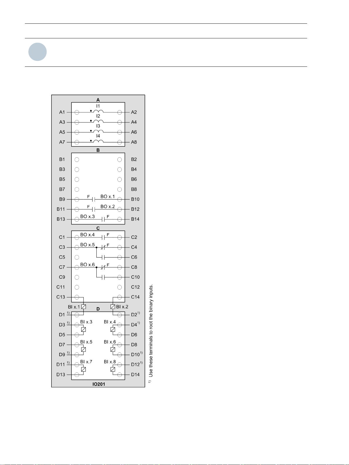
i
i
Electronic Modules
3.2 Input and Output Modules of the Modular Devices
NOTE
x corresponds to the slot in the 19-inch rack.
Terminal and Connection Diagram
For the binary inputs and outputs, the x corresponds to the slot in the 19-inch rack.
[cdio201x-290812-01.tif, 1, en_US]
Figure 3-14
56 SIPROTEC 5, Hardware Description, Manual
IO201 – Terminal Diagram
C53000-G5040-C002-C, Edition 10.2017

Electronic Modules
3.2 Input and Output Modules of the Modular Devices
3.2.3
3.2.3.1
[tdio201x-290812-01.tif, 1, en_US]
Figure 3-15
IO201 – Connection Diagram
Input and Output Module IO202
Description
This input and output module is used as the base measurement module in all protection devices and bay units.
One device can contain several IO202 input and output modules. The number of IO202 input and output
modules depends on the measured values required. Up to 40 measuring channels are possible for each
SIPROTEC device.
The terminals for the following are located on the input and output module IO202:
4 current transformers (optionally protection-class current transformers or instrument transformers)
•
4 voltage transformers
•
8 binary inputs
•
6 binary outputs, of which:
•
– 4 high-speed make contacts (type F)
– 2 high-speed change-over contacts (type F)
The connections are distributed over:
1 x 8-pole current terminal
•
3 x 14-pole voltage terminal
•
SIPROTEC 5, Hardware Description, Manual 57
C53000-G5040-C002-C, Edition 10.2017

i
i
Electronic Modules
3.2 Input and Output Modules of the Modular Devices
3.2.3.2
Overview of Terminals
Terminals
[dwio202p-030211-01.tif, 2, --_--]
Figure 3-16
(1) Current terminal xA
(2) Voltage terminal xB
(3) Voltage terminal xC
(4) Voltage terminal xD
(5) Protective grounding terminal
NOTE
x corresponds to the slot in the 19-inch rack.
IO202 – Terminals
58 SIPROTEC 5, Hardware Description, Manual
C53000-G5040-C002-C, Edition 10.2017

Terminal and Connection Diagram
For the binary inputs and outputs, the x corresponds to the slot in the 19-inch rack.
Electronic Modules
3.2 Input and Output Modules of the Modular Devices
[cdio202x-300812-01.tif, 1, en_US]
Figure 3-17
SIPROTEC 5, Hardware Description, Manual 59
C53000-G5040-C002-C, Edition 10.2017
IO202 – Terminal Diagram
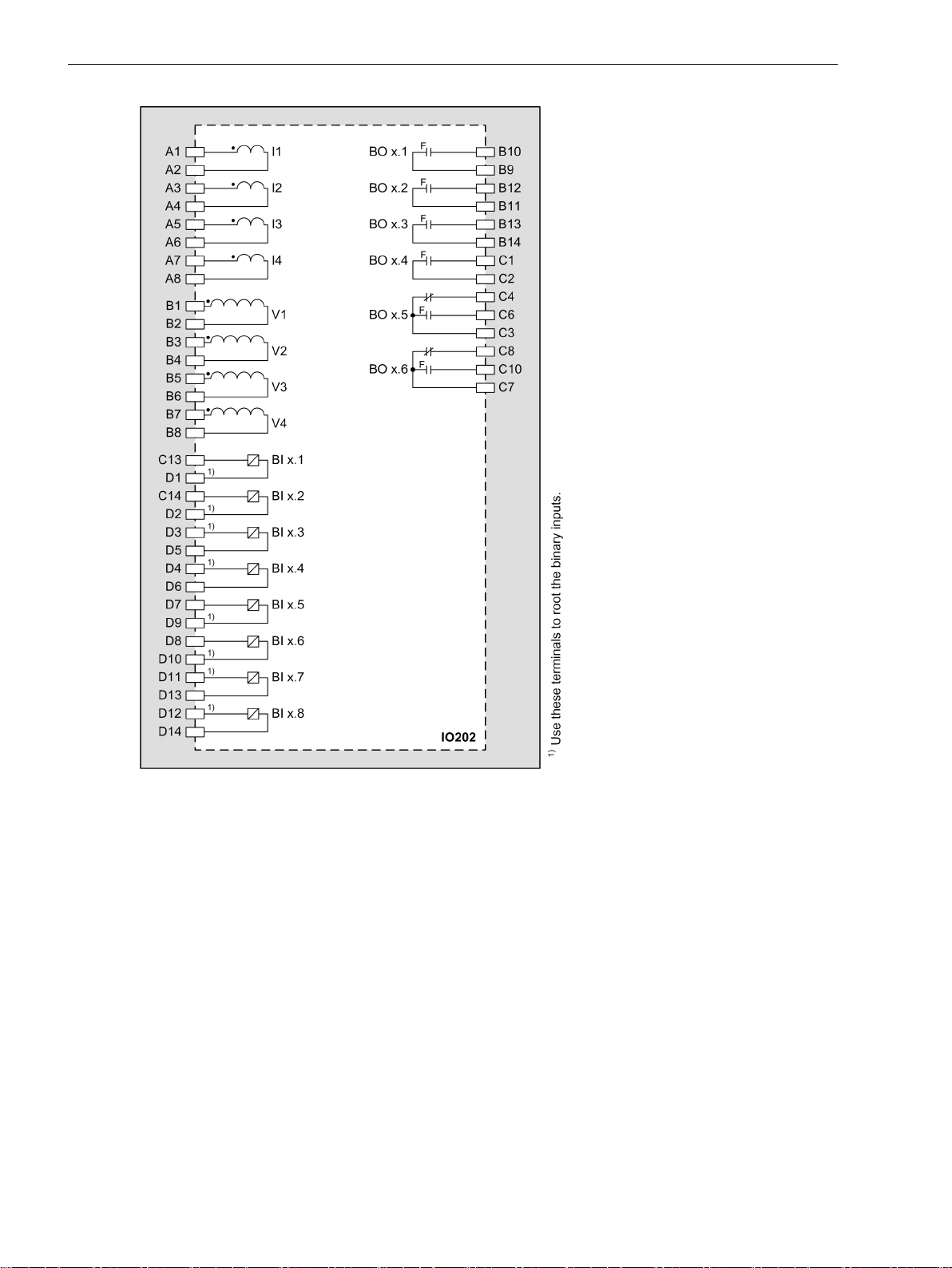
Electronic Modules
3.2 Input and Output Modules of the Modular Devices
[tdio202x-240812-01.tif, 1, en_US]
Figure 3-18
3.2.4
3.2.4.1
60 SIPROTEC 5, Hardware Description, Manual
Input and Output Module IO203
Description
The terminals for the following are located on the input and output module IO203:
8 current transformers (optionally protection-class current transformers or instrument transformers)
•
4 binary inputs (2 binary inputs each with common connection)
•
4 binary outputs with 4 high-speed make contacts (type F)
•
The connections are distributed over:
2 x 8-pole current terminal
•
1 x 14-pole voltage terminal
•
IO202 – Connection Diagram
C53000-G5040-C002-C, Edition 10.2017

i
i
Electronic Modules
3.2 Input and Output Modules of the Modular Devices
3.2.4.2
Overview of Terminals
Terminals
[le_io203, 1, --_--]
Figure 3-19
(1) Current terminal xA
(2) Current terminal xB
(3) Voltage terminal xD
(4) Protective grounding terminal
NOTE
x corresponds to the slot in the 19-inch rack.
SIPROTEC 5, Hardware Description, Manual 61
C53000-G5040-C002-C, Edition 10.2017
IO203 – Terminals

Electronic Modules
3.2 Input and Output Modules of the Modular Devices
Terminal and Connection Diagram
For the binary inputs and outputs, the x corresponds to the slot in the 19-inch rack.
[cdio203x-280812-01.tif, 1, en_US]
Figure 3-20
62 SIPROTEC 5, Hardware Description, Manual
IO203 – Terminal Diagram
C53000-G5040-C002-C, Edition 10.2017

Electronic Modules
3.2 Input and Output Modules of the Modular Devices
3.2.5
3.2.5.1
[tdio203x-110313-01.tif, 1, en_US]
Figure 3-21
IO203 – Connection Diagram
Input and Output Module IO204
Description
The terminals for the following are located on the input and output module IO204:
10 binary inputs
•
4 binary outputs with 4 standard make contacts (type S)
•
4 power relays for controlling 2 motors (forward/backward) with a common auxiliary voltage supply V
•
+, V
-
aux
The power relays operate in interlocked mode, that is, only one relay of each switching pair picks up at a
time thereby avoiding a power-supply short circuit. Note the polarity specified in the terminal and
connection diagram.
The connections are distributed over three 14-pole voltage terminals.
aux
SIPROTEC 5, Hardware Description, Manual 63
C53000-G5040-C002-C, Edition 10.2017

i
i
Electronic Modules
3.2 Input and Output Modules of the Modular Devices
3.2.5.2
Overview of Terminals
Terminals
[dwio204p-201112-01.tif, 2, --_--]
Figure 3-22
(1) Voltage terminal xA
(2) Voltage terminal xC
(3) Voltage terminal xD
(4) Protective grounding terminal
NOTE
x corresponds to the slot in the 19-inch rack.
IO204 – Terminals
64 SIPROTEC 5, Hardware Description, Manual
C53000-G5040-C002-C, Edition 10.2017

Terminal and Connection Diagram
For the binary inputs and outputs, the x corresponds to the slot in the 19-inch rack.
Electronic Modules
3.2 Input and Output Modules of the Modular Devices
[cdio204x-201112-01.tif, 1, en_US]
Figure 3-23
SIPROTEC 5, Hardware Description, Manual 65
C53000-G5040-C002-C, Edition 10.2017
IO204 – Terminal Diagram

Electronic Modules
3.2 Input and Output Modules of the Modular Devices
3.2.6
3.2.6.1
[tdio204x-201112-01.tif, 1, en_US]
Figure 3-24
IO204 – Connection Diagram
Input and Output Module IO205
Description
The terminals for the following are located on the input and output module IO205:
12 binary inputs
•
16 binary outputs with 16 standard make contacts (type S)
•
The connections are distributed over four 14-pole voltage terminals.
66 SIPROTEC 5, Hardware Description, Manual
C53000-G5040-C002-C, Edition 10.2017

i
i
Electronic Modules
3.2 Input and Output Modules of the Modular Devices
3.2.6.2
Overview of Terminals
Terminals
[dwio205p-030211-01.tif, 2, --_--]
Figure 3-25
(1) Voltage terminal xA
(2) Voltage terminal xB
(3) Voltage terminal xC
(4) Voltage terminal xD
(5) Protective grounding terminal
NOTE
x corresponds to the slot in the 19-inch rack.
IO205 – Terminals
SIPROTEC 5, Hardware Description, Manual 67
C53000-G5040-C002-C, Edition 10.2017

Electronic Modules
3.2 Input and Output Modules of the Modular Devices
Terminal and Connection Diagram
For the binary inputs and outputs, the x corresponds to the slot in the 19-inch rack.
[cdio205x-260213-01.tif, 1, en_US]
Figure 3-26
68 SIPROTEC 5, Hardware Description, Manual
IO205 – Terminal Diagram
C53000-G5040-C002-C, Edition 10.2017

Electronic Modules
3.2 Input and Output Modules of the Modular Devices
[tdio205x-240812-01.tif, 1, en_US]
Figure 3-27
3.2.7
3.2.7.1
SIPROTEC 5, Hardware Description, Manual 69
C53000-G5040-C002-C, Edition 10.2017
Input and Output Module IO206
Description
The terminals for the following are located on the input and output module IO206:
6 binary inputs
•
7 binary outputs with 7 standard make contacts (type S)
•
The connections are distributed over two 14-pole voltage terminals.
IO205 – Connection Diagram

i
i
Electronic Modules
3.2 Input and Output Modules of the Modular Devices
3.2.7.2
Overview of Terminals
Terminals
[dwio206p-030211-01.tif, 2, --_--]
Figure 3-28
(1) Voltage terminal xA
(2) Voltage terminal xD
(3) Protective grounding terminal
NOTE
x corresponds to the slot in the 19-inch rack.
IO206 – Terminals
70 SIPROTEC 5, Hardware Description, Manual
C53000-G5040-C002-C, Edition 10.2017

Terminal and Connection Diagram
For the binary inputs and outputs, the x corresponds to the slot in the 19-inch rack.
Electronic Modules
3.2 Input and Output Modules of the Modular Devices
[cdio206x-280812-01.tif, 1, en_US]
Figure 3-29
[tdio206x-050313-02.tif, 1, en_US]
IO206 – Terminal Diagram
Figure 3-30 IO206 – Connection Diagram
SIPROTEC 5, Hardware Description, Manual 71
C53000-G5040-C002-C, Edition 10.2017

i
i
Electronic Modules
3.2 Input and Output Modules of the Modular Devices
3.2.8
3.2.8.1
3.2.8.2
Overview of Terminals
Input and Output Module IO207
Description
The terminals for the following are located on the input and output module IO207:
16 binary inputs
•
8 binary outputs with 8 standard make contacts (type S)
•
The connections are distributed over four 14-pole voltage terminals.
Terminals
[dwio207p-030211-01.tif, 2, --_--]
Figure 3-31
(1) Voltage terminal xA
(2) Voltage terminal xB
(3) Voltage terminal xC
(4) Voltage terminal xD
(5) Protective grounding terminal
NOTE
x corresponds to the slot in the 19-inch rack.
72 SIPROTEC 5, Hardware Description, Manual
IO207 – Terminals
C53000-G5040-C002-C, Edition 10.2017

Terminal and Connection Diagram
For the binary inputs and outputs, the x corresponds to the slot in the 19-inch rack.
Electronic Modules
3.2 Input and Output Modules of the Modular Devices
[cdio207x-260213-01.tif, 1, en_US]
Figure 3-32
SIPROTEC 5, Hardware Description, Manual 73
C53000-G5040-C002-C, Edition 10.2017
IO207 – Terminal Diagram

Electronic Modules
3.2 Input and Output Modules of the Modular Devices
[tdio207x-300812-01.tif, 1, en_US]
Figure 3-33
3.2.9
3.2.9.1
74 SIPROTEC 5, Hardware Description, Manual
Input and Output Module IO208
Description
The terminals for the following are located on the input and output module IO208:
4 current transformers (optionally protection-class current transformers or instrument transformers)
•
4 voltage transformers
•
4 binary inputs
•
11 binary outputs with 3 standard make contacts (type S), 6 high-speed make contacts (type F), and 2
•
high-speed change-over contacts (type F)
The connections are distributed over:
1 x 8-pole current terminal block
•
3 x 14-pole voltage terminal blocks
•
IO207 – Connection Diagram
C53000-G5040-C002-C, Edition 10.2017

Electronic Modules
3.2 Input and Output Modules of the Modular Devices
3.2.9.2
Terminals
Overview of Terminals
[dwio208p-030211-01.tif, 2, --_--]
Figure 3-34
(1)
(2)
(3)
(4)
IO208 – Terminals
Current terminal xA
Voltage terminal xB
Voltage terminal xC
Voltage terminal xD
(5) Protective grounding terminal
1
x corresponds to the slot in the 19-inch rack.
1
1
1
1
SIPROTEC 5, Hardware Description, Manual 75
C53000-G5040-C002-C, Edition 10.2017

Electronic Modules
3.2 Input and Output Modules of the Modular Devices
Terminal and Connection Diagram
For the binary inputs and outputs, the x corresponds to the slot in the 19-inch rack.
[cdio208x-050313-01.tif, 3, en_US]
Figure 3-35
76 SIPROTEC 5, Hardware Description, Manual
IO208 – Terminal Diagram
C53000-G5040-C002-C, Edition 10.2017

Electronic Modules
3.2 Input and Output Modules of the Modular Devices
3.2.10
3.2.10.1
[tdio208x-300812-01.tif, 1, en_US]
Figure 3-36
IO208 – Connection Diagram
Input and Output Module IO209
Description
The terminals for the following are located on the input and output module IO209:
8 binary inputs
•
4 binary outputs with semiconductor-accelerated make contacts (type HS)
•
The connections are distributed over three 14-pole voltage terminals.
SIPROTEC 5, Hardware Description, Manual 77
C53000-G5040-C002-C, Edition 10.2017

i
i
Electronic Modules
3.2 Input and Output Modules of the Modular Devices
3.2.10.2
Overview of Terminals
Terminals
[dwio209p-030211-01.tif, 2, --_--]
Figure 3-37
(1) Voltage terminal xA
(2) Voltage terminal xC
(3) Voltage terminal xD
(4) Protective grounding terminal
NOTE
x corresponds to the slot in the 19-inch rack.
IO209 – Terminals
78 SIPROTEC 5, Hardware Description, Manual
C53000-G5040-C002-C, Edition 10.2017

Terminal and Connection Diagram
For the binary inputs and outputs, the x corresponds to the slot in the 19-inch rack.
Electronic Modules
3.2 Input and Output Modules of the Modular Devices
[cdio209x-110313-01.tif, 1, en_US]
Figure 3-38
SIPROTEC 5, Hardware Description, Manual 79
C53000-G5040-C002-C, Edition 10.2017
IO209 – Terminal Diagram

Electronic Modules
3.2 Input and Output Modules of the Modular Devices
[tdio209x-270812-01.tif, 1, en_US]
Figure 3-39 IO209 – Connection Diagram
3.2.11
3.2.11.1
Input and Output Module IO210
Description
The terminals for the following are located on the input and output module IO210:
4 current transformers (optionally protection-class current transformers or instrument transformers)
•
3 voltage transformers
•
4 high-speed measuring transducer inputs for current (20 mA) or voltage (10 V)
•
7 binary outputs, of which:
•
– 1 standard make contact (type S)
– 4 high-speed make contacts (type F)
– 2 standard change-over contacts (type S)
The connections are distributed over:
1 x 8-pole current terminal
•
3 x 14-pole voltage terminal
•
80 SIPROTEC 5, Hardware Description, Manual
C53000-G5040-C002-C, Edition 10.2017
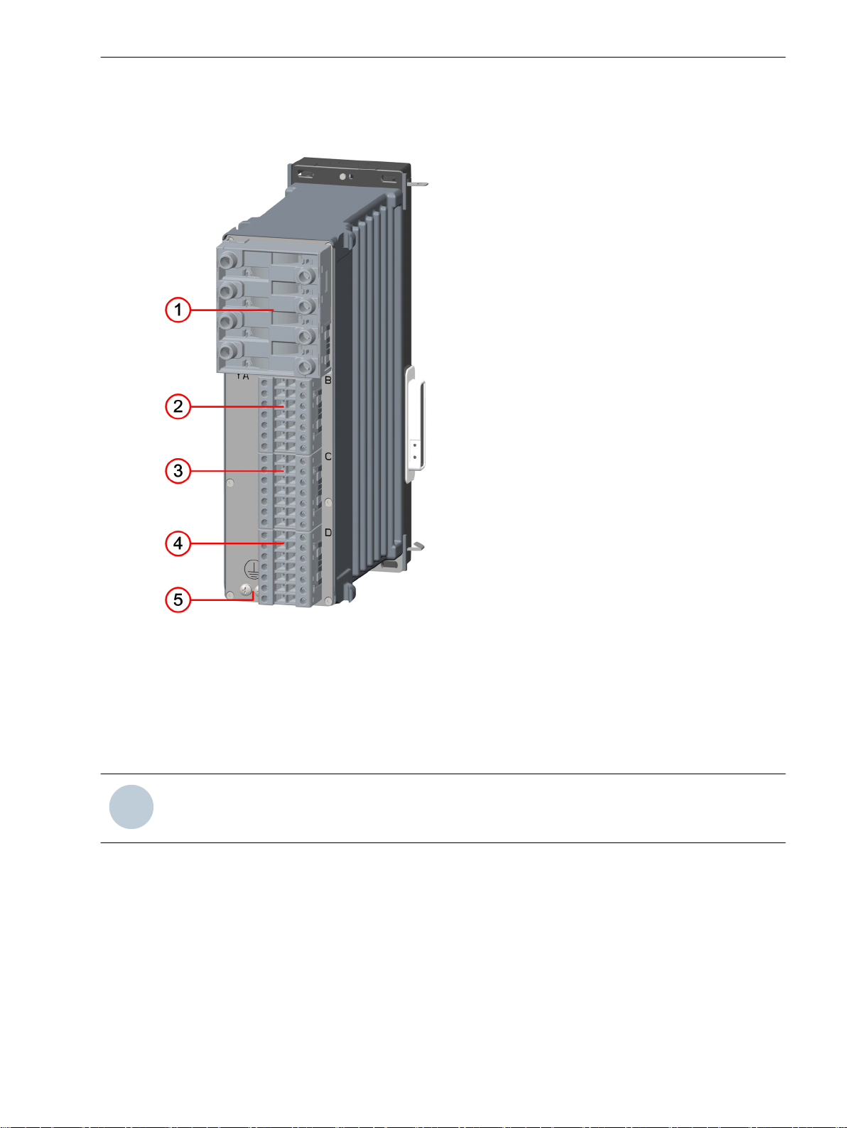
i
i
Electronic Modules
3.2 Input and Output Modules of the Modular Devices
3.2.11.2
Overview of Terminals
Terminals
[dwio202p-030211-01.tif, 2, --_--]
Figure 3-40
(1) Current terminal xA
(2) Voltage terminal xB
(3) Voltage terminal xC
(4) Voltage terminal xD
(5) Protective grounding terminal
NOTE
x corresponds to the slot in the 19-inch rack.
IO210 – Terminals
SIPROTEC 5, Hardware Description, Manual 81
C53000-G5040-C002-C, Edition 10.2017

Electronic Modules
3.2 Input and Output Modules of the Modular Devices
Terminal and Connection Diagram
For the binary inputs and outputs, the x corresponds to the slot in the 19-inch rack.
[cd_io210, 2, en_US]
Figure 3-41
IO210 – Terminal Diagram
(1) Voltage input MT3 with higher voltage immunity (maximum continuous voltage ± 60 V)
82 SIPROTEC 5, Hardware Description, Manual
C53000-G5040-C002-C, Edition 10.2017

Electronic Modules
3.2 Input and Output Modules of the Modular Devices
[td_io210, 2, en_US]
Figure 3-42
3.2.12
3.2.12.1
SIPROTEC 5, Hardware Description, Manual 83
C53000-G5040-C002-C, Edition 10.2017
Input and Output Module IO211
Description
The terminals for the following are located on the input and output module IO211:
8 voltage inputs
•
8 binary inputs
•
The connections are distributed over three 14-pole voltage terminals.
IO210 – Connection Diagram

i
i
Electronic Modules
3.2 Input and Output Modules of the Modular Devices
3.2.12.2
Overview of Terminals
Terminals
[dwio211p-211112-01.tif, 2, --_--]
Figure 3-43
(1) Voltage terminal xA
(2) Voltage terminal xC
(3) Voltage terminal xD
(4) Protective grounding terminal
NOTE
x corresponds to the slot in the 19-inch rack.
IO211 Terminals
84 SIPROTEC 5, Hardware Description, Manual
C53000-G5040-C002-C, Edition 10.2017

Terminal and Connection Diagram
For the binary inputs and outputs, the x corresponds to the slot in the 19-inch rack.
Electronic Modules
3.2 Input and Output Modules of the Modular Devices
[cdio211x-221112-01.tif, 1, en_US]
Figure 3-44
SIPROTEC 5, Hardware Description, Manual 85
C53000-G5040-C002-C, Edition 10.2017
IO211 Terminal Diagram

Electronic Modules
3.2 Input and Output Modules of the Modular Devices
[tdio211x-211112-01.tif, 1, en_US]
Figure 3-45
3.2.13
3.2.13.1
86 SIPROTEC 5, Hardware Description, Manual
Input and Output Module IO212
Description
The terminals for the following are located on the input and output module IO212:
8 high-speed measuring-transducer inputs for current (20 mA) or voltage (10 V)
•
8 binary inputs
•
The connections are distributed over three 14-pole voltage terminals.
IO211 Connection Diagram
C53000-G5040-C002-C, Edition 10.2017

i
i
Electronic Modules
3.2 Input and Output Modules of the Modular Devices
3.2.13.2
Overview of Terminals
Terminals
[dwio204p-201112-01.tif, 2, --_--]
Figure 3-46
(1) Voltage terminal xA
(2) Voltage terminal xC
(3) Voltage terminal xD
(4) Protective grounding terminal
NOTE
x corresponds to the slot in the 19-inch rack.
IO212 – Terminals
SIPROTEC 5, Hardware Description, Manual 87
C53000-G5040-C002-C, Edition 10.2017

Electronic Modules
3.2 Input and Output Modules of the Modular Devices
Terminal and Connection Diagram
For the binary inputs and outputs, the x corresponds to the slot in the 19-inch rack.
[cd_io212, 1, en_US]
Figure 3-47
88 SIPROTEC 5, Hardware Description, Manual
IO212 – Terminal Diagram
C53000-G5040-C002-C, Edition 10.2017

Electronic Modules
3.2 Input and Output Modules of the Modular Devices
3.2.14
3.2.14.1
[tdio212x, 1, en_US]
Figure 3-48
IO212 – Connection Diagram
Input and Output Module IO214
Description
This input and output module is used as the base measurement module in all protection devices. One device
can contain several IO214 input and output modules. The number of IO214 input and output modules
depends on the measured values required. Up to 40 measuring channels are possible for each SIPROTEC
device.
The terminals for the following are located on the input and output module IO214:
4 current transformers (optionally protection-class current transformers or instrument transformers)
•
4 voltage transformers
•
2 binary inputs
•
5 binary outputs with 4 high-speed make contacts (type F) and 1 high-speed change-over contact (type
•
F)
The connections are distributed over:
1 x 8-pole current terminal
•
3 x 14-pole voltage terminal
•
SIPROTEC 5, Hardware Description, Manual 89
C53000-G5040-C002-C, Edition 10.2017

i
i
Electronic Modules
3.2 Input and Output Modules of the Modular Devices
3.2.14.2
Overview of Terminals
Terminals
[dwio214p-030211-01.tif, 2, --_--]
Figure 3-49
(1) Current terminal xA
(2) Voltage terminal xB
(3) Voltage terminal xC
(4) Voltage terminal xD
(5) Protective grounding terminal
NOTE
x corresponds to the slot in the 19-inch rack.
IO214 – Terminals
90 SIPROTEC 5, Hardware Description, Manual
C53000-G5040-C002-C, Edition 10.2017

Terminal and Connection Diagram
For the binary inputs and outputs, the x corresponds to the slot in the 19-inch rack.
Electronic Modules
3.2 Input and Output Modules of the Modular Devices
[cdio214x-260213-01.tif, 1, en_US]
Figure 3-50
SIPROTEC 5, Hardware Description, Manual 91
C53000-G5040-C002-C, Edition 10.2017
IO214 – Terminal Diagram

Electronic Modules
3.2 Input and Output Modules of the Modular Devices
3.2.15
3.2.15.1
[tdio214x-270812-01.tif, 1, en_US]
Figure 3-51
IO214 – Connection Diagram
Input and Output Module IO215
Description
This input and output module is used as the base measurement module in all protection devices and bay units.
One device can contain several IO215 input and output modules. The number of IO215 input and output
modules depends on the measured values required. Up to 40 measuring channels are possible for each
SIPROTEC device.
The terminals for the following are located on the input and output module IO215:
4 current transformers (optionally protection-class current transformers or instrument transformers)
•
4 voltage transformers for the connection of an isolation amplifier P27000-H1-S011
•
Connect each phase of the device via this isolation amplifier with capacitive voltage transformers from
the Trench Co. The voltage input is specially designed for a measuring range up to of 7.07 V.
8 binary inputs
•
6 binary outputs, of which:
•
– 4 high-speed make contacts (type F)
– 2 high-speed change-over contacts (type F)
The connections are distributed over:
1 x 8-pole current terminal
•
3 x 14-pole voltage terminal
•
3.2.15.2
92 SIPROTEC 5, Hardware Description, Manual
Terminals
The terminal and connection diagram is identical to the input and output module IO202 in the expansion
module.
You can find more information in chapter 3.2.3.2 Terminals, Figure 3-17 and Figure 3-18.
C53000-G5040-C002-C, Edition 10.2017

i
i
Electronic Modules
3.2 Input and Output Modules of the Modular Devices
3.2.16
3.2.16.1
3.2.16.2
Overview of Terminals
Input Module IO230
Description
The terminals for the following are located on the IO230 module:
48 binary inputs
•
The connections are distributed over six 10-pole connection terminals.
NOTE
Note that the IO230 input module has group switching for switching thresholds. The thresholds of the
binary inputs can be switched only in groups of 4. 4th group x1 to x4 and 4th group x7 to x10 (x = A, C, D,
E, G, H).
Terminals
[dwio230x-030713-01.tif, 2, --_--]
Figure 3-52
(1) Terminal xA
(2) Terminal xC
(3) Terminal xD
(4) Protective grounding terminal
(5) Terminal xH
(6) Terminal xG
(7) Terminal xE
SIPROTEC 5, Hardware Description, Manual 93
C53000-G5040-C002-C, Edition 10.2017
IO230 – Terminals

i
i
i
i
Electronic Modules
3.2 Input and Output Modules of the Modular Devices
NOTE
x corresponds to the slot in the 19-inch rack.
Terminal and Connection Diagram
NOTE
The polarities of the voltages at the binary inputs must not be reversed!
[cdio230x-030713-01.tif, 1, en_US]
Figure 3-53
94 SIPROTEC 5, Hardware Description, Manual
IO230 – Terminal Diagram
C53000-G5040-C002-C, Edition 10.2017

Electronic Modules
3.2 Input and Output Modules of the Modular Devices
[tdio230x, 1, en_US]
Figure 3-54
IO230 – Connection Diagram
SIPROTEC 5, Hardware Description, Manual 95
C53000-G5040-C002-C, Edition 10.2017

i
i
Electronic Modules
3.2 Input and Output Modules of the Modular Devices
3.2.17
3.2.17.1
3.2.17.2
Overview of Terminals
Input and Output Module IO231
Description
The terminals for the following are located on the input and output module IO231:
24 binary inputs
•
24 binary outputs, standard make contacts (type S)
•
The connections are distributed over six 10-pole connection terminals.
Terminals
[dwio230x-030713-01.tif, 2, --_--]
Figure 3-55
(1) Terminal xA
(2) Terminal xC
(3) Terminal xD
(4) Protective grounding terminal
(5) Terminal xH
(6) Terminal xG
(7) Terminal xE
NOTE
x corresponds to the slot in the 19-inch rack.
96 SIPROTEC 5, Hardware Description, Manual
IO231 – Terminals
C53000-G5040-C002-C, Edition 10.2017

Terminal and Connection Diagram
i
i
NOTE
The polarities of the voltages at the binary inputs must not be reversed!
Electronic Modules
3.2 Input and Output Modules of the Modular Devices
[cd_io231x, 2, en_US]
Figure 3-56
SIPROTEC 5, Hardware Description, Manual 97
C53000-G5040-C002-C, Edition 10.2017
IO231 – Terminal Diagram

Electronic Modules
3.2 Input and Output Modules of the Modular Devices
[td_tdio231x, 1, en_US]
Figure 3-57
3.2.18
3.2.18.1
98 SIPROTEC 5, Hardware Description, Manual
Input Module IO233
Description
The terminals for the following are located on the input module IO233:
48 binary inputs
•
IO231 – Connection Diagram
C53000-G5040-C002-C, Edition 10.2017

The connections are distributed over six 10-pole terminals.
i
i
i
i
Electronic Modules
3.2 Input and Output Modules of the Modular Devices
3.2.18.2
Overview of Terminals
Terminals
[dw_io233x, 1, en_US]
Figure 3-58
(1) Terminal xA
(2) Terminal xC
(3) Terminal xD
(4) Protective grounding terminal
(5) Terminal xH
(6) Terminal xG
(7) Terminal xE
NOTE
x corresponds to the slot in the 19-inch rack.
Terminal and Connection Diagram
NOTE
The polarities of the voltages at the binary inputs must not be reversed!
IO233 – Terminals
SIPROTEC 5, Hardware Description, Manual 99
C53000-G5040-C002-C, Edition 10.2017

Electronic Modules
3.2 Input and Output Modules of the Modular Devices
[cd_io233x, 1, en_US]
Figure 3-59
IO233 – Terminal Diagram
100 SIPROTEC 5, Hardware Description, Manual
C53000-G5040-C002-C, Edition 10.2017
 Loading...