

Page 1

Preface
Table of Contents
SIPROTEC 4
Voltage and Frequency
Protection 7RW80
V4.6
Manual
Introduction
Functions
Mounting and Commissioning
Technical Data
Ordering Information and Accessories
Terminal Assignments
Connection Examples
Default Settings and Protocol-dependent
Functions
Functions, Settings, Information
1
2
3
4
A
B
C
D
E
C53000-G1140-C233-4
Literature
Glossary
Index
Page 2

i
i
NOTE
For your own safety, observe the warnings and safety instructions contained in this document, if available.
Disclaimer of Liability
We have checked the contents of this manual against the
hardware and software described. However, deviations
from the description cannot be completely ruled out, so
that no liability can be accepted for any errors or omissions
contained in the information given.
The information given in this document is reviewed regularly and any necessary corrections will be included in
subsequent editions. We appreciate any suggested
improvements.
We reserve the right to make technical improvements
without notice.
Document version V04.03.00
Release date 07.2018
Copyright
Copyright © Siemens AG 2018. All rights reserved.
Dissemination or reproduction of this document, or evalua-
tion and communication of its contents, is not authorized
except where expressly permitted. Violations are liable for
damages. All rights reserved, particularly for the purposes
of patent application or trademark registration.
Registered Trademarks
SIPROTEC, SINAUT, SICAM and DIGSI are registered trademarks of Siemens AG. Other designations in this manual
might be trademarks whose use by third parties for their
own purposes would infringe the rights of the owner.
Page 3

Preface
Purpose of the Manual
This manual describes the functions, operation, installation, and commissioning of devices 7RW80. In particular, one will find:
Information regarding the configuration of the scope of the device and a description of the device func-
•
tions and settings → Chapter 2;
Instructions for Installation and Commissioning → Chapter 3;
•
Compilation of the Technical Data → Chapter 4;
•
As well as a compilation of the most significant data for advanced users → Appendix.
•
General information with regard to design, configuration, and operation of SIPROTEC 4 devices are set out in
the SIPROTEC 4 System Description /1/ SIPROTEC 4 System Description.
Target Audience
Protection-system engineers, commissioning engineers, persons entrusted with the setting, testing and maintenance of selective protection, automation and control equipment, and operating personnel in electrical
installations and power plants.
Scope
This manual applies to: SIPROTEC 4 Voltage and Frequency Protection 7RW80; Firmware-Version V4.6.
Indication of Conformity
Additional Standards IEEE Std C37.90 (see Chapter 4 "Technical Data")
This product is UL-certified according to the Technical Data. file E194016
[ul-schutz-7sx80-100310, 1, --_--]
This product complies with the directive of the Council of the European Communities on the
approximation of the laws of the Member States relating to electromagnetic compatibility
(EMC Council Directive 2004/108/EC) and concerning electrical equipment for use within
specified voltage limits (Low-voltage Directive 2006/95 EC).
This conformity is proved by tests conducted by Siemens AG in accordance with the Council
Directive in agreement with the generic standards EN 61000-6-2 and EN 61000-6-4 for EMC
directive, and with the standard EN 60255-27 for the low-voltage directive.
The device has been designed and produced for industrial use.
The product conforms with the international standards of the series IEC 60255 and the
German standard VDE 0435.
SIPROTEC 4, 7RW80, Manual
C53000-G1140-C233-4, Edition 07.2018
3
Page 4
!
!
!
Preface
Additional Support
For questions about the system, please contact your Siemens sales partner.
Support
Our Customer Support Center provides a 24-hour service.
Phone: +49 (180) 524-7000
Fax: +49 (180) 524-2471
E-Mail: support.energy@siemens.com
Training Courses
Inquiries regarding individual training courses should be addressed to our Training Center:
Siemens AG
Siemens Power Academy TD
Humboldtstraße 59
90459 Nürnberg
Germany
Phone: +49 (911) 433-7415
Fax: +49 (911) 433-7929
E-Mail: poweracademy@siemens.com
Internet: www.siemens.com/poweracademy
Notes on Safety
This document is not a complete index of all safety measures required for operation of the equipment (module
or device). However, it comprises important information that must be followed for personal safety, as well as
to avoid material damage. Information is highlighted and illustrated as follows according to the degree of
danger:
DANGER
DANGER means that death or severe injury will result if the measures specified are not taken.
²
WARNING
WARNING means that death or severe injury may result if the measures specified are not taken.
²
CAUTION
Comply with all instructions, in order to avoid death or severe injuries.
Comply with all instructions, in order to avoid death or severe injuries.
CAUTION means that medium-severe or slight injuries can occur if the specified measures are not taken.
Comply with all instructions, in order to avoid moderate or minor injuries.
²
4 SIPROTEC 4, 7RW80, Manual
C53000-G1140-C233-4, Edition 07.2018
Page 5

NOTICE
i
i
NOTICE means that property damage can result if the measures specified are not taken.
Comply with all instructions, in order to avoid property damage.
²
NOTE
Important information about the product, product handling or a certain section of the documentation
which must be given particular attention.
Qualified Electrical Engineering Personnel
Only qualified electrical engineering personnel may commission and operate the equipment (module, device)
described in this document. Qualified electrical engineering personnel in the sense of this manual are people
who can demonstrate technical qualifications as electrical technicians. These persons may commission,
isolate, ground and label devices, systems and circuits according to the standards of safety engineering.
Proper Use
The equipment (device, module) may be used only for such applications as set out in the catalogs and the
technical description, and only in combination with third-party equipment recommended and approved by
Siemens.
Problem-free and safe operation of the product depends on the following:
Proper transport
•
Proper storage, setup and installation
•
Proper operation and maintenance
•
When electrical equipment is operated, hazardous voltages are inevitably present in certain parts. If proper
action is not taken, death, severe injury or property damage can result:
The equipment must be grounded at the grounding terminal before any connections are made.
•
All circuit components connected to the power supply may be subject to dangerous voltage.
•
Hazardous voltages may be present in equipment even after the supply voltage has been disconnected
•
(capacitors can still be charged).
Preface
Operation of equipment with exposed current-transformer circuits is prohibited. Before disconnecting the
•
equipment, ensure that the current-transformer circuits are short-circuited.
The limiting values stated in the document must not be exceeded. This must also be considered during
•
testing and commissioning.
Typographic and Symbol Conventions
The following text formats are used when literal information from the device or to the device appear in the
text flow:
Parameter Names
Designators of configuration or function parameters which may appear word-for-word in the display of the
device or on the screen of a personal computer (with operation software DIGSI), are marked in bold letters in
monospace type style. The same applies to titles of menus.
1234A
Parameter addresses have the same character style as parameter names. Parameter addresses contain the
suffix A in the overview tables if the parameter can only be set in DIGSI via the option Display additional
settings.
Parameter Options
Possible settings of text parameters, which may appear word-for-word in the display of the device or on the
screen of a personal computer (with operation software DIGSI), are additionally written in italics. The same
applies to the options of the menus.
SIPROTEC 4, 7RW80, Manual 5
C53000-G1140-C233-4, Edition 07.2018
Page 6
Preface
Indications
Designators for information, which may be output by the relay or required from other devices or from the
switch gear, are marked in a monospace type style in quotation marks.
Deviations may be permitted in drawings and tables when the type of designator can be obviously derived
from the illustration.
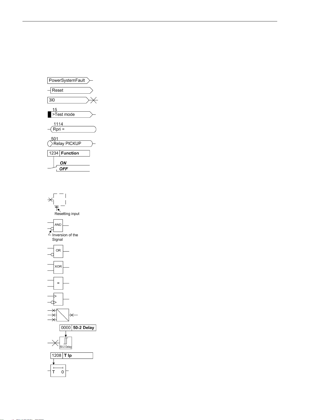
The following symbols are used in drawings:
Device-internal logical input signal
Device-internal logical output signal
Internal input signal of an analog quantity
External binary input signal with number (binary input,
input indication)
External binary output signal with number
(example of a value indication)
External binary output signal with number (device indication) used as
input signal
Example of a parameter switch designated FUNCTION with address
1234 and the possible settings ON and OFF
Besides these, graphical symbols are used in accordance with IEC 60617-12 and IEC 60617-13 or similar.
Some of the most frequently used are listed below:
Analog input variable
AND-gate operation of input values
OR-gate operation of input values
Exclusive OR gate (antivalence): output is active, if only one of the
inputs is active
Coincidence gate: output is active, if both inputs are active or inactive
at the same time
Dynamic inputs (edge-triggered) above with positive, below with
negative edge
Formation of one analog output signal from a number of analog input
signals
Limit stage with setting address and parameter designator (name)
Timer (pickup delay T, example adjustable) with setting address and
parameter designator (name)
6 SIPROTEC 4, 7RW80, Manual
C53000-G1140-C233-4, Edition 07.2018
Page 7

Timer (dropout delay T, example non-adjustable)
Dynamic triggered pulse timer T (monoflop)
Static memory (SR flipflop) with setting input (S), resetting input (R),
output (Q) and inverted output (Q), setting input dominant
Static memory (RS-flipflop) with setting input (S), resetting input (R),
output (Q) and inverted output (Q), resetting input dominant
Preface
SIPROTEC 4, 7RW80, Manual 7
C53000-G1140-C233-4, Edition 07.2018
Page 8

8 SIPROTEC 4, 7RW80, Manual
C53000-G1140-C233-4, Edition 07.2018
Page 9

Table of Contents
Preface..........................................................................................................................................................3
1 Introduction................................................................................................................................................15
1.1 Overall Operation..............................................................................................................16
1.2 Application Scope............................................................................................................. 18
1.3 Characteristics.................................................................................................................. 20
2 Functions.................................................................................................................................................... 23
2.1 General.............................................................................................................................24
2.1.1 Functional Scope......................................................................................................... 24
2.1.1.1 Functional Description........................................................................................... 24
2.1.1.2 Setting Notes......................................................................................................... 24
2.1.1.3 Settings................................................................................................................. 25
2.1.2 Device, General Settings.............................................................................................. 26
2.1.2.1 Functional Description........................................................................................... 26
2.1.2.2 Setting Notes......................................................................................................... 27
2.1.2.3 Settings................................................................................................................. 27
2.1.2.4 Information List..................................................................................................... 27
2.1.3 Power System Data 1...................................................................................................28
2.1.3.1 Functional Description........................................................................................... 28
2.1.3.2 Setting Notes......................................................................................................... 29
2.1.3.3 Settings................................................................................................................. 31
2.1.3.4 Information List..................................................................................................... 32
2.1.4 Oscillographic Fault Records........................................................................................ 32
2.1.4.1 Functional Description........................................................................................... 32
2.1.4.2 Setting Notes......................................................................................................... 33
2.1.4.3 Settings................................................................................................................. 34
2.1.4.4 Information List..................................................................................................... 34
2.1.5 Settings Groups........................................................................................................... 34
2.1.5.1 Functional Description........................................................................................... 34
2.1.5.2 Setting Notes......................................................................................................... 34
2.1.5.3 Settings................................................................................................................. 35
2.1.5.4 Information List..................................................................................................... 35
2.1.6 Power System Data 2...................................................................................................35
2.1.6.1 Functional Description........................................................................................... 35
2.1.6.2 Setting Notes......................................................................................................... 35
2.1.6.3 Settings................................................................................................................. 35
2.1.6.4 Information List..................................................................................................... 35
2.1.7 EN100-Module............................................................................................................ 36
2.1.7.1 Functional Description........................................................................................... 36
2.1.7.2 Setting Notes......................................................................................................... 36
2.1.7.3 Information List..................................................................................................... 36
2.2 Voltage Protection 27, 59..................................................................................................37
2.2.1 Measurement Principle................................................................................................ 37
SIPROTEC 4, 7RW80, Manual 9
C53000-G1140-C233-4, Edition 07.2018
Page 10

Table of Contents
2.2.2 Overvoltage Protection 59........................................................................................... 38
2.2.3 Undervoltage Protection 27......................................................................................... 39
2.2.4 Setting Notes...............................................................................................................41
2.2.5 Settings.......................................................................................................................44
2.2.6 Information List...........................................................................................................45
2.3 Frequency Protection 81 O/U.............................................................................................46
2.3.1 Functional Description.................................................................................................46
2.3.2 Setting Notes...............................................................................................................47
2.3.3 Settings.......................................................................................................................48
2.3.4 Information List...........................................................................................................49
2.4 Load Restoration............................................................................................................... 50
2.4.1 Functional Description.................................................................................................50
2.4.2 Setting Notes...............................................................................................................54
2.4.3 Settings.......................................................................................................................57
2.4.4 Information List...........................................................................................................60
2.5 Supervision Functions....................................................................................................... 61
2.5.1 Measurement Supervision........................................................................................... 61
2.5.1.1 General..................................................................................................................61
2.5.1.2 Hardware Monitoring ............................................................................................ 61
2.5.1.3 Software Monitoring ............................................................................................. 61
2.5.1.4 Monitoring of the Transformer Circuits................................................................... 62
2.5.1.5 Broken Wire Monitoring of Voltage Transformer Circuits......................................... 63
2.5.1.6 Setting Notes......................................................................................................... 64
2.5.1.7 Settings................................................................................................................. 64
2.5.1.8 Information List..................................................................................................... 65
2.5.2 Trip Circuit Supervision 74TC....................................................................................... 65
2.5.2.1 Functional Description........................................................................................... 65
2.5.2.2 Setting Notes......................................................................................................... 68
2.5.2.3 Settings................................................................................................................. 68
2.5.2.4 Information List..................................................................................................... 69
2.5.3 Malfunction Responses of the Monitoring Functions.................................................... 69
2.5.3.1 Functional Description........................................................................................... 69
2.6 Flexible Protection Functions.............................................................................................71
2.6.1 Functional Description.................................................................................................71
2.6.2 Setting Notes...............................................................................................................74
2.6.3 Settings.......................................................................................................................77
2.6.4 Information List...........................................................................................................78
2.7 Synchrocheck................................................................................................................... 80
2.7.1 Allgemeines................................................................................................................ 80
2.7.2 Functional Sequence................................................................................................... 81
2.7.3 De-energized Switching...............................................................................................82
2.7.4 Direct Command / Blocking..........................................................................................83
2.7.5 Interaction with Control and External Control...............................................................84
2.7.6 Setting Notes...............................................................................................................84
2.7.7 Settings.......................................................................................................................88
2.7.8 Information List...........................................................................................................89
2.8 24 Overexcit. Protection (Volt/Hertz)................................................................................. 91
2.8.1 Functional Description.................................................................................................91
2.8.2 Setting Notes...............................................................................................................93
10 SIPROTEC 4, 7RW80, Manual
C53000-G1140-C233-4, Edition 07.2018
Page 11

Table of Contents
2.8.3 Settings.......................................................................................................................95
2.8.4 Information List...........................................................................................................95
2.9 Jump of Voltage Vector..................................................................................................... 96
2.9.1 Functional Description.................................................................................................96
2.9.2 Setting Notes...............................................................................................................98
2.9.3 Settings.......................................................................................................................99
2.9.4 Information List...........................................................................................................99
2.10 Phase Rotation................................................................................................................ 100
2.10.1 Functional Description...............................................................................................100
2.10.2 Setting Notes.............................................................................................................100
2.11 Function Logic................................................................................................................ 101
2.11.1 Pickup Logic of the Entire Device................................................................................101
2.11.2 Tripping Logic of the Entire Device.............................................................................101
2.11.3 Setting Notes.............................................................................................................102
2.12 Auxiliary Functions..........................................................................................................103
2.12.1 Message Processing...................................................................................................103
2.12.1.1 LED Displays and Binary Outputs (Output Relays)..................................................103
2.12.1.2 Information on the Integrated Display (LCD) or Personal Computer....................... 103
2.12.1.3 Information to a Control Center............................................................................105
2.12.2 Statistics....................................................................................................................105
2.12.2.1 Functional Description......................................................................................... 105
2.12.2.2 Setting Notes....................................................................................................... 105
2.12.2.3 Information List................................................................................................... 105
2.12.3 Measurement............................................................................................................105
2.12.3.1 Display of Measured Values.................................................................................. 106
2.12.3.2 Transfer of Measured Values................................................................................ 107
2.12.3.3 Information List................................................................................................... 107
2.12.4 Min/Max Measurement Setup.................................................................................... 108
2.12.4.1 Functional Description......................................................................................... 108
2.12.4.2 Setting Notes....................................................................................................... 108
2.12.4.3 Settings............................................................................................................... 108
2.12.4.4 Information List................................................................................................... 108
2.12.5 Set Points for Measured Values.................................................................................. 109
2.12.5.1 Setting Notes....................................................................................................... 109
2.12.6 Set Points for Statistic................................................................................................ 109
2.12.6.1 Functional Description......................................................................................... 109
2.12.6.2 Setting Notes....................................................................................................... 109
2.12.6.3 Information List................................................................................................... 110
2.12.7 Energy Metering........................................................................................................110
2.12.7.1 Setting Notes....................................................................................................... 110
2.12.7.2 Settings............................................................................................................... 110
2.12.7.3 Information List................................................................................................... 110
2.12.8 Commissioning Aids.................................................................................................. 110
2.12.8.1 Functional Description......................................................................................... 110
2.13 Breaker Control...............................................................................................................112
2.13.1 Control Device...........................................................................................................112
2.13.1.1 Functional Description......................................................................................... 112
2.13.1.2 Informationsübersicht..........................................................................................113
2.13.2 Types of Commands.................................................................................................. 113
2.13.2.1 Functional Description......................................................................................... 113
SIPROTEC 4, 7RW80, Manual 11
C53000-G1140-C233-4, Edition 07.2018
Page 12

Table of Contents
2.13.3 Command Sequence..................................................................................................113
2.13.3.1 Functional Description......................................................................................... 114
2.13.4 Switchgear Interlocking............................................................................................. 114
2.13.4.1 Functional Description......................................................................................... 114
2.13.5 Command Logging.................................................................................................... 118
2.13.5.1 Functional Description......................................................................................... 119
2.14 Notes on Device Operation..............................................................................................120
2.14.1 Different operation....................................................................................................120
3 Mounting and Commissioning................................................................................................................. 123
3.1 Mounting and Connections............................................................................................. 124
3.1.1 Configuration Information......................................................................................... 124
3.1.2 Hardware Modifications.............................................................................................127
3.1.2.1 Disassembly.........................................................................................................127
3.1.2.2 Connections of the Voltage Terminals...................................................................131
3.1.2.3 Interface Modules................................................................................................ 132
3.1.2.4 Reassembly..........................................................................................................134
3.1.3 Installation................................................................................................................ 135
3.1.3.1 General................................................................................................................135
3.1.3.2 Panel Flush Mounting...........................................................................................136
3.1.3.3 Cubicle Mounting.................................................................................................137
3.1.3.4 Panel Surface Mounting....................................................................................... 138
3.2 Checking Connections.....................................................................................................140
3.2.1 Checking the Data Connections of the Interfaces........................................................140
3.2.2 Checking the System Connections............................................................................. 142
3.3 Commissioning............................................................................................................... 144
3.3.1 Test Mode and Transmission Block.............................................................................145
3.3.2 Testing the System Interface .....................................................................................145
3.3.3 Configuring Communication Modules........................................................................146
3.3.4 Checking the Status of Binary Inputs and Outputs...................................................... 150
3.3.5 Testing User-Defined Functions..................................................................................152
3.3.6 Voltage and Phase Rotation Testing........................................................................... 152
3.3.7 Polarity Check for Voltage Input V3.............................................................................153
3.3.8 Trip/Close Tests for the Configured Operating Devices................................................ 155
3.3.9 Creating Oscillographic Recordings for Tests.............................................................. 156
3.4 Final Preparation of the Device........................................................................................157
4 Technical Data.......................................................................................................................................... 159
4.1 General Device Data........................................................................................................160
4.1.1 Analog Inputs............................................................................................................160
4.1.2 Auxiliary voltage........................................................................................................160
4.1.3 Binary Inputs and Outputs......................................................................................... 160
4.1.4 Communication Interfaces.........................................................................................161
4.1.5 Electrical Tests...........................................................................................................164
4.1.6 Mechanical Tests....................................................................................................... 165
4.1.7 Climatic Stress Tests.................................................................................................. 166
4.1.8 Service Conditions..................................................................................................... 167
4.1.9 Constructive Design...................................................................................................167
4.1.10 UL certification conditions......................................................................................... 167
12 SIPROTEC 4, 7RW80, Manual
C53000-G1140-C233-4, Edition 07.2018
Page 13

Table of Contents
4.2 Voltage Protection.......................................................................................................... 169
4.3 Frequency Protection 81 O/U...........................................................................................171
4.4 Load Restoration............................................................................................................. 172
4.5 Flexible Protection Functions ..........................................................................................173
4.6 Synchrocheck 25 ............................................................................................................175
4.7 Overecxitation Protection 24...........................................................................................177
4.8 Jump of Voltage Vector................................................................................................... 179
4.9 User-defined Functions (CFC).......................................................................................... 180
4.10 Auxiliary Functions..........................................................................................................185
4.11 Switching Device Control................................................................................................ 188
4.12 Dimensions.....................................................................................................................189
4.12.1 Panel Flush and Cubicle Mounting (Housing Size 1/6) ................................................189
4.12.2 Panel Surface Mounting (Housing Size 1/6) ............................................................... 190
4.12.3 Bottom view..............................................................................................................190
A Ordering Information and Accessories.....................................................................................................191
A.1 Ordering Information 7RW80 V4.6 ................................................................................. 192
A.2 Accessories.....................................................................................................................195
B Terminal Assignments..............................................................................................................................197
B.1 7RW80 — Housing for Panel Flush Mounting or Cubicle Mounting...................................198
B.2 7RW80 — Housing for panel surface mounting................................................................199
C Connection Examples............................................................................................................................... 201
C.1 Connection Examples for Voltage Transformers...............................................................202
D Default Settings and Protocol-dependent Functions............................................................................... 207
D.1 LEDs............................................................................................................................... 208
D.2 Binary Input.................................................................................................................... 209
D.3 Binary Output................................................................................................................. 210
D.4 Function Keys................................................................................................................. 211
D.5 Default Display................................................................................................................212
D.6 Protocol-dependent Functions.........................................................................................213
E Functions, Settings, Information..............................................................................................................215
E.1 Functional Scope............................................................................................................ 216
E.2 Settings.......................................................................................................................... 217
E.3 Information List.............................................................................................................. 226
E.4 Group Indications............................................................................................................246
E.5 Measured Values.............................................................................................................247
Literature.................................................................................................................................................. 249
Glossary.................................................................................................................................................... 251
Index.........................................................................................................................................................261
SIPROTEC 4, 7RW80, Manual 13
C53000-G1140-C233-4, Edition 07.2018
Page 14

14 SIPROTEC 4, 7RW80, Manual
C53000-G1140-C233-4, Edition 07.2018
Page 15

1
Introduction
The device family SIPROTEC 7RW80 devices is introduced in this section. An overview of the devices is
presented in their application, characteristics, and scope of functions.
1.1 Overall Operation 16
1.2 Application Scope 18
1.3 Characteristics 20
SIPROTEC 4, 7RW80, Manual 15
C53000-G1140-C233-4, Edition 07.2018
Page 16
Introduction
1.1 Overall Operation
1.1
Analog Inputs
Overall Operation
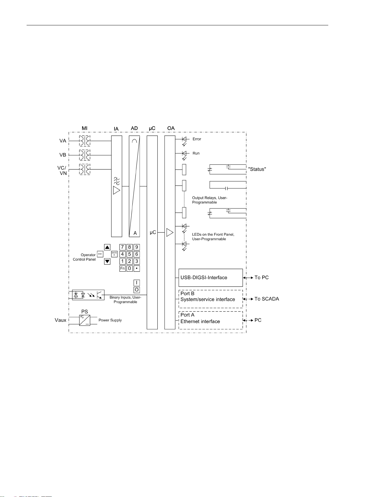
The Voltage and Frequency protection SIPROTEC 7RW80 is equipped with a high performance microprocessor.
This provides numerical processing of all functions in the device, from the acquisition of the measured values
up to the output of commands to the circuit breakers. Figure 1-1 shows the basic structure of the device
7RW80.
The measuring inputs MI transform the voltages derived from the instrument transformers and match them to
the internal signal levels for processing in the device. Three voltage inputs are available in the MI section.
[hw-struktur-7rw80-100519, 1, en_US]
Figure 1-1
Voltage inputs can either be used to measure the three phase-to-ground voltages, or two phase-to-phase
voltages and the displacement voltage (e–n voltage) or for any other voltage. It is also possible to connect two
phase-to-phase voltages in open-delta connection.
The analog input quantities are passed on to the input amplifiers (IA). The input amplifier IA element provides
a high-resistance termination for the input quantities. It consists of filters that are optimized for measuredvalue processing with regard to bandwidth and processing speed.
The analog-to-digital (AD) transformer group consists of a an analog-to-digital converter and memory components for the transmission of data to the microcomputer.
Microcomputer System
Apart from processing the measured values, the microcomputer system (μC) also executes the actual protection and control functions. They especially include:
16 SIPROTEC 4, 7RW80, Manual
Hardware structure of the numerical Voltage and Frequency Protection Device 7RW80
C53000-G1140-C233-4, Edition 07.2018
Page 17

Filtering and preparation of the measured quantities
•
Continuous monitoring of the measured quantities
•
Monitoring of the pickup conditions for the individual protective functions
•
Interrogation of limit values and sequences in time
•
Control of signals for the logic functions
•
Output of control commands for switching devices
•
Recording of messages, fault data and fault values for analysis
•
Management of the operating system and the associated functions such as data recording, real-time
•
clock, communication, interfaces, etc.
The information is distributed via output amplifiers (OA).
•
Binary Inputs and Outputs
The computer system obtains external information through the binary input/output boards (inputs and
outputs). The computer system obtains information from the system (e.g remote resetting) or from external
equipment (e.g. blocking commands). These outputs include, in particular, trip commands to circuit breakers
and signals for the remote indication of important events and conditions.
Front Panel
Introduction
1.1 Overall Operation
Information such as messages related to events, states, measured values and the functional status of the
device are visualized by light-emitting diodes (LEDs) and a display screen (LCD) on the front panel.
Integrated control and numeric keys in conjunction with the LCD enable interaction with the remote device.
These elements can be used to access the device for information such as configuration and setting parameters. Similarly, setting parameters can be accessed and changed if needed.
In addition, control of circuit breakers and other equipment is possible from the front panel of the device.
Interfaces
Communication with a PC can be implemented via the USB DIGSI interface using the DIGSI software, allowing
all device functions to be easily executed.
Communication with a PC is also possible via port A (Ethernet interface) and port B (System/Service interface)
using DIGSI.
In addition to the device communication via DIGSI, port B can also be used to transmit all device data to a
central evaluator or a control center. This interface may be provided with various protocols and physical transmission schemes to suit the particular application.
Power Supply
A power supply unit (Vaux or PS) delivers power to the functional units using the different voltage levels.
Voltage dips may occur if the voltage supply system (substation battery) becomes short-circuited. Usually,
they are bridged by a capacitor (see also Technical Data).
A buffer battery is located under the flap at the lower end of the front cover.
SIPROTEC 4, 7RW80, Manual 17
C53000-G1140-C233-4, Edition 07.2018
Page 18

Introduction
1.2 Application Scope
1.2
Protection Functions
Control Functions
Application Scope
The digital voltage and frequency protection SIPROTEC 4 7RW80 is a versatile device designed for protection,
control, and monitoring of transformers, electrical machines and distribution systems.
The device can be used for
System decoupling or for load shedding if ever there is a risk of a system collapse as a result of inadmis-
•
sibly large frequency drops
Monitoring voltage and frequency thresholds
•
Voltage, frequency and overexcitation protection can be used to protect generators and transformers in the
event of
Defective voltage control or defective frequency control
•
Full load rejection
•
Islanding generation systems.
•
Multilevel voltage and frequency protection is the basic function of the device.
Further protection functions included are load restoration, synchrocheck, overexcitation protection, vector
jump and flexible protective functions.
The device provides a control function which can be accomplished for activating and deactivating the switchgear via operator buttons, port B, binary inputs and - using a PC and the DIGSI software - via the front interface.
The status of the primary equipment can be transmitted to the device via auxiliary contacts connected to
binary inputs. The present status (or position) of the primary equipment can be displayed on the device, and
used for interlocking or alarm condition monitoring. The number of operating equipments to be switched is
limited by the binary inputs and outputs available in the device or the binary inputs and outputs allocated for
the switch position indications. Depending on the primary equipment being controlled, one binary input
(single point indication) or two binary inputs (double point indication) may be used for this process.
The capability of switching primary equipment can be restricted by a setting associated with switching
authority (Remote or Local), and by the operating mode (interlocked/non-interlocked, with or without password request).
Processing of interlocking conditions for switching (e.g. switchgear interlocking) can be established with the
aid of integrated, user-configurable logic functions.
Messages and Measured Values; Recording of Event and Fault Data
The operational indications provide information about conditions in the power system and the device. Measurement quantities and values that are calculated can be displayed locally and communicated via the serial
interfaces.
Device messages can be assigned to a number of LEDs on the front cover (allocatable), can be externally
processed via output contacts (allocatable), linked with user-definable logic functions and/or issued via serial
interfaces.
During a fault (system fault) important events and changes in conditions are saved in fault protocols (Event
Log or Trip Log). Instantaneous fault values are also saved in the device and may be analyzed subsequently.
Communication
The following interfaces are available for communication with external operating, control and memory
systems.
The USB DIGSI interface on the front cover serves for local communication with a PC. By means of the
SIPROTEC 4 operating software DIGSI, all operational and evaluation tasks can be executed via this operator
interface, such as specifying and modifying configuration parameters and settings, configuring user-specific
18 SIPROTEC 4, 7RW80, Manual
C53000-G1140-C233-4, Edition 07.2018
Page 19

Introduction
1.2 Application Scope
logic functions, retrieving operational messages and measured values, inquiring device conditions and measured values, issuing control commands.
Depending on the ordered variant, additional interfaces are located at the bottom of the device. They serve for
establishing extensive communication with other digital operating, control and memory components:
Port A serves for DIGSI communication directly on the device or via network.
Port B serves for central communication between the device and a control center. It can be operated via data
lines or fiber optic cables. For the data transfer, there are standard protocols in accordance with IEC 60870-5103 available. The integration of the devices into the SINAUT LSA and SICAM automation systems can also be
implemented with this profile.
Alternatively, additional connection options are available with PROFIBUS DP and the DNP3.0 and MODBUS
protocols. If an EN100 module is available, you can use the protocol IEC 61850.
SIPROTEC 4, 7RW80, Manual 19
C53000-G1140-C233-4, Edition 07.2018
Page 20

Introduction
1.3 Characteristics
1.3
General Characteristics
Characteristics
Powerful 32-bit microprocessor system
•
Complete digital processing and control of measured values, from the sampling of the analog input quan-
•
tities to the initiation of outputs, for example, tripping or closing circuit breakers or other switchgear
devices
Total electrical separation between the internal processing stages of the device and the external trans-
•
former, control, and DC supply circuits of the system because of the design of the binary inputs, outputs,
and the DC or AC converters
Easy device operation through an integrated operator panel or by means of a connected personal
•
computer running DIGSI
Continuous calculation and display of measured and metered values on the front of the device
•
Storage of min./max. measured values (slave pointer function) and storage of long-term mean values
•
Recording of event and fault data for the last 8 system faults (fault in a network) with real-time informa-
•
tion as well as instantaneous values for fault recording for a maximum time range of 20 s
Constant monitoring of the measured quantities, as well as continuous self-diagnostics covering the
•
hardware and software
Communication with SCADA or substation controller equipment via serial interfaces through the choice
•
of data cable, modem, or optical fibers
Battery-buffered clock which can be synchronized via a synchronization signal at the binary input or via a
•
protocol
Statistics: Recording of the number of trip signals instigated by the device.
•
Commissioning aids such as connection and direction check, status indication of all binary inputs and
•
outputs, easy testing of port B, and influencing of information at port B during test operation.
Voltage Protection 27, 59
Three-element undervoltage detection via the positive sequence system of the voltages, phase-to-phase
•
or phase-ground voltages
Separate overvoltage detection of the voltages applied or detection of the positive or negative sequence
•
component of the voltages
Settable dropout ratio for all elements of the undervoltage and overvoltage protection
•
User-defined characteristic
•
Frequency Protection 81 O/U
Monitoring of falling below (f<) and/or exceeding (f>) with 4 frequency limits and time delays that are
•
independently adjustable
Insensitive to harmonics and abrupt phase angle changes
•
Adjustable undervoltage threshold.
•
Load Restoration
4 separately adjustable load restoration stages
•
Individually assignable low frequency stages, which start the load restoration stage (1 to 4 for each load
•
restoration element)
Settable dropout ratio for all stages of the load restoration
•
Monitoring of the settable restoration cycles (no ON/OFF chattering)
•
20 SIPROTEC 4, 7RW80, Manual
C53000-G1140-C233-4, Edition 07.2018
Page 21

Monitoring Functions
Increased reliability due to monitoring of the internal measurement circuits as well as the hardware and
•
software
Monitoring of the current transformer and voltage transformer secondary circuits using sum and
•
symmetry supervision with optional protection function blocking
Broken-wire Monitoring of Voltage Transformer Circuits
•
Trip circuit monitoring possible
•
Phase rotation check.
•
Flexible Protective Functions
Up to 20 customizable protection functions with three-phase or single-phase operation
•
Any calculated or directly measured quantity can be evaluated on principle
•
Standard protection logic with definite time characteristic
•
Internal and configurable pickup and dropout delay
•
Modifiable message texts.
•
Synchrocheck
Introduction
1.3 Characteristics
Check of the synchronism conditions or de-energized state before manual closing of the circuit breaker
•
Fast measurement of the voltage difference ΔV, the phase angle difference Δϕ and the frequency differ-
•
ence Δf
Setable minimum and maximum voltage
•
Measurement also possible via transformer without external intermediate matching transformer
•
Measuring voltages optionally phase–to–phase or phase–to–ground.
•
Overecxitation Protection
Calculation of the V/f ratio V/f
•
Adjustable warning and tripping stage
•
Standard characteristic or arbitrary trip characteristic selectable for calculation of the thermal stress.
•
Jump of Voltage Vector
Sensitive phase jump detection to be used for network disconnection.
•
Phase Rotation
Selectable ABC or ACB by setting (static) or binary input (dynamic).
•
User Defined Functions
Freely programmable linking of internal and external signals in order to implement user-defined logic
•
functions
All standard logic functions (AND, OR, NOT, EXCLUSIVE-OR, etc.)
•
Time delays and limit value interrogations
•
Processing of measured values, including zero suppression, adding a knee curve for a transducer input,
•
and live-zero monitoring.
Linking of multiple devices for load restoration with prioritization of the stages
•
SIPROTEC 4, 7RW80, Manual 21
C53000-G1140-C233-4, Edition 07.2018
Page 22

Introduction
1.3 Characteristics
Breaker Control
•
Switching devices can be opened and closed manually using control keys, programmable function keys,
via port B (e.g. of SICAM or LSA), or via the user interface (using a personal computer and the DIGSI operating software)
22 SIPROTEC 4, 7RW80, Manual
C53000-G1140-C233-4, Edition 07.2018
Page 23

2
Functions
This chapter describes the numerous functions available on the SIPROTEC 4 device 7RW80. It shows the
setting possibilities for each function in maximum configuration. Information with regard to the determination of setting values as well as formulas, if required, are also provided.
Based on the following information, it can also be determined which of the provided functions should be
used.
2.1 General 24
2.2 Voltage Protection 27, 59 37
2.3 Frequency Protection 81 O/U 46
2.4 Load Restoration 50
2.5 Supervision Functions 61
2.6 Flexible Protection Functions 71
2.7 Synchrocheck 80
2.8 24 Overexcit. Protection (Volt/Hertz) 91
2.9 Jump of Voltage Vector 96
2.10 Phase Rotation 100
2.11 Function Logic 101
2.12 Auxiliary Functions 103
2.13 Breaker Control 112
2.14 Notes on Device Operation 120
SIPROTEC 4, 7RW80, Manual 23
C53000-G1140-C233-4, Edition 07.2018
Page 24

i
i
Functions
2.1 General
2.1
2.1.1
2.1.1.1
Setting the Functional Scope
General
The settings associated with the various device functions can be modified using the operating or service interface in DIGSI in conjunction with a personal computer. Some parameters can also be changed using the
controls on the front panel of the device. The procedure is described in detail in the SIPROTEC System Description /1/ SIPROTEC 4 System Description.
Functional Scope
The 7RW80 relay contains protection functions as well as auxiliary functions. The hardware and firmware is
designed for this scope of functions. Additionally, the control functions can be matched to the system requirements. Individual functions can be enabled or disabled during the configuration procedure. The interaction of
functions may also be modified.
Functional Description
The available protection and additional functions can be configured as Enabled or Disabled. For individual
functions, a choice between several alternatives may be possible, as described below.
Functions configured as Disabled are not processed by the 7RW80. There are no messages and corresponding settings (functions, limit values) queried during configuration.
NOTE
Available functions and default settings are depending on the order variant of the relay (see A Ordering
Information and Accessories).
2.1.1.2
Setting the Functional Scope
Special Features
Setting Notes
Your protection device is configured using the DIGSI software. Connect your personal computer either to the
USB port on the device front or to port A or port B on the bottom side of the device depending on the device
version (ordering code). The operation via DIGSI is explained in the SIPROTEC 4 System Description.
The Device Configuration dialog box allows you to adjust your device to the specific system conditions.
Password no. 7 is required (for parameter set) for changing configuration parameters in the device. Without
the password the settings can only be read but not edited and transmitted to the device.
Most settings are self-explanatory. The special cases are described in the following.
If you want to use the setting group change function, set address 103 Grp Chge OPTION to Enabled. In
this case, you can select up to four different groups of function parameters between which you can switch
quickly and conveniently during operation. Only one setting group can be used when selecting the option
Disabled.
The synchronization function is activated in address 161 25 Function 1 by the setting SYNCHROCHECK or it
is set to Disabled.
Under address 182 74 Trip Ct Supv it can be selected whether the trip-circuit supervision works with two
(2 Binary Inputs) or only one binary input (1 Binary Input), or whether the function is configured
Disabled.
In address 617 ServiProt (CM) you can specify for which purpose port B is used. T103 means that the
device is connected to a control and protection facility via serial port, DIGSI means that you are using the port
to connect DIGSI or you are not using port B (Disabled).
The flexible protection functions can be configured via parameter FLEXIBLE FUNC.. You can create up to 20
flexible functions by setting a checkmark in front of the desired function. If the checkmark of a function is
24 SIPROTEC 4, 7RW80, Manual
C53000-G1140-C233-4, Edition 07.2018
Page 25

Functions
2.1 General
removed, all settings and configurations made previously will be lost. After re-selecting the function, all
settings and configurations are in default setting. Setting of the flexible function is done in DIGSI under
“Parameters”, “Additional Functions” and “Settings”. The configuration is done, as usual, under “Parameters”
and “Configuration”.
2.1.1.3
Settings
Addr. Parameter Setting Options Default Setting Comments
103 Grp Chge OPTION Disabled
Disabled Setting Group Change Option
Enabled
104 OSC. FAULT REC. Disabled
Enabled Oscillographic Fault Records
Enabled
143 24 V/f Disabled
Enabled
146 VECTOR JUMP Disabled
Disabled 24 Overexcit. Protection (Volt/
Hertz)
Disabled Jump of Voltage Vector
Enabled
150 27/59 Disabled
Enabled
152 VT BROKEN WIRE Disabled
Enabled 27, 59 Under/Overvoltage Protec-
tion
Enabled VT broken wire supervision
Enabled
154 81 O/U Disabled
Enabled
155 Load Restore Disabled
Enabled 81 Over/Underfrequency Protec-
tion
Disabled Load Restoration
Enabled
161 25 Function 1 Disabled
Disabled 25 Function group 1
SYNCHROCHECK
182 74 Trip Ct Supv Disabled
Disabled 74TC Trip Circuit Supervision
2 Binary Inputs
1 Binary Input
617 ServiProt (CM) Disabled
T103 Port B usage
T103
DIGSI
SIPROTEC 4, 7RW80, Manual 25
C53000-G1140-C233-4, Edition 07.2018
Page 26
Functions
2.1 General
Addr. Parameter Setting Options Default Setting Comments
- FLEXIBLE FCT. 1...20 Flexible Function 01
Please select Flexible Functions 1...20
Flexible Function 02
Flexible Function 03
Flexible Function 04
Flexible Function 05
Flexible Function 06
Flexible Function 07
Flexible Function 08
Flexible Function 09
Flexible Function 10
Flexible Function 11
Flexible Function 12
Flexible Function 13
Flexible Function 14
Flexible Function 15
Flexible Function 16
Flexible Function 17
Flexible Function 18
Flexible Function 19
Flexible Function 20
2.1.2
Device, General Settings
The device requires some general information. This may be, for example, the type of annunciation to be
issued in the event of an occurrence of a power system fault.
2.1.2.1
Functional Description
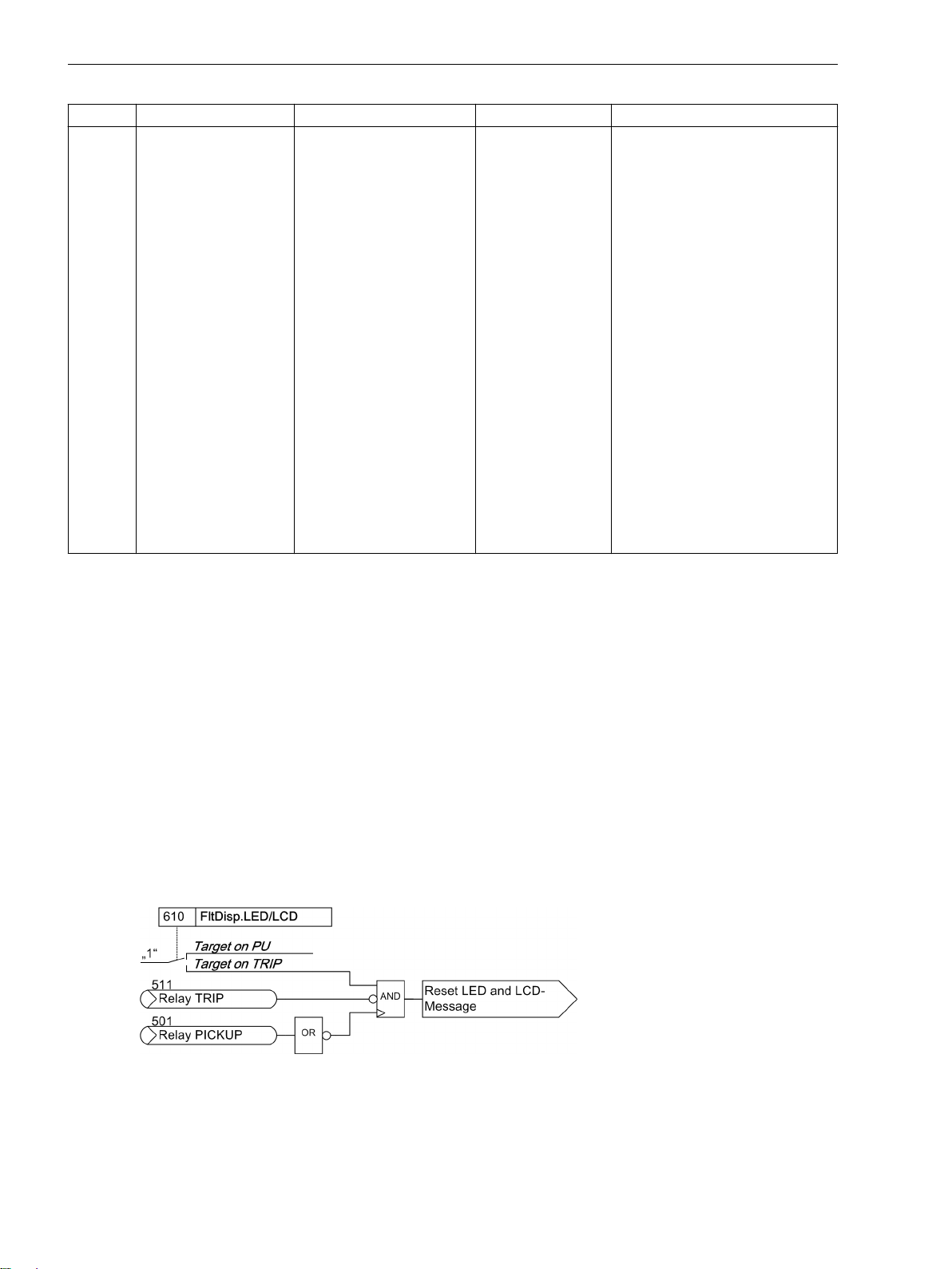
Command-Dependent Messages "No Trip – No Flag"
The storage of indications assigned to local LEDs and the availability of spontaneous indications can be made
dependent on whether the device has issued a trip command. This information is then not issued if during a
system disturbance one or more protection functions have picked up but the 7RW80 did not trip because the
fault was cleared by another device (e.g. on another line). These messages are then limited to faults in the line
to be protected.
The following figure illustrates the generation of the reset command for stored indications. The instant the
device drops out, the presetting of parameter 610 FltDisp.LED/LCD decides whether the new fault
remains stored or is reset.
[dw_ruecksetzbefehl-fuer-n-speicher-led-lcd-meld, 1, en_US]
Figure 2-1 Creation of the reset command for the latched LED and LCD messages
26 SIPROTEC 4, 7RW80, Manual
C53000-G1140-C233-4, Edition 07.2018
Page 27

Spontaneous Messages on the Display
You can determine whether or not the most important data of a fault event is displayed automatically after
the fault has occurred (see also Subsection "Fault Messages" in Section "Auxiliary Functions").
Functions
2.1 General
2.1.2.2
Setting Notes
Fault Messages
A new pickup of a protection function generally turns off any previously set light displays so that only the
latest fault is displayed at any one time. It can be selected whether the stored LED displays and the spontaneous messages on the display appear after the new pickup or only after a new trip signal is issued. In order to
select the desired mode of display, select the Device submenu in the SETTINGS menu. Under address 610
FltDisp.LED/LCD the two options Target on PU and Target on TRIP ("No trip – no flag") can be
selected.
For devices with graphic display, use parameter 611 Spont. FltDisp. to specify whether a spontaneous
fault message should appear automatically on the display (YES) or not (NO). For devices with text display such
indications will appear after a system fault in any case.
Selection of Default Display
The start page of the default display appearing after startup of the device can be selected in the device data
via parameter640 Start image DD. The pages available for each device version are listed in the Appendix
D Default Settings and Protocol-dependent Functions.
2.1.2.3
Addr.
Settings
Parameter Setting Options Default Setting Comments
610 FltDisp.LED/LCD Target on PU
Target on TRIP
611 Spont. FltDisp. YES
NO
640 Start image DD image 1
image 2
image 3
Target on PU Fault Display on LED / LCD
NO Spontaneous display of flt.annun-
ciations
image 1 Start image Default Display
2.1.2.4
No.
Information List
Information Type of
Comments
Information
- >Light on SP >Back Light on
- Reset LED IntSP Reset LED
- DataStop IntSP Stop data transmission
- Test mode IntSP Test mode
- Feeder gnd IntSP Feeder GROUNDED
- Brk OPENED IntSP Breaker OPENED
- HWTestMod IntSP Hardware Test Mode
- SynchClock IntSP_Ev Clock Synchronization
- Distur.CFC OUT Disturbance CFC
1 Not configured SP No Function configured
2 Non Existent SP Function Not Available
3 >Time Synch SP_Ev >Synchronize Internal Real Time Clock
5 >Reset LED SP >Reset LED
15 >Test mode SP >Test mode
SIPROTEC 4, 7RW80, Manual 27
C53000-G1140-C233-4, Edition 07.2018
Page 28

Functions
2.1 General
No. Information Type of
Information
16 >DataStop SP >Stop data transmission
51 Device OK OUT Device is Operational and Protecting
52 ProtActive IntSP At Least 1 Protection Funct. is Active
55 Reset Device OUT Reset Device
56 Initial Start OUT Initial Start of Device
67 Resume OUT Resume
68 Clock SyncError OUT Clock Synchronization Error
69 DayLightSavTime OUT Daylight Saving Time
70 Settings Calc. OUT Setting calculation is running
71 Settings Check OUT Settings Check
72 Level-2 change OUT Level-2 change
73 Local change OUT Local setting change
110 Event Lost OUT_Ev Event lost
113 Flag Lost OUT Flag Lost
125 Chatter ON OUT Chatter ON
140 Error Sum Alarm OUT Error with a summary alarm
160 Alarm Sum Event OUT Alarm Summary Event
177 Fail Battery OUT Failure: Battery empty
178 I/O-Board error OUT I/O-Board Error
181 Error A/D-conv. OUT Error: A/D converter
191 Error Offset OUT Error: Offset
193 Alarm NO calibr OUT Alarm: NO calibration data available
236.2127 BLK. Flex.Fct. IntSP BLOCK Flexible Function
301 Pow.Sys.Flt. OUT Power System fault
302 Fault Event OUT Fault Event
303 sens Gnd flt OUT sensitive Ground fault
320 Warn Mem. Data OUT Warn: Limit of Memory Data exceeded
321 Warn Mem. Para. OUT Warn: Limit of Memory Parameter exceeded
322 Warn Mem. Oper. OUT Warn: Limit of Memory Operation exceeded
323 Warn Mem. New OUT Warn: Limit of Memory New exceeded
502 Relay Drop Out SP Relay Drop Out
510 Relay CLOSE SP General CLOSE of relay
545 PU Time VI Time from Pickup to drop out
546 TRIP Time VI Time from Pickup to TRIP
10080 Error Ext I/O OUT Error Extension I/O
10081 Error Ethernet OUT Error Ethernet
10083 Error Basic I/O OUT Error Basic I/O
Comments
2.1.3
2.1.3.1
28 SIPROTEC 4, 7RW80, Manual
Power System Data 1
Functional Description
The device requires certain basic data regarding the protected equipment so that the device can adapt to its
desired application. These may be, for instance, nominal power system and transformer data, measured quantity polarities and their physical connections, breaker properties (where applicable) etc. There are also certain
parameters that are common to all functions, i.e. not associated with a specific protection, control or monitoring function. The following section discusses these parameters.
C53000-G1140-C233-4, Edition 07.2018
Page 29

Functions
2.1 General
2.1.3.2
Setting Notes
General
Some P.System Data 1 can be entered directly at the device. See Section 2.14 Notes on Device Operation
for more information regarding this topic.
In DIGSI double-click Settings to open the corresponding dialog box. In doing so, a dialog box with tabs will
open under P.System Data 1 where individual parameters can be configured. The following descriptions
are therefore structured according to these tabs.
Rated Frequency (Power System)
The nominal frequency of the system is set under the Address 214 Rated Frequency. The factory presetting in accordance with the model need only be changed if the device will be employed for a purpose other
than that which was planned when ordering.
In the US device versions (ordering data position 10= C), parameter 214 is preset to 60 Hz. 214.
Voltage Connection (Power System)
Address 213 specifies how the voltage transformers are connected.
VT Connect. 3ph = Van, Vbn, Vcn means that the three phase voltages are wye connected, i.e. the
three phase-to-ground voltages are measured.ground.
VT Connect. 3ph = Vab, Vbc, VGnd means that two phase-to-phase voltages (open delta voltage) and
the displacement voltage V
VT Connect. 3ph = Vab, Vbc means that two phase-to-phase voltages (open delta voltage) are
connected. The third voltage transformer of the device is not used.
VT Connect. 3ph = Vab, Vbc, Vx means that two phase-to-phase voltages (open delta voltage) are
connected. Furthermore, any third voltage Vx is connected that is used exclusively for the flexible protection
functions. The transformer nominal voltages for Vx are set at address 232 and 233.
VT Connect. 3ph = Vab, Vbc, VSyn means that two phase-to-phase voltages (open delta voltage) and
the reference voltage for V
device is used.
VT Connect. 3ph = Vph-g, VSyn is used if the synchronization function of the device is used and only
phase-to-ground voltages are available for the protected object to be synchronized. One of these voltages is
connected to the first voltage transformer; the reference voltage V
former.
The selection of the voltage transformer connection affects the operation of all device functions that require
voltage input.
The settings Vab, Vbc or Vab, Vbc, Vx or Vab, Vbc, VSyn or Vph-g, VSyn do not allow determining
the zero sequence voltage. The associated protection functions are inactive in this case.
The table gives an overview of the functions that can be activated for the corresponding connection type
(depends also on the ordering number). The functions which are not shown are available for all connection
types.
are connected.
GND
are connected. This setting is enabled if the synchronization function of the
SYN
is connected to the third voltage trans-
SYN
Table 2-1
Connection Types of the Voltage Transformers
Connection type Synchronization
Van, Vbn, Vcn
Vab, Vbc, VGnd
Vab, Vbc
Vab, Vbc, Vx
Vab, Vbc, VSyn
Vph-g, VSyn
no
no
no
no
yes
yes
Measured values, which due to the chosen voltage connection cannot be calculated, will be displayed as dots.
SIPROTEC 4, 7RW80, Manual 29
C53000-G1140-C233-4, Edition 07.2018
Page 30
Functions
2.1 General
The Appendix provides some connection examples for all connection types atC Connection Examples.
Nominal Values of Voltage Transformers (VTs)
At addresses 202 Vnom PRIMARY and 203 Vnom SECONDARY, information is entered regarding the primary
nominal voltage and secondary nominal voltage (phase-to-phase) of the connected voltage transformers.
Transformation Ratio of Voltage Transformers (VTs)
Address 206 Vph / Vdelta informs the device of the adjustment factor between the phase voltage and the
displacement voltage. This information is relevant for the processing of ground faults (in grounded systems
and ungrounded systems), for the operational measured value VN and measured-variable monitoring.
If the voltage transformer set provides open delta windings and if these windings are connected to the device,
this must be specified accordingly in address 213 (see above margin heading “Voltage Connection”). Since the
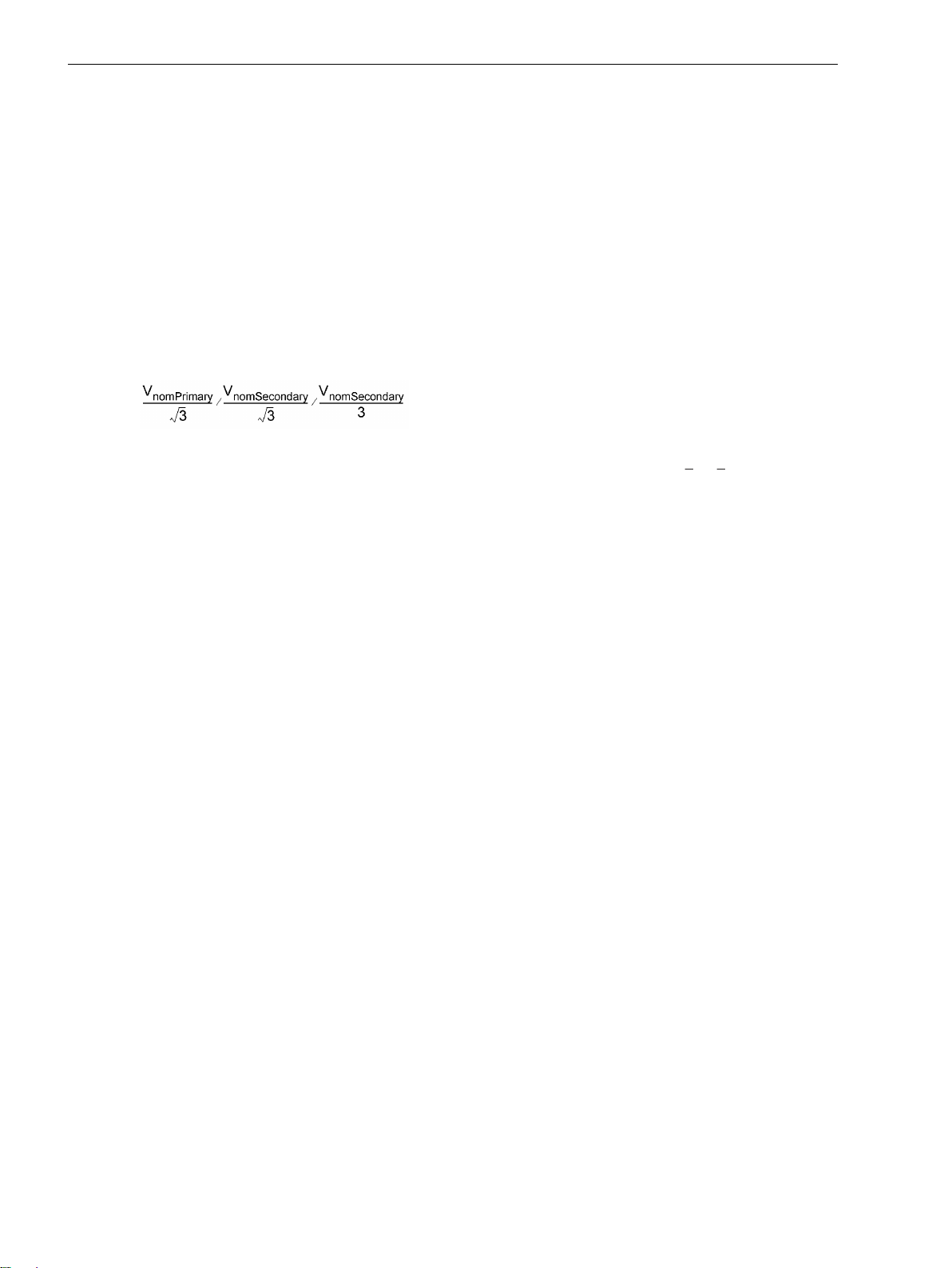
voltage transformer ratio is normally as follows:
[uebersetzung-spannungswandler-020313-kn, 1, en_US]
the factor V
(secondary voltage, address 206 Vph / Vdelta) must be set to 3/ √3 = √3 = 1.73 which
ph/VN
must be used if the VN voltage is connected. For other transformation ratios, i.e. the formation of the
displacement voltage via an interconnected transformer set, the factor must be corrected accordingly.
Please take into consideration that also the calculated secondary V0-voltage is divided by the value set in
address 206. Thus, even if the V0-voltage is not connected, address 206 has an impact on the secondary
operational measured value VN.
If Vab, Vbc, VGnd is selected as voltage connection type, parameter Vph / Vdelta is used to calculate
the phase-to-ground voltages and is therefore important for the protection function. With voltage connection
type Van, Vbn, Vcn, this parameter is used only to calculate the operational measured value of the secondary voltage VN.
Trip and Close Command Duration (Breaker)
In address 210 the minimum trip command duration TMin TRIP CMD is set. This setting applies to all protection functions that can initiate tripping.
In address 211 the maximum close command duration TMax CLOSE CMD is set. It applies to the integrated
reclosing function. It must be set long enough to ensure that the circuit breaker has securely closed. An excessive duration causes no problem since the closing command is interrupted in the event another trip is initiated
by a protection function.
Pickup Thresholds of the Binary Inputs (Thresholds BI)
At address 220 Threshold BI 1 to 226 Threshold BI 7 you can set the pickup thresholds of the binary
inputs of the device. The settings Thresh. BI 176V, Thresh. BI 88V or Thresh. BI 19V are possible.
Voltage Protection (Protection Operating Quantities)
In a three-phase connection, the fundamental harmonic of the three phase-to-phase voltages (Vphph) or
phase-ground voltages (Vph-n) or the positive sequence voltage (V1) or the negative sequence voltage (V2)
is supplied to the overvoltage protection elements.
In three-phase connection, undervoltage protection relies either on the positive sequence voltage (V1) or the
phase-to-phase voltages (Vphph) or the phase-to-ground voltages (Vph-n).
This is configured by setting the parameter value in address 614 OP. QUANTITY 59 and 615 OP. QUAN-
TITY 27.
Via Parameter 5009 59 Phases and 5109 27 Phases you may configure which measured quantity is to be
evaluated (All phases or Largest phase or Smallest phase).
30 SIPROTEC 4, 7RW80, Manual
C53000-G1140-C233-4, Edition 07.2018
Page 31

i
i
i
i
Functions
2.1 General
With single-phase voltage transformers, a direct comparison of the measured quantities with the threshold
values is carried out and the parameterization of the characteristic quantity switchover is ignored.
NOTE
If parameter 213 VT Connect. 3ph is set to Vph-g, VSyn, the voltage measured by voltage transformer 1 is always used for voltage protection. Then parameters 614 and 615 are not available.
NOTE
If parameter 213 VT Connect. 3ph is set to Vab, Vbc, VSyn or Vab, Vbc or Vab, Vbc, Vx, the
setting option Vph-n for parameter 614 and 615 is not available.
2.1.3.3
Addr. Parameter Setting Options Default Setting Comments
202 Vnom PRIMARY 0.10 .. 800.00 kV 20.00 kV Rated Primary Voltage
203 Vnom SECONDARY 34 .. 225 V 100 V Rated Secondary Voltage (L-L)
206A Vph / Vdelta 1.00 .. 3.00 1.73 Matching ratio Phase-VT To Open-
209 PHASE SEQ. A B C
210A TMin TRIP CMD 0.01 .. 32.00 sec 0.15 sec Minimum TRIP Command Duration
211A TMax CLOSE CMD 0.01 .. 32.00 sec 1.00 sec Maximum Close Command Dura-
213 VT Connect. 3ph Van, Vbn, Vcn
214 Rated Frequency 50 Hz
220 Threshold BI 1 Thresh. BI 176V
221 Threshold BI 2 Thresh. BI 176V
222 Threshold BI 3 Thresh. BI 176V
223 Threshold BI 4 Thresh. BI 176V
224 Threshold BI 5 Thresh. BI 176V
Settings
Addresses which have an appended “A” can only be changed with DIGSI, under “Additional Settings”.
Delta-VT
A B C Phase Sequence
A C B
tion
Van, Vbn, Vcn VT Connection, three-phase
Vab, Vbc, VGnd
Vab, Vbc, VSyn
Vab, Vbc
Vph-g, VSyn
Vab, Vbc, Vx
50 Hz Rated Frequency
60 Hz
Thresh. BI 176V Threshold for Binary Input 1
Thresh. BI 88V
Thresh. BI 19V
Thresh. BI 176V Threshold for Binary Input 2
Thresh. BI 88V
Thresh. BI 19V
Thresh. BI 176V Threshold for Binary Input 3
Thresh. BI 88V
Thresh. BI 19V
Thresh. BI 176V Threshold for Binary Input 4
Thresh. BI 88V
Thresh. BI 19V
Thresh. BI 176V Threshold for Binary Input 5
Thresh. BI 88V
Thresh. BI 19V
SIPROTEC 4, 7RW80, Manual 31
C53000-G1140-C233-4, Edition 07.2018
Page 32

Functions
2.1 General
Addr. Parameter Setting Options Default Setting Comments
225 Threshold BI 6 Thresh. BI 176V
Thresh. BI 176V Threshold for Binary Input 6
Thresh. BI 88V
Thresh. BI 19V
226 Threshold BI 7 Thresh. BI 176V
Thresh. BI 176V Threshold for Binary Input 7
Thresh. BI 88V
Thresh. BI 19V
232 VXnom PRIMARY 0.10 .. 800.00 kV 20.00 kV Rated Primary Voltage X
233 VXnom SECONDARY 100 .. 225 V 100 V Rated Secondary Voltage X
614A OP. QUANTITY 59 Vphph
Vph-n
Vphph Opera. Quantity for 59 Overvolt.
Prot.
V1
V2
615A OP. QUANTITY 27 V1
Vphph
V1 Opera. Quantity for 27 Undervolt.
Prot.
Vph-n
2.1.3.4
No. Information Type of
Information List
Comments
Information
5145 >Reverse Rot. SP >Reverse Phase Rotation
5147 Rotation ABC OUT Phase rotation ABC
5148 Rotation ACB OUT Phase rotation ACB
2.1.4
Oscillographic Fault Records
The Multifunctional Protection with Control 7RW80 is equipped with a fault record memory. The instantaneous values of the measured values
vA, vB, vC, vA2, vB3, vC1, vN, vX, v
ph-n
, v
SYN
(voltages depending on connection) are sampled at intervals of 1.0 ms (at 50 Hz) and stored in a revolving
buffer (20 samples per cycle). In the event of a fault, the data are recorded for a set period of time, but not for
more than 5 seconds. A maximum of 8 faults can be recorded in this buffer. The fault record memory is automatically updated with every new fault, so no acknowledgment for previously recorded faults is required. In
addition to protection pickup, the recording of the fault data can also be started via a binary input or via the
serial interface.
2.1.4.1
Functional Description
The data of a fault event can be read out via the device interface and evaluated with the help of the SIGRA 4
graphic analysis software. SIGRA 4 graphically represents the data recorded during the fault event and also
calculates additional information from the measured values. Currents and voltages can be presented either as
primary or as secondary values. Signals are additionally recorded as binary tracks (marks), e.g. "pickup", "trip".
If port B of the device has been configured correspondingly, the fault record data can be imported by a central
controller via this interface and evaluated. Currents and voltages are prepared for a graphic representation.
Signals are additionally recorded as binary tracks (marks), e.g. "pickup", "trip".
The retrieval of the fault data by the central controller takes place automatically either after each protection
pickup or after a tipping.
Depending on the selected type of connection of the voltage transformers (address 213 VT Connect. 3ph),
the following measured values are recorded in the fault record:
32 SIPROTEC 4, 7RW80, Manual
C53000-G1140-C233-4, Edition 07.2018
Page 33

i
i
2.1 General
Voltage connection
Van, Vbn, Vcn Vab, Vbc,
VGnd
v
AB
v
BC
v
CA
v
A
v
B
v
C
v yes
v
en
v
SYN
v
x
yes yes yes yes yes
yes yes yes yes yes
yes yes yes yes yes
yes yes
yes yes
yes yes
yes yes
NOTE
The signals used for the binary tracks can be allocated in DIGSI.
Vab, Vbc Vab, Vbc, Vx Vab, Vbc, VSyn Vph-g, VSyn
yes yes
yes
Functions
2.1.4.2
Configuration
Setting Notes
Fault recording (waveform capture) will only take place if address 104 OSC. FAULT REC. is set to Enabled.
Other settings pertaining to fault recording (waveform capture) are found in the Osc. Fault Rec.
submenu of the SETTINGS menu. Waveform capture makes a distinction between the trigger instant for an
oscillographic record and the criterion to save the record (address 401 WAVEFORMTRIGGER). Normally, the
trigger is the pickup of a protection element, i.e. the time 0 is defined as the instant the first protection function picks up. The criterion for saving may be both the device pickup (Save w. Pickup) or the device trip
(Save w. TRIP). A trip command issued by the device can also be used as trigger instant (Start w.
TRIP), in this case it is also the saving criterion.
A fault event starts with the pickup by any protection function and ends when the last pickup of a protection
function has dropped out. Usually this is also the extent of a fault recording (address 402 WAVEFORM DATA =
Fault event). If automatic reclosing is performed by external equipments, the entire system fault — with
several reclosing attempts if necessary — can be recorded until the fault has been cleared for good (address
402 WAVEFORM DATA = Pow.Sys.Flt.). This facilitates the representation of the entire system fault history,
but also consumes storage capacity during the automatic reclosing dead time(s).
The actual storage time begins at the pre-fault time PRE. TRIG. TIME (address 404) ahead of the reference
instant, and ends at the post-fault time POST REC. TIME (address 405) after the storage criterion has reset.
The maximum storage duration of each fault record (MAX. LENGTH) is entered at address 403. Recording per
fault must not exceed 5 seconds. In maximum 8 records can be saved altogether with a maximum total time
of 20 s 18 s .
An oscillographic record can be triggered by a status change of a binary input, or from a PC via the operator
interface. Storage is then triggered dynamically. The length of the fault recording is set in address 406 BinIn
CAPT.TIME (but not longer than MAX. LENGTH, address 403). Pre-fault and post-fault times will add to this.
If the binary input time is set to ∞, the length of the record equals the time that the binary input is activated
(static), but not longer than the MAX. LENGTH (address 403).
SIPROTEC 4, 7RW80, Manual 33
C53000-G1140-C233-4, Edition 07.2018
Page 34

Functions
2.1 General
2.1.4.3
Addr. Parameter Setting Options Default Setting Comments
401 WAVEFORMTRIGGER Save w. Pickup
402 WAVEFORM DATA Fault event
403 MAX. LENGTH 0.30 .. 5.00 sec 2.00 sec Max. length of a Waveform
404 PRE. TRIG. TIME 0.05 .. 0.50 sec 0.10 sec Captured Waveform Prior to
405 POST REC. TIME 0.05 .. 0.50 sec 0.10 sec Captured Waveform after Event
406 BinIn CAPT.TIME 0.10 .. 5.00 sec 0.50 sec Capture Time via Binary Input
2.1.4.4
No. Information Type of
- FltRecSta IntSP Fault Recording Start
4 >Trig.Wave.Cap. SP >Trigger Waveform Capture
203 Wave. deleted OUT_Ev Waveform data deleted
30053 Fault rec. run. OUT Fault recording is running
Settings
Save w. Pickup Waveform Capture
Save w. TRIP
Start w. TRIP
Fault event Scope of Waveform Data
Pow.Sys.Flt.
Capture Record
Trigger
Information List
Comments
Information
2.1.5
2.1.5.1
Changing Setting Groups
2.1.5.2
General
Settings Groups
Up to four different setting groups can be created for establishing the device's function settings.
Functional Description
During operation the user can switch back and forth setting groups locally, via the operator panel, binary
inputs (if so configured), the service interface using a personal computer, or via the system interface. For
reasons of safety it is not possible to change between setting groups during a power system fault.
A setting group includes the setting values for all functions that have been selected as Enabled during
configuration (see Section 2.1.1.2 Setting Notes). In 7RW80 relays, four independent setting groups (A to D)
are available. While setting values may vary, the selected functions of each setting group remain the same.
Setting Notes
If setting group change option is not required, Group A is the default selection. Then, the rest of this section is
not applicable.
If the changeover option is desired, group changeover must be set to Grp Chge OPTION = Enabled
(address 103) when the function extent is configured. For the setting of the function parameters, each of the
required setting groups A to D (a maximum of 4) must be configured in sequence. The SIPROTEC 4 System
Description gives further information on how to copy setting groups or reset them to their status at delivery
and also how to change from one setting group to another.
Section 3.1 Mounting and Connections of this manual tells you how to change between several setting groups
externally via binary inputs.
34 SIPROTEC 4, 7RW80, Manual
C53000-G1140-C233-4, Edition 07.2018
Page 35

Functions
2.1 General
2.1.5.3
Addr. Parameter Setting Options Default Setting Comments
302 CHANGE Group A
2.1.5.4
No. Information Type of
- P-GrpA act IntSP Setting Group A is active
- P-GrpB act IntSP Setting Group B is active
- P-GrpC act IntSP Setting Group C is active
- P-GrpD act IntSP Setting Group D is active
7 >Set Group Bit0 SP >Setting Group Select Bit 0
8 >Set Group Bit1 SP >Setting Group Select Bit 1
2.1.6
Settings
Group A Change to Another Setting Group
Group B
Group C
Group D
Binary Input
Protocol
Information List
Comments
Information
Power System Data 2
2.1.6.1
Applications
2.1.6.2
Rated Values of the System
2.1.6.3
Addr.
1101 FullScaleVolt. 0.10 .. 800.00 kV 20.00 kV Measurem:FullScale-
2.1.6.4
Functional Description
The general protection data (P.System Data 2) include settings associated with all functions rather than a
specific protection or monitoring function. In contrast to the P.System Data 1 as discussed before, they
can be changed with the setting group.
When the primary reference voltage and the primary reference current of the protected object are set, the
device is able to calculate and output the operational measured value percentage.
Setting Notes
At address 1101 FullScaleVolt. the reference voltage (phase-to-phase) of the monitored equipment is
entered. If these reference values match the primary values of the voltage transformer, they correspond to the
setting at Address 202 (Section 2.1.3.2 Setting Notes). They are generally used to show values referenced to
full scale.
Settings
Parameter Setting Options Default Setting Comments
Voltage(Equipm.rating)
Information List
No.
126 ProtON/OFF IntSP Protection ON/OFF (via system port)
SIPROTEC 4, 7RW80, Manual 35
C53000-G1140-C233-4, Edition 07.2018
Information Type of
Information
Comments
Page 36

Functions
2.1 General
No. Information Type of
Information
356 >Manual Close SP >Manual close signal
501 Relay PICKUP OUT Relay PICKUP
511 Relay TRIP OUT Relay GENERAL TRIP command
561 Man.Clos.Detect OUT Manual close signal detected
4601 >52-a SP >52-a contact (OPEN, if bkr is open)
4602 >52-b SP >52-b contact (OPEN, if bkr is closed)
2.1.7
2.1.7.1
2.1.7.2
Interface Selection
EN100-Module
Functional Description
The Ethernet EN100-Modul enables integration of the 7RW80 in 100-Mbit communication networks in control
and automation systems with the protocols according to IEC 61850 standard. This standard permits uniform
communication of the devices without gateways and protocol converters. Even when installed in heterogeneous environments, SIPROTEC 4 relays therefore provide for open and interoperable operation. Parallel to the
process control integration of the device, this interface can also be used for communication with DIGSI and for
inter-relay communication via GOOSE.
Setting Notes
Comments
No special settings are required for operating the Ethernet system interface module (IEC 1850, Ethernet
EN100-Modul). If the ordered version of the device is equipped with such a module, it is automatically allo-
cated to the interface available for it, namely Port B.
2.1.7.3
No.
009.0100 Failure Modul IntSP Failure EN100 Modul
009.0101 Fail Ch1 IntSP Failure EN100 Link Channel 1 (Ch1)
009.0102 Fail Ch2 IntSP Failure EN100 Link Channel 2 (Ch2)
Information List
Information Type of
Information
Comments
36 SIPROTEC 4, 7RW80, Manual
C53000-G1140-C233-4, Edition 07.2018
Page 37

Functions
2.2 Voltage Protection 27, 59
2.2
2.2.1
Connection/Measured Values
Voltage Protection 27, 59
Voltage protection has the task to protect electrical equipment against undervoltage and overvoltage. Both
operational states are abnormal as overvoltage may cause for example insulation problems or undervoltage
may cause stability problems.
There are three elements each available for overvoltage protection and undervoltage protection.
Applications
Abnormally high voltages often occur e.g. in low loaded, long distance transmission lines, in islanded
•
systems when generator voltage regulation fails, or after full load rejection of a generator from the
system.
The undervoltage protection function detects voltage collapses on transmission lines and electrical
•
machines and prevents inadmissible operating states and a possible loss of stability.
Measurement Principle
The voltages supplied to the device may correspond to the three phase-to-ground voltages V
the two phase-to-phase voltages (V
of a single-phase connection - any phase-to-ground voltage. The connection type has been specified during
the configuration in parameter 213 VT Connect. 3ph (see Section 2.1.3.2 Setting Notes).
The following table indicates which voltages can be evaluated by the function. The settings for this are made
in the P.System Data 1 (see Section 2.1.3.2 Setting Notes). Furthermore, it is indicated to which value the
threshold must be set. All voltages are fundamental frequency values.
A-N
, V
) and the displacement voltage (ground voltage VN) or - in the case
A-B
B-C
, V
B-N
, V
C-N
or
Table 2-2
Connection, threephase
(parameter213)
Overvoltage
Van, Vbn, Vcn
Vab, Vbc, VGnd
Vab, Vbc
Vab, Vbc, VSyn
Vab, Vbc, Vx
Vph-g, VSyn
Undervoltage
Van, Vbn, Vcn
Voltage protection, selectable voltages
Selectable voltage
parameter 614/ 615
Vphph (largest phase-to-phase voltage) Phase-to-phase voltage
Vph-n ((largest phase-to-ground voltage) Phase-to-ground voltage
V1(positive sequence voltage) Positive sequence voltage calculated
V2 (negative sequence voltage) Negative sequence voltage
Vphph (largest phase-to-phase voltage) Leiter-Leiter-Spannung
V1(positive sequence voltage) Positive sequence voltage
V2 (negative sequence voltage) Negative sequence voltage
None (direct evaluation of the voltage connected to
voltage input 1)
Vphph (smallest phase-to-phase voltage) Phase-to-phase voltage
Vph-n (smallest phase-to-ground voltage) Phase-to-ground voltage
V1 (positive sequence voltage) Positive sequence voltage· √3
Threshold to be set as
from
phase-to-groundvoltage or
phase-tophase voltage / √3
Direct voltage value
SIPROTEC 4, 7RW80, Manual 37
C53000-G1140-C233-4, Edition 07.2018
Page 38

Functions
2.2 Voltage Protection 27, 59
Connection, threephase
(parameter213)
Vab, Vbc, VGnd
Vab, Vbc
Vab, Vbc, VSyn
Vab, Vbc, Vx
Vph-g, VSyn
The positive and negative sequence voltages stated in the table are calculated from the phase-to-ground
voltages.
2.2.2
Overvoltage Protection 59
Function
The overvoltage protection includes three elements (59-1 PICKUP, 59-2 PICKUP, 59 Vp>). In case of a
high overvoltage, the switchoff is performed with a short-time delay, whereas in case of lower overvoltages,
the switchoff is performed with a longer time delay. When an adjustable setting is exceeded, the 59 element
picks up, and after an adjustable time delay elapses, initiates a trip signal. The time delay is not dependent on
the magnitude of the overvoltage.
Additionally the element 59 Vp> allows the definition of a user defined tripping curve with 20 value pairs
(voltage/ time). Parameterization is done via DIGSI.
For both over-voltage elements 59-1 PICKUP, 59-2 PICKUP the dropout ratio (= V
parameterized.
A parameter is set to specify, whether the measured values of all phases or only phases with the highest value
for monitoring are being used.
The following figure shows the logic diagram of the overvoltage protection function.
Selectable voltage
Threshold to be set as
parameter 614/ 615
Vphph (smallest phase-to-phase voltage) Phase-to-phase voltage
V1 ((positive sequence voltage) Positive sequence voltage· √3
None (direct evaluation of the voltage connected to
Direct voltage value
voltage input 1)
dropout/Vpickup
) can be
38 SIPROTEC 4, 7RW80, Manual
C53000-G1140-C233-4, Edition 07.2018
Page 39

Functions
2.2 Voltage Protection 27, 59
[7rw80-ueberspgs-schutz-20100716, 1, en_US]
2.2.3
Figure 2-2
Undervoltage Protection 27
Logic diagram of the overvoltage protection
Funktion
Undervoltage protection consists of three elements (27-1 PICKUP, 27-2 PICKUP, 27 Vp<). Therefore, tripping can be time-graded depending on how severe voltage collapses are. Voltage thresholds and time delays
can be set individually for both elements 27-1 PICKUP and 27-2 PICKUP.
Additionally the element27 Vp< allows the definition of a user defined tripping curve with 20 value pairs
(voltage/ time). Parameterization is done via DIGSI.
SIPROTEC 4, 7RW80, Manual 39
C53000-G1140-C233-4, Edition 07.2018
Page 40

Functions
2.2 Voltage Protection 27, 59
For both under-voltage elements 27-1 PICKUP and 27-2 PICKUP the dropout ratio (= V
dropout/Vpickup
) can be
parameterized.
A parameter is set to specify, whether the measured values of all phases or only phases with the lowest value
for monitoring are being used.
The undervoltage protection works in an additional frequency range. This ensures that the protective function
is preserved even when it is applied e.g. as motor protection in context with decelerating motors. However,
the r.m.s. value of the positive-sequence voltage component is considered too small when severe frequency
deviations exist. This function therefore exhibits an overfunction.
Figure 2-3 shows a typical voltage profile during a fault for source side connection of the voltage trans-
formers. After the voltage has decreased below the pickup setting, tripping is initiated after time delay 27-1
DELAY. As long as the voltage remains below the drop out setting, reclosing is blocked. Only after the fault
has been cleared, i.e. when the voltage increases above the drop out level, the element drops out and allows
reclosing of the circuit breaker.
[stoerfallverlauf-speiseseitig-20100525, 1, en_US]
Figure 2-3 Typical fault profile for supply-side connection of the voltage transformers
The following Figure shows the logic diagram of the undervoltage protection function.
40 SIPROTEC 4, 7RW80, Manual
C53000-G1140-C233-4, Edition 07.2018
Page 41

Functions
2.2 Voltage Protection 27, 59
[7rw80-unterspgs-schutz-20100525, 1, en_US]
Logic diagram of the undervoltage protection
2.2.4
Figure 2-4
Setting Notes
General
Voltage protection is only in effect and accessible if address 150 27/59 is set to Enabled during configuration of protective functions. If the function is not required Disabled is set.
The voltage to be evaluated is selected in Power System Data 1 (see Chapter 2.2 Voltage Protection 27, 59,
Table 2-2).
Overvoltage protection can be turned ON or OFF or set to Alarm Only at address 5001 FCT 59.
SIPROTEC 4, 7RW80, Manual 41
C53000-G1140-C233-4, Edition 07.2018
Page 42

Functions
2.2 Voltage Protection 27, 59
Undervoltage protection can be turned ON or OFF or set to Alarm Only at address 5101 FCT 27.
With the protection function ON tripping, fault record and fault recording will occur when limit values were
exceeded and after time delays expired.
When setting Alarm Only no trip command is given, no fault is recorded and no spontaneous fault annunci-
ation is shown on the display.
For over-voltage and under-voltage protection user-defined curves with 20 value pairs (voltage/time) may be
configured. Usage of a curve has to be activated at address 5035 Pickup - Time for the element 59 Vp>
and at address 5133 Pickup - Time for the element 27 Vp<.
Overvoltage Protection (59-1, 59-2) with phase-to-phase / phase-to-ground voltage
For over-voltage protection with phase-to-phase or phase-to-ground voltages you have to configure at address
5009 59 Phases the measured quantity that is to be evaluated for the over voltage protection. While being
configuredAll phases all voltages have to exceed their threshold. AtLargest phase only one voltage has
to exceed its threshold.
The threshold values are set in the value to be evaluated (see Chapter 2.2 Voltage Protection 27, 59,
Table 2-2).
Overvoltage protection includes three elements. The pickup value of the lower threshold is set at address
5002 or 5003, 59-1 PICKUP, (depending on if the phase-to-ground or the phase-to-phase voltages are
connected), while time delay is set at address 5004, 59-1 DELAY (a longer time delay). The pickup value of
the upper element is set at address 5005 or 5006, 59-2 PICKUP, while the time delay is set at address 5007,
59-2 DELAY (a short time delay). A third element can be activated at address 5031 59 Vp>, which works
with a user-defined curve (address 5035).
There are not clear cut procedures on how to set the pickup values. However, since the overvoltage function is
primarily intended to prevent insulation damage on equipment and loads, the setting value 5002 , 5003 59-1
PICKUP should be set between 110 % and 115 % of nominal voltage, and setting value 5005, 5006 59-2
PICKUP should be set to about 130 % of nominal voltage.
The time delays of the overvoltage elements are entered at addresses 5004 59-1 DELAY, 5007 59-2 DELAY
and 5034 59 T Vp> and should be selected to allow the brief voltage spikes that are generated during
switching operations and to enable clearance of stationary overvoltages in time.
The option to choose between phase-to-ground and phase-to-phase voltage, allows voltage asymmetries (e.g.
caused by a ground fault) to be taken into account (phase-to-ground) or to remain unconsidered (phase–tophase) during evaluation.
Overvoltage Protection - Positive Sequence System V1
In a three-phase voltage transformer connection the positive sequence system can be evaluated for the overvoltage protection by means of configuring parameter 614 OP. QUANTITY 59 to V1. In this case, the
threshold values of the overvoltage protection must be set in parameters 5019 59-1 PICKUP V1 or 5020
59-2 PICKUP V1. A third element can be activated at address 5032 59 Vp> V1, which works with a userdefined curve (address 5035).
Overvoltage Protection - Negative Sequence System V2
In a three-phase transformer connection, parameter 614 OP. QUANTITY 59 can determine that the negative
sequence system V2 can be evaluated as a measured value for the overvoltage protection. The negative
sequence system detects voltage asymmetries.
Overvoltage protection includes three elements. Thus, with configuration of the negative system, a longer
time delay (Adresse 5004, 59-1 DELAY) may be assigned to the lower element (address 5015, 59-1
PICKUP V2) depending on whether phase-to-ground or phase-to-phase voltages are connected) and a
shorter time delay (address 5007, 59-2 DELAY) may be assigned to the upper element (Address 5016, 59-2
PICKUP V2). A third element can be activated at address 5033 59 Vp> V2, which works with a user-defined
curve (address 5035).
There are not clear cut procedures on how to set the pickup values 59-1 PICKUP V2 or 59-2 PICKUP V2,
as they depend on the respective station configuration.
42 SIPROTEC 4, 7RW80, Manual
C53000-G1140-C233-4, Edition 07.2018
Page 43

The time delays of the overvoltage elements are entered at addresses 5004 59-1 DELAY and 5007 59-2
DELAY, and should be selected in such manner that they make allowance for brief voltage peaks that are
generated during switching operations and also enable clearance of stationary overvoltages in due time.
Dropout Threshold of the Overvoltage Protection
The dropout thresholds of the 59-1 element and the 59-2 element can be configured via the dropout ratio r =
V
Dropout/VPickup
at addresses 5017 59-1 DOUT RATIO or 5018 59-2 DOUT RATIO. The following marginal
condition applies to r:
r · (configured pickup threshold) ≤ 150 V with connection of phase-to-phase voltages and phase-to-ground
voltages or
r · (configured pickup threshold) ≤ 260 V with calculation of the measured values from the connected voltages
(e.g. phase-to-phase voltages calculated from the connected phase-to-ground voltages).
The minimum hysteresis is 0.6 V.
Undervoltage Protection - Positive Sequence System V1
The positive sequence component (V1) can be evaluated for the undervoltage protection. Especially in case of
stability problems, their acquisition is advantageous because the positive sequence system is relevant for the
limit of the stable energy transmission. Concerning the pickup values there are no specific notes on how to set
them. However, because the undervoltage protection function is primarily intended to protect induction
machines from voltage dips and to prevent stability problems, the pickup values will usually be between 60 %
and 85 % of the nominal voltage.
The threshold value is multiplied as positive sequence voltage and set to √
nominal voltage.
Undervoltage protection with evaluation of the positive sequence componentscomprises two elements. The
pickup value of the lower threshold is set at address 5110 or 5111, 27-2 PICKUP (depending on the voltage
transformer connection, phase-to-ground or phase-to-phase), while time delay is set at address 5112, 27-2
DELAY (short time delay). The pickup value of the upper element is set at address 5102 or 5103, 27-1
PICKUP, while the time delay is set at address 5106, 27-1 DELAY (a somewhat longer time delay). Setting
these elements in this way allows the undervoltage protection function to closely follow the stability behavior
of the system.
The time settings should be selected such that tripping occurs in response to voltage dips that lead to unstable
operating conditions. On the other hand, the time delay should be long enough to avoid tripping on shortterm voltage dips.
Functions
2.2 Voltage Protection 27, 59
3, thus realizing the reference to the
Undervoltage Protection with Phase-to-phase or Phase-to-ground Voltages
For undervoltage protection with phase-to-phase or phase-to-ground voltages you have to configure at
address 5109 27 Phases the measured quantity that is to be evaluated for the undervoltage protection.
While being configured All phases all voltages have to underrun their threshold. At Smallest phase
only one voltage has to underrun its threshold.
The threshold values are set in the value to be evaluated (see Chapter 2.2 Voltage Protection 27, 59,
Table 2-2)
Undervoltage protection includes three elements. The pickup value of the lower threshold is set at address
5110 or 5111, 27-2 PICKUP (depending on the voltage transformer connection, phase-to-ground or
phaseto- phase), while time delay is set at address 5112, 27-2 DELAY (short time delay). The pickup value of
the upper element is set at address 5102 or 5103, 27-1 PICKUP, while the time delay is set at address 5106,
27-1 DELAY (a somewhat longer time delay). Setting these elements in this matter allows the undervoltage
protection function to closely follow the stability behaviour of the system. A third element can be activated at
address 5131 27 Vp<, which works with a user-defined curve (address 5133). The corresponding delay time
can be configured at address 5132 27 T Vp<.
The time settings should be selected such that tripping occurs in response to voltage dips that lead to unstable
operating conditions. On the other hand, the time delay should be long enough to avoid tripping on shortterm voltage dips.
SIPROTEC 4, 7RW80, Manual 43
C53000-G1140-C233-4, Edition 07.2018
Page 44

i
i
Functions
2.2 Voltage Protection 27, 59
Dropout Threshold of the Undervoltage Protection
The dropout thresholds of the 59-1 element and the 59-2 element can be parameterized via the dropout ratio
r = V
dropout/Vpickup
applies to r:
r · (configured pickup threshold) ≤ 130 V with connection of phase-to-phase voltages and phase-to-ground
voltages) or
r· (configured pickup threshold) ≤ 225 V with calculation of the measured values from the connected voltages
(e.g. calculated phase-to-phase voltages from the connected phase-to-ground voltages).
The minimum hysteresis is 0.6 V.
NOTE
If a setting is selected such that the dropout threshold (= pickup threshold · dropout ratio) results in a
greater value than 130 V/225 V, it will be limited automatically. No error message occurs.
(5113 27-1 DOUT RATIO or 5114 27-2 DOUT RATIO). The following marginal condition
2.2.5
Addr. Parameter Setting Options Default Setting Comments
5001 FCT 59 OFF
5002 59-1 PICKUP 20 .. 260 V 110 V 59-1 Pickup
5003 59-1 PICKUP 20 .. 150 V 110 V 59-1 Pickup
5004 59-1 DELAY 0.00 .. 100.00 sec 0.50 sec 59-1 Time Delay
5005 59-2 PICKUP 20 .. 260 V 120 V 59-2 Pickup
5006 59-2 PICKUP 20 .. 150 V 120 V 59-2 Pickup
5007 59-2 DELAY 0.00 .. 100.00 sec 0.50 sec 59-2 Time Delay
5009 59 Phases All phases
5015 59-1 PICKUP V2 2 .. 150 V 30 V 59-1 Pickup V2
5016 59-2 PICKUP V2 2 .. 150 V 50 V 59-2 Pickup V2
5017A 59-1 DOUT RATIO 0.90 .. 0.99 0.95 59-1 Dropout Ratio
5018A 59-2 DOUT RATIO 0.90 .. 0.99 0.95 59-2 Dropout Ratio
5019 59-1 PICKUP V1 20 .. 150 V 110 V 59-1 Pickup V1
5020 59-2 PICKUP V1 20 .. 150 V 120 V 59-2 Pickup V1
5030 59 Vp> 20 .. 260 V 110 V 59 Pickup Vp>
5031 59 Vp> 20 .. 150 V 110 V 59 Pickup Vp>
5032 59 Vp> V1 20 .. 150 V 110 V 59 Pickup Vp> V1
5033 59 Vp> V2 2 .. 150 V 30 V 59 Pickup Vp> V2
5034 59 T Vp> 0.1 .. 5.0 sec 5.0 sec 59 T Vp> Time Delay
5035 Pickup - Time 1.00 .. 20.00
5101 FCT 27 OFF
5102 27-1 PICKUP 10 .. 210 V 75 V 27-1 Pickup
5103 27-1 PICKUP 10 .. 120 V 45 V 27-1 Pickup
5106 27-1 DELAY 0.00 .. 100.00 sec 1.50 sec 27-1 Time Delay
Settings
Addresses which have an appended “A” can only be changed with DIGSI, under “Additional Settings”.
OFF 59 Overvoltage Protection
ON
Alarm Only
Largest phase Phases for 59
Largest phase
Pickup - Time
0.01 .. 999.00
OFF 27 Undervoltage Protection
ON
Alarm Only
44 SIPROTEC 4, 7RW80, Manual
C53000-G1140-C233-4, Edition 07.2018
Page 45

2.2 Voltage Protection 27, 59
Addr. Parameter Setting Options Default Setting Comments
5109 27 Phases Smallest phase
All phases
5110 27-2 PICKUP 10 .. 210 V 70 V 27-2 Pickup
5111 27-2 PICKUP 10 .. 120 V 40 V 27-2 Pickup
5112 27-2 DELAY 0.00 .. 100.00 sec 0.50 sec 27-2 Time Delay
5113A 27-1 DOUT RATIO 1.01 .. 3.00 1.20 27-1 Dropout Ratio
5114A 27-2 DOUT RATIO 1.01 .. 3.00 1.20 27-2 Dropout Ratio
5130 27 Vp< 10 .. 210 V 75 V 27 Pickup Vp<
5131 27 Vp< 10 .. 120 V 45 V 27 Pickup Vp<
5132 27 T Vp< 0.1 .. 5.0 sec 1.0 sec 27 T Vp< Time Delay
5133 Pickup - Time 0.05 .. 1.00
0.01 .. 999.00
All phases Phases for 27
Pickup - Time
Functions
2.2.6
No. Information Type of
234.2100 27, 59 blk IntSP 27, 59 blocked via operation
6503 >BLOCK 27 SP >BLOCK 27 undervoltage protection
6506 >BLOCK 27-1 SP >BLOCK 27-1 Undervoltage protection
6508 >BLOCK 27-2 SP >BLOCK 27-2 Undervoltage protection
6513 >BLOCK 59 SP >BLOCK 59 overvoltage protection
6530 27 OFF OUT 27 Undervoltage protection switched OFF
6531 27 BLOCKED OUT 27 Undervoltage protection is BLOCKED
6532 27 ACTIVE OUT 27 Undervoltage protection is ACTIVE
6533 27-1 picked up OUT 27-1 Undervoltage picked up
6534 27-1 PU CS OUT 27-1 Undervoltage PICKUP w/curr. superv
6537 27-2 picked up OUT 27-2 Undervoltage picked up
6538 27-2 PU CS OUT 27-2 Undervoltage PICKUP w/curr. superv
6539 27-1 TRIP OUT 27-1 Undervoltage TRIP
6540 27-2 TRIP OUT 27-2 Undervoltage TRIP
6565 59 OFF OUT 59 Overvoltage protection switched OFF
6566 59 BLOCKED OUT 59 Overvoltage protection is BLOCKED
6567 59 ACTIVE OUT 59 Overvoltage protection is ACTIVE
6568 59-1 picked up OUT 59-1 Overvoltage V> picked up
6570 59-1 TRIP OUT 59-1 Overvoltage V> TRIP
6571 59-2 picked up OUT 59-2 Overvoltage V>> picked up
6573 59-2 TRIP OUT 59-2 Overvoltage V>> TRIP
17370 >BLOCK Vp< SP >Block Undervoltage protection Vp<
17371 >BLOCK Vp> SP >Block Overvoltage protection Vp>
17372 Vp< picked up OUT Vp< Undervoltage picked up
17373 Vp> picked up OUT Vp> Overvoltage picked up
17374 Vp< TRIP OUT Vp< Undervoltage TRIP
17375 Vp> TRIP OUT Vp> Overvoltage TRIP
Information List
Comments
Information
SIPROTEC 4, 7RW80, Manual 45
C53000-G1140-C233-4, Edition 07.2018
Page 46

Functions
2.3 Frequency Protection 81 O/U
2.3
2.3.1
Detection of Frequency
Frequency Protection 81 O/U
The frequency protection function detects abnormally high and low frequencies in the system or in electrical
machines. If the frequency lies outside the allowable range, appropriate actions are initiated, such as load
shedding or separating a generator from the system.
Applications
Decrease in system frequency occurs when the system experiences an increase in the real power
•
demand, or when a malfunction occurs with a generator governor or automatic generation control (AGC)
system. The frequency protection function is also used for generators which (for a certain time) operate
to an island network. This is due to the fact that the reverse power protection cannot operate in case of a
drive power failure. The generator can be disconnected from the power system by means of the
frequency decrease protection.
Increase in system frequency occurs e.g. when large blocks of load (island network) are removed from
•
the system, or again when a malfunction occurs with a generator governor. This entails risk of self-excitation for generators feeding long lines under no-load conditions.
Functional Description
The frequency is detected preferably from the positive sequence voltage. If this voltage is too low, the phaseto-phase voltage V
to-phase voltages is used instead.
Through the use of filters and repeated measurements, the frequency evaluation is free from harmonic influ-
ences and very accurate.
at the device is used. If the amplitude of this voltage is too small, one of the other phase-
A-B
Overfrequency/Underfrequency
Frequency protection consists of four frequency elements. To make protection flexible for different power
system conditions, theses elements can be used alternatively for frequency decrease or increase separately,
and can be independently set to perform different control functions.
Operating Range
The frequency can be determined as long as in a three-phase voltage transformer connection the positivesequence system of the voltages, or alternatively, in a single-phase voltage transformer connection, the
respective voltage is present and of sufficient magnitude. If the measured voltage drops below a settable
value Vmin, the frequency protection is blocked because no precise frequency values can be calculated from
the signal.
Time Delays / Logic
Each frequency element has an associated settable time delay. When the time delay elapses, a trip signal is
generated. When a frequency element drops out, the tripping command is immediately terminated, but not
before the minimum command duration has elapsed.
Each of the four frequency elements can be blocked individually via binary inputs.
The following figure shows the logic diagram for the frequency protection function.
46 SIPROTEC 4, 7RW80, Manual
C53000-G1140-C233-4, Edition 07.2018
Page 47

Functions
2.3 Frequency Protection 81 O/U
[dw_7sj6x_frequenzschutz, 1, en_US]
Logic diagram of the frequency protection
2.3.2
Figure 2-5
Setting Notes
General
Frequency protection is only in effect and accessible if address 154 81 O/U is set to Enabled during configuration of protective functions. If the function is not required Disabled is set. The function can be turned ON
or OFF under address 5401 FCT 81 O/U.
By setting the parameters 5421 to 5424, the function of each of the elements 81-1 PICKUP to 81-4
PICKUP is set individually as overfrequency or underfrequency protection or set to OFF, if the element is not
required.
Minimum Voltage
Address 5402 Vmin is used to set the minimum voltage. Frequency protection is blocked as soon as the
minimum voltage is undershot.
The threshold value has to be set as phase-to-phase quantity if the connection is three-phase. With a singlephase phase-to-ground connection the threshold is set as phase voltage.
SIPROTEC 4, 7RW80, Manual 47
C53000-G1140-C233-4, Edition 07.2018
Page 48

Functions
2.3 Frequency Protection 81 O/U
Pickup Values
The setting as overfrequency or underfrequency element does not depend on the parameter threshold values
of the respective element. An element can also function, for example, as an overfrequency element if its
threshold value is set below the nominal frequency and vice versa.
If frequency protection is used for load shedding purposes, the setting values depend on the actual power
system conditions. Normally, a time coordinated load shedding is required that takes into account the importance of the consumers or consumer groups.
Further application examples exist in the field of power stations. Here too, the frequency values to be set
mainly depend on the specifications of the power system / power station operator. The underfrequency
protection safeguards the power station's own demand by disconnecting it from the power system on time.
The turbo governor regulates the machine set to the nominal speed. Consequently, the station's own
demands can be continuously supplied at nominal frequency.
Under the assumption that the apparent power is reduced by the same degree, turbine-driven generators can,
as a rule, be continuously operated down to 95% of the nominal frequency. However, for inductive
consumers, the frequency reduction not only means an increased current input, but also endangers stable
operation. For this reason, only a short-term frequency reduction down to about 48 Hz (for fN = 50 Hz) or 58
Hz (for fN = 60 Hz) is permissible.
A frequency increase can, for example, occur due to a load shedding or malfunction of the speed regulation
(e.g. in an island network). In this way, the frequency increase protection can, for example, be used as overspeed protection.
Dropout Thresholds
The dropout threshold is defined via the adjustable dropout-difference address 5415 DO differential. It
can thus be adjusted to the network conditions. The dropout difference is the absolute-value difference
between pickup threshold and dropout threshold. The default value of 0.02 Hz can usually remain. Should,
however, frequent minor frequency fluctuations be expected, this value should be increased.
Time Delays
The delay times 81-1 DELAY to 81-4 DELAY (addresses 5405, 5408, 5411 and 5414) allow the frequency
elements to be time coordinated, e.g. for load shedding equipment. The set times are additional delay times
not including the operating times (measuring time, dropout time) of the protection function.
2.3.3
Addr.
5401 FCT 81 O/U OFF
5402 Vmin 10 .. 150 V 65 V Minimum required voltage for
5402 Vmin 20 .. 150 V 35 V Minimum required voltage for
5403 81-1 PICKUP 40.00 .. 60.00 Hz 49.50 Hz 81-1 Pickup
5404 81-1 PICKUP 50.00 .. 70.00 Hz 59.50 Hz 81-1 Pickup
5405 81-1 DELAY 0.00 .. 100.00 sec 60.00 sec 81-1 Time Delay
5406 81-2 PICKUP 40.00 .. 60.00 Hz 49.00 Hz 81-2 Pickup
5407 81-2 PICKUP 50.00 .. 70.00 Hz 59.00 Hz 81-2 Pickup
5408 81-2 DELAY 0.00 .. 100.00 sec 30.00 sec 81-2 Time Delay
5409 81-3 PICKUP 40.00 .. 60.00 Hz 47.50 Hz 81-3 Pickup
5410 81-3 PICKUP 50.00 .. 70.00 Hz 57.50 Hz 81-3 Pickup
5411 81-3 DELAY 0.00 .. 100.00 sec 3.00 sec 81-3 Time delay
Settings
Addresses which have an appended “A” can only be changed with DIGSI, under “Additional Settings”.
Parameter Setting Options Default Setting Comments
OFF 81 Over/Under Frequency Protec-
ON
tion
operation
operation
48 SIPROTEC 4, 7RW80, Manual
C53000-G1140-C233-4, Edition 07.2018
Page 49

2.3 Frequency Protection 81 O/U
Addr. Parameter Setting Options Default Setting Comments
5412 81-4 PICKUP 40.00 .. 60.00 Hz 51.00 Hz 81-4 Pickup
5413 81-4 PICKUP 50.00 .. 70.00 Hz 61.00 Hz 81-4 Pickup
5414 81-4 DELAY 0.00 .. 100.00 sec 30.00 sec 81-4 Time delay
5415A DO differential 0.02 .. 1.00 Hz 0.02 Hz Dropout differential
5421 FCT 81-1 O/U OFF
ON f>
ON f<
5422 FCT 81-2 O/U OFF
ON f>
ON f<
5423 FCT 81-3 O/U OFF
ON f>
ON f<
5424 FCT 81-4 O/U OFF
ON f>
ON f<
OFF 81-1 Over/Under Frequency
Protection
OFF 81-2 Over/Under Frequency
Protection
OFF 81-3 Over/Under Frequency
Protection
OFF 81-4 Over/Under Frequency
Protection
Functions
2.3.4
No. Information Type of
5203 >BLOCK 81O/U SP >BLOCK 81O/U
5206 >BLOCK 81-1 SP >BLOCK 81-1
5207 >BLOCK 81-2 SP >BLOCK 81-2
5208 >BLOCK 81-3 SP >BLOCK 81-3
5209 >BLOCK 81-4 SP >BLOCK 81-4
5211 81 OFF OUT 81 OFF
5212 81 BLOCKED OUT 81 BLOCKED
5213 81 ACTIVE OUT 81 ACTIVE
5214 81 Under V Blk OUT 81 Under Voltage Block
5232 81-1 picked up OUT 81-1 picked up
5233 81-2 picked up OUT 81-2 picked up
5234 81-3 picked up OUT 81-3 picked up
5235 81-4 picked up OUT 81-4 picked up
5236 81-1 TRIP OUT 81-1 TRIP
5237 81-2 TRIP OUT 81-2 TRIP
5238 81-3 TRIP OUT 81-3 TRIP
5239 81-4 TRIP OUT 81-4 TRIP
Information List
Comments
Information
SIPROTEC 4, 7RW80, Manual 49
C53000-G1140-C233-4, Edition 07.2018
Page 50

Functions
2.4 Load Restoration
2.4
2.4.1
General
Load Restoration
The Load Restoration has the task to reconnect elements of the system automatically, which have been
disconnected due to overload. Overload causes the network frequency to drop, which is detected by the
underfrequency protection and leads to separation of system components.
Functional Description
The load restoration function has 4 independently adjustable load restoration elements. Elements of the load
restoration are switched on or off separately by parameters. Every element can be assigned up to 4 underfrequency elements, which start the load restoration when tripped.
The process can be canceled via the binary input
The binary input
The binary input
Started elements are processed in descending order. The highest number element connects first. You may find
an example in the instructions manual.
The Load Restoration can be applied across several 7RW80 devices. The Load Restoration across several
devices can be coordinated using the CFC. The procedure is described in the instructions manual.
The following figure gives an overview of the load restoration's functionality.
>LR Break
>LR Reset
breaks the load restoration process.
resets external blocking or a blocked monitoring.
>LR Block
.
[7rw80-uebersicht-20100525, 1, en_US]
Figure 2-6
50 SIPROTEC 4, 7RW80, Manual
Load Restoration - Overview
C53000-G1140-C233-4, Edition 07.2018
Page 51

Procedure
Functions
2.4 Load Restoration
The start of a load restoration element is triggered by the tripping of the associated underfrequency element.
Processing will terminate, if the restoration signal for the circuit breaker is issued or the function has been
blocked. If the underfrequency trips again during the output of the restoration signal, the load restoration
element will restart.
The following figure shows the interaction of underfrequency protection and load restoration.
[7rw80-start-20100525, 1, en_US]
Figure 2-7
Load Restoration - Start
You can adjust the trip- and dropout time for every load restoration element. Furthermore, you can adjust the
pickup- and dropout time as a difference to the starting frequency, which together form the threshold of the
load restoration. The frequency must reach this threshold value of the set trip time, before the restoration
signal for the circuit breaker is issued. If the frequency drops below the the set pickup threshold value during
the set dropout time, the time for the pickup will be halted. If the frequency drops to a value below the
dropout threshold value, pickup and dropout time will be reset. This takes into account that the frequency is
not restored monotonously, but rather is subject to intermittent fluctuations.
The following figure shows the interaction of thresholds and timers.
SIPROTEC 4, 7RW80, Manual 51
C53000-G1140-C233-4, Edition 07.2018
Page 52

Functions
2.4 Load Restoration
[7rw80-prozess-20100525, 1, en_US]
Figure 2-8 Load Restoration - Sequence
Blocking and Monitoring
The load restoration can be blocked by:
Binary Input
•
Tripping of another protective function of the device, which is not set to “Alarm Only”.
•
An exception is the underfrequency protection. Tripping of a underfrequency element initiates the load
restoration.
Inaccurate or invalid frequency measurements at undervoltage
•
The blocking condition can be reset by a binary input or disappearing device pickup.
The number of restoration cycles is limited by a parameter. This prevents short-cyclical on- and off switching
of the underfrequency protection and load restoration at major frequency fluctuations. If the number of restoration cycles exceeds the configured value, the load restoration will be blocked. The restoration cycle is time
monitored. The monitoring time of load restoration cycles is configurable.
Pending power system/network faults are kept open during the restoration cycle.
The following figure shows the operation of the blocking and the monitoring parameters. The overvoltage
function is an example, the same applies to other protection functions except for underfrequency.
52 SIPROTEC 4, 7RW80, Manual
C53000-G1140-C233-4, Edition 07.2018
Page 53

Functions
2.4 Load Restoration
[7rw80-block-monitor-20100508, 1, en_US]
Figure 2-9
After the monitoring time of the restoration cycle has elapsed, the success of the load restoration will be evaluated.
Success basically depends on the following criteria:
The load restoration is not blocked, e.g. by another protective function, binary input, undervoltage,
•
monitoring
The monitoring time of restoration cycles of every started load restoration elements has elapsed
•
The maximum number of configured cycles was not exceeded
•
All started load restoration elements are connected
•
To better illustrate the mode of operation, the following examples demonstrate different scenarios of the load
restoration procedure.
SIPROTEC 4, 7RW80, Manual 53
C53000-G1140-C233-4, Edition 07.2018
Load Restoration - Blocking and Monitoring
Page 54

Functions
2.4 Load Restoration
[7rw80-monitor-log-bsp-20100525, 1, en_US]
Load Restoration – Blocking and Monitoring, Example
2.4.2
Figure 2-10
Setting Notes
General
The load restoration is active, if Load Restore = Enabled has been set at address 155 during configuration.
If the function is not required Disabled is set.
The various elements of the load restoration are configured ON or OFF at addresses 5520, 5540, 5560 and
5580.
54 SIPROTEC 4, 7RW80, Manual
C53000-G1140-C233-4, Edition 07.2018
Page 55

Pickup- and Dropout Values
At addresses 5521, 5541, 5561 and 5581 you configure the start frequency LZx Start for the elements. The
start frequency must be adjusted to a value equal or higher than the tripping frequency of the underfrequency
element.
At addresses 5523, 5543, 5563 and 5583 configure the pickup frequency LRx Pickup for the elements. The
pickup frequency and the start frequency add up to the pickup threshold of the load restoration element.
At addresses 5524, 5544, 5564 and 5584 you configure the delay time LRx t pickup for the pickup of
elements.
At addresses 5525, 5545, 5565 and 5585 you configure the dropout frequency LRx Dropout the elements.
The dropout frequency and the start frequency add up to the dropout threshold of the load restoration
element.
At addresses 5526, 5546, 5566 and 5586 you may configure the dropout time LRx t dropout for the
elements.
At addresses 5527, 5547, 5567 and 5587 you may configure the close command duration of the circuit
breaker LRx t CB Close.
The following example illustrates the interaction of the pickup- and dropout values of the load restoration
elements and underfrequency elements.
The pickup threshold of the underfrequency elements 81-1, 81-2 and 81-3 are set to the following frequencies:
81-1 PICKUP 5403 = 49,5 Hz
81-2 PICKUP 5406 = 49 Hz
81-3 PICKUP 5409 = 47,5 Hz
Functions
2.4 Load Restoration
Table 2-3
Settings Example
Parameter LZ1 LZ2 LZ3
Start LR1 Start 5521 = 49,5 Hz LR2 Start 5541 = 49 Hz LR3 Start 5561 = 49 Hz
Pickup LR1 Pickup 5523 = 0,25 Hz LR2 Pickup 5543 = 0,50 Hz LR3 Pickup 5563 = 0,50 Hz
Dropout LR1 Dropout 5525 = 0 Hz LR2 Dropout 5545 = 0,25 Hz LR3 Dropout 5565 = 0,25 Hz
Pickup Time LR1 t pickup 5524 = 14 s LR2 t pickup 5544 = 13 s LR3 t pickup 5564 = 7 s
Dropout Time LR1 t dropout 5526 = 10 s LR2 t dropout 5546 = 10 s LR3 t dropout 5566 = 10 s
CB Close time LR1 t CB Close 5527 = 1 s LR2 t CB Close 5547 = 1 s LR3 t CB Close 5567 = 1s
Underfrequency
elements
LR1 after 81-1 5528 =
YES
LR1 after 81-2 5529 =
YES
LR1 after 81-3 5530 =
YES
LR1 after 81-4 5531 =
LR2 after 81-1 5548 = NO
LR2 after 81-2 5549 =
YES
LR2 after 81-3 5550 =
YES
LR2 after 81-4 5551 =
YES
LR3 after 81-1 5568 = NO
LR3 after 81-2 5569 =
YES
LR3 after 81-3 5570 =
YES
LR3 after 81-4 5571 =
YES
YES
SIPROTEC 4, 7RW80, Manual 55
C53000-G1140-C233-4, Edition 07.2018
Page 56

Functions
2.4 Load Restoration
[7rw80-beispiel-20100525, 1, en_US]
Figure 2-11
Example for Load Restoration with 3 elements
In the above example the frequency initially drops below the pickup threshold of the underfrequency element
81-1. The element 81-1 trips.
Because of the configured settings (see Table 2-3) load restoration element LR1 is started with the tripping of
81-1. LR1 is at this point the only running/started element and is therefore processed immediately.
Afterwards the network frequency drops below the pickup threshold of the underfrequency element 81-2.
Element 81-2 trips as well and initiates load restoration elements LR2 and LR3.
LR3 has at that point the highest number of all load restoration elements and is processed immediately. The
processing of element LR1 is interrupted.
When the pickup frequency of 49.5 Hz is reached, load restoration element LR3 picks up. Once the frequency
remains above the threshold during the pickup time of LR3, LR3 issues the CB Close command.
The pickup of the next restoration element LR2 will be processed immediately after the LR3 restoration CB
Close signal.
During the pickup time of LR2 the network frequency drops briefly below the pickup threshold, but not below
the dropout threshold of LR2. This stops the pickup of load restoration element LR2, but does not reset this
procedure in the dropout delay time. When the frequency reaches the pickup threshold of LR2 (49.5 Hz)
again, the pickup time of LR2 will be continued.
When pickup time has expired, the element LR2 initiates the load restoration.
56 SIPROTEC 4, 7RW80, Manual
C53000-G1140-C233-4, Edition 07.2018
Page 57

Subsequently the pickup of load restoration LR1 is processed. When the pickup frequency of LR1 (49.75 Hz) is
i
i
reached, LR1 picks up. LR1 initiates the restoration when pickup time has expired.
When the monitoring time has expired (address 5501 LR t Monitor), the message 17335
Successful
Assignments to Frequency Elements
At addresses 5528 to 5531, 5548 to 5551, 5568 to 5571 and 5588 to 5591 you may assign the underfrequency elements, which trigger the load restoration element (when tripping).
Monitoring
At address 5501 LR t Monitor you may configure the monitoring time of the load restoration cycles.
At address 5502 LR Max. Cycles you may configure the maximum number of restoration cycles of the load
restoration.
Load restoration across several devices
The Load Restoration can be applied across several 7RW80 devices. The Load Restoration across several
devices can be coordinated using the CFC.
To ensure the correct restoration sequence between several v devices you must connect the output 17338
Process
Furthermore you have to configure the user defined messages
The output messages
opposite devices 17330
In the CFC the following logic is applied:
is displayed (not shown in the figure).
of the first restoring device with the input 17332
LZ TxBlock
>LR Block
and
LZ TxPause
and 17331
>LR Process
LZ TxBlock
are connected to the according binary inputs of the
>LR Break
.
of the other devices.
and
LZ TxPause
Functions
2.4 Load Restoration
LR
LR
.
[7rw80-lz-cfc-20100720, 1, en_US]
Figure 2-12 Load Restoration across several devices - CFC-Logic
NOTE
Use the fast CFC task level PLC1_BEARB.
2.4.3
Addr.
5501 LR t Monitor 1 .. 3600 sec 3600 sec Load restoration monitor time
5502 LR Max. Cycles 1 .. 10 2 Load restoration maximal no. of
5520 LR1 ON
5520 LR1 ON
5521 LR1 Start 40.00 .. 60.00 Hz 49.50 Hz Load restoration elem. 1 start
SIPROTEC 4, 7RW80, Manual 57
C53000-G1140-C233-4, Edition 07.2018
Settings
Parameter Setting Options Default Setting Comments
cycles
OFF Load restoration element 1
OFF
OFF Load restoration element 1
OFF
frequency
Page 58

Functions
2.4 Load Restoration
Addr. Parameter Setting Options Default Setting Comments
5522 LR1 Start 50.00 .. 70.00 Hz 59.50 Hz Load restoration elem. 1 start
frequency
5523 LR1 Pickup 0.02 .. 2.00 Hz 0.04 Hz Load restoration element 1 Pickup
5524 LR1 t pickup 0 .. 10800 sec 600 sec Load restoration element 1 Pickup
time
5525 LR1 Dropout 0.00 .. 2.00 Hz 0.02 Hz Load restoration element 1
Dropout
5526 LR1 t dropout 0 .. 10800 sec 60 sec Load restoration element 1
Dropout time
5527 LR1 t CB Close 0.01 .. 32.00 sec 1.00 sec Load restoration element 1 CB
Close time
5528 LR1 after 81-1 YES
NO
5529 LR1 after 81-2 YES
NO
5530 LR1 after 81-3 YES
NO
5531 LR1 after 81-4 YES
NO
5540 LR2 ON
NO Load restoration element 1 after
81-1
NO Load restoration element 1 after
81-2
NO Load restoration element 1 after
81-3
NO Load restoration element 1 after
81-4
OFF Load restoration element 2
OFF
5540 LR2 ON
OFF Load restoration element 2
OFF
5541 LR2 Start 40.00 .. 60.00 Hz 49.00 Hz Load restoration elem. 2 start
frequency
5542 LR2 Start 50.00 .. 70.00 Hz 59.00 Hz Load restoration elem. 2 start
frequency
5543 LR2 Pickup 0.02 .. 2.00 Hz 0.04 Hz Load restoration element 2 Pickup
5544 LR2 t pickup 0 .. 10800 sec 600 sec Load restoration element 2 Pickup
time
5545 LR2 Dropout 0.00 .. 2.00 Hz 0.02 Hz Load restoration element 2
Dropout
5546 LR2 t dropout 0 .. 10800 sec 60 sec Load restoration element 2
Dropout time
5547 LR2 t CB Close 0.01 .. 32.00 sec 1.00 sec Load restoration element 2 CB
Close time
5548 LR2 after 81-1 YES
NO
5549 LR2 after 81-2 YES
NO
5550 LR2 after 81-3 YES
NO
5551 LR2 after 81-4 YES
NO
5560 LR3 ON
NO Load restoration element 2 after
81-1
NO Load restoration element 2 after
81-2
NO Load restoration element 2 after
81-3
NO Load restoration element 2 after
81-4
OFF Load restoration element 3
OFF
5560 LR3 ON
OFF Load restoration element 3
OFF
58 SIPROTEC 4, 7RW80, Manual
C53000-G1140-C233-4, Edition 07.2018
Page 59

Functions
2.4 Load Restoration
Addr. Parameter Setting Options Default Setting Comments
5561 LR3 Start 40.00 .. 60.00 Hz 47.50 Hz Load restoration elem. 3 start
frequency
5562 LR3 Start 50.00 .. 70.00 Hz 57.50 Hz Load restoration elem. 3 start
frequency
5563 LR3 Pickup 0.02 .. 2.00 Hz 0.04 Hz Load restoration element 3 Pickup
5564 LR3 t pickup 0 .. 10800 sec 600 sec Load restoration element 3 Pickup
time
5565 LR3 Dropout 0.00 .. 2.00 Hz 0.02 Hz Load restoration element 3
Dropout
5566 LR3 t dropout 0 .. 10800 sec 60 sec Load restoration element 3
Dropout time
5567 LR3 t CB Close 0.01 .. 32.00 sec 1.00 sec Load restoration element 3 CB
Close time
5568 LR3 after 81-1 YES
NO
5569 LR3 after 81-2 YES
NO
5570 LR3 after 81-3 YES
NO
5571 LR3 after 81-4 YES
NO
5580 LR4 ON
NO Load restoration element 3 after
81-1
NO Load restoration element 3 after
81-2
NO Load restoration element 3 after
81-3
NO Load restoration element 3 after
81-4
OFF Load restoration element 4
OFF
5580 LR4 ON
OFF Load restoration element 4
OFF
5581 LR4 Start 40.00 .. 60.00 Hz 47.50 Hz Load restoration elem. 4 start
frequency
5582 LR4 Start 50.00 .. 70.00 Hz 57.50 Hz Load restoration elem. 4 start
frequency
5583 LR4 Pickup 0.02 .. 2.00 Hz 0.04 Hz Load restoration element 4 Pickup
5584 LR4 t pickup 0 .. 10800 sec 600 sec Load restoration element 4 Pickup
time
5585 LR4 Dropout 0.00 .. 2.00 Hz 0.02 Hz Load restoration element 4
Dropout
5586 LR4 t dropout 0 .. 10800 sec 60 sec Load restoration element 4
Dropout time
5587 LR4 t CB Close 0.01 .. 32.00 sec 1.00 sec Load restoration element 4 CB
Close time
5588 LR4 after 81-1 YES
NO
5589 LR4 after 81-2 YES
NO
5590 LR4 after 81-3 YES
NO
5591 LR4 after 81-4 YES
NO
NO Load restoration element 4 after
81-1
NO Load restoration element 4 after
81-2
NO Load restoration element 4 after
81-3
NO Load restoration element 4 after
81-4
SIPROTEC 4, 7RW80, Manual 59
C53000-G1140-C233-4, Edition 07.2018
Page 60

Functions
2.4 Load Restoration
2.4.4
No. Information Type of
17330 >LR Block SP >Load restoration Block
17331 >LR Break SP >Load restoration break
17332 >LR Process SP >Load restoration Process
17333 >LR Reset SP >Load restoration Reset
17334 LR OFF OUT Load restoration is OFF
17335 LR Successful OUT Load restoration successful
17336 LR Block OUT Load restoration Block
17337 LR Break OUT Load restoration break
17338 LR Process OUT Load restoration Process
17339 LR1 Start OUT Load restoration element 1 Start
17340 LR1 Pickup OUT Load restoration element 1 Pickup
17341 LR1 CB Close OUT Load restoration element 1 CB Close
17343 LR1 Active OUT Load restoration element 1 Active
17344 LR1 Set-Error OUT Load restoration element 1 Setting Error
17345 LR1 Monitor OUT Load restoration element 1 monitor mode
17346 LR2 Start OUT Load restoration element 2 Start
17347 LR2 Pickup OUT Load restoration element 2 Pickup
17348 LR2 CB Close OUT Load restoration element 2 CB Close
17350 LR2 Active OUT Load restoration element 2 Active
17351 LR2 Set-Error OUT Load restoration element 2 Setting Error
17352 LR2 Monitor OUT Load restoration element 2 monitor mode
17353 LR3 Start OUT Load restoration element 3 Start
17354 LR3 Pickup OUT Load restoration element 3 Pickup
17355 LR3 CB Close OUT Load restoration element 3 CB Close
17357 LR3 Active OUT Load restoration element 3 Active
17358 LR3 Set-Error OUT Load restoration element 3 Setting Error
17359 LR3 Monitor OUT Load restoration element 3 monitor mode
17360 LR4 Start OUT Load restoration element 4 Start
17361 LR4 Pickup OUT Load restoration element 4 Pickup
17362 LR4 CB Close OUT Load restoration element 4 CB Close
17364 LR4 Active OUT Load restoration element 4 Active
17365 LR4 Set-Error OUT Load restoration element 4 Setting Error
17366 LR4 Monitor OUT Load restoration element 4 monitor mode
Information List
Comments
Information
60 SIPROTEC 4, 7RW80, Manual
C53000-G1140-C233-4, Edition 07.2018
Page 61

Functions
2.5 Supervision Functions
2.5
2.5.1
2.5.1.1
2.5.1.2
Auxiliary and Reference Voltages
Buffer Battery
Supervision Functions
The device is equipped with extensive monitoring capabilities - both for hardware and software. In addition,
the measured values are also constantly monitored for plausibility, therefore, the voltage transformer circuits
are largely integrated into the monitoring.
Measurement Supervision
General
The device monitoring extends from the measuring inputs to the binary outputs. Monitoring checks the hardware for malfunctions and abnormal conditions.
Hardware and software monitoring described in the following are enabled continuously. Settings (including
the possibility to activate and deactivate the monitoring function) refer to the monitoring of external transformer circuits.
Hardware Monitoring
Failure of or switching off the supply voltage removes the device from operation and a message is immediately generated by a normally closed contact. Brief auxiliary voltage interruptions of less than 50 ms do not
disturb the readiness of the device (for nominal auxiliary voltage > 110 VDC).
The buffer battery, which ensures operation of the internal clock and storage of counters and messages if the
auxiliary voltage fails, is periodically checked for charge status. If it is less than an allowed minimum voltage,
then the
Memory Components
All working memories (RAMs) are checked during startup. If a malfunction occurs then, the starting sequence
is interrupted and an LED blinks. During operation the memories are checked with the help of their checksum.
For the program memory, the cross sum is formed cyclically and compared to the stored program cross sum.
For the settings memory, the cross sum is formed cyclically and compared to the cross sum that is freshly
generated each time a setting process takes place.
If a fault occurs the processor system is restarted.
Scanning
Scanning and the synchronization between the internal buffer components are constantly monitored. If any
deviations cannot be removed by renewed synchronization, then the processor system is restarted.
AD Transformer Monitoring
The digitized sampled values are being monitored in respect of their plausibility. If the result is not plausible,
message 181
Furthermore, a fault record is generated for recording of the internal fault.
2.5.1.3
Watchdog
Software Monitoring
Fail Battery
Error A/D-conv.
message is issued.
is issued. The protection is blocked, thus preventing unwanted operation.
For continuous monitoring of the program sequences, a time monitor is provided in the hardware (hardware
watchdog) that expires upon failure of the processor or an internal program, and causes a complete restart of
the processor system.
An additional software watchdog ensures that malfunctions during the processing of programs are discovered. This also initiates a restart of the processor system.
SIPROTEC 4, 7RW80, Manual 61
C53000-G1140-C233-4, Edition 07.2018
Page 62

Functions
2.5 Supervision Functions
If such a malfunction is not cleared by the restart, an additional restart attempt is begun. After three unsuccessful restarts within a 30 second window of time, the device automatically removes itself from service and
the red “Error” LED lights up. The readiness relay drops out and indicates „device malfunction“ with its normally
closed contact.
Offset Monitoring
This monitoring function checks all ring buffer data channels for corrupt offset replication of the analog/digital
transformers and the analog input paths using offset filters. Possible offset errors are detected using DC filters,
and the associated sampled values are corrected up to a specific limit. If this limit is exceeded, an indication is
generated (191
values impair the measurements, we recommend sending the device to the OEM plant for corrective action
should this indication persist.
The Offset monitoring can be blocked via the binary input signal
Error Offset
) and integrated into the warning group indication (160). As increased offset
>Blk.offset s.
(No. 17565).
2.5.1.4
Monitoring of the Transformer Circuits
Open circuits or short circuits in the secondary circuits of the voltage transformers, as well as faults in the
connections (important during commissioning!), are detected and reported by the device. The measured
quantities are periodically checked in the background for this purpose, as long as no system fault is present.
Voltage Symmetry
During normal system operation, balance among the voltages is expected. Since the phase-to-phase voltages
are insensitive to ground faults, the phase-to-phase voltages are used for balance monitoring. If the device is
connected to the phase-to-ground voltages, then the phase-to-phase voltages are calculated accordingly,
whereas, if the device is connected to phase-to-phase voltages and the displacement voltage V0, then the third
phase-to-phase voltage is calculated accordingly. From the phase-to-phase voltages, the device generates the
rectified average values and checks the balance of their absolute values. The smallest phase voltage is
compared with the largest phase voltage.
Asymmetry is recognized if
| V
| / | V
min
three voltages and V
allowable asymmetry of the conductor voltages while the limit value BALANCE V-LIMIT (address 8102) is
the lower limit of the operating range of this monitoring (see Figure 2-70). Both parameters can be set. The
dropout ratio is about 97%.
This fault is signalled after settable delay time with
| < BAL. FACTOR V as long as | V
max
the smallest. The symmetry factor BAL. FACTOR V (address 8103) represents the
min
| > BALANCE V-LIMIT. Where V
max
Fail V balance
.
is the highest of the
max
[dw_spannungssymmetrieueberwachung, 1, en_US]
Figure 2-13 Voltage symmetry monitoring
62 SIPROTEC 4, 7RW80, Manual
C53000-G1140-C233-4, Edition 07.2018
Page 63

Phase sequence of the voltages
To detect swapped phase connections in the voltage input circuits, the direction of rotation of the phasetophase voltages is checked. Therefore the sequence of the zero crossings of the currents (having the same
sign) is checked.
Phase rotation of measurement quantities is checked by verifying the phase sequences. Here, the phase
sequence supervision requires the phase-phase voltages VA2, VB3, VC1.
Voltages:
VA2 before VB3 before V
Verification of the voltage phase rotation is done when each measured voltage is at least
|VA2|, |VB3|, |VC1| > 40 V.
For abnormal phase sequences, the messages
this message
Fail Ph. Seq.
For applications in which an opposite phase sequence is expected, the protective relay should be adjusted via
a binary input or a programmable setting PHASE SEQ. (Addresse 209). If the phase sequence is changed in
the device, phases B and C internal to the relay are reversed, and the positive and negative sequence currents
are thereby exchanged (see also Section 2.10.2 Setting Notes). The phase-related messages, malfunction
values, and measured values are not affected by this.
Functions
2.5 Supervision Functions
C1
Fail Ph. Seq. V
or are issued, along with the switching of
.
2.5.1.5
Broken Wire Monitoring of Voltage Transformer Circuits
Requirements
The measurement of all three phase-to-ground voltages is a requirement for the functionality. If only two
phaseto- phase voltages were measured, it would not be possible to evaluate two of the required criteria.
Task
The “Broken Wire” monitoring function monitors the voltage transformer circuits of the secondary system with
regard to failure. One distinguishes between
Mode of Operation / Logic
All three phase-to-ground voltages, the displacement voltage and the displacement voltage are measured. The
required values are calculated for the respective criteria and eventually a decision is made. The resulting alarm
message may be delayed. A blocking of the protection functions is however not effected.
The broken wire monitoring is also active during a fault. The function may be enabled or disabled.
The following logic diagram shows how the broken wire monitoring functions.
single-phase and two-phase failures.
SIPROTEC 4, 7RW80, Manual 63
C53000-G1140-C233-4, Edition 07.2018
Page 64

Functions
2.5 Supervision Functions
[7rw80-broken-wire-20100716, 1, en_US]
Logic diagram of the “Broken-wire” Monitoring
2.5.1.6
Figure 2-14
Setting Notes
Measured Value Monitoring
The sensitivity of the measured value monitor can be modified. Default values are set at the factory, which are
sufficient in most cases. If especially high operating asymmetry in the voltages is to be expected for the application, or if it becomes apparent during operation that certain monitoring functions activate sporadically, then
the setting should be less sensitive.
Address 8102 BALANCE V-LIMIT determines the limit voltage (phase-to-phase) above which the voltage
symmetry monitor is effective. Address 8103 BAL. FACTOR V is the associated symmetry factor; that is, the
slope of the symmetry characteristic curve. In address 5208 T DELAY ALARM you set the delay time of fault
message no. 167
Fail V balance
.
Measured value monitoring can be set to ON or OFF at address 8101 MEASURE. SUPERV.
2.5.1.7
Addr.
5201 VT BROKEN WIRE ON
Settings
Parameter Setting Options Default Setting Comments
OFF VT broken wire supervision
OFF
5202 Σ V> 1.0 .. 100.0 V 8.0 V Threshold voltage sum
5203 Vph-ph max< 1.0 .. 100.0 V 16.0 V Maximum phase to phase voltage
5204 Vph-ph min< 1.0 .. 100.0 V 16.0 V Minimum phase to phase voltage
5205 Vph-ph max-min> 10.0 .. 200.0 V 16.0 V Symmetry phase to phase voltages
64 SIPROTEC 4, 7RW80, Manual
C53000-G1140-C233-4, Edition 07.2018
Page 65

Functions
2.5 Supervision Functions
Addr. Parameter Setting Options Default Setting Comments
5208 T DELAY ALARM 0.00 .. 32.00 sec 1.25 sec Alarm delay time
8101 MEASURE. SUPERV OFF
ON
8102 BALANCE V-LIMIT 10 .. 100 V 50 V Voltage Threshold for Balance
8103 BAL. FACTOR V 0.58 .. 0.90 0.75 Balance Factor for Voltage
ON Measurement Supervision
Monitoring
Monitor
2.5.1.8
No. Information Type of
167 Fail V balance OUT Failure: Voltage Balance
171 Fail Ph. Seq. OUT Failure: Phase Sequence
176 Fail Ph. Seq. V OUT Failure: Phase Sequence Voltage
197 MeasSup OFF OUT Measurement Supervision is switched OFF
253 VT brk. wire OUT Failure VT circuit: broken wire
255 Fail VT circuit OUT Failure VT circuit
256 VT b.w. 1 pole OUT Failure VT circuit: 1 pole broken wire
257 VT b.w. 2 pole OUT Failure VT circuit: 2 pole broken wire
6509 >FAIL:FEEDER VT SP >Failure: Feeder VT
6510 >FAIL: BUS VT SP >Failure: Busbar VT
2.5.2
Information List
Comments
Information
Trip Circuit Supervision 74TC
Devices 7RW80 are equipped with an integrated trip circuit supervision. Depending on the number of available
binary inputs (not connected to a common potential), supervision with one or two binary inputs can be
selected. If the allocation of the required binary inputs does not match the selected supervision type, then a
message to this effect is generated (
74TC ProgFail
).
Applications
When using two binary inputs, malfunctions in the trip circuit can be detected under all circuit breaker
•
conditions.
When only one binary input is used, malfunctions in the circuit breaker itself cannot be detected.
•
Prerequisites
A requirement for the use of trip circuit supervision is that the control voltage for the circuit breaker is at least
twice the voltage drop across the binary input (Vct > 2 · V
Since at least 19 V are needed for the binary input, the supervision can only be used with a system control
voltage of over 38 V.
2.5.2.1
Supervision with Two Binary Inputs
SIPROTEC 4, 7RW80, Manual 65
C53000-G1140-C233-4, Edition 07.2018
Functional Description
When using two binary inputs, these are connected according to Figure 2-15, parallel to the associated trip
contact on one side, and parallel to the circuit breaker auxiliary contacts on the other.
BImin
).
Page 66

Functions
2.5 Supervision Functions
[dw_prinzip-ausloesekreisueberwachung-2-binein, 1, en_US]
Figure 2-15
Principle of the trip circuit supervision with two binary inputs
Supervision with two binary inputs not only detects interruptions in the trip circuit and loss of control voltage,
it also supervises the response of the circuit breaker using the position of the circuit breaker auxiliary contacts.
Depending on the conditions of the trip contact and the circuit breaker, the binary inputs are activated (logical
condition "H" in Table 2-4), or not activated (logical condition "L").
In healthy trip circuits the condition that both binary inputs are not actuated (”L") is only possible during a
short transition period (trip contact is closed but the circuit breaker has not yet opened). A continuous state of
this condition is only possible when the trip circuit has been interrupted, a short-circuit exists in the trip circuit,
a loss of battery voltage occurs, or malfunctions occur with the circuit breaker mechanism. Therefore, it is
used as supervision criterion.
Table 2-4
Condition table for binary inputs, depending on RTC and CB position
No. Trip contact Circuit breaker 52a Contact 52b Contact BI 1 BI 2
1 Open Closed Closed Open H L
2 Open Open Open Closed H H
3 Closed Closed Closed Open L L
4 Closed Open Open Closed L H
The conditions of the two binary inputs are checked periodically. A check takes place about every 600 ms. If
three consecutive conditional checks detect an abnormality (after 1.8 s), an annunciation is reported (see
Figure 2-16). The repeated measurements determine the delay of the alarm message and avoid that an alarm
is output during short transition periods. After the malfunction in the trip circuit is cleared, the fault annunciation is reset automatically after the same time period.
66 SIPROTEC 4, 7RW80, Manual
C53000-G1140-C233-4, Edition 07.2018
Page 67

[dw_7sj6x_ausloesekreis_2_binaerein, 1, en_US]
Figure 2-16 Logic diagram of the trip circuit supervision with two binary inputs
Supervision with One Binary Input
The binary input is connected according to the following figure in parallel with the associated trip contact of
the protection relay. The circuit breaker auxiliary contact is bridged with a bypass resistor R.
Functions
2.5 Supervision Functions
[dw_prinzip-ausloesekreisueberwachung-1-binein, 1, en_US]
Figure 2-17
Trip circuit supervision with one binary input
During normal operation, the binary input is activated (logical condition "H") when the trip contact is open and
the trip circuit is intact, because the monitoring circuit is closed by either the 52a circuit breaker auxiliary
contact (if the circuit breaker is closed) or through the bypass resistor R by the 52b circuit breaker auxiliary
contact. Only as long as the trip contact is closed, the binary input is short circuited and thereby deactivated
(logical condition "L").
If the binary input is continuously deactivated during operation, this leads to the conclusion that there is an
interruption in the trip circuit or loss of control voltage.
As the trip circuit supervision does not operate during system faults, the closed trip contact does not lead to a
fault message. If, however, tripping contacts from other devices operate in parallel with the trip circuit, then
the fault message must be delayed (see also Figure 2-18). The delay time can be set via parameter 8202
Alarm Delay. A message is only released after expiry of this time. After clearance of the fault in the trip
circuit, the fault message is automatically reset.
[dw_7sj6x_ausloesekreis_1_binaerein, 1, en_US]
Figure 2-18 Logic diagram of trip circuit supervision with one binary input
SIPROTEC 4, 7RW80, Manual 67
C53000-G1140-C233-4, Edition 07.2018
Page 68

Functions
2.5 Supervision Functions
The following figure shows the logic diagram for the message that can be generated by the trip circuit
monitor, depending on the control settings and binary inputs.
[dw_7sj6x_ausloesekreis_meldelogik, 1, en_US]
Figure 2-19 Message logic for trip circuit supervision
2.5.2.2
Setting Notes
General
The function is only effective and accessible if address 182 (Section 2.1.1.2 Setting Notes) was set to either 2
Binary Inputs or 1 Binary Input during configuration, the appropriate number of binary inputs has
been configured accordingly for this purpose and the function FCT 74TC is ON at address 8201. If the allocation of the required binary inputs does not match the selected supervision type, a message to this effect is
generated (
74TC ProgFail
address 182.
In order to ensure that the longest possible duration of a trip command can be reliably bridged, and an indica-
tion is generated in case of an actual fault in the trip circuit, the indication regarding a trip circuit interruption
is delayed. The time delay is set under address 8202 Alarm Delay.
Supervision with One Binary Input
Note: When using only one binary input (BI) for the trip circuit monitor, malfunctions, such as interruption of
the trip circuit or loss of battery voltage are detected in general, but trip circuit failures while a trip command
is active cannot be detected. Therefore, the measurement must take place over a period of time that bridges
the longest possible duration of a closed trip contact. This is ensured by the fixed number of measurement
repetitions and the time between the state checks.
When using only one binary input, a resistor R is inserted into the circuit on the system side, instead of the
missing second binary input. Through appropriate sizing of the resistor and depending on the system conditions, a lower control voltage is mostly sufficient.
Information for dimensioning resistor R is given in the Chapter "Installation and Commissioning" under Configuration Notes in the Section "Trip Circuit Supervision".
). If the trip circuit monitor is not to be used at all, then Disabled is set at
2.5.2.3
Addr.
8201 FCT 74TC ON
Settings
Parameter Setting Options Default Setting Comments
ON 74TC TRIP Circuit Supervision
OFF
8202 Alarm Delay 1 .. 30 sec 2 sec Delay Time for alarm
68 SIPROTEC 4, 7RW80, Manual
C53000-G1140-C233-4, Edition 07.2018
Page 69

Functions
2.5 Supervision Functions
2.5.2.4
No. Information Type of
Information List
Comments
Information
6851 >BLOCK 74TC SP >BLOCK 74TC
6852 >74TC trip rel. SP >74TC Trip circuit superv.: trip relay
6853 >74TC brk rel. SP >74TC Trip circuit superv.: bkr relay
6861 74TC OFF OUT 74TC Trip circuit supervision OFF
6862 74TC BLOCKED OUT 74TC Trip circuit supervision is BLOCKED
6863 74TC ACTIVE OUT 74TC Trip circuit supervision is ACTIVE
6864 74TC ProgFail OUT 74TC blocked. Bin. input is not set
6865 74TC Trip cir. OUT 74TC Failure Trip Circuit
2.5.3
Malfunction Responses of the Monitoring Functions
Im folgenden sind die Fehlerreaktionen der Überwachungseinrichtungen zusammengefasst.
2.5.3.1
Functional Description
Malfunction Responses
Depending on the type of malfunction discovered, an annunciation is sent, a restart of the processor system is
initiated, or the device is taken out of service. After three unsuccessful restart attempts, the device is taken out
of service. The operational readiness NC contact operates to indicate the device is malfunctioning. Also, the
red LED ”ERROR" lights up on the front cover, if the internal auxiliary voltage is present, and the green ”RUN"
LED goes out. If the internal auxiliary voltage fails, all LEDs are dark. Table 2-5 provides a summary of the
monitoring functions and the malfunction responses of the relay.
Table 2-5
Monitoring Possible Causes Malfunction
Summary of malfunction responses by the protection relay
Message (No.) Output
Response
AC/DC supply voltage loss External
Device shutdown All LEDs dark
(Nominal voltage)
internal (power
supply)
Buffer battery Internal (buffer
Message
Fail Battery
battery)
Hardware watchdog Internal
Device shutdown
1)
LED "ERROR"
(processor failure)
Software watchdog Internal
Restart attempt
1)
LED "ERROR"
(processor failure)
Working memory ROM Internal (hardware) Relay aborts restart,
LED blinkt
device shutdown
Program memory RAM Internal (hardware) During boot sequence LED "ERROR"
Detection during oper-
LED "ERROR"
ation:
1)
1)
LED "ERROR"
Settings memory Internal (hardware)
Restart attempt
Restart attempt
Sampling frequency Internal (hardware) Device shutdown LED "ERROR"
DOK2) drops
out
(177)
DOK2) drops
out
DOK2) drops
out
DOK2) drops
out
DOK2) drops
out
DOK2) drops
out
DOK2) drops
out
SIPROTEC 4, 7RW80, Manual 69
C53000-G1140-C233-4, Edition 07.2018
Page 70

Functions
2.5 Supervision Functions
Monitoring Possible Causes Malfunction
Response
Error in the I/O-board Internal (hardware) Device shutdown
Offset monitoring Internal (hardware) Device shutdown
Voltage symmetry External (power
Message
system or voltage
transformer)
Voltage phase sequence External (power
Message
system or connection)
Trip circuit monitoring External (trip circuit
Message
or control voltage)
Secondary voltage transformer
circuit monitoring
External (voltage
transformer circuit
Message
interruption)
Calibration data fault Internal (hardware) Message
1)
After three unsuccessful restart attempts, the device is shut down.
2)
DOK = "Device Okay" = Ready for service relay drops off, protection and control functions are blocked.
Message (No.) Output
I/O-Board error
(178),
DOK2) drops
out
LED "ERROR"
Error Offset
(191)
DOK2) drops
out
Fail V balance
As allocated
(167)
Fail Ph. Seq. V
As allocated
176)
74TC Trip cir.
As allocated
(6865)
VT brk. wire
(253)
Alarm NO calibr
As allocated
As allocated
(193)
Group Alarms
Certain messages of the monitoring functions are already combined to group alarms. A listing of the group
alarms and their composition is given in the Appendix E.4 Group Indications. In this case, it must be noted that
message 160
MEASURE. SUPERV) are activated.
Alarm Sum Event
is only issued when the measured value monitoring functions (8101
70 SIPROTEC 4, 7RW80, Manual
C53000-G1140-C233-4, Edition 07.2018
Page 71

Functions
2.6 Flexible Protection Functions
2.6
2.6.1
General
Characteristic
Group
Voltage V RMS value of fundamental
Frequency f Frequency Frequency protection 81U/O without phase
Binary input – Binary input Direct coupling without phase
Flexible Protection Functions
The flexible protection function is applicable for a variety of protection principles. The user can create up to 20
flexible protection functions and configure them according to their function. Each function can be used either
as an autonomous protection function, as an additional protective element of an existing protection function
or as a universal logic, e.g. for monitoring tasks.
Functional Description
The function is a combination of a standard protection logic and a characteristic (measured quantity or derived
quantity) that is adjustable via parameters. The characteristics listed in table 2-20 and the derived protection
functions are available.
Table 2-6 Realisierbare Schutzfunktionen
Characteristic / Measured Quantity Protective Function ANSI-No. Mode of Operation
3–phase 1–phase
Voltage protection
component
V
3V
V
V
dV/dt Voltage change Voltage change protection X
df/dt Frequency change Frequency change protec-
True RMS (r.m.s. value) Voltage protection
rms
Zero sequence system Displacement voltage 59N X
0
Positive-sequence component Voltage protection 27, 59 X
1
Negative-sequence component Voltage asymmetry 47 X
2
Displacement voltage
Displacement voltage
tion
27, 59,
59G
27, 59,
59G
81R
X X
X X
reference
reference
The maximum 20 configurable protection functions operate independently of each other. The following
description concerns one function; it can be applied accordingly to all other flexible functions. The logic
diagram Figure 2-20 illustrates the description.
Functional Logic
The function can be switched OFF and ON or, it can be set to Alarm Only. In this status, a pickup condition
will neither initiate fault recording nor start the trip time delay. Tripping is thus not possible.
Changing the Power System Data 1 after flexible functions have been configured may cause these functions to
be set incorrectly. Message (FNo.235.2128
in this case and function's setting has to be modified.
Blocking Functions
The function can be blocked via binary input (FNo. 235.2110
(“Control”->“Tagging”->“Set”). Blocking will reset the function's entire measurement logic as well as all running
times and indications. Blocking via the local operating terminal may be useful if the function is in a status of
permanent pickup which does not allow the function to be reset.
In context with voltage-based characteristics, the function can be blocked if one of the measuring voltages
fails. Recognition of this status is via auxiliary contacts of the voltage transformer CB (FNo. 6509
>FAIL:FEEDER VT
SIPROTEC 4, 7RW80, Manual 71
C53000-G1140-C233-4, Edition 07.2018
and FNo. 6510
$00 inval.set
>FAIL: BUS VT
) reports this condition. The function is inactive
>BLOCK $00
). This blocking mechanism can be enabled or disabled
) or via local operating terminal
Page 72

Functions
2.6 Flexible Protection Functions
in the according parameters. The associated parameter BLK.by Vol.Loss is only available if the characteristic is based on a voltage measurement.
When using the flexible function for power protection or power monitoring, it will be blocked if currents fall
below 0.03 · Ι
Nom
.
Operating Mode, Measured Quantity, Measurement Method
The flexible function can be tailored to assume a specific protective function for a concrete application in
parameters OPERRAT. MODE, MEAS. QUANTITY, MEAS. METHOD and PICKUP WITH. Parameter
OPERRAT. MODE can be set to specify whether the function works 3-phase, 1-phase oder no refer-
ence, i.e. without a fixed phase reference. The three-phase method evaluates all three phases in parallel. This
implies that threshold evaluation, pickup indications and trip time delay are accomplished selectively for each
phase and parallel to each other.
When operating single-phase, the function employs a phase's measured quantity, which must be stated explicitly.
If the characteristic relates to the frequency or if external trip commands are used, the operating principle is
without (fixed) phase reference. Additional parameters can be set to specify the used MEAS. QUANTITY and
the MEAS. METHOD. The MEAS. METHOD determines for voltage measured values whether the function uses
the RMS value of the fundamental component or the normal RMS value (true RMS) that evaluates also
harmonics. All other characteristics use always the rms value of the fundamental component. Parameter
PICKUP WITH moreover specifies whether the function picks up on exceeding the threshold (>-element) or
on falling below the threshold (<-element).
Characteristic Curve
The function's characteristic curve is always “definite time”; this means that the time delay is not affected by
the measured quantity.
Function Logic
The following figure shows the logic diagram of a three-phase function. If the function operates on one phase
or without phase reference, phase selectivity and phase-specific indications are not relevant.
72 SIPROTEC 4, 7RW80, Manual
C53000-G1140-C233-4, Edition 07.2018
Page 73

Functions
2.6 Flexible Protection Functions
[7rw80-flex-fkt-210100716, 1, en_US]
Figure 2-20
Logic diagram of the flexible protection functions
The parameters can be set to monitor either exceeding or dropping below of the threshold. The configurable
pickup time delay will be started once the threshold (>-element) has been exceeded. When the time delay has
elapsed and the threshold is still violated, the pickup of the phase (e.g. no. 235.2122
the function (no. 235.2121
$00 picked up
) is reported. If the pickup delay is set to zero, the pickup will
$00 pickup A
)and of
occur simultaneously with the detection of the threshold violation. If the function is enabled, the pickup will
start the trip time delay and the fault log. This is not the case if set to "Alarm only". If the threshold violation
persists after the trip time delay has elapsed, the trip will be initiated upon its expiration (no. 235.2126
TRIP
). The timeout is reported via (no. 235.2125
blocked via binary input (no. 235.2113
>$00 BLK.TDly
$00 Time Out
). Expiry of the trip time delay can be
). The time delay will not be started as long as the
$00
binary input is active; a trip can thus be initiated. The time delay is started after the binary input has dropped
out and the pickup is still present. It is also possible to bypass the expiration of the time delay by activating
binary input (no. 235.2111
SIPROTEC 4, 7RW80, Manual 73
C53000-G1140-C233-4, Edition 07.2018
>$00 instant.
). The trip will be launched immediately when the pickup is
Page 74

Functions
2.6 Flexible Protection Functions
present and the binary input has been activated. The trip command can be blocked via binary inputs (no.
235.2115
command is required for interaction with the inrush restraint (see “Interaction with other functions”). The
function's dropout ratio can be set. If the threshold (>-element) is undershot after the pickup, the dropout
time delay will be started. The pickup is maintained during that time, a started trip delay time continues to
count down. If the trip time delay has elapsed while the dropout time delay is still during, the trip command
will only be given if the current threshold is exceeded. The element will only drop out when the dropout time
delay has elapsed. If the time is set to zero, the dropout will be initiated immediately once the threshold is
undershot.
External Trip Commands
The logic diagram does not explicitly depict the external trip commands since their functionality is analogous.
If the binary input is activated for external trip commands (no. 235.2112
treated as threshold overshooting, i.e. once it has been activated, the pickup time delay is started. If the
pickup time delay is set to zero, the pickup condition will be reported immediately starting the trip time delay.
Otherwise, the logic is the same as depicted in Figure 2-20.
Interaction with Other Functions
The pickup message of the flexible function is included in the general fault detection, and tripping in the
general trip (see Chapter 2.11 Function Logic). All functionalities linked to the general fault detection and
general trip therefore also apply to the flexible function.
The trip commands by the flexible protection function are maintained after reset of the pickup for at least the
configured minimum trip-command duration 210 TMin TRIP CMD.
>$00 BL.TripA
) and (no. 235.2114
>$00 BLK.TRIP
). The phase-selective blocking of the trip
>$00 Dir.TRIP
), it will be logically
2.6.2
General
Measured Quantity
Setting Notes
The setting of the functional scope determines the number of flexible protection functions to be used (see
Section 2.1.1 Functional Scope). If a flexible function in the functional scope is disabled (by removing the
checkmark), this will result in losing all settings and configurations of this function or its settings will be reset
to their default settings.
In the DIGSI setting dialog “General”, parameter FLEXIBLE FUNC. can be set to OFF, ON or Alarm Only. If
the function is enabled in operational mode Alarm Only, no faults are recorded, no “Effective”indication is
generated, no trip command issued and neither will the circuit-breaker protection be affected. Therefore, this
operational mode is preferred when a flexible function is not required to operate as a protection function.
Furthermore, the OPERRAT. MODE can be configured:
3-phase – functions evaluate the three-phase measuring system, i.e. all three phases are processed simultaneously.
1-phase functions evaluate only the individual measured value. This can be an individual phase value (e.g VB)
or Vx or a ground variable (VN).
Setting no reference determines the evaluation of measured variables irrespective of a single or threephase connection of voltage. Table 2-6 provides an overview regarding which variables can be used in which
mode of operation.
In the setting dialog “Measured Variable” the measured variables to be evaluated by the flexible protection
functions can be selected, which may be a calculated or a directly measured variable. The setting options that
can be selected here are dependant on the mode of measured-value processing as predefined in parameter
OPERRAT. MODE (see the following table).
74 SIPROTEC 4, 7RW80, Manual
C53000-G1140-C233-4, Edition 07.2018
Page 75

Table 2-7 Parameter OPERRAT. MODE and MEAS. QUANTITY
Functions
2.6 Flexible Protection Functions
Parameter OPERRAT. MODE
Setting
1-phase
3-phase
3-phase
Without Reference
Measurement Process
The following table lists configurable measurement procedures depending on parameterized measured quantities.
Table 2-8 Parameter in the Setting Dialog "Measurement Procedure", Mode of Operation 3-phase
Parameter OPERRAT. MODE = 3-phase
Parameter MEAS. QUANTITY = Voltage
Parameter MEAS. METHOD
Fundamental
Only the fundamental harmonic is evaluated, higher harmonics are suppressed. This is
the standard measurement procedure of the protection functions.
Important: The voltage threshold value is always parameterized as phase-to-phase
voltage. If parameter VOLTAGE SYSTEM is selected as phase-to-ground, the voltage
threshold will be devided by √3.
True RMS
The "true" RMS value is determined, i.e. higher harmonics are evaluated.
Important: The voltage threshold value is always parameterized as phase-to-phase
voltage. If parameter VOLTAGE SYSTEM is selected as phase-to-ground, the voltage
threshold will be devided by √3.
Positive seq.,
Negative seq.,
Zero sequence
In order to realize certain applications, the positive sequence system or negative
sequence system can be configured as measurement procedure for example U2 (voltage
asymmetry)
Via the selection zero sequence system, additional zero sequence voltage functions can
be realized that operate independent of the ground variable VN, which are measured
directly via transformers.
Important: The voltage threshold is always parameterized according to the definition of
the balanced components independently of parameter VOLTAGE SYSTEM.
Parameter MEAS. QUANTITY = Voltage
Parameter VOLTAGE
SYSTEM
Phase-Phase
Phase-Ground
If you have configured address 213 VT Connect. 3ph to Van, Vbn, Vcn or Vab,
Vbc, VGnd, you can select whether a 3- phase voltage function will evaluate the phase-
to-ground voltage or the phase-to-phase voltages.
When selecting phase-to-phase, these variables are derived from the phase-to-ground
voltages. The selection is, for example, important for single-pole faults. If the faulty
voltage drops to zero, the affected phase-to-ground voltage is zero, whereas the affected
phase-to-phase voltages collapse to the size of a phase-to-ground voltage.
With phase-to-phase voltage connections the parameter is hidden.
Parameter MEAS. QUANTITY
Setting Options
Voltage
dV/dt rising
dV/dt falling
Frequency
df/dt rising
df/dt falling
Binray Input
SIPROTEC 4, 7RW80, Manual 75
C53000-G1140-C233-4, Edition 07.2018
Page 76

i
i
Functions
2.6 Flexible Protection Functions
NOTE
With regard to the phase-selective pickup messages, a special behavior is observed in the three-phase
voltage protection with phase-to-phase variables, because the phase-selective pickup message "Flx01
Pickup Lx" is allocated to the respective measured-value channel "Lx".
Single-phase faults:
If, for example, voltage VA drops to such degree that voltages VAB and VA exceed their threshold values, the
device indicates pickups “Flx01 Pickup A” and “Flx01 Pickup C”, because the undershooting was detected in
the first and third measured-value channel.
Two-phase faults:
If, for example, voltage VAB drops to such degree that its threshold value is reached, the device then indicates pickup "Flx01 Pickup A", because the undershooting was detected in the first measured-value
channel.
Table 2-9 Parameter in the Setting Dialog "Measurement Procedure", Mode of Operation 1-phase
Parameter OPERRAT. MODE = 1-phase
Parameter MEAS. QUANTITY = Voltage
Parameter
MEAS. METHOD
Fundamental
True RMS
Parameter MEAS. QUANTITY = Voltage
Parameter VOLTAGE
Va-n
Vb-n
Vc-n
Va-b
Vb-c
Vc-a
Vn
Vx
Only the fundamental harmonic is evaluated, higher harmonics are suppressed. This is
the standard measurement procedure of the protection functions.
The “True” RMS value is determined, i.e. higher harmonics are evaluated.
It is determined which voltage-measuring channel is evaluated by the function. When
selecting phase-to-phase voltage, the threshold value must be set as a phase-to-phase
value, when selecting a phase-to-ground variable as phase-toground voltage. The extent
of the setting texts depends on the connection of the voltage transformer (see
address213 VT Connect. 3ph).
Settings
The pickup thresholds, delay times and dropout ratios of the flexible protection function are set in the
“Settings” dialog box in DIGSI.
The pickup threshold of the function is configured via parameter P.U. THRESHOLD. The TRIP-command delay
time is set via parameter T TRIP DELAY. Both setting values must be selected according to the required
application.
The pickup can be delayed via parameter T PICKUP DELAY. This parameter is usually set to zero (default
setting) in protection applications, because a protection function should pick up as quickly as possible. A
setting deviating from zero may be appropriate if a trip log is not desired to be started upon each short-term
exceeding of the pickup threshold, for example, when a function is not used as a protection, but as a monitoring function.
The dropout of pickup can be delayed via parameter T DROPOUT DELAY. This setting is also set to zero by
default (standard setting) A setting deviating from zero may be required if the device is utilized together with
electro-magnetic devices with considerably longer dropout ratios than the digital protection device. When
utilizing the dropout time delay, it is recommended to set it to a shorter time than the OFF-command delay
time in order to avoid both times to “race”.
76 SIPROTEC 4, 7RW80, Manual
C53000-G1140-C233-4, Edition 07.2018
Page 77

Parameter BLK.by Vol.Loss determines whether a function, with measured variable based on a voltage
measurement (measured variables voltage), should be blocked in case of a measured voltage failure/loss of
potential (set to YES) or not (set to NO).
The dropout ratio for the function can be set via the parameter DROPOUT RATIO. The standard dropout ratio
of protection functions is 0.95 (default setting). If the dropout ratio is decreased, it would be sensible to test
the pickup of the function regarding possible “chatter”.
The dropout difference of the frequency elements is set under parameter DO differential. Usually, the
default setting of 0.02 Hz can be retained. A higher dropout difference should be set in weak systems with
larger, short-term frequency fluctuations to avoid chattering of the message.
The frequency change measured value (df/dt) works with a fixed dropout difference of 0.1 Hz/s.
The same applies to the voltage change (dU/dt) measurand. The permanent dropout difference here is 3 V/s.
Renaming Messages, Checking Configurations
After parameterization of a flexible function, the following steps should be noted:
Open matrix in DIGSI
•
Rename the neutral message texts in accordance with the application.
•
Check configurations on contacts and in operation and fault buffer, or set them according to the require-
•
ments.
Functions
2.6 Flexible Protection Functions
2.6.3
Addr.
0 FLEXIBLE FUNC. OFF
0 OPERRAT. MODE 3-phase
0 MEAS. QUANTITY Please select
0 MEAS. METHOD Fundamental
0 PICKUP WITH Exceeding
Settings
Addresses which have an appended “A” can only be changed with DIGSI, under “Additional Settings”.
Parameter Setting Options Default Setting Comments
ON
Alarm Only
1-phase
no reference
Voltage
Frequency
df/dt rising
df/dt falling
Binray Input
dV/dt rising
dV/dt falling
True RMS
Positive seq.
Negative seq.
Zero sequence
Ratio I2/I1
Dropping below
OFF Flexible Function
3-phase Mode of Operation
Please select Selection of Measured Quantity
Fundamental Selection of Measurement Method
Exceeding Pickup with
SIPROTEC 4, 7RW80, Manual 77
C53000-G1140-C233-4, Edition 07.2018
Page 78

Functions
2.6 Flexible Protection Functions
Addr. Parameter Setting Options Default Setting Comments
0 VOLTAGE Please select
Va-n
Vb-n
Vc-n
Va-b
Vb-c
Vc-a
Vn
Vx
0 VOLTAGE SYSTEM Phase-Phase
Phase-Ground
0 P.U. THRESHOLD 2.0 .. 260.0 V 110.0 V Pickup Threshold
0 P.U. THRESHOLD 2.0 .. 200.0 V 110.0 V Pickup Threshold
0 P.U. THRESHOLD 2.0 .. 260.0 V 110.0 V Pickup Threshold
0 P.U. THRESHOLD 40.00 .. 60.00 Hz 51.00 Hz Pickup Threshold
0 P.U. THRESHOLD 50.00 .. 70.00 Hz 61.00 Hz Pickup Threshold
0 P.U. THRESHOLD 0.10 .. 20.00 Hz/s 5.00 Hz/s Pickup Threshold
0 P.U. THRESHOLD 4 .. 100 V/s 60 V/s Pickup Threshold
0 T TRIP DELAY 0.00 .. 3600.00 sec 1.00 sec Trip Time Delay
0A T PICKUP DELAY 0.00 .. 60.00 sec 0.00 sec Pickup Time Delay
0A T DROPOUT DELAY 0.00 .. 60.00 sec 0.00 sec Dropout Time Delay
0A BLK.by Vol.Loss NO
YES
0A DROPOUT RATIO 0.70 .. 0.99 0.95 Dropout Ratio
0A DROPOUT RATIO 1.01 .. 3.00 1.05 Dropout Ratio
0 DO differential 0.02 .. 1.00 Hz 0.03 Hz Dropout differential
Please select Voltage
Phase-Phase Voltage System
YES Block in case of Meas.-Voltage
Loss
2.6.4
No.
235.2110 >BLOCK $00 SP >BLOCK Function $00
235.2111 >$00 instant. SP >Function $00 instantaneous TRIP
235.2112 >$00 Dir.TRIP SP >Function $00 Direct TRIP
235.2113 >$00 BLK.TDly SP >Function $00 BLOCK TRIP Time Delay
235.2114 >$00 BLK.TRIP SP >Function $00 BLOCK TRIP
235.2115 >$00 BL.TripA SP >Function $00 BLOCK TRIP Phase A
235.2116 >$00 BL.TripB SP >Function $00 BLOCK TRIP Phase B
235.2117 >$00 BL.TripC SP >Function $00 BLOCK TRIP Phase C
235.2118 $00 BLOCKED OUT Function $00 is BLOCKED
235.2119 $00 OFF OUT Function $00 is switched OFF
235.2120 $00 ACTIVE OUT Function $00 is ACTIVE
235.2121 $00 picked up OUT Function $00 picked up
235.2122 $00 pickup A OUT Function $00 Pickup Phase A
235.2123 $00 pickup B OUT Function $00 Pickup Phase B
235.2124 $00 pickup C OUT Function $00 Pickup Phase C
Information List
Information Type of
Information
Comments
78 SIPROTEC 4, 7RW80, Manual
C53000-G1140-C233-4, Edition 07.2018
Page 79

Functions
2.6 Flexible Protection Functions
No. Information Type of
Comments
Information
235.2125 $00 Time Out OUT Function $00 TRIP Delay Time Out
235.2126 $00 TRIP OUT Function $00 TRIP
235.2128 $00 inval.set OUT Function $00 has invalid settings
SIPROTEC 4, 7RW80, Manual 79
C53000-G1140-C233-4, Edition 07.2018
Page 80

Functions
2.7 Synchrocheck
2.7
2.7.1
Synchrocheck
When connecting two sections of a power system, the synchrocheck function verifies that the switching does
not endanger the stability of the power system
Applications
Typical applications are, for example, the synchronization of a feeder and a busbar or the synchronization
•
of two busbars via tie-breaker.
Allgemeines
Synchronous power systems exhibit small differences regarding frequency and voltage values. Before connection it is to be checked whether the conditions are synchronous or not. If the conditions are synchronous, the
system is energized; if they are asynchronous, it is not. The circuit breaker operating time is not taken into
consideration. The synchrocheck function is activated via address 161 SYNCHROCHECK.
For comparing the two voltages of the sections of the power system to be synchronized, the synchrocheck
function uses the reference voltage V1 and an additional voltage to be connected V2.
If a transformer is connected between the two voltage transformers as shown in the following example, its
vector group can be adapted in the 7RW80 relay so that there is no external adjustment required.
[synchro-fkt-einspeis-061115, 1, en_US]
Figure 2-21 Infeed
80 SIPROTEC 4, 7RW80, Manual
C53000-G1140-C233-4, Edition 07.2018
Page 81

Functions
2.7 Synchrocheck
[synchro-fkt-querkuppl-061115, 1, en_US]
Figure 2-22 Cross coupling
The synchrocheck function of the 7RW80 usually coordinates with the control function. Nevertheless, it is also
possible to employ an external automatic reclosing system. In such a case, the signal exchange between the
devices is to be accomplished via binary inputs and outputs.
The release command for closing under satisfied synchronism conditions can be deactivated via parameter
6113 25 Synchron. For special applications, the deactivated closing release can, however, be activated via a
binary input (
>25 synchr.
) (see “De-energized Switching”).
2.7.2
Validity Check of the Configuration
SYNC Error
Release
Functional Sequence
Already during startup of the device, a validation check of the configuration is performed. If there is a fault,
the message
sible, the message
Concerning the configuration, it is also checked if the substation parameter 213 is set to Vab, Vbc, VSyn or
Vph-g, VSyn. Furthermore, specific thresholds and settings of the function group are checked. If there is a
condition which is not plausible, the error message
this case that address 6106 (threshold V1, V2 energized) is smaller than address 6103 (lower voltage limit
Vmin). The synchrocheck function cannot be controlled via a binary input.
The synchronization is not started if a voltage transformer failure (m.c.b. tripping) is communicated to the
device via the binary input 6509
Error
In case of a protection pickup, the complete synchronization process is reset instantaneously.
The synchrocheck function only operates if it receives a measurement request. This request may be issued by
the internal control function, the automatic reclosing function or externally via a binary input, e.g. from an
external automatic reclosing system.
Before a release for closing is granted, the following conditions are checked:
Is the reference voltage V1 above the setting value Vmin but below the maximum voltage Vmax?
•
25 Set-Error
25 Set-Error
is output. In this case, the synchronization can be controlled directly via a binary input.
is output. after a measurement request there is a condition which is not plau-
is output. The measurement is then not started.
25 Set-Error
>FAIL:FEEDER VT
or 6510
is output additionally. Please ensure in
>FAIL: BUS VT
. The message
25 Sync.
Is the voltage V2 to be synchronized above the setting value Vmin, but below the maximum voltage
•
Vmax?
Is the voltage difference V2 – V1 within the permissible limit dV SYNCHK V2>V1?
•
SIPROTEC 4, 7RW80, Manual 81
C53000-G1140-C233-4, Edition 07.2018
Page 82

Functions
2.7 Synchrocheck
•
Is the voltage difference V1 – V2 within the permissible limit dV SYNCHK V2<V1?
Are the two frequencies f1 and f2 within the permissible operating range f
•
Is the frequency difference f2 – f1 within the permissible limit df SYNCHK f2>f1?
•
Is the frequency difference f1 – f2 within the permissible limit df SYNCHK f2<f1?
•
Is the angle difference α2 – α1 within the permissible limit dα SYNCHK α2>α1?
•
Is the angle difference α1 – α2 within the permissible limit dα SYNCHK α2<α1?
•
If there is a condition which is not plausible, the message
is not started. the conditions are plausible, the measurement is started (message
configured release conditions are checked.
Each condition which is met is indicated explicitly (messages
Conditions which are not met are also indicated explicitly, e.g. when the voltage difference (messages
,
V2>V1
25 V2<V1
α2>α1, 25 α2<α1
within the operating range of the synchrocheck function (see “Operating Range”).
If the conditions are met, the synchrocheck function issues a release signal for closing the relay (
elease
processed by the device's function control as CLOSE command to the circuit breaker (see also margin heading
“Interaction with Control”). However, the message
tions are met.
The measurement of the the synchronism conditions can be confined to the a maximum monitoring time T-
SYN. DURATION. If the conditions are not met within T-SYN. DURATION, the release is cancelled (message
). This release signal is only available for the configured duration of the CLOSE command and is
25 MonTimeExc
), frequency difference (messages „25 f2>f1“, „25 f2<f1“) or angle difference (messages
) is outside the limit values. The precondition for these messages is that both voltages are
). A new synchronization can only be performed if a new measurement request is received.
25 Sync. Error
25 Vdiff ok, 25 fdiff ok, 25 αdiff ok
25 Synchron
is applied as long as the synchronous condi-
± 3 Hz?
Nom
is output and the measurement
25-1 meas.
) and the
25
25
25 CloseR-
).
Operating Range
The operating range of the synchrocheck function is defined by the configured voltage limits Vmin and Vmax
as well as the fixed frequency band f
If the measurement is started and one of or both voltages are outside the operating range or one of the
voltages leaves the operating range, this is indicated by corresponding messages (
V1>>, 25 V1<<
Measured Values
The measured values of the synchrocheck function are displayed in separate windows for primary, secondary
and percentaged measured values. The measured values are displayed and updated only while the synchrocheck function is requested.
The following is displayed:
•
•
•
•
2.7.3
De-energized Switching
Connecting two components of a power system is also possible if at least one of the components is de-energized and if the measured voltage is greater than the threshold 6106 V>. With a multi-phase connection on
the side V1, all connected voltages must have a higher value than the threshold V> so that the side V1 is
considered as being energized. With a single-phase connection, of course, only the one voltage has to exceed
the threshold value.
± 3 Hz
Nom
).
Value of the reference voltage V
Value of the voltage to be synchronized V
Frequency values f1 and f
Differences of voltage, frequency and angle.
1
2
2
25 f1>>, 25 f1<<, 25
82 SIPROTEC 4, 7RW80, Manual
C53000-G1140-C233-4, Edition 07.2018
Page 83

Functions
2.7 Synchrocheck
Besides the release under synchronous conditions, the following additional release conditions can be selected
for the check:
SYNC V1>V2< = Release on the condition that component V1 is energized and component V2 is de-
energized.
SYNC V1<V2> = Release on the condition that component V1 is de-energized and component V2 is
energized.
SYNC V1<V2< = Release on the condition that component V1 and component V2 are de-energized.
Each of these conditions can be enabled or disabled individually via parameters or binary inputs; combinations
are thus also possible (e.g. release if SYNC V1>V2<
For that reason synchronization with the use of the additional parameter 6113 25 Synchron (configured to
NO) can also be used for the connection of a ground electrode. In such a case, connection is only permissible
when there is no voltage on the load side.
The threshold below which a power system component is considered as being de-energized is defined by
parameter V<. If the measured voltage exceeds the threshold V>, a power system component is considered as
being energized. With a multi-phase connection on the side V1, all connected voltages must have a higher
value than the threshold V> so that the side V1 is considered as being energized. With a single-phase connection, of course, only the one voltage has to exceed the threshold value.
Before granting a release for connecting the energized component V1 and the de-energized component V2,
the following conditions are checked:
Is the reference voltage V1 above the setting value Vmin and V> but below the maximum voltage Vmax?
•
or SYNC V1<V2> are fulfilled).
2.7.4
Is the voltage to be synchronized V2 below the setting value V<?
•
Is the frequency f1 within the permissible operating range f
•
After successful completion of the checks, the release is granted.
For connecting the de-energized component 1 to the energized component 2 or the de-energized component
1 to the de-energized component 2, the conditions to be fulfilled correspond to those stated above.
The associated messages indicating the release via the corresponding condition are as follows:
25 V1< V2>
Via the binary inputs
externally, provided the synchronization is controlled externally.
The parameter TSUP VOLTAGE (address 6111) can be set to configure a monitoring time which requires the
additional release conditions stated above to be present for de-energized connection before connection is
allowed.
and
25 V1< V2<
.
>25 V1>V2<, >25 V1<V2>
and
>25 V1<V2<
± 3 Hz?
Nom
25 V1> V2<
, the release conditions can also be issued
Direct Command / Blocking
Parameter 6110 Direct CO can be set to grant a release without performing any checks. In this case,
connection is allowed immediately when initiating the synchrocheck function. It is obviously not reasonable to
combine Direct CO with other release conditions.
If the synchrocheck function fails, a direct command may be issued or not, depending on the type of failure
(also see “Plausibility Check” and “SYNC Error”).
Via the binary input
Blocking the entire synchrocheck function is possible via the binary input
this condition is output via
function is reset. A new measurement can only be performed with a new measurement request.
Via the binary input
lease
). When the blocking is active, measurement continues. The blocking is indicated by the message
CLOSE BLK
closing is issued.
. When the blocking is reset and the release conditions are still fulfilled, the release signal for
>25direct CO
25-1 BLOCK
>BLK 25 CLOSE
, this release can also be granted externally.
>BLK 25-1
. With the blocking, the measurement is terminated and the entire
it is possible to block only the release signal for closing (
. The message signaling
25 CloseRe-
25
,
SIPROTEC 4, 7RW80, Manual 83
C53000-G1140-C233-4, Edition 07.2018
Page 84

Functions
2.7 Synchrocheck
2.7.5
With Control
Interaction with Control and External Control
Basically, the synchrocheck function interacts with the device control. The switchgear component to be
synchronized is selected via a parameter. If a CLOSE command is issued, the control takes into account that
the switchgear component requires synchronization. The control sends a measurement request (
req.
) to the synchrocheck function which is then started. Having completed the check, the synchrocheck
function issues the release message (
switching operation either positively or negatively.
[dw_zusam-wirk-steuer-synchro-fkt, 1, en_US]
Figure 2-23 Interaction of control and synchrocheck function
25 CloseRelease
) to which the control responds by terminating the
25 Measu.
With External Control
As another option, the synchrocheck function can be activated via external measurement requests via binary
inputs. If the start is effected via the pulse start signal
must always be generated, too. Having completed the check, the synchrocheck function issues the release
message (see the following figure). Measurement is terminated as soon as the measurement request is reset
via the binary input. In this case, there is no need to configure a control device to be synchronized.
[dw_zusam-wirk-synchro-fkt-mit-ext-anst, 1, en_US]
Figure 2-24 Interaction of synchrocheck function and external control
2.7.6
General
Setting Notes
The synchronization function can only operate if 25 Function 1 with SYNCHROCHECK was enabled at
address 161 during configuration of the functional scope (see Section 2.1.1.2 Setting Notes). If this function is
not required, then Disabled is set.
While setting the Power System Data 1 (see Section Voltage Connection (Power System), Page 29) the device
was already provided with data relevant for the measured values and the operating principle of the synchronization function. This concerns the following parameters:
>25 Start
, the corresponding stop signal
>25 Stop
84 SIPROTEC 4, 7RW80, Manual
C53000-G1140-C233-4, Edition 07.2018
Page 85

Functions
2.7 Synchrocheck
202 Vnom PRIMARY primary nominal voltage of the voltage transformers V1 (phase-to-phase) in kV;
203 Vnom SECONDARY secondary nominal voltage of the voltage transformers V1 phase-to-phase) in V;
213 VT Connect. 3ph specifies how the voltage transformers are connected.
When using the synchronization function the setting Vab, Vbc, VSyn is used if two phase-to-phase
voltages are open delta-connected to the device. You can use any phase-to-phase voltage as the reference
voltage V
SYN
Use the setting Vph-g, VSyn if only phase-to-ground voltages are available. One of these voltages is
connected to the first voltage transformer; the reference voltage V
is connected to the third voltage trans-
SYN
former. V1 at the first voltage transformer and V2 at the third voltage transformer must belong to the same
voltage type (VAN or VBN or VCN).
Connection examples are given under side heading “Voltage Connections” and in the Appendix C Connection
Examples).
If you have set Vab, Vbc, VSyn or Vph-g, VSyn, the zero sequence voltage can not be determined.
Table 2-1 in Section Voltage Connection (Power System), Page 29 provides information about the conse-
quences of the different voltage connection types.
The operating range of the synchronization function (f
± 3 Hz) refers to the nominal frequency of the
Nom
power system, address 214 Rated Frequency.
The corresponding messages of the SYNC function group are pre-allocated for IEC 60870–5–103 (VDEW).
Selecting the SYNC function group in DIGSI opens a dialog box with tabs in which the individual parameters
for synchronization can be set.
General Settings
The general thresholds for the synchronizing function are set at addresses 6101 to 6112.
Address 6101 Synchronizing allows you to switch the entire SYNC function group ON or OFF. If switched
off, the synchrocheck does not verify the synchronization conditions and release is not granted.
Parameter 6102 SyncCB is used to select the switchgear component to which the synchronization settings are
applied. Select the option none to use the function as external synchronizing feature. It will then be triggered
via binary input messages.
Addresses 6103 Vmin and 6104 Vmax set the upper and lower limits for the operating voltage range for V1 or
V2 and thus determine the operating range for the synchronization function. Values outside this range will be
signaled.
Address 6105 V< indicates the voltage threshold below which the feeder or the busbar can safely be consid-
ered switched off (for checking a de-energized feeder or busbar).
Address 6106 V> indicates the voltage threshold above which the feeder or busbar can safely be considered
energized (for checking an energized feeder or busbar). It must be set below the anticipated operational
undervoltage.
The setting for the mentioned voltage values is made in secondary volts. When using DIGSI for configuration,
these values can also be entered as primary values. Depending on the connection of the voltages these are
phase-to-earth voltages or phase-to-phase voltages.
Addresses 6107 to 6110 are set to specify the release conditions for the voltage check: Where
6107 SYNC V1<V2> = component V1 must be de-energized, component V2 must be energized (connection
when reference is de-energized, dead line);
6108 SYNC V1>V2< = component V1 must be energized, component V2 must be de-energized (connection
when feeder is de-energized, dead bus);
6109 SYNC V1<V2< = component V1 and component V2 must both be de-energized (connection when reference and feeder are de-energized, dead bus / dead line);
6110 Direct CO = connection released without checks.
The possible release conditions are independent of each other and can be combined. It is not recommended to
combine Direct CO with other release conditions.
SIPROTEC 4, 7RW80, Manual 85
C53000-G1140-C233-4, Edition 07.2018
Page 86

Functions
2.7 Synchrocheck
Parameter TSUP VOLTAGE (address 6111) can be set to configure a monitoring time which requires above
stated release conditions to be present for at least de-energized switching before connection is allowed. The
preset value of 0.1 s accounts for transient responses and can be applied without modification.
Release via synchrocheck can be limited to a configurable synchronous monitoring time SYN. DURATION
(address 6112). The configured conditions must be fulfilled within this time period. Otherwise release is not
granted and the synchronizing function is terminated. If this time is set to ∞, the conditions will be checked
until they are fulfilled.
For special applications (e.g. connecting a ground switch) parameter 6113 25 Synchron allows enabling/
disabling the connection release when the conditions for synchronism are satisfied.
Power System Data
The system related data for the synchronization function are set at addresses 6121 to 6125.
The parameter Balancing V1/V2 (address 6121) can be set to account for different VT ratios of the two
parts of the power system (see example in Figure 2-25).
If a transformer is located between the system parts to be synchronized, its vector group can be accounted for
by angle adjustment so that no external adjusting measures are required. Parameter ANGLE ADJUSTM.
(address 6122) is used to this end.
The phase angle from V1 to V2 is evaluated positively.
Example:
Busbar 400 kV primary; 100 V secondary
Feeder 220 kV primary; 110 V secondary
Transformer 400 kV/220 kV; vector group Dy(n)5
The transformer vector group is defined from the high side to the low side. In the example, the reference
voltage transformers (V1) are the ones of the transformer high side, i.e. the setting angle is 5 x 30° (according
to vector group), that is 150°:
Address 6122 ANGLE ADJUSTM. = 150°.
The reference voltage transformers supply 100 V secondary for primary operation at nominal value while the
feeder transformer supplies 110 V secondary. Therefore, this difference must be balanced:
Address 6121 Balancing V1/V2 = 100 V/110 V = 0.91.
[ss-spg-ueber-trafo-gemess-061115, 1, en_US]
Figure 2-25 Busbar voltage measured across the transformer
86 SIPROTEC 4, 7RW80, Manual
C53000-G1140-C233-4, Edition 07.2018
Page 87

Voltage Connections
The 7RW80 provides two voltage inputs for connecting the voltage V1 and one voltage input for connecting
the voltage V2 (see the following examples).
If two phase-to-phase voltages are open delta-connected to side V1 as reference voltage, a phase-to-phase
voltage
must be connected and configured for the additional voltage V2 to be synchronized.
To correctly compare the phase-to-phase reference voltage V1 with the additional voltage V2, the device needs
to know the connection type of voltage V2. That is the task of parameter CONNECTIONof V2 (parameter
6123).
For the device to perform the internal conversion to primary values, the primary rated transformer voltage of
the measured quantity V2 must be entered via parameter 6125 VT Vn2, primary, primary if a transformer
is located between the system parts to be synchronized.
Functions
2.7 Synchrocheck
[sync-mehrphasig-anschl-061116, 1, en_US]
Figure 2-26
Phase-to-phase voltage connection (open-delta connection)
If only phase-to-ground voltages are available, the reference voltage V1 is connected to the first voltage transformer and the additional voltage V2 to the third voltage transformer.
SIPROTEC 4, 7RW80, Manual 87
C53000-G1140-C233-4, Edition 07.2018
Page 88

Functions
2.7 Synchrocheck
[sync-1phasig-anschl-le-061116, 1, en_US]
Figure 2-27
Phase-to-ground voltage connection
Voltage Difference
The parameters 6150 dV SYNCHK V2>V1 and 6151 dV SYNCHK V2<V1 can be set to adjust the permissible
voltage differences asymmetrically. The availability of two parameters enables an asymmetrical release to be
set.
Frequency Difference
The parameters 6152 df SYNCHK f2>f1 and 6153 df SYNCHK f2<f1 determine the permissible
frequency differences. The availability of two parameters enables an asymmetrical release to be set.
Operating Range
The parameters 6154 dα SYNCHK α2>α1 and 6155 dα SYNCHK α2<α1 delimit the operating range for
switching under synchronous system conditions. The availability of two parameters enables an asymmetrical
release range to be set.
2.7.7
Settings
Addresses which have an appended “A” can only be changed with DIGSI, under “Additional Settings”.
Addr.
6101 Synchronizing ON
Parameter Setting Options Default Setting Comments
OFF Synchronizing Function
OFF
6102 SyncCB (Einstellmöglichkeiten
none Synchronizable circuit breaker
anwendungsabhängig)
6103 Vmin 20 .. 125 V 90 V Minimum voltage limit: Vmin
6104 Vmax 20 .. 140 V 110 V Maximum voltage limit: Vmax
6105 V< 1 .. 60 V 5 V Threshold V1, V2 without voltage
6106 V> 20 .. 140 V 80 V Threshold V1, V2 with voltage
88 SIPROTEC 4, 7RW80, Manual
C53000-G1140-C233-4, Edition 07.2018
Page 89

Functions
2.7 Synchrocheck
Addr. Parameter Setting Options Default Setting Comments
6107 SYNC V1<V2> YES
NO
6108 SYNC V1>V2< YES
NO
6109 SYNC V1<V2< YES
NO
6110A Direct CO YES
NO
6111A TSUP VOLTAGE 0.00 .. 60.00 sec 0.10 sec Supervision time of V1>;V2> or
6112 SYN. DURATION 0.01 .. 1200.00 sec 30.00 sec Maximum duration of
6113A 25 Synchron YES
NO
6121 Balancing V1/V2 0.50 .. 2.00 1.00 Balancing factor V1/V2
6122A ANGLE ADJUSTM. 0 .. 360 ° 0 ° Angle adjustment (transformer)
6123 CONNECTIONof V2 A-B
B-C
C-A
6125 VT Vn2, primary 0.10 .. 800.00 kV 20.00 kV VT nominal voltage V2, primary
6150 dV SYNCHK V2>V1 0.5 .. 50.0 V 5.0 V Maximum voltage difference
6151 dV SYNCHK V2<V1 0.5 .. 50.0 V 5.0 V Maximum voltage difference
6152 df SYNCHK f2>f1 0.01 .. 2.00 Hz 0.10 Hz Maximum frequency difference
6153 df SYNCHK f2<f1 0.01 .. 2.00 Hz 0.10 Hz Maximum frequency difference
6154 dα SYNCHK α2>α1 2 .. 80 ° 10 ° Maximum angle difference
6155 dα SYNCHK α2<α1 2 .. 80 ° 10 ° Maximum angle difference
NO ON-Command at V1< and V2>
NO ON-Command at V1> and V2<
NO ON-Command at V1< and V2<
NO Direct ON-Command
V1<;V2<
synchronism-check
YES Switching at synchronous condi-
tion
A-B Connection of V2
V2>V1
V2<V1
f2>f1
f2<f1
alpha2>alpha1
alpha2<alpha1
2.7.8
No.
170.0001 >25-1 act SP >25-group 1 activate
170.0043 >25 Sync requ. SP >25 Synchronization request
170.0049 25 CloseRelease OUT 25 Sync. Release of CLOSE Command
170.0050 25 Sync. Error OUT 25 Synchronization Error
170.0051 25-1 BLOCK OUT 25-group 1 is BLOCKED
170.2007 25 Measu. req. SP 25 Sync. Measuring request of Control
170.2008 >BLK 25-1 SP >BLOCK 25-group 1
170.2009 >25direct CO SP >25 Direct Command output
170.2011 >25 Start SP >25 Start of synchronization
170.2012 >25 Stop SP >25 Stop of synchronization
170.2013 >25 V1>V2< SP >25 Switch to V1> and V2<
SIPROTEC 4, 7RW80, Manual 89
C53000-G1140-C233-4, Edition 07.2018
Information List
Information Type of
Information
Comments
Page 90

Functions
2.7 Synchrocheck
No. Information Type of
Comments
Information
170.2014 >25 V1<V2> SP >25 Switch to V1< and V2>
170.2015 >25 V1<V2< SP >25 Switch to V1< and V2<
170.2016 >25 synchr. SP >25 Switch to Sync
170.2022 25-1 meas. OUT 25-group 1: measurement in progress
170.2025 25 MonTimeExc OUT 25 Monitoring time exceeded
170.2026 25 Synchron OUT 25 Synchronization conditions okay
170.2027 25 V1> V2< OUT 25 Condition V1>V2< fulfilled
170.2028 25 V1< V2> OUT 25 Condition V1<V2> fulfilled
170.2029 25 V1< V2< OUT 25 Condition V1<V2< fulfilled
170.2030 25 Vdiff ok OUT 25 Voltage difference (Vdiff) okay
170.2031 25 fdiff ok OUT 25 Frequency difference (fdiff) okay
170.2032 25 αdiff ok OUT 25 Angle difference (alphadiff) okay
170.2033 25 f1>> OUT 25 Frequency f1 > fmax permissible
170.2034 25 f1<< OUT 25 Frequency f1 < fmin permissible
170.2035 25 f2>> OUT 25 Frequency f2 > fmax permissible
170.2036 25 f2<< OUT 25 Frequency f2 < fmin permissible
170.2037 25 V1>> OUT 25 Voltage V1 > Vmax permissible
170.2038 25 V1<< OUT 25 Voltage V1 < Vmin permissible
170.2039 25 V2>> OUT 25 Voltage V2 > Vmax permissible
170.2040 25 V2<< OUT 25 Voltage V2 < Vmin permissible
170.2050 V1 = MV V1 =
170.2051 f1 = MV f1 =
170.2052 V2 = MV V2 =
170.2053 f2 = MV f2 =
170.2054 dV = MV dV =
170.2055 df = MV df =
170.2056 dα = MV dalpha =
170.2090 25 V2>V1 OUT 25 Vdiff too large (V2>V1)
170.2091 25 V2<V1 OUT 25 Vdiff too large (V2<V1)
170.2092 25 f2>f1 OUT 25 fdiff too large (f2>f1)
170.2093 25 f2<f1 OUT 25 fdiff too large (f2<f1)
170.2094 25 α2>α1 OUT 25 alphadiff too large (a2>a1)
170.2095 25 α2<α1 OUT 25 alphadiff too large (a2<a1)
170.2096 25 FG-Error OUT 25 Multiple selection of func-groups
170.2097 25 Set-Error OUT 25 Setting error
170.2101 25-1 OFF OUT Sync-group 1 is switched OFF
170.2102 >BLK 25 CLOSE SP >BLOCK 25 CLOSE command
170.2103 25 CLOSE BLK OUT 25 CLOSE command is BLOCKED
90 SIPROTEC 4, 7RW80, Manual
C53000-G1140-C233-4, Edition 07.2018
Page 91

Functions
2.8 24 Overexcit. Protection (Volt/Hertz)
2.8
2.8.1
Measurement Method
24 Overexcit. Protection (Volt/Hertz)
Overexcitation protection is used to detect inadmissibly high induction in generators and transformers, especially in power station unit transformers. The protection must intervene when the limit value for the protected
object (e.g. unit transformer) is exceeded. The transformer is endangered, for example, if the power station
block is disconnected from the system from full-load, and if the voltage regulator either does not operate or
does not operate sufficiently fast to control the associated voltage rise. Similarly a decrease in frequency
(speed), e.g. in island systems, can lead to an inadmissible increase in induction.
An increase in induction above the rated value quickly saturates the iron core and causes large eddy current
losses.
Functional Description
The overexcitation protection feature servers to measure the voltage V/frequency f, ratio f, which is proportional to the B induction and puts it in relation to the BN nominal induction. In this context, both voltage and
frequency are related to nominal values of the object to be protected (generator, transformer).
[uebereregungsschutz-020827-ho, 1, en_US]
[uebereregungsschutz2-020827-ho, 1, en_US]
The calculation is based on the maximum of the three phase-to-phase voltages. The frequency range monitored extends from 25 Hz to 70 Hz.
Voltage Transformer Adaptation
Any deviation between the primary nominal voltage of the voltage transformers and of the protected object is
compensated by an internal correction factor (V
istic do not need to be converted to secondary values. However the system primary nominal transformer
voltage and the nominal voltage of the object to be protected must be entered correctly (see Sections
2.1.3 Power System Data 1 and 2.1.6 Power System Data 2).
Characteristics
Overexcitation protection includes two time graded characteristics and one thermal characteristic for approximate modeling of the heating of the protection object due to overexcitation. As soon as a first pickup
threshold (warning element 4302 24-1 PICKUP) has been exceeded, a 4303 24-1 DELAY time element is
started. On its expiry a warning message is transmitted. At the same time a counter switching is activated
when the pickup threshold is exceeded. This weighted counter is incremented in accordance with the current
V/f value resulting in the trip time for the parametrized characteristic. A trip signal is transmitted as soon as the
trip counter state has been reached.
The trip signal is retracted as soon as the value falls below the pickup threshold and the counter is decremented in accordance with a parametrizable cool-down time.
The thermal characteristic is specified by 8 value pairs for overexcitation V/f (related to nominal values) and
trip time t. In most cases, the specified characteristic for standard transformers provides sufficient protection.
If this characteristic does not correspond to the actual thermal behavior of the object to be protected, any
desired characteristic can be implemented by entering customer-specific trip times for the specified V/f overexcitation values. Intermediate values are determined by a linear interpolation within the device.
Nom prim/VNom Mach
). For this reason pickup values and character-
SIPROTEC 4, 7RW80, Manual 91
C53000-G1140-C233-4, Edition 07.2018
Page 92

Functions
2.8 24 Overexcit. Protection (Volt/Hertz)
[ausloesebereich-des-uebereregungsschutz-020827-ho, 1, en_US]
Figure 2-28
Tripping Range of the Overexcitation Protection
The characteristic resulting from the device default settings is shown in the Technical Data Section Overexcitation Protection. Figure 2-28 illustrates the behaviour of the protection on the assumption that within the
framework of configuration the setting for the pickup threshold (parameter 4302 24-1 PICKUP) was chosen
higher or lower than the first setting value of the thermal characteristic.
The following figure shows the logic diagram for overexcitation protection. The counter can be reset to zero
by means of a blocking input or a reset input.
92 SIPROTEC 4, 7RW80, Manual
C53000-G1140-C233-4, Edition 07.2018
Page 93

Functions
2.8 24 Overexcit. Protection (Volt/Hertz)
[logikdiagramm-des-uebereregungsschutzes-020827-ho, 1, en_US]
Figure 2-29
2.8.2
Setting Notes
General
Overecxitation Protection is only in effect and accessible if address 143 24 V/f is set to Enabled during
configuration of protective functions. If the function is not required Disabled is set. Under address 4301 FCT
24 V/f the function can be turned ON or OFF.
Overexcitation protection measures the voltage/frequency quotient which is proportional to the induction B.
The protection must intervene when the limit value for the protected object (e.g. unit transformer) is
exceeded. The transformer is for example endangered if the power station block is switched off at full-load
operation and the voltage regulator does not respond fast enough or not at all to avoid related voltage
increase.
Similarly a decrease in frequency (speed), e.g. in island systems, can lead to an inadmissible increase in induction.
In this way the V/f protection monitors the correct functioning both of the voltage regulator and of the speed
regulation, in all operating states.
Independent Elements
The limit-value setting at address 4302 24-1 PICKUP is based on the induction limit value relation to the
nominal induction (B/BN) as specified by the manufacturer of the object to be protected.
A pickup message is transmitted as soon as the induction limit value V/f at address 4302 is exceeded. A
warning message is transmitted after expiry of the corresponding 4303 24-1 DELAY time delay.
The 4304 24-2 PICKUP, 4305 24-2 DELAY trip element characteristic serves to rapidly switch off particularly strong overexcitations.
The time set for this purpose is an additional time delay which does not include the operating time (measuring
time, drop-out time).
Logic diagram of the Overecxitation protection
SIPROTEC 4, 7RW80, Manual 93
C53000-G1140-C233-4, Edition 07.2018
Page 94

Functions
2.8 24 Overexcit. Protection (Volt/Hertz)
Thermal Characteristic
A thermal characteristic is superimposed on the trip element characteristic. For this purpose, the temperature
rise created by the overexcitation is approximately modeled. Not only the already mentioned pickup signal is
generated on transgression of the V/f induction limit set at address 4302, but in addition a counter is activated
additionally which causes the tripping after a length of time corresponding to the set characteristic.
[thermische-ausloesekennlinie-020827-ho, 1, en_US]
Figure 2-30
Thermal tripping time characteristic (with presettings)
The characteristic of a Siemens standard transformer was selected as a default setting for the parameters
4306 to 4313. If the protection object manufacturer did not provide any information, the preset standard
characteristic should be used. Otherwise, any trip characteristic can be specified entering parameters pointbypoint over a maximum of 7 straight lengths. To do this, the trip times t of the overexcitation values V/f =
1.05; 1.10; 1.15; 1.20; 1.25; 1.30; 1.35 and 1.40 are read out from predefined characteristic and entered at
the addresses 4306 24-t(V/f=1.05) to 4313 24-t(V/f=1.40) 24-t(V/f=1.40). The protection device
interpolates linearly between the points.
Limitation
The heating model of the object to be protected is limited to a 150 % overshoot of the trip temperature.
Cooling time
Tripping by the thermal image drops out by the time of the pickup threshold dropout. However, the counter
content is counted down to zero with the cooldown time parametrized at address 4314 24 T COOL DOWN. In
this context this parameter is defined as the time required by the thermal image to cool down from 100 % to
0 %.
Voltage Transformer Adaptation
Any deviation between primary nominal voltage of the voltage transformers and of the object to be protected
is compensated by an internal correction factor (V
parameters 202 Vnom PRIMARY and 1101 FullScaleVolt. have been entered correctly in accordance
with Section 2.1.3.2 Setting Notes and 2.1.6.2 Setting Notes.
Nom prim/VNom Mach
). For this it is necessary that the relevant
94 SIPROTEC 4, 7RW80, Manual
C53000-G1140-C233-4, Edition 07.2018
Page 95

Functions
2.8 24 Overexcit. Protection (Volt/Hertz)
2.8.3
Addr. Parameter Setting Options Default Setting Comments
4301 FCT 24 V/f OFF
4302 24-1 PICKUP 1.00 .. 1.20 1.10 24-1 V/f Pickup
4303 24-1 DELAY 0.00 .. 60.00 sec 10.00 sec 24-1 V/f Time Delay
4304 24-2 PICKUP 1.00 .. 1.40 1.40 24-2 V/f Pickup
4305 24-2 DELAY 0.00 .. 60.00 sec 1.00 sec 24-2 V/f Time Delay
4306 24-t(V/f=1.05) 0 .. 20000 sec 20000 sec 24 V/f = 1.05 Time Delay
4307 24-t(V/f=1.10) 0 .. 20000 sec 6000 sec 24 V/f = 1.10 Time Delay
4308 24-t(V/f=1.15) 0 .. 20000 sec 240 sec 24 V/f = 1.15 Time Delay
4309 24-t(V/f=1.20) 0 .. 20000 sec 60 sec 24 V/f = 1.20 Time Delay
4310 24-t(V/f=1.25) 0 .. 20000 sec 30 sec 24 V/f = 1.25 Time Delay
4311 24-t(V/f=1.30) 0 .. 20000 sec 19 sec 24 V/f = 1.30 Time Delay
4312 24-t(V/f=1.35) 0 .. 20000 sec 13 sec 24 V/f = 1.35 Time Delay
4313 24-t(V/f=1.40) 0 .. 20000 sec 10 sec 24 V/f = 1.40 Time Delay
4314 24 T COOL DOWN 0 .. 20000 sec 3600 sec 24 Time for Cooling Down
2.8.4
Settings
Information List
ON
OFF 24 Overexcit. Protection (Volt/
Hertz)
No.
5353 >BLOCK 24 SP >BLOCK 24
5357 >24 RM th.repl. SP >24 Reset memory of thermal replica V/f
5361 24 OFF OUT 24 is swiched OFF
5362 24 BLOCKED OUT 24 is BLOCKED
5363 24 ACTIVE OUT 24 is ACTIVE
5367 24 warn OUT 24 V/f warning element
5369 24 RM th. repl. OUT 24 Reset memory of thermal replica V/f
5370 24-1 picked up OUT 24-1 V/f> picked up
5371 24-2 TRIP OUT 24-2 TRIP of V/f>> element
5372 24 th.TRIP OUT 24 TRIP of th. element
5373 24-2 picked up OUT 24-2 V/f>> picked up
Information Type of
Information
Comments
SIPROTEC 4, 7RW80, Manual 95
C53000-G1140-C233-4, Edition 07.2018
Page 96

Functions
2.9 Jump of Voltage Vector
2.9
2.9.1
Frequency Behaviour on Load Shedding
Jump of Voltage Vector
Consumers with their own generating plant, for example, feed power directly into a network. The incoming
feeder line is usually the technical and legal ownership boundary between the network operator and these
consumers/ producers. A failure of the input feeder line, for example, due to a three-pole automatic reclosure,
can result in a deviation of the voltage or frequency at the feeding generator which is a function of the overall
power balance. When the incoming feeder line is switched on again after the dead time, asynchronous conditions may prevail that cause damage to the generator or the gear train between generator and drive.
One way to identify an interruption of the incoming feeder is to monitor the phase angle in the voltage. If the
incoming feeder fails, the abrupt current interruption causes a phase angle jump in the voltage. This jump is
detected by means of a delta process. As soon as a preset threshold is exceeded, an opening command for the
generator or bus-tie coupler circuit-breaker is issued.
This means that the vector jump function is mainly used for network decoupling.
Functional Description
The following figure shows the evolution of the frequency when a load is disconnected from a generator.
Opening of the generator circuit breaker causes a phase angle jump that can be observed in the frequency
measurement as a frequency jump. The generator is accelerated in accordance with the power system conditions.
[veraenderung-der-frequenz-nach-lastabschaltg-020904-ho, 1, en_US]
Figure 2-31
Measuring principle
For a three phase voltage connection, the vector of the positive sequence system voltage is calculated . For a
single-phase connection, the connected single-phase voltage is evaluated. The phase angle change of the
voltage vector is determined over a delta interval of 2 cycles. The presence of a phase angle jump indicates an
abrupt change of current flow. The basic principle is shown in Figure 2-32. The diagram on the left shows the
96 SIPROTEC 4, 7RW80, Manual
Change of the Frequency after Disconnection of a Load (Fault recording with the SIPROTEC 4
device – the figure shows the deviation from the nominal frequency)
C53000-G1140-C233-4, Edition 07.2018
Page 97

Functions
2.9 Jump of Voltage Vector
steady state, and the diagram on the right the vector change following a load shedding. The vector jump is
clearly visible.
[spannungszeiger-nach-entlastung-020904-ho, 1, en_US]
Figure 2-32 Voltage Vector Following Load Shedding
The function features a number of additional measures to avoid spurious tripping, such as:
Correction of steady-state deviations from rated frequency
•
Frequency operating range limited to f
•
Detection of internal scanning frequency changeover (Scanning frequency adjustment)
•
Minimum voltage for enabling
•
Blocking on voltage connection or disconnection
•
Nom
± 3 Hz
Logic
The logic is shown in Figure 2-33. The phase angle comparison determines the angle difference, and
compares it with the set value. If this value is exceeded, the vector jump is stored in a RS flip-flop. Trippings
can be delayed by the associated time delay.
The stored pickup can be reset via a binary input, or automatically by a timer (address 4604 T RESET).
The vector jump function becomes ineffective on exiting the admissible frequency band. The same applies for
the voltage. In such a case the limiting parameters are V MIN and V MAX.
If the frequency or voltage range is not maintained, the logic generates a logical 1, and the reset input is
continuously active. The result of the vector jump measurement is suppressed. If, for instance, the voltage is
connected, and the frequency range is correct, the logical 1 changes to 0. The timer T BLOCK with reset delay
keeps the reset input active for a certain time, thus preventing a pickup caused by the vector jump function.
If a short-circuit causes the voltage to drop abruptly to a low value, the reset input is immediately activated to
block the function. The vector jump function is thus prevented from causing a trip.
SIPROTEC 4, 7RW80, Manual 97
C53000-G1140-C233-4, Edition 07.2018
Page 98

Functions
2.9 Jump of Voltage Vector
[logikdiagramm-der-vektorsprungerfassung-020827-ho, 1, en_US]
Figure 2-33
2.9.2
Setting Notes
General
The vector jump protection is only effective and available if address 146 VECTOR JUMP is set to Enabled
during configuration.
Under address 4601 VECTOR JUMP the function can be turned ON or OFF.
Pickup Values
The value to be set for the vector jump (address 4602 DELTA PHI) depends on the feed and load conditions.
Abrupt active power changes cause a jump of the voltage vector. The value to be set must be established in
accordance with the particular power system. This can be done on the basis of the simplified equivalent circuit
of the diagram “Voltage Vector Following Load Shedding” in the Functional Description section, or using
network calculation software.
If a setting is too sensitive, the protection function is likely to perform a network decoupling every time loads
are connected or disconnected. Therefore the default setting is 10°.
The admissible voltage operating range can be set at addresses 4605 for V MIN and 4606 for V MAX. The
setting values for V MIN and V MAX always refer to phase-phase voltages. With a single-phase connection
they refer to the phase-to-ground voltage of the selected connection. Setting range limits are to some extent a
matter of the utility's policy. The value for V MIN should be below the admissible level of short voltage dips
for which network decoupling is desired. The default setting is 80 % of the nominal voltage. For V MAX the
maximum admissible voltage must be selected. This will be in most cases 130 % of the nominal voltage.
Logic diagram of the vector jump detection
98 SIPROTEC 4, 7RW80, Manual
C53000-G1140-C233-4, Edition 07.2018
Page 99

Time Delays
Functions
2.9 Jump of Voltage Vector
The time delay T DELTA PHI (address 4603) should be left at zero, unless you wish to transmit the trip indication with a delay to a logic (CFC), or to leave enough time for an external blocking to take effect.
After expiry of the timer T RESET (address 4604), the protection function is automatically reset. The reset
time depends on the decoupling policy. It must have expired before the circuit breaker is reclosed. Where the
automatic reset function is not used, the timer is set to ∞. The reset signal must come in this case from the
binary input (circuit breaker auxiliary contact).
The timer T BLOCK with reset delay (address 4607) helps to avoid overfunctioning when voltages are
connected or disconnected. Normally the default setting need not be changed. Any change can be performed
with the DIGSI communication software (advanced parameters). It must be kept in mind that T BLOCK should
not be set less than the measuring window for vector jump measurement (150 ms).
2.9.3
Addr. Parameter Setting Options Default Setting Comments
4601 VECTOR JUMP OFF
4602 DELTA PHI 2 .. 30 ° 10 ° Jump of Phasor DELTA PHI
4603 T DELTA PHI 0.00 .. 60.00 sec 0.00 sec T DELTA PHI Time Delay
4604 T RESET 0.10 .. 60.00 sec 5.00 sec Reset Time after Trip
4605A V MIN 10.0 .. 125.0 V 80.0 V Minimal Operation Voltage V MIN
4606A V MAX 10.0 .. 170.0 V 130.0 V Maximal Operation Voltage V MAX
4607A T BLOCK 0.00 .. 60.00 sec 0.15 sec Time Delay of Blocking
2.9.4
No.
5581 >VEC JUMP block SP >BLOCK Vector Jump
5582 VEC JUMP OFF OUT Vector Jump is switched OFF
5583 VEC JMP BLOCKED OUT Vector Jump is BLOCKED
5584 VEC JUMP ACTIVE OUT Vector Jump is ACTIVE
5585 VEC JUMP Range OUT Vector Jump not in measurement range
5586 VEC JUMP pickup OUT Vector Jump picked up
5587 VEC JUMP TRIP OUT Vector Jump TRIP
Settings
Addresses which have an appended “A” can only be changed with DIGSI, under “Additional Settings”.
OFF Jump of Voltage Vector
ON
Information List
Information Type of
Information
Comments
SIPROTEC 4, 7RW80, Manual 99
C53000-G1140-C233-4, Edition 07.2018
Page 100

Functions
2.10 Phase Rotation
2.10
2.10.1
General
Logic
Phase Rotation
A phase rotation function via binary input and parameter is implemented in 7RW80 devices.
Applications
Phase rotation ensures that all protective and monitoring functions operate correctly even with anti-
•
clockwise rotation, without the need for two phases to be reversed.
Functional Description
Various functions of the 7RW80 only operate correctly if the phase rotation of the voltages is known. Among
these functions are undervoltage protection (based only on positive sequence voltages) and measured value
monitors.
If an "acb" phase rotation is normal, the appropriate setting is made during configuration of the Power System
Data.
If the phase rotation can change during operation (e.g. the direction of a motor must be routinely changed),
then a changeover signal at the routed binary input for this purpose is sufficient to inform the protective relay
of the phase rotation reversal.
Phase rotation is permanently established at address 209 PHASE SEQ. (Power System Data). Via the exclusive- OR gate the binary input
>Reverse Rot.
inverts the sense of the phase rotation applied with setting.
[dw_meldelogikdrehfeldumschaltung, 1, en_US]
Figure 2-34 Message logic of the phase rotation reversal
Influence on Protective and Monitoring Functions
The swapping of phases directly impacts the calculation of positive and negative sequence quantities, as well
as phase-to-phase voltages via the subtraction of one phase-to-ground voltage from another and vice versa.
Therefore, this function is vital so that phase detection messages, fault values, and operating measurement
values are not correct. As stated before, this function influences the voltage protection, flexible protection
functions and some of the monitoring functions that issue messages if the defined and calculated phase rotations do not match.
2.10.2
Setting the Function Parameter
100 SIPROTEC 4, 7RW80, Manual
Setting Notes
The normal phase sequence is set at 209 (see Section 2.1.3 Power System Data 1). If, on the system side,
phase rotation is reversed temporarily, then this is communicated to the protection device using the binary
>Reverse Rot.
input
(5145).
C53000-G1140-C233-4, Edition 07.2018
 Loading...