

Siemens SIPROTEC 4 7VK61 User Manual

Preface
Open Source Software
Table of Contents
SIPROTEC 4
Breaker Management
Device 7VK61
V4.7 and higher
Manual
Introduction
Functions
Mounting and Commissioning
Technical Data
Ordering Information and Accessories
Terminal Assignments
Connection Examples
Default Settings and Protocol-dependent
Functions
Functions, Settings, Information
1
2
3
4
A
B
C
D
E
C53000-G1176-C159-5
Literature
Glossary
Index

i
i
NOTE
For your own safety, observe the warnings and safety instructions contained in this document, if available.
Disclaimer of Liability
This document has been subjected to rigorous technical
review before being published. It is revised at regular intervals, and any modifications and amendments are included
in the subsequent issues. The content of this document has
been compiled for information purposes only. Although
Siemens AG has made best efforts to keep the document as
precise and up-to-date as possible, Siemens AG shall not
assume any liability for defects and damage which result
through use of the information contained herein.
This content does not form part of a contract or of business
relations; nor does it change these. All obligations of
Siemens AG are stated in the relevant contractual agreements.
Siemens AG reserves the right to revise this document from
time to time.
Document version: V04.21.00
Edition: 05.2018
Version of the product described: V4.7 and higher
Copyright
Copyright © Siemens AG 2018. All rights reserved.
The disclosure, duplication, distribution and editing of this
document, or utilization and communication of the content
are not permitted, unless authorized in writing. All rights,
including rights created by patent grant or registration of a
utility model or a design, are reserved.
Trademarks
SIPROTEC™, DIGSI™, SIGUARD™, SIMEAS™, and SICAM™
are registered trademarks of Siemens AG. Any unauthorized use is illegal. All other designations in this document
can be trademarks whose use by third parties for their own
purposes can infringe the rights of the owner.

Preface
Purpose of this Manual
This manual describes the functions, operation, installation, and commissioning of devices 7VK61. In particular, one will find:
Information regarding the configuration of the scope of the device and a description of the device func-
•
tions and settings → Chapter 2;
Instructions for Installation and Commissioning → Chapter 3;
•
Compilation of the Technical Data → Chapter 4;
•
As well as a compilation of the most significant data for advanced users → Appendix.
•
General information with regard to design, configuration, and operation of SIPROTEC 4 devices are set out in
the /1/ SIPROTEC 4 System Description.
Target Audience
Protection-system engineers, commissioning engineers, persons entrusted with the setting, testing and maintenance of selective protection, automation and control equipment, and operating personnel in electrical
installations and power plants.
Applicability of this Manual
This manual applies to: SIPROTEC 4 Breaker Management Device 7VK61; firmware version V4.7 and higher.
Angaben zur Konformität
Additional Standards IEEE Std C37.90 (see Chapter 4, Technical Data")
[ul-schutz-110602-kn, 1, --_--]
This product complies with the directive of the Council of the European Communities on the
approximation of the laws of the Member States relating to electromagnetic compatibility
(EMC Council Directive 2004/108/EC) and concerning electrical equipment for use within
specified voltage limits (Low-voltage directive 2006/95 EC).
This conformity is proved by tests conducted by Siemens AG in accordance with the Council
Directives in agreement with the generic standards EN61000-6-2 and EN 61000-6-4 for the
EMC directive, and with the standard EN 60255-27 for the low-voltage directive.
The device has been designed and produced for industrial use.
The product conforms with the international standard of the series IEC 60255 and the German
standard VDE 0435.
SIPROTEC 4, 7VK61, Manual
C53000-G1176-C159-5, Edition 05.2018
3

!
!
!
Preface
Additional Support
For questions about the system, please contact your Siemens sales partner.
Support
Our Customer Support Centre provides a 24-hour service.
Tel: +49 (180) 524-7000
Fax: +49 (180) 524-2471
E-Mail: support.energy@siemens.com
Training Courses
Inquiries regarding individual training courses should be addressed to our Training Centre:
Siemens AG
Siemens Power Academy TD
Humboldtstraße 59
90459 Nürnberg
Germany
Tel: +49 (911) 433-7415
Fax: +49 (911) 433-7929
E-Mail: poweracademy@siemens.com
Internet: www.siemens.com/poweracademy
Notes on Safety
This document is not a complete index of all safety measures required for operation of the equipment (module
or device). However, it comprises important information that must be followed for personal safety, as well as
to avoid material damage. Information is highlighted and illustrated as follows according to the degree of
danger:
DANGER
DANGER means that death or severe injury will result if the measures specified are not taken.
²
WARNING
WARNING means that death or severe injury may result if the measures specified are not taken.
²
CAUTION
Comply with all instructions, in order to avoid death or severe injuries.
Comply with all instructions, in order to avoid death or severe injuries.
CAUTION means that medium-severe or slight injuries can occur if the specified measures are not taken.
Comply with all instructions, in order to avoid moderate or minor injuries.
²
4 SIPROTEC 4, 7VK61, Manual
C53000-G1176-C159-5, Edition 05.2018

NOTICE
i
i
NOTICE means that property damage can result if the measures specified are not taken.
Comply with all instructions, in order to avoid property damage.
²
NOTE
Important information about the product, product handling or a certain section of the documentation
which must be given particular attention.
Qualified Electrical Engineering Personnel
Only qualified electrical engineering personnel may commission and operate the equipment (module, device)
described in this document. Qualified electrical engineering personnel in the sense of this manual are people
who can demonstrate technical qualifications as electrical technicians. These persons may commission,
isolate, ground and label devices, systems and circuits according to the standards of safety engineering.
Proper Use
The equipment (device, module) may be used only for such applications as set out in the catalogs and the
technical description, and only in combination with third-party equipment recommended and approved by
Siemens.
Problem-free and safe operation of the product depends on the following:
Proper transport
•
Proper storage, setup and installation
•
Proper operation and maintenance
•
When electrical equipment is operated, hazardous voltages are inevitably present in certain parts. If proper
action is not taken, death, severe injury or property damage can result:
The equipment must be grounded at the grounding terminal before any connections are made.
•
All circuit components connected to the power supply may be subject to dangerous voltage.
•
Hazardous voltages may be present in equipment even after the supply voltage has been disconnected
•
(capacitors can still be charged).
Preface
Operation of equipment with exposed current-transformer circuits is prohibited. Before disconnecting the
•
equipment, ensure that the current-transformer circuits are short-circuited.
The limiting values stated in the document must not be exceeded. This must also be considered during
•
testing and commissioning.
Typographic and Symbol Conventions
The following text formats are used when literal information from the device or to the device appear in the
text flow:
Parameter Names
Designators of configuration or function parameters which may appear word-for-word in the display of the
device or on the screen of a personal computer (with operation software DIGSI), are marked in bold letters in
monospace type style. The same applies to titles of menus.
1234A
Parameter addresses have the same character style as parameter names. Parameter addresses contain the
suffix A in the overview tables if the parameter can only be set in DIGSI via the option Display additional
settings.
Parameter Options
Possible settings of text parameters, which may appear word-for-word in the display of the device or on the
screen of a personal computer (with operation software DIGSI), are additionally written in italics. The same
applies to the options of the menus.
SIPROTEC 4, 7VK61, Manual 5
C53000-G1176-C159-5, Edition 05.2018
Preface
Indications
Designators for information, which may be output by the relay or required from other devices or from the
switch gear, are marked in a monospace type style in quotation marks.
Deviations may be permitted in drawings and tables when the type of designator can be obviously derived
from the illustration.
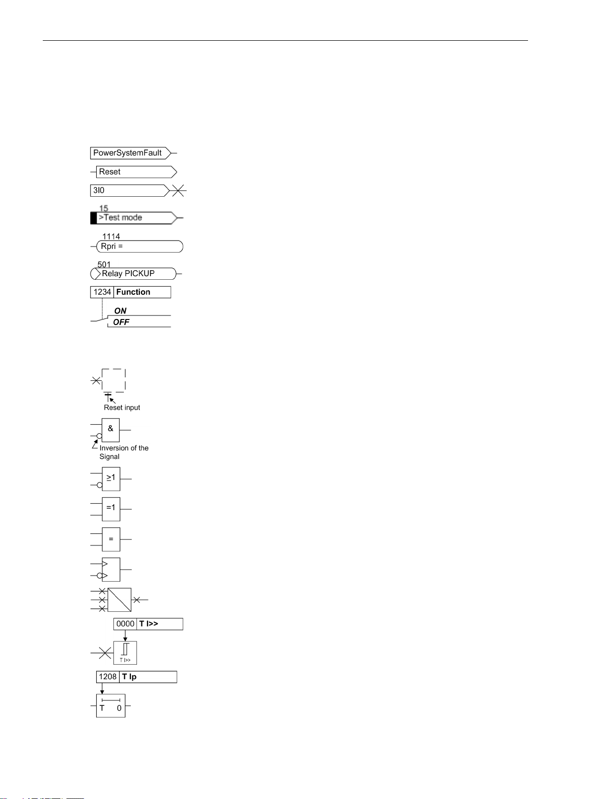
The following symbols are used in drawings:
Device-internal logical input signal
Device-internal logical output signal
Internal input signal of an analog quantity
External binary input signal with number (binary input,
input indication)
External binary output signal with number
(example of a value indication)
External binary output signal with number (device indication) used as
input signal
Example of a parameter switch designated FUNCTION with address
1234 and the possible settings ON and OFF
Besides these, graphical symbols are used in accordance with IEC 60617-12 and IEC 60617-13 or similar.
Some of the most frequently used are listed below:
Analog input variable
AND-gate operation of input values
OR-gate operation of input values
Exclusive OR gate (antivalence): output is active, if only one of the
inputs is active
Coincidence gate: output is active, if both inputs are active or inactive
at the same time
Dynamic inputs (edge-triggered) above with positive, below with
negative edge
Formation of one analog output signal from a number of analog input
signals
Limit stage with setting address and parameter designator (name)
Timer (pickup delay T, example adjustable) with setting address and
parameter designator (name)
6 SIPROTEC 4, 7VK61, Manual
C53000-G1176-C159-5, Edition 05.2018

Timer (dropout delay T, example non-adjustable)
Dynamic triggered pulse timer T (monoflop)
Static memory (SR flipflop) with setting input (S), resetting input (R),
output (Q) and inverted output (Q), setting input dominant
Static memory (RS-flipflop) with setting input (S), resetting input (R),
output (Q) and inverted output (Q), resetting input dominant
Preface
SIPROTEC 4, 7VK61, Manual 7
C53000-G1176-C159-5, Edition 05.2018

8 SIPROTEC 4, 7VK61, Manual
C53000-G1176-C159-5, Edition 05.2018

Open Source Software
The product contains, among other things, Open Source Software developed by third parties. The Open
Source Software used in the product and the license agreements concerning this software can be found in the
Readme_OSS. These Open Source Software files are protected by copyright. Your compliance with those
license conditions will entitle you to use the Open Source Software as foreseen in the relevant license. In the
event of conflicts between Siemens license conditions and the Open Source Software license conditions, the
Open Source Software conditions shall prevail with respect to the Open Source Software portions of the software. The Open Source Software is licensed royalty-free. Insofar as the applicable Open Source Software
License Conditions provide for it you can order the source code of the Open Source Software from your
Siemens sales contact - against payment of the shipping and handling charges - for a period of at least 3 years
since purchase of the Product. We are liable for the Product including the Open Source Software contained in
it pursuant to the license conditions applicable to the Product. Any liability for the Open Source Software
beyond the program flow intended for the Product is explicitly excluded. Furthermore any liability for defects
resulting from modifications to the Open Source Software by you or third parties is excluded. We do not
provide any technical support for the Product if it has been modified.
SIPROTEC 4, 7VK61, Manual
C53000-G1176-C159-5, Edition 05.2018
9

10 SIPROTEC 4, 7VK61, Manual
C53000-G1176-C159-5, Edition 05.2018

Table of Contents
Preface..........................................................................................................................................................3
Open Source Software..................................................................................................................................9
1 Introduction................................................................................................................................................17
1.1 Overall Operation..............................................................................................................18
1.2 Application Scope............................................................................................................. 20
1.3 Characteristics.................................................................................................................. 22
2 Functions.................................................................................................................................................... 25
2.1 General ............................................................................................................................26
2.1.1 Functional Scope......................................................................................................... 26
2.1.1.1 Configuration of the Scope of Functions ................................................................ 26
2.1.1.2 Setting Notes......................................................................................................... 26
2.1.1.3 Settings................................................................................................................. 27
2.1.2 Device......................................................................................................................... 28
2.1.2.1 Trip-Dependent Indications.................................................................................... 28
2.1.2.2 Setting Notes......................................................................................................... 29
2.1.2.3 Settings................................................................................................................. 30
2.1.2.4 Information List..................................................................................................... 30
2.1.3 Power System Data 1...................................................................................................31
2.1.3.1 Setting Notes......................................................................................................... 32
2.1.3.2 Settings................................................................................................................. 35
2.1.4 Change Group............................................................................................................. 36
2.1.4.1 Purpose of the Setting Groups................................................................................ 36
2.1.4.2 Setting Notes......................................................................................................... 37
2.1.4.3 Settings................................................................................................................. 37
2.1.4.4 Information List..................................................................................................... 37
2.1.5 Power System Data 2...................................................................................................37
2.1.5.1 Setting Notes......................................................................................................... 37
2.1.5.2 Settings................................................................................................................. 39
2.1.5.3 Information List..................................................................................................... 40
2.1.6 Oscillographic Fault Records........................................................................................ 41
2.1.6.1 Functional Description........................................................................................... 41
2.1.6.2 Setting Notes......................................................................................................... 41
2.1.6.3 Settings................................................................................................................. 42
2.1.6.4 Information List..................................................................................................... 42
2.1.7 Ethernet EN100-Module.............................................................................................. 42
2.1.7.1 Functional Description........................................................................................... 42
2.1.7.2 Setting Notes......................................................................................................... 42
2.1.7.3 Information List..................................................................................................... 43
2.2 Automatic reclosure function (optional)............................................................................ 44
2.2.1 Functional Description.................................................................................................44
2.2.2 Setting Notes...............................................................................................................58
2.2.3 Settings.......................................................................................................................64
SIPROTEC 4, 7VK61, Manual 11
C53000-G1176-C159-5, Edition 05.2018

Table of Contents
2.2.4 Information List...........................................................................................................66
2.3 Overcurrent protection (optional)......................................................................................69
2.3.1 General....................................................................................................................... 69
2.3.2 Functional Description.................................................................................................69
2.3.3 Setting Notes...............................................................................................................75
2.3.4 Settings.......................................................................................................................80
2.3.5 Information List...........................................................................................................81
2.4 Synchronism and voltage check (optional).........................................................................83
2.4.1 Functional Description.................................................................................................83
2.4.2 Setting Notes...............................................................................................................89
2.4.3 Settings.......................................................................................................................94
2.4.4 Information List...........................................................................................................95
2.5 Under and over-voltage protection (optional).................................................................... 97
2.5.1 Overvoltage Protection................................................................................................ 97
2.5.2 Undervoltage protection............................................................................................102
2.5.3 Setting Notes.............................................................................................................107
2.5.4 Settings.....................................................................................................................110
2.5.5 Information List.........................................................................................................112
2.6 Circuit breaker failure protection (optional)..................................................................... 115
2.6.1 Functional Description...............................................................................................115
2.6.2 Setting Notes.............................................................................................................125
2.6.3 Settings.....................................................................................................................128
2.6.4 Information List.........................................................................................................129
2.7 Monitoring Functions......................................................................................................131
2.7.1 Measurement Supervision......................................................................................... 131
2.7.1.1 Hardware Monitoring...........................................................................................131
2.7.1.2 Software Monitoring............................................................................................ 133
2.7.1.3 Monitoring External Transformer Circuits..............................................................133
2.7.1.4 Monitoring the Phase Angle of the Positive Sequence Power.................................138
2.7.1.5 Malfunction Reaction........................................................................................... 140
2.7.1.6 Setting Notes....................................................................................................... 141
2.7.1.7 Settings............................................................................................................... 143
2.7.1.8 Information List................................................................................................... 144
2.7.2 Trip circuit supervision...............................................................................................144
2.7.2.1 Functional Description......................................................................................... 144
2.7.2.2 Setting Notes....................................................................................................... 147
2.7.2.3 Settings............................................................................................................... 147
2.7.2.4 Information List................................................................................................... 147
2.8 Function Control and Circuit Breaker Test ....................................................................... 149
2.8.1 Function Control........................................................................................................149
2.8.1.1 Closure Detection.................................................................................................149
2.8.1.2 Detection of the Circuit Breaker Position............................................................... 151
2.8.1.3 Open Pole Detektor.............................................................................................. 153
2.8.1.4 Pickup Logic of the Entire Device.......................................................................... 155
2.8.1.5 Tripping Logic of the Entire Device....................................................................... 155
2.8.2 Circuit breaker trip test.............................................................................................. 158
2.8.2.1 Function Description............................................................................................ 159
2.8.2.2 Information List................................................................................................... 159
12 SIPROTEC 4, 7VK61, Manual
C53000-G1176-C159-5, Edition 05.2018

Table of Contents
2.9 Auxiliary Functions..........................................................................................................161
2.9.1 Processing of Messages............................................................................................. 161
2.9.1.1 Functional Description......................................................................................... 161
2.9.2 Statistics....................................................................................................................164
2.9.2.1 Functional Description......................................................................................... 164
2.9.2.2 Setting Notes....................................................................................................... 164
2.9.2.3 Information List................................................................................................... 164
2.9.3 Measurement............................................................................................................ 165
2.9.3.1 Functional Description......................................................................................... 165
2.9.3.2 Information List................................................................................................... 166
2.9.4 Energy.......................................................................................................................167
2.9.4.1 Energy Metering.................................................................................................. 167
2.9.4.2 Setting Notes....................................................................................................... 167
2.9.4.3 Information List................................................................................................... 167
2.10 Command Processing......................................................................................................169
2.10.1 Control Authorization................................................................................................ 169
2.10.1.1 Type of Commands.............................................................................................. 169
2.10.1.2 Sequence in the Command Path...........................................................................169
2.10.1.3 Interlocking......................................................................................................... 170
2.10.1.4 Information List................................................................................................... 173
2.10.2 Control Device...........................................................................................................173
2.10.2.1 Functional Description......................................................................................... 173
2.10.2.2 Information List................................................................................................... 174
2.10.3 Process Data..............................................................................................................174
2.10.3.1 Functional Description......................................................................................... 174
2.10.3.2 Information List................................................................................................... 175
2.10.4 Protocol.....................................................................................................................175
2.10.4.1 Information List................................................................................................... 175
3 Mounting and Commissioning................................................................................................................. 177
3.1 Mounting and Connections............................................................................................. 178
3.1.1 Configuration Information......................................................................................... 178
3.1.2 Hardware Modifications.............................................................................................182
3.1.2.1 General................................................................................................................182
3.1.2.2 Disassembly......................................................................................................... 183
3.1.2.3 Switching Elements on Printed Circuit Boards....................................................... 186
3.1.2.4 Interface Modules................................................................................................ 195
3.1.2.5 Reassembly..........................................................................................................199
3.1.3 Mounting.................................................................................................................. 199
3.1.3.1 Panel Flush Mounting...........................................................................................199
3.1.3.2 Rack and Cubicle Mounting.................................................................................. 200
3.1.3.3 Panel Mounting....................................................................................................202
3.2 Checking Connections.....................................................................................................203
3.2.1 Checking Data Connections of Serial Interfaces.......................................................... 203
3.2.2 Checking the System Connections............................................................................. 205
3.3 Commissioning............................................................................................................... 208
3.3.1 Test Mode/Transmission Block................................................................................... 209
3.3.2 Checking the Time Synchronisation Interface............................................................. 209
3.3.3 Test system interface.................................................................................................209
3.3.4 Checking the switching states of the binary Inputs/Outputs........................................211
3.3.5 Checking for Breaker Failure Protection......................................................................213
3.3.6 Current, Voltage, and Phase Rotation Testing............................................................. 215
SIPROTEC 4, 7VK61, Manual 13
C53000-G1176-C159-5, Edition 05.2018

Table of Contents
3.3.7 Directional Check with Load Current.......................................................................... 216
3.3.8 Polarity Check for the Voltage Input U4.......................................................................217
3.3.9
Polarity Check for the Current Input Ι4 ....................................................................... 219
3.3.10 Measuring the Operating Time of the Circuit Breaker..................................................219
3.3.11 Check of the Signal Transmission for Breaker Failure Protection and/or End Fault
Protection................................................................................................................. 220
3.3.12 Testing User-defined Functions..................................................................................220
3.3.13 Trip and Close Test with the Circuit Breaker................................................................220
3.3.14 Switching Test of the Configured Operating Equipment............................................. 221
3.3.15 Triggering Oscillographic Recording for Test...............................................................221
3.4 Final Preparation of the Device........................................................................................223
4 Technical Data.......................................................................................................................................... 225
4.1 General...........................................................................................................................226
4.1.1 Analogue Inputs and Outputs.................................................................................... 226
4.1.2 Auxiliary Voltage....................................................................................................... 226
4.1.3 Binary Inputs and Outputs......................................................................................... 227
4.1.4 Communication Interfaces.........................................................................................228
4.1.5 Electrical Tests...........................................................................................................231
4.1.6 Mechanical Tests....................................................................................................... 233
4.1.7 Climatic Stress Tests.................................................................................................. 233
4.1.8 Deployment Conditions............................................................................................. 234
4.1.9 Construction..............................................................................................................234
4.2 Automatic reclosure function (optional).......................................................................... 235
4.3 Overcurrent protection (optional)....................................................................................236
4.4 Synchronism and voltage check (optional).......................................................................243
4.5 Under and over-voltage protection (optional).................................................................. 244
4.6 Circuit breaker failure protection (optional)..................................................................... 247
4.7 Monitoring Functions......................................................................................................248
4.8 User-defined Functions (CFC).......................................................................................... 250
4.9 Auxiliary Functions..........................................................................................................254
4.10 Dimensions.....................................................................................................................256
4.10.1
4.10.2
4.10.3
4.10.4
Panel Flush Mounting or Cubicle Mounting (housing size 1/3)..................................... 256
Panel Flush Mounting or Cubicle Mounting (housing size 1/2) .....................................257
Panel surface mounting (housing size 1/3).................................................................. 258
Panel surface mounting (housing size 1/2).................................................................. 258
A Ordering Information and Accessories.....................................................................................................259
A.1 Ordering information MLFB ordering code.......................................................................260
A.2 Accessories.....................................................................................................................262
B Terminal Assignments..............................................................................................................................265
B.1 Housing for Panel Flush or Cubicle Mounting .................................................................. 266
B.2 Housing for Panel Surface Mounting................................................................................268
C Connection Examples............................................................................................................................... 271
C.1 Current Transformer Connection Examples......................................................................272
14 SIPROTEC 4, 7VK61, Manual
C53000-G1176-C159-5, Edition 05.2018

Table of Contents
C.2 Voltage Transformer Connection Examples......................................................................273
D Default Settings and Protocol-dependent Functions............................................................................... 277
D.1 LEDs............................................................................................................................... 278
D.2 Binary input default settings............................................................................................279
D.3 Binary output default settings......................................................................................... 280
D.4 Function key default settings...........................................................................................281
D.5 Default Display................................................................................................................282
D.6 Pre-defined CFC Charts....................................................................................................283
D.7 Protocol-dependent Functions.........................................................................................284
E Functions, Settings, Information..............................................................................................................285
E.1 Functional Scope............................................................................................................ 286
E.2 Settings.......................................................................................................................... 287
E.3 Information List ..............................................................................................................308
E.4 Group Indications............................................................................................................342
E.5 Measured Values.............................................................................................................343
Literature.................................................................................................................................................. 345
Glossary.................................................................................................................................................... 347
Index.........................................................................................................................................................357
SIPROTEC 4, 7VK61, Manual 15
C53000-G1176-C159-5, Edition 05.2018

16 SIPROTEC 4, 7VK61, Manual
C53000-G1176-C159-5, Edition 05.2018

1
Introduction
The SIPROTEC 4 device 7VK61 is introduced in this chapter. The device is presented in its application, characteristics, and functional scope.
1.1 Overall Operation 18
1.2 Application Scope 20
1.3 Characteristics 22
SIPROTEC 4, 7VK61, Manual 17
C53000-G1176-C159-5, Edition 05.2018
Introduction
1.1 Overall Operation
1.1
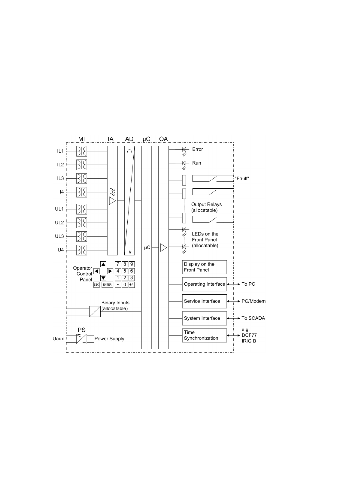
Analog Inputs
Overall Operation
The digital breaker management relay SIPROTEC 4 7VK61 is equipped with a powerful microprocessor system.
All tasks are processed fully digitally, from the acquisition of measured values up to sending commands to the
circuit breakers. Figure 1-1 shows the basic structure of the 7VK61.
The measuring inputs (MI) transform the currents and voltages from the instrument transformers and match
them to the internal signal levels for processing in the device. The device has 4 current inputs and 4 voltage
inputs. Three current inputs are provided for measuring the phase currents, a further measuring input (Ι4) can
be configured to detect the earth current (CT starpoint) or a separate earth current transformer. The analog
input quantities are passed on to the input amplifiers (IA).
[hw-struktur-7vk61-oz-251102, 1, en_GB]
Figure 1-1
A voltage measuring input is provided for each phase-earth voltage. A further voltage input (U4) may be
selected to measure either the displacement voltage, or the additional voltage for synchronism and voltage
check or for any other voltage UX (for overvoltage protection). The analogue values are transferred to the IA
input amplifier group.
The input amplifier group IA provides high-resistance termination for the analog input quantities. It consists of
filters that are optimized for measured value processing with regard to bandwidth and processing speed.
The AD analog-to-digital converter group contains analog/digital converters and memory chips for data
transfer to the microcomputer system.
18 SIPROTEC 4, 7VK61, Manual
Hardware-Struktur des Breaker Management Devicees 7VK61
C53000-G1176-C159-5, Edition 05.2018

Microcomputer System
Apart from processing the measured values, the microcomputer system µC also executes the actual protection
and control functions. This especially includes:
Filtering and conditioning of the measured signals
•
Continuous monitoring of the measured quantities
•
Monitoring of the pickup conditions for the individual protection functions
•
Monitoring of limit values and time sequences
•
Control of signals for logical functions
•
Reaching trip and close command decisions
•
Recording of messages, fault data and fault values for analysis
•
Administration of the operating system and its functions, e.g. data storage, realtime clock, communica-
•
tion, interfaces, etc.
The information is provided via output amplifier OA.
Binary Inputs and Outputs
Binary inputs from and outputs to the computer system are routed via the I/O modules (inputs and outputs).
The computer system obtains information from the system (e.g remote resetting) or from the external equipment (e.g. blocking commands). Outputs are commands that are issued to the switching devices and
messages for remote signaling of important events and states.
Introduction
1.1 Overall Operation
Front Elements
LEDs and an LC display provide information on the function of the device and indicate events, states and
measured values.
Integrated control and numeric keys in conjunction with the LCD facilitate local communication with the
device. Thus, all information of the device, e.g. configuration and setting parameters, operating and fault
messages, and measured values can be retrieved or changed (see also chapter 2 and SIPROTEC 4 System
Description).
Serial Interfaces
The serial
the DIGSI operating program. This allows all device functions to be handled conveniently.
The serial service interface can also be used for communication with a personal computer using DIGSI. This
port is especially well suited for a permanent connection of the devices to the PC or for operation via a
modem.
All device data can be transmitted to a control center through the serial
and physical arrangements are available for this interface to suit a particular application.
An additional interface is provided for
tion sources.
Further communication protocols can be realized via additional interface modules.
Power Supply
The functional units described are powered by a power supply, PS, with adequate power in the different
voltage levels. Brief supply voltage dips which may occur during short circuits in the auxiliary voltage supply of
the substation, are usually bridged by a capacitor (see also Technical Data, Section 4.1 General).
operator interface in the front cover enables communication with a personal computer when using
system interface. Various protocols
time synchronization of the internal clock through external synchroniza-
SIPROTEC 4, 7VK61, Manual 19
C53000-G1176-C159-5, Edition 05.2018

Introduction
1.2 Application Scope
1.2
Protective Functions
Application Scope
The 7VK61 breaker management relay is a multi-purpose starting and control device for automatic and
manual closing of circuit breakers in electrical networks of all voltage levels.
The automatic reclose function may be used on overhead lines for single-pole, three-pole or single- and threepole automatic reclosure as well as multi-shot automatic reclosure. The adaptive dead times can be set individually for single-pole, three-pole auto-reclosure and for additional (up to 8) reclose cycles.
Before reclosure after three-pole tripping, the validity of the reclosure can be checked by synchronism check
by the device (can be ordered optionally). Alternatively, the de-energization of the line or of the busbar can be
checked. If desired, asynchronous energization is also possible. In this case, the device calculates the moment
of the energization command so that the two voltages at busbar and feeder are in phase the instant the
circuit-breaker poles make contact.
The circuit breaker must be suitable for auto-reclosing. For single-pole auto-reclosure the poles must be individually controllable. The device considers whether the circuit breaker is ready for a trip and close cycle and its
position - provided this information is supplied by the circuit breaker. The breaker recovery time can be monitored. During single-pole auto-reclosure the relay can either process the parallel connection or the series
connection or both connections of the auxiliary contacts at the circuit breaker poles. The relay is furthermore
capable of processing the auxiliary contact of each pole. But generally the relay can operate without such
information from the circuit breaker.
7VK61 can work together with static and digital protection equipment requiring only pickup and trip operations from them. For single-pole auto-reclosure the trip signals must either be distinguished as to whether
they are single-pole or three pole or they must be transmitted to the relay for each pole separately. In the
event of three-pole auto-reclosure alone a general trip signal is sufficient.
The 7VK61 features the following basic functions:
Auto-Reclose function
•
Synchronism and Voltage Check
•
Circuit Breaker Failure Protection
•
Under/Overvoltage Protection
•
Backup overcurrent
•
Control Functions
The device is equipped with control functions which operate, close and open, switchgear devices via control
keys, the system interface, binary inputs and a PC with DIGSI software. The status of the primary equipment
can be transmitted to the device via auxiliary contacts connected to binary inputs. The present status (or position) of the primary equipment can be displayed on the device, and used for interlocking or plausibility monitoring. The number of the devices to be switched is limited by the binary inputs and outputs available in the
device or the binary inputs and outputs allocated for the switch position feedbacks. Depending on the mode
of operation, one binary input (single point indication) or two binary inputs (double point indication) can be
used. The capability of switching primary equipment can be restricted by appropriate settings for the
switching authority (remote or local), and by the operating mode (interlocked/non-interlocked, with or
without password validation). Interlocking conditions for switching (e.g. switchgear interlocking) can be
established using the integrated userdefined logic.
Indications and Measured Values; Fault Recording
The operational indications provide information about conditions in the power system and the device. Measurement quantities and values that are calculated can be displayed locally and communicated via the serial
interfaces.
Device messages can be assigned to a number of LEDs on the front panel (programmable), can be externally
processed via output contacts (programmable), linked with user-definable logic functions and/or issued via
serial interfaces (see Communication below).
20 SIPROTEC 4, 7VK61, Manual
C53000-G1176-C159-5, Edition 05.2018

During a fault (system fault) important events and changes in conditions are saved in fault logs. Instantaneous
fault values are also saved in the device and may be analyzed at a later time.
Communication
Serial interfaces are available for the communication with operating, control and memory systems.
A 9-pin DSUB socket on the front panel is used for local communication with a personal computer. By means
of the SIPROTEC 4 operating software DIGSI, all operational and evaluation tasks can be executed via this
ator interface, such as specifying and modifying configuration parameters and settings, configuring userspecific logic functions, retrieving operational and fault messages and measured values, reading out and
displaying fault recordings, inquiring device conditions and measured values, issuing control commands.
To establish an extensive communication with other digital operating, control and memory components the
device may be provided with further interfaces depending on the order variant.
The
modem. For this reason, remote operation is possible via PC and the DIGSI operating software, e.g. to operate
several devices via a central PC.
The
operated through the RS232, the RS485 or the FO port. Several standardized protocols are available for data
transmission. An EN 100 module allows integrating the devices into 100 MBit Ethernet communication
networks of the process control and automation system, using IEC 61850 protocols. In parallel to the link with
the process control and automation system, this interface can also handle DIGSI communication and interrelay communication using GOOSE messaging.
Another interface is provided for the
sources (IRIG-B or DCF77).
Introduction
1.2 Application Scope
oper-
service interface can be operated via the RS232 or RS485 interface and also allows communication via
system interface is used for central communication between the device and a control center. It can be
time synchronization of the internal clock via external synchronization
SIPROTEC 4, 7VK61, Manual 21
C53000-G1176-C159-5, Edition 05.2018

Introduction
1.3 Characteristics
1.3
General Features
Automatic reclosure function (optional)
Characteristics
Powerful 32-bit microprocessor system
•
Complete digital processing of measured values and control, from the sampling and digitizing of the
•
measure quantities up to the closing and tripping commands to the circuit breakers
Complete galvanic separation and interference immunity of the internal processing circuits from the
•
measurement, control, and power supply circuits by analog input transducers, binary inputs and outputs
and the DC/DC or AC/DC converters
Simple device operation using the integrated operator panel or a connected personal computer with
•
operator guidance
Storage of fault indications and instantaneous values for fault recording
•
For reclosure after 1-pole, 3-pole or 1-pole and 3-pole tripping
•
Single or multiple reclosure (up to eight reclosure attempts)
•
With separate action time setting for the first 4 reclose attempts, optionally without action times
•
With separate dead times after 1-pole and 3-pole tripping, separate for the first four reclosure attempts
•
Controlled optionally by protection pickup with separate dead times after 1-pole , 2-pole or 3-pole pickup
•
Optionally with adaptive dead time, reduced dead time and dead line check
•
Synchronism and voltage check (optional)
Verification of the synchronous conditions before reclosing after three-pole tripping
•
Fast measurement of the voltage difference U
•
difference f
Alternatively, check of the de-energized state before reclosing
•
Closing at asynchronous system conditions with consideration of the CB closing time to achieve system
•
re-connection when voltages are in phase
Settable minimum and maximum voltage
•
Verification of the synchronous conditions or de-energized state before manual closing of the circuit
•
breaker is possible with separate setting thresholds and states
Phase angle compensation for voltage measurement behind a transformer
•
Measuring voltages optionally phase-phase or phase-earth
•
Time Overcurrent Protection (optional, available with breaker failure protection)
Two definite time stages (DT) and one inverse time stage (IDMT), each for phase currents and earth
•
current
For inverse-time overcurrent protection select from various characteristics based on several standards
•
Blocking capability e.g. for reverse interlocking with any stage
•
Instantaneous tripping by any stage when switching onto a fault
•
Additional stage, e.g. stub protection, for fast tripping of faults between the current transformer and line
•
isolator (when the isolator switching status feedback is available); particularly well suited to substations
with 11/2 circuit breaker arrangements.
diff
, the phase angle difference φ
diff
and the frequency
diff
22 SIPROTEC 4, 7VK61, Manual
C53000-G1176-C159-5, Edition 05.2018

Circuit Breaker Failure Protection (optional)
With definite time current stages for monitoring the current flow through every pole of the circuit
•
breaker
Separate pickup thresholds for phase and earth currents
•
Independent timers for single-pole and three-pole tripping
•
Start by trip command of every internal protection function
•
Start by external trip functions possible
•
Single-stage or two-stage
•
Short dropout and overshoot times
•
Voltage Protection (optional)
Overvoltage and undervoltage detection with different stages
•
Two overvoltage stages for the phase-earth voltages
•
Two overvoltage stages for the phase-phase voltages
•
Two overvoltage stages for the positive sequence voltage
•
Two overvoltage stages for the negative sequence voltage
•
Two overvoltage stages for the zero sequence voltage or any other single-phase voltage
•
Settable dropout to pickup ratios
•
Two undervoltage stages for the phase-earth voltages
•
Two undervoltage stages for the phase-phase voltages
•
Two undervoltage stages for the positive sequence voltage
•
Settable current criterion for undervoltage protection functions
•
Introduction
1.3 Characteristics
User-defined Logic Functions (CFC)
Freely programmable combination of internal and external signals for the implementation of user-
•
defined logic functions
All typical logic functions
•
Time delays and limit value inquiries
•
Command Processing
Switchgear can be switched on and off manually via local control keys, the programmable function keys
•
on the front panel, via the system interface (e.g. by SICAM or LSA), or via the operator interface (using a
personal computer and the operating software DIGSI)
Feedback on switching states via the circuit breaker auxiliary contacts (for commands with feedback)
•
Monitoring of the circuit breaker position and of the interlocking conditions for switching operations.
•
Monitoring Functions
Availability of the device is greatly increased because of self-monitoring of the internal measurement
•
circuits, power supply, hardware and software
Monitoring of the current and voltage transformer secondary circuits by means of summation and
•
symmetry checks
Trip circuit supervision
•
Checking for the measured direction and the phase sequence.
•
SIPROTEC 4, 7VK61, Manual 23
C53000-G1176-C159-5, Edition 05.2018

Introduction
1.3 Characteristics
Additional Functions
Battery buffered real time clock, which may be synchronised via a synchronisation signal (e.g. DCF77,
•
IRIGB via satellite receiver), binary input or system interface
Continuous calculation and display of measured quantities on the front display.
•
Fault event memory (trip log) for the last eight network faults (faults in the power system), with real time
•
stamps
Fault recording and data transfer for fault recording for a maximum time range of approx. 15 seconds
•
Switching statistics: Counting of the trip and close commands issued by the device, as well as recording
•
of the fault current data and accumulation of the interrupted fault currents
Communication with central control and memory components possible via serial interfaces (depending
•
on the options ordered), optionally via RS232, RS485, modem connection or fibre optic cable
Commissioning aids such as connection and direction checks as well as circuit breaker test functions
•
24 SIPROTEC 4, 7VK61, Manual
C53000-G1176-C159-5, Edition 05.2018

2
Functions
This chapter describes the individual functions of the SIPROTEC 4 device 7VK61. It shows the setting possibilities for each function in maximum configuration. Guidelines for establishing setting values and, where
required, formulae are given.
Based on the following information, it can also be determined which of the provided functions should be
used.
2.1 General 26
2.2 Automatic reclosure function (optional) 44
2.3 Overcurrent protection (optional) 69
2.4 Synchronism and voltage check (optional) 83
2.5 Under and over-voltage protection (optional) 97
2.6 Circuit breaker failure protection (optional) 115
2.7 Monitoring Functions 131
2.8 Function Control and Circuit Breaker Test 149
2.9 Auxiliary Functions 161
2.10 Command Processing 169
SIPROTEC 4, 7VK61, Manual 25
C53000-G1176-C159-5, Edition 05.2018

i
i
Functions
2.1 General
2.1
2.1.1
2.1.1.1
General
A few seconds after the device is switched on, the initial display appears in the LCD. A selection of measured
values is displayed.
Configuration of the device functions are made via the DIGSI software from your PC. The procedure is
described in detail in the SIPROTEC 4 System Description. Entry of password No. 7 (for setting modification) is
required to modify configuration settings. Without the password, the settings may be read, but may not be
modified and transferred to the device.
The function parameters, i.e. settings of function options, threshold values, etc., can be entered via the
keypad and display on the front of the device, or by means of a personal computer connected to the front or
service interface of the device utilizing the DIGSI software package. The level 5 password (individual parameters) is required.
Functional Scope
Configuration of the Scope of Functions
The 7VK61 relay contains a series of protective and additional functions. The hardware and firmware provided
is designed for this scope of functions. In addition, the command functions can be matched to the system
conditions. Individual functions can be activated or deactivated during the configuration procedure. The interaction of functions may also be modified e.g., the reclosing function can be implemented with or without
synchronization. If a function is not required, it can be deactivated during configuration.
The available protection functions and additional functions can be configured as Enabled or Disabled. For
some functions, a choice between several options is possible which are described below.
Functions configured as Disabled are not processed by the 7VK61. There are no indications, and corresponding settings (functions, limit values) are not displayed during setting.
NOTE
The functions and default settings available depend on the device version ordered.
2.1.1.2
Configuring the functional scope
Special Cases
Setting Notes
The scope of functions with the available options is set in the Functional Scope dialog box to match plant
requirements.
Most settings are self-explanatory.
If use of the setting group changeover function is desired, address 103 Grp Chge OPTION should be set to
Enabled. In this case, up to four different groups of settings may be changed (see also Section 2.1.4 Change
Group), quickly and easily during device operation. With the setting Disabled only one parameter group is
available.
Address 106 VT CONNECTION determines how the voltage transformers are connected. VT CONNECTION =
3phase implies that the three phase voltages are connected in wye connection. VT CONNECTION = 1phase
is selected, if the device is connected to only one voltage transformer. In this case, the voltage connected to
voltage input U4 is always interpreted as the voltage UU
transformer is then invariably set to Usy2 transf. and excludes other setting options. The parameter
212 Usy2 connection is then hidden. The setting VT CONNECTION = NO hides all voltage-relevant functions and parameters.
Parameter 107 CT CONNECTION is set to configure the current transformer connection. If the default setting
CT CONNECTION = YES is active, all current-induced functions (current criterion of voltage protection, line
status detection, measurements of currents and power, current-induced measured value monitoring) are
Besonderheiten are described below.
which is to be synchronized. Parameter 210 U4
sy2
26 SIPROTEC 4, 7VK61, Manual
C53000-G1176-C159-5, Edition 05.2018

i
i
Functions
2.1 General
operational. The setting CT CONNECTION = NO allows the device to be operated without any current transformer connection; all current-induced functions and parameters are then hidden.
Address 110 Trip mode is only valid for devices that can trip single-pole or three-pole. Set 1-/3pole to also
enable single-pole tripping, i.e. if you want to utilize single-pole or single-pole/three-pole automatic reclosure.
This requires that an internal automatic reclosure function exists or that an external reclosing device is used.
Furthermore, the circuit breaker must be capable of single-pole tripping.
All functions are set to Disabled by default. This has no effect on the presetting of LEDs, binary inputs and
binary outputs.
NOTE
If you have changed address 110, save your changes first via OK and reopen the dialog box since the other
setting options depend on the selection in address 110.
If the device features an automatic reclosing function, address 133 and 134 are of importance. Automatic
reclosure is only permitted for overhead lines. It must not be used in any other case. If the protected object
consists of a combination of overhead lines and other equipment (e.g. overhead line in unit with a transformer or overhead line/cable), reclosure is only permissible if it can be ensured that it can only take place in
the event of a fault on the overhead line. If no automatic reclosing function is desired for the feeder at which
7VK61operates, or if an external device is used for reclosure, set address 133 Auto Reclose to Disabled.
Otherwise set the number of desired reclosing attempts there. You can select 1 AR-cycle to 8 AR-cycles.
You can also set ADT(adaptive dead times); in this case the behavior of the automatic reclosure function is
determined by the cycles of the remote end. The number of cycles must however be configured at least in one
of the line ends which must have a reliable infeed. The other end — or other ends, if there are more than two
line ends — may operate with adaptive dead time. Section provides detailed information on this topic
2.2 Automatic reclosure function (optional) .
The AR control mode at address 134 allows a total of four options. On the one hand, it can be determined
whether the auto reclose cycles are carried out according to the fault type detected by the pickup of the
starting protection function(s) (only for three-pole tripping) or according to the type of trip command. On the
other hand, the automatic reclosure function can be operated with or without action time.
The setting Trip with T-action / Trip without T-action ... (default setting = Trip with Taction) is preferred if
different dead times (for every AR cycle) are possible after 1-pole tripping and after 3-pole tripping. The
protection function that issues the trip command determines the type of trip: 1-pole or 3-pole. The dead time
is controlled dependent on this.
The setting PICKUP. ... (With PICKUP ...) is only possible and visible, when only 3-pole tripping should occur,
i.e., only 3-pole tripping is configured (address 110 Trip mode = 3pole only, see above). In this case you
can set different dead times for the auto-reclose cycles following
the pickup situation of the protective functions at the instant the trip command disappears. This control mode
enables also the dead times to be made dependent on the type of fault in the case of three-pole reclosure
cycles. Tripping is always three-pole.
The setting ... and tact (with ... action time ) provides an action time for every reclose cycle. The action
time is started by a general pickup of all protection functions. If no trip command is present before the action
time expires, the corresponding reclosure cycle is not carried out. Section provides detailed information on
this topic 2.2 Automatic reclosure function (optional) . This setting is recommended for time-graded protection. If the protection function which is to operate with automatic reclosure, does not have a general pickup
signal for starting the action times, select Trip without T-action... (without action time).
For the trip circuit supervision set at address 140 Trip Cir. Sup. the number of trip circuits to be monitored: 1 trip circuit, 2 trip circuits or 3 trip circuits, unless you omit it Disabled).
1-polige or 1-/3-polige auto reclose cycles are provided for and possible. In this case,
1-, 2- and 3-phase. The decisive factor here is
2.1.1.3
Addr.
103 Grp Chge OPTION Disabled
SIPROTEC 4, 7VK61, Manual 27
C53000-G1176-C159-5, Edition 05.2018
Settings
Parameter Setting Options Default Setting Comments
Disabled Setting Group Change Option
Enabled

Functions
2.1 General
Addr. Parameter Setting Options Default Setting Comments
106 VT CONNECTION 3phase
1phase
NO
107 CT CONNECTION YES
NO
110 Trip mode 3pole only
1-/3pole
126 Back-Up O/C Disabled
TOC IEC
TOC ANSI
TOC IEC /w 3ST
133 Auto Reclose 1 AR-cycle
2 AR-cycles
3 AR-cycles
4 AR-cycles
5 AR-cycles
6 AR-cycles
7 AR-cycles
8 AR-cycles
ADT
Disabled
134 AR control mode Pickup w/ Tact
Pickup w/o Tact
Trip w/ Tact
Trip w/o Tact
135 Synchro-Check Disabled
Enabled
137 U/O VOLTAGE Disabled
Enabled
139 BREAKER FAILURE Disabled
Enabled
enabled w/ 3I0>
140 Trip Cir. Sup. Disabled
1 trip circuit
2 trip circuits
3 trip circuits
3phase Voltage transformer connection
YES Current transformer connection
3pole only Trip mode
Disabled Backup overcurrent
Disabled Auto-Reclose Function
Trip w/ Tact Auto-Reclose control mode
Disabled Synchronism and Voltage Check
Disabled Under / Overvoltage Protection
Disabled Breaker Failure Protection
Disabled Trip Circuit Supervision
2.1.2
2.1.2.1
Spontaneous Fault Messages
28 SIPROTEC 4, 7VK61, Manual
Device
The device requires some general information. This may be, for example, the type of indication to be issued in
the event a power system fault occurs.
Trip-Dependent Indications
After a fault, the essential fault data spontaneously appear on the device display. Under address 610
FltDisp.LED/LCD you can select whether the spontaneous fault indications are updated in every case of
fault (Target on PU) or only in faults with tripping (Target on TRIP).
C53000-G1176-C159-5, Edition 05.2018
For devices with graphic display, you can specify in address 615 Spont. FltDisp. whether a spontaneous
i
i
fault message appears automatically on the display (YES) or not (NO). For devices with text display such indications will appear anyway after a power system fault.
[logik-spondanmeld-display-081024, 1, en_GB]
Figure 2-1 Generation of spontaneous fault indications on the display
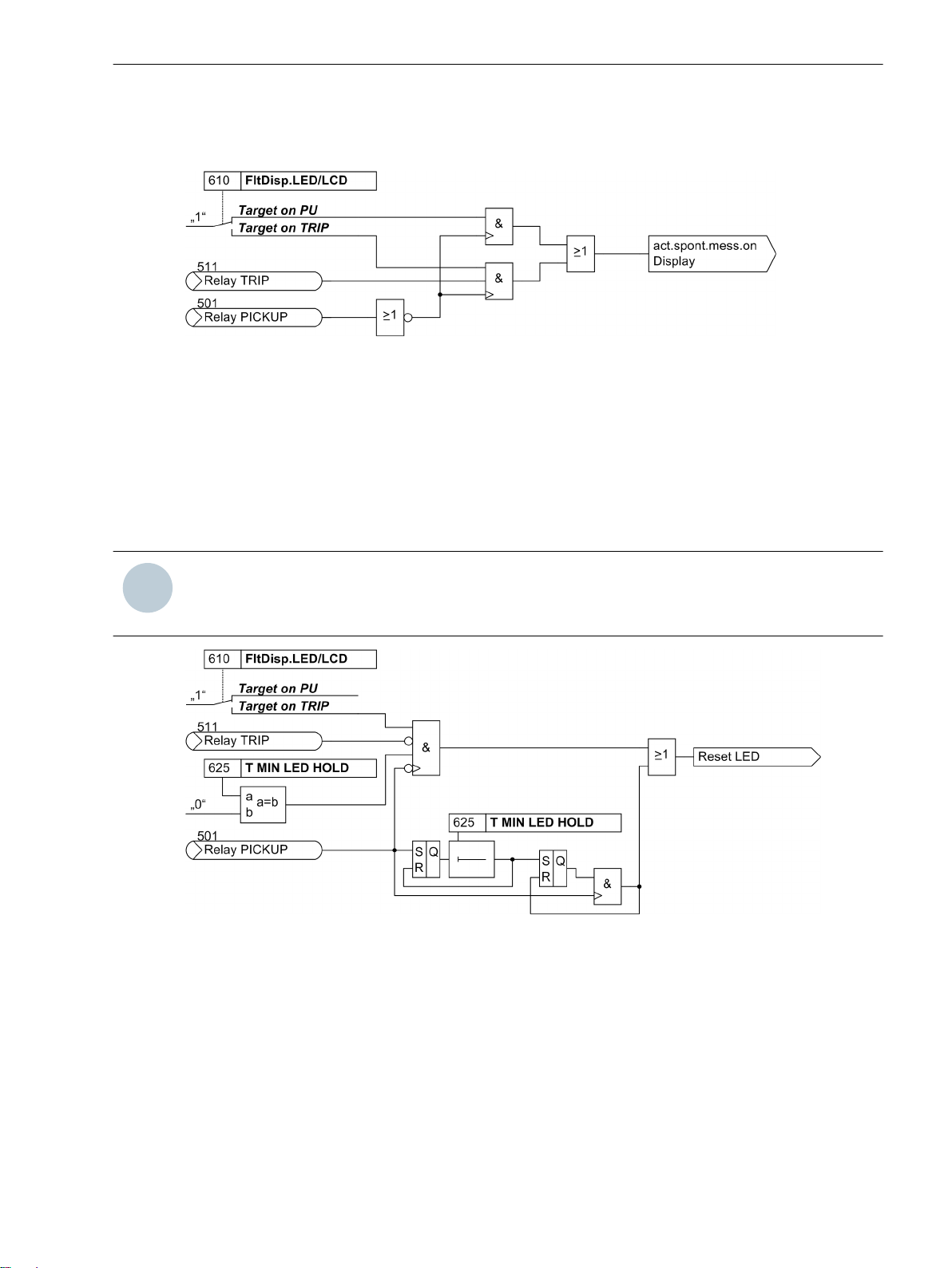
Reset of Stored LED / Relays
Pickup of a new protection function generally deletes all stored LED/relays so that only the information of the
latest fault is displayed at a time. The deletion of the stored LED and relays can be inhibited for a settable time
under address 625 T MIN LED HOLD. Any information occurring during this time are then combined with a
logical OR function.
Under address 610 FltDisp.LED/LCD also the information of the latest fault stored on LED and relays can
be deleted with the setting (Target on TRIP) unless this fault has lead to a trip command of the device.
Functions
2.1 General
NOTE
Setting the address 610 FltDisp.LED/LCD to (Target on TRIP) only makes sense if address 625 T
MIN LED HOLD is set to 0.
[logik-ruecksetz-gesp-led-081024, 1, en_GB]
Figure 2-2 Creation of the reset command for saved LED/relays
2.1.2.2
Fault Annunciations
Setting Notes
Pickup of a new protection function generally turns off any previously set displays, so that only the latest fault
is displayed at any one time. It can be selected whether the stored LED displays and the spontaneous indications on the display appear upon renewed pickup, or only after a renewed trip signal is issued. In order to
enter the desired type of display, select the submenu General Device Settings in the SETTINGS menu. At
address 610 FltDisp.LED/LCD the two alternatives Target on PU and Target on TRIP (“No trip - no
flag”) are offered.
SIPROTEC 4, 7VK61, Manual 29
C53000-G1176-C159-5, Edition 05.2018

Functions
2.1 General
After startup of the device featuring a 4-line display, default measured values are displayed. Use the arrow
keys on the device front to select different measured value views to be used as the so-called default display.
The start page of the default display, which will open after each startup of the device, can be selected via
parameter 640 Start image DD. The available representation types for the measured value are listed in the
Appendix.
2.1.2.3
Settings
Addresses which have an appended “A” can only be changed with DIGSI, under “Additional Settings”.
Addr. Parameter Setting Options Default Setting Comments
610 FltDisp.LED/LCD Target on PU
Target on PU Fault Display on LED / LCD
Target on TRIP
625A T MIN LED HOLD 0 .. 60 min 0 min Minimum hold time of latched
LEDs
640 Start image DD image 1
image 1 Start image Default Display
image 2
image 3
image 4
image 5
image 6
2.1.2.4
No.
Information List
Information Type of
Comments
Information
- Test mode IntSP Test mode
- DataStop IntSP Stop data transmission
- UnlockDT IntSP Unlock data transmission via BI
- Reset LED IntSP Reset LED
- SynchClock IntSP_Ev Clock Synchronization
- >Light on SP >Back Light on
- HWTestMod IntSP Hardware Test Mode
- Error FMS1 OUT Error FMS FO 1
- Error FMS2 OUT Error FMS FO 2
- Distur.CFC OUT Disturbance CFC
1 Not configured SP No Function configured
2 Non Existent SP Function Not Available
3 >Time Synch SP >Synchronize Internal Real Time Clock
5 >Reset LED SP >Reset LED
11 >Annunc. 1 SP >User defined annunciation 1
12 >Annunc. 2 SP >User defined annunciation 2
13 >Annunc. 3 SP >User defined annunciation 3
14 >Annunc. 4 SP >User defined annunciation 4
15 >Test mode SP >Test mode
16 >DataStop SP >Stop data transmission
51 Device OK OUT Device is Operational and Protecting
52 ProtActive IntSP At Least 1 Protection Funct. is Active
55 Reset Device OUT Reset Device
56 Initial Start OUT Initial Start of Device
67 Resume OUT Resume
30 SIPROTEC 4, 7VK61, Manual
C53000-G1176-C159-5, Edition 05.2018
 Loading...