


Preface
Open Source Software
Table of Contents
SIPROTEC 4
Multifunction Paralleling
Devices 7VE61 and 7VE63
V4.6
Manual
Introduction
Functions
Mounting and Commissioning
Technical Data
Ordering Information and Accessories
Terminal Assignments
Connection Examples
Default Settings and Protocol-dependent
Functions
Functions, Settings, Information
1
2
3
4
A
B
C
D
E
C53000-G1176-C163-3
Literature
Glossary
Index

i
i
NOTE
For your own safety, observe the warnings and safety instructions contained in this document, if available.
Disclaimer of Liability
This document has been subjected to rigorous technical
review before being published. It is revised at regular intervals, and any modifications and amendments are included
in the subsequent issues. The content of this document has
been compiled for information purposes only. Although
Siemens AG has made best efforts to keep the document as
precise and up-to-date as possible, Siemens AG shall not
assume any liability for defects and damage which result
through use of the information contained herein.
This content does not form part of a contract or of business
relations; nor does it change these. All obligations of
Siemens AG are stated in the relevant contractual agreements.
Siemens AG reserves the right to revise this document from
time to time.
Document version: C53000-G1176-C163-3.01
Edition: 10.2017
Version of the product described: V4.6
Copyright
Copyright © Siemens AG 2017. All rights reserved.
The disclosure, duplication, distribution and editing of this
document, or utilization and communication of the content
are not permitted, unless authorized in writing. All rights,
including rights created by patent grant or registration of a
utility model or a design, are reserved.
Registered Trademarks
SIPROTEC®, DIGSI®, SIGUARD®, SIMEAS®, and SICAM® are
registered trademarks of Siemens AG. Any unauthorized
use is illegal. All other designations in this document can
be trademarks whose use by third parties for their own
purposes can infringe the rights of the owner.
Preface
Purpose of this Manual
This manual describes the functions, operation, installation, and commissioning of devices 7VE61 and 7VE63.
In particular, one will find:
Information regarding the configuration of the scope of the device and a description of the device func-
•
tions and settings → Chapter 2;
Instructions for Installation and Commissioning → Chapter 3;
•
Compilation of the Technical Data → Chapter 4;
•
As well as a compilation of the most significant data for advanced users → Appendix A.
•
General information with regard to design, configuration, and operation of SIPROTEC 4 devices are set out in
the SIPROTEC 4 System Description /1/ SIPROTEC 4 System Manual.
Target Audience
Protection-system engineers, commissioning engineers, persons entrusted with the setting, testing and maintenance of selective protection, automation and control equipment, and operating personnel in electrical
installations and power plants.
Applicability of this Manual
This manual applies to: SIPROTEC 4 Multifunction Paralleling Devices 7VE61 and 7VE63; Firmware-Version
V4.6.
Indication of Conformity
Additional Standards IEEE Std C37.90 (see Chapter 4, “Technical Data”)
[ul-schutz-110602-kn, 1, --_--]
This product complies with the directive of the Council of the European Communities on the
approximation of the laws of the Member States relating to electromagnetic compatibility
(EMC Council Directive 2004/108/EC) and concerning electrical equipment for use within
specified voltage limits (Low-voltage directive 2006/95 EC).
This conformity is proved by tests conducted by Siemens AG in accordance with the Council
Directives in agreement with the generic standards EN61000-6-2 and EN 61000-6-4 for the
EMC directive, and with the standard EN 60255-27 for the low-voltage directive. The device
has been designed and produced for industrial use.
The product conforms with the international standard of the series IEC 60255 and the German
standard VDE 0435.
SIPROTEC 4, 7VE61 and 7VE63, Manual
C53000-G1176-C163-3, Edition 10.2017
3
!
!
!
Preface
Additional Support
For questions about the SIPROTEC 4 system, please contact your Siemens sales partner.
Our Customer Support Center provides a 24-hour service.
Phone: +49 (180) 524-8437
Fax: +49 (180) 524-2471
e-mail: support.ic@siemens.com
Training Courses
Inquiries regarding individual training courses should be addressed to our Training Center:
Siemens AG
Siemens Power Academy TD
Humboldtstraße 59
90459 Nürnberg
Germany
Phone: +49 (911) 433-7415
Fax: +49 (911) 433-7929
E-Mail: poweracademy@siemens.com
Internet: www.siemens.com/poweracademy
Notes on Safety
This document is not a complete index of all safety measures required for operation of the equipment (module
or device). However, it comprises important information that must be followed for personal safety, as well as
to avoid material damage. Information is highlighted and illustrated as follows according to the degree of
danger:
DANGER
GEFAHR bedeutet, dass Tod oder schwere Verletzungen eintreten werden, wenn die angegebenen
Maßnahmen nicht getroffen werden.
²
²
WARNING
WARNING means that death or severe injury may result if the measures specified are not taken.
²
Beachten Sie alle Hinweise, um Tod oder schwere Verletzungen zu vermeiden.
Danger indicates that death, severe personal injury or substantial material damage will result if proper
precautions are not taken.
Comply with all instructions, in order to avoid death or severe injuries.
CAUTION
CAUTION means that medium-severe or slight injuries can occur if the specified measures are not taken.
Comply with all instructions, in order to avoid moderate or minor injuries.
²
4 SIPROTEC 4, 7VE61 and 7VE63, Manual
C53000-G1176-C163-3, Edition 10.2017
i
i
NOTE
indicates information on the device, handling of the device, or the respective part of the instruction manual
which is important to be noted.
Typographic and Symbol Conventions
The following text formats are used when literal information from the device or to the device appear in the
text flow:
Parameter Names
Designators of configuration or function parameters which may appear word-for-word in the display of the
device or on the screen of a personal computer (with operation software DIGSI), are marked in bold letters in
monospace type style. The same applies to titles of menus.
1234A
Parameter addresses have the same character style as parameter names. Parameter addresses contain the
suffix A in the overview tables if the parameter can only be set in DIGSI via the option Display additional
settings.
Parameter Options
Possible settings of text parameters, which may appear word-for-word in the display of the device or on the
screen of a personal computer (with operation software DIGSI), are additionally written in italics. The same
applies to the options of the menus.
Indications
Designators for information, which may be output by the relay or required from other devices or from the
switch gear, are marked in a monospace type style in quotation marks.
Deviations may be permitted in drawings and tables when the type of designator can be obviously derived
from the illustration.
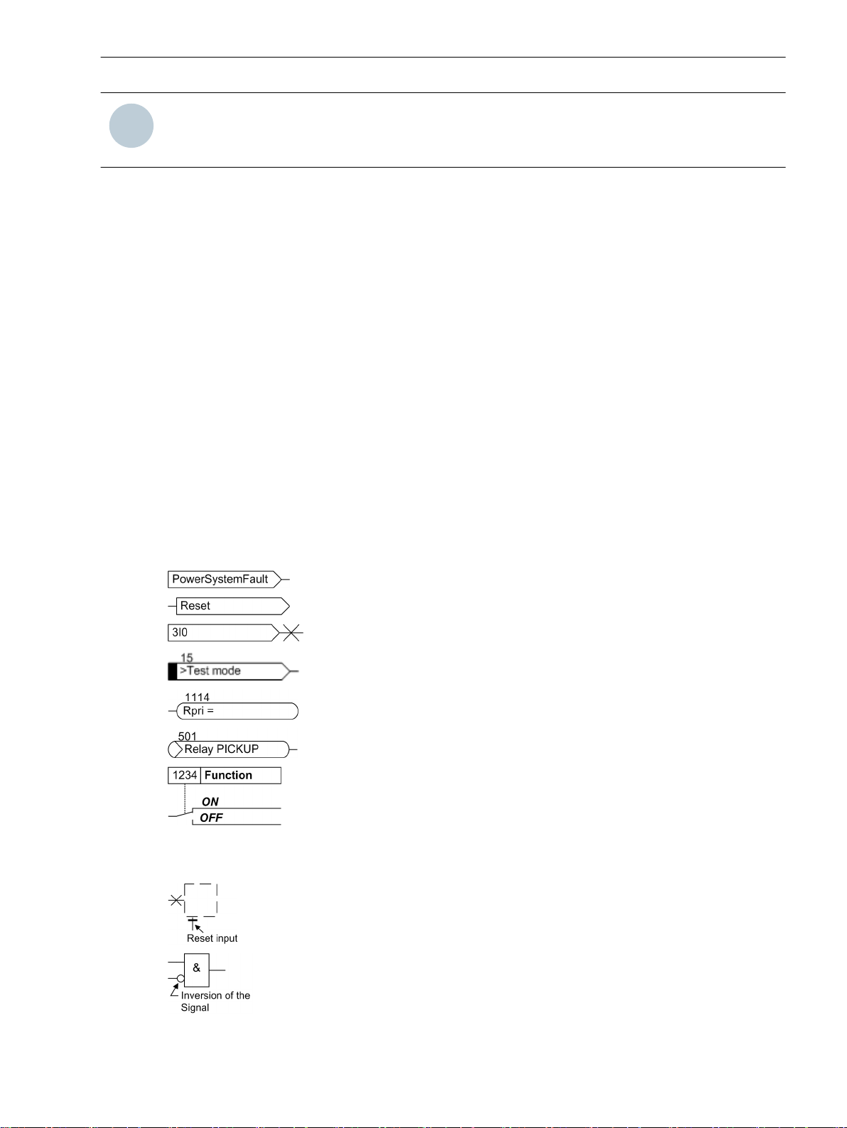
The following symbols are used in drawings:
Preface
Device-internal logical input signal
Device-internal logical output signal
Internal input signal of an analog quantity
External binary input signal with number (binary input,
input indication)
External binary output signal with number
(example of a value indication)
External binary output signal with number (device indication) used as
input signal
Example of a parameter switch designated FUNCTION with address
1234 and the possible settings Ein and Aus
Besides these, graphical symbols are used in accordance with IEC 60617-12 and IEC 60617-13 or similar.
Some of the most frequently used are listed below:
Analog input variable
AND-gate operation of input values
SIPROTEC 4, 7VE61 and 7VE63, Manual 5
C53000-G1176-C163-3, Edition 10.2017
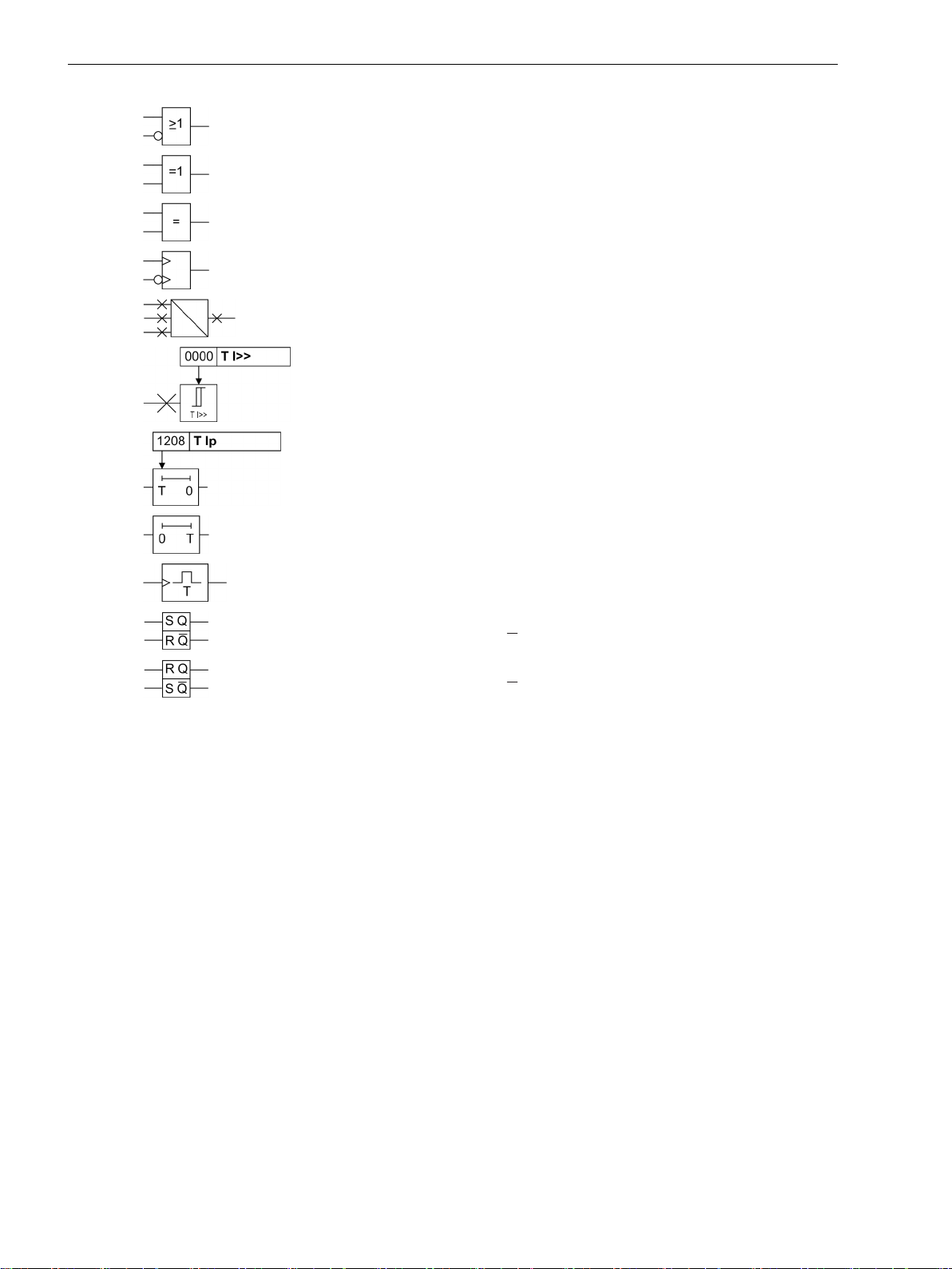
Preface
OR-gate operation of input values
Exclusive OR gate (antivalence): output is active, if only one of the
inputs is active
Coincidence gate: output is active, if both inputs are active or inactive
at the same time
Dynamic inputs (edge-triggered) above with positive, below with
negative edge
Formation of one analog output signal from a number of analog input
signals
Limit stage with setting address and parameter designator (name)
Timer (pickup delay T, example adjustable) with setting address and
parameter designator (name)
Timer (dropout delay T, example non-adjustable)
Dynamic triggered pulse timer T (monoflop)
Static memory (SR flipflop) with setting input (S), resetting input (R),
output (Q) and inverted output (Q), setting input dominant
Static memory (RS-flipflop) with setting input (S), resetting input (R),
output (Q) and inverted output (Q), resetting input dominant
6 SIPROTEC 4, 7VE61 and 7VE63, Manual
C53000-G1176-C163-3, Edition 10.2017

Open Source Software
The product contains, among other things, Open Source Software developed by third parties. The Open
Source Software used in the product and the license agreements concerning this software can be found in the
Readme_OSS. These Open Source Software files are protected by copyright. Your compliance with those
license conditions will entitle you to use the Open Source Software as foreseen in the relevant license. In the
event of conflicts between Siemens license conditions and the Open Source Software license conditions, the
Open Source Software conditions shall prevail with respect to the Open Source Software portions of the software. The Open Source Software is licensed royalty-free. Insofar as the applicable Open Source Software
License Conditions provide for it you can order the source code of the Open Source Software from your
Siemens sales contact - against payment of the shipping and handling charges - for a period of at least 3 years
since purchase of the Product. We are liable for the Product including the Open Source Software contained in
it pursuant to the license conditions applicable to the Product. Any liability for the Open Source Software
beyond the program flow intended for the Product is explicitly excluded. Furthermore any liability for defects
resulting from modifications to the Open Source Software by you or third parties is excluded. We do not
provide any technical support for the Product if it has been modified.
SIPROTEC 4, 7VE61 and 7VE63, Manual
C53000-G1176-C163-3, Edition 10.2017
7

8 SIPROTEC 4, 7VE61 and 7VE63, Manual
C53000-G1176-C163-3, Edition 10.2017

Table of Contents
Preface..........................................................................................................................................................3
Open Source Software..................................................................................................................................7
1 Introduction................................................................................................................................................15
1.1 Overall Operation..............................................................................................................16
1.2 Application Scope............................................................................................................. 18
1.3 Characteristics.................................................................................................................. 21
2 Functions.................................................................................................................................................... 25
2.1 General.............................................................................................................................26
2.1.1 Device......................................................................................................................... 26
2.1.1.1 Setting Notes......................................................................................................... 26
2.1.1.2 Settings................................................................................................................. 27
2.1.1.3 Information List..................................................................................................... 27
2.1.2 EN100-Modul 1........................................................................................................... 28
2.1.2.1 Functional Description........................................................................................... 28
2.1.2.2 Setting Notes......................................................................................................... 29
2.1.2.3 Information List..................................................................................................... 29
2.1.3 Functional Scope......................................................................................................... 29
2.1.3.1 Functional Description........................................................................................... 29
2.1.3.2 Setting Notes......................................................................................................... 29
2.1.3.3 Settings................................................................................................................. 30
2.1.4 Power System Data 1...................................................................................................32
2.1.4.1 Setting Notes......................................................................................................... 32
2.1.4.2 Settings................................................................................................................. 32
2.1.4.3 Information List..................................................................................................... 32
2.1.5 Change Group............................................................................................................. 33
2.1.5.1 Setting Notes......................................................................................................... 33
2.1.5.2 Settings................................................................................................................. 33
2.1.5.3 Information List..................................................................................................... 33
2.2 Paralleling Functions......................................................................................................... 35
2.2.1 Functional Description.................................................................................................35
2.2.1.1 Connection and definitions.................................................................................... 35
2.2.1.2 Synchronization via Transformers...........................................................................37
2.2.1.3
2.2.1.4 Monitoring Procedure............................................................................................ 40
2.2.1.5 Multiple Synchronizing Points................................................................................ 42
2.2.1.6 Operating Range/Measured values..........................................................................42
2.2.1.7 Synchrocheck.........................................................................................................43
2.2.1.8 Switching to Dead Line/Busbar............................................................................... 46
2.2.1.9 Switching Synchronous Systems.............................................................................49
2.2.1.10 Switching Asynchronous Systems...........................................................................50
2.2.1.11 Control and Closure Logic.......................................................................................52
2.2.1.12 Automatic Synchronizing of Generators..................................................................54
11/2– and 2–channel Version.................................................................................. 38
SIPROTEC 4, 7VE61 and 7VE63, Manual 9
C53000-G1176-C163-3, Edition 10.2017

Table of Contents
2.2.1.13 Interaction with Control Functionality.....................................................................59
2.2.1.14 Commissioning Tools............................................................................................. 60
2.2.2 SYNC Function group 1................................................................................................61
2.2.2.1 Setting Notes......................................................................................................... 61
2.2.2.2 Settings................................................................................................................. 76
2.2.2.3 Information List..................................................................................................... 78
2.2.3 SYNC General.............................................................................................................. 78
2.2.3.1 Setting Notes......................................................................................................... 78
2.2.3.2 Settings................................................................................................................. 79
2.2.3.3 Information List..................................................................................................... 79
2.3 Protection and Automation Functions................................................................................81
2.4 Undervoltage Protection................................................................................................... 82
2.4.1 Functional Description.................................................................................................82
2.4.2 Setting Notes...............................................................................................................82
2.4.3 Settings.......................................................................................................................83
2.4.4 Information List...........................................................................................................83
2.5 Overvoltage Protection......................................................................................................85
2.5.1 Functional Description.................................................................................................85
2.5.2 Setting Notes...............................................................................................................85
2.5.3 Settings.......................................................................................................................86
2.5.4 Information List...........................................................................................................86
2.6 Frequency Protection........................................................................................................ 88
2.6.1 Functional Description.................................................................................................88
2.6.2 Setting Notes...............................................................................................................89
2.6.3 Settings.......................................................................................................................90
2.6.4 Information List...........................................................................................................91
2.7 Rate-of-frequency-change protection................................................................................ 92
2.7.1 Functional Description.................................................................................................92
2.7.2 Setting Notes...............................................................................................................93
2.7.3 Settings.......................................................................................................................95
2.7.4 Information List...........................................................................................................96
2.8 Jump of Voltage Vector..................................................................................................... 97
2.8.1 Functional Description.................................................................................................97
2.8.2 Setting Notes...............................................................................................................99
2.8.3 Settings.....................................................................................................................100
2.8.4 Information List.........................................................................................................100
2.9 Threshold supervision..................................................................................................... 101
2.9.1 Functional Description...............................................................................................101
2.9.2 Setting Notes.............................................................................................................102
2.9.3 Settings.....................................................................................................................102
2.9.4 Information List.........................................................................................................103
2.10 External Trip Functions....................................................................................................104
2.10.1 Functional Description...............................................................................................104
2.10.2 Setting Notes.............................................................................................................104
2.10.3 Settings.....................................................................................................................104
2.10.4 Information List.........................................................................................................105
10 SIPROTEC 4, 7VE61 and 7VE63, Manual
C53000-G1176-C163-3, Edition 10.2017

Table of Contents
2.11 AnalogOutputs................................................................................................................106
2.11.1 Functional Description...............................................................................................106
2.11.2 Setting Notes.............................................................................................................106
2.11.3 Settings.....................................................................................................................109
2.12 Supervision.....................................................................................................................112
2.12.1 Hardware Monitoring................................................................................................ 112
2.12.2 Software Monitoring................................................................................................. 112
2.12.3 Monitorings of the Synchronizing Function................................................................113
2.12.4 Malfunction Responses of the Monitoring Functions.................................................. 114
2.12.5 Information List.........................................................................................................116
2.13 Function Control............................................................................................................. 118
2.13.1 Pickup Logic for the Entire Device.............................................................................. 118
2.13.1.1 Functional Description......................................................................................... 118
2.13.2 Tripping Logic for the Entire Device............................................................................118
2.13.2.1 Functional Description......................................................................................... 118
2.13.2.2 Setting Notes....................................................................................................... 119
2.14 Auxiliary Functions..........................................................................................................120
2.14.1 Processing of Messages............................................................................................. 120
2.14.1.1 Functional Description......................................................................................... 120
2.14.2 Measurement............................................................................................................122
2.14.2.1 Functional Description......................................................................................... 122
2.14.2.2 Information List................................................................................................... 123
2.14.3 Commissioning..........................................................................................................124
2.14.3.1 Information List................................................................................................... 124
2.14.4 Min/Max Measurement Setup.................................................................................... 124
2.14.4.1 Functional Description......................................................................................... 124
2.14.4.2 Information List................................................................................................... 124
2.14.5 Limit-Measured Values...............................................................................................125
2.14.5.1 Setting Notes....................................................................................................... 125
2.14.6 Statistics....................................................................................................................125
2.14.6.1 Functional Description......................................................................................... 125
2.14.6.2 Setting Notes....................................................................................................... 126
2.14.6.3 Information List................................................................................................... 126
2.14.7 Set Points (Statistic)...................................................................................................126
2.14.7.1 Functional Description......................................................................................... 126
2.14.7.2 Setting Notes....................................................................................................... 126
2.14.7.3 Information List................................................................................................... 126
2.14.8 Oscillographic Fault Records...................................................................................... 126
2.14.8.1 Functional Description......................................................................................... 126
2.14.8.2 Setting Notes....................................................................................................... 127
2.14.8.3 Settings............................................................................................................... 128
2.14.8.4 Information List................................................................................................... 128
2.14.9 Time Setup................................................................................................................128
2.14.9.1 Functional Description......................................................................................... 128
2.14.10 Commissioning Aids.................................................................................................. 129
2.14.10.1 Functional Description......................................................................................... 129
2.15 Command Processing......................................................................................................131
2.15.1 Control Device...........................................................................................................131
2.15.1.1 Functional Description......................................................................................... 131
2.15.2 Types of Commands.................................................................................................. 132
2.15.2.1 Functional Description......................................................................................... 132
SIPROTEC 4, 7VE61 and 7VE63, Manual 11
C53000-G1176-C163-3, Edition 10.2017

Table of Contents
2.15.3 Sequence in the Command Path................................................................................ 133
2.15.3.1 Functional Description......................................................................................... 133
2.15.4 Interlocking............................................................................................................... 133
2.15.4.1 Functional Description......................................................................................... 134
2.15.5 Command Logging.................................................................................................... 140
2.15.5.1 Functional Description......................................................................................... 140
2.15.5.2 Functional Description......................................................................................... 141
3 Mounting and Commissioning................................................................................................................. 143
3.1 Mounting and Connections............................................................................................. 144
3.1.1 Configuration Information......................................................................................... 144
3.1.2 Hardware Modifications.............................................................................................145
3.1.2.1 General................................................................................................................145
3.1.2.2 Disassembly.........................................................................................................146
3.1.2.3 Switching Elements on the Printed Circuit Boards................................................. 148
3.1.2.4 Interface Modules................................................................................................ 155
3.1.2.5 Reassembly..........................................................................................................158
3.1.3 Mounting.................................................................................................................. 159
3.1.3.1 Panel Flush Mounting...........................................................................................159
3.1.3.2 Rack and Cubicle Mounting.................................................................................. 160
3.2 Checking Connections.....................................................................................................163
3.2.1 Checking Data Connections of Interfaces................................................................... 163
3.2.2 Checking the Device Connections.............................................................................. 165
3.2.3 Checking System Incorporation..................................................................................167
3.3 Commissioning............................................................................................................... 169
3.3.1 Test Mode and Transmission Block.............................................................................170
3.3.2 Checking System Interfaces ...................................................................................... 170
3.3.3 Checking the Binary Inputs and Outputs ....................................................................171
3.3.4 Checking the Analog Output......................................................................................174
3.3.5 Checking the User-Defined Functions.........................................................................174
3.3.6 Trip/Close Tests for the Configured Operating Devices................................................ 175
3.3.7 Commissioning Check................................................................................................175
3.3.8 Checking the Control and Measured Voltages Circuits................................................ 175
3.3.9 Measuring the Operating Time of the Circuit Breaker..................................................182
3.3.10 Test Operation with the Synchronization Function..................................................... 183
3.3.11 Synchronization Test................................................................................................. 187
3.3.12 Commissioning-Help using the Web-Tool................................................................... 187
3.3.13 1st Parallel Switching with the Synchronization Function........................................... 188
3.3.14 Creating Oscillographic Recordings for Test................................................................190
3.4 Final Preparation of the Device........................................................................................191
4 Technical Data.......................................................................................................................................... 193
4.1 General...........................................................................................................................194
4.1.1 Analog Inputs/Outputs...............................................................................................194
4.1.2 Auxiliary Voltage....................................................................................................... 194
4.1.3 Binary Inputs and Outputs......................................................................................... 195
4.1.4 Communication Interfaces.........................................................................................195
4.1.5 Electrical Tests...........................................................................................................199
4.1.6 Mechanical Tests....................................................................................................... 200
4.1.7 Climatic Stress Tests.................................................................................................. 201
12 SIPROTEC 4, 7VE61 and 7VE63, Manual
C53000-G1176-C163-3, Edition 10.2017

Table of Contents
4.1.8 Service Conditions..................................................................................................... 202
4.1.9 Design.......................................................................................................................202
4.2 Paralleling Functions....................................................................................................... 203
4.3 Balancing Commands for the Synchronizing Function......................................................205
4.4 Undervoltage Protection................................................................................................. 206
4.5 Overvoltage Protection....................................................................................................207
4.6 Frequency Protection...................................................................................................... 208
4.7 Rate-of-frequency-change protection.............................................................................. 209
4.8 Jump of Voltage Vector................................................................................................... 210
4.9 Threshold supervision..................................................................................................... 211
4.10 External Trip Functions....................................................................................................212
4.11 User-defined functions (CFC)...........................................................................................213
4.12 Auxiliary Functions..........................................................................................................217
4.13 Dimensions.....................................................................................................................220
4.13.1
4.13.2
4.13.3
4.13.4
Panel Flush and Cubicle Mounting (Housing Size 1/3).................................................. 220
Panel Flush and Cubicle Mounting (Housing Size 1/2).................................................. 220
Panel Flush Mounting (Housing Size 1/3).....................................................................221
Panel Flush Mounting ( Housing Size 1/2)....................................................................221
A Ordering Information and Accessories.....................................................................................................223
A.1 Ordering Information 7VE61........................................................................................... 224
A.2 Ordering Information 7VE63........................................................................................... 226
A.3 Zubehör..........................................................................................................................228
B Terminal Assignments..............................................................................................................................231
B.1 Housing for Panel Flush and Cubicle Mounting................................................................ 232
B.2 Housing for Panel Surface Mounting................................................................................234
B.3 Assignment of the D-subminiature Connectors................................................................ 236
C Connection Examples............................................................................................................................... 237
C.1 7VE61 complete connection examples............................................................................ 238
C.2 Voltage Connectors.........................................................................................................240
C.3 Traction Power Systems in 16.7 Hz.................................................................................. 244
C.4 Special for Synchrocheck Applications............................................................................. 245
D Default Settings and Protocol-dependent Functions............................................................................... 247
D.1 LEDs............................................................................................................................... 248
D.2 Binary Input.................................................................................................................... 249
D.3 Binary Output................................................................................................................. 250
D.4 Function Keys................................................................................................................. 251
D.5 Default Display................................................................................................................252
D.6 Pre-defined CFC Charts....................................................................................................254
D.7 Protocol-dependent Functions.........................................................................................255
E Functions, Settings, Information..............................................................................................................257
E.1 Functional Scope............................................................................................................ 258
E.2 Settings.......................................................................................................................... 260
SIPROTEC 4, 7VE61 and 7VE63, Manual 13
C53000-G1176-C163-3, Edition 10.2017

Table of Contents
E.3 Information List.............................................................................................................. 284
E.4 Group Alarms..................................................................................................................308
E.5 Measured Values.............................................................................................................309
Literature.................................................................................................................................................. 315
Glossary.................................................................................................................................................... 317
Index.........................................................................................................................................................327
14 SIPROTEC 4, 7VE61 and 7VE63, Manual
C53000-G1176-C163-3, Edition 10.2017

1
Introduction
This chapter introduces the SIPROTEC 4 7VE61 and 7VE63. It provides an overview of the scopes of application, features and of the functional scope.
1.1 Overall Operation 16
1.2 Application Scope 18
1.3 Characteristics 21
SIPROTEC 4, 7VE61 and 7VE63, Manual 15
C53000-G1176-C163-3, Edition 10.2017
Introduction
1.1 Overall Operation
1.1
Analog Inputs
Overall Operation
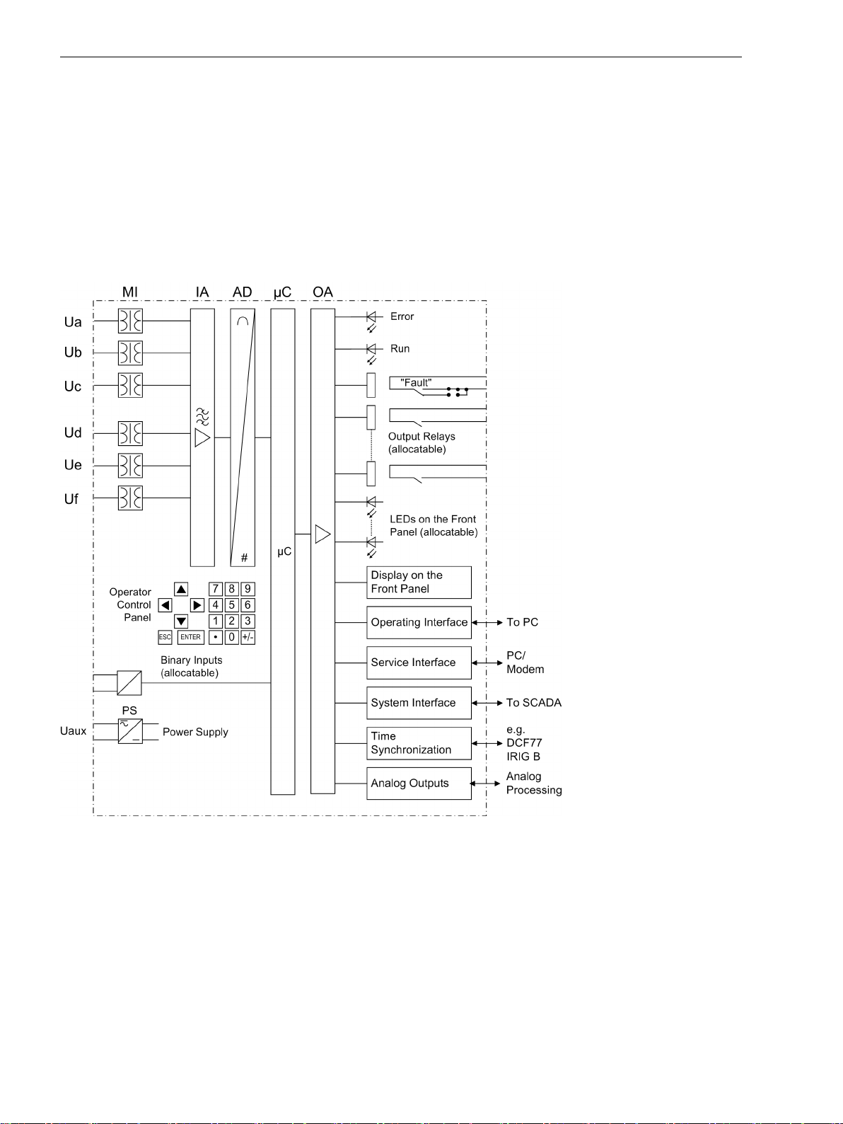
The multi-functional protection devices SIPROTEC 4 7VE61 and 7VE63 are equipped with a powerful microprocessor. All tasks, such as the acquisition of the measured quantities, issuing of commands to circuit
breakers and other primary power system equipment, are processed fully digitally. Figure 1-1 shows the basic
structure of the device.
The measuring inputs (MI) are galvanically isolated, transform the voltages from the primary transformers and
adapt them to the internal processing level of the device. Six voltage inputs are available in the MI section.
[hardwarestruktur-ve6-200303-kn, 1, en_GB]
Figure 1-1
The IA input amplifier group allows high impedance connection for analog input values and contains filters
optimized for measured value processing bandwidth and speed.
The AD analog digital converter group contains high resolution ΣΔ digital converters (22 bits) and memory
components for data transfer to the microcomputer.
Micro Computer System
The implemented software is processed in the microcomputer system (μC) Essential functions are:
16 SIPROTEC 4, 7VE61 and 7VE63, Manual
Hardware structure of the digital Multifunction Paralleling Devices 7VE61 and 7VE63 (maximal
configuration)
C53000-G1176-C163-3, Edition 10.2017

Filtering and preparation of the measured quantities
•
Continuous monitoring of the measured quantities
•
Processing of the algorithms for the synchrocheck function
•
Monitoring of the pickup conditions for the individual protective functions
•
Interrogation of limit values and sequences in time
•
Controlling signals for logic functions
•
Output of control commands for switching devices
•
Signalling of synchronization and protection behaviour via LEDs, LCD, relays or serial interfaces
•
Recording of messages, fault data and fault values for analysis
•
Management of the operating system and the associated functions such as data recording, real-time
•
clock, communication, interfaces, etc.
Binary Inputs and Outputs
Binary inputs and outputs from and to the computer system are routed via the I/O modules (inputs and
outputs). The computer system obtains the information from the system (e.g remote resetting) or the external
equipment (e.g. blocking commands). Outputs are mainly commands that are issued to the switching devices
and messages for remote signalling of events and states.
Introduction
1.1 Overall Operation
Front Elements
Light-emitting diodes (LEDs) and a display (LCD) on the front panel provide information on the functional
status of the device and report events, states and measured values. The integrated control keys and numeric
keys in conjunction with the LCD enable local interaction with the device. They allow the user to retrieve any
kind of information from the device such as configuration and setting parameters, operational indications and
fault messages (see also /1/ SIPROTEC 4 System Manual) and to change setting parameters.
Serial Interfaces
A personal computer running the DIGSI software can be connected to the serial
the front panel to conveniently operate all device functions.
A separate service interface can be provided for remote communication with the device via a personal
computer using DIGSI 4. This interface is especially well suited for a permanent connection of the devices to
the PC or for operation via a modem.
All data can be transferred to a central control or monitoring system via the serial
protocols and physical arrangements are available for this interface to suit the particular application.
A further interface is provided for
sources.
Further communication protocols can be implemented via additional interface modules.
Analog Outputs
Depending on the ordering variant and configuration, ports B and D can be equipped with analog output
modules for the output of selected measured values (0 to 20 mA or 4 to 20 mA).
Power Supply
operator interface (PC port) on
system interface. Various
time synchronization of the internal clock through external synchronization
The functional units described are supplied by a power supply PS with the necessary power in the different
voltage levels. Voltage dips may occur if the voltage supply system (substation battery) becomes shortcircuited. Usually, they are bridged by a capacitor (see also Technical Data).
SIPROTEC 4, 7VE61 and 7VE63, Manual 17
C53000-G1176-C163-3, Edition 10.2017

Introduction
1.2 Application Scope
1.2
Application Scope
The digital paralleling devices 7VE61 and 7VE63 of the SIPROTEC 4 family are multifunctional compact
devices, which may be used for parallel switching systems and generators. Its technical version warrants a
high security during parallel switching. This can be reached by means of the 11/2 channel measurement tech-
nique in device 7VE61 or the two-channel measurement technique in 7VE63 and a special hardware design.
Additionally, numerous monitoring functions serve as support.
Except for the synchronizing functions, in the devices 7VE61 and 7VE63 are available optional voltages and
frequency functions. Thus, the devices can be used for the protection function and for network decoupling
tasks.
The devices are recommended for the different applications:
7VE61:
Synchrocheck monitoring for systems and manual synchronization. In this option a total of 3 synchron-
•
izers can parallel operate.
Parallel switching for systems
•
Systems Disconnection and Automatic Re-synchronization
•
Automatic synchronization of small to medium generators.
•
7VE63:
Operation with increased safety requirements through a two-channel feature
•
Parallel switching for high-voltage and extra high-voltage systems
•
Automatic synchronization of large generators
•
Operation of several synchronizers by a device (up to 8 are possible)
•
Visualization of the condition system through a graphic display and local control.
•
Synchronization Functions
The devices recognize automatically the operating conditions and react depending on the pre-settings.
In the operation mode “Synchrocheck” will be checked the validity of a restart according to different
•
considerations.
In the operation mode “Switching Synchronous Systems” will be determined the frequency difference
•
with high accuracy. The connection will take place if the difference frequency is for a long time near to 0.
If asynchronous conditions are available as in the case of synchronization for generators and systems,
•
thus the speed can bring near automatically at the system frequency and the generator voltage at the
system voltage. A considering factor of the circuit breaker closing time is that the generator will be
switched to a point of synchronism.
A very high security for recognition of a de-energized line or bus is achieved via the multi-voltage circuit
•
and the multiple inquiries of the voltage. As a result, a connection of the network is trouble-free reestablished.
Protection and Automation Functions
Except for the synchronizing functions, in the devices 7VE61 and 7VE63 are available optional voltages and
frequency functions. Thus, the devices can be used for the protection function and for network decoupling
tasks.
The devices include the following basic functions:
Overvoltage protection U>
•
Undervoltage protection U<
•
Overfrequency f>
•
Underfrequency protection f<
•
Rate-of-frequency df/dt>; –df/dt<
•
18 SIPROTEC 4, 7VE61 and 7VE63, Manual
C53000-G1176-C163-3, Edition 10.2017

Vector jump protection Δφ
•
Fast threshold supervision of the voltages (U>; U<)
•
Control Functions
The device is equipped with control functions which operate, close and open, switchgear via the integrated
operator panel, the system interface, binary inputs, and using a personal computer with DIGSI software.
The status of the primary equipment can be transmitted to the device via auxiliary contacts connected to
binary inputs. The present status (or position) of the primary equipment can be displayed on the device, and
used for interlocking or plausibility monitoring. The number of the operating equipment to be switched is
limited by the binary inputs and outputs available in the device or the binary inputs and outputs allocated for
the switch position indications. Depending on the primary equipment being controlled, one binary input
(single point indication) or two binary inputs (double point indication) may be used for this process.
The capability of switching primary equipment can be restricted by a setting associated with switching
authority (Remote or Local), and by the operating mode (interlocked/non-interlocked, with or without password request).
Processing of interlocking conditions for switching (e.g. system interlocking) can be established with the aid of
integrated, user-configurable logic functions.
Messages and Measured Values; Fault Recording
The indication list provides information about conditions in the power system and the device. Measurement
quantities and values that are calculated can be displayed locally and communicated via the serial interfaces.
Device messages can be allocated to a number of LEDs, externally processed via output contacts, linked with
user-definable logic functions and/or issued via serial interfaces.
During a generator or network fault (fault in the power system), important events and state changes are
stored in a fault annunciation buffer. The instantaneous or rms measured values during the fault are also
stored in the device and are subsequently available for fault analysis.
Introduction
1.2 Application Scope
Communication
Serial interfaces are available for the communication with operating, control and memory systems.
Front Interface
A 9-pin DSUB socket on the front panel is used for local communication with a personal computer. By means
of the SIPROTEC 4 operating software DIGSI, all operational and evaluation tasks can be executed via this
ator interface, such as specifying and modifying configuration parameters and settings, configuring userspecific logic functions, retrieving operational and fault messages and measured values, readout and display of
fault recordings, querying of devices statuses and measured values.
Rear Interfaces
Depending on the individual ordering variant, additional interfaces are located at the rear side of the device.
They serve to establish an extensive communication with other digital operating, control and memory components:
The
this reason, remote operation is possible via personal computer and the DIGSI operating software, e.g. to
operate several devices via a central PC.
The
can be operated via data lines or fibre optic cables. Several standard protocols are available for the data
transfer:
•
oper-
service interface can be operated via electrical data lines and also allows communication via modem. For
system interface ensures the central communication between the device and the substation controller. It
IEC 61850
An EN 100 module allows to integrate the devices into 100 Mbit Ethernet communication networks used
by process control and automation systems and running IEC 61850 protocols. In parallel to the process
control integration of the device, this interface can also be used for communication with DIGSI and for
inter-relay communication via GOOSE.
SIPROTEC 4, 7VE61 and 7VE63, Manual 19
C53000-G1176-C163-3, Edition 10.2017

Introduction
1.2 Application Scope
IEC 60870-5-103
•
This profile also integrates the devices into the substation automation systems SINAUT LSA and SICAM.
Profibus DP
•
This protocol of automation technology allows transmission of indications and measured values.
Modbus ASCII/RTU
•
This protocol of automation technology allows transmission of indications and measured values.
DNP 3.0
•
This protocol of automation technology allows transmission of indications and measured values.
It is also possible to provide an analog output (2 x 20 mA) for output of measured values.
•
20 SIPROTEC 4, 7VE61 and 7VE63, Manual
C53000-G1176-C163-3, Edition 10.2017

Introduction
1.3 Characteristics
1.3
General Characteristics
Characteristics
Powerful 32-bit microprocessor system.
•
Complete digital measured value processing and control, from sampling and digitalizing of measured
•
values up to the switchon and switchoff decisions for power breakers and other switchgear.
Total electrical separation between the internal processing stages of the device and the external trans-
•
former, control and DC supply circuits of the system because of the design of the binary inputs, outputs,
and the DC converters.
Easy device operation via an integrated operator panel or by means of a connected personal computer
•
with the DIGSI operating program.
Continuous computation and display of measured quantities.
•
Storage of fault messages and instantaneous or rms values for fault recording.
•
Continuous monitoring of measured values as well as of the hardware and software of the device.
•
Communication with central control and memory storage equipment via serial interfaces, optionally via
•
data cable, modem, or optic fibre lines.
Battery-buffered real time clock that can be synchronized with an IRIG-B (or DCF77) signal, binary input
•
signal, or system interface command.
Statistics: Starting and trip commands from the device are counted.
•
Commissioning aids such as connection check, field rotation check, status display of all binary inputs and
•
outputs, and test measurement recording.
Synchrocheck, Dead Line/Bus
Settable minimum and maximum voltage
•
Verification of the synchronous conditions or the de-energized state is also possible before the manual
•
closing of the circuit breaker, with separate limit values
Fast measuring of voltage difference U
•
Measurement via transformer (integrated vector group adaptation)
•
Measuring voltages optionally for phase-phase or phase-earth.
•
Controlling Synchronous Networks
Fast measuring of the voltage difference U
•
The operating mode is automatically activated (pre-settings), if the frequency difference is f
•
Measurement via transformer (integrated vector group adaptation)
•
Measuring voltages optionally for phase-phase or phase-earth.
•
Controlling Asynchronous Networks
Fast measuring of the voltage difference U
•
Consideration of the angle difference with prediction of the point of synchronism
•
Measurement via transformer (integrated vector group adaptation)
•
Measuring voltages optionally for phase-phase or phase-earth.
•
, of the phase angle difference α
diff
and of the phase angle difference α
diff
and of the frequency difference f
diff
and frequency difference f
diff
diff
≈ 0
diff
;
diff
diff
SIPROTEC 4, 7VE61 and 7VE63, Manual 21
C53000-G1176-C163-3, Edition 10.2017

Introduction
1.3 Characteristics
Undervoltage Protection 27
Two-stage undervoltage measurement for one of the 6 input voltages of the device
•
Separated tripping delay time
•
Settable drop-off to pickup for both stages
•
Overvoltage Protection 59
Two-stage overvoltage measurement for one of the 6 input voltages of the device
•
Separated tripping delay time
•
Settable drop-off to pickup for both stages
•
Frequency Protection 81 O/U
Monitoring on undershooting (f<) and/or overshooting (f>) with 4 frequency limits and delay times that
•
are independently adjustable
Insensitive to harmonics and abrupt phase angle changes
•
Settable undervoltage threshold.
•
Frequency Change Protection
Monitors whether the frequency overshoots (df/dt>) and/or undershoots (-df/dt<) a set limit value, with 4
•
individually settable limit values or delay times
Variable measuring windows
•
Coupling to frequency protection pickup
•
Settable undervoltage threshold.
•
Vector Jump
Sensitive phase jump detection to be used for network disconnection.
•
Analog Outputs
Output of up to four analog operational measured values (depending on the variant ordered).
•
Threshold Value Monitoring
6 freely assignable messages for threshold monitoring
•
Implementation of fast monitoring tasks via CFC.
•
User-defined Functions
Internal and external signals can be logically combined to establish user-defined logic functions
•
All common logic functions (AND, OR, NOT, Exclusive OR, etc.)
•
Time delays and limit value interrogations
•
Processing of measured values, including zero suppression, adding a knee characteristic for a transducer
•
input, and live-zero monitoring.
Breaker Control
Circuit breakers can be opened and closed manually via programmable function keys, via the system
•
interface (e.g. by SICAM or LSA), or via the operating interface (using a PC with DIGSI)
Feedback information on circuit breakers states via the breaker auxiliary contacts
•
Plausibility monitoring of the circuit breaker position and monitoring of interlocking conditions for
•
switching operations.
22 SIPROTEC 4, 7VE61 and 7VE63, Manual
C53000-G1176-C163-3, Edition 10.2017

Monitoring
1.3 Characteristics
Availability of the device is greatly increased by monitoring of the internal measurement circuits, auxiliary
•
power supply, hardware, and software
Monitoring of the input voltage circuit through double connection and opposite control
•
Checking of the phase sequence
•
Permanent monitoring of both closing relays BO1 and BO2
•
Opposite monitoring of the parallel starting algorithms.
•
Introduction
SIPROTEC 4, 7VE61 and 7VE63, Manual 23
C53000-G1176-C163-3, Edition 10.2017

24 SIPROTEC 4, 7VE61 and 7VE63, Manual
C53000-G1176-C163-3, Edition 10.2017

2
Functions
This chapter describes the individual functions of the SIPROTEC 4 device 7VE61 and 7VE63. It shows the
setting possibilities for each function in maximum configuration. Guidelines for establishing setting values
and, where required, formulae are given.
Based on the following information, it can also be determined which of the provided functions should be
used.
2.1 General 26
2.2 Paralleling Functions 35
2.3 Protection and Automation Functions 81
2.4 Undervoltage Protection 82
2.5 Overvoltage Protection 85
2.6 Frequency Protection 88
2.7 Rate-of-frequency-change protection 92
2.8 Jump of Voltage Vector 97
2.9 Threshold supervision 101
2.10 External Trip Functions 104
2.11 AnalogOutputs 106
2.12 Supervision 112
2.13 Function Control 118
2.14 Auxiliary Functions 120
2.15 Command Processing 131
SIPROTEC 4, 7VE61 and 7VE63, Manual 25
C53000-G1176-C163-3, Edition 10.2017
Functions
2.1 General
2.1
2.1.1
General
The settings associated with the various device functions may be modified by using the operating or service
interface in DIGSI. The procedure is set out in detail in the /1/ SIPROTEC 4 System Manual. For changing configuration parameters in the device, password no. 7 (for parameter set; default setting: 000000) is required.
Without the password, the settings may be read, but may not be modified and transmitted to the device.
The settings associated with the various device functions, limit values, etc. can be modified using the controls
on the front panel of the device or by using the operator interface with DIGSI in conjunction with a personal
computer. Password No. 5 (for single parameter; default setting: 000000).
Device
The device can issue a serie of general annunciations about itself and the substation. These annunciations are
listed in the following information list. Most annunciations are self-explanatory. The special cases are
described below:
Reset: Device is reset on each Power ON.
Initial Start: Initial start occurs after initialization of the device by DIGSI.
Restart: Restart occurs after loading a parameter set or after reset.
The indication of messages masked to LEDs, and the maintenance of spontaneous messages, can be made
dependent on whether the device has issued a trip command. In this situation, messages are not reported, if
one or more protective functions have picked up on a fault, but a trip signal has not been issued yet by the
7VE61 and 7VE63, because the fault was cleared by another device (for example, outside the own protection
range). These messages are then limited to faults in the line to be protected.
2.1.1.1
Spontaneous Fault Display
Resetting stored LEDs / relays
Setting Notes
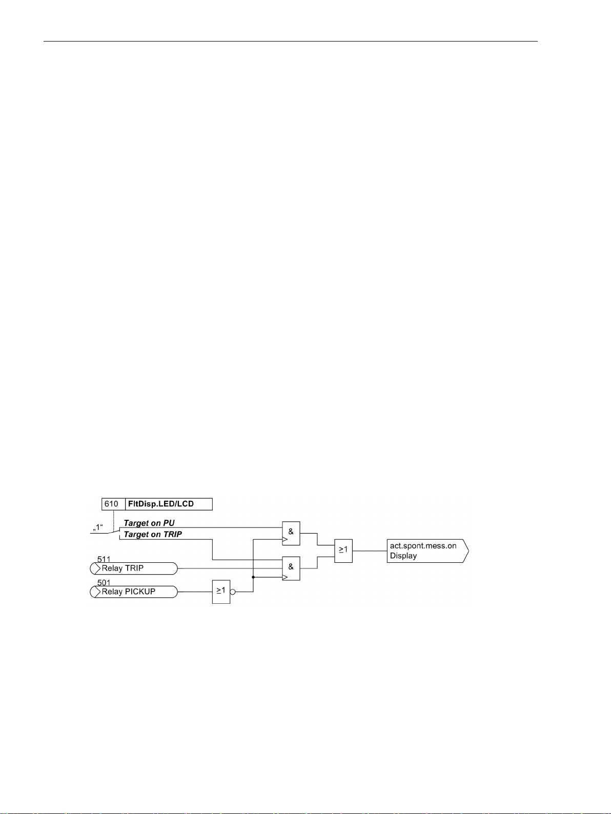
After a fault has occurred, the device display spontaneously shows the most important fault data. In address
610 FltDisp.LED/LCD you can select whether the spontaneous fault display is updated for each fault
(Target on PU) or only for faults that included a trip (Target on TRIP).
For devices with graphical display use parameter 611 Spont. FltDisp. to specify whether a spontaneous
fault display will be shown automatically YES) or not (NO). For devices featuring a text display such displays
will always appear a power system fault.
[logik-spondanmeld-display-081024, 1, en_GB]
Figure 2-1 Generation of spontaneous fault indications on the display
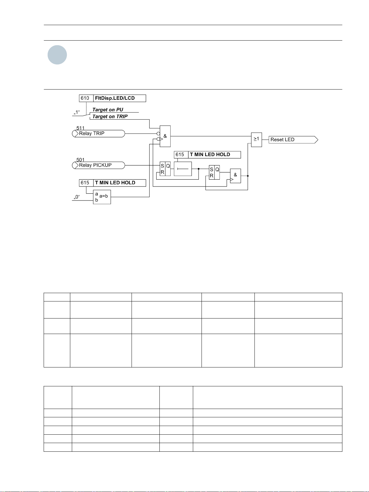
A new pickup will generally erase any stored LEDs/relays so that only the latest fault information is displayed at
any time. A time can be set in address 615 T MIN LED HOLD during which the stored LEDs and relays will
not be deleted. Any information occurring during that period of time will be linked via OR.
The option Target on TRIP in address 610 FltDisp.LED/LCD allows you to delete the information of the
most recent fault stored on LEDs and relays provided that this fault has not resulted in a trip command of the
device.
26 SIPROTEC 4, 7VE61 and 7VE63, Manual
C53000-G1176-C163-3, Edition 10.2017
i
i
Functions
2.1 General
NOTE
Setting address 610 FltDisp.LED/LCD to (Target on TRIP) is only reasonable if address 615 T MIN
LED HOLD is set to 0.
Die Einstellung der Adresse 610 FltDisp.LED/LCD auf (Target on TRIP) ist nur sinnvoll bei Einstellung von Adresse 615 T MIN LED HOLD auf 0.
[logik-ruecksetz-gesp-led-081024, 1, en_GB]
Figure 2-2 Creation of the resetting command for stored LEDs / relays
Default display of a 4-line display
After startup of the device featuring a 4-line display, measured values are displayed by default. The arrow keys
on the device front allow different displays of the measured values to be selected for the so-called default
display. The start image of the default display, which is displayed by default after startup of the device, can be
selected via parameter 640 Start image DD. The available representation types for the measured value are
listed in the Appendix.
2.1.1.2
Addr.
610 FltDisp.LED/LCD Target on PU
615 T MIN LED HOLD 0 .. 60 min 5 min Minimum hold time of latched
640 Start image DD image 1
2.1.1.3
Settings
Parameter Setting Options Default Setting Comments
Target on PU Fault Display on LED / LCD
Target on TRIP
LEDs
image 1 Start image Default Display
image 2
image 3
image 4
Information List
No.
- Reset LED IntSP Reset LED
- Test mode IntSP Test mode
- DataStop IntSP Stop data transmission
- UnlockDT IntSP Unlock data transmission via BI
- >Light on SP >Back Light on
SIPROTEC 4, 7VE61 and 7VE63, Manual 27
C53000-G1176-C163-3, Edition 10.2017
Information Type of
Information
Comments

Functions
2.1 General
No. Information Type of
Information
- SynchClock IntSP_Ev Clock Synchronization
- HWTestMod IntSP Hardware Test Mode
- Distur.CFC OUT Disturbance CFC
1 Not configured SP No Function configured
2 Non Existent SP Function Not Available
3 >Time Synch SP_Ev >Synchronize Internal Real Time Clock
5 >Reset LED SP >Reset LED
15 >Test mode SP >Test mode
16 >DataStop SP >Stop data transmission
51 Device OK OUT Device is Operational and Protecting
52 ProtActive IntSP At Least 1 Protection Funct. is Active
55 Reset Device OUT Reset Device
56 Initial Start OUT Initial Start of Device
67 Resume OUT Resume
69 DayLightSavTime OUT Daylight Saving Time
70 Settings Calc. OUT Setting calculation is running
71 Settings Check OUT Settings Check
72 Level-2 change OUT Level-2 change
73 Local change OUT Local setting change
110 Event Lost OUT_Ev Event lost
113 Flag Lost OUT Flag Lost
125 Chatter ON OUT Chatter ON
301 Pow.Sys.Flt. OUT Power System fault
302 Fault Event OUT Fault Event
320 Warn Mem. Data OUT Warn: Limit of Memory Data exceeded
321 Warn Mem. Para. OUT Warn: Limit of Memory Parameter exceeded
322 Warn Mem. Oper. OUT Warn: Limit of Memory Operation exceeded
323 Warn Mem. New OUT Warn: Limit of Memory New exceeded
545 PU Time VI Time from Pickup to drop out
546 TRIP Time VI Time from Pickup to TRIP
Comments
2.1.2
2.1.2.1
28 SIPROTEC 4, 7VE61 and 7VE63, Manual
EN100-Modul 1
Functional Description
An Ethernet Ethernet EN100-Module allows for the integration of the 7VE61 and 7VE63 into 100 Mbit
Ethernet communication networks used by process control and automation systems according to the IEC
61850 protocols. This standard enables integrated inter-relay communication without using gateways or
protocol converters. This allows open and interoperable use of SIPROTEC 4 devices even in heterogeneous
environments. In addition to the process control integration of the device, this interface can also be used for
communication with DIGSI and for interrelay communication via GOOSE messaging.
C53000-G1176-C163-3, Edition 10.2017
i
i
Functions
2.1 General
2.1.2.2
Interface selection
2.1.2.3
No. Information Type of
009.0100 Failure Modul IntSP Failure EN100 Modul
009.0101 Fail Ch1 IntSP Failure EN100 Link Channel 1 (Ch1)
009.0102 Fail Ch2 IntSP Failure EN100 Link Channel 2 (Ch2)
2.1.3
Setting Notes
No settings are required for operation of the Ethernet system interface module (IEC 61850 Ethernet EN100Modul). If the device is equipped with such a module (see MLFB), the module is automatically configured to
the interface available for it.
Information List
Comments
Information
Functional Scope
The devices 7VE61 and 7VE63 can have depending on the order variant except for the synchronization function over numerous protective and additional functions. The hardware and firmware is designed for this scope
of functions.
Also individual functions can be enabled or disabled during configuration. Functions not needed can be thus
be deactivated.
The available protection and synchronizing functions must be configured as Enabled or Disabled. For individual functions a choice between several alternatives is possible, as described below.
Functions that are configured as disabled are not processed by the 7VE61 and 7VE63: There are no indications, and corresponding settings (functions, limit values) are not queried during configuration.
2.1.3.1
Setting of the Functional Scope
2.1.3.2
Special Cases
Functional Description
Configuration settings can be entered using a PC and the software program DIGSI and transferred via the front
operator interface or the rear service interface. The procedure is described in detail in the /1/ SIPROTEC 4
System Manual.
Entry of password No. 7 (for parameter set) is required to modify configuration settings. Without the password, the settings may be read, but may not be modified and transmitted to the device.
The functional scope with the available alternatives is set in the Device Configuration dialog box to match
equipment requirements.
NOTE
Available functions and default settings depend on the device variant ordered (see Appendix A Ordering
Information and Accessories for details). Also, not all combinations of protective functions are possible
because of certain restrictions imposed by the hardware (see Section 2.1.1.1 Setting Notes).
Setting Notes
Most settings are self-explanatory. The special cases are described below.
If the setting group change function has to be used, address 103 Grp Chge OPTION must be set to
Enabled. In service, simple and fast change, over between up to four different groups of settings is possible.
Only one setting group may be selected and used if this option is Disabled.
SIPROTEC 4, 7VE61 and 7VE63, Manual 29
C53000-G1176-C163-3, Edition 10.2017

i
i
i
i
Functions
2.1 General
Parameter 104 FAULT VALUE is used to specify whether the oscillographic fault recording should record
Instant. values or RMS values. If RMS values are stored, the available recording time increases by
the factor 10.
The parameter 145 df/dt Protect. establishes for the frequency change protection whether this is to
contain two or four stages or is Disabled.
Up to 8 SYNC function groups are available for the synchronizing function. They are enabled in addresses 016x
(x = 1 ... 8). Parameters 161 SYNC function 1 to 168 SYNC function 8 are used in addition to preselect
the mode of operation:
1ph Sync check corresponds to the classical synchronizing function with in each case single-phase connection of the voltages to be compared.
3ph Sync check corresponds to the classical synchronizing function with in each case multi-phase connection of the voltages to be compared.
NOTE
A mixed parametrization of single-phase and three-phase synchrocheck between function groups is inadmissible and leads to an error indication.
1,5chan.Synchr
device. Connection is multiphase, processing of data command issuing is done 11/2-channel with the 7VE61 or
2-channel with the 7VE63.
NOTE
A mixed parametrization of three-phase synchrocheck and 11/2 or 2-channel synchronising function is
possible due to the identical connection.
If a function is not needed,Disabled is set. A synchronizing function group thus rendered ineffective is
excluded in the menu item Synchronization, all other groups are displayed. The maximum number of the
existing synchronising function groups is established by the device variant (see section “Function description
of the synchronizing function”).
2.1.3.3
Addr.
103 Grp Chge OPTION Disabled
104 FAULT VALUE Disabled
140 UNDERVOLTAGE Disabled
141 OVERVOLTAGE Disabled
142 FREQUENCY Prot. Disabled
145 df/dt Protect. Disabled
146 VECTOR JUMP Disabled
160 BALANC. (MLFB) Disabled
Settings
Parameter Setting Options Default Setting Comments
with the 7VE61 or 2chan.Synchr. with the 7VE63 corresponds to operation as a parallel
Enabled
Instant. values
RMS values
Enabled
Enabled
Enabled
2 df/dt stages
4 df/dt stages
Enabled
Enabled
Disabled Setting Group Change Option
RMS values Fault values
Enabled Undervoltage Protection
Enabled Overvoltage Protection
Enabled Over / Underfrequency Protection
2 df/dt stages Rate-of-frequency-change protec-
tion
Enabled Jump of Voltage Vector
Disabled Balancing Commands (Siemens
only MLFB)
30 SIPROTEC 4, 7VE61 and 7VE63, Manual
C53000-G1176-C163-3, Edition 10.2017

Addr. Parameter Setting Options Default Setting Comments
161 SYNC function 1 Disabled
Disabled SYNC Function group 1
1ph Sync check
3ph Sync check
1,5chan.Synchr
2chan.Synchr.
162 SYNC function 2 Disabled
Disabled SYNC Function group 2
1ph Sync check
3ph Sync check
1,5chan.Synchr
2chan.Synchr.
163 SYNC function 3 Disabled
Disabled SYNC Function group 3
1ph Sync check
3ph Sync check
1,5chan.Synchr
2chan.Synchr.
164 SYNC function 4 Disabled
Disabled SYNC Function group 4
3ph Sync check
1,5chan.Synchr
2chan.Synchr.
165 SYNC function 5 Disabled
Disabled SYNC Function group 5
3ph Sync check
2chan.Synchr.
166 SYNC function 6 Disabled
Disabled SYNC Function group 6
3ph Sync check
2chan.Synchr.
167 SYNC function 7 Disabled
Disabled SYNC Function group 7
3ph Sync check
2chan.Synchr.
168 SYNC function 8 Disabled
Disabled SYNC Function group 8
3ph Sync check
2chan.Synchr.
173 ANALOGOUTPUT B1 Disabled
Disabled Analog Output B1 (Port B)
Enabled
174 ANALOGOUTPUT B2 Disabled
Disabled Analog Output B2 (Port B)
Enabled
175 ANALOGOUTPUT D1 Disabled
Disabled Analog Output D1 (Port D)
Enabled
176 ANALOGOUTPUT D2 Disabled
Disabled Analog Output D2 (Port D)
Enabled
185 THRESHOLD Disabled
Enabled Threshold Supervision
Enabled
186 EXT. TRIP 1 Disabled
Enabled External Trip Function 1
Enabled
187 EXT. TRIP 2 Disabled
Enabled External Trip Function 2
Enabled
188 EXT. TRIP 3 Disabled
Enabled External Trip Function 3
Enabled
Functions
2.1 General
SIPROTEC 4, 7VE61 and 7VE63, Manual 31
C53000-G1176-C163-3, Edition 10.2017

Functions
2.1 General
Addr. Parameter Setting Options Default Setting Comments
189 EXT. TRIP 4 Disabled
Enabled
Enabled External Trip Function 4
2.1.4
2.1.4.1
General
Rated System Frequency
Command Duration
2.1.4.2
Addr.
270 Rated Frequency 50 Hz
280 TMin TRIP CMD 0.01 .. 32.00 sec 0.15 sec Minimum TRIP Command Duration
Power System Data 1
The P.System Data 1 include settings associated with all functions rather than a specific synchronizing,
protection, control or monitoring function.
Setting Notes
The Power System Data 1 can be changed from the operator or service interface with a personal computer
using DIGSI.
In DIGSI double-click on Settings to display the relevant selection.
The nominal frequency of the system is set in Address 270 Rated Frequency. The factory setting of the
model variant must only be changed if the device is to be used for a purpose other than intended when
ordering.
In address 280 the minimum trip command duration TMin TRIP CMD is set. This duration is valid for all
protection functions which can issue a trip command.
Settings
Parameter Setting Options Default Setting Comments
50 Hz Rated Frequency
60 Hz
16,7 Hz
2.1.4.3
No.
361 >FAIL:Feeder VT SP >Failure: Feeder VT (MCB tripped)
501 Relay PICKUP OUT Relay PICKUP
511 Relay TRIP OUT Relay GENERAL TRIP command
5588 >FAIL: VT Ua SP >Failure: VT Ua (MCB tripped)
5589 >FAIL: VT Ub SP >Failure: VT Ub (MCB tripped)
5590 >FAIL: VT Uc SP >Failure: VT Uc (MCB tripped)
5591 >FAIL: VT Ud SP >Failure: VT Ud (MCB tripped)
5592 >FAIL: VT Ue SP >Failure: VT Ue (MCB tripped)
5593 >FAIL: VT Uf SP >Failure: VT Uf (MCB tripped)
25007 U1: VI Voltage U1 at switch on
25008 f1: VI Frequency f1 at switch on
25009 U2: VI Voltage U2 at switch on
25010 f2: VI Frequency f2 at switch on
32 SIPROTEC 4, 7VE61 and 7VE63, Manual
Information List
Information Type of
Information
Comments
C53000-G1176-C163-3, Edition 10.2017

Functions
2.1 General
No. Information Type of
Information
25011 dU: VI Voltagedifference at switch on
25012 df: VI Frequencydifference at switch on
25013 dα: VI Angledifference at switch on
25059 >Break. Contact SP >Breaker contacts
2.1.5
2.1.5.1
General
Change Group
Up to four independent setting groups can be created for establishing protection function settings.
Setting groups enable the user to save the various function settings for different applications and to retrieve
these settings quickly. All setting groups are stored in the device. Only one setting group is active.
During operation the user can locally switch between setting groups, using the operator panel, binary inputs
(if so configured), the service interface per PC, or via the system interface.
A setting group includes the setting values for all functions that have been selected as Enabled during
configuration (see Section 2.1.1.1 Setting Notes). In 7VE61 and 7VE63 devices, four independent setting
groups (A to D) are available. Whereas setting values may vary, the selected functions of each setting group
remain the same.
Setting Notes
Comments
If multiple setting groups are not required, group A is the default selection. Then, the rest of this section is not
applicable.
If the changeover option is desired, group changeover must be set to Grp Chge OPTION = Enabled
(address 103) when the function extent is configured. For the setting of the function parameters, each of the
required setting groups A to D (a maximum of 4) must be configured in sequence. The SIPROTEC 4 System
Description gives further information on how to copy setting groups or reset them to their status at delivery
and also how to change from one setting group to another.
Subsection 3.1 Mounting and Connections of this manual tells you how to change between several setting
groups externally via binary inputs.
2.1.5.2
Addr.
302 CHANGE Group A
2.1.5.3
No.
- P-GrpA act IntSP Setting Group A is active
- P-GrpB act IntSP Setting Group B is active
- P-GrpC act IntSP Setting Group C is active
- P-GrpD act IntSP Setting Group D is active
7 >Set Group Bit0 SP >Setting Group Select Bit 0
Settings
Parameter Setting Options Default Setting Comments
Group A Change to Another Setting Group
Group B
Group C
Group D
Binary Input
Protocol
Information List
Information Type of
Information
Comments
SIPROTEC 4, 7VE61 and 7VE63, Manual 33
C53000-G1176-C163-3, Edition 10.2017

Functions
2.1 General
No. Information Type of
Comments
Information
8 >Set Group Bit1 SP >Setting Group Select Bit 1
34 SIPROTEC 4, 7VE61 and 7VE63, Manual
C53000-G1176-C163-3, Edition 10.2017

Functions
2.2 Paralleling Functions
2.2
2.2.1
2.2.1.1
Paralleling Functions
The paralleling facility is the main function of the 7VE61 and 7VE63 devices. A high degree of reliability and
flexible adaptation to power system conditions allow different application areas. The following modes of operation are covered:
Synchrocheck
•
Switching Synchronous Systems
•
Switching Asynchronous Systems
•
Switching to dead line/dead busbar
•
Functional Description
When connecting generator and power system or two power systems, the synchronism check verifies that the
switching does not endanger the generator or the stability of the power system. For this purpose the voltage
vectors of the power system sections to be synchronised are checked within definite limits for compatibility.
Connection and definitions
Depending on the device variants, parametrization possibilities are provided for up to eight different synchronizing functions. The following describes the function and mode of operation for the first synchronising function (SYNC Function group 1). The same applies to function groups 2 to 8.
For proper functioning of the parallel devices 7VE61 and 7VE63 special conditions must be adhered to on
connection to the voltage transformer circuits and the power breaker close coils.
Figure 2-3 shows a three-phase connection. The measuring voltage is the phase-to-phase voltage U
used for the synchronization function. The voltage inputs Ua and Ub can be connected on the side 1 and the
voltage inputs Ud and Ue on the side 2. Since the winding sense of the voltage inputs Ub and Ue is changed
opposite the other inputs, the connection of the corresponding second voltage input (Ub or Ue) takes place in
inverse polarity (also anti-parallel). The sum of these voltages rotated by 180° to each other on each side must
be zero. This allows a steady check of the measurement circuit as well as of the whole measuring channel of
the voltage transformer circuit up to the recording of the measuring values.
At each third measurement input, for three-phase power systems a second phase-to-phase voltage (voltage
U
) can be connected which — together with each first voltage — allows the phase sequence to be checked.
L23
For two or single-phase power systems (16.7 Hz) the third measurement input remains unused (see connection example in the appendix).
An den jeweils dritten Messeingang kann bei Dreiphasennetzen eine zweite verkettete Spannung (Spannung
U
) angeschlossen werden, die – zusammen mit der jeweils ersten Spannung – die Kontrolle der Drehfelder
L23
ermöglicht. Bei Zwei- oder Einphasennetzen (16,7 Hz) bleibt der dritte Messeingang unbenutzt (siehe
Anschlussbeispiel im Anhang A.3).
The device can also be connected to a V-connection (open delta connection) using two phase-phase voltages
(see connection example in the appendix).
which is
L12
SIPROTEC 4, 7VE61 and 7VE63, Manual 35
C53000-G1176-C163-3, Edition 10.2017

Functions
2.2 Paralleling Functions
[ve6-standardanschluss-dreiphasig-mdrehfeld-030203-kn, 1, en_GB]
Figure 2-3
Connection to three phase voltage transformers (standard connection)
A possible special connection category for the synchrocheck is explained further below in this Function
Description
For the realization of the two-channel feature and the use of the monitoring functionality, the output relays
BO1 (R1) and BO2 (R2) must be exclusively used for the CLOSE command. A typical connection is shown in
Figure 2-4.
[ve6-ein-relais-anschaltung-090403-kn, 1, en_GB]
Figure 2-4 Interconnection of relays for the ON command
Important for understanding of the following versions is the definition of the values. According toFigure 2-3
side 1 is the reference side. This is indexed with 1. This results for voltage U1 the frequency f1 and the phase
angle α1. For the side to be synchronised index 2 is defined. The electrical values of side 2 are then the
voltage U2, the frequency f2 and the phases angle α2.
Formation of the difference values requires definition of the absolute measurement error (Δx = measure value
– true value). The reference value and thus the true value is side 1. This results in the following calculation
regulations:
Difference voltage dU = U2 – U1
A positive result means that voltage U2 is larger than voltage U1. Otherwise the result is negative.
Difference frequency df = f2 – f1
A positive result means that for example the generator frequency is greater than the power system frequency.
This would be the oversynchronous case. If undersynchronous conditions prevail, the result of the difference
frequency is negative.
36 SIPROTEC 4, 7VE61 and 7VE63, Manual
C53000-G1176-C163-3, Edition 10.2017

Functions
2.2 Paralleling Functions
Phase angle difference dα = α2 – α1
Display is limited to ±180°. A positive result means that α2 leads by a maximum of 180°. A negative result
causes α2 to lag by a maximum of 180°. Details are shown in Figure 2-5. Phase angle α1 was set on the zero
axis as a reference system.
If synchronous networks are present and the frequency f2 is greater than f1, this means that the angle dα
changes from negative value to zero and then to a positive value. As illustrated in Figure 2-5, this is a counterclockwise rotation (= mathematically positive). With f2 < f1 the rotation is in the counter-clockwise. By visualization of the synchroscope in the WEB-Browser (see “Commissioning Aids”) the illustration is rotated in
Figure 2-5 in order to keep the usual phase sequence from conventional synchroscope (f2 > f1 — correction
angle in counter-clockwise rotation).
2.2.1.2
[ve6-phasenwinkeldifferenz-090403-oz, 1, en_GB]
Figure 2-5 Phase angle difference representation dα
For the setting parameters only positive values were used. For unequivocal characterisation of the setting
parameters the above mentioned value description was modified somewhat. Inequalities were used. The
representation is explained using a difference voltage example. To allow asymmetrical settings, two setting
thresholds are required.
A positive value for dU produces the condition U2 > U1. The parameter for the setting e.g. for asynchronous
power systems is dU ASYN U2>U1 (address 6130). For the second setting parameter which corresponds to a
negative dU, the inequality U2 < U1 applies. The associated setting parameter for asynchronous power
systems is dU ASYN U2<U1 (address 6131).
An analogous procedure was used for the difference frequency and the difference phase angle.
Synchronization via Transformers
There are also power systems where in addition a power transformer is located between the voltage measuring points of the circuit breaker being synchronised. This is possible for example with unit connections if
synchronization is done using the high-voltage circuit breaker (see Figure 2-6).
SIPROTEC 4, 7VE61 and 7VE63, Manual 37
C53000-G1176-C163-3, Edition 10.2017

i
i
Functions
2.2 Paralleling Functions
[darstellung-trafostufenschaltung-100403-kn, 1, en_GB]
Figure 2-6 Synchronisation via a transformer
The 7VE61 and 7VE63 device takes into consideration via the entry of the parameter 6122 ANGLE ADJUSTM..
the angle rotation and thus the vector group for the transformer. For transformers with tap changer the
setting can be also notified to the device for example via binary code and other codes (implemented in the
7VE63). In the event of deviations from the rated transformation ratio the voltage amplitude is adapted
accordingly.
Apart from the via the binary input, the tap changer information to the device can also be transmitted via the
serial interface (e.g. Profibus DP). Logical allocation of binary tap changer information from the bus to the
logical binary inputs is to be implemented via the CFC (Connect module).
2.2.1.3
NOTE
For transformers with tap changers for a quadrature or phase angle control the additional angle rotation in
the voltage cannot be corrected. Here synchronism should always be done with the rated position of the
tap changer (no angle rotation). Unrestricted synchronisation is always possible if voltage transformers are
located on both sides of the circuit breaker.
11/2– and 2–channel Version
A high degree of safety and reliability are achieved in the devices 7VE61 and 7VE63 by virtue of the multichannel capability. For this purpose a two-out of-two decision is implemented. Two independent conditions
must always be fulfilled for the closure command. For the 7VE61 and 7VE63 devices and the two-out of-two
decision is implemented differently. The following diagram shows the principal structure of the two versions
used.
[ve6-mehrkanaligkeit-030205-kn, 1, en_GB]
Figure 2-7 Design of a multi-channel redundancy
To distinguish the two versions, the terms 11/2-channel capability and 2-channel capability were introduced.
They are explained in more detail in the following.
38 SIPROTEC 4, 7VE61 and 7VE63, Manual
C53000-G1176-C163-3, Edition 10.2017

11/2-channel Version
In the 11/2-channel version of the 7VE61 the paralleling function issues the closure command. The synchrocheck function operates as an enable criterion and is set coarsely in the monitoring limits. The existing
dependences for the setting values of the enable angle, the permissible frequency difference and the circuit
breaker closing time make a little narrow the working range of the 7VE61 compared with the 2 channels
7VE63 ( see the Seting Notes of the synchocheck).
2-channel Version
In 2-channel version of the 7VE63 two procedures independent of one another operate in parallel. The closure
command is issued if both procedures decide for closure. The uniformity of the two channel device design is
shown in the following figure.
Functions
2.2 Paralleling Functions
[ve6-zweikanaligkeit-030205-kn, 1, en_GB]
Figure 2-8 2- channel version
Uniform Multichannel Redundancy
To ensure high safety and reliability, not only the software was developed in diverse forms, but also essential
hardware components were duplicated. In accordance with Figure 2-8 or Figure 2-3 the voltage inputs (U1
and U1 as well as U2 and U2) are duplicated and fed to two analog/digital converters. Measurement procedure
1 operates exclusively with voltages U1 and U2 and measurement procedure 2 with voltages rotated by 180°
U1 or U2). In the 11/2 channel version in measurement procedure 1 the synchrocheck function is applied and
(
in measurement procedure 2 the parallel switch function. With the 2-channel version in measurement proce-
dures 1 and 2 different parallel switch algorithms are processed.
If both procedures decide for closure, enabling is allocated for activating the breaker semiconductors. Two
closure relays are activated each by two semiconductors. This avoids overfunctioning by semiconductor
shorting. Further safety is provided acc. to Figure 2-8 by the relay activation using the cross measurement
procedure. The closure coils are activated by the contacts of the two relays. External interconnection is to be
done such that the plus pole and the minus pole are separately switched.
Measurement Methods
To conform to multichannel redundancy, two diverse measurement algorithms are used. This excludes overfunctioning due to systematic errors. At the same time measurement procedures of different programmers are
used, processed in independent tasks, and use different memory parts.
SIPROTEC 4, 7VE61 and 7VE63, Manual 39
C53000-G1176-C163-3, Edition 10.2017

Functions
2.2 Paralleling Functions
The different versions of the FIR-Filter (Finite Impulse Response), takeover a central function which is characterised by a defined impulse response, linear phase and high stability. The filter was so designed that DC
components and higher frequency disturbance signals which differ from the rated frequency, are effectively
suppressed. In addition the "decimation filter" incorporated in the analog digital converter is of help in disturbance signal suppression.
The following table gives an overview of measurement conversion.
Table 2-1 Overview of the two measurement procedures
Voltage
Measurement
Frequency
Measurement
Angle
Measurement
Connection
“asynchronous
power systems”
Measurement procedure 1 Measurement procedure 2
With two orthogonal FIR filters (filter
length 1 cycle and frequency correction)
the real and imaginary components of the
voltage vector are established. This
produces the amplitude value (fundamental harmonic).
With two orthogonal FIR filters (filter
length 1.25 cycles implemented using two
displaced lowpass filters and frequency
correction) the real and imaginary components of the voltage vector are established. This produces the amplitude value
(fundamental harmonic).
The frequency is calculated using a special
filter procedure with series 60th order
bandpass (3 cycles filter). The measurement procedure tolerates deviations from
the rated frequency.
The arctan of the angle is established
using the frequency corrected vector of
the above FIR filter.
The connection condition is the angle,
with the current measure value Δf the
closure time of the breaker is converted to
an angle, if the measured angle agrees
with the “CB angle” the closure command
The frequency is determined by an angle
difference measurement of the voltage
vector(delta interval three cycles). Deviations from the rated frequency are
corrected accordingly.
The arctan of the angle is established
using the frequency corrected vector of
the above FIR filter.
Connection condition is the time, using Δf
Δα is converted to a time; if the time
proportional to the angle agrees with the
CB closure time, the closure command
results.
results.
2.2.1.4
Monitoring Procedure
In Figure 2-8 in addition essential monitoring procedures are shown which are explained in the following. The
measure values are fed to 2 analog/digital converters (ADC) where the second ADC processes value rotated
by180° (
U1; U2). The monitoring procedures checke the entire transformer circuits including internal acquisi-
tion and storage, for plausibility, and block the measurement procedures in the event of deviations.
With the Sampled value monitoring for each sampled value the following equations are processed for the
two voltages U1 and U2:
I u1(k) +
I u2(k) +
u1(k) I ≤ Δu
u2(k) I ≤ Δu
If an admissible voltage Δu is exceeded, an error must be present in measured value acquisition or storage
(voltage transformer, ADC, memory). If this fault occurs several times, a disturbance indication (25037
Fail Ch U1
; 25038
Sync Fail Ch U2
) is created for each channel and the synchronizing functions are
Sync
blocked.
This channel monitoring is only used with configuration as a parallel switching device. This monitoring is not
provide for single-phase synchrocheck applications.
The Jump monitoring (data continuity monitoring) is intended to register a flipping of higher value bits which
can falsely produce a large sampled value and thus lead to amplitude and angle measurement errors. Possible
causes are: ADC errors, memory errors or induced disturbances (EMC). Consecutive sampled values are monitored in accordance with the following relationship.
I ua(k) – ua(k–1) I ≤ Δu
I ub(k) – ub(k–1) I ≤ Δu
I ud(k) – ud(k–1) I =Δu
max
max
max
40 SIPROTEC 4, 7VE61 and 7VE63, Manual
C53000-G1176-C163-3, Edition 10.2017

Functions
2.2 Paralleling Functions
I ue(k) – ue(k–1) I = Δu
If the number of faults per cycle are exceeded, the closure command is blocked and an indication issued
(25054
This monitoring is only used with configuration as a parallel switching device. This function is not provide for
single-phase synchrocheck applications.
Not shown in Figure 2-8, an additional ADC monitoring is effective for inputs U1 and U2. This monitoring
operates for all connection variants. For this purpose each free fourth analog channel of the ADC is interconnected. For each sampled value of the voltage inputs Ua (corresponds to U1) and Ue (corresponds to U2),
consistency with the original channels is checked for the other ADC.
I ua(k)
I ue(k)
If the limit is transgressed, the synchronizing function is blocked and at the same time the device is terminated
(live contact is activated), since an error is assumed in the ADCs. An alarm is issued in parallel with this (25036
Error ADC
The Phase sequence check detects connection and other faults. It is effective if a multi-phase voltage connection results (see Figure 2-3) and the parameter 6113 PHASE SEQUENCE is set to L1 L2 L3 for a clockwise
phase sequence or L1 L3 L2 for an anticlockwise phase sequence. If different phase sequences or those
other than the setting are established at inputs U1 and U2, the synchronising function is blocked and corresponding indications are issued (25039
purposes the phase sequence appears as an operational measured value for both inputs.
The measurement algorithms and logic functions are in to be found in the displayed measure procedures 1
and 2. Different measurement procedures are used in accordance with the two-channel capability in order to
exclude overfunctioning caused by process conditioned (systematic) errors. In addition other procedures are
effective in the background. The closure monitoring checks the Consistency of both measurement procedures. If both procedures do not result in the closure command within a prescribed period, this causes a rejection and an indication (
Additionally, it is monitored whether both measuring procedures are operating in the same mode (SYNCHRONOUS or ASYNCHRONOUS). If this is not the case, message
commands can be issued. Should this condition prevail for one minute, the synchronization is terminated with
the fault message e.g.
The start input must be activated again for continuation of synchronisation. These monitorings are operative
with two channel mode.
Overfunctionings of Relay triggering are avoided by the two-channel activation of both closure relays. With
this both measurement procedures cross activate the semiconductors. In addition in the background coil activation is monitored. For this purpose the semiconductors are activated individually and the response is read
back. Both interruptions and a shorted semiconductor are detected. Detected errors result in a blocking of the
device and a corresponding indication (
Furthermore monitoring is supported by a Plausibility settings check as well as by the Number of synchro-
nizing function groups:
•
•
•
•
On absent or multiple selection of synchronizing function group the indication
synchronisation start in addition the indication
In the event of configurations errors the indication
Fail.Conf.
Furthermore, specific thresholds and settings of the selected function group are checked with regard to parametrization. If there is a condition which is not plausible, the indication
cation
If a voltage transformer fault appears at the device via binary inputs (mcb tripping)
Sync Fail Data
– ua(k)
ADU1
– ue(k)
ADU1
).
Check for uniquivocality of the function group (only one in each case may be selected)
Check of configuration (mixed configuration single-phase/multi-phase is not permitted)
Parametrization check (valid limits)
Evaluation of monitoring functions
appears.
Sy1 ParErr
>FAIL: VT Uf
are allocated whose associated voltages Ua to Uf are referred to for synchronization.
max
).
I ≤ Δu
ADU2
I ≤ Δu
ADU2
SyncSeq U1 fail
Sync sup. α
Sy1 Error
) is issued.
.
Error Relay R1
Sync FG-Error
Sy1 active
is output additionally.
, likewise synchronization is not started. Note here that of the 6 available binary inputs those
; 25040
Sync sup.asym.
or
SyncSeq U2 fail
is generated and no close
Error Relay R2
Sy1 active
is output.
drops out and the indication
Sy1 active
). For checking
) is issued.
drops out. On
Sync
drops out and the indi-
>FAIL: VT Ua
to
SIPROTEC 4, 7VE61 and 7VE63, Manual 41
C53000-G1176-C163-3, Edition 10.2017

Functions
2.2 Paralleling Functions
During privatisation of the device (indication
reasons.
All these indications lead to a stopping and resetting of the synchronising function.
A summary of all monitorings is given in Section 2.12 Supervision.
2.2.1.5
Synchronization of Power Units
Multiple Synchronizing Points
Depending on the scope of delivery (see Table 2-2) multiple synchronising points can be operated. The setting
parameters are deposited here for each circuit breaker being synchronised, in so-called synchronising function
groups. In the maximum variant the 7VE63 operates up to 8 synchronising points. Selection uses either binary
inputs or the serial interface.
Table 2-2 Maximum number of synchronising function groups
Device 7VE61* 7VE63*
14. Order No position A B or C D A B or C D
Number of Sync function groups 3 2 4 3 2 8
However, several synchronizing functional groups may be used for one synchronizer/switching object if
synchronization is to be performed with different parameters. Allocation of switchgear component and SYNC
function group must then be accomplished dynamically (whichever is the function group to operate with) via
one of the binary inputs from
If the assignment to the SYNC function groups is clear, the binary inputs are not required.
Selecting one SYNC function group several times, causes output of an error indication (
>Sy1 activ
Level-2 change
to
>Sy8 wirks
) synchronisation is not permitted for safety
.
Sync FG-Error
).
On synchronizing large power units it is recommended in principle that one parallel switching device (7VE63)
is used per unit. This results in two typical synchronizing points: The generator circuit breaker or the power
system circuit breaker.
The paralleling device is connected to the voltage transformer or the circuit breaker via external auxiliary
relays. On selecting the synchronizing point the measured values are connected and connection to the circuit
breaker being synchronised results. This starts the synchronizing procedure. In principle the device also allows
a test synchronising. In addition to the start input (indication
synchronising (indication
The logic functionality (CFC) allows also the parallel switch device to undertake activation of the switchover
relays. The corresponding logic must be provided for this in accordance with application. This method has
advantages for activation of the parallel switched device via the serial interface.
2.2.1.6
Operating Range
Operating Range/Measured values
The operating range of the synchronizing function is defined by the configured voltage limits Umin and Umax,
and the fixed frequency band fN ± 3 Hz.
If measurement is started and one or both voltages are outside the operating range, or one voltage leaves the
permissible range, corresponding messages indicate this behaviour (
U1>>, Sync. U1<<
Measured Values
The measured values of the synchrocheck are displayed in separate boxes for primary and secondary measured values and percentages. The measured values are displayed and updated only while a synchrocheck is
requested.
The following is displayed:
•
•
>COM Test sync.
, etc.).
Value of reference voltage U1
Value of the voltage to be synchronized U2
>Sync Start
) has to be pressed.
) the commissioning input for test
Sync. f1>>, Sync. f1<<, Sync.
42 SIPROTEC 4, 7VE61 and 7VE63, Manual
C53000-G1176-C163-3, Edition 10.2017

Functions
2.2 Paralleling Functions
Frequency value f1 and f2
•
Differences of Voltage, Frequency and Angle
•
Phase Rotation U1 and U2
•
The active synchronizing functional group
•
The models featuring a four-line display have pre-defined default displays which show in different combinations the above mentioned measured values comprised on one display (see Appendix D Default Settings and
Protocol-dependent Functions).
2.2.1.7
Synchrocheck
The synchrocheck function is used for example for additional enabling on manual close or manual synchronizing for safety reasons.
In this mode the variables ΔU, Δf and Δϕ are checked before connecting both power system components.
When the setting values are reached an enabling command is issued for the duration when all conditions for
synchronization are fulfilled, but at least for an adjustable time period.
The corresponding logic is shown in Figure 2-9.
SIPROTEC 4, 7VE61 and 7VE63, Manual 43
C53000-G1176-C163-3, Edition 10.2017

Functions
2.2 Paralleling Functions
[logik-synchrocheckfunktion-110403-kn, 1, en_GB]
Figure 2-9
If the corresponding conditions are fulfilled the indications
Sync. α ok
Logic diagram of the synchronization function (illustration for one channel)
Sync. Udiff ok, Sync. fdiff ok
are issued.
, and
The indications in the left part of the logic diagram describe if general conditions are fulfilled or not. This indication category will be explained using two examples. The indiciation
Sync. U2<<
is outside the operating range and is smaller than the set minimum threshold. The indiciation
shows that the voltage U2
Sync U2<U1
is
produced if the difference voltage is outside the setting limits. Here the lower setting value 6151 dU SYNC
U2<U1 is not reached. This indication contains indirect information that voltage U2 must unconditionally be
44 SIPROTEC 4, 7VE61 and 7VE63, Manual
C53000-G1176-C163-3, Edition 10.2017

increased for a successful synchronisation. Thus this indication category can be used for remote indications.
This is useful if galvanically isolated power systems are to be synchronised.
Application Instruction 1
The synchrocheck function is incorporated in the software package of the paralleling device and uses the
closure logic of the paralleling function. If the synchronizing function group (synchrocheck) was selected and
a measurement request or a start command issued, the synchrocheck function is active and issues an enabling
if the conditions are fulfilled. This is followed automatically by a termination of the device. If enabling is to be
used again, a further measurement request must be issued. For this reason activation is recommended for
manual synchronising (manual close) in accordance with Figure 2-10. The point to be synchronised is selected
via the binary input (e.g.
and checks the synchronizing conditions in accordance with the above logic (Figure 2-9). A measurement
request is started automatically with the manual close signal and thus the internal logic started. Since synchronization conditions exist with proper handling, the parallel switch device immediately allocates enabling. The
internal signal operating time is less than 10 ms. There must be between selection of the synchronizing function group and measurement request, a time of at least 100 ms.
>Sy1 activ
Functions
2.2 Paralleling Functions
). With this information the internal measurement software is started
[ve6-anschaltung-handsynchronisierung-110403-kn, 1, en_GB]
Figure 2-10 Connection — Manual synchronization
Application Instruction 2
If a release message is to be generated as soon as the synchrocheck conditions (ΔU, Δf, Δα) have been met,
the indication
is to activate the binary input
Sync synchron 1
>BLK Sync CLOSE
must be configured on the respective release contact. Another prerequisite
. This can be done directly via a binary input or it can be
derived from the CFC. A further prerequisite is the selection of the point to be synchronized and the start of
the synchrocheck function via the measurement request or start command. As long as the measurement
request remains, or the synchrocheck function has been started and not stopped, or the monitoring time has
elapsed, the indication
Sync synchron 1
is generated upon compliance with the synchrocheck conditions.
The following figure illustrates a possible example of using the CFC.
SIPROTEC 4, 7VE61 and 7VE63, Manual 45
C53000-G1176-C163-3, Edition 10.2017

Functions
2.2 Paralleling Functions
[sync-anschalt-bei-staend-freig, 1, en_GB]
Figure 2-11 Connection in continuous activation
2.2.1.8
Switching to Dead Line/Busbar
Connecting two components of a power system is also possible if at least one of the both components is
deenergized. No voltage is recognized, if the measured voltage is smaller than the threshold 6105 U<. Three
phase connection increases safety since multiple voltages must meet the conditions.
Besides release under synchronous conditions, the following additional release conditions can be selected for
the check:
SYNC U1>U2<
= Release on the condition that component U1 is ener-
gized and component U2 is de-energized.
SYNC U1<U2> = Release on the condition that component U1 is de-
energized and component U2 is energized.
SYNC U1<U2< = Release on the condition stating that component U
1
and component U2 are de-energized.
Each of these conditions can be enabled or disabled individually; combinations are thus also possible (e.g.,
release if SYNC U1>U2< or SYNC U1<U2> are fulfilled).
The threshold below which a power system component is considered as de-energized is defined by parameter
U<. If the measured voltage exceeds the threshold U>, a power system component is energized. Thus, with a
multiple-phase connection at side U1 and with activated phase sequence monitoring, all three voltages have
to be placed via the threshold U>, so that the side U1 is recognized as energized (see Figure 2-12). With single-
phase connection, of course, only one voltage has to exceed the pickup value.
46 SIPROTEC 4, 7VE61 and 7VE63, Manual
C53000-G1176-C163-3, Edition 10.2017

Functions
2.2 Paralleling Functions
[logik-schalten-auf-spannungslose-ss-140403-kn, 1, en_GB]
Figure 2-12
Logic diagram: Connection to dead line/bus with three-phase synchrocheck
The close check condition required can be indicated to the device by setting parameter. Alternatively it is also
possible to activate the corresponding condition via binary input. The associated logic is shown in Figure 2-13.
The logic diagram does not show that the voltage transformer protection switch is also scanned. If this is
active, in principle no enabling is allocated. It is therefore obligatory to configure this (see Connection examples in the Appendix).
SIPROTEC 4, 7VE61 and 7VE63, Manual 47
C53000-G1176-C163-3, Edition 10.2017

Functions
2.2 Paralleling Functions
Blocking
[logik-dead-line-freigabebedingungen-220403-kn, 1, en_GB]
Figure 2-13
Before granting e.g. an enabling for connecting the energized power system component U1 to the de-energized power system component U2, the following conditions are checked:
Is the reference voltage U1 is above the setting value Umin and U> but below the maximum voltage
•
Umax?
Is the voltage to be synchronized U2 below the setting value U<?
•
Is the frequency f1 within the permitted operating range fN ± 3 Hz?
•
After successful termination of the check the release is granted.
For switching the de-energized component 1 to the energized component 2 or connecting the de-energized
component 1 to the equally de-energized component 2 the conditions to be fulfilled correspond with those
stated above.
The associated indications displaying the enabling via the corresponding condition are
Sync. U1< U2>
Via binary inputs
issued externally also provided the synchronization is controlled externally.
Parameter TSUP VOLTAGE (address 6111) can be set to configure a monitoring time which requires the
above stated additional enabling conditions at least to be present for de-energized switching, before switching
is allowed.
Enabling conditions for switching to dead line/bus
and
Sync. U1< U2<
>Sync U1>U2<, >Sync U1<U2>
.
and
>Sync U1<U2<
Sync. U1> U2<
the enabling conditions can be
,
Blocking the entire synchronizing function 1 is possible via binary input
this condition is made via
is reset. A new measurement can only be performed with a new measurement request.
Via binary input
eRel 1
). When blocking is active, measurement continues. The blocking is indicated by the message
CLOSE BLK
48 SIPROTEC 4, 7VE61 and 7VE63, Manual
>BLK Sync CLOSE
. When blocking is reset and release conditions are fulfilled, the release signal for closing is issued.
Sy1 BLOCK
. When blocking the measurement is terminated and the entire function
it is possible to only block the release signal for closing (
>BLOCK Sy1
C53000-G1176-C163-3, Edition 10.2017
. The message signaling
Sync Clos-
Sync.

Functions
2.2 Paralleling Functions
2.2.1.9
Switching Synchronous Systems
Synchronous power systems are involved if galvanically coupled power systems are switched in parallel. A
typical characteristic for synchronous power systems is frequency identity (Δf ≈ 0). This state is detected if the
frequency difference undershoots the setting value of the parameter F SYNCHRON. If additionally conditions
Δα and ΔU are fulfilled over the set time 6146 T SYNC-DELAY, the closure command is issued. The associated logic diagram with the corresponding setting parameters is shown in Figure 2-14 for one of the both
channels. The sequence in the 2nd channel is identical to the 2-channels version of the 7VE63. The release
occurs here with positive result of all decisive criteria
Sync CloseRel 2
. First the release of both channels
allows a synchronization.
In the 11/2-channel version of the 7VE61, the 1st channel represents a synchrocheck function. It opens a measurement window in which a synchronization is permitted. Only if the release of the 2nd channel falls into this
measurement window, a synchronization is possible.
SIPROTEC 4, 7VE61 and 7VE63, Manual 49
C53000-G1176-C163-3, Edition 10.2017

Functions
2.2 Paralleling Functions
[logik-schalten-synchr-netze-110403-kn, 1, en_GB]
Logic diagram: Switching synchronous systems (illustration for channel 1)
2.2.1.10
Figure 2-14
Switching Asynchronous Systems
This state occurs with the power system and generator (open generator circuit breaker). Here the conditions
voltage difference ΔU and frequency difference Δf are checked, and taking into consideration the angle difference and the operating time of the circuit breaker, the closure command time is calculated so that the voltage
vectors are identical at the instant the circuit breaker poles (ΔU ≈ 0, Δα ≈ 0) make contact.
The generator can be automatically brought to synchronism conditions by the balancing commands for
voltage and frequency (see below).
Enabling for closure is issued if the conditions are fulfilled, according to the logic diagram in Figure 2-15. The
close command is issued at a time before synchronization corresponding to the operating time of the circuit
50 SIPROTEC 4, 7VE61 and 7VE63, Manual
C53000-G1176-C163-3, Edition 10.2017

Functions
2.2 Paralleling Functions
breaker. 2-channels version of the 7VE63 occurs with the basically sequence acc. to the logic diagram also in
the 2nd channel. If all measuring decisions result positive, the 2nd channel releases
Sync CloseRel 2
.
In the 11/2-channel version of the 7VE61, the 1st channel represents a synchrocheck function. A time window
is opened into which the release command of the other channel has to be interrupted in order to enable a
synchronization. This results in certain dependencies between the setting values for the time window, circuit
breaker closing time and permissible frequency deviation (see Setting Notes in Section 2.2.2.1 Setting Notes).
[logik-schalten-asynchr-netze-140403-kn, 1, en_GB]
Figure 2-15
SIPROTEC 4, 7VE61 and 7VE63, Manual 51
C53000-G1176-C163-3, Edition 10.2017
Logic diagram: Switching asynchronous networks (illustration for channel 1)

Functions
2.2 Paralleling Functions
Measurement Sequence
In the 2-channel 7VE63 the measurement voltages in the two-channel are evaluated in accordance with two
different measurement procedures. Each measurement procedure operates with its own measurement value
records and calculates the difference between voltages, frequencies and angles using different algorithms.
The first measurement procedure determines the connection time instant in accordance with the angle criterion. If all conditions are fulfilled the closure command
ment procedure determines the connection time instant using the time criterion. If all conditions are fulfilled
the closure command
The following figure shows the formation of the closure time instant for an asynchronous connection.
Clearly evident is consideration of the circuit breaker operating time, since the closure command was issued
before the synchronizing instant. Both measurement procedures are almost identical. They can however very
somewhat. This is monitored. This means that both procedures must have issued the closure command within
a tolerance range (see also Section “Supervision”).
Sync CloseRel 2
is issued.
Sync CloseRel 1
is issued. The second measure-
[ve6-bildung-einschaltzeitpunkt-240303-oz, 1, en_GB]
Figure 2-16
Generation of CLOSE commands from angle criterion and time criterion on asynchronous
connection
The logic CLOSE commands of both schemes are sent to two hardware monitored relays (BO1 and BO2). Via
their in series connected contacts the CLOSE command is sent to the circuit breaker trip coil.
2.2.1.11
Control and Closure Logic
This section provides an overview of further essential logic components. From the control side the following
procedure is assumed:
52 SIPROTEC 4, 7VE61 and 7VE63, Manual
C53000-G1176-C163-3, Edition 10.2017

2.2 Paralleling Functions
Selection of the synchronizer (measuring quantities connection, interconnection with the circuit breaker
•
and selection of the synchronizing functional groups)
Start of synchronizing
•
The synchronism can be started in different ways. An overview can be seen in Figure 2-17.
Functions
[sync-startlogik-220403-kn, 1, en_GB]
Figure 2-17
The start input
ms). The information is recorded in the flip-flop and the rest logic is released. Simultaneously, the monitoring
time is started. If this elapses without previous closing, the function is terminated. If a running synchronization should be interrupted, the stop input
start input. Alternatively synchronization can also be interrupted using the blocking input
corresponding indiciation
The logic described in the individual sections is processed in each procedure separately. The logic shown in
Figure 2-18 uses in time supervision (below right), the same operating mode is monitored - both procedures
must have detected “synchronous switching” or “asynchronous switching” - (upper left) and in the event of
positive conditions both closure commands are issued.
Using the parameter 6001 COM. TESTSYNC. or the binary input
can be carried out. This synchronization test is started as a normal synchronization. However, the indications
Sync CloseRel 1
instead, the indiciations
synchronism is successfully established.
SIPROTEC 4, 7VE61 and 7VE63, Manual 53
C53000-G1176-C163-3, Edition 10.2017
Start logic (illustration for one channel)
>Sync Start
is to be used with parallel connection. Here a short pulse is sufficient (>100
>Sync Stop
Sy1 BLOCK
and
Sync CloseRel 2
Test CloseRel 1
is produced.
are suppressed, do not press the CLOSE relay BO1 and BO2 and
and
Test CloseRel 2
has to be pressed. The stop input is dominant to the
>COM Test sync.
are displayed, so long as the
a synchronization test
>BLOCK Sy1
. The

Functions
2.2 Paralleling Functions
[sync-einschaltlogik-220403-oz, 1, en_GB]
Figure 2-18
2.2.1.12
Automatic Synchronizing of Generators
General
For devices variants with balancing commands 7VE6**-*****-*C or D** fully automatic synchronising of the
generator with the power system is possible. If the synchronizing conditions are not fulfilled the device automatically outputs actuator signals. The actuator signals are proportional to the voltage or frequency difference
i.e. with greater differences longer actuator commands are issued. Generator voltage and speed are influenced by the particular controllers so that fast connection is made possible.
By means of the balancing commands of the 7VE6 to the speed controller of the drive machine, generator
frequency is brought quickly to the parallel connection point. At the same time the generator voltage is
matched to the power system voltage by actuator commands to the voltage controller of the generator or to
the taps changer of the transformer. On parametrization of the device it is possible to establish whether
parallel connection is to be done only in the oversynchronous or undersynchronous state, or in both states.
If both sides have exactly the same frequency but different phase angles, no synchronisation is possible. In
such a case the 7VE6 causes a small change of frequency and thus a gradual change of phase angle by means
of a short actuator pulse (“Kick impulse”).
Control Variables
The controller changes its setpoint values by actuator pulses, in accordance with their pulse length. To adapt
to the dynamics of the controller and the generator, voltage change dU2 / dt and frequency change df2 /
dt as well as minimum and maximum pulse lengths can be adjusted. If the setpoint is adjusted by the pulse,
the controller requires some time to adapt the controller variables to the new setpoint. To dampen state
Logic for CLOSE command energization
54 SIPROTEC 4, 7VE61 and 7VE63, Manual
C53000-G1176-C163-3, Edition 10.2017

changes, the next actuator command is issued only after this response time has expired. This time can be likewise parametrized as T U PAUSE or T f PAUSE.
The main effect of the times is shown in Figure 2-19. The actuator time depends on the measured difference
values (dU or df) and on the set control speed (dU/dt or df/dt). For larger actuator times a restriction results
from the maximum pulse length. If the actuator time is larger, it is distributed among several pulses. Calculated actuator times less than the required minimum pulse time are output.
[stell-und-pausenzeichen-240403-oz, 1, en_GB]
Figure 2-19 Actuator and pause
Voltage Balancing
Functions
2.2 Paralleling Functions
The amplitude of side 2 can be adjusted using actuator pulses via the voltage controller or the transformer tap
changer. The permissible range for the synchronization is defined by parameters 6130 dU ASYN U2>U1 and
6131 dU ASYN U2<U1. The mean value of the two setting parameters is used as a target value for deriving
the setting pulse. In case of very unsettled power system conditions it may be advantageous to filter the measured values (smoothing mean value formation). Parameter 6175 SMOOTHING U under DIGSI is used for this
purpose.
In combination with the frequency adjustment the overexcitation (U/f) is continuously monitored. If the set
threshold is exceeded, a limitation of the control outputs takes place, so that the permissible overexcitation is
achieved. Setting parameter 6176 (U/Un) / (f/fn) can only be accessed via DIGSI.
On balancing of voltage via transformer tap changer, no variable actuator pulses can be output since the
transformer can only be adjusted by one whole tapping. For this purpose a pulse of defined length is required,
matched to the tap changer. The time for the pulse is established by the parameter 6172 T U PULS MAX.
After each pulse the response time is awaited 6174T U PAUSE.
Frequency Balancing
Balancing commands to the speed controller of the drive machine are issued for as long as the generator is
outside the admissible frequency band for asynchronous connection, determined by the parameters. Within
the asynchronous operating range, actuator pulses should be issued only if the phase angles of both voltages
differ, their difference Δα being far from 0°. In the envelope curve this corresponds to an increasing amplitude. If the connection point is being approached, no further frequency adjustment commands should be
issued. For this purpose — assuming a calculated ideal switching time instant — a time period 6189 T SW-ON
MIN can be set during which no further actuator pulses are issued or commenced pulses are aborted, as
shown in Figure 2-20.
SIPROTEC 4, 7VE61 and 7VE63, Manual 55
C53000-G1176-C163-3, Edition 10.2017

Functions
2.2 Paralleling Functions
[ausgabe-der-frequenzstellbefehle-250403-oz, 1, en_GB]
Figure 2-20
If the generator is in the synchronous operating range (“stationery synchronous vector”), only short-term
pulses (“Kick impulses”) are then output, adjusting the frequency of the fixed frequency value by (–0.10 to
+0,10 Hz) under parameter 6188 Δf KICK.
If unsettled frequency conditions prevail which cause excessive adjustments, it is of advantage to somewhat
average the frequency measured value. This is possible via parameter 6186 SMOOTHING f. This setting can
only be changed with DIGSI.
Enabling Logic
In order that an output of setpoints can be performed, the following conditions of the voltages U1 and U2 and
their frequencies have to be maintained:
Voltages
Frequencies 0.5·fN to 1.5·f
with fN = 50 Hz, 60 Hz or 16.7 Hz
In addition balancing commands are possible only after either synchronization was started or the binary input
Power System
any time using a binary input. Balancing commands are interrupted if the synchronous operating range is
recognized, meaning Δf < Parameter 6141 F SYNCHRON. In this range only kick impulses are admissible. As
long as the pause time after an adjustment pulse is current or as soon as a closure command is issued, likewise
no adjustment pulses are admissible. Balancing commands are permitted in the synchronous operating range
only if the time lies until the next possible connection over the described period with the parameter 6189 T
SW-ON MIN.
Output of the frequency adjustment commands
1 V to 200 V
N
was activated (see logic diagram Figure 2-21). Blocking of balancing commands is possible at
56 SIPROTEC 4, 7VE61 and 7VE63, Manual
C53000-G1176-C163-3, Edition 10.2017

Functions
2.2 Paralleling Functions
[logik-freigabe-der-stellbefehle-250403-kn, 1, en_GB]
Figure 2-21
Logic diagram for blocking balancing commands
Output of Balancing Commands
If there are no blockages, a pulse time is computed and started on the basis of the parameter settings and the
particular difference values from the setpoint. After the impulse time has elapsed, the dead time is started. If
setpoints are exceeded during output, i.e. if the sign of the voltage or frequency difference changes, the
actuator pulse is aborted and after expiry of the dead time a pulse is started in the opposite direction.
Figure 2-22 shows the logic diagram for generation of the voltage actuator pulses, Figure 2-23 the logic
diagram for the generation of the frequency actuator pulses.
SIPROTEC 4, 7VE61 and 7VE63, Manual 57
C53000-G1176-C163-3, Edition 10.2017

Functions
2.2 Paralleling Functions
[logik-stellbefehle-spannung-290403-kn, 1, en_GB]
Figure 2-22
[logik-stellbefehle-frequenz-040303-oz, 1, en_GB]
Logic diagram for generation of voltage balancing pulses
Figure 2-23 Logic diagram for generation of frequency balancing pulses
If the synchronous operating range is detected, i.e. the frequency difference Δf is less than parameter 6141 F
SYNCHRON, the connection conditions however are not yet fulfilled (ΔU and Δα are not in the admissible
range), then “Kick impulses” may be issued if the voltage controllers will not converge within a short time. This
is the case if the time to synchronism exceeds a particular time.
If for the parameter 6132 df ASYN f2>f1 a nonzero value is set, i.e. parallel switching from the oversynchronous range is permitted, then the target value 6188 Δf KICK should be set to a positive value because
kicking is done in the target value direction Δf KICK.
58 SIPROTEC 4, 7VE61 and 7VE63, Manual
C53000-G1176-C163-3, Edition 10.2017

Functions
2.2 Paralleling Functions
Within the range of very small frequency deviations, actuator pulses are output with the minimum pulse time
set under parameter 6171 T U PULS MIN, so long no kick impulse is displayed. Figure 2-24 shows the operating range of the actuator and kick commands. Figure 2-24 also contains the parameter 6185 Δf SET
POINT. This forms the target value for deriving the frequency balancing pulse. I.e. the generator speed is
brought to this setpoint.
[ve6-arbeitsbereiche-stellbefehle-kickimpulse-040303-oz, 1, en_GB]
Figure 2-24 Operating ranges balancing commands/kick impulses
The balancing commands are output as binary data only through the corresponding indications, directly via
the field bus (Profibus DP). Note that the minimum time for an adjustment pulse cannot be shorter than the
cycle time of the Profibus.
2.2.1.13
Interaction with Control Functionality
The paralleling devices 7VE61 and 7VE63 are equipped with the same control function as all SIPROTEC 4
devices. For control tasks the 7VE63 is particularly suitable since it avails of numerous binary inputs and
outputs, a graphic display for switch diagrams and the required key switches (local and remote control or
interlocked and non interlocked operation). The synchrocheck function also operates with the device control.
The corresponding interconnection is established via parameter 6102 SyncSD. If the required synchronization
device is here entered, e.g. Q0, then the synchronization functional group works in conjunction with the
internal control.
If a CLOSE command is issued, the control accounts for the fact that the switchgear component requires
synchronization. The control sends a measurement request (
Sy1 Ctrl
is then started. Having completed the check, the synchrocheck function issues the enabling indication (
CloseRel 1
) to which the control responds by ending the switching operation positively or negatively (see
) to the synchrocheck function which
Sync
Figure 2-25).
[zusammenwirken-steuerung-synchronisierfunktion-260602-kn, 1, en_GB]
Figure 2-25 Interaction of control and synchrocheck
SIPROTEC 4, 7VE61 and 7VE63, Manual 59
C53000-G1176-C163-3, Edition 10.2017

Functions
2.2 Paralleling Functions
2.2.1.14
WEB-Server
Commissioning Tools
The devices 7VE61 and 7VE63 are designed so that they can be commissioned without external test equipment and recorders. There is also, among others, a protected commissioning aid password (IBS Tool). With
this tool, the CLOSE time can be automatically measured via the device (internal command up to closing the
circuit breaker poles). This process is recorded with the oscillographic fault record.
All measured values relevant for commissioning are available in the operational measured values. The
performance of the synchronizing function and of the device is documented in detail in addition in the operational indication and synchronising indication buffers. The connection conditions are established in the
synchronisation recording.
A trial at synchronisation is still possible. All procedure run in the device but the two closure relays R1 (BO1)
and R2 (BO2) are not activated. This state can be achieved also via binary input.
The commissioning aids are activated via the parameter 6001 COM. TESTSYNC. = ON.
As an extension to the universal operating program DIGSI, a web server is contained in the 7VE6*, which can
be activated by means of a remote transmission connection and a browser (e.g. Internet Explorer). The
advantage of this solution is on the one hand that the device can be operated by using standard software
tools, and in principle the Intranet/Internet infrastructure.
On the other hand individual information can be deposited in the device without complication. In addition to
purely numerical values, visualisations facilitate device operation. In particular, defined information and a very
high control security are achieved via graphic illustrations. Figure 2-26 shows a sample general view, as it is
known from the classical synchronization function (cursor definition see in “Connection and Definitions” in
Section 2.2.2 SYNC Function group 1). The actual state of the synchronization conditions is clearly evident.
Naturally additional measured value diagrams and indication buffers can be called up. Using the integrated
device operation simulation, in addition for commissioning purposes selected setting values can be adapted.
[ve6-ibs-synchronoskop, 1, en_GB]
Figure 2-26 Browser control – Visualisation of the synchronisation values (Synchroscope)
To avoid simultaneous operation at the device and at the PC, the commissioning a can be adjusted under password protection only, at the device, or changed from one option to another.
Further details are given in the setting instructions and in chapter “Mounting and Commissioning”.
60 SIPROTEC 4, 7VE61 and 7VE63, Manual
C53000-G1176-C163-3, Edition 10.2017

Functions
2.2 Paralleling Functions
2.2.2
2.2.2.1
General
SYNC Function group 1
Depending on the device variants, parametrization possibilities are provided for up to eight different synchronizing functions. The following describes the setting notes, parameter and annunciations for the first synchronising function (SYNC Function group 1). The same applies to function groups 2 to 8.
Setting Notes
On setting the P.System Data 1 (see Section 2.1.4.1 Setting Notes) the device allocates a rated value of
significance for the synchronizing function:
270 Rated Frequency: The operating range of the synchronizing function refers to the nominal frequency
of the power system = (fN ± 3 Hz).
The synchronizing function can only operate if during configuration of the functional scope (see Section
2.1.1.1 Setting Notes) under at least one of the addresses 161 SYNC function 1 to 168 SYNC function
8 was set as present. The operating mode can be preselected:
1ph Sync check corresponds to the classical synchronizing function with in each case single-phase connection of the voltages to be compared. Observe thereby that this selection involves a fixed allocation between
synchronizing function group and voltage channels. The allocation is shown in the following table
Table 2-3 Allocation between synchronizing function group and voltage channel for single-phase
synchro check
Synchronizing
Function Group
1 Ua Ud Q1, Q2 Q7, Q8
2 Ub Ue Q3, Q4 Q9, Q10
3 Uc Uf Q5, Q6 Q11, Q12
Voltage Channels Device Connections
A possible connection variant for a single-phase synchro check is shown in the following diagram with further
details.
SIPROTEC 4, 7VE61 and 7VE63, Manual 61
C53000-G1176-C163-3, Edition 10.2017

Functions
2.2 Paralleling Functions
[ve6-anschluss-3-einkanalige-synccheck-030205-kn, 1, en_GB]
Figure 2-27
Single-channel synchrocheck function for 3 synchronizers
Thereby three circuit breakers can be monitored more or less in parallel. This saves wiring switching and
checking expense. This application example is of particular significance in 11/2 circuit breaker technology.
3ph Sync check corresponds to the classical synchronizing function with possible in each case three-phase
connection of the voltages to be compared. With this standard connection (see connection example in
appendix A.3) a high degree of safety is offered. The phase sequence check is also active (with set parameter
6x13 PHASE SEQUENCE = L1 L2 L3 or L1 L3 L2) and on switching to an idle bus several voltages are
scanned. This manages the single fault condition (broken wire in the voltage connection).
1,5chan.Synchr with the 7VE61 or 2chan.Synchr. with the 7VE63 corresponds to operation as a paralleling device. Standard connection is three-phase (see connection example in the appendix), data are processed
up to command issuing 11/2 channel with the 7VE61, or 2-channel with the 7VE63 with the monitorings
mentioned in the function description. Alternative connection variant are likewise shown in the appendix or
treated under “Connections and Definitions”
If the function is not requiredDisabled is to be set. A synchronizing function group thus rendered ineffective
is disabled in the menu item Synchronization; other groups in this menu are displayed enabled.
Only the corresponding indications of the SYNC Function group 1 are pre-allocated for IEC 60870–5–103. If
other function groups (2 to 8) are configured and if their indications are to be disposed of via IEC, they must
first be configured to the SYS interface.
Selecting one of the displayed SYNC function groups in DIGSI opens a dialog box with several tabs, e.g. Power
System, U Balancing,f Balancing and Tap changer in which the individual settings for synchronism can be
made. The following settings are carried out via SYNC Function group 1 in address block 61. For the SYNC
function groups 2 to 8 the same applies correspondingly, the associated addresses start with 62 to 68.
General Settings
The general limit values for the synchronizing function of the SYNC group 1 are set under addresses 6101 to
6120.
Under address 6101 Synchronizing can be set to switch the entire synchronous function group ON- or OFF.
If switched off, the synchronous check does not verify the synchronization conditions and
62 SIPROTEC 4, 7VE61 and 7VE63, Manual
C53000-G1176-C163-3, Edition 10.2017
no enabling occurs.

Functions
2.2 Paralleling Functions
Address 6102 SyncSD is used to select the switchgear component to which the synchronizing settings are to
be applied. If the option none is selected the function can be used as an external synchronizing feature. It will
then be triggered via binary input messages. This corresponds to standard use as a parallel device.
Parameters 6103 Umin and 6104 Umax set the upper and lower limits for the operating voltage range for U1
or U2 and thus determine the operating range for the synchronizing function. If the values leave this band, a
message will be output. A typical setting is approx. ±10 % of rated voltage.
Address 6105 U< indicates the voltage threshold below which the feeder or the busbar can safely be considered switched off (for checking a de-energized feeder or busbar). For this a preset value of approx. 5 % rated
voltage was selected.
Address 6106 U> indicates the voltage threshold above which the feeder or busbar can safely be considered
energized (for checking an energized feeder or busbar). It must be set below the minimal anticipated operational undervoltage. For this reason a setting value of approx. 80 % rated voltage is recommended.
The setting for the mentioned voltage values is made in secondary volts.
Addresses 6107 to 6109 are set to specify the enabling conditions for the closing check. The following
addresses mean:
6107 SYNC U1<U2> = Component U1 must be de-energized, component U2 must be energized (connection
to reference without voltage, dead bus);
6108 SYNC U1>U2< = Component U1 must be energized, component U2 must be de-energized (connection
to feeder without voltage, dead line);
6109 SYNC U1<U2< = Power supply unit U1 and U2 must both be dead (connection with dead reference and
dead feeder, Dead Bus/Dead Line);
These possible enabling conditions are independent of each other and can also be combined.
For safety reasons enablings are switched off in the presetting and are thus set to NO.
Parameter TSUP VOLTAGE (address 6111) can be set to configure a monitoring time which requires above
stated release conditions to be present for at least de-energized switching before switching is allowed. The
preset value of 0.1 considers transient responses and can be applied without modification.
Enabling via synchronous check can be limited to a configurable synchronous monitoring time T-SYN.
DURATION (address 6112). The configured conditions must be fulfilled within this time. Otherwise release is
not granted and the synchronizing function is stopped. If this time is set to ∞, the conditions will be checked
until they are fulfilled. This is also the preset value. On establishing a time limit operational conditions must be
observed. They must be established in accordance with each system.
With parameter 6113 PHASE SEQUENCE you can disable the phase sequence check for the U1 and U2
voltages together or enable them together for clockwise rotation (L1 L2 L3) or anticlockwise rotation (L1
L3 L2). This parameter is not displayed for single-phase synchronization check.
With enabled phase sequence check this voltage input (Uc; Uf) is referred to additionally to detect a disconnected or energized line or busbar (see also subsection „Switch to dead busbar/dead line“ in the function
description of the synchronizing function).
Power System Data
The power system data for the synchronizing function are set at addresses 6120 to 6127.
The circuit breaker closing time T-CB close at address 6120 is required if the device is to close also under
asynchronous system conditions. The device will then calculate the time for the close command such that the
voltages are in phase in the instant the breaker poles make contact. Please note that this should include the
operating time of the breaker as well as the operating time of an auxiliary relay that may be connected in the
closing circuit. You can determined the breaker operating time by means of the 7VE61 and 7VE63 (see
commissioning notes in Chapter 3).
SIPROTEC 4, 7VE61 and 7VE63, Manual 63
C53000-G1176-C163-3, Edition 10.2017

i
i
i
i
Functions
2.2 Paralleling Functions
NOTE
Note that for safety reasons the circuit breaker closing time is preset to ∞, asynchronous connection is
therefore not possible using the delivery setting. In this case the indication
synchronizing function group x is issued.
If the circuit breaker closing time via evaluating fault records is obtained, in this way the measured value
can be directly transferred. On the contrary, if an external timer is used, the measured time of an internal
running time of 22 ms at fN = 50 or 60 Hz and of 42 ms at fN = 16.7 Hz is to be add.
With the Balancing U1/U2 (address 6121) different VT ratios of the two parts of the power system can be
considered (see example in the following Figure 2-28). In order that the device can compare both secondary
voltages, the voltage U2 is multiplied with the Balancing U1/U2 and this value is also displayed in the
operational measured values.
NOTE
Syx ParErr
for the selected
Since voltage U1 is by definition the reference voltage, the secondary voltage U2
the Balancing U1/U2.
alone is multiplied by
sec
[ve6-sync-verschiedene-wandler-280203-oz, 1, en_GB]
Figure 2-28
Normally different secondary rated values are rare and the factor remains therefore at 1,00. If the voltage
transformers are differently loaded however, amplitude errors may result. This can be compensated for using
the Balancing U1/U2. The setting value must be established after commissioning on the primary system
(see Commissioning instructions in Chapter 3).
The parameter may also be used to adapt with a transformer tapping switch the individual voltage stages for
synchronization. For this the parameter 6121 can be provided with various values suitable to the individual
voltage levels. If therefore the transformer in the following diagram has 3 stages, 3 synchronizing function
groups are used and set identically except for the parameter 6121.
64 SIPROTEC 4, 7VE61 and 7VE63, Manual
Station configuration with various VTs
C53000-G1176-C163-3, Edition 10.2017

Functions
2.2 Paralleling Functions
[ve6-sync-messung-ueber-trafo-280203-oz, 1, en_GB]
Figure 2-29
Example of measurement via transformer
In the 3 function groups values are taken from the following table and entered for the adaptation factor 6121
Balancing U1/U2. Via binary input
>Sy1 activ
to
>Sy8 wirks
the synchronizing function suitable for
the current transformer tap can be selected. This can occur directly via binary input or be derived from the
CFC.
Table 2-4
Transformer
Possible Transformator Settings
Primary rated voltage U2 Balancing Factor U1/U2
Tap
1 36.0 kV 1.06
2 37.0 kV 1.03
3 38.0 kV 1.00
The parameter 6122 ANGLE ADJUSTM. is used to correct any phase angle errors between the voltage transformers in degree steps. A possible correction value should be derived during commissioning.
Using the setting parameters Balancing U1/U2 and ANGLE ADJUSTM. system versions can be managed
where voltage transformers are connected differently or different voltage transformers are used on side 1 and
side 2. The setting can be explained by two examples. In Figure 2-30 the two-pole isolated voltage transformers are connected to different phase-to-phase voltages. Both primary and secondary voltages are equal.
SIPROTEC 4, 7VE61 and 7VE63, Manual 65
C53000-G1176-C163-3, Edition 10.2017

Functions
2.2 Paralleling Functions
[ve6-sync-u1l1-l2-und-u2l2-l3-280203-oz, 1, en_GB]
Figure 2-30 Connections U1 (L1–L2) and U2 (L2–E)
Figure 2-31 shows the combination for two-pole and single-pole isolated voltage transformer.Since both
voltage transformers have the same transformatio ratio, the secondary voltage differs in amplitude by the
factor √3 and by the phase angle 150° in accordance with the selected connection.
[ve6-sync-u1l1-l2-und-u2l2-e-280203-oz, 1, en_GB]
Figure 2-31 Connections U1 (L1–L2) and U2 (L2–E)
If a power transformer lies between the voltage transformers of the circuit breaker to be synchronised, the
phase angle rotation of a vector group differing from zero must be corrected. A typical application is shown in
Figure 2-32. At parameter 6122 ANGLE ADJUSTM. the rated apparent power is entered.
The transformer vector group is defined from the high voltage side to the low voltage side. The reference
voltage transformer U1 is connected to the high voltage side of the transformer. The phase angle rotation is to
be entered in accordance with the vector group. A vector group numeral e.g. 5 means an angled rotation 5 ·
30° = 150°. This value is set at address6122.
If the voltage connection U1 is on the system lower voltage side, the extension angle should be set to 360°.
For a transformer with vector group 5 this corresponds to 360° – (5 · 30°) = 210°
66 SIPROTEC 4, 7VE61 and 7VE63, Manual
C53000-G1176-C163-3, Edition 10.2017

Functions
2.2 Paralleling Functions
[ve6-beruecksichtigung-einer-phasenwinkeldrehung-170403-oz, 1, en_GB]
Figure 2-32 Consideration of a phase angle rotation
At address 6124 VT Un1, primary the primary transformer rated voltage of side 1 is entered for correct
primary representation of the measured values. Analog to this the primary transformer rated voltage of side 2
is entered under address 6125 VT Un2, primary.
Address 6126 Unom SECONDARY represents the secondary transformer rated voltage.
Under address 6127 T CLS CMD MIN, sets the duration of the closing command to the circuit breaker. This
must always be greater than the circuit breaker closing time (address 6120); such that the circuit breaker
safely completes the closure and has interrupted closure control circuit with its auxiliary contact. For safety
reasons, the time should not be set longer than necessary.
The default setting of 0.1 s corresponds to common circuit breakers; however, the particular power system
must be checked.
Asynchronous Conditions
With asynchronous systems a connection command is issued by the synchronizing function so that, taking into
consideration the operating time of the circuit breaker (address 6120 T-CB close), the power systems are
coupled when the vectors are in phase. Apart from the circuit breaker closing time (make-time) 6120 T-CB
close 6130 to 6133 for this purpose are relevant.
With parameters 6130 dU ASYN U2>U1 (admissible voltage difference, if U2 is greater than U1) and 6131 dU
ASYN U2<U1 (admissible voltage difference if U2 is less than U1) the admissible voltage differences can be
also set asymmetrically.
To prevented the reactive power loading of the generator after connection from becoming too large, a setting
of 2 % of rated voltage has proven suitable.
Parameters 6132 df ASYN f2>f1 (admissible frequency difference if f2 exceeds f1) and 6133 df ASYN
f2<f1 (admissible frequency difference if f2 is less than f1) restrict the operating range for asynchronous
connection. The availability of two parameters enables an asymmetrical release to be set.
A usual setting value is about 0.1 Hz. This keeps the possible active power compensation within limits on
connection.
Synchronous Conditions
Parameter 6140 SYNC PERMIS. selects whether on undershooting of the threshold F SYNCHRON (see
below) only the synchronism conditions are checked (YES) or under all circumstances the breaker operating
time is to be also considered (NO).
On synchronism of generators this operating mode is to be disabled. The parameter must be at NO. On the
other hand a main application is synchronisation of power systems.
SIPROTEC 4, 7VE61 and 7VE63, Manual 67
C53000-G1176-C163-3, Edition 10.2017

Functions
2.2 Paralleling Functions
Parameter 6141 F SYNCHRON serves as an automatic threshold between synchronous and asynchronous
switching. If the frequency difference is below the specified threshold, the power systems are considered to
be synchronous and the regulations for synchronous switching apply. If it is above the threshold, the
switching is asynchronous with consideration of the time left until the voltages are in phase.
A raising of the threshold may be necessary if drives (e.g. reciprocating compressor) burden the power system
differently in each half cycle and thus negatively influence frequency measurement accuracy.
Parameters 6142 dU SYNC U2>U1 and 6143 dU SYNC U2<U1 allowed the admissible voltage differences to
be set asymmetrically also. The setting value can actually be selected higher than for asynchronous conditions. This is dictated by the system conditions (e.g. greater voltage drops due to current limiting reactor).
Parameters 6144 dα SYNC α2> α1 and 6145 dα SYNC α2< α1 restrict the operating range for synchronous switching with regard to admissible angle difference. These two parameters allow an asymmetrical
switching range to be configured (see also Figure 2-33).
The preset value for the angle must possibly be increased if current limiting reactors cause a larger phase shift.
This however increases the compensation current when switching near the limits.
Moreover, the enable time delay T SYNC-DELAY (address 6146) can be set after which all synchronous
conditions must at least be fulfilled for the closing command to be generated. A particular degree of power
system quiescence is then awaited. The default setting of 10 s has proven to be a good value.
[zuschaltenbeisynchronennetzbedingungen-150502-kn, 1, en_GB]
Figure 2-33 Switching under synchronous system conditions
Ranges in the U,f Diagram
Figure 2-34 shows the setting parameters both for synchronous as well as asynchronous conditions, in the U, f
diagram. With synchronous power systems the frequency band is in principle very narrow.
68 SIPROTEC 4, 7VE61 and 7VE63, Manual
C53000-G1176-C163-3, Edition 10.2017

Functions
2.2 Paralleling Functions
[synchronisierfunktion-arbeitsbereichfuerspgund-freq-150502-kn, 1, en_GB]
Figure 2-34
Synchrocheck
Addresses 6150 dU SYNC U2>U1 (permissible voltage difference, if U2 is greater than U1) and 6151 dU
SYNC U2<U1 (permissible voltage difference, if U2 is smaller than U1) can be used to set the permissible
voltage differences asymmetrically. The availability of two parameters enables an asymmetrical release to be
set.
The parameters 6152 df SYNC f2>f1 (permissible frequency difference, if f2 is greater than f1) and 6153
df SYNC f2<f1 (permissible frequency difference, if f2 is smaller than f1) determine the permissible
frequency differences. The availability of two parameters enables an asymmetrical release to be set.
The parameters 6154 dα SYNC α2> α1 (permissible angle difference, if α2 is greater than α1) and 6155 dα
SYNC α2< α1 (permissible angle difference, if α2 is smaller than α1) confine the operating range for
synchronous switching. The availability of two parameters enables an asymmetrical release to be set.
The preset parameters were selected for the application “Enabling for manual synchronisation of a generator”
and correspond to the parameters as for asynchronous conditions. The angle setting relates to the admissible
angle error which a generator still tolerates without excessive stress. Setting is to be done in accordance with
generator. 10° is a typical value.
With frequency difference of 0.1 Hz at 10°, the time interval to the instant of synchronization is 10°/0.1 Hz ·
360° = 280 ms. Within this time period the manual close command should occur. The operating time of the
device 7VE61 and 7VE63 is approx. 10 ms. With an assumed circuit breaker closing time of 60 ms, approx. 2.5°
before the synchronizing instant the manual ON command must occur.
With the 11/2 channel version of the 7VE61, the synchrocheck function operates as an enable criterion and is
set coarsely in the monitoring limits. Therefore the dependences for the setting values of the forward angle
are Δα, permissible frequency difference Δf and circuit breaker closing time TE according to the following
formula:
Operating range under synchronous and asynchronous conditions for voltage (U) and
frequency (f)
[abhaengigkeit-alpha-f-te-170603-kn, 1, en_GB]
SIPROTEC 4, 7VE61 and 7VE63, Manual 69
C53000-G1176-C163-3, Edition 10.2017

Functions
2.2 Paralleling Functions
The permissible frequency deviations Δf (Parameter 6152 df SYNC f2>f1 or 6153 df SYNC f2<f1)
decrease with high circuit breaker closing time (6120 T-CB close) depending on the selected forward angle
Δα (Parameter 6154 dα SYNC α2> α1 or 6155 dα SYNC α2< α1) as illustrated in Figure 2-35. This
displays the area below the example for the drawn curves Δ α = 60° and Δα = 30° of the particular working
range of the 7VE61. A meaningful selectable circuit breaker setting time is set only in the range of the particular curve.
[ve61-arbeitsbereich-deltaf-te-170603-kn, 1, en_GB]
Figure 2-35
Transformer Taps
With the device variant 7VE63 transformer tap acquisition can be implemented via binary inputs for up to 62
stages.
For inserting transformer tap indications the following procedure is necessary:
A transformer tap indication must be inserted in the configuration matrix under DIGSI (see Figure 2-36).
•
The characteristics of a transformer tap indication must be set (see Figure 2-37). For the common para-
•
metrizable coding (binary code, BCD code, „1-of-n“ code) four selection values (number of taps, number
of bits, display offset and stage jump) establish which bit patterns correspond to the individual transformer taps and in which form they are represented in the device display and in the event buffer.
On input of the “Moving contact” option the tap setting is recognized as valid and applied when the
moving contact signals that the taps have been reached.
The indication must be allocated to a binary input. Only then does this transformer tap appear in the
•
selection of the parameter 6160 TAP CHG. OBJ.. Please note with regard to numbering that only
directly consecutive binary inputs can be used.
After selection of the transformer tap indication under address 6160 this is incorporated in the synchronisation depending on setting of the parameters 6161 and 6162. For this 6161 #STEP NOM. VOLT describes the
tap number for primary rated voltage U1 and 6162 TAP STEP interval between the taps in %.
Working range in the 11/2 channel version of the 7VE61
70 SIPROTEC 4, 7VE61 and 7VE63, Manual
C53000-G1176-C163-3, Edition 10.2017

[ve6-beispielansicht-matrix-und-infokatalog-170303-kn, 1, en_GB]
Figure 2-36 Example of Matrix and Information Catalogue
Functions
2.2 Paralleling Functions
[ve6-objekteigenschaften-trafostufe-170303-kn, 1, en_GB]
Figure 2-37 Setting examples of object properties of a transformer tap indication
Example:
[darstellung-trafostufenschaltung-100403-kn, 1, en_GB]
Figure 2-38 Synchronisation via a transformer
Consider a transformer as shown in the Figure above with the following data
Primary rated voltage U1
SIPROTEC 4, 7VE61 and 7VE63, Manual 71
C53000-G1176-C163-3, Edition 10.2017
525.00 kV

Functions
2.2 Paralleling Functions
Primary rated voltage U2 18.00 kV
Secondary rated voltage 100 V
Number of taps 5, with moving contact
Increment between the taps 2.5 %
Tap number for secondary rated voltage 0
Tap interval 1
Display offset –3
Parametrization of the transformer tap “Controller 1” and the synchronizing function is to be done in accordance with the following table and the input of the object characteristics in accordance with Figure 2-37.
Table 2-5 Parametrization example for transformer tap control
Par.-No. Parameter Setting
6124
6125
6126
6160
6161
6162
VT Un1, primary
VT Un2, primary
Unom SECONDARY
TAP CHG. OBJ.
#STEP NOM. VOLT
TAP STEP
525.00 kV
18.00 kV
100 V
Regler 1
0
2.5 %
When correcting the voltage, the reference voltage U1 is left constant and the corresponding U2 corrected. In
the example according to Figure 2-6, it is assumed that the generator with nominal voltage is operated and
that the nominal voltage is also available at the busbar. Thus, Ua = Ub = 100 V (with phase sequence also Uc =
100 V) is measured at the busbar side voltage transformer on the secondary side and Ud = Ue = 100 V (with
phase sequence also Uf = 100 V) is measured at the generator side voltage transformer also on the secondary
side.
For the voltages U1, U2 and the difference voltage, the following secondary sides values apply and they can
be as well displayed as operational measured values:
BCD
code at
Display at
the device
the
operator
panel
0000 ****
U
OS Trans
Primary
/kV
U
OS Trans
/V
als
“secondary”
transformer
value
Ud; Ue/V
Secondary
(generator side)
U2/V
Secondary
U1/V
Secondary
dU/V
Secondary
(corrected)
--- ---
(invalid)
0001 –2 498.75 95.00 100.0 95.0 100.0 –5.0
0010 –1 511.875 97.50 100.0 97.5 100.0 –2.5
0011 0 525.000 100.00 100.0 100.0 100.0 0
0100 1 538.125 102.50 100.0 102.5 100.0 +2.5
0101 2 551.250 105.00 100.0 105.0 100.0 +5.0
0110 ****
--- ---
(invalid)
GOOSE Application
It is possible to transfer a transformer tap setting per GOOSE via the Ethernet from a SIPROTEC device (e.g.
6MD66x) to the device 7VE632x for evaluation in the synchronization function. For this purpose, the trans-
former tap message in the transmitter must be configured to the target system interface. In receiver 7VE632x
an external metered value is required from the information catalog for detection of the external transformer
tap. This metered value must be configured to source system interface. The "link" between transmitter and
receiver is effected in the station configuration (see Manual “Ethernet & IEC 61850, Start Up”).
The external metered value can now be selected in the synchronization function in the transformer-tap tab.
The settings for the transformer taps must be set as set out above.
72 SIPROTEC 4, 7VE61 and 7VE63, Manual
C53000-G1176-C163-3, Edition 10.2017

Note:
In case of an termination of the communication link between transmitter and receiver, the value of the
•
transformer tap is marked “invalid” and a running synchronization is terminated. Tracking of the
external transformer tap is not possible!
An invalid transformer tap setting is transmitted by GOOSE as “63”. This is detected by 7VE632x, which
•
marks all measured values as “invalid”.
In accordance with IEC 61850, the transformer taps only transmit integers. The transmission of intervals
•
is thus not possible.
Frequency and Voltage Balancing
Balancing commands can be output only by the device variants 7VE6***-*****-*C or D. This functionality
can be also used if at least one of the parameters 6170 U BALANCING and 6180 f BALANCING in contrast to
the delivery setting is not set to OFF, but one of the alternatives offered is selected. For actuator pulses to a
voltage controller U BALANCING = Pulse is selected for control of a transformer tap switch = Tap changer.
For adaptation of the balancing commands to the characteristic of the voltage controller, in addresses 6171 to
6174 the actuator, the pause times and the rate of voltage change are set.
Voltage Balancing Pulses
With the parameters 6130 dU ASYN U2>U1 and 6131 dU ASYN U2<U1 for a synchronous parallel connection a range is extended for the admissible voltage difference whose average value is adopted as a target
value for the balancing commands.
The parameter 6171 T U PULS MIN establishes the duration of the minimum actuator pulse, with parameter
6172 T U PULS MAX that of the maximum actuator pulse. The latter establishes also the duration of the
(constant) actuator pulses for the transformer tap switches.
The minimum actuator pulse is set by the reaction of the controller or of the entire system and is to be established on commissioning.
The maximum actuator time is intended to avoid excessive overshoot on large ΔU. The appropriate setting
value is to be established on commissioning.
The parameter 6173 dU2 / dt informs the device of the rate of change of the controller. The following
formula results from this:
Functions
2.2 Paralleling Functions
[ve6-stellimpulse-u-gleichung-170303-kn, 1, en_GB]
Example:
Setting value 6130
Setting value 6131dU ASYN U2<U1 = 2 V
Setting value 6173 dU2 / dt = 2 V/s
actually measured dU = –4 V
These setting values and the measure value result in the following actuator time:
ΔUact = I dU – 0.5 · (Parameter 6130 – Parameter 6131) I =
I –4 V–0,5 · (2 V – 2 V) I = 4 V
[ve6-stellimpulse-spannung-beispiel-170403-kn, 1, en_GB]
Depending on the sign i.e. whether U2 is smaller or larger than U1, the actuator direction (“higher” or “lower”)
is established. In the example “higher” pulses are output. The resulting times are checked against the parameters for minimum (6171) and maximum (6172) pulse time. If the calculated time for the actuator pulse is less
than the minimum pulse time, a pulse with minimum pulse time is output. If the time for the actuator pulse is
greater than the maximum pulse time, the actuator pulse is limited to the maximum pulse time. For this the
SIPROTEC 4, 7VE61 and 7VE63, Manual 73
C53000-G1176-C163-3, Edition 10.2017
dU ASYN U2>U1 = 2 V

Functions
2.2 Paralleling Functions
long actuator pulse is divided into multiple shorter pulses, which are interrupted by the pause time 6174 T U
PAUSE. Using the numerical values of the example and a setting of the parameter 6172 T U PULS MAX = 1 s
a division on two one second pulses resulted. If the parameter 6172 T U PULS MAX is set to ∞ there is no
time restriction and a continuous pulse is output until the calculated time has expired.
In case of very unsettled power system conditions it may be advantageous to filter the measured values. With
parameter 6175 SMOOTHING U, which is only accessible under DIGSI, a smoothing mean value formation can
be selected with the stages 1 (weak smoothing) to 10 (strong smoothing). Normally, the default setting (1) is
sufficient. With setting 0 no smoothing is required.
Overexcitation Limitation
In combination with the frequency adjustment the overexcitation (U/f) is continually monitored. In case of
exceeding parameter 6176 (U/Un) / (f/fn), which is accessible under DIGSI, the target voltage for the
voltage adjustment of side 2 (U2) is reduced or limited to the maximum permissible value. The voltage adjust-
ment value is derived from the limitation of ΔU
The maximum permissible secondary voltage U
[uebererregungsbegrenz-u2max, 1, en_GB]
derived from the relation.
For an estimation of U
Address
6176
6126 U
6121
270 f
= U
adjust
can be
2,max
the following example applies the factory settings (see table).
2,max
2,max
- U2.
Parameter Default Setting
(U/Un) / (f/fn)
Nenn,sek
Balancing U1/U2
Nom
1.1
100 V
1
z.B. 50 Hz
If, for example, at the moment of synchronization, the generator frequency f2 = 50.05 Hz, then the following
applies: f2/f
= 50.05 Hz/50 Hz = 1.001. The limit of the maximum permissible generator voltage U
Nom
110.11 V as secondary voltage. The voltage adjustment commands are performed in such manner that such
voltage is not exceeded. If the voltage is U2 > U
meeting the condition again.
Usually, the preset parameter 6176 (U/Un) / (f/fn) = 1.10 does not need to be changed. If a change is
implemented, it should be noted that monitoring applies to secondary values exclusively. If the generator
voltage and the primary transformer voltage differ from each other, such deviation should be taken into
consideration in parameter at address 6176.
Setting example: The following are default settings:
U
N,G
U
N,Transformer. prim
U
N,Transformer sek
U/f = 1,1
The overexcitation limit shall be calculated as follows:
Parameter 6176 (U/Un) / (f/fn) = U / f * U
Together with the factory settings and considering that f2 = f
115 V.
Frequency Balancing Pulses
With the parameters 6132 df ASYN f2>f1 and 6133 df ASYN f2<f1 for asynchronous parallel switching
a range is set up for the admissible frequency difference. As a target value for at the actuator commands, the
, adjustment commands are performed to reduce U2 until
2,max
= 6,3 kV
= 6 kV
= 100 V
N,G
/ U
N,Transformer prim
= 1.1 (6,3 kV / 6 kV) = 1.1 * 1.05 = 1.15.
, the maximum permissible voltage U
Nom
2,max
2,max
is
=
74 SIPROTEC 4, 7VE61 and 7VE63, Manual
C53000-G1176-C163-3, Edition 10.2017

Functions
2.2 Paralleling Functions
center value is not used as for voltage balancing commands, but established by the parameter 6185 Δf SET
POINT (see Figure 2-39). Since it is preferred to parallel generators in over-synchronism following conditions
should be imposed:
Δf SET POINT < 0.5 · df ASYN f2>f1
With f2 > f1 a positive sign results.
[ve6-frequenzverstellbereich-190303-kn, 1, en_GB]
Figure 2-39 Determining frequency balancing pulses
The parameter 6181 T f PULS MIN establishes the duration of the minimum actuator pulse, with parameter
6182 T f PULS MAX that of the maximum actuator pulse.
The parameter 6183 df2 / dt informs the device of the rate of change of the controller. The following
formula results from this:
[ve6-stellimpulse-frequenz-gleichung-170303-kn, 1, en_GB]
Example:
Setting value 6132
df ASYN f2>f1 = 0.1 Hz
Setting value 6183 df2 / dt = 1 Hz/s
Setting value 6185 Δf SET POINT = 0.04 Hz
actually measured df = +0.5 Hz
These setting values and the measure value result in the following actuator time:
Δf SET POINT = 0.5 · 0.1 Hz = + 0.05 Hz
Δfact = I df – Δf SET POINT I = I +0.5 Hz – 0.04 Hz I = 0.46 Hz
[ve6-stellimpulse-frequenz-beispiel-170403-kn, 1, en_GB]
The minimum actuator pulse is set by the reaction of the controller or of the entire system and is to be established on commissioning.
The maximum actuator time is intended to avoid excessive overshoot on large Δf. The appropriate setting
value is to be established on commissioning.
Depending on the sign i.e. whether f2 is smaller or larger than f1, the actuator direction (“higher” or “lower” is
established. In the example “lower” pulses are output. The resulting times are checked against the parameters
for minimum (6181) and maximum (6182) pulse time. If the calculated time for the actuator pulse is less than
the minimum pulse time, a pulse with minimum pulse time is output. If the time for the actuator pulse is
greater than the maximum pulse time, the actuator pulse is limited to the maximum pulse time. For this the
long actuator pulse is divided into multiple shorter pulses, which are interrupted by the pause time 6184 T f
SIPROTEC 4, 7VE61 and 7VE63, Manual 75
C53000-G1176-C163-3, Edition 10.2017

Functions
2.2 Paralleling Functions
PAUSE. If the parameter 6182 T U PULS MAX is set to ∞ there is no time restriction and a continuous pulse is
output until the calculated time has expired.
In particular with hydro-electric power stations, generator rotation speed can be subject to fluctuations.
Actuator commands established from a current frequency value could thus be incorrect. The option is therefore provided using the parameter 6186 SMOOTHING f of subjecting the frequency difference to an averaging with different smoothing factors 1 to 10.
If the frequency difference is Δf ≈ 0 i.e. the generator runs in synchronism with the power system but the
connection conditions are not yet fulfilled, synchronization would not be possible or would take a very long
time. In such cases a “kick impulse” can be issued if the parameter 6187 KICK PULSE = ON was selected and
kick impulses thus enabled. These are issued only if the duration until synchronism exceeds an adjustable time
set by parameters 6189 T SW-ON MIN. This insures that kick impulses are not issued immediately before
synchronism is achieved, but only if the voltage vectors are not coinciding in the immediate future. For the set
value of the parameter 6189 applies the formula: T SW-ON MIN ≈ 1/(2·Δf). The highest of the both set values
of the parameter 6132 df ASYN f2>f1 and 6133 df ASYN f2<f1 are selected for Δf.
The kick impulse is initiated in the direction of the parameter setting from Δf KICK (according to the positive
or negative signs of the frequency value). Its length is calculated from the frequency change df2/dt and the set
value of the parameter 6188 Δf KICK.
2.2.2.2
Settings
Addresses which have an appended “A” can only be changed with DIGSI, under “Additional Settings”.
Addr. Parameter Setting Options Default Setting Comments
6101 Synchronizing ON
OFF Synchronizing Function
OFF
6102 SyncSD (Einstellmöglichkeiten
none synchronizable switching device
anwendungsabhängig)
6103 Umin 20 .. 125 V 90 V Minimum voltage limit: Umin
6104 Umax 20 .. 140 V 110 V Maximum voltage limit: Umax
6105 U< 1 .. 60 V 5 V Threshold U1, U2 without voltage
6106 U> 20 .. 140 V 80 V Threshold U1, U2 with voltage
6107 SYNC U1<U2> YES
NO ON-Command at U1< and U2>
NO
6108 SYNC U1>U2< YES
NO ON-Command at U1> and U2<
NO
6109 SYNC U1<U2< YES
NO ON-Command at U1< and U2<
NO
6111A TSUP VOLTAGE 0.0 .. 60.0 sec 0.1 sec Supervision time Dead Line / Dead
Bus
6112 T-SYN. DURATION 0.01 .. 1200.00 sec 1200.00 sec Maximum duration of
synchronism-check
6113 PHASE SEQUENCE NO
NO Phase sequence check
L1 L2 L3
L1 L3 L2
6120 T-CB close 10 .. 1000 ms 2147483647 ms Closing (operating) time of CB
6121 Balancing U1/U2 0.50 .. 2.00 1.00 Balancing factor U1/U2
6122A ANGLE ADJUSTM. 0 .. 359 ° 0 ° Angle adjustment (transformer)
6124 VT Un1, primary 0.10 .. 999.99 kV 15.75 kV VT nominal voltage U1, primary
6125 VT Un2, primary 0.10 .. 999.99 kV 15.75 kV VT nominal voltage U2, primary
6126 Unom SECONDARY 80 .. 125 V 100 V Rated Secondary Voltage (Ph-Ph)
6127 T CLS CMD MIN 0.01 .. 10.00 sec 0.10 sec Min close command time of the
CB
76 SIPROTEC 4, 7VE61 and 7VE63, Manual
C53000-G1176-C163-3, Edition 10.2017

Functions
2.2 Paralleling Functions
Addr. Parameter Setting Options Default Setting Comments
6130 dU ASYN U2>U1 0.0 .. 40.0 V 2.0 V Maximum voltage difference
U2>U1
6131 dU ASYN U2<U1 0.0 .. 40.0 V 2.0 V Maximum voltage difference
U2<U1
6132 df ASYN f2>f1 0.00 .. 2.00 Hz 0.10 Hz Maximum frequency difference
f2>f1
6133 df ASYN f2<f1 0.00 .. 2.00 Hz 0.10 Hz Maximum frequency difference
f2<f1
6140 SYNC PERMIS. NO
YES
NO Switching at synchronous condi-
tions
6141 F SYNCHRON 0.01 .. 0.04 Hz 0.01 Hz Frequency threshold ASYN <-->
SYN
6142 dU SYN U2>U1 0.0 .. 40.0 V 2.0 V Maximum voltage difference
U2>U1
6143 dU SYN U2<U1 0.0 .. 40.0 V 2.0 V Maximum voltage difference
U2<U1
6144 dα SYN α2>α1 2 .. 80 ° 10 ° Maximum angle difference
alpha2>alpha1
6145 dα SYN α2<α1 2 .. 80 ° 10 ° Maximum angle difference
alpha2<alpha1
6146 T SYNC-DELAY 0.00 .. 60.00 sec 10.00 sec Release delay at synchronous
conditions
6150 dU SYNC U2>U1 0.0 .. 40.0 V 2.0 V Maximum voltage difference
U2>U1
6151 dU SYNC U2<U1 0.0 .. 40.0 V 2.0 V Maximum voltage difference
U2<U1
6152 df SYNC f2>f1 0.00 .. 2.00 Hz 0.10 Hz Maximum frequency difference
f2>f1
6153 df SYNC f2<f1 0.00 .. 2.00 Hz 0.10 Hz Maximum frequency difference
f2<f1
6154 dα SYNC α2> α1 2 .. 80 ° 10 ° Maximum angle difference
alpha2>alpha1
6155 dα SYNC α2< α1 2 .. 80 ° 10 ° Maximum angle difference
alpha2<alpha1
6160 TAP CHG. OBJ. (Einstellmöglichkeiten
none Tap changer object
anwendungsabhängig)
6161 #STEP NOM. VOLT -62 .. 62 0 # of tap changer at nom. voltage
6162 TAP STEP -20.00 .. 20.00 % 0.00 % Step size tap changer
6170 U BALANCING OFF
OFF Voltage balancing
Tap changer
Pulse
6171 T U PULS MIN 10 .. 1000 ms 100 ms Minimum pulse duration for U
balancing
6172 T U PULS MAX 1.00 .. 32.00 sec 1.00 sec Maximum pulse duration for U
balancing
6173 dU2 / dt 0.1 .. 50.0 V/s 2.0 V/s dU/dt of the controller
6174 T U PAUSE 0.00 .. 32.00 sec 5.00 sec Transient time of the U-controller
6175A SMOOTHING U 1 .. 100 1 Smoothing factor for the voltage
6176A (U/Un) / (f/fn) 1.00 .. 1.40 1.10 Maximum permissible overexcita-
tion
SIPROTEC 4, 7VE61 and 7VE63, Manual 77
C53000-G1176-C163-3, Edition 10.2017

Functions
2.2 Paralleling Functions
Addr. Parameter Setting Options Default Setting Comments
6180 f BALANCING OFF
Pulse
6181 T f PULS MIN 10 .. 1000 ms 20 ms Minimum pulse duration for f
6182 T f PULS MAX 1.00 .. 32.00 sec 1.00 sec Maximum pulse duration for f
6183 df2 / dt 0.05 .. 5.00 Hz/s 1.00 Hz/s df/dt of the controller
6184 T f PAUSE 0.00 .. 32.00 sec 5.00 sec Transient time of the f-controller
6185 Δf SET POINT -1.00 .. 1.00 Hz 0.04 Hz Set point for frequency balancing
6186A SMOOTHING f 1 .. 100 1 Smoothing factor for the
6187 KICK PULSE OFF
ON
6188A Δf KICK -0.10 .. 0.10 Hz 0.04 Hz df for the kick pulse
6189A T SW-ON MIN 0.2 .. 1000.0 sec 5.0 sec Min time to switch-on without
OFF Frequency balancing
balancing
balancing
frequency
ON Release of kick pulses
balancing
2.2.2.3
No. Information Type of
170.0001 >Sy1 activ SP >Sync-group 1 activate
170.0050 Sy1 Error OUT Sync-group 1: Error
170.0051 Sy1 BLOCK OUT Sync-group 1 is BLOCKED
170.2007 Sy1 Ctrl SP Sync-group 1 Measuring req. of Control
170.2008 >BLOCK Sy1 SP >BLOCK Sync-group 1
170.2022 Sy1 measu. OUT Sync-group 1: measurement in progress
170.2050 U1 = MV U1
170.2051 f1 = MV f1
170.2052 U2 = MV U2
170.2053 f2 = MV f2
170.2054 dU = MV dU
170.2055 df = MV df
170.2056 dα = MV dalpha
170.2101 Sy1 OFF OUT Sync-group 1 is switched OFF
170.2300 Sync CloseRel 1 OUT Sync. Release of Close Command 1
170.2301 Sync CloseRel 2 OUT Sync. Release of Close Command 2
170.2311 Sy1 active OUT Sync. Function group 1 is active
170.2312 Sy1 on OUT Sync-group 1 is switched on
Information List
Comments
Information
2.2.3
2.2.3.1
General
78 SIPROTEC 4, 7VE61 and 7VE63, Manual
SYNC General
Setting Notes
In the following tables are shown parameter and messages which are not specially assigned to one of the 8
synchronization groups but they apply for the synchronization function in general.
C53000-G1176-C163-3, Edition 10.2017

Functions
2.2 Paralleling Functions
2.2.3.2
Settings
Addr. Parameter Setting Options Default Setting Comments
6001 COM. TESTSYNC. OFF
ON
2.2.3.3
Information List
No. Information Type of
OFF Test synchronization (Commis-
sioning)
Comments
Information
222.0043 >Sync. MeasOnly SP >Sync. Measurement Only
222.2011 >Sync Start SP >Sync. Start of Synchronization
222.2012 >Sync Stop SP >Sync. Stop of Synchronization
222.2013 >Sync U1>U2< SP >Sync. Switch to U1> and U2<
222.2014 >Sync U1<U2> SP >Sync. Switch to U1< and U2>
222.2015 >Sync U1<U2< SP >Sync. Switch to U1< and U2<
222.2027 Sync. U1> U2< OUT Sync. Condition U1>U2< fulfilled
222.2028 Sync. U1< U2> OUT Sync. Condition U1<U2> fulfilled
222.2029 Sync. U1< U2< OUT Sync. Condition U1<U2< fulfilled
222.2030 Sync. Udiff ok OUT Sync. Voltage difference (Udiff) okay
222.2031 Sync. fdiff ok OUT Sync. Frequency difference (fdiff) okay
222.2032 Sync. α ok OUT Sync. Angle difference (adiff) okay
222.2033 Sync. f1>> OUT Sync. Frequency f1 > fmax permissible
222.2034 Sync. f1<< OUT Sync. Frequency f1 < fmin permissible
222.2035 Sync. f2>> OUT Sync. Frequency f2 > fmax permissible
222.2036 Sync. f2<< OUT Sync. Frequency f2 < fmin permissible
222.2037 Sync. U1>> OUT Sync. Voltage U1 > Umax permissible
222.2038 Sync. U1<< OUT Sync. Voltage U1 < Umin permissible
222.2039 Sync. U2>> OUT Sync. Voltage U2 > Umax permissible
222.2040 Sync. U2<< OUT Sync. Voltage U2 < Umin permissible
222.2090 Sync U2>U1 OUT Sync. Udiff too large (U2>U1)
222.2091 Sync U2<U1 OUT Sync. Udiff too large (U2<U1)
222.2092 Sync f2>f1 OUT Sync. fdiff too large (f2>f1)
222.2093 Sync f2<f1 OUT Sync. fdiff too large (f2<f1)
222.2094 Sync α2>α1 OUT Sync. alphadiff too large (a2>a1)
222.2095 Sync α2<α1 OUT Sync. alphadiff too large (a2<a1)
222.2102 >BLK Sync CLOSE SP >BLOCK Sync. CLOSE command
222.2103 Sync. CLOSE BLK OUT Sync. CLOSE command is BLOCKED
222.2302 Sync synchron 1 OUT Sync. Synchronization condition 1 okay
222.2303 Sync synchron 2 OUT Sync. Synchronization condition 2 okay
222.2309 Sync sup.asym. OUT Sync-supervision U1,U2 asymmetrical
222.2310 Sync sup. α OUT Sync-supervision Alpha>
222.2332 Sync f syn 1 OUT Sync:Synchronization cond. f1
222.2333 Sync f syn 2 OUT Sync:Synchronization cond. f2
222.2334 Sync Stop TS OUT Sync:Stop by invalid TapChangerVal.
222.2335 SyncSEQ U1 123 OUT Sync: U1 phase sequence is L1 L2 L3
222.2336 SyncSEQ U1 132 OUT Sync: U1 phase sequence is L1 L3 L2
222.2337 SyncSEQ U2 123 OUT Sync: U2 phase sequence is L1 L2 L3
222.2338 SyncSEQ U2 132 OUT Sync: U2 phase sequence is L1 L3 L2
SIPROTEC 4, 7VE61 and 7VE63, Manual 79
C53000-G1176-C163-3, Edition 10.2017

Functions
2.2 Paralleling Functions
No. Information Type of
Comments
Information
222.2340 >COM Test sync. SP >Commissioning test synchronization
222.2341 Test CloseRel 1 OUT Comm: Release of Close Command 1
222.2342 Test CloseRel 2 OUT Comm: Release of Close Command 2
223.2320 >BLK Balancing SP >BLOCK Balancing commands
223.2321 >BLK U Balanc. SP >BLOCK Voltage balancing commands
223.2322 >BLK f Balanc. SP >BLOCK Frequency balancing commands
223.2323 >Start Balanc. SP >Start balancing sequence
223.2324 Sync U2 down OUT Sync: decrease voltage U2
223.2325 Sync U2 up OUT Sync: increase voltage U2
223.2326 Sync f2 down OUT Sync: decrease frequency f2
223.2327 Sync f2 up OUT Sync: increase frequency f2
223.2339 Balanc. activ OUT Balancing commands are activ
25064 Sync ON-Sig OUT Sync: ON - Signal
25065 Sync ON 1-Sig OUT Sync: ON 1 - Signal
25066 Sync ON 2-Sig OUT Sync: ON 2 - Signal
80 SIPROTEC 4, 7VE61 and 7VE63, Manual
C53000-G1176-C163-3, Edition 10.2017

Functions
2.3 Protection and Automation Functions
2.3
Protection and Automation Functions
The many of measured values at the analog inputs of the device can be made accessible to other applications,
in addition to the synchronizing functions. Here the voltage or frequency protection or the threshold supervision are used for these values. A further application involves power system decoupling.
In the device variants 7VE6***-**B*- with supplementary functionality, the following functions are available:
Undervoltage protection (ANSI 27)
•
Overvoltage protection (ANSI 59)
•
Frequency protection (ANSI 81)
•
Rate of frequency change protection (ANSI 81R)
•
Vector Jump
•
Threshold Supervisions
•
External trip commands
•
The functions are described in the following chapters.
SIPROTEC 4, 7VE61 and 7VE63, Manual 81
C53000-G1176-C163-3, Edition 10.2017

Functions
2.4 Undervoltage Protection
2.4
2.4.1
Undervoltage Protection
Undervoltage protection detects voltage dips in electrical machines and devices and avoids inadmissible operating states and possible loss of stability. In order to achieve all applications, a selected voltage is pulled over
to one of the 6 voltage transformers for the undervoltage protection.
The undervoltage protection together with the overvoltage protection, the vector jump relay, the frequency
change protection and the frequency protection forms a criterion for the network decoupling.
Functional Description
Undervoltage protection consists of two stages. A pickup is signalled as soon as selectable voltage thresholds
are undershot. A trip signal is transmitted if a voltage pickup exists for a selectable time.
In order to ensure that the protection does not accidentally pick up due to a secondary voltage failure, each
stage can be blocked individually or both stages together, via binary input(s), e.g. using a voltage transformer
mcb.
The protection is active via a wide frequency range. The full sensitivity is ensured in the range in which the
frequency response is corrected (0.5 · fN to 1.5 · fN). The input signal is attenuated outside this frequency
correction range in such way that the undervoltage protection as well as the sensitive tend to overreact.
The following figure shows the logic diagram for undervoltage protection.
[ve6-logikdia-unterspannungsschutz-060603-kn, 1, en_GB]
Figure 2-40 Logic Diagram of the Undervoltage Protection
2.4.2
General
Setting Values
82 SIPROTEC 4, 7VE61 and 7VE63, Manual
Setting Notes
The undervoltage protection is only effective and available if this function was set during protective function
configuration (Section 2.1.3 Functional Scope, address 140) UNDERVOLTAGE is set to Enabled). If the function is not required Disabled is set. Address 4001 UNDERVOLTAGE serves to switch the function ON or OFF
or to block only the trip command (Block relay).
Using the parameter 4007 MEAS. INPUT one of the 6 voltage inputs (Ua to Uf) is allocated to the overvoltage protection. The following allocation applies between voltage input and device connections:
C53000-G1176-C163-3, Edition 10.2017

Functions
2.4 Undervoltage Protection
Voltage input Device connections
Ua Q1, Q2
Ub Q3, Q4
Uc Q5, Q6
Ud Q7, Q8
Ue Q9, Q10
Uf Q11, Q12
Typically a phase-to-phase voltage is connected, a phase-earth voltage may also be used however. In the latter
case the pickup thresholds must be matched accordingly.
The first undervoltage protection stage is typically set to about 75% of the nominal machine voltage, i.e.
address 4002 U< = 75 V is set. The user must select a value for the 4003 T U< time setting that ensures that
voltage dips which would affect operating stability are disconnected. On the other hand, the time delay must
be large enough to avoid disconnections during admissible short-time voltage dips.
For the second stage, a lower pickup threshold 4004 U<< e.g. = 65 V should be combined with a shorter trip
time 4005 T U<< e.g. = 0.5 s to perform an approximate adaptation to the stability behaviour of the
consumers.
All setting times are additional time delays which do not include the operating times (measuring time, dropout
time) of the protective function.
The drop-out ratio can be adapted in small steps to the operating conditions at address 4006 U< DOUT
RATIO.
2.4.3
Addr.
4001 UNDERVOLTAGE OFF
4002 U< 10.0 .. 125.0 V 75.0 V U< Pickup
4003 T U< 0.00 .. 60.00 sec 3.00 sec T U< Time Delay
4004 U<< 10.0 .. 125.0 V 65.0 V U<< Pickup
4005 T U<< 0.00 .. 60.00 sec 0.50 sec T U<< Time Delay
4006A U< DOUT RATIO 1.01 .. 1.20 1.05 U<, U<< Drop Out Ratio
4007 MEAS. INPUT Ua
2.4.4
Settings
Addresses which have an appended “A” can only be changed with DIGSI, under “Additional Settings”.
Parameter Setting Options Default Setting Comments
OFF Undervoltage Protection
ON
Block relay
Ua Used Measuring Input
Ub
Uc
Ud
Ue
Uf
Information List
No.
6503 >BLOCK U/V SP >BLOCK undervoltage protection
6506 >BLOCK U< SP >BLOCK Undervoltage protection U<
6508 >BLOCK U<< SP >BLOCK Undervoltage protection U<<
6530 Undervolt. OFF OUT Undervoltage protection switched OFF
SIPROTEC 4, 7VE61 and 7VE63, Manual 83
C53000-G1176-C163-3, Edition 10.2017
Information Type of
Information
Comments

Functions
2.4 Undervoltage Protection
No. Information Type of
Comments
Information
6531 Undervolt. BLK OUT Undervoltage protection is BLOCKED
6532 Undervolt. ACT OUT Undervoltage protection is ACTIVE
6533 U< picked up OUT Undervoltage U< picked up
6537 U<< picked up OUT Undervoltage U<< picked up
6539 U< TRIP OUT Undervoltage U< TRIP
6540 U<< TRIP OUT Undervoltage U<< TRIP
84 SIPROTEC 4, 7VE61 and 7VE63, Manual
C53000-G1176-C163-3, Edition 10.2017

Functions
2.5 Overvoltage Protection
2.5
2.5.1
Overvoltage Protection
Overvoltage protection serves to protect the electrical machine and connected electrical plant components
from the effects of inadmissible voltage increases. Overvoltages can be caused by incorrect manual operation
of the excitation system, faulty operation of the automatic voltage regulator, (full) load shedding of a generator, separation of the generator from the system or during island operation.
Functional Description
The overvoltage protection monitors one of the 6 voltage inputs of the device 7VE61 and 7VE63. A phasetophase voltage is usually connected. In case of a high overvoltage, tripping switchoff is performed with a
shorttime delay, whereas in case of less severe overvoltages, the switchoff is performed with a longer time
delay. Voltage thresholds and time delays can be set individually for both elements.
Each stage can be blocked individually and/or for both stages can be blocked, via binary input(s).
The following figure shows the logic diagram for the overvoltage protection function.
[logikdiagramm-des-ueberspannungsschutzes-020827-ho, 1, en_GB]
Figure 2-41 Logic Diagram of the Overvoltage Protection
2.5.2
General
Setting Values
SIPROTEC 4, 7VE61 and 7VE63, Manual 85
C53000-G1176-C163-3, Edition 10.2017
Setting Notes
Overvoltage protection is only effective and available if this function was set during protective function configuration (Section 2.1.3 Functional Scope, address 141) OVERVOLTAGE is set to Enabled. If the function is not
required Disabled is set. Address 4101 OVERVOLTAGE serves to switch the function ON or OFF or to block
only the trip command (Block relay).
Using the parameter MEAS. INPUT one of the 6 voltage inputs (Ua to Uf) is allocated to the overvoltage
protection. The following allocation applies between voltage input and device connections:
Voltage input
Ua Q1, Q2
Ub Q3, Q4
Uc Q5, Q6
Ud Q7, Q8
Device connections
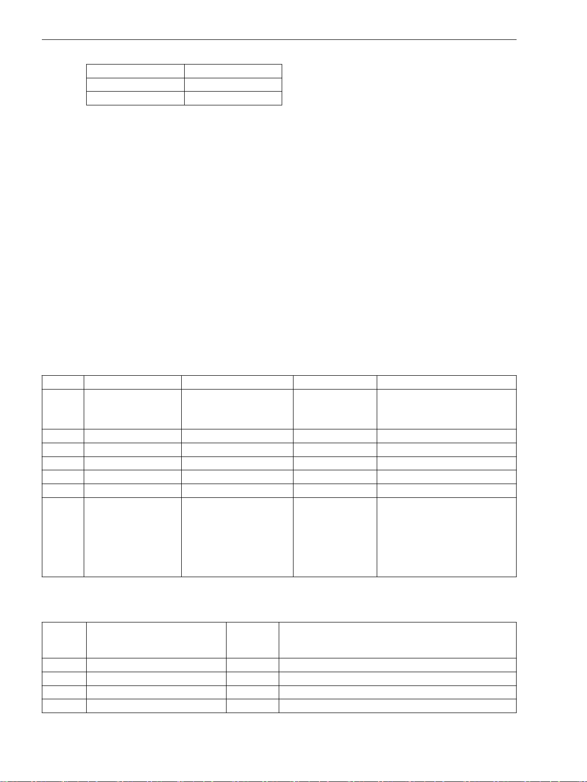
Functions
2.5 Overvoltage Protection
Voltage input Device connections
Ue Q9, Q10
Uf Q11, Q12
Typically a phase-to-phase voltage is connected, a phase-earth voltage may also be used however. In the latter
case the pickup thresholds must be matched accordingly
The setting of limit values and time delays of the overvoltage protection depends on the speed with which the
voltage regulator can regulate voltage variations. The protection must not intervene in the regulation process
of the faultlessly functioning voltage regulator. For this reason, the two-stage characteristic must always be
above the voltage time characteristic of the regulation procedure.
The long-time stage 4102 U> and 4103 T U> must intervene in case of steady-state overvoltages. It is set to
approximately 110 % to 115 % U4103 T U> and, depending on the regulator speed, to a range between 1.5 s
and 5 s.
In case of a full-load rejection of the generator, the voltage increases first in relation to the transient voltage.
Only then does the voltage regulator reduce it again to its nominal value. The U>> stage is set generally as a
short-time stage in a way that the transient procedure for a full-load rejection does not lead to a tripping.
Usual are e.g. for 4104 U>> about 130 % UN with a delay 4105 T U>> from zero to 0.5 s.
All setting times are additional time delays which do not include the operating times (measuring time, dropout
time) of the protective function.
The dropout ratio can be adapted at the address 4106 U> DOUT RATIO in small stages to the operating
conditions and used for highly precise signalizations (e.g. network infeed of wind power stations).
2.5.3
Addr.
4101 OVERVOLTAGE OFF
4102 U> 30.0 .. 200.0 V 115.0 V U> Pickup
4103 T U> 0.00 .. 60.00 sec 3.00 sec T U> Time Delay
4104 U>> 30.0 .. 200.0 V 130.0 V U>> Pickup
4105 T U>> 0.00 .. 60.00 sec 0.50 sec T U>> Time Delay
4106A U> DOUT RATIO 0.90 .. 0.99 0.95 U>, U>> Drop Out Ratio
4107 MEAS. INPUT Ua
2.5.4
Settings
Addresses which have an appended “A” can only be changed with DIGSI, under “Additional Settings”.
Parameter Setting Options Default Setting Comments
OFF Overvoltage Protection
ON
Block relay
Ua Used Measuring Input
Ub
Uc
Ud
Ue
Uf
Information List
No.
6513 >BLOCK O/V SP >BLOCK overvoltage protection
6516 >BLOCK U> SP >BLOCK overvoltage protection U>
6517 >BLOCK U>> SP >BLOCK overvoltage protection U>>
6565 Overvolt. OFF OUT Overvoltage protection switched OFF
86 SIPROTEC 4, 7VE61 and 7VE63, Manual
Information Type of
Information
Comments
C53000-G1176-C163-3, Edition 10.2017

Functions
2.5 Overvoltage Protection
No. Information Type of
Comments
Information
6566 Overvolt. BLK OUT Overvoltage protection is BLOCKED
6567 Overvolt. ACT OUT Overvoltage protection is ACTIVE
6568 U> picked up OUT Overvoltage U> picked up
6570 U> TRIP OUT Overvoltage U> TRIP
6571 U>> picked up OUT Overvoltage U>> picked up
6573 U>> TRIP OUT Overvoltage U>> TRIP
SIPROTEC 4, 7VE61 and 7VE63, Manual 87
C53000-G1176-C163-3, Edition 10.2017

Functions
2.6 Frequency Protection
2.6
2.6.1
Frequency Increase and Decrease
Frequency Protection
The frequency protection function detects abnormally high and low frequencies in the generator. If the
frequency lies outside the permissible range, appropriate switching actions are initiated, e.g. separating the
generator from the system.
A decrease in system frequency occurs when the system experiences an increase in real power demand, or
when a malfunction occurs with a generator governor or automatic generation control (AGC) system. The
frequency protection function is also used for generators which (for a certain time) operator to an island
network. This is due to the fact that the reverse power protection cannot operate in case of drive power
failure. The generator can be disconnected from the power system by means of the frequency decrease
protection.
An increase in system frequency occurs e.g. when large loads (island network) are removed from the
system, or on frequency control malfunction. This entails risk of self-excitation for generators feeding long
lines under no-load conditions.
Due to the use of filter functions, the frequency evaluation is free from harmonic influences and very accurate.
Functional Description
Frequency protection consists of the four frequency elements f1 to f4. To make protection flexible for
different power system conditions, theses stages can be used alternatively for frequency decrease or increase
separately, and can be independently set to perform different control functions. The setting decides on the
purpose of the individual frequency stage. For the f4 frequency stage, the user can specify independently of
the parameterized limit value if this stage shall function as decrease or increase stage. For this reason, it can
also be used for special applications, if, for example, frequency undershoot below the nominal frequency is to
be signaled.
Operating Range
The frequency can be determined as long as there is a sufficiently high voltage at the selected input. If the
measurement voltage drops below a settable value Umin, frequency protection is disabled because precise
frequency values can no longer be calculated from the signal.
Time Delays/Logic
Trippings can be delayed each using an added time stage. When the time delay expires, a trip signal is generated. After pickup dropout the tripping command is immediately reset, but not before the minimum command
duration has expired.
Each of the four frequency stages can be blocked individually by binary inputs.
The following figure shows the logic diagram for the frequency protection function.
88 SIPROTEC 4, 7VE61 and 7VE63, Manual
C53000-G1176-C163-3, Edition 10.2017

[logik-des-frequenzschutzes, 1, en_GB]
i
i
Figure 2-42 Logic diagram of the frequency protection
Functions
2.6 Frequency Protection
2.6.2
General
Pickup Values
Setting Notes
Frequency protection is only in effect and accessible if address 142 FREQUENCY Prot. is set to Enabled
during configuration of protective functions. If the function is not required Disabled is set. Address 4201
O/U FREQUENCY serves to switch the function ON or OFF or to block only the trip command (Block relay).
By configuring the rated frequency of the power system and the frequency threshold for each of the stages f1
PICKUP to f4 PICKUP in each case the function is established as either overvoltage or undervoltage protection. Set the pickup threshold lower than nominal frequency if the element is to be used for underfrequency
protection. Set the pickup threshold higher than nominal frequency if the element is to be used for overfrequency protection.
For the f4 frequency stage, the former applies only if the parameter 4214 THRESHOLD f4 is set to auto-
matic (default setting). If desired, this parameter can also be set to f> or f<, in which case the evaluation
direction (increase or decrease detection) can be specified independent of the parametrized f4 PICKUP
threshold.
If frequency protection is used for network decoupling and load shedding purposes, settings depend on the
actual network conditions. Normally a graded load shedding is strived for that takes into account priorities of
consumers or consumer groups.
Further application examples are covered under power stations. The frequency values to be set mainly
depend, also in these cases, on power system/power station operator specifications. In this context, frequency
decrease protection ensures the power station's own demand by disconnecting it from the power system on
time. The turbo regulator regulates the machine set to the nominal speed. Consequently, the station's own
demands can be continuously supplied at nominal frequency.
NOTE
If the threshold is set equal to the nominal frequency, the element is inactive.
SIPROTEC 4, 7VE61 and 7VE63, Manual 89
C53000-G1176-C163-3, Edition 10.2017

Functions
2.6 Frequency Protection
Under the assumption that apparent power is reduced to the same degree, turbine-driven generators can, as a
rule, be continuously operated down to 95 % of nominal frequency. However, for inductive consumers, the
frequency reduction not only means greater current consumption but also endangers stable operation. For
this reason, only a short-time frequency reduction down to about 48 Hz (for fN = 50 Hz) or 58 Hz (for fN = 60
Hz) is permissible.
A frequency increase can, for example, occur due to a load shedding or malfunction of the speed regulation
(e.g. in a stand-alone system). In this way, the frequency increase protection can, for example, be used as
overspeed protection.
Setting example:
Stage Cause Settings
f1 Disconnection from the network 48.00 Hz 58.00 Hz 1.00 s
f2 Shutdown 47.00 Hz 57.00 Hz 6.00 s
f3 Warning 49.50 Hz 59.50 Hz 20.00 s
f4 Alarm or tripping 52.00 Hz 62.00 Hz 10.00 s
Time Delays
The delay times T f1 to T f4 entered at addresses4204, 4207, 4210 and 4213) allow the frequency stages
to be graded. The set times are additional delay times not including the operating times (measuring time,
dropout time) of the protective function.
for fN = 50 Hz for fN = 60 Hz Delay
Minimum Voltage
Address 4215 Umin is used to set the minimum voltage which if undershot, frequency protection is blocked. A
value of approx. 65 % UN is recommended. The parameter value is based on phase-to-phase voltages. The
minimum voltage threshold can be deactivated by setting this address to 0.
Measurement Input
The parameter 4220 MEAS. INPUT establishes which of the 6 voltage inputs (Ua to Uf) of the device the
frequency measurement is to refer to. The following allocation applies between voltage input and device
connections:
Voltage input
Ua Q1, Q2
Ub Q3, Q4
Uc Q5, Q6
Ud Q7, Q8
Ue Q9, Q10
Uf Q11, Q12
2.6.3
Addr.
4201 O/U FREQUENCY OFF
4202 f1 PICKUP 40.00 .. 65.00 Hz 48.00 Hz f1 Pickup
4203 f1 PICKUP 40.00 .. 65.00 Hz 58.00 Hz f1 Pickup
4204 f1 PICKUP 12.00 .. 20.00 Hz 16.10 Hz f1 PICKUP
4205 T f1 0.00 .. 600.00 sec 1.00 sec T f1 Time Delay
4206 f2 PICKUP 40.00 .. 65.00 Hz 47.00 Hz f2 Pickup
Settings
Parameter Setting Options Default Setting Comments
Device connections
OFF Over / Under Frequency Protection
ON
Block relay
90 SIPROTEC 4, 7VE61 and 7VE63, Manual
C53000-G1176-C163-3, Edition 10.2017

Functions
2.6 Frequency Protection
Addr. Parameter Setting Options Default Setting Comments
4207 f2 PICKUP 40.00 .. 65.00 Hz 57.00 Hz f2 Pickup
4208 f2 PICKUP 12.00 .. 20.00 Hz 15.80 Hz f2 PICKUP
4209 T f2 0.00 .. 100.00 sec 6.00 sec T f2 Time Delay
4210 f3 PICKUP 40.00 .. 65.00 Hz 49.50 Hz f3 Pickup
4211 f3 PICKUP 40.00 .. 65.00 Hz 59.50 Hz f3 Pickup
4212 f3 PICKUP 12.00 .. 20.00 Hz 16.50 Hz f3 PICKUP
4213 T f3 0.00 .. 100.00 sec 20.00 sec T f3 Time Delay
4214 f4 PICKUP 40.00 .. 65.00 Hz 52.00 Hz f4 Pickup
4215 f4 PICKUP 40.00 .. 65.00 Hz 62.00 Hz f4 Pickup
4216 f4 PICKUP 12.00 .. 20.00 Hz 17.20 Hz f4 PICKUP
4217 T f4 0.00 .. 100.00 sec 10.00 sec T f4 Time Delay
4218 THRESHOLD f4 automatic
f>
f<
4219 Umin 10.0 .. 125.0 V 65.0 V Minimum Required Voltage for
4220 MEAS. INPUT Ua
Ub
Uc
Ud
Ue
Uf
automatic Handling of Threshold Stage f4
Operation
Ua Used Measuring Input
2.6.4
No.
5203 >BLOCK Freq. SP >BLOCK frequency protection
5206 >BLOCK f1 SP >BLOCK frequency protection stage f1
5207 >BLOCK f2 SP >BLOCK frequency protection stage f2
5208 >BLOCK f3 SP >BLOCK frequency protection stage f3
5209 >BLOCK f4 SP >BLOCK frequency protection stage f4
5211 Freq. OFF OUT Frequency protection is switched OFF
5212 Freq. BLOCKED OUT Frequency protection is BLOCKED
5213 Freq. ACTIVE OUT Frequency protection is ACTIVE
5215 Freq UnderV Blk OUT Frequency protection undervoltage Blk
5232 f1 picked up OUT Frequency protection: f1 picked up
5233 f2 picked up OUT Frequency protection: f2 picked up
5234 f3 picked up OUT Frequency protection: f3 picked up
5235 f4 picked up OUT Frequency protection: f4 picked up
5236 f1 TRIP OUT Frequency protection: f1 TRIP
5237 f2 TRIP OUT Frequency protection: f2 TRIP
5238 f3 TRIP OUT Frequency protection: f3 TRIP
5239 f4 TRIP OUT Frequency protection: f4 TRIP
Information List
Information Type of
Information
Comments
SIPROTEC 4, 7VE61 and 7VE63, Manual 91
C53000-G1176-C163-3, Edition 10.2017

Functions
2.7 Rate-of-frequency-change protection
2.7
2.7.1
Measuring Principle
Frequency Increase/ Decrease
Rate-of-frequency-change protection
With the rate-of-frequency-change protection, frequency changes can be quickly detected. This allows a
prompt response to frequency dips or frequency rises. A trip command can be issued even before the pickup
threshold of the frequency protection (see Section 2.6 Frequency Protection) is reached.
Frequency changes occur for instance when there is an imbalance between the generated and the required
active power. They call for control measures on the one hand and for switching actions on the other hand.
These can be unburdening measures, such as network decoupling, or disconnection of loads (load shedding).
The sooner these measures are taken after malfunctioning, the more effective they will be.
The two main applications for this protection function are thus network decoupling and load shedding.
Functional Description
From the voltage at the selected input, the frequency is determined once per cycle over a measuring window
of 3 cycles, and a mean value of two consecutive frequency measurements is formed. The frequency difference is then determined over a settable time interval (default setting 5 cycles). The ratio between frequency
difference and time difference corresponds to the frequency change; it can be positive or negative. The measurement is performed continuously (per cycle). Monitoring functions such as undervoltage monitoring, check
for phase angle jumps etc. to avoid overfunctioning.
The rate-of-frequency-change protection has four stages, from df1/dt to df4/dt. This allows the function to be
adapted variably to all power system conditions. The stages can be set to detect either frequency decreases (df/dt) or frequency increases (+df/dt). The -df/dt stage is only active for frequencies below the rated frequency,
or less if the underfrequency enabling is activated. Likewise, the df/dt stage is active for frequencies above the
rated frequency, or higher, if the overfrequency enabling is activated. The parameter setting decides for what
purpose the particular stage will be used.
To avoid a proliferation of setting parameters, the settable measuring window for the frequency difference
formation and the dropout difference are each valid for two stages.
Operating Ranges
The frequency can be determined as long as there is a sufficiently strong voltage at the selected input. If the
measurement voltage drops below a settable value U MIN, frequency protection is disabled because precise
frequency values can no longer be calculated from the signal.
Time Delays/Logic
Tripping can be delayed by a set time delay associated with each applied time stage. This is recommended for
monitoring of small gradients. When the time delay expires, a trip signal is generated. After pickup dropout
the tripping command is immediately reset, but not before the minimum command duration has expired.
Each of the four frequency change stages can be blocked individually by binary input. The undervoltage
blocking acts on all stages simultaneously.
92 SIPROTEC 4, 7VE61 and 7VE63, Manual
C53000-G1176-C163-3, Edition 10.2017

Functions
2.7 Rate-of-frequency-change protection
[logik-frequenzaenderungsschutzes, 1, en_GB]
Figure 2-43
2.7.2
Setting Notes
General
The rate-of-frequency-change protection is only effective and accessible if during the configuration address
145 df/dt Protect. has been set accordingly. 2 or 4 stages can be selected. The default setting is 2
df/dt stages.
At address 4501 df/dt Protect., the function ON or OFF can be set, or only the trip command can be
blocked (Block relay).
Pickup Values
The setting procedure is the same for all stages. In a first step, it must be determined whether the stage is to
monitor a frequency rise at f>fN or a frequency drop at f<fN. For stage 1, for instance, this setting is made at
address4502 df1/dt >/<. The pickup value is set as an absolute value at address 4503 STAGE df1/dt. The
setting of address 4502 informs the protection function of the applicable sign.
The pickup value depends on the application and is determined by power system conditions. In most cases, a
network analysis will be necessary. A sudden disconnection of loads leads to a surplus of active power. The
frequency rises and causes a positive frequency change. A failure of generators, on the other hand, leads to a
deficit of active power. The frequency drops and leads to a negative frequency change.
The following relations can be used as an example for estimation. They apply for the change rate at the beginning of a frequency change (approx. 1 second).
Logic diagram of the rate-of-frequency-change protection
SIPROTEC 4, 7VE61 and 7VE63, Manual 93
C53000-G1176-C163-3, Edition 10.2017

Functions
2.7 Rate-of-frequency-change protection
[df-dt-frequenzaenderung-020827-ho, 1, en_GB]
Where are:
f
N
ΔP Active power change
S
N
H Inertia constant
Typical values for H are:
for hydro-electric generators (salient-pole machines) H = 1.5 s bis 6 s
for turbine-driven generators (cylindrical-rotor machines) H = 2 s bis 10 s
for industrial turbine-generators H = 3 s bis 4 s
Example:
fN = 50 Hz
H = 3 s
Fall 1: ΔP/SN = 0.12
Fall 2: ΔP/SN = 0.48
Fall 1: df/dt = –1 Hz/s
Fall 2: df/dt = –4 Hz/s
The default settings are based on the above example. The four stages have been set symmetrically.
Nominal Frequency
ΔP = P
Consumption
– P
Generation
Nominal apparent power of the machines
Time Delays
The delay time should be set to zero wherever the protection function is supposed to respond very quickly.
This will be the case with high setting values. For the monitoring of small changes (< 1Hz/s), on the other
hand, a small delay time can be useful to avoid overfunctioning. The delay time for stage 1 is set at address
4504 T df1/dt, and the time set there is added to the protection operating time.
Release by the Frequency Protection
The parameter df1/dt & f1 (Address 4505) is used to set the release of the stage from a certain frequency
threshold on. For this the pertinent frequency stage of the frequency protection is queried. In the setting
example this is stage f1. To exclude coupling of the two functions, the parameter can be set to OFF (default
setting).
Advanced Parameters
The advanced parameters allow setting each for two stages (e.g. df1/dt and df2/dt) the dropout difference and
the measuring window. This setting can only be done with the DIGSI communication software.
Einstellungsänderungen sind erforderlich, wenn man z.B. eine große Rückfalldifferenz haben möchte. Sollen
sehr kleine Frequenzänderungen (<0,5 Hz/s) erfasst werden, so sollte das voreingestellte Messfenster verlängert werden. Damit verbessert man die Messgenauigkeit.
Setting value
Stage dfn/dt
df/dt HYSTERESE
(Adr. 4519, 4521)
0.1...0.5 Hz/s ≈ 0.05 25...10
0.5...1 Hz/s ≈ 0.1 10...5
1...5 Hz/s ≈ 0.2 10...5
5...10 Hz/s ≈ 0.5 5...1
dfx/dt M-WINDOW
(Adr. 4520, 4522)
94 SIPROTEC 4, 7VE61 and 7VE63, Manual
C53000-G1176-C163-3, Edition 10.2017

Minimum Voltage
Address 4518 U MIN is used to set the minimum voltage below which the frequency change protection will
be blocked. A value of approx. 65 % UN is recommended. The minimum voltage threshold can be deactivated
by setting this address to 0.
Functions
2.7 Rate-of-frequency-change protection
2.7.3
Addr. Parameter Setting Options Default Setting Comments
4501 df/dt Protect. OFF
4502 df1/dt >/< -df/dt<
4503 STAGE df1/dt 0.1 .. 10.0 Hz/s 1.0 Hz/s Pickup Value of df1/dt Stage
4504 STAGE df1/dt 0.1 .. 3.0 Hz/s 0.3 Hz/s Pickup Value of df1/dt Stage
4505 T df1/dt 0.00 .. 60.00 sec 0.50 sec Time Delay of df1/dt Stage
4506 df1/dt & f1 OFF
4507 df2/dt >/< -df/dt<
4508 STAGE df2/dt 0.1 .. 10.0 Hz/s 1.0 Hz/s Pickup Value of df2/dt Stage
4509 STAGE df2/dt 0.1 .. 3.0 Hz/s 0.3 Hz/s Pickup Value of df2/dt Stage
4510 T df2/dt 0.00 .. 60.00 sec 0.50 sec Time Delay of df2/dt Stage
4511 df2/dt & f2 OFF
4512 df3/dt >/< -df/dt<
4513 STAGE df3/dt 0.1 .. 10.0 Hz/s 4.0 Hz/s Pickup Value of df3/dt Stage
4514 STAGE df3/dt 0.1 .. 3.0 Hz/s 1.3 Hz/s Pickup Value of df3/dt Stage
4515 T df3/dt 0.00 .. 60.00 sec 0.00 sec Time Delay of df3/dt Stage
4516 df3/dt & f3 OFF
4517 df4/dt >/< -df/dt<
4518 STAGE df4/dt 0.1 .. 10.0 Hz/s 4.0 Hz/s Pickup Value of df4/dt Stage
4519 STAGE df4/dt 0.1 .. 3.0 Hz/s 1.3 Hz/s Pickup Value of df4/dt Stage
4520 T df4/dt 0.00 .. 60.00 sec 0.00 sec Time Delay of df4/dt Stage
4521 df4/dt & f4 OFF
4522 U MIN 10.0 .. 125.0 V 65.0 V Minimum Operating Voltage Umin
4523A df1/2 HYSTERES. 0.02 .. 0.99 Hz/s 0.10 Hz/s Reset Hysteresis for df1/dt & df2/dt
4524A df1/2 M-WINDOW 1 .. 25 Cycle 5 Cycle Measuring Window for df1/dt &
4525A df3/4 HYSTERES. 0.02 .. 0.99 Hz/s 0.40 Hz/s Reset Hysteresis for df3/dt & df4/dt
4526A df3/4 M-WINDOW 1 .. 25 Cycle 5 Cycle Measuring Window for df3/dt &
Settings
Addresses which have an appended “A” can only be changed with DIGSI, under “Additional Settings”.
OFF Rate-of-frequency-change protecON
Block relay
-df/dt< Mode of Threshold (df1/dt >/<)
+df/dt>
OFF AND logic with pickup of stage f1
ON
-df/dt< Mode of Threshold (df2/dt >/<)
+df/dt>
OFF AND logic with pickup of stage f2
ON
-df/dt< Mode of Threshold (df3/dt >/<)
+df/dt>
OFF AND logic with pickup of stage f3
ON
-df/dt< Mode of Threshold (df4/dt >/<)
+df/dt>
OFF AND logic with pickup of stage f4
ON
tion
df2/dt
df4/dt
SIPROTEC 4, 7VE61 and 7VE63, Manual 95
C53000-G1176-C163-3, Edition 10.2017

Functions
2.7 Rate-of-frequency-change protection
Addr. Parameter Setting Options Default Setting Comments
4527 MEAS. INPUT Ua
Ub
Uc
Ud
Ue
Uf
Ua Used Measuring Input
2.7.4
No. Information Type of
5503 >df/dt block SP >BLOCK Rate-of-frequency-change prot.
5504 >df1/dt block SP >BLOCK df1/dt stage
5505 >df2/dt block SP >BLOCK df2/dt stage
5506 >df3/dt block SP >BLOCK df3/dt stage
5507 >df4/dt block SP >BLOCK df4/dt stage
5511 df/dt OFF OUT df/dt is switched OFF
5512 df/dt BLOCKED OUT df/dt is BLOCKED
5513 df/dt ACTIVE OUT df/dt is ACTIVE
5515 df/dt U< block OUT df/dt is blocked by undervoltage
5516 df1/dt pickup OUT Stage df1/dt picked up
5517 df2/dt pickup OUT Stage df2/dt picked up
5518 df3/dt pickup OUT Stage df3/dt picked up
5519 df4/dt pickup OUT Stage df4/dt picked up
5520 df1/dt TRIP OUT Stage df1/dt TRIP
5521 df2/dt TRIP OUT Stage df2/dt TRIP
5522 df3/dt TRIP OUT Stage df3/dt TRIP
5523 df4/dt TRIP OUT Stage df4/dt TRIP
Information List
Comments
Information
96 SIPROTEC 4, 7VE61 and 7VE63, Manual
C53000-G1176-C163-3, Edition 10.2017

Functions
2.8 Jump of Voltage Vector
2.8
2.8.1
Frequency Behaviour on Load Shedding
Jump of Voltage Vector
Sometimes consumers with their own generating plant feed power directly into a network. The incoming
feeder line is usually the ownership boundary between the network utility and these consumers/producers. A
failure of the input feeder line, for example, due to a three-pole automatic reclosure, can result in a deviation
of the voltage or frequency at the feeding generator which is a function of the overall power balance. When
the incoming feeder line is switched on again after the dead time, asynchronous conditions may prevail that
cause damage to the generator or the gear train between generator and drive.
One way to identify an interruption of the incoming feeder is to monitor the phase angle in the voltage. If the
incoming feeder fails, the abrupt current interruption causes a phase angle jump in the voltage. This jump is
detected by means of a delta process. As soon as a preset threshold is exceeded, an opening command for the
generator or bus-tie coupler circuit-breaker is issued.
This means that the vector jump function is mainly used for network decoupling.
Functional Description
The following figure shows the evolution of the frequency when a load is disconnected from a generator.
Opening of the generator circuit breaker causes a phase angle jump that can be observed in the frequency
measurement as a frequency jump. The generator is accelerated in accordance with the power system conditions (see also Section 2.7 Rate-of-frequency-change protection “Rate-of-Frequency-Change Protection”).
[veraenderung-der-frequenz-nach-lastabschaltg-020904-ho, 1, en_GB]
Figure 2-44
Measuring Principle
The voltage vector is calculated from the voltage at the selected input, and the phase angle change is determined over a delta interval of 2 cycles. The presence of a phase angle jump indicates an abrupt change of
current flow. The basic principle is shown in the following figure. The diagram on the left shows the steady
state, and the diagram on the right the vector change following a load shedding. The vector jump is clearly
visible.
SIPROTEC 4, 7VE61 and 7VE63, Manual 97
C53000-G1176-C163-3, Edition 10.2017
Change of the Frequency after Disconnection of a Load (Fault recording with the SIPROTEC 4
device- the figure shows the deviation from the nominal frequency)

Functions
2.8 Jump of Voltage Vector
[spannungszeiger-nach-entlastung-020904-ho, 1, en_GB]
Figure 2-45 Voltage Vector Following Load Shedding
The function features a number of additional measures to avoid spurious tripping, such as:
Correction of steady-state deviations from rated frequency
•
Frequency operating range limited to fN ± 3 Hz
•
Logic
Minimum voltage for enabling
•
Blocking on voltage connection or disconnection
•
The logic is shown in the following figure. The phase angle comparison determines the angle difference, and
compares it with the set value. If this value is exceeded, the vector jump is stored in a RS flip-flop. Trippings
can be delayed by the associated time delay.
The stored pickup can be reset via a binary input, or automatically by a timer (address 4604 T RESET).
The vector jump function becomes ineffective on exiting the admissible frequency band. The same applies for
the voltage. In such a case the limiting parameters are U MIN and U MAX.
If the frequency or voltage range is not maintained, the logic generates a logical 1, and the reset input is
continuously active. The result of the vector jump measurement is suppressed. If, for instance, the voltage is
connected, and the frequency range is correct, the logical 1 changes to 0. The timer T BLOCK with reset delay
keeps the reset input active for a certain time, thus preventing a pickup caused by the vector jump function.
If a short-circuit causes the voltage to drop abruptly to a low value, the reset input is immediately activated to
block the function. The vector jump function is thus prevented from causing a trip.
98 SIPROTEC 4, 7VE61 and 7VE63, Manual
C53000-G1176-C163-3, Edition 10.2017

Functions
2.8 Jump of Voltage Vector
[ve6-logikdiagramm-vektorsprungerfassung-060603-kn, 1, en_GB]
Figure 2-46
2.8.2
Setting Notes
General
The vector jump protection is only effective and available if address 146 VECTOR JUMP is set to Enabled
during configuration.
Address 4601 VECTOR JUMP serves to switch the function ON or OFF or to block only the trip command
(Block relay).
Pickup Values
The value to be set for the vector jump (address 4602 DELTA PHI) depends on the feed and load conditions.
Abrupt active power changes cause a jump of the voltage vector. The value to be set must be established in
accordance with the particular power system. This can be done on the basis of the simplified equivalent circuit
of the diagram “Voltage Vector after a Load Shedding” in the Functional Description section, or using network
calculation software.
If a setting is too sensitive, the protection function is likely to perform a network decoupling every time loads
are connected or disconnected. Therefore the default setting is 10°.
The admissible voltage operating range can be set at addresses 4605 für U MIN and 4606 für U MAX. Setting
range limits are to some extent a matter of the utility's policy. The value for U MIN should be below the
admissible level of short voltage dips for which network decoupling is desired. The default setting is 80 % of
the nominal voltage. For U MAX the maximum admissible voltage must be selected. This will be in most cases
130 % of the nominal voltage
Logic Diagram of the Vector Jump Detection
Time Delays
The time delay T DELTA PHI (address 4603) should be left at zero, unless you wish to transmit the trip indication with a delay to a logic (CFC), or to leave enough time for an external blocking to take effect.
SIPROTEC 4, 7VE61 and 7VE63, Manual 99
C53000-G1176-C163-3, Edition 10.2017

Functions
2.8 Jump of Voltage Vector
After expiry of the timer T RESET (address 4604), the protection function is automatically reset. The reset
time depends on the decoupling policy. It must have expired before the circuit breaker is reclosed. Where the
automatic reset function is not used, the timer is set to ∞. The reset signal must come in this case from the
binary input (circuit breaker auxiliary contact).
The timer T BLOCK with reset delay (address 4607) helps to avoid overfunctioning when voltages are
connected or disconnected. Normally the default setting need not be changed. Any change can be performed
with the DIGSI communication software (advanced parameters). It must be kept in mind that T BLOCK should
always be set to more than the measuring window for vector jump measurement (2 cycles).
2.8.3
Addr. Parameter Setting Options Default Setting Comments
4601 VECTOR JUMP OFF
4602 DELTA PHI 2 .. 30 ° 10 ° Jump of Phasor DELTA PHI
4603 T DELTA PHI 0.00 .. 60.00 sec 0.00 sec T DELTA PHI Time Delay
4604 T RESET 0.10 .. 60.00 sec 5.00 sec Reset Time after Trip
4605A U MIN 10.0 .. 125.0 V 80.0 V Minimal Operation Voltage U MIN
4606A U MAX 10.0 .. 170.0 V 130.0 V Maximal Operation Voltage U
4607A T BLOCK 0.00 .. 60.00 sec 0.10 sec Time Delay of Blocking
4609 MEAS. INPUT Ua
Settings
Addresses which have an appended “A” can only be changed with DIGSI, under “Additional Settings”.
OFF Jump of Voltage Vector
ON
Block relay
MAX
Ua Used Measuring Input
Ub
Uc
Ud
Ue
Uf
2.8.4
No.
5581 >VEC JUMP block SP >BLOCK Vector Jump
5582 VEC JUMP OFF OUT Vector Jump is switched OFF
5583 VEC JMP BLOCKED OUT Vector Jump is BLOCKED
5584 VEC JUMP ACTIVE OUT Vector Jump is ACTIVE
5585 VEC JUMP Range OUT Vector Jump not in measurement range
5586 VEC JUMP pickup OUT Vector Jump picked up
5587 VEC JUMP TRIP OUT Vector Jump TRIP
100 SIPROTEC 4, 7VE61 and 7VE63, Manual
Information List
Information Type of
Information
Comments
C53000-G1176-C163-3, Edition 10.2017
 Loading...