

Siemens SIPROTEC 4 7UT6 Series Manual

Preface
Table of Contents
SIPROTEC 4
Differential Protection
7UT6x
V4.67
Manual
Introduction
Functions
Mounting and Commissioning
Technical Data
Ordering Information and Accessories
Terminal Assignments
Connection Examples
Current Transformer Requirements
Default Settings and Protocol-dependent
Functions
1
2
3
4
A
B
C
D
E
C53000-G1176-C230-5
Functions, Settings, Information
Literature
Glossary
Index
F

i
i
NOTE
For your own safety, observe the warnings and safety instructions contained in this document, if available.
Disclaimer of Liability
We have checked the text of this manual for conformity
with the hardware and software described. However, since
deviations cannot be ruled out entirely, we do not accept
liability for complete conformity or for any any errors or
omissions.
The information given in this document is reviewed regularly and any necessary corrections will be included in
subsequent editions. We appreciate any suggestions for
improvement.
We reserve the right to make technical improvements
without notice.
Document Version 4.04.00
Release date 09.2016
Copyright
Copyright© Siemens AG 2016. All rights reserved.
The reproduction, transmission or use of this document or
its contents is not permitted without express written
authority. Offenders will be liable for damages. All rights
reserved, particularly for the purposes of patent application
or trademark registration.
Registered Trademarks
SIPROTEC, SINAUT, SICAM and DIGSI are registered trademarks of SIEMENS AG. Other designations in this manual
might be trademarks whose use by third parties for their
own purposes would infringe the rights of the owner.

Preface
Purpose of this Manual
This manual describes the functions, operation, installation, and commissioning of devices 7UT6x. In particular, one will find:
Information regarding the configuration of the scope of the device and a description of the device func-
•
tions and settings → Chapter 2;
Instructions for Installation and Commissioning → Chapter 3;
•
Compilation of the Technical Data → Chapter 4;
•
As well as a compilation of the most significant data for advanced users → Appendix A.
•
General information with regard to design, configuration, and operation of SIPROTEC 4 devices are set out in
the SIPROTEC 4 System Description /1/ SIPROTEC 4 System Manual.
Target Audience
Protection-system engineers, commissioning engineers, persons entrusted with the setting, testing and maintenance of selective protection, automation and control equipment, and operating personnel in electrical
installations and power plants.
Applicability of this Manual
This manual applies to: SIPROTEC 4 Differential Protection 7UT6x; Firmware-Version V4.67.
Indication of Conformity
This product is UL-certified according to the Technical Data:
[ul-schutz-110602-kn, 1, --_--]
This product complies with the directive of the Council of the European Communities on the
approximation of the laws of the Member States relating to electromagnetic compatibility
(EMC Council Directive 2004/108/EEC) and concerning electrical equipment for use within
specified voltage limits (Low-voltage directive 2006/95 EEC).
This conformity is proved by tests conducted by Siemens AG in accordance with the directives
in agreement with the generic standards EN 61000-6-2 and EN 61000-6-4 for EMC directive
and standard EN 60255-5 (for low-voltage directive).
This device was designed and produced for industrial use.
The product conforms to the international standards of the IEC 60255 series and the German
standard VDE 0435.
SIPROTEC 4, 7UT6x, Manual
C53000-G1176-C230-5, Edition 09.2016
3

!
!
!
i
i
Preface
Additional Support
For questions about the SIPROTEC 4 system, please contact your Siemens sales partner.
Our Customer Support Center provides a 24-hour service.
Phone: +49 (180) 524-8437
Fax: +49 (180) 524-2471
e-mail: support.ic@siemens.com
Training Courses
Enquiries regarding individual training courses should be addressed to our Training Center:
Siemens AG
Siemens Power Academy TD
Humboldt Street 59 59
90459 Nuremberg
Phone: +49 (911) 433-7415
Fax: +49 (911) 433-5482
Internet: www.siemens.com/energy/power-academy
e-mail: poweracademy.ic-sg@siemens.com
Notes on Safety
This document is not a complete index of all safety measures required for operation of the equipment (module
or device). However, it comprises important information that must be followed for personal safety, as well as
to avoid material damage. Information is highlighted and illustrated as follows according to the degree of
danger:
DANGER
GEFAHR bedeutet, dass Tod oder schwere Verletzungen eintreten werden, wenn die angegebenen
Maßnahmen nicht getroffen werden.
Beachten Sie alle Hinweise, um Tod oder schwere Verletzungen zu vermeiden.
²
Danger indicates that death, severe personal injury or substantial material damage will result if proper
²
precautions are not taken.
WARNING
WARNING means that death or severe injury may result if the measures specified are not taken.
Comply with all instructions, in order to avoid death or severe injuries.
²
CAUTION
CAUTION means that medium-severe or slight injuries can occur if the specified measures are not taken.
Comply with all instructions, in order to avoid moderate or minor injuries.
²
NOTE
indicates information on the device, handling of the device, or the respective part of the instruction manual
which is important to be noted.
4 SIPROTEC 4, 7UT6x, Manual
C53000-G1176-C230-5, Edition 09.2016
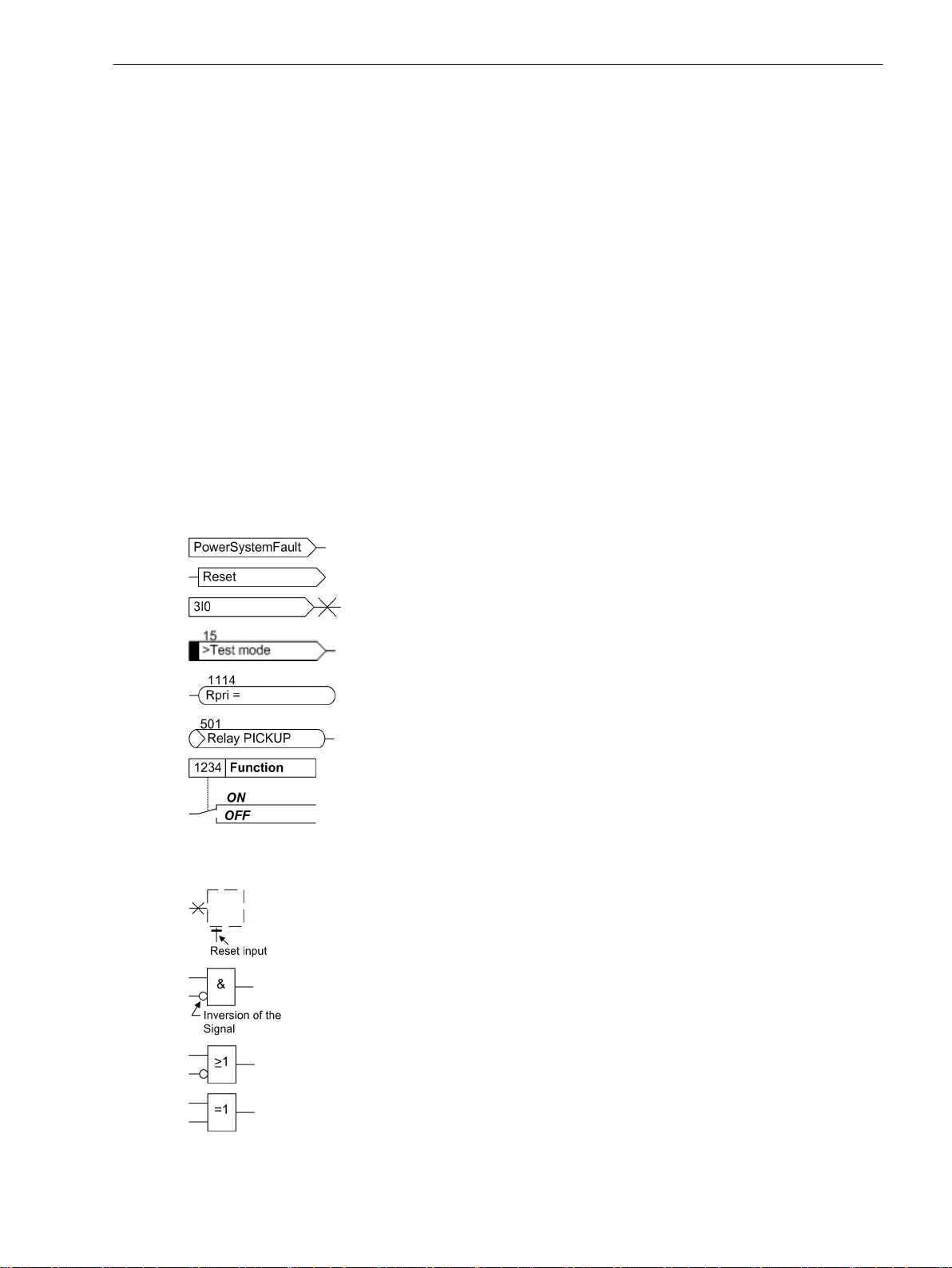
Typographic and Symbol Conventions
The following text formats are used when literal information from the device or to the device appear in the
text flow:
Parameter Names
Designators of configuration or function parameters which may appear word-for-word in the display of the
device or on the screen of a personal computer (with operation software DIGSI), are marked in bold letters in
monospace type style. The same applies to titles of menus.
1234A
Parameter addresses have the same character style as parameter names. Parameter addresses contain the
suffix A in the overview tables if the parameter can only be set in DIGSI via the option Display additional
settings.
Parameter Options
Possible settings of text parameters, which may appear word-for-word in the display of the device or on the
screen of a personal computer (with operation software DIGSI), are additionally written in italics. The same
applies to the options of the menus.
Indications
Designators for information, which may be output by the relay or required from other devices or from the
switch gear, are marked in a monospace type style in quotation marks.
Deviations may be permitted in drawings and tables when the type of designator can be obviously derived
from the illustration.
The following symbols are used in drawings:
Preface
Device-internal logical input signal
Device-internal logical output signal
Internal input signal of an analog quantity
External binary input signal with number (binary input,
input indication)
External binary output signal with number
(example of a value indication)
External binary output signal with number (device indication) used as
input signal
Example of a parameter switch designated FUNCTION with address
1234 and the possible settings Ein and Aus
Besides these, graphical symbols are used in accordance with IEC 60617-12 and IEC 60617-13 or similar.
Some of the most frequently used are listed below:
Analog input variable
AND-gate operation of input values
OR-gate operation of input values
Exclusive OR gate (antivalence): output is active, if only one of the
inputs is active
SIPROTEC 4, 7UT6x, Manual 5
C53000-G1176-C230-5, Edition 09.2016
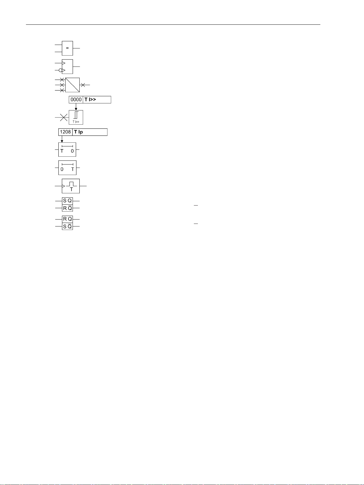
Preface
Coincidence gate: output is active, if both inputs are active or inactive
at the same time
Dynamic inputs (edge-triggered) above with positive, below with
negative edge
Formation of one analog output signal from a number of analog input
signals
Limit stage with setting address and parameter designator (name)
Timer (pickup delay T, example adjustable) with setting address and
parameter designator (name)
Timer (dropout delay T, example non-adjustable)
Dynamic triggered pulse timer T (monoflop)
Static memory (SR flipflop) with setting input (S), resetting input (R),
output (Q) and inverted output (Q), setting input dominant
Static memory (RS-flipflop) with setting input (S), resetting input (R),
output (Q) and inverted output (Q), resetting input dominant
6 SIPROTEC 4, 7UT6x, Manual
C53000-G1176-C230-5, Edition 09.2016

Table of Contents
Preface..........................................................................................................................................................3
1 Introduction................................................................................................................................................15
1.1 Overall Operation..............................................................................................................16
1.2 Application Scope............................................................................................................. 19
1.3 Characteristics.................................................................................................................. 21
2 Functions.................................................................................................................................................... 27
2.1 General.............................................................................................................................28
2.1.1 Device......................................................................................................................... 28
2.1.1.1 Setting Notes......................................................................................................... 28
2.1.1.2 Settings................................................................................................................. 29
2.1.1.3 Information List..................................................................................................... 29
2.1.2 EN100-Modul 1........................................................................................................... 30
2.1.2.1 Function Description.............................................................................................. 30
2.1.2.2 Setting Notes......................................................................................................... 30
2.1.2.3 Information List..................................................................................................... 30
2.1.3 Functional Scope......................................................................................................... 30
2.1.3.1 Setting Notes......................................................................................................... 30
2.1.3.2 Settings................................................................................................................. 37
2.1.4 Power System Data 1...................................................................................................40
2.1.4.1 Topology of the Protected Object........................................................................... 40
2.1.4.2 General Power System Data....................................................................................55
2.1.4.3 Assignment of Protection Functions to Measuring Locations / Sides.........................68
2.1.4.4 Circuit Breaker Data................................................................................................71
2.1.4.5 Settings................................................................................................................. 72
2.1.4.6 Information List..................................................................................................... 84
2.1.5 Setting Groups............................................................................................................ 85
2.1.5.1 Purpose of Setting Groups......................................................................................85
2.1.5.2 Setting Notes......................................................................................................... 85
2.1.5.3 Settings................................................................................................................. 85
2.1.5.4 Information List..................................................................................................... 85
2.1.6 Power System Data 2...................................................................................................86
2.1.6.1 Setting Notes......................................................................................................... 86
2.1.6.2 Settings................................................................................................................. 88
2.1.6.3 Information List..................................................................................................... 89
2.2 Differential Protection....................................................................................................... 92
2.2.1 Functional Description of the Differential Protection.....................................................92
2.2.2 Differential Protection for Transformers..................................................................... 101
2.2.3 Differential Protection for Generators, Motors, and Series Reactors.............................108
2.2.4 Differential Protection for Shunt Reactors...................................................................109
2.2.5 Differential Protection for Mini-Busbars and Short Lines..............................................110
2.2.6 Single-phase Differential Protection for Busbars......................................................... 111
SIPROTEC 4, 7UT6x, Manual 7
C53000-G1176-C230-5, Edition 09.2016

Table of Contents
2.2.7 Setting Notes.............................................................................................................115
2.2.8 Settings.....................................................................................................................121
2.2.9 Information List.........................................................................................................122
2.3 Restricted Earth Fault Protection......................................................................................125
2.3.1 Application Examples.................................................................................................125
2.3.2 Function Description..................................................................................................128
2.3.3 Setting Notes.............................................................................................................133
2.3.4 Settings.....................................................................................................................134
2.3.5 Information List.........................................................................................................134
2.4 Time Overcurrent Protection for Phase and Residual Currents...........................................136
2.4.1 General..................................................................................................................... 136
2.4.1.1 Definite Time, Instantaneous Overcurrent Protection............................................ 136
2.4.1.2 Inverse Time Overcurrent Protection.....................................................................140
2.4.1.3 Manual Close Command.......................................................................................143
2.4.1.4 Dynamic Cold Load Pickup....................................................................................143
2.4.1.5 Inrush Restraint....................................................................................................143
2.4.1.6 Fast Busbar Protection Using Reverse Interlocking.................................................145
2.4.2 Time Overcurrent Protection for Phase Currents......................................................... 146
2.4.2.1 Setting Notes....................................................................................................... 146
2.4.2.2 Settings............................................................................................................... 152
2.4.2.3 Information List................................................................................................... 154
2.4.3 Time Overcurrent Protection for Residual Current.......................................................155
2.4.3.1 Setting Notes....................................................................................................... 155
2.4.3.2 Settings............................................................................................................... 159
2.4.3.3 Information List................................................................................................... 160
2.5 Time Overcurrent Protection for Earth Current.................................................................161
2.5.1 General..................................................................................................................... 161
2.5.2 Definite Time, Instantaneous Overcurrent Protection..................................................161
2.5.3 Inverse Time Overcurrent Protection.......................................................................... 163
2.5.4 Manual Close Command............................................................................................ 165
2.5.5 Dynamic Cold Load Pickup......................................................................................... 165
2.5.6 Inrush Restraint......................................................................................................... 165
2.5.7 Setting Notes.............................................................................................................166
2.5.8 Settings.....................................................................................................................169
2.5.9 Information List.........................................................................................................171
2.6 Dynamic Cold Load Pickup for Time Overcurrent Protection............................................. 172
2.6.1 Functional Description...............................................................................................172
2.6.2 Setting Notes.............................................................................................................174
2.6.3 Settings.....................................................................................................................175
2.6.4 Information List.........................................................................................................175
2.7 Single-Phase Time Overcurrent Protection....................................................................... 177
2.7.1 Functional Description...............................................................................................177
2.7.2 High-impedance Differential Protection......................................................................178
2.7.3 Tank Leakage Protection............................................................................................180
2.7.4 Setting Notes.............................................................................................................181
2.7.5 Settings.....................................................................................................................185
2.7.6 Information List.........................................................................................................185
8 SIPROTEC 4, 7UT6x, Manual
C53000-G1176-C230-5, Edition 09.2016

Table of Contents
2.8 Unbalanced Load Protection............................................................................................187
2.8.1 Functional Description...............................................................................................187
2.8.2 Setting Notes.............................................................................................................193
2.8.3 Settings.....................................................................................................................198
2.8.4 Information List.........................................................................................................199
2.9 Thermal Overload Protection...........................................................................................200
2.9.1 General..................................................................................................................... 200
2.9.2 Overload Protection Using a Thermal Replica..............................................................200
2.9.3 Overload protection using a thermal replica with ambient temperature influence.......202
2.9.4 Hot-Spot Calculation and Determination of the Ageing Rate ...................................... 203
2.9.5 Setting Notes.............................................................................................................205
2.9.6 Settings.....................................................................................................................209
2.9.7 Information List.........................................................................................................210
2.10 RTD-Boxes for Overload Detection................................................................................... 211
2.10.1 Functional Description...............................................................................................211
2.10.2 Setting Notes.............................................................................................................211
2.10.3 Settings.....................................................................................................................211
2.10.4 Information List.........................................................................................................216
2.11 Overexcitation Protection................................................................................................218
2.11.1 Functional Description...............................................................................................218
2.11.2 Setting Notes.............................................................................................................219
2.11.3 Settings.....................................................................................................................222
2.11.4 Information List.........................................................................................................222
2.12 Reverse Power Protection................................................................................................ 224
2.12.1 Functional Description...............................................................................................224
2.12.2 Setting Notes.............................................................................................................225
2.12.3 Settings.....................................................................................................................227
2.12.4 Information List.........................................................................................................228
2.13 Forward Power Supervision............................................................................................. 229
2.13.1 Functional Description...............................................................................................229
2.13.2 Setting Notes.............................................................................................................230
2.13.3 Settings.....................................................................................................................232
2.13.4 Information List.........................................................................................................232
2.14 Undervoltage Protection................................................................................................. 233
2.14.1 Functional Description...............................................................................................233
2.14.2 Setting Notes.............................................................................................................234
2.14.3 Settings.....................................................................................................................235
2.14.4 Information List.........................................................................................................235
2.15 Overvoltage Protection....................................................................................................236
2.15.1 Functional Description...............................................................................................236
2.15.2 Setting Notes.............................................................................................................237
2.15.3 Settings.....................................................................................................................237
2.15.4 Information List.........................................................................................................238
2.16 Frequency Protection...................................................................................................... 239
2.16.1 Functional Description...............................................................................................239
2.16.2 Setting Notes.............................................................................................................240
SIPROTEC 4, 7UT6x, Manual 9
C53000-G1176-C230-5, Edition 09.2016

Table of Contents
2.16.3 Settings.....................................................................................................................242
2.16.4 Information List.........................................................................................................242
2.17 Circuit Breaker Failure Protection.....................................................................................244
2.17.1 Functional Description...............................................................................................244
2.17.2 Setting Notes.............................................................................................................247
2.17.3 Settings.....................................................................................................................250
2.17.4 Information List.........................................................................................................250
2.18 External Trip Commands................................................................................................. 251
2.18.1 Functional Description...............................................................................................251
2.18.2 Setting Notes.............................................................................................................252
2.18.3 Settings.....................................................................................................................252
2.18.4 Information List.........................................................................................................252
2.19 Monitoring Functions......................................................................................................254
2.19.1 Measurement Supervision......................................................................................... 254
2.19.1.1 Hardware Monitoring...........................................................................................254
2.19.1.2 Software Monitoring............................................................................................ 254
2.19.1.3 Monitoring of Measured Quantities...................................................................... 255
2.19.1.4 Setting Notes....................................................................................................... 257
2.19.1.5 Settings............................................................................................................... 257
2.19.1.6 Information List................................................................................................... 258
2.19.2 Trip Circuit Supervision.............................................................................................. 259
2.19.2.1 Functional Description......................................................................................... 259
2.19.2.2 Setting Notes....................................................................................................... 261
2.19.2.3 Settings............................................................................................................... 262
2.19.2.4 Information List................................................................................................... 262
2.19.3 Monitoring................................................................................................................ 262
2.19.3.1 Broken Wire Detection, Fuse Failure Monitoring....................................................262
2.19.3.2 Setting Notes....................................................................................................... 265
2.19.3.3 Settings............................................................................................................... 266
2.19.3.4 Information List................................................................................................... 266
2.19.4 Malfunction Responses of the Monitoring Functions.................................................. 268
2.19.4.1 Summary of the most important Monitoring Functions.........................................268
2.19.5 Parameterisation Error............................................................................................... 270
2.20 Function Control............................................................................................................. 271
2.20.1 Pickup Logic for the Entire Device.............................................................................. 271
2.20.2 Tripping Logic for the Entire Device............................................................................271
2.21 Disconnection of Measuring Locations.............................................................................273
2.21.1 Functional Description...............................................................................................273
2.21.2 Information List.........................................................................................................274
2.22 Auxiliary Functions..........................................................................................................276
2.22.1 Processing of Messages............................................................................................. 276
2.22.1.1 General................................................................................................................276
2.22.1.2 Operational Annunciations (Buffer: Event Log)..................................................... 277
2.22.1.3 Fault Annunciations (Buffer: Trip Log).................................................................. 277
2.22.1.4 Spontaneous Annunciations.................................................................................278
2.22.1.5 General Interrogation...........................................................................................278
2.22.1.6 Switching Statistics.............................................................................................. 278
2.22.2 Measurement............................................................................................................278
2.22.2.1 Display and Transmission of Measured Valuables..................................................278
2.22.2.2 Settings............................................................................................................... 282
2.22.2.3 Information List................................................................................................... 282
10 SIPROTEC 4, 7UT6x, Manual
C53000-G1176-C230-5, Edition 09.2016

Table of Contents
2.22.3 Thermal Measurement...............................................................................................285
2.22.3.1 Functional Description......................................................................................... 285
2.22.3.2 Information List................................................................................................... 286
2.22.4 Differential and Restraining Measured Values.............................................................287
2.22.4.1 Functional Description......................................................................................... 287
2.22.4.2 Information List................................................................................................... 287
2.22.5 Set Points for Measured Values.................................................................................. 288
2.22.5.1 User Defined Set-Points........................................................................................288
2.22.6 Energy Metering........................................................................................................288
2.22.6.1 Functional Description......................................................................................... 288
2.22.6.2 Information List................................................................................................... 289
2.22.7 Flexible Function....................................................................................................... 289
2.22.7.1 Functional Description......................................................................................... 289
2.22.7.2 Setting Notes....................................................................................................... 290
2.22.7.3 Settings............................................................................................................... 294
2.22.7.4 Information List................................................................................................... 297
2.22.8 Oscillographic Fault Recording...................................................................................298
2.22.8.1 Functional Description......................................................................................... 298
2.22.8.2 Setting Notes....................................................................................................... 298
2.22.8.3 Settings............................................................................................................... 299
2.22.8.4 Information List................................................................................................... 299
2.22.9 Commissioning Aids.................................................................................................. 299
2.22.9.1 Web-Monitor........................................................................................................299
2.23 Average Values, Minimum and Maximum Values.............................................................301
2.23.1 Demand Measurement Setup.....................................................................................301
2.23.1.1 Setting Notes....................................................................................................... 301
2.23.1.2 Settings............................................................................................................... 302
2.23.2 Min/Max Measurement Setup.................................................................................... 302
2.23.2.1 Setting Notes....................................................................................................... 302
2.23.2.2 Settings............................................................................................................... 302
2.23.2.3 Information List................................................................................................... 302
2.24 Command Processing......................................................................................................303
2.24.1 Control Authorization................................................................................................ 303
2.24.1.1 Type of Commands.............................................................................................. 303
2.24.1.2 Sequence in the Command Path...........................................................................303
2.24.1.3 Interlocking......................................................................................................... 304
2.24.1.4 Recording and Acknowledgement of Commands.................................................. 307
2.24.1.5 Information List................................................................................................... 307
3 Mounting and Commissioning................................................................................................................. 309
3.1 Mounting and Connections............................................................................................. 310
3.1.1 Configuration Information......................................................................................... 310
3.1.2 Hardware Modifications.............................................................................................314
3.1.2.1 General................................................................................................................314
3.1.2.2 Disassembly.........................................................................................................316
3.1.2.3 Switching Elements on Printed Circuit Boards....................................................... 320
3.1.2.4 Interface Modules................................................................................................ 336
3.1.2.5 Reassembly..........................................................................................................342
3.1.3 Mounting.................................................................................................................. 343
3.1.3.1 Panel Flush Mounting...........................................................................................343
3.1.3.2 Rack and Cubicle Mounting.................................................................................. 344
3.1.3.3 Panel Surface Mounting....................................................................................... 347
3.1.3.4 Removing the Transport Protection.......................................................................348
SIPROTEC 4, 7UT6x, Manual 11
C53000-G1176-C230-5, Edition 09.2016

Table of Contents
3.2 Checking Connections.....................................................................................................349
3.2.1 Checking Data Connections of Interfaces................................................................... 349
3.2.2 Checking the System Connections............................................................................. 351
3.3 Commissioning............................................................................................................... 354
3.3.1 Test Mode / Transmission Block..................................................................................355
3.3.2 Test Time Synchronisation Interface...........................................................................355
3.3.3 Testing the System Interface......................................................................................355
3.3.4 Checking the switching states of the binary Inputs/Outputs........................................357
3.3.5 Checking the Setting Consistency.............................................................................. 359
3.3.6 Secondary Tests.........................................................................................................365
3.3.7 Circuit Breaker Failure Protection Tests.......................................................................370
3.3.8 Symmetrical, Primary Current Tests on the Protected Object.......................................372
3.3.9 Zero Sequence Current Tests on the Protected Object.................................................378
3.3.10 Current Tests for Busbar Protection............................................................................ 383
3.3.11 Testing of the Non-Assigned 1-Phase Current Inputs.................................................. 385
3.3.12 Checking the Voltage Connections and Polarity Check................................................386
3.3.13 Testing User-defined Functions..................................................................................390
3.3.14 Stability Check and Triggering Oscillographic Recordings............................................391
3.4 Final Preparation of the Device........................................................................................393
4 Technical Data.......................................................................................................................................... 395
4.1 General...........................................................................................................................396
4.1.1 Analogue Inputs........................................................................................................ 396
4.1.2 Auxiliary Voltage....................................................................................................... 396
4.1.3 Binary Inputs and Outputs .........................................................................................397
4.1.4 Frequency Measurement via the Positive Phase-sequence Voltage U1.........................398
4.1.5 Communications Interfaces....................................................................................... 399
4.1.6 Electrical Tests...........................................................................................................403
4.1.7 Mechanical Tests....................................................................................................... 405
4.1.8 Climatic Stress Test....................................................................................................405
4.1.9 Service Conditions..................................................................................................... 406
4.1.10 Construction .............................................................................................................406
4.2 Differential Protection..................................................................................................... 408
4.3 Restricted Earth Fault Protection......................................................................................414
4.4 Time Overcurrent Protection for Residual Current............................................................ 416
4.5 Time Overcurrent Protection for Earth Current.................................................................428
4.6 Dynamic Cold Load Pickup for Time Overcurrent Protection............................................. 430
4.7 Single-Phase Time Overcurrent Protection....................................................................... 431
4.8 Unbalanced Load Protection............................................................................................432
4.9 Thermal Overload Protection...........................................................................................440
4.10 RTD-Boxes for Overload Detection................................................................................... 443
4.11 Overexcitation Protection................................................................................................444
4.12 Reverse Power Protection................................................................................................ 446
4.13 Forward Power Supervision............................................................................................. 447
4.14 Undervoltage Protection................................................................................................. 449
4.15 Overvoltage Protection....................................................................................................450
12 SIPROTEC 4, 7UT6x, Manual
C53000-G1176-C230-5, Edition 09.2016

Table of Contents
4.16 Frequency Protection...................................................................................................... 451
4.17 Circuit Breaker Failure Protection.....................................................................................453
4.18 External Trip Commands................................................................................................. 454
4.19 Monitoring Functions......................................................................................................455
4.20 User-defined Functions (CFC).......................................................................................... 456
4.21 Flexible Function.............................................................................................................459
4.22 Additional Functions....................................................................................................... 461
4.23 Dimensions.....................................................................................................................465
4.23.1
4.23.2
4.23.3
4.23.4
4.23.5
4.23.6
Panel surface mounting (housing size 1/3).................................................................. 465
Panel Surface Mounting (housing Size 1/2)..................................................................465
Panel Surface Mounting (housing Size 1/1)..................................................................466
Panel flush mounting or cubicle mounting (housing size 1/3)...................................... 467
Panel flush mounting or cubicle mounting (housing size 1/2)...................................... 468
Panel flush mounting or cubicle mounting (housing size 1/1)...................................... 469
4.23.7 RTD box.....................................................................................................................470
A Ordering Information and Accessories.....................................................................................................471
A.1 Differential Protection 7UT612 for 2 Measuring Locations................................................472
A.2 Differential Protection 7UT613 for 3 Measuring Locations................................................474
A.3 1.1.3 Differential Protection 7UT633 and 7UT635 for 3 to 5 measuring locations.............477
A.4 Accessories.....................................................................................................................480
B Terminal Assignments..............................................................................................................................483
B.1 Panel Flush and Cubicle Mounting...................................................................................484
B.2 Panel Surface Mounting.................................................................................................. 494
C Connection Examples............................................................................................................................... 505
C.1 Current Transformer Connection Examples......................................................................506
C.2 Voltage Transformer Connection Examples......................................................................519
C.3 Assignment of Protection Functions to Protected Objects.................................................521
D Current Transformer Requirements......................................................................................................... 523
D.1 General Requirements.....................................................................................................524
E Default Settings and Protocol-dependent Functions............................................................................... 529
E.1 Default Settings LEDs...................................................................................................... 530
E.2 Default Settings Binary Inputs......................................................................................... 531
E.3 Default Settings Binary Outputs.......................................................................................532
E.4 Default Settings Function Keys........................................................................................ 533
E.5 Default Display................................................................................................................534
E.6 Pre-defined CFC Charts....................................................................................................536
E.7 Protocol-dependent Functions.........................................................................................537
F Functions, Settings, Information..............................................................................................................539
F.1 Functional Scope............................................................................................................ 540
F.2 Settings.......................................................................................................................... 543
F.3 Information List.............................................................................................................. 587
SIPROTEC 4, 7UT6x, Manual 13
C53000-G1176-C230-5, Edition 09.2016

Table of Contents
F.4 Group Alarms..................................................................................................................654
F.5 Measured Values.............................................................................................................656
Literature.................................................................................................................................................. 665
Glossary.................................................................................................................................................... 667
Index.........................................................................................................................................................677
14 SIPROTEC 4, 7UT6x, Manual
C53000-G1176-C230-5, Edition 09.2016

1
Introduction
The device family SIPROTEC 7UT6x devices is introduced in this section. An overview of the devices is
presented in their application, characteristics, and scope of functions.
1.1 Overall Operation 16
1.2 Application Scope 19
1.3 Characteristics 21
SIPROTEC 4, 7UT6x, Manual 15
C53000-G1176-C230-5, Edition 09.2016
Introduction
1.1 Overall Operation
1.1
Overall Operation
The digital differential protection devices SIPROTEC 4 7UT6x are equipped with a powerful microprocessor
system. This provides fully numerical processing of all functions in the device, from the acquisition of the
measured values up to the output of commands to the circuit breakers
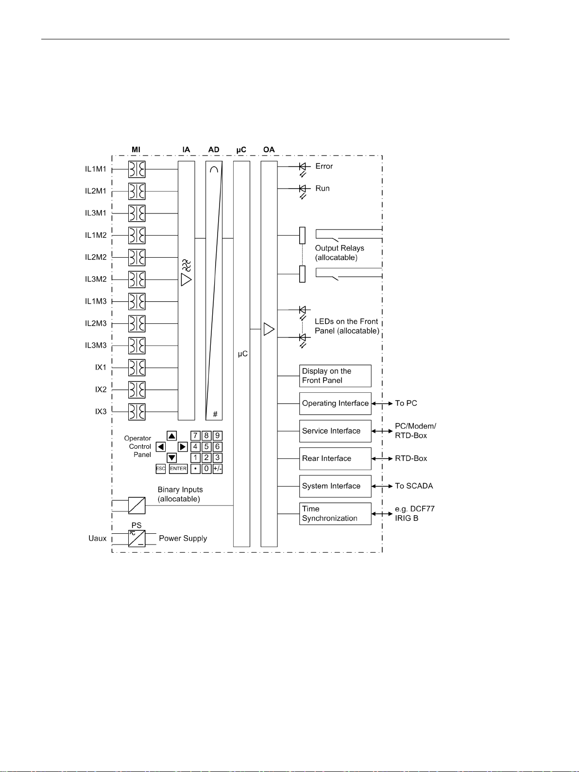
[hardwarestruktur-270203-st, 1, en_GB]
Figure 1-1
Analogue Inputs
The measuring inputs MI transform the currents and voltages derived from the instrument transformers and
match them to the internal signal levels for processing in the device. Depending on the version, the device
features between 8 current inputs (7UT612), 12 current inputs (7UT613/7UT633) and 16 current inputs
(7UT635). Three current inputs are provided for the input of the phase currents at each end of the protected
zone (= measuring points) of a 3-phase protected object; depending on the version, one or more further
single-phase measuring inputs (= additional inputs) may be used for any desired current, e.g. the earth current
measured between the starpoint of a transformer winding and earth, or other single-phase measuring
16 SIPROTEC 4, 7UT6x, Manual
Hardware structure of the digital differential current protection relay 7UT6x — Example of a
7UT613 for a three-winding transformer with measuring locations M1, M2 and M3, with 3
auxiliary 1-phase inputs X1, X2 and X3
C53000-G1176-C230-5, Edition 09.2016

currents. One or two additional inputs can be designed for highly sensitive current detection. thus allowing,
for example, the detection of small tank leakage currents of power transformers or reactors, or — with an
external series resistor — processing of a voltage (e.g. for high-impedance unit protection).
The versions 7UT613 and 7UT633 are available with 4 voltage inputs. 3 of these inputs can be connected to
the phase-to-earth voltages. Another voltage input can be used for a single-phase voltage, such as a displacement voltage or any other voltage. In principle, the differential protection is designed such that it can operate
without measured voltages. However, the integrated voltage protection functions use the measuring voltage
inputs, as for example the overexcitation protection, to calculate the induction in transformers or shunt reactors. In addition, the measuring voltages and the quantities derived from them (induction, power, power
factor) can be displayed, annunciated and/or monitored by the device if the voltages are connected.
The analogue signals are then routed to the input amplifier group IA.
The input amplifier group IA provides high-resistance termination for the analogue input quantities and
contains filters that are optimised for measured value processing with regard to bandwidth and processing
speed.
The analogue-to-digital (AD) stage consists of a multiplexor, an analogue-to-digital (A/D) converter and
memory components for the transmission of digital signals to the microcomputer system.
Microcomputer system
In addition to the control of the measured values, the actual protection and control functions are processed in
the μC microcomputer system. In particular, the following is included:
filtering and conditioning of measured signals
•
continuous monitoring of measured signals
•
monitoring of the pickup conditions of the individual protective functions
•
Conditioning of the measured signals: i.e. conversion of currents according to the connection group of
•
the protected transformer (when used for transformer differential protection) and matching of the
current amplitudes
Introduction
1.1 Overall Operation
formation of the differential and restraint quantities
•
Frequency analysis of the phase currents and restraint quantities
•
calculation of the RMS values of the currents for overload detection and adjustment of the temperature
•
rise of the protected object
retrieval of threshold values and time sequences
•
processing of signals for the logic functions
•
processing User-defined Logic Functions
•
reaching trip command decisions
•
check of control commands and output to switching devices
•
storage of indications, fault data and fault values for fault analysis purposes
•
calculation and display/annunciation of measured values and the quantities derived from them
•
management of the operating system and its functions, e.g. data storage, real-time clock, communica-
•
tion, interfaces, etc.
The information is provided via output amplifier OA.
Binary Inputs and Outputs
Binary inputs and outputs from and to the computer system are routed via the I/O modules (inputs and
outputs). The computer system obtains the information from the system (e.g remote resetting) or from other
devices (e.g. blocking commands). These outputs include, in particular, trip commands to switchgear and
signals for remote annunciation of important events and conditions.
SIPROTEC 4, 7UT6x, Manual 17
C53000-G1176-C230-5, Edition 09.2016

Introduction
1.1 Overall Operation
Front Elements
Devices with operator panel have light emitting diodes (LEDs) and a display screen (LCD) on the front panel to
provide information such as measured values, messages related to events or faults, status, and functional
status.
Integrated control and numeric keys in conjunction with the LCD facilitate local interaction with the 7UT6. All
information of the device can be accessed using the integrated control and numeric keys. The information
includes protective and control settings, operating and fault messages, and measured values.
In addition, control of circuit breakers and other equipment is possible from the 7UT6 front panel.
The versions 7UT612 and 7UT613 have a 4-line LC display in front, whereas the versions 7UT633 and 7UT635
have a graphic display. The latter devices also have integrated keyswitches and control buttons for on-site
control.
Serial interfaces
Via the serial operator interface in the front panel, communication with a personal computer using the operating program DIGSI is possible. This facilitates a comfortable handling of all device functions.
A serial service interface can likewise make communication via PC with the device possible by using DIGSI.
This port is especially well suited for the fixed wiring of the devices to the PC or operation via a modem.
All data can be transferred to a central control or monitoring system via the serial system port. This interface
may be provided with various protocols and physical transmission schemes to suit the particular application.
A further interface is provided for the time synchronization of the internal clock via external synchronization
sources.
Further communication protocols can be realized via additional interface modules.
The service port, or an optional additional interface, can also be used to connect a RTD-Box (= resistance
temperature detector) for entering external temperatures (e.g. for overload protection). The additional interface is available for all 7UT6x devices.
Power Supply
The functional units described are supplied by a power supply PS with the necessary power in the different
voltage levels. Transient dips of the supply voltage, which may occur during short-circuit in the power supply
system, are bridged by a capacitor (see also Technical Data).
18 SIPROTEC 4, 7UT6x, Manual
C53000-G1176-C230-5, Edition 09.2016

Introduction
1.2 Application Scope
1.2
Application Scope
The numerical differential protection SIPROTEC 4 7UT6x is a selective short-circuit protection for transformers
of all voltage levels, for rotating machines, for series and shunt reactors, or for short lines and mini-busbars
with 2 to 5 feeders (depending on the version). Being a single-phase device, it can also be used for small
busbars with up to 7, 9 or 12 feeders (depending on the version). The individual application can be configured, which ensures optimum matching to the protected object.
The devices 7UT613, 7UT633 and 7UT635 can also be run with 2-phase connection for 16.7 Hz applications.
A major advantage of the differential protection principle is the instantaneous tripping in the event of a short-
circuit at any point within the entire protected zone. The current transformers limit the protected zone at the
ends towards the network. This rigid limit is the reason why the differential protection scheme shows such an
ideal selectivity.
For use as transformer protection, the device is normally connected to the current transformer sets which limit
the power transformer windings against the remainder of the system. The phase displacement and the interlinkage of the currents due to the winding connection of the transformer are matched in the device by calculation algorithms. The earthing conditions of the starpoint(s) can be adapted to the user's requirements and are
automatically considered in the matching algorithms. Also, the currents from multiple measuring points on
one side of the protected object can be combined.
For use as generator or motor protection, the device compares the currents in the starpoint leads of the
machine and at its terminals. Similar applies for series reactors.
Short lines or mini-busbars with 2 to 5 ends or feeders (depending on the version) can be protected as well.
Short means that the current transformer connections from the CTs to the device cause no impermissible
burden for the current transformers.
For transformers, generators, motors, or shunt reactors with earthed starpoint, the current between the starpoint and earth can be measured and used for highly sensitive earth fault protection.
The 7, 9 or 12 standard current inputs (depending on the version) of the device allow for a single-phase
protection for busbars with up to 7, 9 or 12 feeders. One 7UT6x is used per phase in this case. Alternatively,
(external) summation transformers can be installed in order to allow a busbar protection for up to 7, 9 or 12
feeders with one single 7UT6x relay.
Where not all analog measuring inputs are needed for the measured values of the protected object, the
remaining inputs can be used for other, independent measurement or protection tasks. If a 7UT635 (with 5
threephase measuring inputs) is used, for instance, on a three-winding transformer, the two remaining measuring inputs c
One or two additional current inputs designed for very high sensitivity are also available. They may be used
e.g. for detection of small leakage currents between the tank of transformers or reactors an earth, thus recognising even high-resistance faults. High-resistance voltage measurement is also possible using an external
series resistor.
For transformers (including auto-transformers), generators, and shunt reactors, a high-impedance unit protection system can be formed using high-impedance earth fault protection. In this case, the currents of all current
transformers (of equal design) at the ends of the protected zone feed a common (external) high-ohmic
resistor. The current of this resistor is measured using one of the high-sensitive current inputs of the device.
The device provides backup time overcurrent protection functions for all types of protected objects. The functions can be enabled for any side or measuring location.
A thermal overload protection function is available for any type of machine. The functions can be enabled for
any side. External detectors account for the coolant temperature (by means of an external RTD-box). This
allows to calculate and output the hot-spot temperature and the relative ageing rate.
An unbalanced load protection function is provided for the detection of unsymmetrical currents. Phase failures
and negative sequence currents, which are especially dangerous for rotating machines, can thus be detected.
Performance functions allow devices with voltage measuring inputs to implement a reverse power protection
or monitor the forward power supply(in the power station sector). In the system they can be used for network
decoupling. Power results and their components can be emitted as measured values.
The versions with voltage inputs are provided with an integrated overexcitation protection for the detection of
excessive induction states in shunt reactions (transformers, shunt reactors). This protection function monitors
the ratio U/f, which is proportional to the induction B in the iron core. An imminent iron core saturation, which
SIPROTEC 4, 7UT6x, Manual 19
C53000-G1176-C230-5, Edition 09.2016

Introduction
1.2 Application Scope
can occur especially in power stations following (full) load shutdown and/or frequency reduction, is thus
detected.
An undervoltage and overvoltage protection is to be integrated into devices with voltage measuring inputs. A
4-stage frequency protection monitors the frequency from the measured voltages.
A version for two-phase application is available for traction supply (transformers or generators) which provides
all functions suited for this application (differential protection, restricted earth fault protection, overcurrent
protection, overload protection).
A circuit breaker failure protection checks the reaction of one circuit breaker after a trip command.
Further-reaching protection, monitoring and measuring functions can be configured individually by means of
flexible functions. For up to 12 such functions, you determine yourself which measuring quantities to process
and how to process them, and also which reactions the device is to trigger when settable limit values are
overor undershot. Thus you can, for instance, create further time overcurrent protection functions and process
voltages, powers or symmetrical components.
One can configure the calculation of minimum, maximum and/or average values and/or minimum, maximum
of the average values of up to 20 selectable measured quantities, thus receiving one's own statistical data.
For the devices 7UT613, 7UT633 and 7UT635, you can optionally create some protective functions several
times and assign them flexibly to the measuring locations of the protected object. Examples: Time overcurrent
protection, breaker failure protection, and the like (see Technical Data).
20 SIPROTEC 4, 7UT6x, Manual
C53000-G1176-C230-5, Edition 09.2016

Introduction
1.3 Characteristics
1.3
General Features
Transformer Differential Protection
Characteristics
Powerful 32-bit microprocessor system
•
Complete digital measured value processing and control, from the sampling and digitalization of the
•
analogue input quantities to the initiation of outputs for tripping or closing circuit breakers
Complete galvanic and reliable separation between the internal processing circuits of the device and the
•
external measurement, control, and power supply circuits because of the design of the analog input
transducers, binary input and output modules, and the DC/DC or AC/DC converters
Suitable for power transformers, generator, motors, reactors, or smaller busbar arrangements, as well as
•
for multi-terminal lines and multi-winding transformers
Easy device operation through an integrated operator panel or by means of a connected personal
•
computer running DIGSI.
Current restraint tripping characteristic
•
Restraint feature against high inrush currents with 2nd harmonic
•
Restraint feature against high inrush currents with Current waveform analysis CWA
•
Restraint feature against transient and steady-state fault currents caused e.g. by overexcitation of trans-
•
formers, using a further harmonic (3rd or 5th harmonic)
Insensitivity to DC components and current transformer saturation
•
High level of stability even with different degrees of current transformer saturation
•
High-speed instantaneous trip in case of high-current transformer faults
•
Independent of the conditioning of the starpoint(s) of the power transformer
•
Adjustable to the conditioning of the starpoint(s) of the power transformer
•
Increased earth-fault sensitivity during detection of the ground current of an earthed transformer
•
winding
Integrated matching of the transformer connection group
•
Integrated matching of the transformation ratio including different rated currents of the transformer
•
windings.
Differential Protection for Generators and Motors
Current restraint tripping characteristic
•
High sensitivity
•
Short tripping time
•
Insensitivity to DC components and current transformer saturation
•
High level of stability even with different degrees of current transformer saturation
•
Independent of the conditioning of the starpoint
•
Differential Protection for Mini-Busbars and Short Lines
Tripping characteristic with current restraint
•
Short tripping time
•
Insensitivity to DC components and current transformer saturation
•
SIPROTEC 4, 7UT6x, Manual 21
C53000-G1176-C230-5, Edition 09.2016

Introduction
1.3 Characteristics
High level of stability even with different degrees of current transformer saturation
•
Monitoring of the current connections with operation currents
•
Busbar Protection
Single-phase differential protection for a busbar with up to 7 or 9 or 12 feeders (depending on the
•
variant ordered)
Either one relay per phase or one relay connected via interposed summation current transformers
•
Tripping characteristic with current restraint
•
Short tripping time
•
Insensitivity to DC components and current transformer saturation
•
High level of stability even with different degrees of current transformer saturation
•
Monitoring of the current connections with operation currents.
•
Earth Fault Differential Protection
Earth fault protection for earthed transformer windings, generators, motors, shunt reactors, or starpoint
•
formers
Short command duration
•
High sensitivity for earth faults within the protected zone
•
High stability against external earth faults using the magnitude and phase relationship of through-
•
flowing earth current
2 restricted earth fault protection functions possible (only 7UT613/63x)
•
High-impedance Differential Protection
Highly sensitive fault current detection using a common (external) burden resistor
•
Short tripping time
•
Insensitive against DC components and current transformer saturation
•
High stability with optimum matching
•
Suitable for earth fault detection on earthed generators, motors, shunt reactors, and transformers,
•
including auto-transformers, with or without earthed starpoint
Suitable for any voltage measurement (via the resistor current) for application of high-impedance unit
•
protection
Tank Leakage Protection
For transformers or reactors the tank of which is installed isolated or with high resistance
•
Monitoring of the current flowing between the tank and ground
•
Can be connected via a „normal“ current input of the device or the special highly sensitive current input
•
(3 mA smallest setting)
Earth Fault Differential Protection
Earth fault protection for earthed transformer windings, generators, motors, shunt reactors, or starpoint
•
formers
Short command duration
•
High sensitivity for earth faults within the protected zone
•
22 SIPROTEC 4, 7UT6x, Manual
C53000-G1176-C230-5, Edition 09.2016

High stability against external earth faults using the magnitude and phase relationship of through-
•
flowing earth current
2 restricted earth fault protection functions possible (only 7UT613/63x)
•
Time Overcurrent Protection for Earth Current
Two definite time delayed overcurrent stages for the earth current, e.g. current between starpoint and
•
earth
Additionally, one inverse time delayed overcurrent stage for the earth current
•
Selection of various inverse time characteristics of different standards is possible, alternatively a user
•
defined characteristic can be specified
The 3 stages can be combined as desired
•
External blocking facility for any desired stage (e.g. for reverse interlocking)
•
Instantaneous trip when switching on a dead fault with any desired stage
•
Inrush restraint function with 2nd harmonic
•
Dynamic switchover of the time overcurrent parameters, e.g. during cold-loaded start-up of the power
•
plant
2 time overcurrent protection functions for earth current possible (only 7UT613/63x)
•
Introduction
1.3 Characteristics
1-phase Overcurrent Protection
Two definite time delayed overcurrent stages which can be combined as desired
•
For any 1-phase overcurrent detection
•
Can be assigned to the “normal” 1-phase current input or to the highly sensitive current input
•
Suitable for detection of very small current (e.g. for high-impedance unit protection or tank leakage
•
protection)
Suitable for detection of any desired AC voltage using an external series resistor (e.g. for high-impedance
•
unit protection)
External blocking facility for any stage
•
Unbalanced Load Protection
Evaluation of the negative sequence system of the three phase currents of any desired side of the
•
protected object or any three-phase measuring point
Two definite time delayed negative sequence current stages and one additional inverse time delayed
•
negative sequence current stage
Selection of various inverse time characteristics of different standards is possible, alternatively a user
•
defined characteristic can be specified
The stages can be combined as desired
•
Trip blocking on detection of broken wire
•
Thermal characteristic with adjustable negative sequence factor and adjustable cooldown time
•
Thermal Overload Protection
Thermal replica of current-initiated heat losses
•
True RMS current calculation
•
Can be assigned to any desired side of the protective object
•
Adjustable thermal warning stage
•
Adjustable current warning stage
•
SIPROTEC 4, 7UT6x, Manual 23
C53000-G1176-C230-5, Edition 09.2016

Introduction
1.3 Characteristics
With or without including the ambient or coolant temperature (by means of external resistance tempera-
•
ture detector via RTD-box)
Alternative evaluation of the hot-spot temperature according to IEC 60354 with calculation of the reserve
•
power and ageing rate (by means of external resistance temperature detector via RTD-box)
2 overload protection functions possible (only 7UT613/63x)
•
Overexcitation protection (only 7UT613 and 7UT633)
Processing of the voltage/frequency ration U/f, which represents the induction B of a shunt reactance
•
(transformer, shunt reactor)
Adjustable warning and tripping stage (with independent delay time)
•
Inverse standard characteristic or user-defined trip characteristic for calculation of the thermal stress,
•
selectable
Reverse power protection (only 7UT613 and 7UT633)
Real power calculation from positive sequence components
•
Short operating time or exact calculation of the active power via 16 cycles
•
Exact real power calculation for small power factor by compensating the error angle of the measuring
•
locations
Insensitive to power fluctuations
•
Short-time stage with external criteria, e.g. with closed emergency tripping
•
Forward power supervision (only 7UT613 and 7UT633)
Real power calculation from positive sequence components
•
Supervision of overvoltage (P>) or undervoltage (P<) of power with individually adjustable power limits
•
Short operating time or exact calculation of the active power via 16 cycles
•
Automatic blocking of stage P< for recognised measured voltage failure or wire break in CT secondary
•
circuit
Undervoltage protection (only 7UT613 and 7UT633)
Two-stage 3-phase undervoltage measurement
•
Evaluation of positive sequence component of the connected voltages, therefore independent of asym-
•
metries
Automatic blocking for measuring voltage failure
•
Adjustable dropout ratio
•
Overvoltage protection (only 7UT613 and 7UT633)
Two-stage 3-phase overvoltage measurement
•
Evaluation of the largest of the three phase-to-ground voltages or the largest of the three phase-to-phase
•
voltages (largest of the three phase-to-phase voltages (can be set)
Adjustable dropout ratio
•
Frequency protection (only 7UT613 and 7UT633)
Three underfrequency stages and one overfrequency stage
•
Frequency measurement via the positive sequence component of the voltages
•
24 SIPROTEC 4, 7UT6x, Manual
C53000-G1176-C230-5, Edition 09.2016

Insensitive to harmonics and abrupt phase angle changes
•
Adjustable undervoltage threshold
•
Circuit Breaker Failure Protection
With monitoring of current flow through each breaker pole on any side of the protected object
•
Supervision of the breaker position possible (if breaker auxiliary contacts or feedback signal available)
•
Initiation by each of the internal protection functions
•
Start by external trip functions possible
•
Single-stage or two-stage
•
Short dropout and overshoot times
•
2 breaker failure protection functions possible (only 7UT613/63x)
•
External Direct Trip
Tripping of either circuit breaker by an external device via binary inputs
•
Inclusion of external commands into the internal processing of information and trip commands
•
With or without trip time delay
•
Introduction
1.3 Characteristics
Processing of external information
Inclusion of external signals (user defined information) in internal information processing
•
Pre-defined transformer annunciations for Buchholz protection and oil gassing
•
Transmission to output relays, LEDs, and via serial system interfaces to central control and data storage
•
facilities
Flexible functions (only 7UT613/63x)
Up to 12 individually configurable protection or monitoring functions
•
Input quantities can be selected from all the connected 3-phase or 1-phase measured quantities
•
Also possible from the measured or combined input quantities: symmetrical components, power compo-
•
nents, frequency
Standard logic with supervision of the input quantities to over/undershooting of an adjustable limit value
•
Settable time and dropout delay
•
External blocking via “Blocking on Measured Quantities Failure” parameterisable
•
Editable message texts
•
Additional determination and output of up to 20 minimum or maximum values from measured quantities
•
or calculated values
Additional determination and output of up to 20 mean values from measured quantities or calculated
•
values
User-defined Logic Functions (CFC)
Freely programmable combination of internal and external signals for the implementation of user-
•
defined logic functions
All typical logic functions
•
Time delays and limit value inquiries
•
SIPROTEC 4, 7UT6x, Manual 25
C53000-G1176-C230-5, Edition 09.2016

Introduction
1.3 Characteristics
Commissioning, Operation
Isolation of one side or measuring point for maintenance work: the isolated line or measuring point is
•
withdrawn from the differential protection system processing, without affecting the remainder of the
protection system
Comprehensive support facilities for operation and commissioning
•
Indication of all measured values, amplitudes and phase relation
•
Indication of the calculated differential and restraint currents
•
Integrated help tools can be visualised by means of a standard browser: Phasor diagrams of all currents of
•
all sides and measuring locations of the protected object are displayed as a graph
Connection and direction checks as well as interface check
•
Monitoring Functions
Availability of the device is greatly increased because of self-monitoring of the internal measurement
•
circuits, power supply, hardware, and software
Supervision of the current transformer secondary circuits of symmetry and phase sequence
•
Monitoring of the voltage transformer circuits (if voltage inputs are available) for symmetry, voltage sum
•
and phase rotation
Supervision of the voltage transformer circuits (if voltage inputs are available) for voltage failure with fast
•
function blocking that measure undervoltages
Checking the consistency of protection settings regarding the protected object and possible assignment
•
of the current inputs: Blocking of the differential protection system in case of inconsistent settings which
could lead to a malfunction
Trip circuit supervision is possible
•
Broken wire supervision for the secondary CT circuits with fast phase segregated blocking of the differen-
•
tial protection functions and the unbalanced load protection in order to avoid spurious tripping
Further Functions
Battery-buffered real-time clock, which may be synchronised via a synchronisation signal (e.g. DCF77,
•
IRIG B via satellite receiver), binary input or system interface
Continuous calculation and display of operational measured values on the front of the device; indication
•
of measured quantities of all sides of the protected object
Fault event memory (trip log) for the last 8 network faults (faults in the power system), with real-time
•
assignment
Recording of event and fault data for the last 8 system faults (fault in a network) with real-time informa-
•
tion as well as instantaneous values for fault recording for a maximum time range of 20 s
Switching Statistics: Recording of the trip commands issued by the device, as well as recording of the
•
fault current data and accumulation of the interrupted fault currents
Communication with central control and data storage equipment possible via serial interfaces (depending
•
on the individual ordering variant) by means of data cable, modem or optical fibres Various transmission
protocols are provided for this purpose.
26 SIPROTEC 4, 7UT6x, Manual
C53000-G1176-C230-5, Edition 09.2016

2
Functions
This chapter describes the individual functions of the SIPROTEC 4 device 7UT6x. It shows the setting possibilities for each function in maximum configuration. Guidelines for establishing setting values and, where
required, formulae are given.
Based on the following information, it can also be determined which of the provided functions should be
used.
2.1 General 28
2.2 Differential Protection 92
2.3 Restricted Earth Fault Protection 125
2.4 Time Overcurrent Protection for Phase and Residual Currents 136
2.5 Time Overcurrent Protection for Earth Current 161
2.6 Dynamic Cold Load Pickup for Time Overcurrent Protection 172
2.7 Single-Phase Time Overcurrent Protection 177
2.8 Unbalanced Load Protection 187
2.9 Thermal Overload Protection 200
2.10 RTD-Boxes for Overload Detection 211
2.11 Overexcitation Protection 218
2.12 Reverse Power Protection 224
2.13 Forward Power Supervision 229
2.14 Undervoltage Protection 233
2.15 Overvoltage Protection 236
2.16 Frequency Protection 239
2.17 Circuit Breaker Failure Protection 244
2.18 External Trip Commands 251
2.19 Monitoring Functions 254
2.20 Function Control 271
2.21 Disconnection of Measuring Locations 273
2.22 Auxiliary Functions 276
2.23 Average Values, Minimum and Maximum Values 301
2.24 Command Processing 303
SIPROTEC 4, 7UT6x, Manual 27
C53000-G1176-C230-5, Edition 09.2016

Functions
2.1 General
2.1
General
A few seconds after the device is switched on, the default display appears on the LCD. In the 7UT6x the measured values are displayed.
The function parameters, i.e. function options, threshold values, etc., can be changed via the front panel of
the device, or via the operator or service interface from a personal computer using DIGSI. Password no. 5 (individual parameters) is required. Operation via DIGSI is described in the /1/ SIPROTEC 4 System Manual.
In this general section, you make the basic decision for the correct interaction between your system, its measuring points, the analog device connections and the protective functions of the device. Because of the
comprehensive range of features provided by the devices of the 7UT6x family, this section is quite extensive.
The device here acquires as complete as possible a profile of the system to be protected with its measuring
locations, i.e. the current and voltage transformers, and which protective functions of the device are to take
effect in what way.
In a first step (Section 2.1.3 Functional Scope), you specify which type of system element you want to protect,
since the scope of additional features offered varies depending on the type of main protected object. Then
you decide which protection functions you want to use, because not all of the functions integrated in the
device are necessary, useful or even possible for your relevant case of application.
In the next step (Section 2.1.4 Power System Data 1), you describe the topology of the protected object. i.e.
the arrangement of the protected object, its sides (windings for transformers, sides for generators/motors,
ends for lines, feeders for busbars), and the measuring locations which will provide the respective measured
values.
After entering some General Power System Data (frequency, phase sequence), you inform the device in
Section 2.1.4 Power System Data 1 of the properties of the main protected object. Object properties include
the ratings and (in the case of transformers) the starpoint treatment, vector group and, where applicable, the
auto-transformer winding.
Section 2.1.4 Power System Data 1 also deals with the CT data which must be set to ensure that the currents
acquired at the various measuring locations are evaluated in the device with the correct scale factor.
The above information is sufficient to describe the protected object to the device's main protection function,
i.e. the differential protection. For the other protection functions, you select in Section 2.1.6 Power System
Data 2 the measured values which will be processed by you and in which way.
The same section 2.1.6 Power System Data 2 provides information with regard to how to set the circuit
breaker data, and finding out about setting groups and how to use them. Last but not least, you can set
general data which are not dependent on any protection functions.
2.1.1
2.1.1.1
28 SIPROTEC 4, 7UT6x, Manual
Device
Setting Notes
The parameters for the tripping logic of the entire device and the circuit breaker test have already been set in
Section 2.1.4 Power System Data 1 eingestellt.
Address 201 FltDisp.LED/LCD also decides whether the alarms that are allocated to local LEDs and the
spontaneous displays that appear on the local display after a fault should be displayed on every pickup of a
protection function (Target on PU) or whether they should be stored only when a tripping command is
given (Target on TRIP).
For devices with graphical display, use address 202 Spont. FltDisp. to specify whether or not a spontaneous annunciation will appear automatically on the display (YES) or not (NO). For devices with text display
such indications will appear after a system fault by any means.
In devices with text display, the start page of the basic display can be selected under address 204 Start
image DD.
C53000-G1176-C230-5, Edition 09.2016

Functions
2.1 General
2.1.1.2
Settings
Addr. Parameter Setting Options Default Setting Comments
201 FltDisp.LED/LCD Target on PU
Target on PU Fault Display on LED / LCD
Target on TRIP
202 Spont. FltDisp. NO
YES
204 Start image DD image 1
NO Spontaneous display of flt.annun-
ciations
image 1 Start image Default Display
image 2
image 3
image 4
image 5
image 6
image 7
2.1.1.3
No. Information Type of
Information List
Comments
Information
- Reset LED IntSP Reset LED
- Test mode IntSP Test mode
- DataStop IntSP Stop data transmission
- UnlockDT IntSP Unlock data transmission via BI
- >Light on SP >Back Light on
- SynchClock IntSP_Ev Clock Synchronization
- HWTestMod IntSP Hardware Test Mode
1 Not configured SP No Function configured
2 Non Existent SP Function Not Available
3 >Time Synch SP_Ev >Synchronize Internal Real Time Clock
5 >Reset LED SP >Reset LED
15 >Test mode SP >Test mode
16 >DataStop SP >Stop data transmission
51 Device OK OUT Device is Operational and Protecting
52 ProtActive IntSP At Least 1 Protection Funct. is Active
55 Reset Device OUT Reset Device
56 Initial Start OUT Initial Start of Device
67 Resume OUT Resume
69 DayLightSavTime OUT Daylight Saving Time
70 Settings Calc. OUT Setting calculation is running
71 Settings Check OUT Settings Check
72 Level-2 change OUT Level-2 change
73 Local change OUT Local setting change
109 Frequ. o.o.r. OUT Frequency out of range
125 Chatter ON OUT Chatter ON
320 Warn Mem. Data OUT Warn: Limit of Memory Data exceeded
321 Warn Mem. Para. OUT Warn: Limit of Memory Parameter exceeded
322 Warn Mem. Oper. OUT Warn: Limit of Memory Operation exceeded
323 Warn Mem. New OUT Warn: Limit of Memory New exceeded
SIPROTEC 4, 7UT6x, Manual 29
C53000-G1176-C230-5, Edition 09.2016

Functions
2.1 General
2.1.2
2.1.2.1
2.1.2.2
Interface selection
2.1.2.3
No. Information Type of
009.0100 Failure Modul IntSP Failure EN100 Modul
009.0101 Fail Ch1 IntSP Failure EN100 Link Channel 1 (Ch1)
009.0102 Fail Ch2 IntSP Failure EN100 Link Channel 2 (Ch2)
EN100-Modul 1
Function Description
An Ethernet EN100-Modul allows to integrate the 7UT6x into 100 Mbit communication networks used by
process control and automation systems in accordance with IEC 61850. This standard provides consistent
inter-relay communication without gateways or protocol converters. This allows open and interoperable use of
SIPROTEC 4 devices even in heterogeneous environments. In parallel to the process control integration of the
device, this interface can also be used for communication with DIGSI and for inter-relay communication via
GOOSE.
Setting Notes
No settings are required for operation of the Ethernet system interface module (IEC 61850 Ethernet EN100Modul). If the device is equipped with such a module (see MLFB), the module is automatically configured to
the interface available for it.
Information List
Comments
Information
2.1.3
2.1.3.1
Determination of the Functional Scope
Functional Scope
The devices 7UT6x contain a series of protective and additional functions. The scope of hardware and firmware is matched to these functions. Additionally, the control functions can be in accordance with the system
requirements. In addition, individual functions may be enabled or disabled during configuration, or interaction
between functions may be adjusted. Functions not to be used in the actual 7UT6x device can thus be masked
out.
Example for the configuration of the scope of functions:
7UT6x devices are intended to be used for busbars and transformers. Overload protection should only be
applied on transformers. If the device is used for busbars this function is set to Disabled, for the transformers this function is set to Enabled.
The available protection and additional functions can be configured as Enabled or Disabled. For various
functions, a choice may be presented between several options which are explained below. Functions configured as Disabled are not processed by the 7UT6x. There are no indications, and associated settings (functions, limit values) are not displayed during detailed settings.
Setting Notes
Configuration settings can be entered using a PC and the software program DIGSI and transferred via the front
serial port or the rear service interface. The operation via DIGSI is explained in the /1/ SIPROTEC 4 System
Manual beschrieben.
In order to change configuration parameter, entering of password no. 7 (for parameter set) is required.
Without the password, the settings may be read, but may not be modified and transmitted to the device.
Function scope and, if necessary, the available options are set in the Functional Scope dialogue box to match
plant requirements.
30 SIPROTEC 4, 7UT6x, Manual
C53000-G1176-C230-5, Edition 09.2016
 Loading...