

Siemens SIPROTEC 4,7SJ80,7SK80 User Manual

Preface
Table of Contents
SIPROTEC 4
Modbus TCP Profile
7SJ80 / 7SK80
V4.7 and higher
Manual
Characteristic of the ModbusTCP Module
Configuration in DIGSI 4
Scaling of Measured Values
Time Synchronization
Modbus TCP Diagnosis for EN100+
Module
Redundant Modbus TCP
Technical Data
Index
1
2
3
4
5
6
7
C53000-L1840-C582-1

i
i
NOTE
For your own safety, observe the warnings and safety instructions contained in this document, if available.
Disclaimer of Liability
This document has been subjected to rigorous technical
review before being published. It is revised at regular intervals, and any modifications and amendments are included
in the subsequent issues. The content of this document
has been compiled for information purposes only. Although
Siemens AG has made best efforts to keep the document
as precise and up-to-date as possible, Siemens AG shall
not assume any liability for defects and damage which
result through use of the information contained herein.
This content does not form part of a contract or of business
relations; nor does it change these. All obligations of
Siemens AG are stated in the relevant contractual agreements.
Siemens AG reserves the right to revise this document
from time to time.
Document version: C53000-L1840-C582-1.00
Edition: 07.2015
Version of the product described: V4.7 and higher
Copyright
Copyright © Siemens AG 2015. All rights reserved.
The disclosure, duplication, distribution and editing of this
document, or utilization and communication of the content
are not permitted, unless authorized in writing. All rights,
including rights created by patent grant or registration of a
utility model or a design, are reserved.
Registered Trademarks
SIPROTEC®, DIGSI®, SIGUARD®, SIMEAS®, and SICAM
are registered trademarks of Siemens AG. Any unauthorized use is illegal. All other designations in this document
can be trademarks whose use by third parties for their own
purposes can infringe the rights of the owner.
®

Preface
Purpose of the Manual
This manual describes the communication profile of the SIPROTEC Communication Module with MODBUS
TCP.
Target Audience
Protection system engineers, commissioning engineers, persons entrusted with the setting, testing and maintenance of automation, selective protection and control equipment, and operational crew in electrical installations and power plants.
Scope
This manual is valid for the SIPROTEC Communication Module with MODBUS TCP.
Additional Support
Should further information be desired or should particular problems arise which are not covered sufficiently
for the purchaser's purpose, the matter should be referred to the local Siemens representative.
Support
Our Customer Support Center provides a 24-hour service.
Phone:
Fax: +49 (180) 524-2471
E-Mail:
+49 (180) 524-7000
support.energy@siemens.com
Training Courses
Inquiries regarding individual training courses should be addressed to our Training Center:
Siemens AG
Siemens Power Academy TD
Humboldtstraße 59
90459 Nürnberg
Germany
Phone: +49 (911) 433-7415
Fax: +49 (911) 433-7929
E-Mail:
Internet:
Notes on Safety
This document is not a complete index of all safety measures required for operation of the equipment
(module or device). However, it comprises important information that must be followed for personal safety, as
SIPROTEC 4, Modbus TCP Profile, Manual
C53000-L1840-C582-1, Edition 07.2015
poweracademy@siemens.com
www.siemens.com/poweracademy
3
!
!
!
i
i
Preface
well as to avoid material damage. Information is highlighted and illustrated as follows according to the degree
of danger:
DANGER
DANGER means that death or severe injury will result if the measures specified are not taken.
Comply with all instructions, in order to avoid death or severe injuries.
²
WARNING
WARNING means that death or severe injury may result if the measures specified are not taken.
Comply with all instructions, in order to avoid death or severe injuries.
²
CAUTION
CAUTION means that medium-severe or slight injuries can occur if the specified measures are not taken.
Comply with all instructions, in order to avoid moderate or minor injuries.
²
NOTICE
NOTICE means that property damage can result if the measures specified are not taken.
Comply with all instructions, in order to avoid property damage.
²
NOTE
Important information about the product, product handling or a certain section of the documentation which
must be given particular attention.
Qualified Electrical Engineering Personnel
Only qualified electrical engineering personnel may commission and operate the equipment (module, device)
described in this document. Qualified electrical engineering personnel in the sense of this manual are people
who can demonstrate technical qualifications as electrical technicians. These persons may commission,
isolate, ground and label devices, systems and circuits according to the standards of safety engineering.
Proper Use
The equipment (device, module) may be used only for such applications as set out in the catalogs and the
technical description, and only in combination with third-party equipment recommended and approved by
Siemens.
Problem-free and safe operation of the product depends on the following:
Proper transport
•
Proper storage, setup and installation
•
Proper operation and maintenance
•
4 SIPROTEC 4, Modbus TCP Profile, Manual
C53000-L1840-C582-1, Edition 07.2015

Preface
When electrical equipment is operated, hazardous voltages are inevitably present in certain parts. If proper
action is not taken, death, severe injury or property damage can result:
The equipment must be grounded at the grounding terminal before any connections are made.
•
All circuit components connected to the power supply may be subject to dangerous voltage.
•
Hazardous voltages may be present in equipment even after the supply voltage has been disconnected
•
(capacitors can still be charged).
Operation of equipment with exposed current-transformer circuits is prohibited. Before disconnecting the
•
equipment, ensure that the current-transformer circuits are short-circuited.
The limiting values stated in the document must not be exceeded. This must also be considered during
•
testing and commissioning.
SIPROTEC 4, Modbus TCP Profile, Manual 5
C53000-L1840-C582-1, Edition 07.2015

6 SIPROTEC 4, Modbus TCP Profile, Manual
C53000-L1840-C582-1, Edition 07.2015

Table of Contents
Preface................................................................................................................................................................3
1 Characteristic of the ModbusTCP Module.......................................................................................................... 9
1.1 General.................................................................................................................................10
1.2 Identification of Module and Firmware..................................................................................12
1.3 Supported Modbus Functions and Register Types...............................................................14
1.4 Table of Parameters............................................................................................................. 16
1.5 Further Ethernet Services and Protocols..............................................................................17
1.5.1 Services.......................................................................................................................... 17
1.5.2 Modbus TCP with IEC 61850 and GOOSE.................................................................... 17
2 Configuration in DIGSI 4................................................................................................................................... 19
2.1 Inserting and Adjusting a New Project..................................................................................20
2.2 Setting the Interfaces............................................................................................................27
2.3 Customization of the Allocations...........................................................................................30
3 Scaling of Measured Values............................................................................................................................. 41
3.1 Measurement conversion..................................................................................................... 42
3.2 Number representation depending on the parameterization................................................ 43
3.3 Counter-Value Scaling..........................................................................................................44
4 Time Synchronization....................................................................................................................................... 45
4.1 General.................................................................................................................................46
4.2 Time Synchronization with Modbus TCP..............................................................................47
4.3 Time/Date Transfer from Modbus TCP Master.....................................................................49
5 Modbus TCP Diagnosis for EN100+ Module.................................................................................................... 51
5.1 HTML Page...........................................................................................................................52
5.2 Modbus TCP Error Indication............................................................................................... 54
6 Redundant Modbus TCP.................................................................................................................................. 55
6.1 General Introduction and Requirements...............................................................................56
6.2 Configuration in DIGSI 4.......................................................................................................57
7 Technical Data.................................................................................................................................................. 59
7.1 Technical Data of EN100+....................................................................................................60
Index................................................................................................................................................................. 61
SIPROTEC 4, Modbus TCP Profile, Manual 7
C53000-L1840-C582-1, Edition 07.2015

8 SIPROTEC 4, Modbus TCP Profile, Manual
C53000-L1840-C582-1, Edition 07.2015

1
Characteristic of the ModbusTCP Module
1.1 General 10
1.2 Identification of Module and Firmware 12
1.3 Supported Modbus Functions and Register Types 14
1.4 Table of Parameters 16
1.5 Further Ethernet Services and Protocols 17
SIPROTEC 4, Modbus TCP Profile, Manual 9
C53000-L1840-C582-1, Edition 07.2015

i
i
i
i
Characteristic of the ModbusTCP Module
1.1 General
1.1
General
With the EN100+ module firmware Modbus TCP from version V1.00, the Modbus TCP protocol is implemented in addition to other transmission protocols (e.g. IEC 61850 and GOOSE, see chapter 1.5.2) in the
100 Mbit Ethernet module EN100+.
NOTE
You can find all information about supporting the ModbusTCP protocol in the SIPROTEC 4 device manual.
NOTE
The required settings are made using the DIGSI 4 V4.90 and higher.
For the configuration of Modbus TCP a DIGSI 4 packet is required with IEC 61850 station configurator.
You can find detailed information on the EN100+ module and the IEC 61850 engineering in the following
manuals:
German edition: Ethernetmodul EN100+, Handbuch Bestellnr. C53000-G1100-C167
US-English edition: Ethernet Module EN100+, Manual Order no. C53000-G1140-C167
In the following text, the following abbreviations are used:
Abbreviation Meaning
EN100+ 100-MBit Ethernet module EN100+
Modbus TCP Modbus TCP over the internet protocol suite
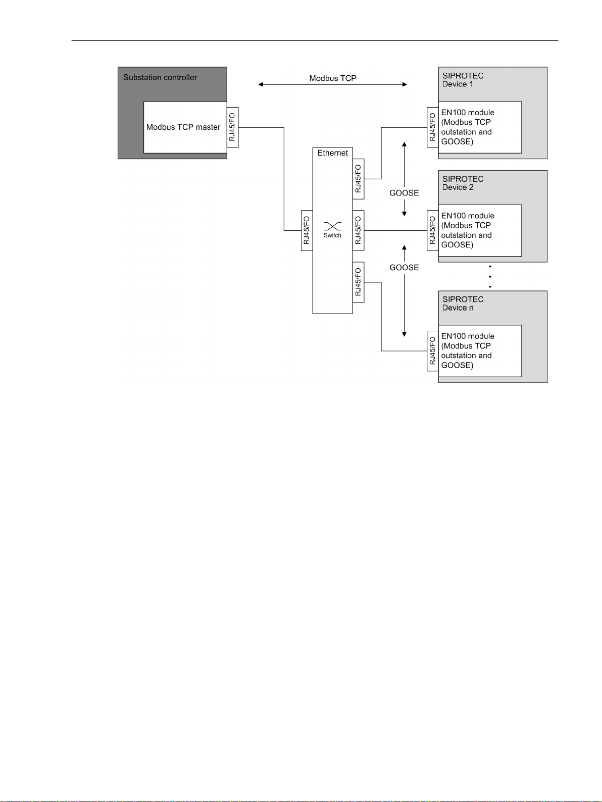
Application
The application Communication shows an example of the SIPROTEC 4 devices with Modbus TCP and
GOOSE. Modbus TCP is used for communication to a substation controller and GOOSE is used for interdevice data exchange.
10 SIPROTEC 4, Modbus TCP Profile, Manual
C53000-L1840-C582-1, Edition 07.2015
Characteristic of the ModbusTCP Module
1.1 General
[dw_appl_communication, 1, en_US]
Figure 1-1
Bus-Mapping Documents
You can download the bus mapping document for each device type at the following address:
http://siemens.siprotec.de/download_neu/index_e.html
The data objects, available via Modbus TCP, are described in the following manual:
7SJ80 / 7SK80 Modbus Bus Mapping, order number C53000-L1878-C581.
Accessories
The following Ethernet Patch Cables are available (double shielded (SFPT), LAN connector plugs on both
sides):
Cable Length
0.5 m 7KE6000-8G-D00-0AA5
1.0 m 7KE6000-8G-D00-1AA0
2.0 m 7KE6000-8G-D00-2AA0
3.0 m 7KE6000-8G-D00-3AA0
5.0 m 7KE6000-8G-D00-5AA0
10.0 m 7KE6000-8G-D01-0AA0
15.0 m 7KE6000-8G-D01-5AA0
20.0 m 7KE6000-8G-D02-0AA0
Application Communication
Order Number
SIPROTEC 4, Modbus TCP Profile, Manual 11
C53000-L1840-C582-1, Edition 07.2015
Characteristic of the ModbusTCP Module
1.2 Identification of Module and Firmware
1.2
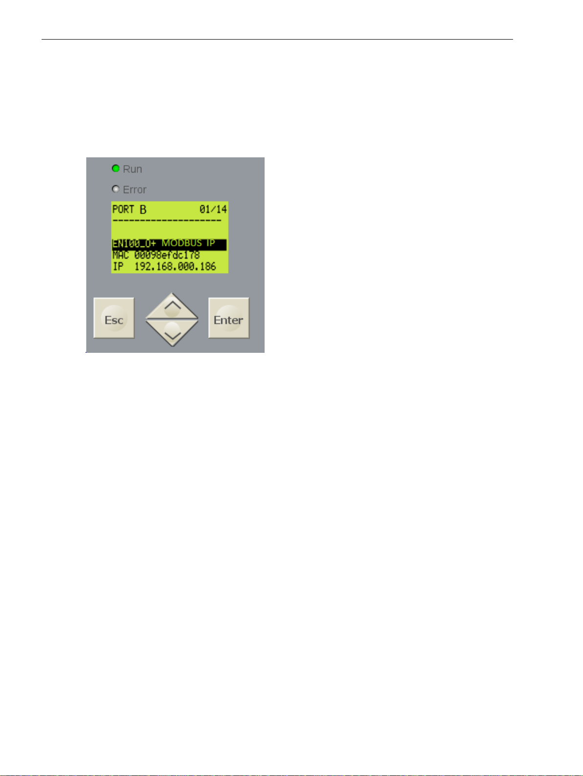
Modulinfo Menu
Identification of Module and Firmware
The Menu is available on the HMI display or via WebMonitor:
²
The menue shows for example module type, communication protocol, and network settings.
Select Enter → Test/Diagnosis → Modulinfo → Port B.
[sc_Modulinfo, 1, en_US]
Figure 1-2 Modulinfo
Module type:
EN100+ EN100+ module with electrical Ethernet interface
EN100_O+ EN100+ module with fiber-optic Ethernet interface
Communication protocol:
IEC61850 IEC 61850/GOOSE
EN100_O+Modbus TCP Modbus TCP with IEC61850/GOOSE option (see chapter Further Ethernet Serv-
MLFB/Version Menu
The Menue is available on the HMI display or via WebMonitor:
Select Enter → Settings → Setup/Extras → MLFB/Version.
²
Scroll down until the version number of the firmware on EN100+ module is shown.
²
ices and Protocols)
12 SIPROTEC 4, Modbus TCP Profile, Manual
C53000-L1840-C582-1, Edition 07.2015
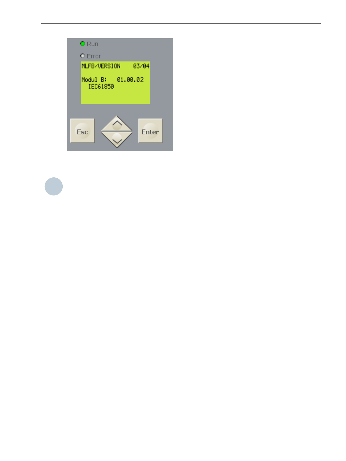
[sc_MLFBVersion, 1, en_US]
i
i
Figure 1-3 MLFB/Version
NOTE
Characteristic of the ModbusTCP Module
1.2 Identification of Module and Firmware
The firmware identification of IEC 61850 is shown here, even if the Modbus TCP firmware is loaded.
HTML page of the EN100+ module:
If Modbus TCP firmware is loaded, the menu Modbus TCP is available in the navigation pane.
The firmware version is shown on the homepage.
Refer to chapter
5.1 HTML Page
SIPROTEC 4, Modbus TCP Profile, Manual 13
C53000-L1840-C582-1, Edition 07.2015

i
i
Characteristic of the ModbusTCP Module
1.3 Supported Modbus Functions and Register Types
1.3
Supported Modbus Functions and Register Types
The Modbus TCP interface of the SIPROTEC 4 device supports the following function and register types:
Function
Code
Function Name Description Broadcast
1 Read Coil Status
(0X references)
2 Read Input Status
(1X references)
3 Read Holding Registers
(4X references)
4 Read Input Registers
(3X references)
5 Force Single Coil
(0X references)
7 Read Exception Status This function responds the value of the 8 Coil Status regis-
15 Force Multiple Coils
(0X references)
16 Preset Multiple Regs
(4X references)
Reading 1 or several Coil Status registers of the Modbus
slave.
The Coil Status registers reflect the ON/OFF status of
discrete outputs of the SIPROTEC 4 device.
Reading 1 or several Input Status registers of the Modbus
slave.
The Input Status registers reflect the ON/OFF status of
discrete inputs and the status of the protection function of
the SIPROTEC 4 device.
Reading 1 or several Holding Registers of the Modbus
slave.
The Holding Registers contain device-status information,
mean values of measured values, metered measurands
and others.
Reading 1 or several Input registers of the Modbus slave.
The Input registers contain recorded measured values.
Writing (force to ON or OFF) 1 Coil Status registers (and
the assigned binary input of the SIPROTEC 4 device).
Use function code 15 to force multiple Coil Status registers.
ters 257..264 as Exception Status to the Modbus master.
Writing (force to ON or OFF) 1 or several Coil Status registers (and the assigned binary input of the SIPROTEC 4
device).
Function presets 1 or several Holding Registers. yes
is
supported
no
no
no
no
yes
no
yes
NOTE
Broadcast messages from the Modbus master to the Modbus slaves using slave address 0 in the Modbus
message.
Type Number Register Name Object Type
0 Coil Status
(0x references)
1 Input Status
(1X references)
3 Input Registers
(3X references)
14 SIPROTEC 4, Modbus TCP Profile, Manual
Double-point command,
Single-point command,
Double-point indication,
Single-point indication
Protection indication,
Device-status indication
Measurement values
C53000-L1840-C582-1, Edition 07.2015

Characteristic of the ModbusTCP Module
1.3 Supported Modbus Functions and Register Types
Type Number Register Name Object Type
4 Holding Registers
(4X references)
System information,
Time synchronization,
Diagnostic information,
Metered measurands,
Statistic values,
Min/Max values of measured values
SIPROTEC 4, Modbus TCP Profile, Manual 15
C53000-L1840-C582-1, Edition 07.2015

i
i
Characteristic of the ModbusTCP Module
1.4 Table of Parameters
1.4
Table of Parameters
The following Modbus TCP-specific configuration settings are available in the SIPROTEC 4 device. For
further Information to the Modbus TCP mapping file see chapter 2).
Table 1-1 Modbus TCP-Specific Settings
Parameter Default
Setting
Slave Address 1 1 to 247 Modbus TCP station address of
TCPPortNumber 502,
504
EnableTimeSynchronization 0 0,1
CoilBroadcastMsg 1 0,1
HoldingBroadcastMsg 1 0,1
UseSetTimeAndDateReg 0 0,1
SingleBitDoubleCmdCtrl 0 0,1
ExceptionMsgAtInvalidData 0 0,1
Setting Range Description
the device
100 to 65535
TcpPortNumber1 = 502
TcpPortNumber2 = 504
1 = Enable Modbus-IP time sync.
0 = Disable Modbus-IP time sync.
0 = no
1 = yes
0 = no
1 = yes
1 = Use Set Date and Time
register for acceptance of
previous written time synchronization data.
0 = time synchronization data are
valid at the time of writing.
1 = using functions Force Single
Coil or Force Multiple Coils.
0 = using function Force Multiple
Coils only
1 = yes; only Read Input Register
and write commands are
executed.
0 = no; a bit in the Diagnostics
Register indicates Data Invalid.
The TCP ports to listen on
Enable Modbus-IP time synchronization
Accept broadcast messages for
Coil Status Register using functions Force Single Coil and Force
Multiple Coils
Accept broadcast messages for
Holding Register using functions
Preset Single Register and Preset
Multiple Regs
Two methods of data acceptance
for time synchronization of the
SIPROTEC 4 device via Modbus
are possible.
Control mode of double
commands.
Respond with Modbus exception
SLAVE_DEVICE_BUSY to
Modbus TCP master during the
period of Data Invalid error.
NOTE
The settings above are valid for all Modbus TCP connections in the same way; they cannot be configured
individually for each Modbus TCP connection or for each connected Modbus TCP master..
During startup of the Ethernet module, the configuration of all Modbus TCP parameters is checked. If a
parameter value is detected outside the valid range, an error-log entry is issued on the EN100+ module
and the parameter is set to its default value (see
16 SIPROTEC 4, Modbus TCP Profile, Manual
Figure 5-2
).
C53000-L1840-C582-1, Edition 07.2015
Characteristic of the ModbusTCP Module
1.5 Further Ethernet Services and Protocols
1.5
1.5.1
1.5.2
Further Ethernet Services and Protocols
The following additional services and protocols are supported on the EN100+ module.
With DIGSI 4 these services can be switched ON or OFF.
For security reasons, Siemens recommends switching OFF unused services.
Services
Module homepage (HTTP)
•
Firmware upgrade (HTTP)
•
DIGSI 4 over EN100+
•
IEC 61850 and GOOSE
•
SNTP (see Chapter
•
For further information, refer to the manual
Ethernet Module EN100+ for IEC 61850 with electrical/optical 100 Mbit Interface, Order number C53000-
G1140-C167.
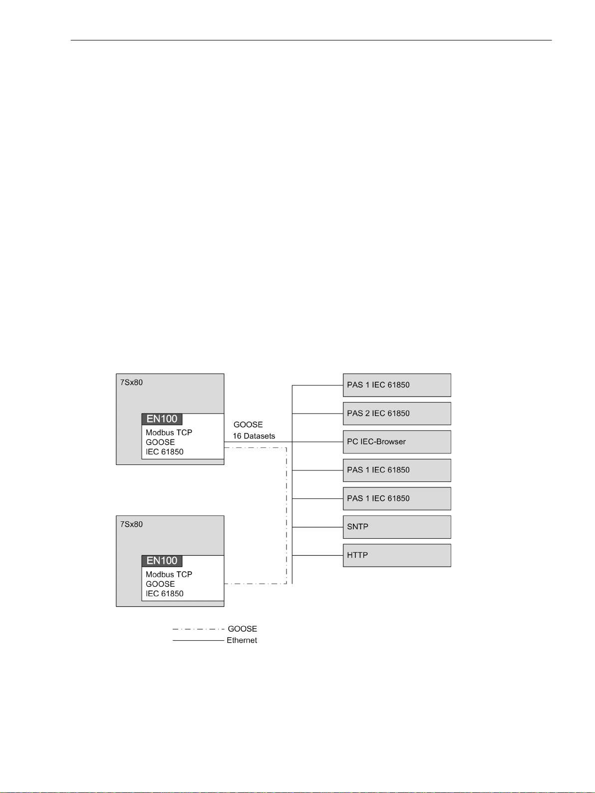
Modbus TCP with IEC 61850 and GOOSE
The following figure shows the communication the communication via Modbus TCP with IEC 61850 and
GOOSE.
4.2 Time Synchronization with Modbus TCP
)
[dw_modbus-tcp-with-iec61850, 1, en_US]
Figure 1-4
SIPROTEC 4, Modbus TCP Profile, Manual 17
C53000-L1840-C582-1, Edition 07.2015
Modbus TCP with IEC 61850 and GOOSE

18 SIPROTEC 4, Modbus TCP Profile, Manual
C53000-L1840-C582-1, Edition 07.2015

2
Configuration in DIGSI 4
2.1 Inserting and Adjusting a New Project 20
2.2 Setting the Interfaces 27
2.3 Customization of the Allocations 30
SIPROTEC 4, Modbus TCP Profile, Manual 19
C53000-L1840-C582-1, Edition 07.2015
 Loading...