

Page 1

Preface
Table of Contents
SIPROTEC 4
Multi-funktional Protective
Relay with Bay Controller
7SJ61
V4.9
Manual
Introduction
Functions
Mounting and Commissioning
Technical Data
Ordering Information and Accessories
Terminal Assignments
Connection Examples
Current Transformer Requirements
Default Settings and Protocol-dependent
Functions
1
2
3
4
A
B
C
D
E
C53000-G1140-C210-6
Functions, Settings, Information
Literature
Glossary
Index
F
Page 2

i
i
NOTE
For your own safety, observe the warnings and safety instructions contained in this document, if available.
Disclaimer of Liability
We have checked the contents of this manual against the
hardware and software described. However, deviations
from the description cannot be completely ruled out, so
that no liability can be accepted for any errors or omissions
contained in the information given.
The information given in this document is reviewed regularly and any necessary corrections will be included in
subsequent editions. We appreciate any suggested
improvements.
We reserve the right to make technical improvements
without notice.
Document version V04.41.00
Release date 05.2016
Copyright
Copyright © Siemens AG 2016. All rights reserved.
Dissemination or reproduction of this document, or evalua-
tion and communication of its contents, is not authorized
except where expressly permitted. Violations are liable for
damages. All rights reserved, particularly for the purposes
of patent application or trademark registration.
Registered Trademarks
SIPROTEC, SINAUT, SICAM and DIGSI are registered trademarks of Siemens AG. Other designations in this manual
might be trademarks whose use by third parties for their
own purposes would infringe the rights of the owner
Page 3

Preface
Purpose of this Manual
This manual describes the functions, operation, installation, and commissioning of devices 7SJ61. In particular, one will find:
Information regarding the configuration of the scope of the device and a description of the device func-
•
tions and settings → Chapter 2;
Instructions for Installation and Commissioning → Chapter 3;
•
Compilation of the Technical Data → Chapter 4;
•
As well as a compilation of the most significant data for advanced users → Appendix A.
•
General information with regard to design, configuration, and operation of SIPROTEC 4 devices are set out in
the SIPROTEC 4 System Description /1/ SIPROTEC 4 Systembeschreibung.
Target Audience
Protection-system engineers, commissioning engineers, persons entrusted with the setting, testing and maintenance of selective protection, automation and control equipment, and operating personnel in electrical
installations and power plants.
Applicability of this Manual
This manual applies to: SIPROTEC 4 Multi-funktional Protective Relay with Bay Controller 7SJ61; firmware
version V4.9.
Indication of Conformity
Additional Standards IEEE Std C37.90 (see Chapter 4 "Technical Data")
[ul-schutz-110602-kn, 1, --_--]
This product complies with the directive of the Council of the European Communities on the
approximation of the laws of the Member States relating to electromagnetic compatibility
(EMC Council Directive 2004/108/EC) and concerning electrical equipment for use within
specified voltage limits (Low-voltage Directive 2006/95 EC).
This conformity is proved by tests conducted by Siemens AG in accordance with the Council
Directive in agreement with the generic standards EN 61000-6-2 and EN 61000-6-4 for EMC
directive, and with the standard EN 60255-27 for the low-voltage directive.
The device has been designed and produced for industrial use.
The product conforms with the international standards of the series IEC 60255 and the
German standard VDE 0435.
SIPROTEC 4, 7SJ61, Manual
C53000-G1140-C210-6, Edition 05.2016
3
Page 4

!
!
!
Preface
Additional Support
For questions about the SIPROTEC 4 system, please contact your Siemens sales partner.
Our Customer Support Center provides a 24-hour service.
Phone: +49 (180) 524-8437
Fax: +49 (180) 524-2471
e-mail: support.ic@siemens.com
Training Courses
Enquiries regarding individual training courses should be addressed to our Training Center:
Siemens AG
Siemens Power Academy TD
Humboldt Street 59 59
90459 Nuremberg
Phone: +49 (911) 433-7415
Fax: +49 (911) 433-5482
Internet: www.siemens.com/energy/power-academy
e-mail: poweracademy.ic-sg@siemens.com
Safety Information
This manual does not constitute a complete index of all required safety measures for operation of the equipment (module, device), as special operational conditions may require additional measures. However, it
comprises important information that should be noted for purposes of personal safety as well as avoiding
material damage. Information that is highlighted by means of a warning triangle and according to the degree
of danger, is illustrated as follows.
DANGER
Danger indicates that death, severe personal injury or substantial material damage will result if proper
precautions are not taken.
²
WARNING
indicates that death, severe personal injury or substantial property damage may result if proper precautions
are not taken.
²
CAUTION
indicates that minor personal injury or property damage may result if proper precautions are not taken. This
particularly applies to damage to or within the device itself and consequential damage thereof.
²
4 SIPROTEC 4, 7SJ61, Manual
C53000-G1140-C210-6, Edition 05.2016
Page 5

i
i
!
Preface
NOTE
indicates information on the device, handling of the device, or the respective part of the instruction manual
which is important to be noted.
WARNING
Qualified Personnel
Commissioning and operation of the equipment (module, device) as set out in this manual may only be
carried out by qualified personnel. Qualified personnel in terms of the technical safety information as set
out in this manual are persons who are authorized to commission, activate, to ground and to designate
devices, systems and electrical circuits in accordance with the safety standards.
Use as prescribed
The operational equipment (device, module) may only be used for such applications as set out in the catalogue and the technical description, and only in combination with third-party equipment recommended or
approved by Siemens.
The successful and safe operation of the device is dependent on proper handling, storage, installation,
operation, and maintenance.
When operating an electrical equipment, certain parts of the device are inevitably subject to dangerous
voltage. Severe personal injury or property damage may result if the device is not handled properly.
Before any connections are made, the device must be grounded to the ground terminal.
All circuit components connected to the voltage supply may be subject to dangerous voltage.
Dangerous voltage may be present in the device even after the power supply voltage has been removed
(capacitors can still be charged).
Operational equipment with open circuited current transformer circuits may not be operated.
The limit values as specified in this manual or in the operating instructions may not be exceeded. This
aspect must also be observed during testing and commissioning.
²
Typographic and Symbol Conventions
The following text formats are used when literal information from the device or to the device appear in the
text flow:
Parameter Names
Designators of configuration or function parameters which may appear word-for-word in the display of the
device or on the screen of a personal computer (with operation software DIGSI), are marked in bold letters in
monospace type style. The same applies to titles of menus.
1234A
Parameter addresses have the same character style as parameter names. Parameter addresses contain the
suffix A in the overview tables if the parameter can only be set in DIGSI via the option Display additional
settings.
Parameter Options
Possible settings of text parameters, which may appear word-for-word in the display of the device or on the
screen of a personal computer (with operation software DIGSI), are additionally written in italics. The same
applies to the options of the menus.
Indications
Designators for information, which may be output by the relay or required from other devices or from the
switch gear, are marked in a monospace type style in quotation marks.
Deviations may be permitted in drawings and tables when the type of designator can be obviously derived
from the illustration.
The following symbols are used in drawings:
SIPROTEC 4, 7SJ61, Manual 5
C53000-G1140-C210-6, Edition 05.2016
Page 6
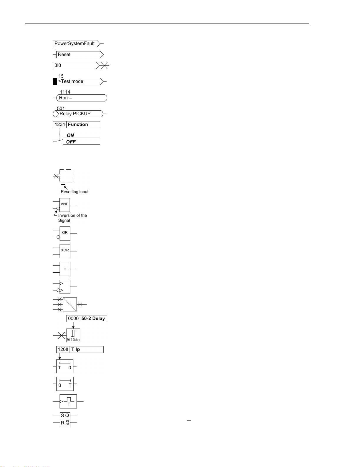
Preface
Device-internal logical input signal
Device-internal logical output signal
Internal input signal of an analog quantity
External binary input signal with number (binary input,
input indication)
External binary output signal with number
(example of a value indication)
External binary output signal with number (device indication) used as
input signal
Example of a parameter switch designated FUNCTION with address
1234 and the possible settings ON and OFF
Besides these, graphical symbols are used in accordance with IEC 60617-12 and IEC 60617-13 or similar.
Some of the most frequently used are listed below:
Analog input variable
AND-gate operation of input values
OR-gate operation of input values
Exclusive OR gate (antivalence): output is active, if only one of the
inputs is active
Coincidence gate: output is active, if both inputs are active or inactive
at the same time
Dynamic inputs (edge-triggered) above with positive, below with
negative edge
Formation of one analog output signal from a number of analog input
signals
Limit stage with setting address and parameter designator (name)
Timer (pickup delay T, example adjustable) with setting address and
parameter designator (name)
Timer (dropout delay T, example non-adjustable)
Dynamic triggered pulse timer T (monoflop)
Static memory (SR flipflop) with setting input (S), resetting input (R),
output (Q) and inverted output (Q), setting input dominant
6 SIPROTEC 4, 7SJ61, Manual
C53000-G1140-C210-6, Edition 05.2016
Page 7

Static memory (RS-flipflop) with setting input (S), resetting input (R),
output (Q) and inverted output (Q), resetting input dominant
Preface
SIPROTEC 4, 7SJ61, Manual 7
C53000-G1140-C210-6, Edition 05.2016
Page 8

8 SIPROTEC 4, 7SJ61, Manual
C53000-G1140-C210-6, Edition 05.2016
Page 9

Table of Contents
Preface..........................................................................................................................................................3
1 Introduction................................................................................................................................................17
1.1 Overall Operation..............................................................................................................18
1.2 Application Scope............................................................................................................. 20
1.3 Characteristics.................................................................................................................. 22
2 Functions.................................................................................................................................................... 27
2.1 General.............................................................................................................................28
2.1.1 Functional Scope......................................................................................................... 28
2.1.1.1 Description............................................................................................................ 28
2.1.1.2 Setting Notes......................................................................................................... 28
2.1.1.3 Settings................................................................................................................. 29
2.1.2 Device, General Settings.............................................................................................. 31
2.1.2.1 Command-dependent Messages.............................................................................31
2.1.2.2 Setting Notes......................................................................................................... 32
2.1.2.3 Settings................................................................................................................. 33
2.1.2.4 Information List..................................................................................................... 33
2.1.3 Power System Data 1...................................................................................................35
2.1.3.1 Description............................................................................................................ 35
2.1.3.2 Setting Notes......................................................................................................... 35
2.1.3.3 Settings................................................................................................................. 39
2.1.3.4 Information List..................................................................................................... 40
2.1.4 Oscillographic Fault Records........................................................................................ 41
2.1.4.1 Description............................................................................................................ 41
2.1.4.2 Setting Notes......................................................................................................... 41
2.1.4.3 Settings................................................................................................................. 42
2.1.4.4 Information List..................................................................................................... 42
2.1.5 Settings Groups........................................................................................................... 42
2.1.5.1 Description............................................................................................................ 42
2.1.5.2 Setting Notes......................................................................................................... 43
2.1.5.3 Settings................................................................................................................. 43
2.1.5.4 Information List..................................................................................................... 43
2.1.6 Power System Data 2...................................................................................................43
2.1.6.1 Description............................................................................................................ 43
2.1.6.2 Setting Notes......................................................................................................... 44
2.1.6.3 Settings................................................................................................................. 44
2.1.6.4 Information List..................................................................................................... 44
2.1.7 EN100-Module............................................................................................................ 45
2.1.7.1 Description............................................................................................................ 45
2.1.7.2 Setting Notes......................................................................................................... 45
2.1.7.3 Information List..................................................................................................... 45
2.2 Overcurrent Protection 50, 51, 50N, 51N.......................................................................... 46
2.2.1 General ...................................................................................................................... 46
SIPROTEC 4, 7SJ61, Manual 9
C53000-G1140-C210-6, Edition 05.2016
Page 10

Table of Contents
2.2.2 Definite Time, High-set Elements 50-3, 50-2, 50N-3, 50N-2..........................................47
2.2.3 Definite Time Overcurrent Elements 50-1, 50N-1......................................................... 49
2.2.4 Inverse Time Overcurrent Elements 51, 51N ................................................................52
2.2.5 Dynamic Cold Load Pickup Function.............................................................................55
2.2.6 Inrush Restraint .......................................................................................................... 55
2.2.7 Pickup Logic and Tripping Logic................................................................................... 57
2.2.8 Two-phase Overcurrent Protection (Only Non-Directional) ...........................................58
2.2.9 Fast Busbar Protection Using Reverse Interlocking ....................................................... 59
2.2.10 Setting Notes...............................................................................................................59
2.2.11 Settings.......................................................................................................................67
2.2.12 Information List...........................................................................................................69
2.3 Dynamic Cold Load Pickup.................................................................................................72
2.3.1 Description..................................................................................................................72
2.3.2 Setting Notes...............................................................................................................74
2.3.3 Settings.......................................................................................................................75
2.3.4 Information List...........................................................................................................76
2.4 Single-Phase Overcurrent Protection..................................................................................77
2.4.1 Description..................................................................................................................77
2.4.2 High-impedance Ground Fault Unit Protection............................................................. 78
2.4.3 Tank Leakage Protection..............................................................................................80
2.4.4 Setting Notes...............................................................................................................81
2.4.5 Settings.......................................................................................................................86
2.4.6 Information List...........................................................................................................86
2.5 Negative Sequence Protection 46......................................................................................87
2.5.1 Definite Time characteristic .........................................................................................87
2.5.2 Inverse Time characteristic 46-TOC.............................................................................. 88
2.5.3 Setting Notes...............................................................................................................90
2.5.4 Settings.......................................................................................................................92
2.5.5 Information List...........................................................................................................93
2.6 Motor Protection...............................................................................................................94
2.6.1 Motor Starting Protection 48........................................................................................94
2.6.1.1 Description............................................................................................................ 94
2.6.1.2 Setting Notes......................................................................................................... 97
2.6.2 Motor Restart Inhibit 66...............................................................................................98
2.6.2.1 Description............................................................................................................ 99
2.6.2.2 Setting Notes....................................................................................................... 103
2.6.3 Load Jam Protection (51M)........................................................................................ 107
2.6.3.1 Description.......................................................................................................... 107
2.6.3.2 Setting Notes....................................................................................................... 109
2.6.4 Motorprotection (Motor Starting Protection 48, Motor Restart Inhibit 66, LoadJam)....111
2.6.4.1 Settings............................................................................................................... 111
2.6.4.2 Information List................................................................................................... 112
2.7 Thermal Overload Protection 49...................................................................................... 113
2.7.1 Description................................................................................................................113
2.7.2 Setting Notes.............................................................................................................115
2.7.3 Settings.....................................................................................................................119
2.7.4 Information List.........................................................................................................120
10 SIPROTEC 4, 7SJ61, Manual
C53000-G1140-C210-6, Edition 05.2016
Page 11

Table of Contents
2.8 Monitoring Functions......................................................................................................121
2.8.1 Measurement Supervision......................................................................................... 121
2.8.1.1 General................................................................................................................121
2.8.1.2 Hardware Monitoring .......................................................................................... 121
2.8.1.3 Software Monitoring ........................................................................................... 123
2.8.1.4 Monitoring of the External Transformer Circuits....................................................123
2.8.1.5 Setting Notes....................................................................................................... 124
2.8.1.6 Settings............................................................................................................... 125
2.8.1.7 Information List................................................................................................... 125
2.8.2 Trip Circuit Supervision 74TC..................................................................................... 126
2.8.2.1 Description.......................................................................................................... 126
2.8.2.2 Setting Notes....................................................................................................... 128
2.8.2.3 Settings............................................................................................................... 129
2.8.2.4 Information List................................................................................................... 129
2.8.3 Malfunction Responses of the Monitoring Functions.................................................. 129
2.8.3.1 Description.......................................................................................................... 129
2.9 Ground Fault Protection 64, 67N(s), 50N(s), 51N(s).........................................................132
2.9.1 Current Elements 50Ns, 51Ns.................................................................................... 132
2.9.2 Logic......................................................................................................................... 132
2.9.3 Setting Notes.............................................................................................................135
2.9.4 Settings.....................................................................................................................138
2.9.5 Information List.........................................................................................................140
2.10 Intermittent Ground Fault Protection...............................................................................141
2.10.1 Description................................................................................................................141
2.10.2 Setting Notes.............................................................................................................144
2.10.3 Settings.....................................................................................................................145
2.10.4 Information List.........................................................................................................145
2.11 Automatic Reclosing System 79.......................................................................................147
2.11.1 Program Execution.................................................................................................... 147
2.11.2 Blocking.................................................................................................................... 150
2.11.3 Status Recognition and Monitoring of the Circuit Breaker........................................... 152
2.11.4 Controlling Protection Elements.................................................................................153
2.11.5 Zone Sequencing / Fuse Saving Scheme..................................................................... 155
2.11.6 Setting Notes.............................................................................................................156
2.11.7 Settings.....................................................................................................................161
2.11.8 Information List.........................................................................................................165
2.12 Breaker Failure Protection 50BF.......................................................................................167
2.12.1 Description................................................................................................................167
2.12.2 Setting Notes.............................................................................................................170
2.12.3 Settings.....................................................................................................................172
2.12.4 Information List.........................................................................................................173
2.13 Flexible Protection Functions...........................................................................................174
2.13.1 Functional Description...............................................................................................174
2.13.2 Setting Notes.............................................................................................................177
2.13.3 Settings.....................................................................................................................180
2.13.4 Information List.........................................................................................................181
2.14 Temperature Detection via RTD Boxes..............................................................................182
2.14.1 Description................................................................................................................182
SIPROTEC 4, 7SJ61, Manual 11
C53000-G1140-C210-6, Edition 05.2016
Page 12

Table of Contents
2.14.2 Setting Notes.............................................................................................................183
2.14.3 Settings.....................................................................................................................184
2.14.4 Information List.........................................................................................................188
2.15 Phase Rotation................................................................................................................ 190
2.15.1 Description................................................................................................................190
2.15.2 Setting Notes.............................................................................................................190
2.16 Function Logic................................................................................................................ 191
2.16.1 Pickup Logic of the Entire Device................................................................................191
2.16.2 Tripping Logic of the Entire Device.............................................................................191
2.16.3 Setting Notes.............................................................................................................192
2.17 Auxiliary Functions..........................................................................................................193
2.17.1 Message Processing...................................................................................................193
2.17.1.1 LED Displays and Binary Outputs (Output Relays)..................................................193
2.17.1.2 Information on the Integrated Display (LCD) or Personal Computer....................... 193
2.17.1.3 Information to a Substation Control Center...........................................................195
2.17.2 Statistics....................................................................................................................195
2.17.2.1 Description.......................................................................................................... 195
2.17.2.2 Circuit Breaker Maintenance.................................................................................196
2.17.2.3 Motor Statistics.................................................................................................... 202
2.17.2.4 Setting Notes....................................................................................................... 203
2.17.2.5 Information List................................................................................................... 204
2.17.2.6 Information List................................................................................................... 205
2.17.3 Measurement............................................................................................................205
2.17.3.1 Display of Measured Values.................................................................................. 206
2.17.3.2 Transfer of Measured Values................................................................................ 206
2.17.3.3 Information List................................................................................................... 207
2.17.4 Average Measurements............................................................................................. 208
2.17.4.1 Description.......................................................................................................... 208
2.17.4.2 Setting Notes....................................................................................................... 208
2.17.4.3 Settings............................................................................................................... 208
2.17.4.4 Information List................................................................................................... 208
2.17.5 Min/Max Measurement Setup.................................................................................... 209
2.17.5.1 Description.......................................................................................................... 209
2.17.5.2 Setting Notes....................................................................................................... 209
2.17.5.3 Settings............................................................................................................... 209
2.17.5.4 Information List................................................................................................... 209
2.17.6 Set Points for Measured Values.................................................................................. 210
2.17.6.1 Description.......................................................................................................... 210
2.17.6.2 Setting Notes....................................................................................................... 210
2.17.6.3 Information List................................................................................................... 211
2.17.7 Set Points for Statistic................................................................................................ 211
2.17.7.1 Description.......................................................................................................... 211
2.17.7.2 Setting Notes....................................................................................................... 211
2.17.7.3 Information List................................................................................................... 211
2.17.8 Commissioning Aids.................................................................................................. 211
2.17.8.1 Description.......................................................................................................... 212
2.17.9 Web Monitor............................................................................................................. 213
2.17.9.1 General................................................................................................................213
2.17.9.2 Functions.............................................................................................................214
2.17.9.3 Operating Modes ................................................................................................ 215
2.17.9.4 Display Example...................................................................................................216
2.17.9.5 Setting Notes....................................................................................................... 217
12 SIPROTEC 4, 7SJ61, Manual
C53000-G1140-C210-6, Edition 05.2016
Page 13

Table of Contents
2.18 Breaker Control...............................................................................................................219
2.18.1 Control Device...........................................................................................................219
2.18.1.1 Description.......................................................................................................... 219
2.18.1.2 Information List................................................................................................... 219
2.18.2 Types of Commands.................................................................................................. 220
2.18.2.1 Description.......................................................................................................... 220
2.18.3 Command Sequence..................................................................................................220
2.18.3.1 Description.......................................................................................................... 221
2.18.4 Interlocking............................................................................................................... 221
2.18.4.1 Description.......................................................................................................... 221
2.18.5 Command Logging.................................................................................................... 228
2.18.5.1 Description.......................................................................................................... 228
3 Mounting and Commissioning................................................................................................................. 231
3.1 Mounting and Connections............................................................................................. 232
3.1.1 Configuration Information......................................................................................... 232
3.1.2 Hardware Modifications.............................................................................................235
3.1.2.1 General................................................................................................................235
3.1.2.2 Disassembly.........................................................................................................237
3.1.2.3 Switch elements on the PCBs................................................................................239
3.1.2.4 Interface Modules................................................................................................ 251
3.1.2.5 Reassembly..........................................................................................................255
3.1.3 Installation................................................................................................................ 255
3.1.3.1 Panel Flush Mounting...........................................................................................255
3.1.3.2 Rack Mounting and Cubicle Mounting.................................................................. 257
3.1.3.3 Panel Flush Mounting...........................................................................................259
3.2 Checking Connections.....................................................................................................260
3.2.1 Checking Data Connections of Interfaces................................................................... 260
3.2.2 Checking the System Connections............................................................................. 262
3.3 Commissioning............................................................................................................... 265
3.3.1 Test Mode and Transmission Block.............................................................................266
3.3.2 Testing the System Interface .....................................................................................266
3.3.3 Checking the Status of Binary Inputs and Outputs...................................................... 267
3.3.4 Tests for Breaker Failure Protection............................................................................ 270
3.3.5 Testing User-Defined Functions..................................................................................272
3.3.6 Current, and Phase Rotation Testing...........................................................................272
3.3.7 Test for High Impedance Protection........................................................................... 272
3.3.8 Testing the Reverse Interlocking Scheme....................................................................273
3.3.9 Checking the Temperature Detection......................................................................... 273
3.3.10 Trip/Close Tests for the Configured Operating Devices................................................ 274
3.3.11 Creating Oscillographic Recordings for Tests.............................................................. 275
3.3.12 Final Preparation of the Device.................................................................................. 276
4 Technical Data.......................................................................................................................................... 279
4.1 General Device Data........................................................................................................280
4.1.1 Analog Inputs............................................................................................................280
4.1.2 Auxiliary Voltage....................................................................................................... 280
4.1.3 Binary Inputs and Outputs .........................................................................................281
4.1.4 Communication Interfaces.........................................................................................282
4.1.5 Electrical Tests...........................................................................................................286
SIPROTEC 4, 7SJ61, Manual 13
C53000-G1140-C210-6, Edition 05.2016
Page 14

Table of Contents
4.1.6 Mechanical Tests....................................................................................................... 287
4.1.7 Climatic Stress Tests.................................................................................................. 288
4.1.8 Service Conditions..................................................................................................... 289
4.1.9 Certifications............................................................................................................. 289
4.1.10 Design ......................................................................................................................289
4.2 Definite-time Overcurrent Protection...............................................................................290
4.3 Inverse-time Overcurrent Protection................................................................................292
4.4 Inrush Restraint...............................................................................................................302
4.5 Dynamic Cold Load Pickup...............................................................................................303
4.6 Single-phase Overcurrent Protection............................................................................... 304
4.7 Negative Sequence Protection (definite-time characteristic).............................................305
4.8 Negative Sequence Protection (inverse-time characteristics)............................................306
4.9 Motor Starting Time Supervision..................................................................................... 312
4.10 Motor Restart Inhibit....................................................................................................... 313
4.11 Load Jam Protection........................................................................................................314
4.12 Thermal Overload Protection...........................................................................................315
4.13 Ground Fault Detection (Sensitive/Insensitive).................................................................317
4.14 Intermittent Ground Fault Protection...............................................................................324
4.15 Automatic Reclosing....................................................................................................... 325
4.16 Breaker Failure Protection............................................................................................... 326
4.17 Flexible Protection Functions ..........................................................................................327
4.18 Temperature Detection................................................................................................... 329
4.19 User-defined Functions (CFC).......................................................................................... 330
4.20 Auxiliary Functions..........................................................................................................336
4.21 Switching Device Control................................................................................................ 340
4.22 Dimensions.....................................................................................................................341
4.22.1
4.22.2
4.22.3
4.22.4
4.22.5 Varistor..................................................................................................................... 344
Panel Flush and Cubicle Mounting (Housing Size 1/3) ................................................. 341
Panel Flush Mounting and Cabinet Flush Mounting (Housing Size 1/2) ........................342
Panel Surface Mounting (Housing Size 1/3) .................................................................343
Panel Surface Mounting (Housing Size1/2) ................................................................. 343
A Ordering Information and Accessories.....................................................................................................345
A.1 Ordering Information 7SJ61 V4.9 ................................................................................... 346
A.2 Accessories.....................................................................................................................349
B Terminal Assignments..............................................................................................................................351
B.1 Housing for Panel Flush and Cubicle Mounting................................................................ 352
B.2 Housing for Panel Surface Mounting................................................................................355
B.3 Terminal Assignment on Housing for Panel Surface Mounting..........................................358
B.4 Connector Assignment....................................................................................................360
C Connection Examples............................................................................................................................... 361
C.1 Connection Examples for Current Transformers, all Devices............................................. 362
C.2 Connection Examples for RTD-Box, all Devices................................................................. 367
14 SIPROTEC 4, 7SJ61, Manual
C53000-G1140-C210-6, Edition 05.2016
Page 15

Table of Contents
D Current Transformer Requirements......................................................................................................... 369
D.1 Accuracy limiting factors................................................................................................. 370
D.2 Class conversion............................................................................................................. 371
D.3 Cable core balance current transformer........................................................................... 372
E Default Settings and Protocol-dependent Functions............................................................................... 373
E.1 LEDs............................................................................................................................... 374
E.2 Binary Input.................................................................................................................... 375
E.3 Binary Output................................................................................................................. 376
E.4 Function Keys................................................................................................................. 377
E.5 Default Display................................................................................................................378
E.6 Pre-defined CFC Charts....................................................................................................380
E.7 Protocol-dependent Functions.........................................................................................381
F Functions, Settings, Information..............................................................................................................383
F.1 Functional Scope............................................................................................................ 384
F.2 Settings.......................................................................................................................... 386
F.3 Information List.............................................................................................................. 406
F.4 Group Alarms..................................................................................................................437
F.5 Measured Values.............................................................................................................438
Literature.................................................................................................................................................. 441
Glossary.................................................................................................................................................... 443
Index.........................................................................................................................................................453
SIPROTEC 4, 7SJ61, Manual 15
C53000-G1140-C210-6, Edition 05.2016
Page 16

16 SIPROTEC 4, 7SJ61, Manual
C53000-G1140-C210-6, Edition 05.2016
Page 17

1
Introduction
The device family SIPROTEC 7SJ61 devices is introduced in this section. An overview of the devices is
presented in their application, characteristics, and scope of functions.
1.1 Overall Operation 18
1.2 Application Scope 20
1.3 Characteristics 22
SIPROTEC 4, 7SJ61, Manual 17
C53000-G1140-C210-6, Edition 05.2016
Page 18
Introduction
1.1 Overall Operation
1.1
Analog Inputs
Overall Operation
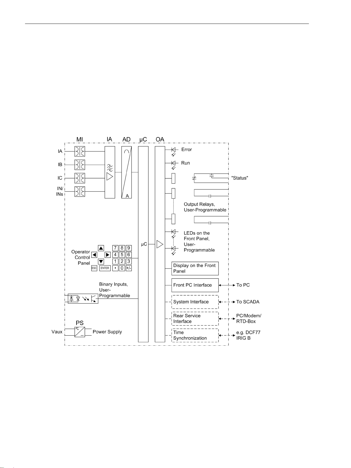
The numerical, multi-functional protection device SIPROTEC 7SJ61 is equipped with a powerful microprocessor. It allows all tasks to be processed digitally, from the acquisition of measured quantities to sending
commands to circuit breakers. Figure 1-1 shows the basic structure of the device.
The measuring inputs (MI) convert the currents coming from the instrument transformers and adapt them to
the level appropriate for the internal processing of the device. The device has 4 current inputs. three of these
are for the input of the phase currents. Depending on the model, the fourth current input (ΙN) may be used for
measuring the ground fault current ΙN (current transformer starpoint) or for a separate ground current transformer (for ground fault detection ΙNs). The analog input quantities are passed on to the input amplifiers (IA).
[hw-struktur-7sj61-020702-kn, 1, en_US]
Figure 1-1
The input amplifier IA stage provides a high-resistance termination for the input quantities. It consists of filters
that are optimized for measured-value processing with regard to bandwidth and processing speed.
The analog-to-digital (AD) element consists of a multiplexor, an analog-to-digital (A/D) converter and of
memory components for the transmission of digital signals to the microcomputer system.
Microcomputer System
Apart from processing the measured values, the microcomputer system (μC) also executes the actual protection and control functions. They especially include:
18 SIPROTEC 4, 7SJ61, Manual
Hardware structure of the numerical multi-functional device 7SJ61
C53000-G1140-C210-6, Edition 05.2016
Page 19

Filtering and preparation of the measured quantities
•
Continuous monitoring of the measured quantities
•
Monitoring of the pickup conditions for the individual protective functions
•
Interrogation of limit values and sequences in time
•
Control of signals for the logic functions
•
Output of control commands for switching devices
•
Recording of messages, fault data and fault values for analysis
•
Management of the operating system and the associated functions such as data recording, real-time
•
clock, communication, interfaces, etc.
The information is distributed via output amplifiers (OA).
•
Binary Inputs and Outputs
The computer system obtains external information through the binary input/output boards (inputs and
outputs). The computer system obtains information from the system (e.g remote resetting) or from external
equipment (e.g. blocking commands). These outputs include, in particular, trip commands to circuit breakers
and signals for the remote indication of important events and conditions.
Front Panel
Introduction
1.1 Overall Operation
Optical indicators (LEDs) and a front display panel (LC display) provide information on the function of the
device, and indicate events, states and measured values.
Integrated control and numeric keys in conjunction with the LCD enable interaction with the remote device.
These elements can be used to access the device for information such as configuration and setting parameters. Similarly, setting parameters can be accessed and changed if needed.
In addition, control of circuit breakers and other equipment is possible from the front panel of the device.
Serial Interfaces
The Front PC Interface is provided for local communications with a personal computer using the DIGSI software. This facilitates a comfortable handling of all device functions.
The Rear Service Interface can also be used to communicate with the relay from a PC running the DIGSI software. This interface is especially well suited for a permanent connection of the devices to the PC or for operation via a modem. The service interface can also be used to connect an RTD box (= resistance temperature
detector) for obtaining external temperatures (e.g. for overload protection).
All data can be transferred to a central control center or monitoring system via the serial System Interface.
This interface may be provided with various protocols and physical transmission schemes to suit the particular
application.
A further interface is provided for the time synchronization of the internal clock via external synchronization
sources.
A range of communication protocols are available from a variety of additional interface modules.
The operator or service interface allows you to operate the device from a remote location or on site using a
standard browser. This is possible during commissioning, checking and also during operation of the devices.
The SIPROTEC 4 Standard “WEBMonitor” is available for this task.
Power Supply
A power supply unit (Vaux or PS) delivers power to the functional units using the different voltage levels.
Voltage dips may occur if the voltage supply system (substation battery) becomes short-circuited. Usually,
they are bridged by a capacitor (see also Technical Data).
SIPROTEC 4, 7SJ61, Manual 19
C53000-G1140-C210-6, Edition 05.2016
Page 20

Introduction
1.2 Application Scope
1.2
Protective Functions
Application Scope
The numerical, multi-functional SIPROTEC 4 7SJ61 is a versatile device designed for protection, control and
monitoring of busbar feeders. For line protection, the device can be used in networks with earthed, low resistance earthed, isolated or compensated neutral point. It is suited for networks that are radial and supplied from
a single source or open looped networks. The device is equipped with motor protection applicable for asynchronous machines of all sizes.
The device includes the functions that are necessary for protection, for monitoring of circuit breaker positions,
and control of the circuit breakers in straight bus applications or breaker-and-a-half configurations; therefore,
the devices can be universally employed. The devices also provide excellent backup facilities of differential
protective schemes of lines, transformers, generators, motors, and busbars of all voltage levels.
Non-directional overcurrent protection (50, 50N, 51, 51N) is the basis of the device. There are three definite
time overcurrent protective elements and one inverse time element for the phase currents and the ground
current. For inverse time overcurrent protective elements, several curves of different standards are provided.
Alternatively, user-defined characteristic can be programmed.
Depending on the variant ordered, the overcurrent time protection can feature breaker failure protection and
ground fault protection for high-resistence ground short-circuits and faults.
In addition to the fault protection functions already mentioned, other protective functions are available. Some
of them depend on the version of the device that is ordered. These additional functions include negative
sequence protection (46), thermal overload protection (49) with start inhibit for motors (66/68), and motor
starting protection (48), as well as automatic reclosing (79) which allows different reclosing cycles on overhead lines. An automatic reclosing system may also be connected externally.
A protection feature can be ordered for the detection of intermittent ground faults which detects and accumulates transient ground faults.
External detectors account for ambient temperatures or coolant temperatures (by means of an external
RTDbox).
Control Functions
The device features a control function for activating and deactivating switchgears via the integrated operator
panel, the system interface, binary inputs, and the serial port using a personal computer with DIGSI.
The status of the primary equipment can be transmitted to the device via auxiliary contacts connected to
binary inputs. The present status (or position) of the primary equipment can be displayed on the device, and
used for interlocking or alarm condition monitoring. The number of operating equipments to be switched is
limited by the binary inputs and outputs available in the device or the binary inputs and outputs allocated for
the switch position indications. Depending on the primary equipment being controlled, one binary input
(single point indication) or two binary inputs (double point indication) may be used for this process.
The capability of switching primary equipment can be restricted by a setting associated with switching
authority (Remote or Local), and by the operating mode (interlocked/non-interlocked, with or without password request).
Processing of interlocking conditions for switching (e.g. switchgear interlocking) can be established with the
aid of integrated, user-configurable logic functions.
Messages and Measured Values; Recording of Event and Fault Data
The operational indications provide information about conditions in the power system and the device. Measurement quantities and values that are calculated can be displayed locally and communicated via the serial
interfaces.
Device messages can be assigned to a number of LEDs on the front cover (allocatable), can be externally
processed via output contacts (allocatable), linked with user-definable logic functions and/or issued via serial
interfaces.
During a fault (system fault) important events and changes in conditions are saved in fault protocols (Event
Log or Trip Log). Instantaneous fault values are also saved in the device and may be analyzed subsequently.
20 SIPROTEC 4, 7SJ61, Manual
C53000-G1140-C210-6, Edition 05.2016
Page 21

Communication
The following interfaces are available for the communication with external operating, control and memory
systems.
A 9-pole DSUB miniature female connector on the front panel serves the purpose of local communication with
a PC. By means of the SIPROTEC 4 operating software DIGSI, all operational and evaluation tasks can be
executed via this operator interface, such as specifying and modifying configuration parameters and settings,
configuring user-specific logic functions, retrieving operational messages and measured values, inquiring
device conditions and measured values, issuing control commands.
Depending on the individual ordering variant, additional interfaces are located at the rear side of the device.
They serve to establish extensive communication with other digital operating, control and memory components.
The service interface can be operated via electrical data lines or fiber optics and also allows communication
via modem. For this reason, remote operation is possible via personal computer and the DIGSI operating software, e.g. to operate several devices via a central PC.
The system interface ensures the central communication between the device and the substation controller. It
can also be operated via data lines or fibre optic cables. Standard protocols are available to transmit data
according to IEC 60870-5-103 via system port. The integration of the devices into the automation systems
SINAUT LSA and SICAM can also take place with this profile.
An EN 100 module allows integrating the devices into 100-Mbit Ethernet communication networks of the
process control and automation system using IEC 61850, PROFINET or DNP 3.0 TCP protocols. Besides the link
with the process control and automation system, this interface also processes DIGSI communication, interrelay
communication via GOOSE and connection of a SICAM I/O unit.
Alternatively, field bus coupling with PROFIBUS FMS is available for SIPROTEC 4. The PROFIBUS FMS according
to DIN 19245 is an open communication standard that particularly has wide acceptance in process control and
automation engineering, with exceptional high performance. A profile has been defined for the PROFIBUS
communication that covers all of the information types required for protection and process control engineering. The integration of the devices into the power automation system SICAM can also take place with this
profile.
Besides the field-bus connection with PROFIBUS FMS, further coupling options are possible with PROFIBUS DP
and the protocols DNP 3.0 and MODBUS. These protocols do not support all possibilities which are offered by
PROFIBUS FMS.
Furthermore, a redundant IEC 60870-5-103 interface is available.
Introduction
1.2 Application Scope
SIPROTEC 4, 7SJ61, Manual 21
C53000-G1140-C210-6, Edition 05.2016
Page 22

Introduction
1.3 Characteristics
1.3
General Characteristics
Characteristics
Powerful 32-bit microprocessor system
•
Complete digital processing and control of measured values, from the sampling of the analog input quan-
•
tities to the initiation of outputs, for example, tripping or closing circuit breakers or other switchgear
devices
Total electrical separation between the internal processing stages of the device and the external trans-
•
former, control, and DC supply circuits of the system because of the design of the binary inputs, outputs,
and the DC or AC converters
Complete set of functions necessary for the proper protection of lines, feeders, motors, and busbars
•
Easy device operation through an integrated operator panel or by means of a connected personal
•
computer running DIGSI
Continuous calculation and display of measured and metered values on the front of the device
•
Storage of min./max. measured values (slave pointer function) and storage of long-term mean values
•
Recording of event and fault data for the last 8 system faults (fault in a network) with real-time informa-
•
tion as well as instantaneous values for fault recording for a maximum time range of 20 s
Constant monitoring of the measured quantities, as well as continuous self-diagnostics covering the
•
hardware and software
Communication with SCADA or substation controller equipment via serial interfaces through the choice
•
of data cable, modem, or optical fibers
Battery-buffered clock that can be synchronized with an IRIG-B (via satellite) or DCF77 signal, binary input
•
signal, or system interface command
Motor Statistics: Recording of important statistical motor data (operation and startup information)
•
Switching statistics: Counting the number of trip commands initiated by the device, logging the currents
•
of the last switch-off operation initiated by the device, and accumulating the eliminated short-circuit
currents of each breaker pole
Operating hours counter: Counting the operating hours of the protected object under load
•
Commissioning aids such as connection check, direction determination, status indication of all binary
•
inputs and outputs, easy check of system interface and influencing of information of the system interface
during test operation
Time Overcurrent Protection 50, 51, 50N, 51N
Three definite time overcurrent protective elements and one inverse time overcurrent protective element
•
for phase current and ground current ΙN or summation current 3Ι
Two-phase operation of the overcurrent protection (ΙA, ΙC) is possible
•
Different curves of common standards are available for 51 and 51N, or a user-defined characteristic
•
Blocking is possible, e.g. for reverse interlocking with any element
•
Instantaneous tripping by any element is possible when switching onto a fault
•
In-rush restraint with second harmonic current quantities.
•
Ground Fault Protection 50N, 51N
0
Three definite time overcurrent protective elements and one inverse time overcurrent protective element
•
applicable for grounded or high-resistance grounded systems
Different Curves of common standards are available for 51 and 51N, or a user-definedcharacteristic
•
22 SIPROTEC 4, 7SJ61, Manual
C53000-G1140-C210-6, Edition 05.2016
Page 23

In-rush restraint with second harmonic current quantities
•
Instantaneous tripping by any overcurrent element upon switch onto fault is possible.
•
Dynamic Cold Load Pick-up Function 50C, 50NC, 51C, 51NC, 67C, 67NC
Dynamic changeover of time overcurrent protection settings, e.g. when cold load conditions are recog-
•
nized
Detection of cold load condition via circuit breaker position or current threshold
•
Activation via automatic reclosure (AR) is possible
•
Activation also possible via binary input.
•
Single-Phase Overcurrent Protection
Evaluation of the measured current via the sensitive or insensitive ground current transformer
•
Suitable as differential protection that includes the neutral point current on transformer side, generator
•
side or motor side or for a grounded reactor set
As tank leakage protection against abnormal leakage currents between transformer tanks and ground.
•
Negative Sequence Protection 46
Evaluation of the negative sequence component of the currents
•
Two definite-time elements 46-1 and 46-2 and one inverse-time element 46-TOC; curves of common
•
standards are available for 46-TOC.
Introduction
1.3 Characteristics
Motor Starting Protection 48
Inverse time tripping characteristic based on an evaluation of the motor starting current
•
Definite time delay for blocked rotor.
•
Motor Restart Inhibit 66, 86
Approximate computation of the rotor overtemperature
•
Startup is permitted only if the rotor has sufficient thermal reserves for a complete startup
•
Disabling of the start inhibit is possible if an emergency startup is required.
•
Load Jam Protection for Motors 51M
Protection of motors during sudden rotor blocking
•
Evaluation of the positive sequence system of phase currents
•
Evaluation of the circuit breaker switching state
•
Blocking of function during motor standstill and during motor startup
•
Thermal Overload Protection 49
Thermal profile of energy losses (overload protection has full memory capability)
•
True r.m.s. calculation
•
Adjustable thermal warning element
•
Adjustable alarm level based on current magnitude
•
Additional time constant setting for motors to accommodate the motor at standstill
•
Integration of ambient temperature or coolant temperature is possible via external temperature sensors
•
and RTD-Box.
SIPROTEC 4, 7SJ61, Manual 23
C53000-G1140-C210-6, Edition 05.2016
Page 24

Introduction
1.3 Characteristics
Monitoring Functions
Reliability of the device is greatly increased because of self-monitoring of the internal measurement
•
circuits, the auxiliary power supply as well as the hardware and software
Supervision of the current transformer secondary circuits by means of sum and symmetry checks
•
Trip circuit monitoring possible
•
Phase rotation check.
•
Ground Fault Detection 50N(s), 51N(s), 67N(s), 59N/64
Two-element Ground Fault Detection: 50Ns-1 and 50Ns-2
•
High sensitivity (as low as 1 mA)
•
Overcurrent element with definite time or inverse time delay
•
For inverse time overcurrent protection, characteristics according to IEC or ANSI standards, one userde-
•
fined and two logarithmic inverse current/time characteristics are available
Optionally applicable as additional ground fault protection.
•
Intermittent Ground Fault Protection
Detects and accumulates intermittent ground faults
•
Tripping after configurable total time.
•
Automatic Reclosing 79
Single-shot or multi-shot
•
With separate dead times for the first and all succeeding shots
•
Protective elements that initiate automatic reclosing are selectable. The choices can be different for
•
phase faults and ground faults
Separate programs for phase and ground faults
•
Interaction to time overcurrent protection element and ground fault elements. They can be blocked in
•
dependence of the reclosing cycle or released instantaneously
Breaker Failure Protection 50 BF
By checking the current and/or evaluating the circuit breaker auxiliary contacts
•
Started by any integrated protection function that trips
•
Initiation possible via a binary input from an external protective device.
•
Flexible Protective Functions
Up to 20 customizable protection functions with three-phase or single-phase operation
•
Any calculated or directly measured quantity can be evaluated on principle
•
Standard protection logic with definite time characteristic
•
Internal and configurable pickup and dropout delay
•
Modifiable message texts.
•
RTD box
Detection of any ambient temperatures or coolant temperatures by means of an external RTD box and
•
external temperature sensors.
24 SIPROTEC 4, 7SJ61, Manual
C53000-G1140-C210-6, Edition 05.2016
Page 25

Phase Rotation
Selectable ABC or ACB by setting (static) or binary input (dynamic).
•
Circuit-Breaker Maintenance
Statistical methods to help adjust maintenance intervals for CB contacts according to their actual wear
•
several independent subfunctions have been implemented(ΣΙ-procedure, ΣΙx-procedure, 2P-procedure
•
and Ι2t-procedure)
Acquisition and conditioning of measured values for all subfunctions operates phase-selective using one
•
procedure-specific threshold per subfunction.
User Defined Functions
Freely programmable linking of internal and external signals in order to implement user-defined logic
•
functions
All standard logic functions (AND, OR, NOT, EXCLUSIVE-OR, etc.)
•
Time delays and limit value interrogations
•
Processing of measured values, including zero suppression, adding a knee curve for a transducer input,
•
and live-zero monitoring.
Breaker Control
Introduction
1.3 Characteristics
Circuit breakers can be opened and closed via specific process control keys (models with graphic displays
•
only), the programmable function keys on the front panel, via the system interface (e.g. by SICAM or
SCADA), or via the front PC interface using a personal computer with DIGSI)
Feedback of switching states via the switch auxiliary contacts
•
Plausibility monitoring of the circuit breaker position and check of interlocking conditions.
•
SIPROTEC 4, 7SJ61, Manual 25
C53000-G1140-C210-6, Edition 05.2016
Page 26

26 SIPROTEC 4, 7SJ61, Manual
C53000-G1140-C210-6, Edition 05.2016
Page 27

2
Functions
This chapter describes the numerous functions available on the SIPROTEC 4 device 7SJ61. It shows the setting
possibilities for each function in maximum configuration. Information with regard to the determination of
setting values as well as formulas, if required, are also provided.
Based on the following information, it can also be determined which of the provided functions should be
used.
2.1 General 28
2.2 Overcurrent Protection 50, 51, 50N, 51N 46
2.3 Dynamic Cold Load Pickup 72
2.4 Single-Phase Overcurrent Protection 77
2.5 Negative Sequence Protection 46 87
2.6 Motor Protection 94
2.7 Thermal Overload Protection 49 113
2.8 Monitoring Functions 121
2.9 Ground Fault Protection 64, 67N(s), 50N(s), 51N(s) 132
2.10 Intermittent Ground Fault Protection 141
2.11 Automatic Reclosing System 79 147
2.12 Breaker Failure Protection 50BF 167
2.13 Flexible Protection Functions 174
2.14 Temperature Detection via RTD Boxes 182
2.15 Phase Rotation 190
2.16 Function Logic 191
2.17 Auxiliary Functions 193
2.18 Breaker Control 219
SIPROTEC 4, 7SJ61, Manual 27
C53000-G1140-C210-6, Edition 05.2016
Page 28

i
i
Functions
2.1 General
2.1
2.1.1
2.1.1.1
Setting the Functional Scope
General
The settings associated with the various device functions can be modified using the operating or service interface in DIGSI in conjunction with a personal computer. Some parameters can also be changed using the
controls on the front panel of the device. The procedure is described in detail in the SIPROTEC System Description /1/ SIPROTEC 4 Systembeschreibung.
Functional Scope
The 7SJ61 relay contains protection functions as well as auxiliary functions. The hardware and firmware is
designed for this scope of functions. Additionally, the control functions can be matched to the system requirements. Individual functions can be enabled or disabled during the configuration procedure. The interaction of
functions may also be modified.
Description
Example for the configuration of the functional scope:
A protected system consists of overhead lines and underground cables. Since automatic reclosing is only
needed for the overhead lines, the automatic reclosing function is not configured or “disabled” for the relays
protecting the underground cables.
The available protection and additional functions can be configured as Enabled or Disabled. For individual
functions, a choice between several alternatives may be possible, as described below.
Functions configured as Disabled are not processed by the 7SJ61. There are no messages and corresponding
settings (functions, limit values) queried during configuration.
NOTE
Available functions and default settings are depending on the order variant of the relay (see A Ordering
Information and Accessories).
2.1.1.2
Setting the Functional Scope
Special Features
Setting Notes
Configuration settings can be entered using a PC and the software program DIGSI and transferred via the front
serial port or the rear service interface of the device. The operation via DIGSI is explained in the SIPROTEC 4
System Description.
For changing configuration parameters in the device, password no.7 is required (for parameter set). Without
the password, the settings can be read but not modified and transmitted to the device.
The functional scope with the available options is set in the Functional Scope dialog box to match plant
requirements.
Most settings are self-explanatory. The special features are described below.
If you want to use the setting group change function, set address 103 Grp Chge OPTION to Enabled.
Simple and fast changeover between up to four different setting groups is possible in service. Only one setting
group can be selected and used if this option is Disabled.
For the overcurrent elements of the time overcurrent protection (separately for phase currents and ground
current), various tripping characteristics can be selected at address 112 Charac. Phase and 113 Charac.
Ground. If only the definite characteristic is desired, then Definite Time should be selected. Additionally,
depending on the version ordered, various inverse time characteristic, based on either IEC (TOC IEC) standards or ANSI (TOC ANSI standards), or user-defined characteristic are available for selection. The dropout
behaviour of the IEC and ANSI characteristic will be specified later with settings (addresses 1210 and 1310).
28 SIPROTEC 4, 7SJ61, Manual
C53000-G1140-C210-6, Edition 05.2016
Page 29

Functions
2.1 General
But for the user-defined characteristic, you can choose in address 112 and 113 whether to specify only the
pickup characteristic (User Defined PU) or the pickup and the dropout characteristic (User def.
Reset).
Additionally, the superimposed high-current elements 50-2 and 50-3 are available in all these cases. Time
overcurrent protection may be set to Disabled during configuration.
For (sensitive) ground fault detection, address 131Sens. Gnd Fault is used to specify whether this function is enabled with a definite time (Definite Time) characteristic, inverse time characteristics TOC IEC or
TOC ANSI, one User Defined PU and two logarithmic inverse characteristics, or the entire function is set
to Disabled.
For the intermittent ground fault protection, you can specify the measured quantity (with Ignd, with 3I0
or with Ignd,sens.) to be used by this protection function at address 133 INTERM.EF.
For negative sequence current protection, address 140 46 is used to specify whether the tripping characteristics should be Definite Time or TOC ANSI or TOC IEC, or whether the function is to be Disabled.
For overload protection, address 142 49 allows you to specify whether the thermal replica of the overload
protection will account for a coolant temperature or ambient temperature (With amb. temp.) or not (No
ambient temp), or whether the entire function is Disabled.
For the circuit-breaker maintenance function, several options are available under address 172 52 B.WEAR
MONIT Irrespective of this, the basic functionality of the summation current formation (ΣΙ procedure) is always
active. It requires no further configurations and adds up the tripping currents of the trips initiated by the
protection functions.
When selecting the ΣIx-procedure, the sum of all tripping current powers is formed and issued as a reference
value. The 2P procedure continuously calculates the remaining lifespan of the circuit breaker.
With theΙ2t-procedure, the square fault current integrals are formed via arc time and are issued as a reference
value.
For more detailed information about the circuit breaker maintenance procedures, see Section 2.17.2 Statistics.
When using trip circuit supervision, address 182 74 Trip Ct Supv allows you to select whether this func-
tion should work with two (2 Binary Inputs) or only one binary input (1 Binary Input) or if the function is Disabled.
If you want to detect an ambient temperature or a coolant temperature and send the information e.g. to the
overload protection, specify the port to which the RTD-box is connected in address 190 RTD-BOX INPUT. For
7SJ61 the port C (service port) is used for this purpose. The number and transmission type of the temperature
detectors (RTD = Resistance Temperature Detector) can be specified in address 191 RTD CONNECTION: 6 RTD
simplex or 6 RTD HDX (with one RTD-box) or 12 RTD HDX (with two RTD-boxes). Implementation examples are given in the Appendix (under "Connection Examples"). The setings in address 191 have to t comply
with those at the RTD-box (see Section 2.14.2 Setting Notes, “RTD-box”).
The flexible protection functions can be configured via the FLEXIBLE FUNC. parameter. Up to 20 functions
can be created. This is done by setting checkmarks at the functions. If the checkmark of a function is removed,
all settings and configurations made previously will be lost. After re-selecting the function, all settings and
configurations are in default setting. Setting of the flexible function is done in DIGSI under “Parameters”,
“Additional Functions” and “Settings”“. The configuration is done as usual under “Parameters” and “Configuration”.
2.1.1.3
Addr.
103 Grp Chge OPTION Disabled
Settings
Parameter Setting Options Default Setting Comments
Disabled Setting Group Change Option
Enabled
104 OSC. FAULT REC. Disabled
Enabled Oscillographic Fault Records
Enabled
SIPROTEC 4, 7SJ61, Manual 29
C53000-G1140-C210-6, Edition 05.2016
Page 30

Functions
2.1 General
Addr. Parameter Setting Options Default Setting Comments
112 Charac. Phase Disabled
Definite Time 50/51
Definite Time
TOC IEC
TOC ANSI
User Defined PU
User def. Reset
113 Charac. Ground Disabled
Definite Time 50N/51N
Definite Time
TOC IEC
TOC ANSI
User Defined PU
User def. Reset
117 Coldload Pickup Disabled
Disabled Cold Load Pickup
Enabled
122 InrushRestraint Disabled
Disabled 2nd Harmonic Inrush Restraint
Enabled
127 50 1Ph Disabled
Disabled 50 1Ph
Enabled
131 Sens. Gnd Fault Disabled
Disabled (sensitive) Ground fault
Definite Time
TOC IEC
TOC ANSI
User Defined PU
Log. inverse A
Log. Inverse B
133 INTERM.EF Disabled
Disabled Intermittent earth fault protection
with Ignd
with 3I0
with Ignd,sens.
140 46 Disabled
Disabled 46 Negative Sequence Protection
TOC ANSI
TOC IEC
Definite Time
141 48 Disabled
Enabled
142 49 Disabled
Disabled 48 Startup Time Supervision for
Motors
Disabled 49 Thermal Overload Protection
No ambient temp
With amb. temp.
143 66 #of Starts Disabled
Disabled 66 Startup Counter for Motors
Enabled
144 LOAD JAM PROT. Disabled
Disabled Load Jam Protection
Enabled
170 50BF Disabled
Disabled 50BF Breaker Failure Protection
Enabled
enabled w/ 3I0>
171 79 Auto Recl. Disabled
Disabled 79 Auto-Reclose Function
Enabled
30 SIPROTEC 4, 7SJ61, Manual
C53000-G1140-C210-6, Edition 05.2016
Page 31

Addr. Parameter Setting Options Default Setting Comments
172 52 B.WEAR MONIT Disabled
Ix-Method
2P-Method
I2t-Method
182 74 Trip Ct Supv Disabled
2 Binary Inputs
1 Binary Input
190 RTD-BOX INPUT Disabled
Port C
191 RTD CONNECTION 6 RTD simplex
6 RTD HDX
12 RTD HDX
- FLEXIBLE FCT. 1...20 Flexible Function 01
Flexible Function 02
Flexible Function 03
Flexible Function 04
Flexible Function 05
Flexible Function 06
Flexible Function 07
Flexible Function 08
Flexible Function 09
Flexible Function 10
Flexible Function 11
Flexible Function 12
Flexible Function 13
Flexible Function 14
Flexible Function 15
Flexible Function 16
Flexible Function 17
Flexible Function 18
Flexible Function 19
Flexible Function 20
Disabled 52 Breaker Wear Monitoring
Disabled 74TC Trip Circuit Supervision
Disabled External Temperature Input
6 RTD simplex Ext. Temperature Input Connec-
tion Type
Please select Flexible Functions 1...20
Functions
2.1 General
2.1.2
2.1.2.1
Spontaneous Fault Indications
SIPROTEC 4, 7SJ61, Manual 31
C53000-G1140-C210-6, Edition 05.2016
Device, General Settings
The device requires some general information. This may be, for example, the type of annunciation to be
issued in the event of an occurrence of a power system fault.
Command-dependent Messages
After a fault, the most important fault data are spontaneously displayed on the device. Address 610
FltDisp.LED/LCD allows to select whether the spontaneous fault indications will be updated on every fault
(Target on PU) or only in the case of faults involving a trip (Target on TRIP).
Page 32

i
i
Functions
2.1 General
[logik-spondanmeld-display-081024, 1, en_US]
Figure 2-1 Generation of spontaneous fault messages on the device display
Reset of Stored LED / Relays
Pickup of a new protection function generally deletes all stored LED/relays so that only the information of the
latest fault is displayed at a time. The deletion of the stored LED and relays can be inhibited for a settable time
under address 625 T MIN LED HOLD. Any information occurring during this time are then combined with a
logical OR function.
Under address 610 FltDisp.LED/LCD also the information of the latest fault stored on LED and relays can
be deleted with the setting (Target on TRIP) unless this fault has lead to a trip command of the device.
NOTE
Setting the address 610 FltDisp.LED/LCD to (Target on TRIP) only makes sense if address 625 T
MIN LED HOLD is set to 0.
[logik-ruecksetz-gesp-led-081024, 1, en_US]
Figure 2-2 Generation of the reset command for saved LED/relays
2.1.2.2
Fault Messages
Setting Notes
A new pickup of a protection function generally turns off any previously set light displays so that only the
latest fault is displayed at any one time. It can be selected whether the stored LED displays and the spontaneous messages on the display appear after the new pickup or only after a new trip signal is issued. In order to
select the desired mode of display, select the Device submenu in the SETTINGS menu. Under address 610
FltDisp.LED/LCD the two options Target on PU and Target on TRIP ("No trip – no flag") can be
selected.
Default Display Selection
In devices with 4-line displays and depending on the device version, a number of predefined image pages are
available. The start page of the default display appearing after startup of the device can be selected in the
32 SIPROTEC 4, 7SJ61, Manual
C53000-G1140-C210-6, Edition 05.2016
Page 33

device data via parameter 640 Start image DD. The available image pages are listed in E Default Settings
and Protocol-dependent Functions.
IEC60870-5-103 Measured Value Telegrams
Via parameter T103 with 16 MV, address 617, the scope of measured values to be transmitted to a master
can be influenced.
Normally (setting = NO) the maximum scope of measured values is transmitted using several measured value
telegrams.
If set to YES, the transmission is restricted to one measured value telegram containing 16 measured values.
This setting (YES) is used to create a status that is compatible with a legacy Siemens LSA.
IEC 61850 GOOSE Function
At address 700 GOOSE-Stop you can set the GOOSE function of the IEC 61850 protocol to active or not. If
GOOSE-Stop is set to YES, you can release the GOOSE function again via a binary input during operation.
Functions
2.1 General
2.1.2.3
Settings
Addresses which have an appended “A” can only be changed with DIGSI, under “Additional Settings”.
Addr. Parameter Setting Options Default Setting Comments
610 FltDisp.LED/LCD Target on PU
Target on PU Fault Display on LED / LCD
Target on TRIP
617A T103 with 16 MV YES
NO
NO T103-transfer limeted to 16 meas.
values
OFF
625A T MIN LED HOLD 0 .. 60 min; ∞ 0 min Minimum hold time of latched
LEDs
640 Start image DD image 1
image 1 Start image Default Display
image 2
image 7
image 8
image 9
image 10
700 GOOSE-Stop YES
NO GOOSE-Stop
NO
2.1.2.4
No.
Information List
Information Type of
Comments
Information
- >Light on SP >Back Light on
- Reset LED IntSP Reset LED
- DataStop IntSP Stop data transmission
- Test mode IntSP Test mode
- Feeder gnd IntSP Feeder GROUNDED
- Brk OPENED IntSP Breaker OPENED
- HWTestMod IntSP Hardware Test Mode
- SynchClock IntSP_Ev Clock Synchronization
- Error FMS1 OUT Error FMS FO 1
- Error FMS2 OUT Error FMS FO 2
- Distur.CFC OUT Disturbance CFC
SIPROTEC 4, 7SJ61, Manual 33
C53000-G1140-C210-6, Edition 05.2016
Page 34

Functions
2.1 General
No. Information Type of
Comments
Information
1 Not configured SP No Function configured
2 Non Existent SP Function Not Available
3 >Time Synch SP_Ev >Synchronize Internal Real Time Clock
5 >Reset LED SP >Reset LED
15 >Test mode SP >Test mode
16 >DataStop SP >Stop data transmission
51 Device OK OUT Device is Operational and Protecting
52 ProtActive IntSP At Least 1 Protection Funct. is Active
55 Reset Device OUT Reset Device
56 Initial Start OUT Initial Start of Device
67 Resume OUT Resume
68 Clock SyncError OUT Clock Synchronization Error
69 DayLightSavTime OUT Daylight Saving Time
70 Settings Calc. OUT Setting calculation is running
71 Settings Check OUT Settings Check
72 Level-2 change OUT Level-2 change
73 Local change OUT Local setting change
110 Event Lost OUT_Ev Event lost
113 Flag Lost OUT Flag Lost
125 Chatter ON OUT Chatter ON
140 Error Sum Alarm OUT Error with a summary alarm
144 Error 5V OUT Error 5V
145 Error 0V OUT Error 0V
146 Error -5V OUT Error -5V
147 Error PwrSupply OUT Error Power Supply
160 Alarm Sum Event OUT Alarm Summary Event
177 Fail Battery OUT Failure: Battery empty
178 I/O-Board error OUT I/O-Board Error
181 Error A/D-conv. OUT Error: A/D converter
183 Error Board 1 OUT Error Board 1
184 Error Board 2 OUT Error Board 2
185 Error Board 3 OUT Error Board 3
186 Error Board 4 OUT Error Board 4
187 Error Board 5 OUT Error Board 5
188 Error Board 6 OUT Error Board 6
189 Error Board 7 OUT Error Board 7
191 Error Offset OUT Error: Offset
192 Error1A/5Awrong OUT Error:1A/5Ajumper different from setting
193 Alarm NO calibr OUT Alarm: NO calibration data available
194 Error neutralCT OUT Error: Neutral CT different from MLFB
220 CT Ph wrong OUT Error: Range CT Ph wrong
301 Pow.Sys.Flt. OUT Power System fault
302 Fault Event OUT Fault Event
303 sens Gnd flt OUT sensitive Ground fault
320 Warn Mem. Data OUT Warn: Limit of Memory Data exceeded
34 SIPROTEC 4, 7SJ61, Manual
C53000-G1140-C210-6, Edition 05.2016
Page 35

Functions
2.1 General
No. Information Type of
Information
321 Warn Mem. Para. OUT Warn: Limit of Memory Parameter exceeded
322 Warn Mem. Oper. OUT Warn: Limit of Memory Operation exceeded
323 Warn Mem. New OUT Warn: Limit of Memory New exceeded
335 >GOOSE-Stop SP >GOOSE-Stop
502 Relay Drop Out SP Relay Drop Out
510 Relay CLOSE SP General CLOSE of relay
545 PU Time VI Time from Pickup to drop out
546 TRIP Time VI Time from Pickup to TRIP
17565 >Blk.offset s. SP >Blocking of the offset supervision
17566 Dist.CFC Src VI Disturbance CFC Source
2.1.3
2.1.3.1
Power System Data 1
Description
The device requires certain basic data regarding the protected equipment so that the device can adapt to its
desired application. These may be, for instance, nominal power system and transformer data, measured quantity polarities and their physical connections, breaker properties (where applicable) etc. There are also certain
parameters that are common to all functions, i.e. not associated with a specific protection, control or monitoring function. The following section discusses these parameters.
Comments
2.1.3.2
General
Rated Frequency (Power System)
Phase Rotation (Power System)
Temperature Unit (Power System)
Setting Notes
This data can be entered directly at the device: Select the MAIN MENU by pressing the MENU key. The user
should use the ▼ key to select SETTINGS, and then use the ► key to navigate to the SETTINGS display. To
obtain the Power System Data display, select the P.System Data 1 in SETTINGS display.
In DIGSI double-click on Settings to display the relevant selection. A dialog box with tabs will open under the
option P.System Data 1 where you can configure the individual parameters. The following descriptions are
therefore structured accordingly.
The nominal frequency of the system is set under the Address 214 Rated Frequency. The factory presetting in accordance with the model need only be changed if the device will be employed for a purpose other
than that which was planned when ordering.
Address 209 PHASE SEQ. is used to change the default phase sequence (A B C for clockwise rotation) if
your power system permanently has an anti-clockwise phase sequence (A C B. A temporary reversal of rotation is also possible using binary inputs (see Section 2.15.2 Setting Notes).
Address 276 TEMP. UNIT allows displaying the temperature values either in degrees Celsius or in degrees
Fahrenheit.
Polarity of Current Transformers (Power System)
At address 201 CT Starpoint, the polarity of the wye-connected current transformers is specified (the
following figure applies accordingly to two current transformers). This setting determines the measuring
SIPROTEC 4, 7SJ61, Manual 35
C53000-G1140-C210-6, Edition 05.2016
Page 36

Functions
2.1 General
direction of the device (forward = line direction). Changing this parameter also results in a polarity reversal of
the ground current inputs ΙN or ΙNS.
[polung-stromwandler-020313-kn, 1, en_US]
Figure 2-3 Polarity of current transformers
Current Connection Ι4 (Power System)
Here, it is communicated to the device whether the ground current of the current transformer neutral point is
connected to the fourth current input (Ι4). This corresponds to the Holmgreen connection, (see connection
example in C Connection Examples). In this case, parameter 280 Holmgr. for Σi is set to YES. In all other
cases, even if the ground current of the own line is measured via a separate ground current transformer, enter
the setting NO. This setting exclusively affects the function “Current Sum Monitoring” (see Section 2.8.1 Meas-
urement Supervision).
Current Connection (Power System)
Via parameter 251 CT Connect. a special connection of the current transformers can be determined.
The standard connection is A, B, C, (Gnd). It may only be changed if the device is set to measure one or
more ground currents via two current inputs. The standard connection applies to all other cases.
The following diagram illustrates a special connection.
36 SIPROTEC 4, 7SJ61, Manual
C53000-G1140-C210-6, Edition 05.2016
Page 37

Functions
2.1 General
[7sj62-64-mess-2erdstroeme-20070301, 1, en_US]
Figure 2-4
Measurement of two ground currents, example
The phase currents ΙA and ΙC must be connected to the first current input (terminals Q1, Q2) and to the third
(terminals Q5, Q6). At the fourth input (terminals Q7, Q8) the ground current ΙN or ΙNS is connected as usual,
in this case the ground current of the line. A second ground current, in this case the transformer neutral point
current, is connected to the second current input ΙN2 (terminals Q3, Q4).
The settings A,G2,C,G; G->B or A,G2,C,G; G2->B must be used here. Both define the connection of a
ground current ΙN2 at the second current input (terminals Q3, Q4). The settings only differ in the calculation of
ΙB. In case of A,G2,C,G; G->B, the phase current ΙB is determined by phase currents ΙA and ΙC as well as the
measured ground current ΙN or ΙNS at the fourth current input. In case of A,G2,C,G; G2->B, the phase
current ΙB is determined by phase currents ΙA and ΙC as well as the measured ground current ΙN2 at the second
current input. The setting must be set according to system requirements.
The assignment of the protection functions to the ground current inputs in special connections is set out in
the following table.
Current Input
Ι
N2
Time overcurrent protection ground (Section 2.2 Overcurrent Protection 50, 51, 50N,
Function
51N)
SIPROTEC 4, 7SJ61, Manual 37
C53000-G1140-C210-6, Edition 05.2016
Page 38

i
i
Functions
2.1 General
Current Input Function
ΙN or Ι
Nsdlich
The settings for address 251 are only possible with DIGSI under Additional Settings.
NOTE
The settings under address 251 CT Connect. affect the time overcurrent protection with regard to the
evaluation of phase currents only if address 250 50/51 2-ph prot has been set to OFF.
ATEX100 (Power System)
Parameter 235 ATEX100 enables meeting the requirements for protecting explosion-protected motors for
thermal replicas. Set this parameter to YES to save all thermal replicas of the 7SJ61 devices in the event of a
power supply failure. After the supply voltage is restored, the thermal replicas will resume operation using the
stored values. Set the parameter to NO, to reset the calculated overtemperature values of all thermal replicas
to zero if the power supply fails.
Ground fault detection (sensitive / not sensitive) (Section 2.9 Ground Fault Protection
64, 67N(s), 50N(s), 51N(s))
Single-phase time overcurrent protection (Section 2.4 Single-Phase Overcurrent Protec-
tion)
Intermittent ground fault protection (Section 2.10 Intermittent Ground Fault Protec-
tion)
Nominal Values of Current Transformers (CTs)
At addresses 204 CT PRIMARY and 205 CT SECONDARY, information is entered regarding the primary and
secondary ampere ratings of the current transformers. It is important to ensure that the rated secondary
current of the current transformer matches the rated current of the device, otherwise the device will calculate
incorrect primary data. At addresses 217 Ignd-CT PRIM and 218 Ignd-CT SEC, information is entered
regarding the primary and secondary ampere rating of the current transformer. In case of a normal connection
(neutral point current connected to ΙN transformer), 217 Ignd-CT PRIM and 204 CT PRIMARY must be set
to the same value.
If the device features a sensitive ground current input, parameter 218 Ignd-CT SEC is set to 1 A by default.
In this case, the setting cannot be changed.
If address 251 has been set so that ground currents are measured by two inputs (setting options A,G2,C,G;
G->B or A,G2,C,G; G2->B), you have to set the primary rated current of the second ground transformer
connected to ΙN2 at address 238. secondary ampere rating must conform with the phase current transformer.
To calculated the phase current ΙB correctly, the primary rated current of the ground current transformer,
which is used to calculate ΙB (address 217 or address 238), must be smaller than the primary rated current of
the phase current transformer (address 204).
Trip and Close Command Duration (Breaker)
In address 210 the minimum trip command duration TMin TRIP CMD is set. This setting applies to all protection functions that can initiate tripping.
In address 211 the maximum close command duration TMax CLOSE CMD is set. It applies to the integrated
reclosing function. It must be set long enough to ensure that the circuit breaker has securely closed. An excessive duration causes no problem since the closing command is interrupted in the event another trip is initiated
by a protection function.
Current Flow Monitoring (Breaker)
Address 212 BkrClosed I MIN corresponds to the threshold value of the integrated current flow monitoring system. This parameter is used by several protection functions (e.g. overload protection and auto-reclosure for motors). If the set threshold current is exceeded, the circuit breaker is considered closed and the
power system is considered to be in operation.
38 SIPROTEC 4, 7SJ61, Manual
C53000-G1140-C210-6, Edition 05.2016
Page 39

The threshold value setting applies to all three phases, and must take into consideration all used protection
functions.
The pickup threshold for the breaker failure protection is set separately (see Section 2.12.2 Setting Notes).
When using the device as motor protection and using the overload protection, load jam protection and restart
inhibit, the protective relay can distinguish between a running motor and a stopped motor, as well as take into
account the different motor cooldown behavior. For this application, the set value must be lower than the
minimum no-load current of the motor.
Circuit-breaker Maintenance (Breaker)
Parameters 260 to 267 are assigned to CB maintenance. The parameters and the different procedures are
explained in the setting notes of this function (see Section 2.17.2 Statistics).
Two-phase Time Overcurrent Protection (Protection Operating Quantities)
The two-phase overcurrent protection functionality is used in grounded or compensated systems where interaction of three-phase devices with existing two-phase protection equipment is required. Via parameter 250
50/51 2-ph prot the time overcurrent protection can be configured to two or three-phase operation. If the
parameter is set to ON, the value 0 A instead of the measured value for ΙB is used permanently for the
threshold comparison so that no pickup is possible in phase B. All other functions, however, operate in three
phases.
Ground Fault Protection (Protection Operating Quantities)
Functions
2.1 General
Parameter 613 50N/51N/67N w. defines whether ground fault protection, breaker failure protection or Fuse
Failure Monitor is either to operate using measured values (Ignd (measured))) or the quantities calculated
from the three phase currents (3I0 (calcul.)). In the first case, the measured quantity at the fourth
current input is evaluated. In the latter case, the summation current is calculated from the three phase current
inputs. If the device features a sensitive ground current input (measuring range starts at 1 mA), the ground
fault protection always uses the calculated variable 3I0. In this case, parameter 613 50N/51N/67N w. is not
available.
2.1.3.3
Settings
Addresses which have an appended “A” can only be changed with DIGSI, under “Additional Settings”.
The table indicates region-specific presettings. Column C (configuration) indicates the corresponding secon-
dary nominal current of the current transformer.
Addr.
201 CT Starpoint towards Line
Parameter C Setting Options Default Setting Comments
towards Line CT Starpoint
towards Busbar
204 CT PRIMARY 10 .. 50000 A 100 A CT Rated Primary Current
205 CT SECONDARY 1A
5A
1A CT Rated Secondary
Current
207 Vnom-PRI VT V4 0.10 .. 800.00 kV 12.00 kV VT Rated Primary Voltage
V4
208 Vnom-SEC VT V4 100 .. 225 V 100 V VT Rated Secondary
Voltage V4
209 PHASE SEQ. A B C
A B C Phase Sequence
A C B
210A TMin TRIP CMD 0.01 .. 32.00 sec 0.15 sec Minimum TRIP Command
Duration
211A TMax CLOSE CMD 0.01 .. 32.00 sec 1.00 sec Maximum Close Command
Duration
212 BkrClosed I MIN 1A 0.04 .. 1.00 A 0.04 A Closed Breaker Min.
5A 0.20 .. 5.00 A 0.20 A
Current Threshold
SIPROTEC 4, 7SJ61, Manual 39
C53000-G1140-C210-6, Edition 05.2016
Page 40

Functions
2.1 General
Addr. Parameter C Setting Options Default Setting Comments
214 Rated Frequency 50 Hz
50 Hz Rated Frequency
60 Hz
217 Ignd-CT PRIM 1 .. 50000 A 60 A Ignd-CT rated primary
current
218 Ignd-CT SEC 1A
5A
235A ATEX100 NO
YES
1A Ignd-CT rated secondary
current
NO Storage of th. Replicas w/o
Power Supply
238 Ignd2-CT PRIM 1 .. 50000 A 60 A Ignd2-CT rated primary c.
(conn. to I2)
250A 50/51 2-ph prot ON
OFF
251A CT Connect. A, B, C, (Gnd)
OFF 50, 51 Time Overcurrent
with 2ph. prot.
A, B, C, (Gnd) CT Connection
A,G2,C,G; G->B
A,G2,C,G; G2->B
260 Ir-52 10 .. 50000 A 125 A Rated Normal Current (52
Breaker)
261 OP.CYCLES AT Ir 100 .. 1000000 10000 Switching Cycles at Rated
Normal Current
262 Isc-52 10 .. 100000 A 25000 A Rated Short-Circuit
Breaking Current
263 OP.CYCLES Isc 1 .. 1000 50 Switch. Cycles at Rated
Short-Cir. Curr.
264 Ix EXPONENT 1.0 .. 3.0 2.0 Exponent for the Ix-
Method
265 Cmd.via control (Einstellmöglichkeiten
anwendungsabhängig)
none 52 B.Wear: Open Cmd. via
Control Device
266 T 52 BREAKTIME 1 .. 600 ms 80 ms Breaktime (52 Breaker)
267 T 52 OPENING 1 .. 500 ms 65 ms Opening Time (52 Breaker)
276 TEMP. UNIT Celsius
Fahrenheit
280 Holmgr. for Σi NO
YES
281A Swi.auth.via BI NO
YES
Celsius Unit of temperature meas-
urement
NO Holmgreen-conn. (for fast
sum-i-monit.)
NO Change switch.authority
via binary input
OFF
282A Interl.on/offBI NO
YES
NO Interlocking on or off via
binary input
OFF
613A 50N/51N/67N w. Ignd (measured)
3I0 (calcul.)
Ignd (measured) 50N/51N/67N Ground
Overcurrent with
2.1.3.4
No.
Information List
Information Type of
Comments
Information
5145 >Reverse Rot. SP >Reverse Phase Rotation
5147 Rotation ABC OUT Phase rotation ABC
5148 Rotation ACB OUT Phase rotation ACB
40 SIPROTEC 4, 7SJ61, Manual
C53000-G1140-C210-6, Edition 05.2016
Page 41

i
i
i
i
Functions
2.1 General
2.1.4
2.1.4.1
Oscillographic Fault Records
The Multi-funktional Protective Relay with Bay Controller 7SJ61 is equipped with a fault record memory. The
instantaneous values of the measured quantities
iA, iB, iC, iN or i
are sampled at intervals of 1.25 ms (for 50 Hz) and stored in a ring buffer (16 samples per cycle). In the event
of a fault, the data are recorded for a set period of time, but not longer than 5 seconds. The total duration of
recording amounts to up to 20 seconds. A minimum of 8 fault records can be recorded in this buffer. The fault
record memory is automatically updated with every new fault, so no acknowledgment for previously recorded
faults is required. In addition to the protection pickup, the fault record buffer can also be triggered via binary
input, the integrated user interface and the serial interface.
Description
The data can be retrieved via the serial interfaces by means of a personal computer and evaluated with the
protection data processing program DIGSI and the graphic analysis software SIGRA 4. The latter graphically
represents the data recorded during the system fault and also calculates additional information from the
measured values. Currents can be presented as desired as primary or secondary values. Signals are additionally
recorded as binary tracks (marks), e.g. "pickup", "trip".
If the device has a serial system interface, the fault recording data can be passed on to a central device via this
interface. The evaluation of data is done by appropriate programs in the central device. Currents are referred
to their maximum values, scaled to their rated values and prepared for graphic representation. Signals are
additionally recorded as binary tracks (marks), e.g. "pickup", "trip".
Transfer to a central device can be polled automatically, either after each fault detection by the protection, or
only after a trip.
Ns
2.1.4.2
Configuration
Setting Notes
Fault recording (waveform capture) will only take place if address 104 OSC. FAULT REC. is set to Enabled.
Other settings pertaining to fault recording (waveform capture) are found in the Osc. Fault Rec.
submenu of the SETTINGS menu. Waveform capture makes a distinction between the trigger instant for an
oscillographic record and the criterion to save the record (address 401 WAVEFORMTRIGGER). Normally, the
trigger is the pickup of a protection element, i.e. the time 0 is defined as the instant the first protection function picks up. The criterion for saving may be both the device pickup (Save w. Pickup) or the device trip
(Save w. TRIP). A trip command issued by the device can also be used as trigger instant (Start w.
TRIP), in this case it is also the saving criterion.
A fault event starts with the pickup by any protection function and ends when the last pickup of a protection
function has dropped out. Usually this is also the extent of a fault recording (address 402 WAVEFORM DATA =
Fault event). If automatic reclosing is performed, the entire system fault — with several reclosing attempts
if necessary — can be recorded until the fault has been cleared for good (address 402 WAVEFORM DATA =
Pow.Sys.Flt.). This facilitates the representation of the entire system fault history, but also consumes
storage capacity during the automatic reclosing dead time(s).
NOTE
The signals used for binary tracks can be configured in DIGSI.
NOTE
If via parameter 251 CT Connect. one of the current transformer connection types A,G2,C,G; G->B or
A,G2,C,G; G2->B has been selected, the measured ground current ΙN2 measured by the second current
transformer is indicated under track “iN”. The ground current detected by the fourth current transformer is
indicated under track “iNs”.
SIPROTEC 4, 7SJ61, Manual 41
C53000-G1140-C210-6, Edition 05.2016
Page 42

Functions
2.1 General
The actual storage time begins at the pre-fault time PRE. TRIG. TIME (address 404) ahead of the reference
instant, and ends at the post-fault time POST REC. TIME (address 405) after the storage criterion has reset.
The maximum storage duration of each fault record (MAX. LENGTH) is entered at address 403. Recording per
fault must not exceed 5 seconds. At least 8 records can be saved altogether with a minimum total time of
20 s .
An oscillographic record can be triggered by a status change of a binary input, or from a PC via the operator
interface. Storage is then triggered dynamically. The length of the fault recording is set in address 406 BinIn
CAPT.TIME (but not longer than MAX. LENGTH, address 403). Pre-fault and post-fault times will add to this.
If the binary input time is set to ∞, the length of the record equals the time that the binary input is activated
(static), but not longer than the MAX. LENGTH (address 403).
2.1.4.3
Addr. Parameter Setting Options Default Setting Comments
401 WAVEFORMTRIGGER Save w. Pickup
402 WAVEFORM DATA Fault event
403 MAX. LENGTH 0.30 .. 5.00 sec 2.00 sec Max. length of a Waveform
404 PRE. TRIG. TIME 0.05 .. 0.50 sec 0.25 sec Captured Waveform Prior to
405 POST REC. TIME 0.05 .. 0.50 sec 0.10 sec Captured Waveform after Event
406 BinIn CAPT.TIME 0.10 .. 5.00 sec; ∞ 0.50 sec Capture Time via Binary Input
2.1.4.4
No.
- FltRecSta IntSP Fault Recording Start
4 >Trig.Wave.Cap. SP >Trigger Waveform Capture
203 Wave. deleted OUT_Ev Waveform data deleted
30053 Fault rec. run. OUT Fault recording is running
Settings
Save w. TRIP
Start w. TRIP
Pow.Sys.Flt.
Information List
Information Type of
Information
Save w. Pickup Waveform Capture
Fault event Scope of Waveform Data
Capture Record
Trigger
Comments
2.1.5
2.1.5.1
Changing Setting Groups
42 SIPROTEC 4, 7SJ61, Manual
Settings Groups
Up to four different setting groups can be created for establishing the device's function settings.
Applications
Setting groups enable the user to save the corresponding settings for each application so that they can
•
be quickly called up when required. All setting groups are stored in the device. Only one setting group
may be active at a time.
Description
During operation the user can switch back and forth setting groups locally, via the operator panel, binary
inputs (if so configured), the service interface using a personal computer, or via the system interface. For
reasons of safety it is not possible to change between setting groups during a power system fault.
A setting group includes the setting values for all functions that have been selected as Enabled during
configuration (see Section 2.1.1.2 Setting Notes). In 7SJ61 relays, four independent setting groups (A to D)
are available. While setting values may vary, the selected functions of each setting group remain the same.
C53000-G1140-C210-6, Edition 05.2016
Page 43

Functions
2.1 General
2.1.5.2
General
2.1.5.3
Addr. Parameter Setting Options Default Setting Comments
302 CHANGE Group A
2.1.5.4
Setting Notes
If setting group change option is not required, Group A is the default selection. Then, the rest of this section is
not applicable.
If the changeover option is desired, group changeover must be set to Grp Chge OPTION = Enabled
(address 103) when the function extent is configured. For the setting of the function parameters, each of the
required setting groups A to D (a maximum of 4) must be configured in sequence. The SIPROTEC 4 System
Description gives further information on how to copy setting groups or reset them to their status at delivery
and also how to change from one setting group to another.
Section 3.1 Mounting and Connections of this manual tells you how to change between several setting groups
externally via binary inputs.
Settings
Group A Change to Another Setting Group
Group B
Group C
Group D
Binary Input
Protocol
Information List
No.
- P-GrpA act IntSP Setting Group A is active
- P-GrpB act IntSP Setting Group B is active
- P-GrpC act IntSP Setting Group C is active
- P-GrpD act IntSP Setting Group D is active
7 >Set Group Bit0 SP >Setting Group Select Bit 0
8 >Set Group Bit1 SP >Setting Group Select Bit 1
2.1.6
2.1.6.1
Applications
Information Type of
Information
Power System Data 2
Description
The general protection data (P.System Data 2) include settings associated with all functions rather than a
specific protection or monitoring function. In contrast to the P.System Data 1 as discussed before, they
can be changed with the setting group.
When the primary reference voltage and the primary reference current of the protected object are set, the
device is able to calculate and output the operational measured value percentage.
For utilization in motors, detection of the motor start represents an important feature. Exceeding a configured
current value serves as a criterion.
Comments
SIPROTEC 4, 7SJ61, Manual 43
C53000-G1140-C210-6, Edition 05.2016
Page 44

Functions
2.1 General
2.1.6.2
Definition of Nominal Rated Values
Recognition of Running Condition (only for Motors)
2.1.6.3
Addr.
1102 FullScaleCurr. 10 .. 50000 A 100 A Measurem:FullScaleCur-
1107 I MOTOR START 1A 0.40 .. 10.00 A 2.50 A Motor Start Current (Block
1114A Op.I meas.<1% NO
Setting Notes
At address 1102 FullScaleCurr., the primary reference current (phase) of the protected equipment is
entered (e.g. motors). If this reference variable matches the primary value of the current transformer, it is
equivalent to the setting at Address 204 (Section 2.1.3.2 Setting Notes). They are generally used to show
values as a percentage of full scale.
When the configured current value at Address 1107 I MOTOR START is exceeded, this will be interpreted as
motor starting. This parameter is used by the start-up time monitoring and overload protection functions.
For this setting the following should be considered:
A setting must be selected that is lower than the actual motor start-up current under all load and voltage
•
conditions.
During motor start-up the thermal replica of the overload protection is "frozen", i.e. kept at a constant
•
level. This threshold should not be set unnecessarily low since it limits the operating range of the overload protection for high currents during operation.
Settings
The table indicates region-specific presettings. Column C (configuration) indicates the corresponding secondary nominal current of the current transformer.
Parameter C Setting Options Default Setting Comments
rent(Equipm.rating)
5A 2.00 .. 50.00 A 12.50 A
NO Operational current measYES
49, Start 48)
urement < 1%
2.1.6.4
No.
126 ProtON/OFF IntSP Protection ON/OFF (via system port)
356 >Manual Close SP >Manual close signal
501 Relay PICKUP OUT Relay PICKUP
511 Relay TRIP OUT Relay GENERAL TRIP command
533 Ia = VI Primary fault current Ia
534 Ib = VI Primary fault current Ib
535 Ic = VI Primary fault current Ic
561 Man.Clos.Detect OUT Manual close signal detected
2720 >Enable ANSI#-2 SP >Enable 50/67-(N)-2 (override 79 blk)
4601 >52-a SP >52-a contact (OPEN, if bkr is open)
4602 >52-b SP >52-b contact (OPEN, if bkr is closed)
16019 >52 Wear start SP >52 Breaker Wear Start Criteria
16020 52 WearSet.fail OUT 52 Wear blocked by Time Setting Failure
16027 52WL.blk I PErr OUT 52 Breaker Wear Logic blk Ir-CB>=Isc-CB
16028 52WL.blk n PErr OUT 52 Breaker W.Log.blk SwCyc.Isc>=SwCyc.Ir
Information List
Information Type of
Information
Comments
44 SIPROTEC 4, 7SJ61, Manual
C53000-G1140-C210-6, Edition 05.2016
Page 45

Functions
2.1 General
2.1.7
2.1.7.1
2.1.7.2
Interface Selection
IEC 61850 GOOSE Function
2.1.7.3
EN100-Module
Description
The Ethernet EN100-Modul enables integration of the 7SJ61 in 100-Mbit communication networks in control
and automation systems with the protocols according to IEC 61850 standard. This standard permits uniform
communication of the devices without gateways and protocol converters. Even when installed in heterogeneous environments, SIPROTEC 4 relays therefore provide for open and interoperable operation. Parallel to the
process control integration of the device, this interface can also be used for communication with DIGSI and for
inter-relay communication via GOOSE.
Setting Notes
No special settings are required for operating the Ethernet system interface module (IEC 1850, Ethernet
EN100-Modul). If the ordered version of the device is equipped with such a module, it is automatically allo-
cated to the interface available for it, namely Port B.
The GOOSE function can be disabled via a device parameter. For more information, please refer to Section
2.1.2.2 Setting Notes.
Information List
No.
009.0100 Failure Modul IntSP Failure EN100 Modul
009.0101 Fail Ch1 IntSP Failure EN100 Link Channel 1 (Ch1)
009.0102 Fail Ch2 IntSP Failure EN100 Link Channel 2 (Ch2)
Information Type of
Information
Comments
SIPROTEC 4, 7SJ61, Manual 45
C53000-G1140-C210-6, Edition 05.2016
Page 46

Functions
2.2 Overcurrent Protection 50, 51, 50N, 51N
2.2
2.2.1
Overcurrent Protection 50, 51, 50N, 51N
Overcurrent protection is the main protection function of the 7SJ61 relay. Each phase current and the ground
current is provided with four elements. All elements are independent from each other and can be combined as
desired.
7SJ61 2.1.3.2 Setting Notes).
The high-set elements 50-3 and 50-2 as well as the overcurrent element 50-1 always operate with definite
tripping time, the fourth element 51 always with inverse tripping time.
Applications
The non-directional overcurrent protection is suited for radial systems with single-side infeed or open
•
ring systems, for backup protection of all kinds of comparison protection equipment for lines, transformers, generators, motors, and busbars.
General
Depending on parameter 613 50N/51N/67N w. the overcurrent protection for the ground current can either
operate with measured values ΙN or with the quantities 3Ι0 calculated from the three phase currents. Devices
featuring a sensitive ground current input, however, generally use the calculated quantity 3Ι0.
All overcurrent elements enabled in the device may be blocked via the automatic reclosing function
(depending on the cycle) or via an external signal to the binary inputs of the device. Removal of blocking
during pickup will restart time delays. The Manual Close signal is an exception in this case. If a circuit breaker
is manually closed onto a fault, it can be re-opened immediately. For overcurrent elements or high-set
elements the delay may be bypassed via a Manual Close pulse, thus resulting in high speed tripping. This pulse
is extended up to at least 300 ms.
The automatic reclosure function 79 may also initiate immediate tripping for the overcurrent and high-set
elements depending on the cycle.
Pickup of the definite-time elements can be stabilized by setting the dropout times. This protection is used in
systems where intermittent faults occur. Combined with electromechanical relays, it allows different dropout
responses to be adjusted and a time grading of digital and electromechanical relays to be implemented.
Pickup and delay settings may be quickly adapted to system requirements via dynamic setting changeover
(see Section 2.3 Dynamic Cold Load Pickup).
Tripping by the 50-1 and 51 elements (in phases), 50N-1 and 51N elements (in ground path) may be blocked
for inrush conditions by utilizing the inrush restraint feature.
The following table gives an overview of the interconnections to other functions of the devices 7SJ61.
Table 2-1
Overcurrent
Protection
Elements
50-1 • • • •
50-2 • • •
50-3 • • •
51 • • • •
50N-1 • • • •
50N-2 • • •
50N-3 • • •
51N • • • •
46 SIPROTEC 4, 7SJ61, Manual
Interconnection to other functions
Connection to
Automatic
Reclosing
Manual
CLOSE
Dynamic Cold Load
Pickup
C53000-G1140-C210-6, Edition 05.2016
Inrush Restraint
Page 47

Functions
2.2 Overcurrent Protection 50, 51, 50N, 51N
2.2.2
Definite Time, High-set Elements 50-3, 50-2, 50N-3, 50N-2
For each element, an individual pickup value 50-3 PICKUP, 50-2 PICKUP or 50N-3 PICKUP, 50N-2
PICKUP is set. For 50-3 PICKUP and 50N-3 PICKUP, it is possible to measure the Instantaneous in
addition to Fundamental and True RMS. If set to Instantaneous, the element picks up at 2 · √2 · setting
value (rms). Each phase and ground current is compared separately per element with the common pickup
values 50-3 PICKUP, 50-2 PICKUP or 50N-3 PICKUP, 50N-2 PICKUP. If the respective pickup value is
exceeded, this is signaled. After the user-defined time delays 50-3 DELAY, 50-2 DELAY or 50N-3 DELAY,
50N-2 DELAY have elapsed, trip commands are issued which are available for each element. The dropout
value is roughly equal to 95% of the pickup value for currents > 0.3 Ι
neous values has been parameterized for the 50-3 or 50N-3 element, the dropout ratio is set to 90 %.
Pickup can be stabilized by setting dropout times 1215 50 T DROP-OUT or 1315 50N T DROP-OUT. This
time is started and maintains the pickup condition if the current falls below the threshold. Therefore, the function does not drop out at high speed. The trip delay time 50-3 DELAY, 50-2 DELAY or 50N-3 DELAY,
50N-2 DELAY continues running in the meantime. After the dropout delay time has elapsed, the pickup is
reported OFF and the trip delay time is reset unless the threshold 50-3 PICKUP, 50-2 PICKUP or 50N-3
PICKUP, 50N-2 PICKUP has been exceeded again. If the threshold is exceeded again during the dropout
delay time, the time is canceled. The trip delay time 50-3 DELAY, 50-2 DELAY or 50N-3 DELAY, 50N-2
DELAY continues running in the meantime. If the threshold value is exceeded after this time has elapsed, the
trip command is issued immediately. If the threshold value is not exceeded at this time, there is no reaction. If
the threshold value is exceeded again after expiry of the trip command delay time while the dropout delay
time is still running, tripping is initiated immediately.
These elements can be blocked by the automatic reclosing function (79 AR).
The following figures give an example of logic diagrams for the high-set elements 50-2 PICKUP or 50N-2
PICKUP. They also apply analogously to the high-set elements 50-3 PICKUP and 50N-3 PICKUP.
. If the measurement of the instanta-
Nom
SIPROTEC 4, 7SJ61, Manual 47
C53000-G1140-C210-6, Edition 05.2016
Page 48

Functions
2.2 Overcurrent Protection 50, 51, 50N, 51N
[7sj6x-hochstromst-i-fuer-ph-20061212, 1, en_US]
Figure 2-5
Logic diagram for 50-2 high-set element for phases
If parameter MANUAL CLOSE is set to 50-2 instant. or 50-3 instant. and manual close detection is
used, a pickup causes instantaneous tripping, even if the element is blocked via binary input.
The same applies to 79 AR 50-2 inst. or 79 AR 50-3 inst.
48 SIPROTEC 4, 7SJ61, Manual
C53000-G1140-C210-6, Edition 05.2016
Page 49

Functions
2.2 Overcurrent Protection 50, 51, 50N, 51N
2.2.3
[7sj6x-hochstromst-ie-20061212, 1, en_US]
Figure 2-6
Logic diagram for 50N-2 high-set element
If parameter MANUAL CLOSE is set to 50N-2 instant. or 50N-3 instant. and manual close detection is
used, a pickup causes instantaneous tripping, even if the element is blocked via binary input. The same applies
to AR 50N-2 inst.
The same applies to 79 AR 50N-2 inst. or 79 AR 50N-3 inst.
Definite Time Overcurrent Elements 50-1, 50N-1
For each element an individual pickup value 50-1 PICKUP or 50N-1 PICKUP is set. Apart from Fundamental, the True RMS can also be measured. Each phase and ground current is compared separately with
the setting value 50-1 or 50N-1 for each element. If the respective value is exceeded, this is signaled. If the
inrush restraint feature (see below) is applied, either the normal pickup signals or the corresponding inrush
signals are output as long as inrush current is detected. After user-configured time delays 50-1 DELAY or
50N-1 DELAY have elapsed, a trip signal is issued if no inrush current is detected or inrush restraint is disabled. If the inrush restraint feature is enabled and an inrush condition exists, no tripping takes place but a
message is recorded and displayed indicating when the overcurrent element time delay elapses. Trip signals
and signals on the expiration of time delay are available separately for each element. The dropout value is
approximately 95% of the pickup value for currents > 0.3 INom.
Pickup can be stabilized by setting dropout times 1215 50 T DROP-OUT or1315 50N T DROP-OUT. This
time is started and maintains the pickup condition if the current falls below the threshold. Therefore, the function does not drop out at high speed. The trip-command delay time 50-1 DELAY or 50N-1 DELAY continues
running in the meantime. After the dropout delay time has elapsed, the pickup is reported OFF and the trip
delay time is reset unless the threshold 50-1 or 50N-1 has been exceeded again. If the threshold is exceeded
again during the dropout delay time, the time is canceled. However, the trip-command delay time 50-1
SIPROTEC 4, 7SJ61, Manual 49
C53000-G1140-C210-6, Edition 05.2016
Page 50

Functions
2.2 Overcurrent Protection 50, 51, 50N, 51N
DELAY or 50N-1 DELAY continues running. If the threshold value is exceeded after its expiry, the trip
command is issued immediately. If the threshold value is not exceeded at this time, there is no reaction. If the
threshold value is exceeded again after expiry of the trip-command delay time, while the dropout delay time is
still running, tripping occurs immediately.
Pickup stabilization of the overcurrent elements 50-1 or 50N-1 by means of settable dropout time is deactivated if an inrush pickup is present since an inrush does not represent an intermittent fault.
These elements can be blocked by the automatic reclosing function (79 AR).
The following figures show the logic diagrams for the current elements 50-1 and 50N-1.
[7sj6x-ueberstromst-i-fuer-ph-20061212, 1, en_US]
Figure 2-7
Logic diagram for the 50-1 overcurrent element for phases
If parameter MANUAL CLOSE is set to 50 -1 instant. and manual close detection is used, a pickup causes
instantaneous tripping, even if blocking of the element via binary input is present.
The same applies to 79 AR 50-1 inst.
The dropout delay only operates if no inrush was detected. An incoming inrush will reset a running dropout
delay time.
50 SIPROTEC 4, 7SJ61, Manual
C53000-G1140-C210-6, Edition 05.2016
Page 51

[7sj6x_rueckfallverzoegerung_i_gr_ph_260803_he, 1, en_US]
Figure 2-8 Logic diagram of the dropout delay for 50-1
Functions
2.2 Overcurrent Protection 50, 51, 50N, 51N
[7sj6x-ueberstromst-ie-20061212, 1, en_US]
Figure 2-9
Logic diagram for the 50N-1 overcurrent current element
If parameter MANUAL CLOSE is set to 50N-1 instant. and manual close detection applies, the trip is initiated as soon as the pickup conditions arrive, even if the element is blocked via a binary input.
The same applies to 79 AR 50N-1 inst.
The pickup values of each 50-1, 50-2 element for the phase currents and 50N-1, 50N-2 element for the
ground current and the valid delay times for each element can be set individually.
The dropout delay only functions if no inrush was detected. An incoming inrush will reset a running dropout
time delay.
SIPROTEC 4, 7SJ61, Manual 51
C53000-G1140-C210-6, Edition 05.2016
Page 52

Functions
2.2 Overcurrent Protection 50, 51, 50N, 51N
[7sj6x_rueckfallverzoegerung_i_gr_erde_260803_he, 1, en_US]
Figure 2-10 Logic of the dropout delay for 50N-1
2.2.4
Inverse Time Overcurrent Elements 51, 51N
The inverse-time elements depend on the ordered variant. They operate with an inverse-time characteristic
either in accordance with the IEC or the ANSI standard or with a user-defined characteristic. The characteristics
and the equations they are based on are given in the Technical Data.
When configuring one of the inverse-time characteristics, the definite-time elements 50-3, 50-2,and 50-1 are
also active (see Section "Definite-time High-set Current Elements 50-3, 50-2, 50N-3, 50N-2 " and "Definitetime Overcurrent Elements 50-1, 50N-1 ").
A voltage restraint can optionally be set (see Section “Inverse Time Overcurrent Protection (Voltagecontrolled / Voltage-restraint”).
Pickup Behavior
For each element, an individual pickup value 51 PICKUP or 51N PICKUP is set. Apart from Fundamental,
the True RMS can also be measured. Each phase and ground current is separately compared with the setting
value 51 or 51N per element. If a current exceeds 1.1 times the setting value, the corresponding element picks
up and is signaled individually. If the inrush restraint function is used, either the normal pickup signals or the
corresponding inrush signals are issued as long as inrush current is detected. If the 51 element picks up, the
tripping time is calculated from the actual fault current flowing, using an integrating method of measurement.
The calculated tripping time depends on the selected tripping curve. Once this time has elapsed, a trip signal is
issued provided that no inrush current is detected or inrush restraint is disabled. If the inrush restraint function
is enabled and an inrush condition exists, no tripping takes place but a message is issued indicating when the
overcurrent element time delay elapses.
These elements can be blocked by the automatic reclosing feature (79 AR).
For ground current element 51N, the characteristic may be selected independently of the characteristic used
for phase currents.
Pickup values of elements 51 (phase currents) and 51N (ground current) and the relevant time multiplicators
may be set individually.
The following two figures show the logic diagrams for the inverse time overcurrent protection.
52 SIPROTEC 4, 7SJ61, Manual
C53000-G1140-C210-6, Edition 05.2016
Page 53

Functions
2.2 Overcurrent Protection 50, 51, 50N, 51N
[7sj6x-abhueberstromzeit-phase-20061212, 1, en_US]
Figure 2-11
Logic diagram of the inverse-time overcurrent protection element for phases
If an ANSI characteristic is configured, parameter 1209 51 TIME DIAL is used instead of parameter 1208 51
TIME DIAL.
If parameter MANUAL CLOSE is set to 51 instant. and manual close detection applies, the trip is initiated
as soon as the pickup conditions arrive, even if the element is blocked via a binary input.
The same applies to 79 AR 51N inst.
SIPROTEC 4, 7SJ61, Manual 53
C53000-G1140-C210-6, Edition 05.2016
Page 54

Functions
2.2 Overcurrent Protection 50, 51, 50N, 51N
[7sj6x-abhueberstromzeit-erde-20061212, 1, en_US]
Figure 2-12
If an ANSI characteristic is configured, parameter 1309 51N TIME DIAL is used instead of parameter 1308
51N TIME DIAL.
If parameter MANUAL CLOSE is set to 51N instant. and manual close detection applies, the trip is initiated
as soon as the pickup conditions arrive, even if the element is blocked via binary input.
The same applies to 79 AR 51N inst.
Dropout Behavior
For the ANSI or IEC characteristics, you can select whether an element drops out instantaneously after a
threshold has been undershot or whether dropout is performed by means of disk emulation. "Instantaneous"
means that the picked-up element drops out when 95 % of the pickup value is undershot. For a new pickup,
the time delay starts at zero.
The disk emulation evokes a dropout process (timer counter is decrementing) which begins after de-energization. This process corresponds to the reset of a Ferraris disk (explaining its denomination "disk emulation"). In
case several faults occur in succession, the "history" is taken into consideration due to the inertia of the
Ferraris disk and the time response is adapted. Reset begins as soon as 90 % of the setting value is undershot,
in accordance to the dropout curve of the selected characteristic. In the range between the dropout value (95
% of the pickup value) and 90 % of the setting value, the incrementing and the decrementing processes are in
idle state.
Disk emulation offers advantages when the overcurrent relay elements must be coordinated with conventional electromechanical overcurrent relays located towards the source.
Logic diagram of the inverse-time overcurrent protection element for ground
54 SIPROTEC 4, 7SJ61, Manual
C53000-G1140-C210-6, Edition 05.2016
Page 55

User-defined Characteristics
When user-defined characteristic are used, the tripping curve may be defined point by point. Up to 20 value
pairs (current, time) may be entered. The device then approximates the characteristic, using linear interpolation.
The dropout curve may be user-defined as well. See dropout behavior for ANSI and IEC curves in the function
description. If no user-defined dropout curve is required, the element drops out as soon as the respective
current falls below approx. 95% of the set pickup value. When a new pickup is evoked, the timer starts at zero
again.
Functions
2.2 Overcurrent Protection 50, 51, 50N, 51N
2.2.5
2.2.6
Dynamic Cold Load Pickup Function
It may be necessary to dynamically increase the pickup thresholds of the overcurrent protection if certain
system components exhibit an increased power consumption when they are switched on after a long period
of zero voltage (e.g. air-conditioning systems, heating installations, motors). Thus, a general increase of
pickup thresholds can be avoided taking into consideration such starting conditions.
This dynamic pickup value changeover fuction is common to all overcurrent elements and is described in
Section 2.3 Dynamic Cold Load Pickup. The alternative pickup values can be set individually for each element
of the time overcurrent protection.
Inrush Restraint
When the multi-functional protective relay with local control 7SJ61 is installed, for instance, to protect a
power transformer, large magnetizing inrush currents will flow when the transformer is energized. These
inrush currents may be several times the nominal transformer current, and, depending on the transformer size
and design, may last from several tens of milliseconds to several seconds.
Although pickup of the relay elements is based only on the fundamental harmonic component of the measured currents, false device pickup due to inrush is still a potential problem since, depending on the transformer size and design, the inrush current also comprises a large component of the fundamental.
The 7SJ61 features an integrated inrush restraint function. It prevents the “normal” pickup of 50-1 or 51 relay
elements (not 50-2 and 50-3) in the phases and the ground path of all directional and non-directional overcurrent relay elements. The same is true for the alternative pickup thresholds of the dynamic cold load pickup
function. After detection of inrush currents above a pickup value, special inrush signals are generated. These
signals also initiate fault annunciations and start the associated trip delay time. If inrush conditions are still
present after the tripping time delay has elapsed, a corresponding message (
but the overcurrent tripping is blocked (see also logic diagrams of time overcurrent elements, Figure 2-7 to
Figure 2-12).
Inrush current contains a relatively large second harmonic component (twice the nominal frequency) which is
nearly absent during a fault current. The inrush restraint is based on the evaluation of the 2nd harmonic
present in the inrush current. For frequency analysis, digital filters are used to conduct a Fourier analysis of all
three phase currents and the ground current.
Inrush current is recognized if the following conditions are fulfilled at the same time:
The harmonic content is larger than the setting value 2202 2nd HARMONIC (minimum 0.125 * Ι
•
the currents do not exceed an upper limit value 2205 I Max;
•
an exceeding of a threshold value via an inrush restraint of the blocked element takes place.
•
In this case an inrush in the affected phase is recognized (annunciations 1840 to 1842 and 7558
Gnd Det
Since quantitative analysis of the harmonic components cannot be completed until a full line period has been
measured, pickup will generally be blocked by then. Therefore, assuming the inrush restraint feature is
enabled, a pickup message will be delayed by a full line period if no closing process is present. On the other
hand, trip delay times of the time overcurrent protection feature are started immediately even with the inrush
restraint being enabled. Time delays continue running with inrush currents present. If inrush blocking drops
out after the time delay has elapsed, tripping will occur immediately. Therefore, utilization of the inrush
„InRush Gnd Det“, see Figure 2-13) and its blocking being carried out.
„....Timeout.“
) is output,
Nom,sec
InRush
);
SIPROTEC 4, 7SJ61, Manual 55
C53000-G1140-C210-6, Edition 05.2016
Page 56

Functions
2.2 Overcurrent Protection 50, 51, 50N, 51N
restraint feature will not result in any additional tripping delays. If a relay element drops out during inrush
blocking, the associated time delay will reset.
Cross Blocking
Since inrush restraint operates individually for each phase, protection is ideal where a power transformer is
energized into a single-phase fault and inrush currents are detected on a different healthy phase. However,
the protection feature can be configured to allow that not only this phase element but also the remaining
elements (including ground) are blocked (the so-called CROSS BLOCK function, address 2203) if the permissible harmonic component of the current is exceeded for only one phase.
Please take into consideration that inrush currents flowing in the ground path will
the phase elements.
Cross blocking is reset if there is no more inrush in any phase. Furthermore, the cross blocking function may
also be limited to a particular time interval (address 2204 CROSS BLK TIMER). After expiry of this time
interval, the cross blocking function will be disabled, even if inrush current is still present.
The inrush restraint has an upper limit: Above this (via adjustable parameter 2205 I Max) current blocking is
suppressed since a high-current fault is assumed in this case.
The following figure shows the inrush restraint influence on the time overcurrent elements including crossblocking.
not cross-block tripping by
56 SIPROTEC 4, 7SJ61, Manual
C53000-G1140-C210-6, Edition 05.2016
Page 57

Functions
2.2 Overcurrent Protection 50, 51, 50N, 51N
[logik-einschaltstabilisierung-sj61-200902-kn, 1, en_US]
Logic diagram for inrush restraint
2.2.7
Figure 2-13
Pickup Logic and Tripping Logic
The pickup annunciations of the individual phases (or ground) and the individual element are combined with
each other in such a way that the phase information and the element that has picked up are issued.
Table 2-2
Pickup Indications of Overcurrent Protection
Internal indication Figure Output indication FNo.
50-3 A PU
50-2 A PU
50-1 A PU
51 A PU
SIPROTEC 4, 7SJ61, Manual 57
C53000-G1140-C210-6, Edition 05.2016
Figure 2-5
Figure 2-7
Figure 2-11
50/51 Ph A PU
1762
Page 58

i
i
Functions
2.2 Overcurrent Protection 50, 51, 50N, 51N
Internal indication Figure Output indication FNo.
50-3 B PU
50-2 B PU
50-1 B PU
51 B PU
50-3 C PU
50-2 C PU
50-1 C PU
51 C PU
50N-3 PU
50N-2 PU
50N-1 PU
51N PU
50-3 A PU
50-3 B PU
50-3 C PU
50N-3 PU
50-2 A PU
50-2 B PU
50-2 C PU
50N-2 PU Figure 2-6
50-1 A PU
50-1 B PU
50-1 C PU
50N-1 PU Figure 2-6
51 A PU
51 B PU
51 C PU
51N PU Figure 2-12
(All pickups)
Figure 2-5
Figure 2-7
Figure 2-11
Figure 2-5
Figure 2-7
Figure 2-11
Figure 2-6
Figure 2-9
Figure 2-12
Figure 2-5
Figure 2-5
Figure 2-5
Figure 2-7
Figure 2-7
Figure 2-7
Figure 2-11
Figure 2-11
Figure 2-11
50/51 Ph B PU
50/51 Ph C PU
50N/51NPickedup
50-3 picked up
50N-3 picked up
50-2 picked up
50N-2 picked up
50-1 picked up
50N-1 picked up
51 picked up
51N picked up
50(N)/51(N) PU
1763
1764
1765
1767
1768
1800
1831
1810
1834
1820
1837
1761
In the trip signals, the element which initiated the tripping is also indicated.
2.2.8
58 SIPROTEC 4, 7SJ61, Manual
Two-phase Overcurrent Protection (Only Non-Directional)
The 2-phase overcurrent protection functionality is used in isolated or grounded systems where interaction
with existing 2-phase protection equipment is required. As an isolated or grounded system remains operational with a 1-phase ground fault, this protection serves to detect double ground faults with high ground
fault currents. The respective feeder must be switched off only in this case. A 2-phase measurement is sufficient for this purpose. In order to ensure selectivity of the protection in this section of the system, only phases
A and C are monitored.
If 250 50/51 2-ph prot (settable in P.System Data 1) is set to ON, ΙB is not used for threshold comparison. If the fault is a simple ground fault in B, the element will not pick up. A double ground fault is assumed
only after pickup on A or C, causing the element to pick up and trip after the delay time has elapsed.
NOTE
With inrush detection activated and inrush only on B, no cross blocking will take place in the other phases.
On the other hand, if inrush with cross blocking is activated on A or C, B will also be blocked.
C53000-G1140-C210-6, Edition 05.2016
Page 59

Functions
2.2 Overcurrent Protection 50, 51, 50N, 51N
2.2.9
Application Example
Fast Busbar Protection Using Reverse Interlocking
Each of the current elements can be blocked via binary inputs. A setting parameter determines whether the
binary input operates in the normally open (i.e. actuated when energized) or the normally closed (i.e. actuated when de-energized) mode. This allows fast busbar protection to be applied in star systems or open ring
systems by applying "reverse interlocking". This principle is often used, for example, in distribution systems,
auxiliary systems of power plants and similar systems, where a station supply transformer supplied from the
transmission grid serves internal loads of the generation station via a medium voltage bus with multiple
feeders (Figure 2-14).
The reverse interlocking principle is based on the following: Time overcurrent protection of the busbar feeder
trips with a short time delay T 50-2 independent of the grading times of the feeders, unless the pickup of the
next load-side overcurrent protection element blocks the busbar protection (Figure 2-14). Always the protection element nearest to the fault will trip with the short time delay since this element cannot be blocked by a
protection element located behind the fault. Time elements T 50-1 or T51 are still effective as backup
element. Pickup signals output by the load-side protective relay are used as input message
a binary input at the feeder-side protective relay.
>BLOCK 50-2
via
[rueckwverr-150502-kn, 1, en_US]
Figure 2-14
2.2.10
General
SIPROTEC 4, 7SJ61, Manual 59
C53000-G1140-C210-6, Edition 05.2016
Setting Notes
When selecting the time overcurrent protection in DIGSI, a dialog box appears with several tabs for setting the
individual parameters. Depending on the functional scope specified during configuration of the protection
functions under addresses 112 Charac. Phase and 113 Charac. Ground, the number of tabs can vary. If
address FCT 50/51 was set to Definite Time, or Charac. Ground was set to Definite Time, then
Reverse interlocking protection scheme
Page 60

Functions
2.2 Overcurrent Protection 50, 51, 50N, 51N
only the settings for the definite time elements are available. The selection of TOC IEC or TOC ANSI makes
available additional inverse time characteristics. The superimposed high-set elements 50-2, 50-3 or 50N-2,
50N-3 are available in all these cases.
Parameter 250 50/51 2-ph prot can also be set to activate two-phase overcurrent protection.
Under address 1201 FCT 50/51, overcurrent protection for phases and under address 1301 FCT 50N/51N,
the ground overcurrent protection can be switched ON or OFF.
Pickup values, time delays, and characteristics for ground protection are set separately from the pickup values,
time delays and characteristic curves associated with phase protection. Because of this, relay coordination for
ground faults is independent of relay coordination for phase faults, and more sensitive settings can often be
applied to directional ground protection.
Depending on the setting of parameter 251 CT Connect., the device can also be used in specific system
configuration with regard to current connections. Further information can be found under Section
2.1.3.2 Setting Notes, “Current Connections”.
Measurement Methods
The comparison values to be used for the respective element can be set in the setting sheets for the elements.
Measurement of the fundamental harmonic (standard method):
•
This measurement method processes the sampled values of the current and filters in numerical order the
fundamental harmonic so that the higher harmonics or transient peak currents remain largely unconsidered.
Measurement of the true RMS value
•
The current amplitude is derived from the sampled values in accordance with the definition equation of
the true RMS value. This measurement method should be selected when higher harmonics are to be
considered by the function (e.g. in capacitor banks).
Measurement with instantaneous values
•
This procedure compares the instantaneous values to the set threshold. The element picks up at 2 · √2 ·
setting value (rms). It does not perform a mean-value calculation and is thus sensitive with regard to
disturbances. This measurement method should only be selected if an especially short pickup time of the
element is required. In this measurement procedure, the operating time of the element is reduced
compared to the measurement of effective values or fundamental harmonics (see “Technical Data”).
The type of the comparison values can be set under the following addresses:
50-3 element
50-2element Address 1220 50-2 measurem.
50-1 element Address 1221 50-1 measurem.
51 element Address 1222 51 measurem.
50N-3 element Address 1319 50N-3 measurem.
50N-2 element Address 1320 50N-2 measurem.
50N-1 element Address 1321 50N-1 measurem.
51Nelement Address 1322 51N measurem.
High-set Current Elements 50-2, 50-3 (phases)
The pickup current of the high-set element 50-2 PICKUP or50-3 PICKUP can be set at address 1202 or
1217. The corresponding delay time 50-2 DELAY or 50-3 DELAY can be configured under address 1203 or
1218. It is usually used for purposes of current grading intended for large impedances that are prevalent in
transformers or generators. It is specified in such manner that it picks up faults up to this impedance.
Example of the high-set current element 50-2 PICKUP: Transformer used for busbar supply with the
following data:
Rated apparent power
Transformer impedance ZT = 10 %
Primary nominal voltage V
Address 1219 50-3 measurem.
S
= 16 MVA
NomT
= 110 kV
Nom1
60 SIPROTEC 4, 7SJ61, Manual
C53000-G1140-C210-6, Edition 05.2016
Page 61

Functions
2.2 Overcurrent Protection 50, 51, 50N, 51N
Secondary nominal voltage V
Nom2
= 20 kV
Vector groups Dy 5
Neutral point Grounded
Fault power on 110 kV-side 1 GVA
Based on the data above, the following fault currents are calculated:
Three-Phase High Voltage Side Fault Current at 110 kV = 5250 A
Three-Phase Low Voltage Side Fault Current at 20 kV = 3928 A
On the High Voltage Side Flowing at 110 kV = 714 A
The nominal current of the transformer is:
Ι
= 84 A (High Voltage Side) Ι
NomT, 110
= 462 A (Low Voltage
NomT, 20
Side)
Current Transformer (High Voltage Side) 100 A/1 A
Current Transformer (Low Voltage Side) 500 A/1 A
Due to the following definition
[hochstrom-260602-kn, 1, en_US]
the following setting applies to the protection device: The 50-2 high-set current element must be set higher
than the maximum fault current which is detected during a low side fault on the high side. To reduce fault
probability as much as possible even when fault power varies, the following setting is selected in primary
values: 50-2 /Ι
= 10, i.e. 50-2 = 1000 A. The same applies analogously when using the high-set element
Nom
50-3.
Increased inrush currents, if their fundamental component exceeds the setting value, are rendered harmless
by delay times (address 1203 50-2 DELAY or 1218 50-3 DELAY).
For motor protection, the 50-2 relay element must be set smaller than the smallest phase-to-phase fault
current and larger than the largest motor starting current. Since the maximum occurring startup current is
usually below 1.6 x the rated startup current (even with unfavourable conditions), the following setting is
adequate for the fault current element 50-2:
1.6 x Ι
< 50-2 Pickup < Ι
Startup
fault,2pol,min
The potential increase in starting current caused by overvoltage conditions is already accounted for by the 1.6
factor. The 50-2 element can be tripped without delay (50-2 DELAY = 0.00 s), since saturation of the shunt
reactance occurs in a motor, unlike in a transformer, for example.
The principle of the "reverse interlocking" utilizes the multi-element function of the time overcurrent protection: Element 50-2 PICKUP is applied as a fast busbar protection with a shorter safety delay time 50-2
DELAY (e.g. 100 ms). For faults at the outgoing feeders, element 50-2 is blocked. The elements 50-1 or 51
serve as backup protection. The pickup values of both elements (50-1 PICKUP or 51 PICKUP and 50-2 PICKUP)
are set equal. The delay time 50-1 DELAY or 51 TIME DIAL is set in such manner that it overgrades the
delay for the outgoing feeders.
The selected time is an additional delay time and does not include the operating time (measuring time,
dropout time). The delay can also be set to ∞. In this case, the element will not trip after pickup. However,
pickup, will be signaled. If the 50-2 element or the 50-3 element is not required at all, the pickup threshold
50-2 or 50-3 is set to ∞. This setting prevents tripping and the generation of a pickup message.
High-set Current Elements 50N-2, 50N-3 (ground)
The pickup current of the high-set element 50N-2 PICKUP or 50N-3 PICKUP can be set at address 1302 or
1317. The corresponding delay time 50N-2 DELAY or 50N-3 DELAY can be configured under address 1303
or 1318. The same considerations apply to these settings as they did for phase currents discussed earlier.
The selected time is an additional delay time and does not include the operating time (measuring time,
dropout time). The delay can also be set to ∞. In this case, the element will not trip after pickup. However,
SIPROTEC 4, 7SJ61, Manual 61
C53000-G1140-C210-6, Edition 05.2016
Page 62

Functions
2.2 Overcurrent Protection 50, 51, 50N, 51N
pickup, will be signaled. If the 50N-2 element or 50N-3 element is not required at all, the pickup threshold
50N-2 or 50N-3 should be set to ∞. This setting prevents tripping and the generation of a pickup message.
50-1 Element (phases)
For setting the 50-1 element, it is the maximum anticipated load current that must be considered above all.
Pickup due to overload should never occur since in this mode the device operates as fault protection with
correspondingly short tripping times and not as overload protection. For this reason, a setting equal to 20% of
the expected peak load is recommended for line protection, and a setting equal to 40% is recommended for
transformers and motors.
The settable time delay (address 1205 50-1 DELAY) results from the grading coordination chart defined for
the system.
The selected time is an additional delay time and does not include the operating time (measuring time,
dropout time). The delay can also be set to ∞. In this case, the element will not trip after pickup. However,
pickup, will be signaled. If the 50-1 element is not required at all, then the pickup threshold 50-1 should be set
to ∞. This setting prevents tripping and the generation of a pickup message.
50N-1 Element (ground)
The 50N-1 element is normally set based on minimum ground fault current.
If the relay is used to protect transformers or motors with large inrush currents, the inrush restraint feature of
7SJ61 may be used for the 50N–1 relay element. It can be enabled or disabled for both the phase current and
the ground current in address 2201 INRUSH REST.. The characteristic values of the inrush restraint are listed
in Subsection "Inrush Restraint".
The settable delay time (address 1305 50N-1 DELAY) results from the time coordination chart defined for the
system. For ground currents in a grounded system a separate coordination timer with short time delays can be
applied.
The selected time is an additional delay time and does not include the operating time (measuring time,
dropout time). The delay can also be set to ∞. In this case, the element will not trip after pickup. However,
pickup, will be signaled. If the 50N-1 element is not required at all, the pickup threshold 50N-1 PICKUP should
be set to ∞. This setting prevents tripping and the generation of a pickup message.
Pickup Stabilization (Definite Time)
The configurable dropout times 1215 50 T DROP-OUT or 1315 50N T DROP-OUT can be set to implement a
uniform dropout behavior when using electromechanical relays. This is necessary for a time grading. The
dropout time of the electromechanical relay must be known to this end. Subtract the dropout time of the
device (see Technical Data) from this value and enter the result in the parameters.
51 Element (phases) with IEC or ANSI characteristics
Having set address 112 Charac. Phase = TOC IEC or TOC ANSI when configuring the protection functions (Section 2.1.1.2 Setting Notes), the parameters for the inverse time characteristics will also be available.
If address 112 Charac. Phase was set to TOC IEC, you can select the desired IEC characteristic (Normal
Inverse, Very Inverse, Extremely Inv. or Long Inverse) at address 1211 51 IEC CURVE. If
address 112 Charac. Phase was set to TOC ANSI, you can select the desired ANSI characteristic (Very
Inverse, Inverse, Short Inverse, Long Inverse, Moderately Inv., Extremely Inv. or Definite Inv.) at address 1212 51 ANSI CURVE.
If the inverse time trip characteristic is selected, it must be noted that a safety factor of about 1.1 has already
been included between the pickup value and the setting value. This means that a pickup will only occur if a
current of about 1.1 times the setting value is present. If Disk Emulation was selected at address 1210 51
Drop-out, reset will occur in accordance with the reset curve as described before.
The current value is set in address 1207 51 PICKUP. The setting is mainly determined by the maximum
anticipated operating current. Pickup due to overload should never occur since in this mode, the device operates as fault protection with correspondingly short tripping times and not as overload protection.
The corresponding time multiplier for an IEC characteristic is set at address 1208 51 TIME DIAL and in
address 1209 51 TIME DIAL for an ANSI characteristic. It must be coordinated with the time coordination
chart of the system.
62 SIPROTEC 4, 7SJ61, Manual
C53000-G1140-C210-6, Edition 05.2016
Page 63

The time multiplier can also be set to ∞. In this case, the element will not trip after pickup. However, pickup
will be signaled. If the 51 element is not required at all, address 112 Charac. Phase should be set to Defi-
nite Time during protection function configuration (see Section 2.1.1.2 Setting Notes).
51N Element (ground) with IEC or ANSI Characteristics
Having set address 113 Charac. Ground = TOC IEC when configuring the protection functions (Section
2.1.1 Functional Scope), the parameters for the inverse time characteristics will also be available. Specify in
address 113 Charac. Ground = TOC IEC the desired IEC characteristic (Normal Inverse, Very
Inverse, Extremely Inv. or Long Inverse). If address 113 Charac. Ground = TOC ANSI, you can
select the desired ANSI characteristic (Very Inverse, Inverse, Short Inverse, Long Inverse,
Moderately Inv., Extremely Inv. or Definite Inv.) in address 1312 51N ANSI CURVE.
If the inverse time trip characteristic is selected, it must be noted that a safety factor of about 1.1 has already
been included between the pickup value and the setting value. This means that a pickup will only occur if a
current of about 1.1 times the setting value is present. If Disk Emulation was selected at address 1310 51
Drop-out, reset will occur in accordance with the reset curve as described before.
The current value is set in address 1307 51N PICKUP. The setting is mainly determined by the minimum
anticipated ground fault current.
The corresponding time multiplier for an IEC characteristic is set at address 1308 51N TIME DIAL and at
address 1309 51N TIME DIAL for an ANSI characteristic. This has to be coordinated with the grading coordination chart of the network. For ground currents with grounded network, you can often set up a separate
grading coordination chart with shorter delay times.
The time multiplier can also be set to ∞. In this case, the element will not trip after pickup. However, pickup
will be signaled. If the 51N-TOC elementt is not required at all, address 113 Charac. Ground should be set
to Definite Time during configuration of the protection functions (see Section 2.1.1 Functional Scope).
Functions
2.2 Overcurrent Protection 50, 51, 50N, 51N
User-defined Characteristics (phases and ground)
Having set address 112 Charac. Phase or 113 = Charac. Ground = User Defined PU or User def.
Reset when configuring the protection functions (Section 2.1.1.2 Setting Notes), user-defined curves will
also be available. A maximum of 20 value pairs (current and time) may be entered at address 1230 51/51N or
1330 50N/51N in this case. This option allows point-by-point entry of any desired curve. When setting address
112 = User def. Reset or 113 = User def. Reset, additional value pairs (current and reset time) may
be entered in address 1231 MofPU Res T/Tp or1331 MofPU Res T/TEp to represent the dropout curve.
Since current values are rounded in a specific pattern before they are processed in the device (see Table 2-3),
we recommend to use exactly the same preferred current values you can find in this table.
The current and time value pairs are entered as multiples of addresses 1207 51 PICKUP and 1208 51 TIME
DIAL for the phase currents and 1307 and 1308 for the ground system. Therefore, it is recommended that
these addresses are initially set to 1.00 for simplicity. Once the curve is entered, the values at addresses 1207
or 1307 or/and 1208 or 1308 can be modified later to allow moving the curve in a different direction.
The default setting of current values is ∞. They are, therefore, disabled and no pickup or tripping of these
protection functions will occur.
The following must be observed:
The value pairs should be entered in increasing sequence. If desired, fewer than 20 pairs can be entered.
•
In most cases, about 10 pairs is sufficient to define the characteristic accurately. A value pair which is not
used has to be made invalid by entering "∞” for the threshold! The user must ensure that the value pairs
produce a clear and constant characteristic .
The current values entered should be those from the following table, along with the matching times.
Deviating values MofPU (multiples of PU-values) are rounded. This, however, will not be indicated.
Currents smaller than the current value of the smallest curve point will not lead to an extension of the
tripping time. The pickup curve (see Figure 2-15, right side) runs parallel to the current axis, up to the
smallest current value point.
Currents larger than the largest current value entered will not lead to a reduction of the tripping time.
The pickup curve (see Figure 2-15, right side) runs parallel to the current axis, beginning with the
greatest current value point.
SIPROTEC 4, 7SJ61, Manual 63
C53000-G1140-C210-6, Edition 05.2016
Page 64

Functions
2.2 Overcurrent Protection 50, 51, 50N, 51N
Table 2-3 Preferential values of standardized currents for user-defined tripping curves
MofPU = 1 bis 1.94 MofPU = 2 bis 4.75 MofPU = 5 bis 7.75 MofPU = 8 bis 20
1.00 1.50 2.00 3.50 5.00 6.50 8.00 15.00
1.06 1.56 2.25 3.75 5.25 6.75 9.00 16.00
1.13 1.63 2.50 4.00 5.50 7.00 10.00 17.00
1.19 1.69 2.75 4.25 5.75 7.25 11.00 18.00
1.25 1.75 3.00 4.50 6.00 7.50 12.00 19.00
1.31 1.81 3.25 4.75 6.25 7.75 13.00 20.00
1.38 1.88 14.00
1.44 1.94
[anwenderkennl-260602-kn, 1, en_US]
Figure 2-15 Using a user-defined curve
The value pairs are entered at address 1231 MofPU Res T/Tp or 1331 MofPU Res T/TEp to recreate the
reset curve. The following must be observed:
The current values entered should be those from the following Table 2-4, along with the matching times.
•
Deviating values of MofPU are rounded. This, however, will not be indicated.
Currents larger than the largest current value entered will not lead to an extension of the dropout time.
The dropout curve (see Figure 2-15, left side) runs parallel to the current axis, up to the largest curve
value point.
Currents which are smaller than the smallest current value entered will not lead to a reduction of the
dropout time. The dropout curve (see Figure 2-15, left side) runs parallel to the current axis, beginning
with the smallest curve value point.
Table 2-4
Preferential values of standardized currents for user-defined reset curves
.MofPU = 1 bis 0.86 MofPU = 0.84 bis 0.67 MofPU = 0.66 bis 0.38 MofPU = 0.34 bis 0.00
1.00 0.93 0.84 0.75 0.66 0.53 0.34 0.16
0.99 0.92 0.83 0.73 0.64 0.50 0.31 0.13
0.98 0.91 0.81 0.72 0.63 0.47 0.28 0.09
0.97 0.90 0.80 0.70 0.61 0.44 0.25 0.06
0.96 0.89 0.78 0.69 0.59 0.41 0.22 0.03
0.95 0.88 0.77 0.67 0.56 0.38 0.19 0.00
0.94 0.86
When using DIGSI to make settings, a dialog box opens where you can enter up to 20 value pairs (measured
quantity and trip time) (see Figure 2-16).
64 SIPROTEC 4, 7SJ61, Manual
C53000-G1140-C210-6, Edition 05.2016
Page 65

Functions
2.2 Overcurrent Protection 50, 51, 50N, 51N
In order to represent the characteristic graphically, the user should click on "characteristic". The previously
entered characteristic will appear as shown in Figure 2-16.
The characteristic curve shown in the graph can be modified later on. Placing the mouse cursor over a point
on the characteristic, the cursor changes to the shape of a hand. Press and hold the left mouse button and
drag the data item to the desired position. Releasing the mouse button will automatically update the value in
the value table.
The respective upper limits of the ranges of value are indicated by dotted lines in the right-hand and upper
area of the system of coordinates. If the position of a data point lies outside these limits, the associated value
is set to infinity.
[ausloesekennl-260602-kn, 1, en_US]
Figure 2-16 Entry and visualization of a user-defined tripping characteristic in DIGSI — example
Inrush Restraint
When applying the protection device to transformers where high inrush currents are to be expected, the
7SJ61 can make use of an inrush restraint function for the overcurrent elements 50-1, 51, 50N-1 and 51N.
Inrush restraint is only effective and accessible if address 122 InrushRestraint was set to Enabled. If this
function is not required, then Disabled is set. In address 2201 INRUSH REST., the function is switched ON
or OFF jointly for the overcurrent elements 50-1 PICKUP,51 PICKUP, 50N-1 PICKUP and 51N PICKUP
The inrush restraint is based on the evaluation of the 2nd harmonic present in the inrush current. Upon
delivery from the factory, a ratio Ι2f/Ιf of 15 % is set. Under normal circumstances, this setting will not need to
be changed. The setting value is identical for all phases and ground. However, the component required for
restraint may be adjusted to system conditions in address 2202 2nd HARMONIC. To provide more restraint in
exceptional cases, where energizing conditions are particularly unfavorable, a smaller value can be set in the
aforementioned address, e.g. 12 %. Irrespective of parameter 2202 2nd HARMONIC, rush blocking will only
occur if the absolute value of the 2nd harmonic is at least 0.125 * INom,sec.
The effective duration of the cross-blocking 2203 CROSS BLK TIMER can be set to a value between 0 s
(harmonic restraint active for each phase individually) and a maximum of 180 s (harmonic restraint of a phase
blocks also the other phases for the specified duration).
If the current exceeds the value set in address 2205 I Max, no further restraint will take place for the 2nd
harmonic.
Manual Close Mode (phases ground)
When a circuit breaker is closed onto a faulted line, a high-speed trip by the circuit breaker is usually desired.
For overcurrent or high-set element the delay may be bypassed via a Manual Close pulse, thus resulting in
instantaneous tripping. The internal "Manual close" signal is built from the binary input signal >Manual Close
356
(no.
). The internal "Manual close" signal remains active as long as the binary input signal >Manual Close is
active, but at least for 300 ms (see the following logic diagram). To enable the device to react properly on
occurrence of a fault in the phase element, address 1213 MANUAL CLOSE has to be set accordingly. Correspondingly, address 1313 MANUAL CLOSE is considered for the ground path address. Thus, the user deter-
SIPROTEC 4, 7SJ61, Manual 65
C53000-G1140-C210-6, Edition 05.2016
Page 66

i
i
Functions
2.2 Overcurrent Protection 50, 51, 50N, 51N
mines for both elements, the phase and the ground element, what pickup value is active with what delay
when the circuit breaker is closed manually.
[lo_7sj6-hand-ein, 1, en_US]
Figure 2-17 Manual close feature
External Control Command
If the manual close signal is not sent from 7SJ61 device, i.e. neither via the built-in operator interface nor via a
serial interface, but directly from a control acknowledgment switch, this signal must be passed to a 7SJ61
binary input, and configured accordingly (
CLOSE can become effective. The alternative Inactive means that all elements operate as per configuration
even with manual close and do not get special treatment.
Internal Control Function
If the manual close signal is sent via the internal control function of the device, an internal connection of
information has to be established via CFC (interlocking task level) using the CMD_Information block (see
Figure 2-18).
>Manual Close
), so that the element selected for MANUAL
[handein-260602-kn, 1, en_US]
Figure 2-18 Example for the generation of a manual close signal using the internal control function
NOTE
For an interaction between the automatic reclosing function (79 AR) and the control function, an extended
CFC logic is necessary. See margin heading “Close command: Directly or via Control” in the Setting Notes of
the automatic reclosing function (Section 2.11.6 Setting Notes).
Interaction with the Automatic Reclosing Function (phases)
If reclosing follows, high-speed and simultaneous protection against faults with 50-2 or 50-3 is usually
desired. If the fault still exists after the first reclosing, the 50-1 or the 51 element will be initiated with graded
tripping times, that is, element 50-2 or 50-3 will be blocked. You can use the parameters 1214 50-2 active
or 1216 50-3 active active for this purpose to define whether or not the 50-2 or the 50-3 element is
impacted by a release signal of the internal or an external automatic reclosing system. The setting with 79
active means that the 50-2 or the 50-3 element will only be released if automatic reclosing is not blocked. If
this is not desired, the setting Always is selected so that the 50-2 or the 50-3 element is always active.
The integrated automatic reclosing function of 7SJ61 also provides the option to individually determine for
each overcurrent element whether tripping or blocking is to be carried out instantaneously or unaffected by
the AR with the set time delay (see Section 2.11 Automatic Reclosing System 79).
Interaction with the Automatic Reclosing Function (ground)
When reclosing occurs, it is desirable to have high-speed protection against faults with 50N-2 or 50N-3. If the
fault still exists after the first reclosing, the 50N-1 or the 51N element will be initiated with coordinated tripping times, that is, element 50N-2 or 50N-3 will be blocked. At address 1314 50N-2 active or 1316 50N-3
active active it can be specified whether the 50N-2 or the 50N-3 element should be influenced by the
release signal of an internal or external automatic reclosing system. Address with 79 active determines
66 SIPROTEC 4, 7SJ61, Manual
C53000-G1140-C210-6, Edition 05.2016
Page 67

Functions
2.2 Overcurrent Protection 50, 51, 50N, 51N
that the 50N-2 or the 50N-3 element will only operate if automatic reclosing is not blocked. If not desired,
select the setting Always so that the 50N-2 or the 50N-3 element will always operate, as configured.
The integrated automatic reclosing function of 7SJ62/64 also provides the option to individually determine for
each overcurrent element whether tripping or blocking is to be carried out instantaneously or unaffected by
the AR with the set time delay (see Section 2.11 Automatic Reclosing System 79).
2.2.11
Addr. Parameter C Setting Options Default Setting Comments
1201 FCT 50/51 ON
1202 50-2 PICKUP 1A 0.10 .. 35.00 A; ∞ 2.00 A 50-2 Pickup
1203 50-2 DELAY 0.00 .. 60.00 sec; ∞ 0.00 sec 50-2 Time Delay
1204 50-1 PICKUP 1A 0.10 .. 35.00 A; ∞ 1.00 A 50-1 Pickup
1205 50-1 DELAY 0.00 .. 60.00 sec; ∞ 0.50 sec 50-1 Time Delay
1207 51 PICKUP 1A 0.10 .. 4.00 A 1.00 A 51 Pickup
1208 51 TIME DIAL 0.05 .. 3.20 sec; ∞ 0.50 sec 51 Time Dial
1209 51 TIME DIAL 0.50 .. 15.00 ; ∞ 5.00 51 Time Dial
1210 51 Drop-out Instantaneous
1211 51 IEC CURVE Normal Inverse
1212 51 ANSI CURVE Very Inverse
1213A MANUAL CLOSE 50-3 instant.
1214A 50-2 active Always
1215A 50 T DROP-OUT 0.00 .. 60.00 sec 0.00 sec 50 Drop-Out Time Delay
1216A 50-3 active Always
1217 50-3 PICKUP 1A 1.00 .. 35.00 A; ∞ ∞ A 50-3 Pickup
Settings
Addresses which have an appended “A” can only be changed with DIGSI, under “Additional Settings”.
The table indicates region-specific presettings. Column C (configuration) indicates the corresponding secon-
dary nominal current of the current transformer.
ON 50, 51 Phase Time Overcur-
OFF
5A 0.50 .. 175.00 A; ∞ 10.00 A
5A 0.50 .. 175.00 A; ∞ 5.00 A
5A 0.50 .. 20.00 A 5.00 A
Disk Emulation Drop-out characteristic
Disk Emulation
Normal Inverse IEC Curve
Very Inverse
Extremely Inv.
Long Inverse
Very Inverse ANSI Curve
Inverse
Short Inverse
Long Inverse
Moderately Inv.
Extremely Inv.
Definite Inv.
50-2 instant. Manual Close Mode
50-2 instant.
50 -1 instant.
51 instant.
Inactive
Always 50-2 active
with 79 active
Always 50-3 active
with 79 active
5A 5.00 .. 175.00 A; ∞ ∞ A
rent
SIPROTEC 4, 7SJ61, Manual 67
C53000-G1140-C210-6, Edition 05.2016
Page 68

Functions
2.2 Overcurrent Protection 50, 51, 50N, 51N
Addr. Parameter C Setting Options Default Setting Comments
1218 50-3 DELAY 0.00 .. 60.00 sec; ∞ 0.00 sec 50-3 Time Delay
1219A 50-3 measurem. Fundamental
Fundamental 50-3 measurement of
True RMS
Instantaneous
1220A 50-2 measurem. Fundamental
Fundamental 50-2 measurement of
True RMS
1221A 50-1 measurem. Fundamental
Fundamental 50-1 measurement of
True RMS
1222A 51 measurem. Fundamental
Fundamental 51 measurement of
True RMS
1230 51/51N 1.00 .. 20.00 I/Ip; ∞
51/51N
0.01 .. 999.00 TD
1231 MofPU Res T/Tp 0.05 .. 0.95 I/Ip; ∞
Multiple of Pickup <-> T/Tp
0.01 .. 999.00 TD
1301 FCT 50N/51N ON
OFF
ON 50N, 51N Ground Time
Overcurrent
1302 50N-2 PICKUP 1A 0.05 .. 35.00 A; ∞ 0.50 A 50N-2 Pickup
5A 0.25 .. 175.00 A; ∞ 2.50 A
1303 50N-2 DELAY 0.00 .. 60.00 sec; ∞ 0.10 sec 50N-2 Time Delay
1304 50N-1 PICKUP 1A 0.05 .. 35.00 A; ∞ 0.20 A 50N-1 Pickup
5A 0.25 .. 175.00 A; ∞ 1.00 A
1305 50N-1 DELAY 0.00 .. 60.00 sec; ∞ 0.50 sec 50N-1 Time Delay
1307 51N PICKUP 1A 0.05 .. 4.00 A 0.20 A 51N Pickup
5A 0.25 .. 20.00 A 1.00 A
1308 51N TIME DIAL 0.05 .. 3.20 sec; ∞ 0.20 sec 51N Time Dial
1309 51N TIME DIAL 0.50 .. 15.00 ; ∞ 5.00 51N Time Dial
1310 51N Drop-out Instantaneous
Disk Emulation Drop-Out Characteristic
Disk Emulation
1311 51N IEC CURVE Normal Inverse
Normal Inverse IEC Curve
Very Inverse
Extremely Inv.
Long Inverse
1312 51N ANSI CURVE Very Inverse
Very Inverse ANSI Curve
Inverse
Short Inverse
Long Inverse
Moderately Inv.
Extremely Inv.
Definite Inv.
1313A MANUAL CLOSE 50N-3 instant.
50N-2 instant. Manual Close Mode
50N-2 instant.
50N-1 instant.
51N instant.
Inactive
1314A 50N-2 active Always
Always 50N-2 active
With 79 Active
1315A 50N T DROP-OUT 0.00 .. 60.00 sec 0.00 sec 50N Drop-Out Time Delay
68 SIPROTEC 4, 7SJ61, Manual
C53000-G1140-C210-6, Edition 05.2016
Page 69

Functions
2.2 Overcurrent Protection 50, 51, 50N, 51N
Addr. Parameter C Setting Options Default Setting Comments
1316A 50N-3 active Always
with 79 active
1317 50N-3 PICKUP 0.25 .. 35.00 A; ∞ ∞ A 50N-3 Pickup
1318 50N-3 DELAY 0.00 .. 60.00 sec; ∞ 0.00 sec 50N-3 Time Delay
1319A 50N-3 measurem. Fundamental
True RMS
Instantaneous
1320A 50N-2 measurem. Fundamental
True RMS
1321A 50N-1 measurem. Fundamental
True RMS
1322A 51N measurem. Fundamental
True RMS
1330 50N/51N 1.00 .. 20.00 I/Ip; ∞
0.01 .. 999.00 TD
1331 MofPU Res T/TEp 0.05 .. 0.95 I/Ip; ∞
0.01 .. 999.00 TD
2201 INRUSH REST. OFF
ON
2202 2nd HARMONIC 10 .. 45 % 15 % 2nd. harmonic in % of
2203 CROSS BLOCK NO
YES
2204 CROSS BLK TIMER 0.00 .. 180.00 sec 0.00 sec Cross Block Time
2205 I Max 1A 0.30 .. 25.00 A 7.50 A Maximum Current for
5A 1.50 .. 125.00 A 37.50 A
Always 50N-3 active
Fundamental 50N-3 measurement of
Fundamental 50N-2 measurement of
Fundamental 50N-1 measurement of
Fundamental 51N measurement of
50N/51N
Multiple of Pickup <->
T/TEp
OFF Inrush Restraint
fundamental
NO Cross Block
Inrush Restraint
2.2.12
No.
1704 >BLK 50/51 SP >BLOCK 50/51
1714 >BLK 50N/51N SP >BLOCK 50N/51N
1718 >BLOCK 50-3 SP >BLOCK 50-3
1719 >BLOCK 50N-3 SP >BLOCK 50N-3
1721 >BLOCK 50-2 SP >BLOCK 50-2
1722 >BLOCK 50-1 SP >BLOCK 50-1
1723 >BLOCK 51 SP >BLOCK 51
1724 >BLOCK 50N-2 SP >BLOCK 50N-2
1725 >BLOCK 50N-1 SP >BLOCK 50N-1
1726 >BLOCK 51N SP >BLOCK 51N
1751 50/51 PH OFF OUT 50/51 O/C switched OFF
1752 50/51 PH BLK OUT 50/51 O/C is BLOCKED
1753 50/51 PH ACT OUT 50/51 O/C is ACTIVE
1756 50N/51N OFF OUT 50N/51N is OFF
1757 50N/51N BLK OUT 50N/51N is BLOCKED
Information List
Information Type of
Information
Comments
SIPROTEC 4, 7SJ61, Manual 69
C53000-G1140-C210-6, Edition 05.2016
Page 70

Functions
2.2 Overcurrent Protection 50, 51, 50N, 51N
No. Information Type of
Comments
Information
1758 50N/51N ACT OUT 50N/51N is ACTIVE
1761 50(N)/51(N) PU OUT 50(N)/51(N) O/C PICKUP
1762 50/51 Ph A PU OUT 50/51 Phase A picked up
1763 50/51 Ph B PU OUT 50/51 Phase B picked up
1764 50/51 Ph C PU OUT 50/51 Phase C picked up
1765 50N/51NPickedup OUT 50N/51N picked up
1767 50-3 picked up OUT 50-3 picked up
1768 50N-3 picked up OUT 50N-3 picked up
1769 50-3 TRIP OUT 50-3 TRIP
1770 50N-3 TRIP OUT 50N-3 TRIP
1787 50-3 TimeOut OUT 50-3 TimeOut
1788 50N-3 TimeOut OUT 50N-3 TimeOut
1791 50(N)/51(N)TRIP OUT 50(N)/51(N) TRIP
1800 50-2 picked up OUT 50-2 picked up
1804 50-2 TimeOut OUT 50-2 Time Out
1805 50-2 TRIP OUT 50-2 TRIP
1810 50-1 picked up OUT 50-1 picked up
1814 50-1 TimeOut OUT 50-1 Time Out
1815 50-1 TRIP OUT 50-1 TRIP
1820 51 picked up OUT 51 picked up
1824 51 Time Out OUT 51 Time Out
1825 51 TRIP OUT 51 TRIP
1831 50N-2 picked up OUT 50N-2 picked up
1832 50N-2 TimeOut OUT 50N-2 Time Out
1833 50N-2 TRIP OUT 50N-2 TRIP
1834 50N-1 picked up OUT 50N-1 picked up
1835 50N-1 TimeOut OUT 50N-1 Time Out
1836 50N-1 TRIP OUT 50N-1 TRIP
1837 51N picked up OUT 51N picked up
1838 51N TimeOut OUT 51N Time Out
1839 51N TRIP OUT 51N TRIP
1840 PhA InrushDet OUT Phase A inrush detection
1841 PhB InrushDet OUT Phase B inrush detection
1842 PhC InrushDet OUT Phase C inrush detection
1843 INRUSH X-BLK OUT Cross blk: PhX blocked PhY
1851 50-1 BLOCKED OUT 50-1 BLOCKED
1852 50-2 BLOCKED OUT 50-2 BLOCKED
1853 50N-1 BLOCKED OUT 50N-1 BLOCKED
1854 50N-2 BLOCKED OUT 50N-2 BLOCKED
1855 51 BLOCKED OUT 51 BLOCKED
1856 51N BLOCKED OUT 51N BLOCKED
1866 51 Disk Pickup OUT 51 Disk emulation Pickup
1867 51N Disk Pickup OUT 51N Disk emulation picked up
7551 50-1 InRushPU OUT 50-1 InRush picked up
7552 50N-1 InRushPU OUT 50N-1 InRush picked up
70 SIPROTEC 4, 7SJ61, Manual
C53000-G1140-C210-6, Edition 05.2016
Page 71

Functions
2.2 Overcurrent Protection 50, 51, 50N, 51N
No. Information Type of
Comments
Information
7553 51 InRushPU OUT 51 InRush picked up
7554 51N InRushPU OUT 51N InRush picked up
7556 InRush OFF OUT InRush OFF
7557 InRush BLK OUT InRush BLOCKED
7558 InRush Gnd Det OUT InRush Ground detected
7563 >BLOCK InRush SP >BLOCK InRush
7564 Gnd InRush PU OUT Ground InRush picked up
7565 Ia InRush PU OUT Phase A InRush picked up
7566 Ib InRush PU OUT Phase B InRush picked up
7567 Ic InRush PU OUT Phase C InRush picked up
10034 50-3 BLOCKED OUT 50-3 BLOCKED
10035 50N-3 BLOCKED OUT 50N-3 BLOCKED
SIPROTEC 4, 7SJ61, Manual 71
C53000-G1140-C210-6, Edition 05.2016
Page 72

i
i
Functions
2.3 Dynamic Cold Load Pickup
2.3
2.3.1
Effect
Dynamic Cold Load Pickup
With the cold load pickup function, pickup and delay settings of directional and non-directional time overcurrent protection can be changed over dynamically.
Applications
It may be necessary to dynamically increase the pickup values if, during starting and for a short time
•
thereafter, certain elements of the system have an increased power consumption after a long period of
zero voltage (e.g. air-conditioning systems, heating installations, motors). Thus a raise of pickup thresholds can be avoided by taking into consideration such starting conditions.
As a further option, the pickup thresholds may be modified by an automatic reclosure function in accord-
•
ance with its ready or not ready state.
NOTE
Dynamic cold load pickup must not be confused with the changeover option of the 4 setting groups (A to
D). It is an additional feature.
It is possible to change pickup thresholds and delay times.
Description
There are two methods by which the device can determine if the protected equipment is de-energized:
Via binary inputs, the device is informed of the position of the circuit breaker (address 1702 Start
•
Condition = Breaker Contact).
As a criterion a set current threshold is undershot (address 1702 Start Condition = No Current).
•
If the device determines that the protected equipment is de-energized via one of the above methods, a time,
CB Open Time, is started and after its expiration the increased thresholds take effect.
In addition, switching between parameters can be triggered by two other events:
By signal "79M Auto Reclosing ready" of the internal automatic reclosure function (address 1702 Start
•
Condition = 79 ready). Thus the protection thresholds and the tripping times can be changed if auto-
matic reclosure is ready for reclosing (see also Section 2.11 Automatic Reclosing System 79).
Irrespective of the setting of parameter 1702 Start Condition, the release of cold load pickup may
•
always be selected via the binary input
Figure 2-20 shows the logic diagram for dynamic cold load pickup function.
If it is detected via the auxiliary contact or the current criterion that the system is de-energized, i.e. the circuit
breaker is open, the CB Open Time is started. As soon as it has elapsed, the greater thresholds are enabled.
When the protected equipment is re-energized (the device receives this information via the binary inputs or
when threshold BkrClosed I MIN is exceeded), a second time delay referred to as the Active Time is
initiated. Once it elapses, the pickup values of the relay elements return to their normal settings. This time
may be reduced when current values fall below all normal pickup values for a set Stop Time after startup,
i.e. after the circuit breaker has been closed. The starting condition of the fast reset time is made up of an ORcombination of the configured dropout conditions of all directional and non-directional overcurrent elements.
When Stop Time is set to ∞ or when binary input
the "normal" thresholds. The function is inactive and the fast reset time, if applied, is reset.
If overcurrent elements are picked up while time Active Time is running, the fault generally prevails until
pickup drops out, using the dynamic settings. Only then the parameters are set back to "normal".
If the dynamic setting values were activated via the binary input
Reclosing ready" and this cause drops out, the "normal" settings are restored immediately, even if a pickup is
the result.
If the binary input
settings are immediately restored. If blocking occurs during an on-going fault with dynamic cold load pickup
>BLOCK CLP
is enabled, all triggered timers are reset and, as a consequence, all "normal"
>ACTIVATE CLP
>BLK CLP stpTim
.
is active, no comparison is made with
>ACTIVATE CLP
or the signal "79M Auto
72 SIPROTEC 4, 7SJ61, Manual
C53000-G1140-C210-6, Edition 05.2016
Page 73

Functions
2.3 Dynamic Cold Load Pickup
functions enabled, the timers of all overcurrent relay elements are stopped and may then be restarted based
on their "normal" duration.
During power up of the protective relay with an open circuit breaker, the time delay CB Open Time is
started, and is processed using the "normal" settings. Therefore, when the circuit breaker is closed, the
"normal" settings are effective.
The following figures show the timing sequenceand the logic diagram of the dynamic cold load pickup
feature.
[zeitablaeufe-der-dynamischen-parameterumschaltung-260602-kn, 1, en_US]
Figure 2-19
Timing charts of the dynamic cold load pickup function
SIPROTEC 4, 7SJ61, Manual 73
C53000-G1140-C210-6, Edition 05.2016
Page 74

Functions
2.3 Dynamic Cold Load Pickup
[7sj6x_dyn_parumschaltung-150502-kn, 1, en_US]
Logic diagram of the dynamic cold load pickup function (50c, 50Nc, 51c, 51Nc, 67c, 67Nc)
2.3.2
Figure 2-20
Setting Notes
General
The dynamic cold load pickup function can only be enabled if address 117 Coldload Pickup was set to
Enabled during configuration of the protection functions. If not required, this function is set to Disabled.
The function can be turned ON or OFF under address 1701 Coldload Pickup.
Depending on the condition that should initiate the cold load pickup function address 1702 Start Condi-
tion is set to either No Current, Breaker Contact or to 79 ready. Naturally, the option Breaker
Contact can only be selected if the device receives information regarding the switching state of the circuit
breaker via at least one binary input. The option 79 ready modifies dynamically the pickup thresholds of the
directional and non-directional time overcurrent protection when the automatic reclosing function is ready. To
74 SIPROTEC 4, 7SJ61, Manual
C53000-G1140-C210-6, Edition 05.2016
Page 75

initiate the cold load pickup, the automatic reclosing function provides the internal signal "79M Auto
Reclosing ready". It is always active when the automatic reclosing function is available, activated, unblocked,
and ready for a further cycle (see also margin heading "Controlling Directional/Non-Directional Overcurrent
Protection Elements via Cold Load Pickup" in Section 2.11.6 Setting Notes).
Time Delays
There are no specific procedures on how to set the time delays at addresses 1703 CB Open Time, 1704
Active Time and 1705 Stop Time. These time delays must be based on the specific loading characteristics
of the equipment being protected, and should be set to allow for brief overloads associated with dynamic cold
load conditions.
50/51 Elements (phases)
The dynamic pickup values and tripping times associated with the time overcurrent protection functions are
set at address block 18 for the phase currents:
The dynamic pickup and delay settings for the high-set elements are set at addresses 1801 50c-2 PICKUP or
1808 50c-3 PICKUP and 1802 50c-2 DELAY or 1809 50c-3 DELAY respectively; the dynamic pickup and
delay settings for the 67N-1 element are set at addresses 1803 50c-1 PICKUP and 1804 50c-1 DELAY
respectively; and the pickup, time multiplier (for IEC curves or user-defined curves), and time dial (for ANSI
curves) settings for the 67N-TOC element are set at addresses 1805 51c PICKUP, 1806 51c TIME DIAL
and 1807 51c TIME DIAL respectively.
Functions
2.3 Dynamic Cold Load Pickup
50N/51N Elements (ground)
The dynamic pickup values and time delays associated with non-directional time overcurrent ground protection are set at address block 19:
The dynamic pickup and delay settings for the high-set elements are set at addresses 1901 50Nc-2 PICKUP
or 1908 50Nc-3 PICKUP and 1902 50Nc-2 DELAY or 1909 50Nc-3 DELAY respectively; the dynamic
pickup and delay settings for the 67N-1 element are set at addresses 1903 50Nc-1 PICKUP and 1904
50Nc-1 DELAY respectively; and the pickup, time multiplier (for IEC curves or user-defined curves), and time
dial (for ANSI curves) settings for the 67N-TOC element are set at addresses 1905 51Nc PICKUP, 1906 51Nc
T-DIAL and 1907 51Nc T-DIAL respectively.
2.3.3
Addr.
1701 COLDLOAD PICKUP OFF
1702 Start Condition No Current
1703 CB Open Time 0 .. 21600 sec 3600 sec Circuit Breaker OPEN Time
1704 Active Time 1 .. 21600 sec 3600 sec Active Time
1705 Stop Time 1 .. 600 sec; ∞ 600 sec Stop Time
1801 50c-2 PICKUP 1A 0.10 .. 35.00 A; ∞ 10.00 A 50c-2 Pickup
1802 50c-2 DELAY 0.00 .. 60.00 sec; ∞ 0.00 sec 50c-2 Time Delay
1803 50c-1 PICKUP 1A 0.10 .. 35.00 A; ∞ 2.00 A 50c-1 Pickup
1804 50c-1 DELAY 0.00 .. 60.00 sec; ∞ 0.30 sec 50c-1 Time Delay
Settings
The table indicates region-specific presettings. Column C (configuration) indicates the corresponding secondary nominal current of the current transformer.
Parameter C Setting Options Default Setting Comments
OFF Cold-Load-Pickup Function
ON
No Current Start Condition
Breaker Contact
79 ready
5A 0.50 .. 175.00 A; ∞ 50.00 A
5A 0.50 .. 175.00 A; ∞ 10.00 A
SIPROTEC 4, 7SJ61, Manual 75
C53000-G1140-C210-6, Edition 05.2016
Page 76

Functions
2.3 Dynamic Cold Load Pickup
Addr. Parameter C Setting Options Default Setting Comments
1805 51c PICKUP 1A 0.10 .. 4.00 A 1.50 A 51c Pickup
5A 0.50 .. 20.00 A 7.50 A
1806 51c TIME DIAL 0.05 .. 3.20 sec; ∞ 0.50 sec 51c Time dial
1807 51c TIME DIAL 0.50 .. 15.00 ; ∞ 5.00 51c Time dial
1808 50c-3 PICKUP 1A 1.00 .. 35.00 A; ∞ ∞ A 50c-3 Pickup
5A 5.00 .. 175.00 A; ∞ ∞ A
1809 50c-3 DELAY 0.00 .. 60.00 sec; ∞ 0.00 sec 50c-3 Time Delay
1901 50Nc-2 PICKUP 1A 0.05 .. 35.00 A; ∞ 7.00 A 50Nc-2 Pickup
5A 0.25 .. 175.00 A; ∞ 35.00 A
1902 50Nc-2 DELAY 0.00 .. 60.00 sec; ∞ 0.00 sec 50Nc-2 Time Delay
1903 50Nc-1 PICKUP 1A 0.05 .. 35.00 A; ∞ 1.50 A 50Nc-1 Pickup
5A 0.25 .. 175.00 A; ∞ 7.50 A
1904 50Nc-1 DELAY 0.00 .. 60.00 sec; ∞ 0.30 sec 50Nc-1 Time Delay
1905 51Nc PICKUP 1A 0.05 .. 4.00 A 1.00 A 51Nc Pickup
5A 0.25 .. 20.00 A 5.00 A
1906 51Nc T-DIAL 0.05 .. 3.20 sec; ∞ 0.50 sec 51Nc Time Dial
1907 51Nc T-DIAL 0.50 .. 15.00 ; ∞ 5.00 51Nc Time Dial
1908 50Nc-3 PICKUP 0.25 .. 35.00 A; ∞ ∞ A 50Nc-3 Pickup
1909 50Nc-3 DELAY 0.00 .. 60.00 sec; ∞ 0.00 sec 50Nc-3 Time Delay
2.3.4
No.
1730 >BLOCK CLP SP >BLOCK Cold-Load-Pickup
1731 >BLK CLP stpTim SP >BLOCK Cold-Load-Pickup stop timer
1732 >ACTIVATE CLP SP >ACTIVATE Cold-Load-Pickup
1994 CLP OFF OUT Cold-Load-Pickup switched OFF
1995 CLP BLOCKED OUT Cold-Load-Pickup is BLOCKED
1996 CLP running OUT Cold-Load-Pickup is RUNNING
1997 Dyn set. ACTIVE OUT Dynamic settings are ACTIVE
Information List
Information Type of
Information
Comments
76 SIPROTEC 4, 7SJ61, Manual
C53000-G1140-C210-6, Edition 05.2016
Page 77

Functions
2.4 Single-Phase Overcurrent Protection
2.4
2.4.1
Single-Phase Overcurrent Protection
The single-phase overcurrent protection evaluates the current that is measured by the sensitive ΙNS- or the
normal ΙN input. Which input is used depends on the device version according to the order number.
Applications
Plain ground fault protection at a power transformer
•
Sensitive tank leakage protection.
•
Description
The single-phase definite time overcurrent ground protection is illustrated by the tripping characteristic as
shown in Figure 2-21. The current to be measured is filtered by numerical algorithms. Because of the high
sensitivity a particularly narrow band filter is used. The current pickup thresholds and tripping times can be
set. The detected current is compared to the pickup value 50 1Ph-1 PICKUP or 50 1Ph-2 PICKUP and
reported if this is violated. After expiry of the respective delay time 50 1Ph-1 DELAY or 50 1Ph-2 DELAY,
the trip command is issued. The two elements together form a two-stage protection. The dropout value is
approximately 95% of the pickup value for currents greater than I > 0.3 · INom.
The current filter is bypassed if currents are extremely high in order to achieve a short tripping time. This
occurs automatically as soon as the instantaneous value of the current exceeds the set value of the 50 1Ph-2
PICKUP element by at least factor 2 · √2.
[ueb-einph-kennlinie-020926-rei, 1, en_US]
Figure 2-21 Two-stage characteristic of the single-phase time-overcurrent protection
The following figure shows the logic diagram of the single-phase overcurrent protection function.
SIPROTEC 4, 7SJ61, Manual 77
C53000-G1140-C210-6, Edition 05.2016
Page 78

Functions
2.4 Single-Phase Overcurrent Protection
[logikdia-umz-1ph-strom-141103-kn, 1, en_US]
Figure 2-22
2.4.2
High-impedance Ground Fault Unit Protection
Application Examples
The high impedance protection concept is based on measuring the voltage across the paralleled CT's to a
common high-resistive resistor.
The CTs must be of the same design and feature at least a separate core for high-impedance protection. In
particular, they must have the same transformer ratios and approximately identical knee-point voltage.
With 7SJ61, the high-impedance principle is particularly well suited for detecting ground faults in grounded
networks at transformers, generators, motors and shunt reactors.
Figure 2-23 shows an application example for a grounded transformer winding or a grounded motor/gener-
ator. The right-hand example depicts an ungrounded transformer winding or an ungrounded motor/generator
where the grounding of the system is assumed somewhere else.
Logic diagram of the single-phase time overcurrent protection
78 SIPROTEC 4, 7SJ61, Manual
C53000-G1140-C210-6, Edition 05.2016
Page 79

[ueb-einph-hochimpedanz-020926-rei, 1, en_US]
Figure 2-23 Ground fault protection according to the high-impedance principle
Function of the High-Impedance Principle
The high-impedance principle is explained on the basis of a grounded transformer winding.
No zero sequence current will flow during normal operation, i.e. the neutral point current is ΙSP = 0 and the
phase currents are 3 Ι0 = ΙA + ΙB + ΙC = 0.
In case of an external ground fault (left in Figure 2-24), whose fault current is supplied via the grounded
neutral point, the same current flows through the transformer neutral point and the phases. The corresponding secondary currents (all current transformers have the same transformation ratio) compensate each
other; they are connected in series. Across resistor R only a small voltage is generated. It originates from the
inner resistance of the transformers and the connecting cables of the transformers. Even if any current transformer experiences a partial saturation, it will become low-ohmic for the period of saturation and creates a
low-ohmic shunt to the high-ohmic resistor R. Thus, the high resistance of the resistor also has a stabilizing
effect (the so-called resistance stabilization).
Functions
2.4 Single-Phase Overcurrent Protection
[ueb-einph-hochimpedanz2-020926-rei, 1, en_US]
Figure 2-24 Principle of ground fault protection according to the high-impedance principle
When a ground fault occurs in the protected zone Figure 2-24 right), there is always a neutral point current ΙSP.
The grounding conditions in the rest of the network determine how strong a zero sequence current from the
system is. A secondary current which is equal to the total fault current tries to pass through the resistor R.
Since the latter is high-resistive, a high voltage emerges immediately. Therefore, the current transformers get
saturated. The RMS voltage across the resistor approximately corresponds to the knee-point voltage of the
current transformers.
Resistance R is sized such that, even with the very lowest ground fault current to be detected, it generates a
secondary voltage, which is equal to half the saturation voltage of current transformers (see also notes on
"Dimensioning" in Subsection 2.4.4 Setting Notes).
SIPROTEC 4, 7SJ61, Manual 79
C53000-G1140-C210-6, Edition 05.2016
Page 80

Functions
2.4 Single-Phase Overcurrent Protection
High-impedance Protection with 7SJ61
With 7SJ61 the sensitive measurement input INs or alternatively the insensitive measurement input ΙN is used
for high-impedance protection. As this is a current input, the protection detects current through the resistor
instead of the voltage across the resistor R.
Das Figure 2-25 illustrates the connection scheme. The protection device is connected in series to resistor R
and measures its current.
Varistor B limits the voltage when internal faults occur. High voltage peaks emerging with transformer satura-
tion are cut by the varistor. At the same time, voltage is smoothed without reduction of the mean value.
[sj6x-ueb-einph-hochimpedanz3-141103, 1, en_US]
Figure 2-25 Connection diagram of the ground fault differential protection according to the high-impe-
For protection against overvoltages it is also important that the device is directly connected to the grounded
side of the current transformers so that the high voltage at the resistor can be kept away from the device.
For generators, motors and shunt reactors, the high-impedance differential protection can be used analogously. All current transformers at the overvoltage side, the undervoltage side and the current transformer at
the neutral point have to be connected in parallel when using auto-transformers.
In principle, this procedure can be applied to every protected object. When applied as busbar protection, for
example, the device is connected to the parallel connection of all feeder current transformers via the resistor.
2.4.3
Tank Leakage Protection
Application Example
The tank leakage protection has the task to detect ground leakage — even high-ohmic — between a phase
and the frame of a power transformer. The tank must be isolated from ground. A conductor links the tank to
ground, and the current through this conductor is fed to a current input of the relay. When tank leakage
occurs, a fault current (tank leakage current) will flow through the grounding conductor to ground. This tank
leakage current is detected by the single-phase overcurrent protection as an overcurrent; an instantaneous or
delayed trip command is issued in order to disconnect all sides of the transformer.
A high-sensitivity single-phase current input is used for tank leakage protection.
dance principle
80 SIPROTEC 4, 7SJ61, Manual
C53000-G1140-C210-6, Edition 05.2016
Page 81

[sj6x-ueb-einph-kesselschut-020926-rei, 1, en_US]
Figure 2-26 Principle of tank-leakage protection
Functions
2.4 Single-Phase Overcurrent Protection
2.4.4
Setting Notes
General
Single-phase time overcurrent protection can be set ON or OFF at address 2701 50 1Ph.
The settings are based on the particular application.
The setting ranges depend on whether the current measuring input is a sensitive or a normal input trans-
former (see also “Ordering Information” in the Appendix).
In case of a normal input transformer, set the pickup value for 50 1Ph-2 PICKUP in address 2702, the
pickup value for 50 1Ph-1 PICKUP in address 2705. If only one element is required, set the one not
required to ∞.
In case of a sensitive input transformer, set the pickup value for 50 1Ph-2 PICKUP in address 2703, the
pickup value for 50 1Ph-1 PICKUP in address 2706. If only one element is required, set the one not
required to ∞.
A trip time delay can be set in address 2704 50 1Ph-2 DELAY for the 50-2 element and for the 50-1 element
in address 2707 50 1Ph-1 DELAY. With setting 0 s no delay takes place.
The selected times are additional time delays and do not include the operating time (measuring time, etc.) of
the elements. The delay can also be set to ∞; the corresponding element will then not trip after pickup, but
the pickup is reported.
Special notes are given in the following for the use as high-impedance unit protection and tank leakage
protection.
Application as High-impedance Protection
The application as high-impedance protection requires that neutral point current detection is possible in the
system in addition to phase current detection (see example in Figure 2-25). Furthermore, a sensitive input
transformer must be available at device input ΙN/ΙNS. In this case, only the pickup value for single-phase over-
current protection is set at the 7SJ61 device for the current at input ΙN/ΙNS.
The entire function of high-impedance protection is, however, dependent on the interaction of current trans-
former characteristics, external resistor R and voltage across R. The following section gives information on this
topic.
Current Transformer Data for High-impedance Protection
All current transformers must have an identical transformation ratio and nearly equal knee-point voltage. This
is usually the case if they are of equal design and identical rated data. The knee-point voltage can be approximately calculated from the rated data of a CT as follows:
SIPROTEC 4, 7SJ61, Manual 81
C53000-G1140-C210-6, Edition 05.2016
Page 82

Functions
2.4 Single-Phase Overcurrent Protection
[ueb-einph-saetigungsspannung-021026-rei, 1, en_US]
V
R
P
I
Nom
KVP
i
Nom
Knee-point voltage
Internal burden of the CT
Nominal power of the CT
Secondary nominal current of CT
ALF Rated accuracy limit factor of the CT
The nominal current, nominal power and accuracy limit factor are normally stated on the rating plate of the
current transformer, e.g.
Current transformer 800/5; 5P10; 30 VA
That means
Ι
Nom
= 5 A (from 800/5)
ALF = 10 (from 5P10)
P
Nom
= 30 VA
The internal burden is often stated in the test report of the current transformer. If not, it can be derived from a
DC measurement on the secondary winding.
Calculation Example:
CT 800/5; 5P10; 30 VA with Ri = 0.3 Ω
[ueb-einph-saettigungssp-beisp1-021026-rei, 1, en_US]
or
CT 800/1; 5P10; 30 VA mit Ri = 5 Ω
[ueb-einph-saettigungssp-beisp2-021026-rei, 1, en_US]
Besides the CT data, the resistance of the longest connection lead between the CTs and the 7SJ61 device must
be known.
Stability with High-impedance Protection
The stability condition is based on the following simplified assumption: If there is an external fault, one of the
current transformers gets totally saturated. The other ones will continue transmitting their (partial) currents.
In theory, this is the most unfavorable case. Since, in practice, it is also the saturated transformer which
supplies current, an automatic safety margin is guaranteed.
Figure 2-27 shows a simplified equivalent circuit. CT1 and CT2 are assumed as ideal transformers with their
inner resistances Ri1 and Ri2. Ra are the resistances of the connecting cables between current transformers and
resistor R. They are multiplied by 2 as they have a forward and a return line. Ra2 is the resistance of the longest
connecting cable.
CT1 transmits current Ι1. CT2 shall be saturated. Because of saturation the transformer represents a low-resistance shunt which is illustrated by a dashed short-circuit line.
R >> (2Ra2 + Ri2) is a further prerequisite..
82 SIPROTEC 4, 7SJ61, Manual
C53000-G1140-C210-6, Edition 05.2016
Page 83

Functions
2.4 Single-Phase Overcurrent Protection
[ueb-einph-anordnung-020926-rei, 1, en_US]
Figure 2-27 Simplified equivalent circuit of a circulating current system for high-impedance protection
The voltage across R is then
VR = Ι1 · ( 2Ra2 + Ri2 )
It is assumed that the pickup value of the 7SJ61 corresponds to half the knee-point voltage of the current
transformers. In the balanced case results
VR = VS / 2
This results in a stability limit ΙSL, i.e. the maximum through-fault current below which the scheme remains
stable:
[ueb-einph-stabilitaetslimit-021026-rei, 1, en_US]
Calculation Example:
For the 5 A CT as above with VS = 75 V and Ri = 0.3 Ω
longest CT connection lead 22 m (24.06 yd) with 4 mm2 cross-section, this corresponds to Ra = 0.1 Ω
[ueb-einph-stabilitaetslimit-5a-021026-rei, 1, en_US]
that is 15 × rated current or 12 kA primary.
For the 1 A CT as above with VS = 350 V and Ri = 5 Ω
longest CT connection lead 107 m (117.02 yd) with 2,5 mm2 cross-section, this corresponds Ra = 0.75 Ω
[ueb-einph-stabilitaetslimit-1a-021026-rei, 1, en_US]
that is 27 × rated current or 21.6 kA primary.
Sensitivity with High-impedance Protection
The voltage present at the CT set is forwarded to the protective relay across a series resistor R as proportional
current for evaluation. The following considerations are relevant for dimensioning the resistor:
As already mentioned, it is desired that the high-impedance protection should pick up at half the knee-point
voltage of the CT's. The resistor R can calculated on this basis.
Since the device measures the current flowing through the resistor, resistor and measuring input of the device
must be connected in series. Since, furthermore, the resistance shall be high-resistance (condition: R >> 2Ra2 +
Ri2, as mentioned above), the inherent resistance of the measuring input can be neglected. The resistance is
then calculated from the pickup current Ιpu and half the knee-point voltage:
SIPROTEC 4, 7SJ61, Manual 83
C53000-G1140-C210-6, Edition 05.2016
Page 84

Functions
2.4 Single-Phase Overcurrent Protection
[ueb-einph-widerstand-021026-rei, 1, en_US]
Calculation Example:
For the 5 A CT as above
desired pickup value Ιpu = 0.1 A (equivalent to 16 A primary)
[ueb-einph-widerstand-5a-021026-rei, 1, en_US]
For the 1 A CT as above
desired pickup valueΙpu = 0.05 A (equivalent to 40 A primary)
[ueb-einph-widerstand-1a-021026-rei, 1, en_US]
Series resistor R must be rated for a minimum permanent load P
[fohochimppcont5a-20120514, 1, en_US]
[fohochimppcont1a-20120514, 1, en_US]
permanent
:
Furthermore, series resistor R must be rated for a fault current applying for approx. 0.5 s. This time is usually
sufficient for the backup protection to clear the fault.
The thermal load of the series resistor depends on the voltage V
applying during an internal fault. It is
rms,stab
calculated according to the following formulas:
[fohochimpvrmsstab5a-20120514, 1, en_US]
[fohochimpvrmsstab1a-20120514, 1, en_US]
where I
For the 5 A current transformer 800/5 with 40 kA primary, Ι
For the 1 A current transformer 800/1 with 40 kA primary Ι
corresponds to the maximum fault current during an internal fault.
k,max,int
equals 250 A secondary.
k,max,int
50 A secondary.
k,max,int
This yields a short-time load over 0.5 s for the series resistor of:
[fohochimpp-5a-20120514, 1, en_US]
84 SIPROTEC 4, 7SJ61, Manual
C53000-G1140-C210-6, Edition 05.2016
Page 85

Functions
2.4 Single-Phase Overcurrent Protection
[fohochimpp-1a-20120514, 1, en_US]
Please bear in mind that when choosing a higher pickup value Ιpu, the resistance must be decreased and, in
doing so, power loss will increase significantly.
The varistor B (see following figure) must be dimensioned such that it remains high-resistive until reaching
knee-point voltage, e.g.
approx. 100 V for 5 A CT,
approx. 500 V for 1 A CT.
[sj6x-ueb-einph-hochimpedanz3-141103, 1, en_US]
Figure 2-28 Connection diagram of the ground fault differential protection according to the high-impe-
dance principle
Even with an unfavorable external circuit, the maximum voltage peaks should not exceed 2 kV for safety
reasons
If performance makes it necessary to switch several varistors in parallel, preference should by given to types
with a flat characteristic to avoid asymmetrical loading. therefore recommend the following types from
METROSIL:
600A/S1/S256 (k = 450, β = 0.25)
600A/S1/S1088 (k = 900, β = 0.25)
The pickup value (0.1 A or 0.05 A in the example) is set in address 2706 50 1Ph-1 PICKUP in the device.
The 50-2 element is not required (address 2703 50 1Ph-2 PICKUP = ∞ ).
The trip command of the protection can be delayed via address 2707 50 1Ph-1 DELAY. Normally, such
delay is set to 0.
If a higher number of CTs is connected in parallel, e.g. as busbar protection with several feeders, the magnet-
izing currents of the transformers connected in parallel cannot be neglected anymore. In this case, the
magnetizing currents at half the knee-point voltage (corresponds to the setting value) have to be summed up.
These magnetizing currents reduce the current through the resistor R. Therefore the actual pickup value will
be correspondingly higher.
Application as Tank Leakage Protection
The use as tank leakage protection requires that a sensitive input transformer is available at the device input
ΙN/ΙNS. In this case, only the pickup value for single phase overcurrent protection is set at the 7SJ61 device for
the current at input ΙN/ΙNS.
The tank leakage protection is a sensitive overcurrent protection which detects the leakage current between
the isolated transformer tank and ground. Its sensitivity is set in address 2706 50 1Ph-1 PICKUP. The 50-2
element is not required (address 2703 50 1Ph-2 PICKUP = ∞ ).
The trip command of the element can be delayed in address 2707 50 1Ph-1 DELAY. It is normally set to 0.
SIPROTEC 4, 7SJ61, Manual 85
C53000-G1140-C210-6, Edition 05.2016
Page 86

i
i
Functions
2.4 Single-Phase Overcurrent Protection
NOTE
In the following settings, addresses 2703 and 2706 are valid for a highly sensitive current measuring input
independently of the nominal current.
2.4.5
Addr. Parameter C Setting Options Default Setting Comments
2701 50 1Ph OFF
2702 50 1Ph-2 PICKUP 1A 0.05 .. 35.00 A; ∞ 0.50 A 50 1Ph-2 Pickup
2703 50 1Ph-2 PICKUP 0.003 .. 1.500 A; ∞ 0.300 A 50 1Ph-2 Pickup
2704 50 1Ph-2 DELAY 0.00 .. 60.00 sec; ∞ 0.10 sec 50 1Ph-2 Time Delay
2705 50 1Ph-1 PICKUP 1A 0.05 .. 35.00 A; ∞ 0.20 A 50 1Ph-1 Pickup
2706 50 1Ph-1 PICKUP 0.003 .. 1.500 A; ∞ 0.100 A 50 1Ph-1 Pickup
2707 50 1Ph-1 DELAY 0.00 .. 60.00 sec; ∞ 0.50 sec 50 1Ph-1 Time Delay
2.4.6
No.
5951 >BLK 50 1Ph SP >BLOCK 50 1Ph
5952 >BLK 50 1Ph-1 SP >BLOCK 50 1Ph-1
5953 >BLK 50 1Ph-2 SP >BLOCK 50 1Ph-2
5961 50 1Ph OFF OUT 50 1Ph is OFF
5962 50 1Ph BLOCKED OUT 50 1Ph is BLOCKED
5963 50 1Ph ACTIVE OUT 50 1Ph is ACTIVE
5966 50 1Ph-1 BLK OUT 50 1Ph-1 is BLOCKED
5967 50 1Ph-2 BLK OUT 50 1Ph-2 is BLOCKED
5971 50 1Ph Pickup OUT 50 1Ph picked up
5972 50 1Ph TRIP OUT 50 1Ph TRIP
5974 50 1Ph-1 PU OUT 50 1Ph-1 picked up
5975 50 1Ph-1 TRIP OUT 50 1Ph-1 TRIP
5977 50 1Ph-2 PU OUT 50 1Ph-2 picked up
5979 50 1Ph-2 TRIP OUT 50 1Ph-2 TRIP
5980 50 1Ph I: VI 50 1Ph: I at pick up
Settings
The table indicates region-specific presettings. Column C (configuration) indicates the corresponding secondary nominal current of the current transformer.
OFF 50 1Ph
ON
5A 0.25 .. 175.00 A; ∞ 2.50 A
5A 0.25 .. 175.00 A; ∞ 1.00 A
Information List
Information Type of
Information
Comments
86 SIPROTEC 4, 7SJ61, Manual
C53000-G1140-C210-6, Edition 05.2016
Page 87

Functions
2.5 Negative Sequence Protection 46
2.5
Negative Sequence Protection 46
Negative sequence protection detects unbalanced loads on the system.
Applications
The application of unbalanced load protection to motors has a special significance. Unbalanced loads
•
create counter-rotating fields in three-phase induction motors, which act on the rotor at double
frequency. Eddy currents are induced at the rotor surface, and local overheating in rotor end zones and
the slot wedge begins to take place. This especially goes for motors which are tripped via vacuum contactors with fuses connected in series. With single-phasing by fuse pickup the motor only generates small
and pulsing moments such that it soon gets strained thermally assuming, however, that the driven
machine requires the same amount of moments. In addition, with unbalanced supply voltage it is endangered by thermal overload. Due to the small negative sequence reactance even small voltage asymmetries lead to negative sequence currents.
In addition, this protection function may be used to detect interruptions, short circuits and polarity prob-
•
lems with current transformers.
It is also useful in detecting single-phase and two-phase faults with fault currents lower than the
•
maximum load currents.
Prerequisites
The unbalanced load protection becomes effective when:
at least one phase current is greater than 0.05 x Ι
all phase currents are smaller than 10 x Ι
Nom
.
Nom
and
2.5.1
Definite Time characteristic
The definite time characteristic consists of two elements. As soon as the first settable threshold 46-1 PICKUP
is reached, a pickup message is output and time element 46-1 DELAY is started. When the second element
46-2 PICKUP is started, another message is output and time element 46-2 DELAY is initiated. Once either
time delay elapses, a trip signal is initiated.
[unabhaeng-ausl_charakt-des-schieflastschutzes-260602-kn, 1, en_US]
Figure 2-29 Definite time characteristic for negative sequence protection
Settable Dropout Times
Pickup stabilization for the definite-time tripping characteristic 46-1, 46-2 can be accomplished by means of
settable dropout times. This facility is used in power systems with possible intermittent faults. Used together
SIPROTEC 4, 7SJ61, Manual 87
C53000-G1140-C210-6, Edition 05.2016
Page 88

Functions
2.5 Negative Sequence Protection 46
with electromechanical relays, it allows different dropout responses to be adjusted and a time grading of
numerical and electromechanical relays to be implemented.
2.5.2
Inverse Time characteristic 46-TOC
The inverse time element is dependent on the ordered device version. It operates with IEC or ANSI characteristic tripping curves. The curves and associated formulas are given in the Technical Data. When programming
the inverse time characteristic also definite time elements 46-2 PICKUP and 46-1 PICKUP are available
(see a foregoing paragraph).
Pickup and Tripping
The negative sequence current Ι is compared to the setting value 46-TOC PICKUP. When the negative
sequence current exceeds 1.1 times the setting value, a pickup annunciation is generated. The tripping time is
calculated from the negative sequence current according to the characteristic selected. When tripping time is
reached, a tripping command is issued. The characteristic curve is illustrated in the following Figure.
[abhaeng-ausl_charakt-des-schieflastschutzes-260602-kn, 1, en_US]
Figure 2-30 Inverse time characteristic for negative sequence protection
Dropout for IEC Curves
The element drops out when the negative sequence current decreases to approx. 95% of the pickup setting.
The time delay resets immediately to be ready for another pickup operation.
Dropout for ANSI Curves
When using an ANSI curve it can be selected whether the dropout of the element is to occur instantaneously
or whether dropout is to be performed by means of the disk emulation mechanism. „Instantaneous“ means
that the drop out will occur when a 95 % of the pickup value is reached. For a new pickup the time counter
starts at zero.
The disk emulation evokes a dropout process (timer counter is decrementing) which begins after de-energization. This process corresponds to the reset of a Ferraris-disk (explaining its denomination "disk emulation"). In
case several faults occur in succession, the "history" is taken into consideration due to the inertia of the
Ferraris- disk, and the time response is adapted. This ensures a proper simulation of the temperature rise of
the protected object even for extremely fluctuating unbalanced load values. Reset begins as soon as 90 % of
the setting value is reached, in accordance with the dropout curve of the selected characteristic. In the range
88 SIPROTEC 4, 7SJ61, Manual
C53000-G1140-C210-6, Edition 05.2016
Page 89

Logic
Functions
2.5 Negative Sequence Protection 46
between the dropout value (95 % of the pickup value) and 90 % of the setting value, the incrementing and
decrementing process is in idle state.
Disk emulation offers advantages when the behavior of the negative sequence protection must be coordinated with other relays in the system based on electromagnetic measuring principles.
The following figure shows the logic diagram for the negative sequence protection function. The protection
may be blocked via a binary input. This resets pickup and time elements and clears measured values.
When the negative sequence protection criteria are no longer satisfied (i.e. all phase currents below 0.05 x
Ι
or at least one phase current is greater than 10 x Ι
Nom
) all pickups issued by the negative sequence protec-
Nom
tion function are reset.
[7sj80-schieflastschutz-20060109, 1, en_US]
Figure 2-31
Logic diagram of the unbalanced load protection
The pickup of the definite time overcurrent protection can be stabilized by the configured dropout time 4012
46 T DROP-OUT. This time is started and maintains the pickup condition if the current falls below the
threshold. Therefore, the function does not drop out at high speed. The trip command delay time continues
running. After the dropout delay time has elapsed, the pickup is reported OFF and the trip delay time is reset
unless the threshold has been exceeded again. If the threshold is exceeded again during the dropout delay
time, the time is canceled. The trip command delay time continues running. Should the threshold value be
SIPROTEC 4, 7SJ61, Manual 89
C53000-G1140-C210-6, Edition 05.2016
Page 90

Functions
2.5 Negative Sequence Protection 46
exceeded after its expiry, the trip command is issued immediately. If the threshold value is not exceeded at
this time, there will be no reaction. If the threshold value is exceeded again after expiry of the trip-command
delay time, while the dropout delay time is still running, tripping occurs immediately.
The configured dropout times do not influence the tripping times of the inverse time elements as these
depend dynamically on the measured current value. For purposes of dropout coordination, disc emulation is
used with electro-mechanical relays.
2.5.3
General
Setting Notes
The function type has been specified during configuration of the protection functions (see Section
2.1.1.2 Setting Notes, address 140, 46). If only the definite time elements are desired, the address 46 should
be set to Definite Time. Selecting 46 = TOC IEC or TOC ANSI in address 140 will additionally make all
parameters available that are relevant for the inverse time characteristics. If this function is not required, then
Disabled is set.
The function can be turned ON or OFF in address 4001 FCT 46.
The default pickup settings and delay settings are generally sufficient for most applications. If data is available
from the manufacturer regarding the allowable long-term load imbalance and the allowable load imbalance
per unit of time, this data should be used preferentially. It is important to note that the manufacturer's data
relate to the primary values of the machine, for example, the maximum permissible permanent inverse
current is referred to the nominal machine current. For the setting values at the protection device, this information is converted to the secondary inverse current. The following applies
[einstellwert-i2-260602-kn, 1, en_US]
with
Ι
2 perm prim
Ι
Nom Motor
Ι
CT sec
Ι
CT prim
permissible thermal inverse current of the motor
Nominal Motor Current
Secondary Nominal Current of the Current Transformer
Primary nominal current of the current transformer
Definite Time Elements
The unbalanced load protection function comprises two elements. Therefore, the upper element (address
4004 46-2 PICKUP) can be set to a short time delay 4005 46-2 DELAY) and the lower element (address
4002 46- 1 PICKUP) can be set to a somewhat longer time delay (address 4003 46-1 DELAY). This allows the
lower element to act, e.g. as an alarm, while the upper element will cut the inverse time characteristic as soon
as high inverse currents are present. If 46-2 PICKUP is set to about 60%, tripping is always performed with
the thermal characteristic. On the other hand, with more than 60% of unbalanced load, a two-phase fault can
be assumed. The delay time 46-2 DELAY must be coordinated with the system grading of phase-to-phase
faults. If power supply with current I is provided via just two phases, the following applies to the inverse
current:
[formel-i2-058-260602-kn, 1, en_US]
Examples:
Motor with the following data:
Nominal current
90 SIPROTEC 4, 7SJ61, Manual
Ι
Nom Motor
= 545 A
C53000-G1140-C210-6, Edition 05.2016
Page 91

Functions
2.5 Negative Sequence Protection 46
Continuously permissible negative
Ι
2 dd prim
/Ι
Nom Motor
= 0.11 continuous
sequence current
Briefly permissible negative
Ι
2 long-term prim
/Ι
Nom Motor
= 0.55 for Tmax = 1 s
sequence current
Current transformer
Ι
Nom prim/ΙNom sec
= 600 A/1 A
Setting value 46-1 Pickup = 0.11 · 545 A · (1/600 A) = 0.10 A
Setting value 46-2 Pickup = 0,55 · 545 A · (1/600 A) = 0,50 A
When protecting feeder or cable systems, unbalanced load protection may serve to identify low magnitude
unsymmetrical faults below the pickup values of the directional and non-directional overcurrent elements.
Here, the following must be observed:
[formel-i2-058-260602-kn, 1, en_US]
A phase-to-ground fault with current Ι corresponds to the following negative sequence current:
[formel-i2-033-260602-kn, 1, en_US]
On the other hand, with more than 60% of unbalanced load, a phase-to-phase fault can be assumed. The
delay time 46-2 DELAY must be coordinated with the system grading of phase-to-phase faults.
For a power transformer, unbalanced load protection may be used as sensitive protection for low magnitude
phase-to-ground and phase-to-phase faults. In particular, this application is well suited for delta-wye transformers where low side phase-to-ground faults do not generate high side zero sequence currents (e.g. vector
group Dy).
Since transformers transform symmetrical currents according to the transformation ratio "CTR", the relationship between negative sequence currents and total fault current for phase-to-phase faults and phase-toground faults are valid for the transformer as long as the turns ratio "CTR" is taken into consideration.
Consider a transformer with the following data:
S
Base Transformer Rating
Primary Nominal Voltage V
Secondary Nominal Voltage V
= 16 MVA
NomT
= 110 kV
Nom
= 20 kV
Nom
(TRV = 110/20)
Vector Groups Dy5
High Side CT 100 A/1 A (CTΙ = 100)
The following fault currents may be detected at the low side:
If 46-1 PICKUP on the high side of the devices is set to = 0.1, then a fault current of Ι = 3 · TRV · TRΙ · 46-1
PICKUP = 3 · 110/20 · 100 · 0.1 A = 165 A for single-phase faults and √3 · TRV · TRΙ · 46-1 PICKUP = 95 A can
be detected for two-phase faults at the low side. This corresponds to 36% and 20% of the transformer nominal
current respectively. It is important to note that load current is not taken into account in this simplified
example.
As it cannot be recognized reliably on which side the thus detected fault is located, the delay time 46-1
DELAY must be coordinated with other downstream relays in the system.
Pickup Stabilization (definite-time overcurrent protection)
Pickup of the definite time elements can be stabilized by means of a configurable dropout time. This dropout
time is set in 4012 46 T DROP-OUT.
SIPROTEC 4, 7SJ61, Manual 91
C53000-G1140-C210-6, Edition 05.2016
Page 92

Functions
2.5 Negative Sequence Protection 46
IEC Curves (Inverse Time Tripping Curve)
The thermal behavior of a machine can be closely replicated due to negative sequence by means of an inverse
time tripping curve. In address 4006 46 46 IEC CURVE, select out of three IEC curves provided by the device
the curve which is most similar to the thermal unbalanced load curve provided by the manufacturer. The tripping curves of the protective relay, and the formulas on which they are based, are given in the Technical Data.
It must be noted that a safety factor of about 1.1 has already been included between the pickup value and the
setting value when an inverse time characteristic is selected. This means that a pickup will only occur if an
unbalanced load of about 1.1 times the setting value 46-TOC PICKUP is present (address 4008). The dropout
is performed as soon as the value falls below 95% of the pickup value.
The associated time multiplier is entered at address 4010, 46-TOC TIMEDIAL.
The time multiplier can also be set to ∞. After pickup the element will then not trip. Pickup, however, will be
signaled. If the inverse time element is not required at all, address 140 46 should be set to Definite Time
during the configuration of protection functions (Section 2.1.1.2 Setting Notes).
ANSI Curves (Inverse Time Tripping Curve)
Behavior of a machine due to negative sequence current can be closely replicated by means of an inverse time
tripping curve. In address 4007 the 46 ANSI CURVE, select out of four ANSI curves provided by the device
the curve which is most similar to the thermal unbalanced load curve provided by the manufacturer. The tripping curves of the protective relay, and the formulas on which they are based, are given in the Technical Data.
It must be noted that a safety factor of about 1.1 has already been included between the pickup value and the
setting value when an inverse time characteristic is selected. This means that a pickup will only occur if an
unbalanced load of about 1.1 times the setting value is present. If Disk Emulation was selected at address
4011 46-TOC RESET, reset will occur in accordance with the reset curve as described in the Functional
Description.
The unbalanced load value is set at address 4008 46-TOC PICKUP. The corresponding time multiplier is
accessible via address 4009 46-TOC TIMEDIAL.
The time multiplier can also be set to ∞. In this case, the element will not trip after pickup. However, pickup,
will be signaled. If the inverse time element is not required at all, address 140 46 should be set to Definite
Time during configuration of the protection functions (Section 2.1.1.2 Setting Notes).
2.5.4
Addr.
4001 FCT 46 OFF
4002 46-1 PICKUP 1A 0.05 .. 3.00 A 0.10 A 46-1 Pickup
4003 46-1 DELAY 0.00 .. 60.00 sec; ∞ 1.50 sec 46-1 Time Delay
4004 46-2 PICKUP 1A 0.05 .. 3.00 A 0.50 A 46-2 Pickup
4005 46-2 DELAY 0.00 .. 60.00 sec; ∞ 1.50 sec 46-2 Time Delay
4006 46 IEC CURVE Normal Inverse
4007 46 ANSI CURVE Extremely Inv.
Settings
Addresses which have an appended “A” can only be changed with DIGSI, under “Additional Settings”.
The table indicates region-specific presettings. Column C (configuration) indicates the corresponding secon-
dary nominal current of the current transformer.
Parameter C Setting Options Default Setting Comments
OFF 46 Negative Sequence
ON
5A 0.25 .. 15.00 A 0.50 A
5A 0.25 .. 15.00 A 2.50 A
Extremely Inv. 46 IEC Curve
Very Inverse
Extremely Inv.
Extremely Inv. 46 ANSI Curve
Inverse
Moderately Inv.
Very Inverse
Protection
92 SIPROTEC 4, 7SJ61, Manual
C53000-G1140-C210-6, Edition 05.2016
Page 93

Functions
2.5 Negative Sequence Protection 46
Addr. Parameter C Setting Options Default Setting Comments
4008 46-TOC PICKUP 1A 0.05 .. 2.00 A 0.90 A 46-TOC Pickup
5A 0.25 .. 10.00 A 4.50 A
4009 46-TOC TIMEDIAL 0.50 .. 15.00 ; ∞ 5.00 46-TOC Time Dial
4010 46-TOC TIMEDIAL 0.05 .. 3.20 sec; ∞ 0.50 sec 46-TOC Time Dial
4011 46-TOC RESET Instantaneous
Disk Emulation
4012A 46 T DROP-OUT 0.00 .. 60.00 sec 0.00 sec 46 Drop-Out Time Delay
Instantaneous 46-TOC Drop Out
2.5.5
No. Information Type of
5143 >BLOCK 46 SP >BLOCK 46
5151 46 OFF OUT 46 switched OFF
5152 46 BLOCKED OUT 46 is BLOCKED
5153 46 ACTIVE OUT 46 is ACTIVE
5159 46-2 picked up OUT 46-2 picked up
5165 46-1 picked up OUT 46-1 picked up
5166 46-TOC pickedup OUT 46-TOC picked up
5170 46 TRIP OUT 46 TRIP
5171 46 Dsk pickedup OUT 46 Disk emulation picked up
Information List
Comments
Information
SIPROTEC 4, 7SJ61, Manual 93
C53000-G1140-C210-6, Edition 05.2016
Page 94

Functions
2.6 Motor Protection
2.6
2.6.1
2.6.1.1
General
Motor Protection
For the protection of motors, devices 7SJ61 are provided with a motor starting protection function, a restart
inhibit and a load jam protection. The starting protection function protects the motor from prolonged startup
procedures thus supplementing the overload protection (see Section 2.7 Thermal Overload Protection 49).
The restart inhibit prevents restarting of the motor when this restart may cause the permissible thermal limits
of the rotor to be exceeded. The load jam protection serves to protect the motor during sudden rotor blocking.
Motor Starting Protection 48
When devices 7SJ61 are used to protect a motor, the starting protection feature supplements the overload
protection and protects the motor against prolonged starting operations (see Section 2.7 Thermal Overload
Protection 49).
Description
In particular, rotor-critical high-voltage motors can quickly be heated above their thermal limits when multiple
starting attempts occur in a short period of time. If the durations of these starting attempts are lengthened
e.g. by excessive voltage surges during motor starting, by excessive load moments, or by blocked rotor conditions, a trip signal will be initiated by the protective relay.
Motor starting is detected when a settable current threshold I MOTOR START is exceeded. Calculation of the
tripping time is then initiated. It should be noted that this timer starts every time the motor is started. This is
therefore a normal operating condition that is neither indicated in the fault log nor causes the creation of a
fault record. Only when the locked rotor time has elapsed is the trip command issued.
The protection function consists of one definite time and one inverse time tripping element.
Inverse Time Overcurrent Element
The inverse time overcurrent element is designed to operate only when the rotor is not blocked. With a
decreased startup current resulting from voltage dips when starting the motor, prolonged startup times are
evaluated correctly and tripping with an appropriate time is enabled. The characteristic (see formula below)
can be ideally adjusted to the condition of the motor by using different startup times depending on the cold or
warm condition of the motor (see Figure 2-32).
The tripping time is calculated based on the following equation:
[formel-taus-150502-kn, 1, en_US]
with
t
TRIP
t
maxSTARTUP
Ι
Ι
STARTUP
Ι
MOTOR START
Actual tripping time for flowing currentΙ
Tripping time for nominal startup current Ι
(address 4103,
STARTUP
STARTUP TIME or 4105, STARTUP T WARM)
Current actually flowing (measurement value)
Nominal startup current of the motor (address 4102, STARTUP
CURRENT)
Pickup value for recognition of motor startup (address 1107, I MOTOR
START)
94 SIPROTEC 4, 7SJ61, Manual
C53000-G1140-C210-6, Edition 05.2016
Page 95

[7sj6x_ausloesezeit-in-abhaengigkeit-des-anlaufstr-170306-he, 1, en_US]
Figure 2-32 Inverse time tripping curve for motor starting current
Functions
2.6 Motor Protection
Therefore, if the startup current Ι is smaller (larger) than the nominal current Ι
CURRENT) as configured under address 4102, then the actual tripping time t
accordingly (see Figure 2-32).
Definite Time Overcurrent Tripping Characteristic (Locked Rotor Time)
Tripping must be executed when the actual motor starting time exceeds the maximum allowable locked rotor
time if the rotor is locked. The device can be informed about the locked rotor condition via the binary input
>48 Rot. locked
(
), e.g. from an external r.p.m. monitor. The motor startup condition is assumed when
the current in any phase exceeds the current threshold I MOTOR START. At this instant, the timer LOCK
ROTOR TIME is started.
The locked rotor delay time (LOCK ROTOR TIME) is linked to a binary input
gate. If the binary input is picked up after the set locked rotor time has expired, immediate tripping will take
place regardless of whether the locked rotor condition occurred before, during or after the timeout.
Logic
Motor starting protection may be switched on or off. In addition, motor starting protection may be blocked via
a binary input which will reset timers and pickup annunciations. The following figure illustrates the logic of
motor starting protection. A pickup does not create messages in the trip log buffer. Fault recording is not
started until a trip command has been issued. When the function drops out, all timers are reset. The annunciations disappear and a trip log is terminated should it have been created.
(parameter STARTUP
STARTUP
is prolonged (or shortened)
Trip
>48 Rot. locked
via an AND
SIPROTEC 4, 7SJ61, Manual 95
C53000-G1140-C210-6, Edition 05.2016
Page 96

Functions
2.6 Motor Protection
[7sj6x_anlaufzeitueberwachung-150502-kn, 1, en_US]
Figure 2-33
Switching of Startup Times
The motor manufacturer provides startup time curves for both cold and warm motor conditions (see
Figure 2-32). The function Motor Starting Protection automatically performs a switching. The "warm motor"
condition is derived from the thermal storage of the restart inhibit (see Section 2.6.2 Motor Restart Inhibit 66).
Therefore, this function must be enabled. The condition for the switching is determined by the parameter
4106 TEMP.COLD MOTOR. If the motor temperature (actually the rotor temperature) exceeds the threshold
value, then a switching from "cold motor" to "warm motor" takes place (see Figure 2-33). The threshold values
can be derived from the permitted number of cold (n
following formula an approximate limit value can be determined.
(Parameter 4106 TEMP.COLD MOTOR)
[formel-motoranlauftemperatur-warm, 1, en_US]
The setting value should always be lower than the limit value (see Setting Notes 2.6.1.2 Setting Notes).
Logic diagram of the Motor Starting Protection
) and warm (n
cold
) motor startups. By means of the
warm
96 SIPROTEC 4, 7SJ61, Manual
C53000-G1140-C210-6, Edition 05.2016
Page 97

Functions
2.6 Motor Protection
2.6.1.2
Setting Notes
General
Motor starting protection is only effective and accessible if address 141 .48 = Enabled is set. If the function is
not required Disabled is set. The function can be turned ON or OFF under address 4101 48.
Startup Parameter
The device is informed of the startup current values under normal conditions at address 4102 STARTUP
CURRENT, the startup time at address 4103 STARTUP TIME. At all times this enables timely tripping if the
value Ι2t calculated in the protection device is exceeded.
If the startup time is longer than the permissible blocked rotor time, an external rpm-counter can initiate the
definite-time tripping characteristic via binary input (
ventilation and therefore to a reduced thermal load capacity of the machine. For this reason, the motor
starting time function is to issue a tripping command before reaching the thermal tripping characteristic valid
for normal operation.
A current above the current threshold 1107 I MOTOR START is interpreted as motor startup. Consequently,
this value must be chosen such that it is reliably attained by the actual starting current under any load or
voltage conditions during motor startup, but not during a permissible short-time overload.
Example: Motor with the following data:
Rated Voltage V
Nominal current
Startup current (primary)
Long-term current rating
Startup time (cold condition) T
Startup time (warm condition) T
Current transformer
>48 Rot. locked
= 6600 V
Nom
Ι
= 126 A
MOTNom
Ι
Ι
Ι
= 624 A
STARTUPw
= 135 A
max
Max.STARTUPc
Max.STARTUPc
NomCTWdl prim/ΙN omCTsec
= 15 s
= 8.5 s
). A locked rotor leads to a loss of
= 200 A/1 A
The setting for address STARTUP CURRENT (Ι
[formel-maxanlauf-150502-kn, 1, en_US]
) as a secondary value is calculated as follows:
STARTUP
For reduced voltage, the startup current is also reduced almost linearly. At 80 % nominal voltage, the startup
current in this example is reduced to 0.8 · Ι
STARTUP
= 2.5 A.
The setting for detection of a motor startup must lie above the maximum load current and below the
minimum start-up current. If no other influencing factors are present (peak loads), the value for motor startup
I MOTOR START set at address 1107 may be an average value:
Based on the Long-Term Current Rating:
[beispiel-anl-zulstrom-270602-kn, 1, en_US]
[formel-motoranlauf-260602-kn, 1, en_US]
For ratios deviating from nominal conditions, the motor tripping time changes:
SIPROTEC 4, 7SJ61, Manual 97
C53000-G1140-C210-6, Edition 05.2016
Page 98

i
i
i
i
Functions
2.6 Motor Protection
[formel-taus-tmaxanlauf-150502-kn, 1, en_US]
At 80% of nominal voltage (which corresponds to 80% of nominal starting current), the tripping time is:
[formel-taus-133-150502-kn, 1, en_US]
After the time delay (4104 LOCK ROTOR TIME) has elapsed, the binary input becomes effective and generates a trip signal. If the locked rotor time is set just long enough that during normal startup the binary input
>48 Rot. locked
ping will be available during motor starting under locked rotor conditions.
Threshold Values "cold" / "warm" Motor
Parameter 4106 TEMP.COLD MOTOR determines the threshold value. It is derived from the number of cold
(n
) and warm (n
cold
Unless specified otherwise, three cold and two warm startups (n
typical motor data. The limit value is thus derived:
(FNo. 6805) is reliably reset during the delay time 4104 LOCK ROTOR TIME, faster trip-
) motor startups.
warm
cold
= 3; n
= 2) will be sufficient. These are
warm
2.6.2
[fo_T-motorl-grenzwert-oangaben, 1, en_US]
A recommended setting value with consideration of a safety margin for
Should the technical data of the motor make reference to four cold and two warm startups (n
2), the following limit value can be determined:
[fo_T-motorl-grenzwert-mangaben, 1, en_US]
The setting value should fall below the limit value. A value of 40% is recommended for that purpose.
NOTE
Overload protection curves are also effective during motor starting conditions. However, the thermal
profile during motor starting is constant. Parameter I MOTOR START at address 1107 limits the working
range of the overload protection to larger current values.
NOTE
The motor restart inhibit 4301 FCT 66 must be switched on to enable distinguishing between cold and
warm condition of the motor.
TEMP.COLD MOTOR = 25%.
= 4; n
cold
Motor Restart Inhibit 66
warm
=
The motor restart inhibit prevents restarting of the motor when this restart may cause the permissible thermal
limits of the rotor to be exceeded.
Additionally, the function can trip directly if the rotor temperature exceeds the maximum admissible temperature (100%) (rotor overload).
98 SIPROTEC 4, 7SJ61, Manual
C53000-G1140-C210-6, Edition 05.2016
Page 99

Functions
2.6 Motor Protection
2.6.2.1
Description
General
The rotor temperature of a motor generally remains well below its maximum admissible temperature during
normal operation and also under increased load conditions. However, high startup currents required during
motor startup increase the risk of the rotor being thermally damaged rather the stator, due to the short
thermal constant of the rotor. To avoid that multiple starting attempts provoke tripping, a restart of the motor
must be inhibited if it is apparent that the thermal limit of the rotor will be exceeded during this startup
attempt. Therefore, the 7SJ61 relays feature the motor restart inhibit which outputs a blocking command until
a new motor startup is permitted for the deactivated motor (restarting limit). The blocking signal must be
configured to a binary output relay of the device whose contact is inserted in the motor starting circuit.
Determining the Rotor Overtemperature
Since the rotor current cannot be measured directly, the stator current must be used to generate a thermal
replica of the rotor. The r.m.s. values of the currents are used for this. The rotor overtemperature ΘR is calcu-
lated using the largest of these three phase currents. It is assumed that the thermal limit values for the rotor
winding are based on the manufacturer's data regarding the nominal starting current, maximum permissible
starting time, and the number of starts permitted from cold (n
data, the device performs the necessary calculations to establish the thermal replica of the rotor and issues a
blocking signal until the thermal replica of the rotor decreases below the restarting limit at which startup is
permitted again.
) and warm (n
cold
) conditions. From this
warm
[temperaturverlauf-bei-mehrfachanlaeufen-260602-kn, 1, en_US]
Figure 2-34
SIPROTEC 4, 7SJ61, Manual 99
C53000-G1140-C210-6, Edition 05.2016
Temperature curve at the rotor and in the thermal replica during repeated start-up attempts
Page 100

Functions
2.6 Motor Protection
Although the heat distribution on the rotor bars may severely differ during motor starting, the different
maximum temperatures in the the rotor are not pertinant for motor restart inhibit (see Figure 2-34). It is much
more important to establish a thermal replica, after a complete motor start, that is appropriate for the protection of the motor's thermal condition. Figure 2-34 shows, as an example, the heating processes during
repeated motor starts (three starts from cold operating condition), as well as the thermal replica in the protection relay.
Restart Threshold
If the rotor temperature has exceeded the restart threshold, the motor cannot be restarted. The blocking
signal is not lifted unless the rotor temperature has fallen below the restarting limit, that is, when exactly one
start becomes possible without exceeding the excessive rotor temperature limit. Based on the specified motor
parameters the device calculates the normalized restarting limit Θ
[formel-wiedereinschaltgrenze-121103-he, 1, en_US]
Where:
Θ
Restart
k
R
Ι
STARTUP
Ι
MOTNom
T
start max
τ
R
n
cold
:
Restart
= Temperature threshold below which restarting is possible
= k-factor for the rotor, calculated internally
= Startup current
= Nominal motor current
= Maximum startup time
= Thermal time constant of the rotor, calculated internally
= Permissible number of startups in cold condition
The restarting limit Θ
Rotor Overload Detection
If the rotor temperature exceeds 100% of the maximum temperature calculated from the thermal rotor profile,
there is a risk of motor damage. If this threshold value is exceeded, either tripping occurs or an overload
message is issued. The desired reaction can be determined via parameter 4311 ROTOR OVERLOAD. If parameter is set to OFF, rotor overload will not be detected.
Restart Time
The motor manufacturer allows a maximum number of cold (n
after, another startup is not permitted. A certain time must have passed — restarting time T
that the rotor has cooled off (operational measured value 661).
Equilibrium Time
This thermal behavior is provided for in the protection as follows: Each time the motor is shut down, the timer
starts (address 4304 T Equal). It takes into account the different thermal conditions of the motor parts at the
moment of shutdown. During the equilibrium time, the thermal replica of the rotor is not updated. It is maintained constant to replicate the equilization process in the rotor. Then, the thermal replica with the corresponding time constant (rotor time constant x extension factor) cools down. During the equilibrium time the
motor cannot be restarted. As soon as the temperature sinks below the restarting limit, the next restart
attempt can be made.
Minimum Inhibit Time
is displayed as operational measured value in the ”thermal measured values”.
Restart
) and warm (n
cold
) startup attempts. There-
warm
Restart
— to ensure
Regardless of thermal replicas, some motor manufacturers require a minimum inhibit time after the maximum
number of permissible startup attempts has been exceeded.
100 SIPROTEC 4, 7SJ61, Manual
C53000-G1140-C210-6, Edition 05.2016
 Loading...