

Page 1

Preface
Open Source Software
Table of Contents
SIPROTEC 4
Overcurrent Time Protec-
tion 7SJ80
V4.7
Manual
Introduction
Functions
Mounting and Commissioning
Technical Data
Ordering Information and Accessories
Terminal Assignments
Connection Examples
Current Transformer Requirements
Default Settings and Protocol-dependent
Functions
1
2
3
4
A
B
C
D
E
E50417-G1140-C343-A8
Functions, Settings, Information
Literature
Glossary
Index
F
Page 2

i
i
NOTE
For your own safety, observe the warnings and safety instructions contained in this document, if available.
Disclaimer of Liability
This document has been subjected to rigorous technical
review before being published. It is revised at regular intervals, and any modifications and amendments are included
in the subsequent issues. The content of this document has
been compiled for information purposes only. Although
Siemens AG has made best efforts to keep the document as
precise and up-to-date as possible, Siemens AG shall not
assume any liability for defects and damage which result
through use of the information contained herein.
This content does not form part of a contract or of business
relations; nor does it change these. All obligations of
Siemens AG are stated in the relevant contractual agreements.
Siemens AG reserves the right to revise this document from
time to time.
Document version: E50417-G1140-C343-A8.00
Edition: 12.2017
Version of the product described: V4.7
Copyright
Copyright © Siemens AG 2017. All rights reserved.
The disclosure, duplication, distribution and editing of this
document, or utilization and communication of the content
are not permitted, unless authorized in writing. All rights,
including rights created by patent grant or registration of a
utility model or a design, are reserved.
Registered Trademarks
SIPROTEC®, DIGSI®, SIGUARD®, SIMEAS®, and SICAM® are
registered trademarks of Siemens AG. Any unauthorized
use is illegal. All other designations in this document can
be trademarks whose use by third parties for their own
purposes can infringe the rights of the owner.
Page 3

Preface
Purpose of the Manual
This manual describes the functions, operation, installation, and commissioning of devices 7SJ80. In particular, one will find:
Information regarding the configuration of the scope of the device and a description of the device func-
•
tions and settings → Chapter 2;
Instructions for Installation and Commissioning → Chapter 3;
•
Compilation of the Technical Data → Chapter 4;
•
As well as a compilation of the most significant data for advanced users → Appendix.
•
General information with regard to design, configuration, and operation of SIPROTEC 4 devices are set out in
the SIPROTEC 4 System Description /1/ SIPROTEC 4 System Description.
Target Audience
Protection-system engineers, commissioning engineers, persons entrusted with the setting, testing and maintenance of selective protection, automation and control equipment, and operating personnel in electrical
installations and power plants.
Scope
This manual applies to: SIPROTEC 4 Overcurrent Time Protection 7SJ80; Firmware-Version V4.7.
Indication of Conformity
Additional Standards IEEE Std C37.90 (see Chapter 4 "Technical Data")
This product is UL-certified according to the Technical Data. file E194016
[ul-schutz-7sx80-100310, 1, --_--]
This product complies with the directive of the Council of the European Communities on the
approximation of the laws of the Member States relating to electromagnetic compatibility
(EMC Council Directive 2004/108/EC) and concerning electrical equipment for use within
specified voltage limits (Low-voltage Directive 2006/95 EC).
This conformity is proved by tests conducted by Siemens AG in accordance with the Council
Directive in agreement with the generic standards EN 61000-6-2 and EN 61000-6-4 for EMC
directive, and with the standard EN 60255-27 for the low-voltage directive.
The device has been designed and produced for industrial use.
The product conforms with the international standards of the series IEC 60255 and the
German standard VDE 0435.
SIPROTEC 4, 7SJ80, Manual
E50417-G1140-C343-A8, Edition 12.2017
3
Page 4

!
!
!
Preface
Additional Support
For questions about the system, please contact your Siemens sales partner.
Support
Our Customer Support Center provides a 24-hour service.
Phone: +49 (180) 524-7000
Fax: +49 (180) 524-2471
E-Mail: support.energy@siemens.com
Training Courses
Inquiries regarding individual training courses should be addressed to our Training Center:
Siemens AG
Siemens Power Academy TD
Humboldtstraße 59
90459 Nürnberg
Germany
Phone: +49 (911) 433-7415
Fax: +49 (911) 433-7929
E-Mail: poweracademy@siemens.com
Internet: www.siemens.com/poweracademy
Notes on Safety
This document is not a complete index of all safety measures required for operation of the equipment (module
or device). However, it comprises important information that must be followed for personal safety, as well as
to avoid material damage. Information is highlighted and illustrated as follows according to the degree of
danger:
DANGER
DANGER means that death or severe injury will result if the measures specified are not taken.
²
WARNING
WARNING means that death or severe injury may result if the measures specified are not taken.
²
CAUTION
Comply with all instructions, in order to avoid death or severe injuries.
Comply with all instructions, in order to avoid death or severe injuries.
CAUTION means that medium-severe or slight injuries can occur if the specified measures are not taken.
Comply with all instructions, in order to avoid moderate or minor injuries.
²
4 SIPROTEC 4, 7SJ80, Manual
E50417-G1140-C343-A8, Edition 12.2017
Page 5

NOTICE
i
i
NOTICE means that property damage can result if the measures specified are not taken.
Comply with all instructions, in order to avoid property damage.
²
NOTE
Important information about the product, product handling or a certain section of the documentation
which must be given particular attention.
Qualified Electrical Engineering Personnel
Only qualified electrical engineering personnel may commission and operate the equipment (module, device)
described in this document. Qualified electrical engineering personnel in the sense of this manual are people
who can demonstrate technical qualifications as electrical technicians. These persons may commission,
isolate, ground and label devices, systems and circuits according to the standards of safety engineering.
Proper Use
The equipment (device, module) may be used only for such applications as set out in the catalogs and the
technical description, and only in combination with third-party equipment recommended and approved by
Siemens.
Problem-free and safe operation of the product depends on the following:
Proper transport
•
Proper storage, setup and installation
•
Proper operation and maintenance
•
When electrical equipment is operated, hazardous voltages are inevitably present in certain parts. If proper
action is not taken, death, severe injury or property damage can result:
The equipment must be grounded at the grounding terminal before any connections are made.
•
All circuit components connected to the power supply may be subject to dangerous voltage.
•
Hazardous voltages may be present in equipment even after the supply voltage has been disconnected
•
(capacitors can still be charged).
Preface
Operation of equipment with exposed current-transformer circuits is prohibited. Before disconnecting the
•
equipment, ensure that the current-transformer circuits are short-circuited.
The limiting values stated in the document must not be exceeded. This must also be considered during
•
testing and commissioning.
Typographic and Symbol Conventions
The following text formats are used when literal information from the device or to the device appear in the
text flow:
Parameter Names
Designators of configuration or function parameters which may appear word-for-word in the display of the
device or on the screen of a personal computer (with operation software DIGSI), are marked in bold letters in
monospace type style. The same applies to titles of menus.
1234A
Parameter addresses have the same character style as parameter names. Parameter addresses contain the
suffix A in the overview tables if the parameter can only be set in DIGSI via the option Display additional
settings.
Parameter Options
Possible settings of text parameters, which may appear word-for-word in the display of the device or on the
screen of a personal computer (with operation software DIGSI), are additionally written in italics. The same
applies to the options of the menus.
SIPROTEC 4, 7SJ80, Manual 5
E50417-G1140-C343-A8, Edition 12.2017
Page 6
Preface
Indications
Designators for information, which may be output by the relay or required from other devices or from the
switch gear, are marked in a monospace type style in quotation marks.
Deviations may be permitted in drawings and tables when the type of designator can be obviously derived
from the illustration.
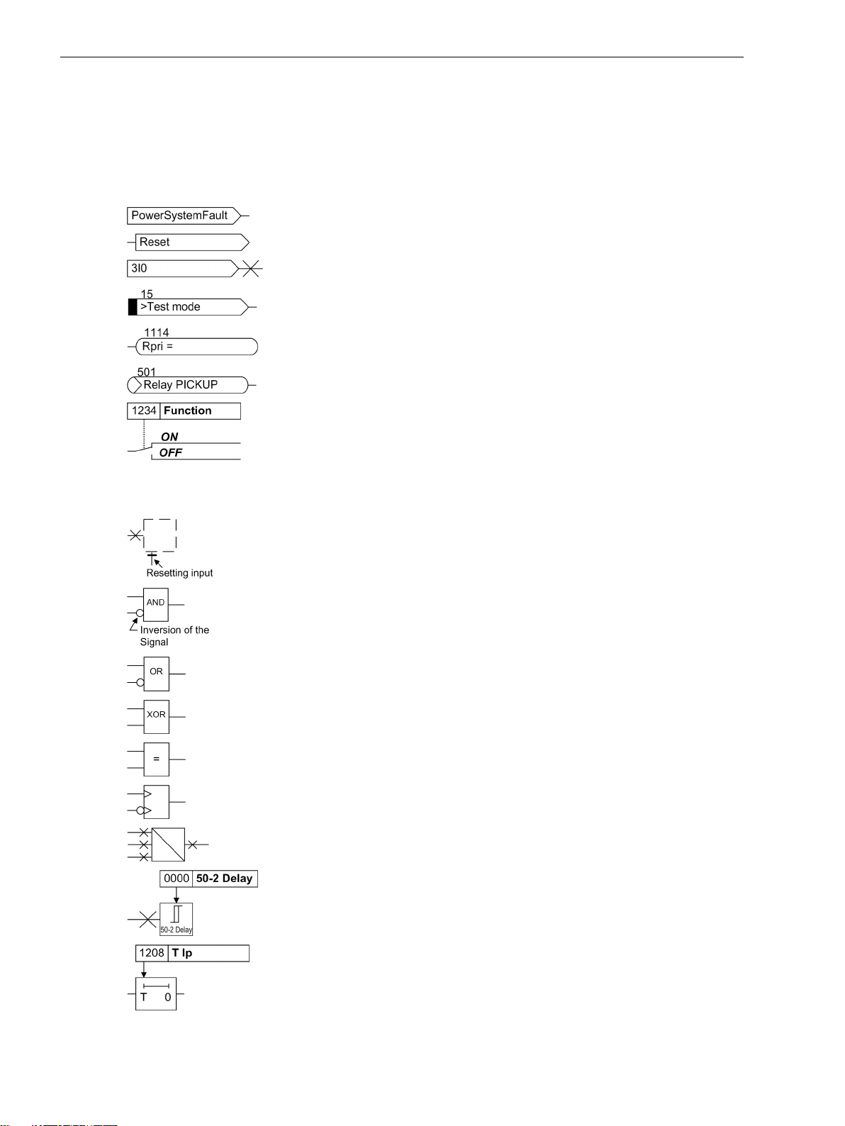
The following symbols are used in drawings:
Device-internal logical input signal
Device-internal logical output signal
Internal input signal of an analog quantity
External binary input signal with number (binary input,
input indication)
External binary output signal with number
(example of a value indication)
External binary output signal with number (device indication) used as
input signal
Example of a parameter switch designated FUNCTION with address
1234 and the possible settings ON and OFF
Besides these, graphical symbols are used in accordance with IEC 60617-12 and IEC 60617-13 or similar.
Some of the most frequently used are listed below:
Analog input variable
AND-gate operation of input values
OR-gate operation of input values
Exclusive OR gate (antivalence): output is active, if only one of the
inputs is active
Coincidence gate: output is active, if both inputs are active or inactive
at the same time
Dynamic inputs (edge-triggered) above with positive, below with
negative edge
Formation of one analog output signal from a number of analog input
signals
Limit stage with setting address and parameter designator (name)
Timer (pickup delay T, example adjustable) with setting address and
parameter designator (name)
6 SIPROTEC 4, 7SJ80, Manual
E50417-G1140-C343-A8, Edition 12.2017
Page 7

Timer (dropout delay T, example non-adjustable)
Dynamic triggered pulse timer T (monoflop)
Static memory (SR flipflop) with setting input (S), resetting input (R),
output (Q) and inverted output (Q), setting input dominant
Static memory (RS-flipflop) with setting input (S), resetting input (R),
output (Q) and inverted output (Q), resetting input dominant
Preface
SIPROTEC 4, 7SJ80, Manual 7
E50417-G1140-C343-A8, Edition 12.2017
Page 8

8 SIPROTEC 4, 7SJ80, Manual
E50417-G1140-C343-A8, Edition 12.2017
Page 9

Open Source Software
The product contains, among other things, Open Source Software developed by third parties. The Open
Source Software used in the product and the license agreements concerning this software can be found in the
Readme_OSS. These Open Source Software files are protected by copyright. Your compliance with those
license conditions will entitle you to use the Open Source Software as foreseen in the relevant license. In the
event of conflicts between Siemens license conditions and the Open Source Software license conditions, the
Open Source Software conditions shall prevail with respect to the Open Source Software portions of the software. The Open Source Software is licensed royalty-free. Insofar as the applicable Open Source Software
License Conditions provide for it you can order the source code of the Open Source Software from your
Siemens sales contact - against payment of the shipping and handling charges - for a period of at least 3 years
since purchase of the Product. We are liable for the Product including the Open Source Software contained in
it pursuant to the license conditions applicable to the Product. Any liability for the Open Source Software
beyond the program flow intended for the Product is explicitly excluded. Furthermore any liability for defects
resulting from modifications to the Open Source Software by you or third parties is excluded. We do not
provide any technical support for the Product if it has been modified.
SIPROTEC 4, 7SJ80, Manual
E50417-G1140-C343-A8, Edition 12.2017
9
Page 10

10 SIPROTEC 4, 7SJ80, Manual
E50417-G1140-C343-A8, Edition 12.2017
Page 11

Table of Contents
Preface..........................................................................................................................................................3
Open Source Software..................................................................................................................................9
1 Introduction................................................................................................................................................19
1.1 Overall Operation..............................................................................................................20
1.2 Application Scope............................................................................................................. 22
1.3 Characteristics.................................................................................................................. 24
2 Functions.................................................................................................................................................... 29
2.1 General.............................................................................................................................30
2.1.1 Functional Scope......................................................................................................... 30
2.1.1.1 Functional Description........................................................................................... 30
2.1.1.2 Setting Notes......................................................................................................... 30
2.1.1.3 Settings................................................................................................................. 32
2.1.2 Device, General Settings.............................................................................................. 34
2.1.2.1 Functional Description........................................................................................... 34
2.1.2.2 Setting Notes......................................................................................................... 34
2.1.2.3 Settings................................................................................................................. 35
2.1.2.4 Information List..................................................................................................... 36
2.1.3 Power System Data 1...................................................................................................37
2.1.3.1 Functional Description........................................................................................... 37
2.1.3.2 Setting Notes......................................................................................................... 38
2.1.3.3 Settings................................................................................................................. 43
2.1.3.4 Information List..................................................................................................... 46
2.1.4 Oscillographic Fault Records........................................................................................ 46
2.1.4.1 Functional Description........................................................................................... 47
2.1.4.2 Setting Notes......................................................................................................... 48
2.1.4.3 Settings................................................................................................................. 48
2.1.4.4 Information List..................................................................................................... 48
2.1.5 Settings Groups........................................................................................................... 49
2.1.5.1 Functional Description........................................................................................... 49
2.1.5.2 Setting Notes......................................................................................................... 49
2.1.5.3 Settings................................................................................................................. 49
2.1.5.4 Information List..................................................................................................... 49
2.1.6 Power System Data 2...................................................................................................50
2.1.6.1 Functional Description........................................................................................... 50
2.1.6.2 Setting Notes......................................................................................................... 50
2.1.6.3 Settings................................................................................................................. 53
2.1.6.4 Information List..................................................................................................... 54
2.1.7 EN100-Module............................................................................................................ 55
2.1.7.1 Functional Description........................................................................................... 55
2.1.7.2 Setting Notes......................................................................................................... 55
2.1.7.3 Information List..................................................................................................... 55
SIPROTEC 4, 7SJ80, Manual 11
E50417-G1140-C343-A8, Edition 12.2017
Page 12

Table of Contents
2.2 Overcurrent Protection 50, 51, 50N, 51N.......................................................................... 56
2.2.1 General ...................................................................................................................... 56
2.2.2 Definite Time, High-set Elements 50-3, 50-2, 50N-3, 50N-2..........................................57
2.2.3 Definite Time Overcurrent Elements 50-1, 50N-1......................................................... 59
2.2.4 Inverse Time Overcurrent Elements 51, 51N ................................................................62
2.2.5 Inverse Time Overcurrent Protection 51V (Voltage-controlled / Voltagerestraint)...........65
2.2.6 Dynamic Cold Load Pickup Function.............................................................................67
2.2.7 Inrush Restraint .......................................................................................................... 68
2.2.8 Pickup Logic and Tripping Logic................................................................................... 69
2.2.9 Two-phase Overcurrent Protection (Only Non-Directional) ...........................................70
2.2.10 Fast Busbar Protection Using Reverse Interlocking ....................................................... 71
2.2.11 Setting Notes...............................................................................................................72
2.2.12 Settings.......................................................................................................................77
2.2.13 Information List...........................................................................................................79
2.3 Directional Overcurrent Protection 67, 67N....................................................................... 82
2.3.1 General....................................................................................................................... 82
2.3.2 Definite Time Directional High-set Elements 67-2, 67N-2, 67-3, 67N-3......................... 84
2.3.3 Definite Time, Directional Time Overcurrent Elements 67-1, 67N-1...............................85
2.3.4 Inverse Time, Directional Overcurrent Elements 67-TOC, 67N-TOC............................... 88
2.3.5 Interaction with Fuse Failure Monitor (FFM).................................................................89
2.3.6 Dynamic Cold Load Pickup Function.............................................................................90
2.3.7 Inrush Restraint........................................................................................................... 90
2.3.8 Determination of Direction.......................................................................................... 90
2.3.9 Reverse Interlocking for Double End Fed Lines..............................................................94
2.3.10 Setting Notes...............................................................................................................95
2.3.11 Settings.....................................................................................................................101
2.3.12 Information List.........................................................................................................104
2.4 Dynamic Cold Load Pickup...............................................................................................106
2.4.1 Functional Description...............................................................................................106
2.4.2 Setting Notes.............................................................................................................108
2.4.3 Settings.....................................................................................................................109
2.4.4 Information List.........................................................................................................111
2.5 Single-Phase Overcurrent Protection................................................................................112
2.5.1 Functional Description...............................................................................................112
2.5.2 High-impedance Ground Fault Unit Protection........................................................... 113
2.5.3 Tank Leakage Protection............................................................................................115
2.5.4 Setting Notes.............................................................................................................116
2.5.5 Settings.....................................................................................................................121
2.5.6 Information List.........................................................................................................121
2.6 Voltage Protection 27, 59................................................................................................122
2.6.1 Measurement Principle.............................................................................................. 122
2.6.2 Overvoltage Protection 59......................................................................................... 123
2.6.3 Undervoltage Protection 27....................................................................................... 124
2.6.4 Setting Notes.............................................................................................................127
2.6.5 Settings.....................................................................................................................130
2.6.6 Information List.........................................................................................................131
12 SIPROTEC 4, 7SJ80, Manual
E50417-G1140-C343-A8, Edition 12.2017
Page 13

Table of Contents
2.7 Negative Sequence Protection 46....................................................................................132
2.7.1 Definite Time characteristic .......................................................................................132
2.7.2 Inverse Time characteristic.........................................................................................132
2.7.3 Setting Notes.............................................................................................................135
2.7.4 Settings.....................................................................................................................136
2.7.5 Information List.........................................................................................................137
2.8 Frequency Protection 81 O/U...........................................................................................138
2.8.1 Functional Description...............................................................................................138
2.8.2 Setting Notes.............................................................................................................139
2.8.3 Settings.....................................................................................................................140
2.8.4 Information List.........................................................................................................141
2.9 Undervoltage-controlled reactive power protection (27/Q)...............................................142
2.9.1 Functional Description...............................................................................................142
2.9.2 Setting Notes.............................................................................................................144
2.9.3 Settings.....................................................................................................................145
2.9.4 Information List.........................................................................................................146
2.10 Thermal Overload Protection 49...................................................................................... 147
2.10.1 Functional Description...............................................................................................147
2.10.2 Setting Notes.............................................................................................................149
2.10.3 Settings.....................................................................................................................152
2.10.4 Information List.........................................................................................................152
2.11 Monitoring Functions......................................................................................................154
2.11.1 Measurement Supervision......................................................................................... 154
2.11.1.1 General................................................................................................................154
2.11.1.2 Hardware Monitoring .......................................................................................... 154
2.11.1.3 Software Monitoring ........................................................................................... 156
2.11.1.4 Monitoring of the Transformer Circuits................................................................. 157
2.11.1.5 Measurement Voltage Failure Detection............................................................... 158
2.11.1.6 Broken Wire Monitoring of Voltage Transformer Circuits....................................... 162
2.11.1.7 Setting Notes....................................................................................................... 163
2.11.1.8 Settings............................................................................................................... 164
2.11.1.9 Information List................................................................................................... 165
2.11.2 Trip Circuit Supervision 74TC..................................................................................... 166
2.11.2.1 Functional Description......................................................................................... 166
2.11.2.2 Setting Notes....................................................................................................... 169
2.11.2.3 Settings............................................................................................................... 169
2.11.2.4 Information List................................................................................................... 170
2.11.3 Malfunction Responses of the Monitoring Functions.................................................. 170
2.11.3.1 Description.......................................................................................................... 170
2.12 Ground Fault Protection 64, 67N(s), 50N(s), 51N(s).........................................................172
2.12.1 Ground Fault Detection for cos-ϕ / sin-ϕ Measurement (Standard Method)..................172
2.12.2 Ground Fault Detection for V0/I0-ϕ Measurement.......................................................178
2.12.3 Extended Ground Fault Protection EPTR/TNP.............................................................. 182
2.12.3.1 General Information.............................................................................................182
2.12.3.2 Ground-Fault Protection EPTR - B.......................................................................... 183
2.12.3.3 Transformer Neutral-Point Protection TNP.............................................................184
2.12.4 Ground Fault Location............................................................................................... 184
2.12.5 Setting Notes.............................................................................................................185
2.12.6 Settings.....................................................................................................................193
2.12.7 Settings EPTR, TNP.....................................................................................................195
SIPROTEC 4, 7SJ80, Manual 13
E50417-G1140-C343-A8, Edition 12.2017
Page 14

Table of Contents
2.12.8 Information List.........................................................................................................195
2.12.9 Information List EPTR, TNP......................................................................................... 196
2.13 Intermittent Ground Fault Protection...............................................................................198
2.13.1 Functional Description...............................................................................................198
2.13.2 Setting Notes.............................................................................................................201
2.13.3 Settings.....................................................................................................................202
2.13.4 Information List.........................................................................................................203
2.14 Dir. Intermittent earth fault protection............................................................................ 204
2.14.1 Functional Description...............................................................................................204
2.14.2 Setting Notes.............................................................................................................207
2.14.3 Settings.....................................................................................................................208
2.14.4 Information List.........................................................................................................208
2.15 Automatic Reclosing System 79.......................................................................................209
2.15.1 Program Execution.................................................................................................... 209
2.15.2 Blocking.................................................................................................................... 213
2.15.3 Status Recognition and Monitoring of the Circuit Breaker........................................... 215
2.15.4 Controlling Protection Elements.................................................................................216
2.15.5 Zone Sequencing / Fuse Saving Scheme..................................................................... 218
2.15.6 Setting Notes.............................................................................................................219
2.15.7 Settings.....................................................................................................................224
2.15.8 Information List.........................................................................................................230
2.16 Fault Locator...................................................................................................................232
2.16.1 Functional Description...............................................................................................232
2.16.2 Setting Notes.............................................................................................................233
2.16.3 Settings.....................................................................................................................234
2.16.4 Information List.........................................................................................................234
2.17 Breaker Failure Protection 50BF.......................................................................................235
2.17.1 Functional Description...............................................................................................235
2.17.2 Setting Notes.............................................................................................................238
2.17.3 Settings.....................................................................................................................240
2.17.4 Information List.........................................................................................................241
2.18 Flexible Protection Functions...........................................................................................242
2.18.1 Functional Description...............................................................................................242
2.18.2 Setting Notes.............................................................................................................246
2.18.3 Settings.....................................................................................................................250
2.18.4 Information List.........................................................................................................252
2.19 Reverse-Power Protection Application with Flexible Protection Function...........................253
2.19.1 Functional Description...............................................................................................253
2.19.2 Implementation of the Reverse Power Protection....................................................... 256
2.19.3 Configuring the Reverse Power Protection in DIGSI.....................................................258
2.20 Synchrocheck................................................................................................................. 261
2.20.1 General..................................................................................................................... 261
2.20.2 Functional Sequence................................................................................................. 263
2.20.3 De-energized Switching.............................................................................................264
2.20.4 Direct Command / Blocking........................................................................................265
2.20.5 Interaction with Control, Automatic Reclosing and External Control............................265
14 SIPROTEC 4, 7SJ80, Manual
E50417-G1140-C343-A8, Edition 12.2017
Page 15

Table of Contents
2.20.6 Setting Notes.............................................................................................................267
2.20.7 Settings.....................................................................................................................271
2.20.8 Information List.........................................................................................................272
2.21 Phase Rotation................................................................................................................ 274
2.21.1 Functional Description...............................................................................................274
2.21.2 Setting Notes.............................................................................................................274
2.22 Function Logic................................................................................................................ 275
2.22.1 Pickup Logic of the Entire Device................................................................................275
2.22.2 Tripping Logic of the Entire Device.............................................................................275
2.22.3 Setting Notes.............................................................................................................276
2.23 Auxiliary Functions..........................................................................................................277
2.23.1 Message Processing...................................................................................................277
2.23.1.1 LED Displays and Binary Outputs (Output Relays)..................................................277
2.23.1.2 Information on the Integrated Display (LCD) or Personal Computer....................... 277
2.23.1.3 Information to a Control Center............................................................................279
2.23.2 Statistics....................................................................................................................279
2.23.2.1 Functional Description......................................................................................... 279
2.23.2.2 Circuit Breaker Maintenance.................................................................................280
2.23.2.3 Setting Notes....................................................................................................... 286
2.23.2.4 Information List................................................................................................... 288
2.23.3 Measurement............................................................................................................288
2.23.3.1 Display of Measured Values.................................................................................. 289
2.23.3.2 Transfer of Measured Values................................................................................ 290
2.23.3.3 Information List................................................................................................... 291
2.23.4 Average Measurements............................................................................................. 292
2.23.4.1 Functional Description......................................................................................... 292
2.23.4.2 Setting Notes....................................................................................................... 292
2.23.4.3 Settings............................................................................................................... 293
2.23.4.4 Information List................................................................................................... 293
2.23.5 Min/Max Measurement Setup.................................................................................... 293
2.23.5.1 Functional Description......................................................................................... 293
2.23.5.2 Setting Notes....................................................................................................... 293
2.23.5.3 Settings............................................................................................................... 294
2.23.5.4 Information List................................................................................................... 294
2.23.6 Set Points for Measured Values.................................................................................. 295
2.23.6.1 Setting Notes....................................................................................................... 296
2.23.7 Set Points for Statistic................................................................................................ 296
2.23.7.1 Functional Description......................................................................................... 296
2.23.7.2 Setting Notes....................................................................................................... 296
2.23.7.3 Information List................................................................................................... 296
2.23.8 Energy Metering........................................................................................................296
2.23.8.1 Functional Description......................................................................................... 297
2.23.8.2 Setting Notes....................................................................................................... 297
2.23.8.3 Settings............................................................................................................... 297
2.23.8.4 Information List................................................................................................... 297
2.23.9 Commissioning Aids.................................................................................................. 297
2.23.9.1 Functional Description......................................................................................... 298
2.24 Breaker Control...............................................................................................................299
2.24.1 Control Device...........................................................................................................299
2.24.1.1 Functional Description......................................................................................... 299
2.24.1.2 Information List................................................................................................... 300
SIPROTEC 4, 7SJ80, Manual 15
E50417-G1140-C343-A8, Edition 12.2017
Page 16

Table of Contents
2.24.2 Types of Commands.................................................................................................. 300
2.24.2.1 Functional Description......................................................................................... 300
2.24.3 Command Sequence..................................................................................................300
2.24.3.1 Functional Description......................................................................................... 301
2.24.4 Interlocking............................................................................................................... 301
2.24.4.1 Functional Description......................................................................................... 301
2.24.5 Command Logging.................................................................................................... 308
2.24.5.1 Functional Description......................................................................................... 308
2.25 Notes on Device Operation..............................................................................................309
2.25.1 Different operation....................................................................................................309
3 Mounting and Commissioning................................................................................................................. 311
3.1 Mounting and Connections............................................................................................. 312
3.1.1 Configuration Information......................................................................................... 312
3.1.2 Hardware Modifications.............................................................................................315
3.1.2.1 Disassembly.........................................................................................................315
3.1.2.2 Connections of the Current Terminals...................................................................318
3.1.2.3 Connections of the Voltage Terminals...................................................................319
3.1.2.4 Interface Modules................................................................................................ 320
3.1.2.5 Reassembly..........................................................................................................322
3.1.3 Installation................................................................................................................ 323
3.1.3.1 General................................................................................................................323
3.1.3.2 Panel Flush Mounting...........................................................................................324
3.1.3.3 Cubicle Mounting.................................................................................................325
3.1.3.4 Panel Surface Mounting....................................................................................... 326
3.2 Checking Connections.....................................................................................................328
3.2.1 Checking the Data Connections of the Interfaces........................................................328
3.2.2 Checking the System Connections............................................................................. 330
3.3 Commissioning............................................................................................................... 332
3.3.1 Test Mode and Transmission Block.............................................................................333
3.3.2 Testing the System Interface (at Port B) .....................................................................333
3.3.3 Configuring Communication Modules........................................................................334
3.3.4 Checking the Status of Binary Inputs and Outputs...................................................... 338
3.3.5 Tests for Breaker Failure Protection............................................................................ 340
3.3.6 Testing User-Defined Functions..................................................................................342
3.3.7 Current, Voltage, and Phase Rotation Testing............................................................. 342
3.3.8 Test for High Impedance Protection........................................................................... 343
3.3.9 Testing the Reverse Interlocking Scheme....................................................................343
3.3.10 Direction Check with Load Current.............................................................................344
3.3.11 Polarity Check for Voltage Input V3.............................................................................345
3.3.12 Ground Fault Check................................................................................................... 347
3.3.13
Polarity Check for Current Input ΙE..............................................................................347
3.3.14 Trip/Close Tests for the Configured Operating Devices................................................ 350
3.3.15 Creating Oscillographic Recordings for Tests.............................................................. 350
3.4 Final Preparation of the Device........................................................................................352
4 Technical Data.......................................................................................................................................... 353
4.1 General Device Data........................................................................................................354
4.1.1 Analog Inputs............................................................................................................354
4.1.2 Auxiliary voltage........................................................................................................354
16 SIPROTEC 4, 7SJ80, Manual
E50417-G1140-C343-A8, Edition 12.2017
Page 17

Table of Contents
4.1.3 Binary Inputs and Outputs......................................................................................... 355
4.1.4 Communication Interfaces.........................................................................................356
4.1.5 Electrical Tests...........................................................................................................358
4.1.6 Mechanical Tests....................................................................................................... 360
4.1.7 Climatic Stress Tests.................................................................................................. 360
4.1.8 Service Conditions..................................................................................................... 361
4.1.9 Constructive Design...................................................................................................361
4.1.10 UL certification conditions......................................................................................... 362
4.2 Definite-time Overcurrent Protection...............................................................................363
4.3 Inverse-time Overcurrent Protection................................................................................365
4.4 Directional Overcurrent Protection.................................................................................. 376
4.5 Inrush Restraint...............................................................................................................378
4.6 Dynamic Cold Load Pickup...............................................................................................379
4.7 1-phase Overcurrent Protection.......................................................................................380
4.8 Voltage Protection.......................................................................................................... 381
4.9 Negative Sequence Protection (definite-time characteristic).............................................383
4.10 Negative Sequence Protection (inverse-time characteristics)............................................384
4.11 Frequency Protection 81 O/U...........................................................................................390
4.12 Undervoltage-controlled reactive power protection (27/Q)...............................................391
4.13 Thermal Overload Protection...........................................................................................393
4.14 Ground Fault Detection (Sensitive/Insensitive).................................................................395
4.15 Intermittent Ground Fault Protection...............................................................................401
4.16 Directional intermittent ground fault protection.............................................................. 402
4.17 Automatic Reclosing....................................................................................................... 403
4.18 Fault Locator...................................................................................................................404
4.19 Breaker Failure Protection 50BF ...................................................................................... 405
4.20 Flexible Protection Functions ..........................................................................................406
4.21 Synchrocheck 25 ............................................................................................................409
4.22 User-defined Functions (CFC).......................................................................................... 411
4.23 Auxiliary Functions..........................................................................................................416
4.24 Switching Device Control................................................................................................ 421
4.25 Dimensions.....................................................................................................................422
4.25.1 Panel Flush and Cubicle Mounting (Housing Size 1/6) ................................................422
4.25.2 Panel Surface Mounting (Housing Size 1/6) ............................................................... 423
4.25.3 Bottom view..............................................................................................................423
4.25.4 Varistor..................................................................................................................... 424
A Ordering Information and Accessories.....................................................................................................425
A.1 Ordering Information 7SJ80 ........................................................................................... 426
A.2 Accessories.....................................................................................................................431
B Terminal Assignments..............................................................................................................................433
B.1 7SJ80 — Housing for panel flush mounting and cubicle installation and for panel
surface mounting ...........................................................................................................434
C Connection Examples............................................................................................................................... 441
C.1 Connection Examples for Current and Voltage Transformers............................................442
SIPROTEC 4, 7SJ80, Manual 17
E50417-G1140-C343-A8, Edition 12.2017
Page 18

Table of Contents
C.2 Connection Examples for SICAM I/O Units........................................................................454
D Current Transformer Requirements......................................................................................................... 455
D.1 Accuracy limiting factors................................................................................................. 456
D.2 Class conversion............................................................................................................. 457
D.3 Cable core balance current transformer........................................................................... 458
E Default Settings and Protocol-dependent Functions............................................................................... 459
E.1 LEDs............................................................................................................................... 460
E.2 Binary Input.................................................................................................................... 462
E.3 Binary Output................................................................................................................. 463
E.4 Function Keys................................................................................................................. 464
E.5 Default Display................................................................................................................465
E.6 Protocol-dependent Functions.........................................................................................468
F Functions, Settings, Information..............................................................................................................469
F.1 Functional Scope............................................................................................................ 470
F.2 Settings.......................................................................................................................... 472
F.3 Information List.............................................................................................................. 501
F.4 Group Alarms..................................................................................................................539
F.5 Measured Values.............................................................................................................541
Literature.................................................................................................................................................. 547
Glossary.................................................................................................................................................... 549
Index.........................................................................................................................................................559
18 SIPROTEC 4, 7SJ80, Manual
E50417-G1140-C343-A8, Edition 12.2017
Page 19

1
Introduction
The device family SIPROTEC 7SJ80 devices is introduced in this section. An overview of the devices is
presented in their application, characteristics, and scope of functions.
1.1 Overall Operation 20
1.2 Application Scope 22
1.3 Characteristics 24
SIPROTEC 4, 7SJ80, Manual 19
E50417-G1140-C343-A8, Edition 12.2017
Page 20
Introduction
1.1 Overall Operation
1.1
Analog Inputs
Overall Operation
The digital SIPROTEC 7SJ80 overcurrent protection is equipped with a powerful microprocessor. It allows all
tasks to be processed digitally, from the acquisition of measured quantities to sending commands to circuit
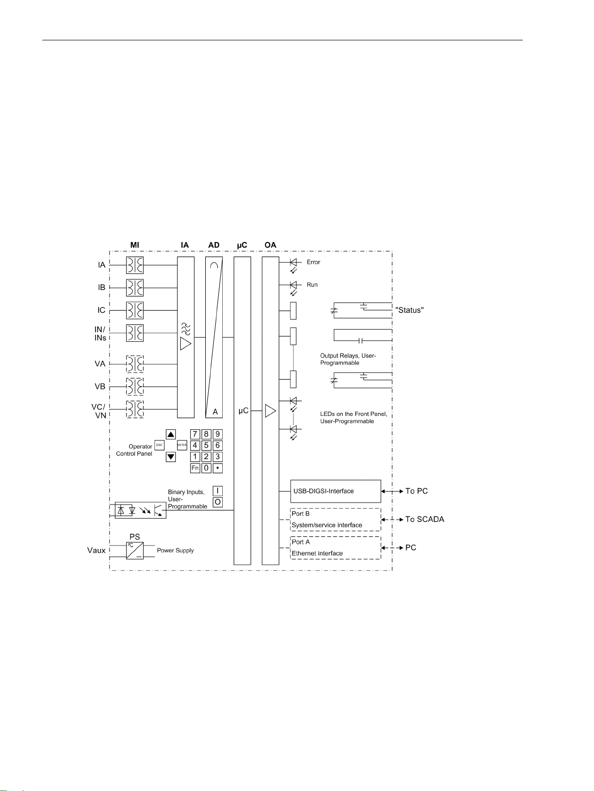
breakers. Figure 1-1 shows the basic structure of the 7SJ80.
The measuring inputs (MI) convert the currents and voltages coming from the measuring transformers and
adapt them to the level appropriate for the internal processing of the device. The device provides 4 current
transformers and - depending on the model - additionally 3 voltage transformers. Three current inputs serve
for the input of the phase currents, another current input (ΙN) may be used for measuring the ground fault
current ΙN (current transformer neutral point) or for a separate ground current transformer (for sensitive
ground fault detection ΙNs and directional determination of ground faults ) - depending on the model.
[hw-struktur-7sj80-060606, 1, en_US]
Figure 1-1
The optional voltage transformers can either be used to input 3 phase-to-ground voltages or 2 phase-to-phase
voltages and the displacement voltage (open delta voltage) or any other voltages. It is also possible to connect
two phase-to-phase voltages in open delta connection.
The analog input quantities are passed on to the input amplifiers (IA). The input amplifier IA element provides
a high-resistance termination for the input quantities. It consists of filters that are optimized for measuredvalue processing with regard to bandwidth and processing speed.
The analog-to-digital (AD) transformer group consists of an analog-to-digital converter and memory components for the transmission of data to the microcomputer.
20 SIPROTEC 4, 7SJ80, Manual
Hardware structure of the digital multi-functional protective relay 7SJ80
E50417-G1140-C343-A8, Edition 12.2017
Page 21

Microcomputer System
Apart from processing the measured values, the microcomputer system (μC) also executes the actual protection and control functions. They especially include:
Filtering and preparation of the measured quantities
•
Continuous monitoring of the measured quantities
•
Monitoring of the pickup conditions for the individual protective functions
•
Interrogation of limit values and sequences in time
•
Control of signals for the logic functions
•
Output of control commands for switching devices
•
Recording of messages, fault data and fault values for analysis
•
Management of the operating system and the associated functions such as data recording, real-time
•
clock, communication, interfaces, etc.
The information is distributed via output amplifiers (OA).
•
Binary Inputs and Outputs
The computer system obtains external information through the binary input/output boards (inputs and
outputs). The computer system obtains information from the system (e.g remote resetting) or from external
equipment (e.g. blocking commands). These outputs include, in particular, trip commands to circuit breakers
and signals for the remote indication of important events and conditions.
Introduction
1.1 Overall Operation
Front Panel
Information such as messages related to events, states, measured values and the functional status of the
device are visualized by light-emitting diodes (LEDs) and a display screen (LCD) on the front panel.
Integrated control and numeric keys in conjunction with the LCD enable interaction with the remote device.
These elements can be used to access the device for information such as configuration and setting parameters. Similarly, setting parameters can be accessed and changed if needed.
In addition, control of circuit breakers and other equipment is possible from the front panel of the device.
Interfaces
Communication with a PC can be implemented via the USB DIGSI interface using the DIGSI software, allowing
all device functions to be easily executed.
Communication with a PC is also possible via port A (Ethernet interface) and port B (System/Service interface)
using DIGSI.
In addition to the device communication via DIGSI, port B can also be used to transmit all device data to a
central evaluator or a control center. This interface may be provided with various protocols and physical transmission schemes to suit the particular application.
Power Supply
A power supply unit (Vaux or PS) delivers power to the functional units using the different voltage levels.
Voltage dips may occur if the voltage supply system (substation battery) becomes short-circuited. Usually,
they are bridged by a capacitor (see also Technical Data).
A buffer battery is located under the flap at the lower end of the front cover.
SIPROTEC 4, 7SJ80, Manual 21
E50417-G1140-C343-A8, Edition 12.2017
Page 22

Introduction
1.2 Application Scope
1.2
Protective Functions
Application Scope
The multi-function numerical overcurrent protection SIPROTEC 4 7SJ80 is used as protection, control and
monitoring unit for busbar feeders. For line protection, the device can be used in networks with grounded,
lowresistance grounded, isolated or a compensated neutral point structure. It is suited for networks that are
radial and supplied from a single source, open or closed looped networks and for lines with sources at both
ends.
The device includes the functions that are usually necessary for protection, monitoring of circuit breaker positions and control of circuit breakers in single and double busbars; therefore, the device can be employed
universally. The device provides excellent backup protection of differential protective schemes of any kind for
lines, transformers and busbars of all voltage levels.
Non-directional overcurrent protection (50, 50N, 51, 51N) is the basic function of the device. There are three
definite time elements and one inverse time element for the phase currents and the ground current. For the
inverse time elements, several characteristics of different standards are provided. Alternatively, a user-defined
characteristic can be used for the sensitive ground fault detection.
Further protection functions included are the negative sequence protection, overload protection, circuit
breaker failure protection and ground fault protection.
Depending on the ordered variant, further protection functions are included, such as frequency protection,
overvoltage and undervoltage protection, and ground fault protection for high-resistance ground faults (directional or non-directional).
Apart from the short circuit protection functions mentioned before, there are further protection functions
possible as order variants. The overcurrent protection can, for example, be supplemented by a directional
overcurrent protection.
The automatic reclosing function enables several different reclosing cycles for overhead lines. An external
automatic reclosing system can also be connected. To ensure quick detection of the fault location after a short
circuit, the device is equipped with a fault locator.
Before reclosing after a three-pole tripping, the device can verify the validity of the reclosure via a voltage
check and/or a synchrocheck. The synchrocheck function can also be controlled externally.
Control Functions
The device provides a control function which can be accomplished for activating and deactivating the switchgear via operator buttons, port B, binary inputs and - using a PC and the DIGSI software - via the front interface.
The status of the primary equipment can be transmitted to the device via auxiliary contacts connected to
binary inputs. The present status (or position) of the primary equipment can be displayed on the device, and
used for interlocking or alarm condition monitoring. The number of operating equipments to be switched is
limited by the binary inputs and outputs available in the device or the binary inputs and outputs allocated for
the switch position indications. Depending on the primary equipment being controlled, one binary input
(single point indication) or two binary inputs (double point indication) may be used for this process.
The capability of switching primary equipment can be restricted by a setting associated with switching
authority (Remote or Local), and by the operating mode (interlocked/non-interlocked, with or without password request).
Processing of interlocking conditions for switching (e.g. switchgear interlocking) can be established with the
aid of integrated, user-configurable logic functions.
Messages and Measured Values; Recording of Event and Fault Data
The operational indications provide information about conditions in the power system and the device. Measurement quantities and values that are calculated can be displayed locally and communicated via the serial
interfaces.
Device messages can be assigned to a number of LEDs on the front cover (allocatable), can be externally
processed via output contacts (allocatable), linked with user-definable logic functions and/or issued via serial
interfaces.
22 SIPROTEC 4, 7SJ80, Manual
E50417-G1140-C343-A8, Edition 12.2017
Page 23

During a fault (system fault) important events and changes in conditions are saved in fault protocols (Event
Log or Trip Log). Instantaneous fault values are also saved in the device and may be analyzed subsequently.
Communication
The following interfaces are available for communication with external operating, control and memory
systems.
The USB DIGSI interface on the front cover serves for local communication with a PC. By means of the
SIPROTEC 4 operating software DIGSI, all operational and evaluation tasks can be executed via this operator
interface, such as specifying and modifying configuration parameters and settings, configuring user-specific
logic functions, retrieving operational messages and measured values, inquiring device conditions and measured values, issuing control commands.
Depending on the ordered variant, additional interfaces are located at the bottom of the device. They serve for
establishing extensive communication with other digital operating, control and memory components:
Port A serves for DIGSI communication directly on the device or via network. Furthermore, 2 SICAM I/O units
7XV5673 can be connected to this port. Port A can also be used for time synchronization using the NTP
protocol.
Port B serves for central communication between the device and a control center. It can be operated via data
lines or fiber optic cables. For the data transfer, there are standard protocols in accordance with IEC 60870-5103 available. The integration of the devices into the SINAUT LSA and SICAM automation systems can also be
implemented with this profile.
Alternatively, additional connection options are available with PROFIBUS DP and the DNP3.0 and MODBUS
protocols. If an EN100 module is available, you can use the protocols IEC61850, PROFINET or DNP3 TCP.
Furthermore, connecting a SICAM I/O unit is possible via IEC651850 GOOSE.
Introduction
1.2 Application Scope
SIPROTEC 4, 7SJ80, Manual 23
E50417-G1140-C343-A8, Edition 12.2017
Page 24

Introduction
1.3 Characteristics
1.3
General Characteristics
Characteristics
Powerful 32-bit microprocessor system
•
Complete digital processing and control of measured values, from the sampling of the analog input quan-
•
tities to the initiation of outputs, for example, tripping or closing circuit breakers or other switchgear
devices
Total electrical separation between the internal processing stages of the device and the external trans-
•
former, control, and DC supply circuits of the system because of the design of the binary inputs, outputs,
and the DC or AC converters
Complete set of functions necessary for the proper protection of lines, feeders, motors, and busbars
•
Easy device operation through an integrated operator panel or by means of a connected personal
•
computer running DIGSI
Continuous calculation and display of measured and metered values on the front of the device
•
Storage of min./max. measured values (slave pointer function) and storage of long-term mean values
•
Recording of event and fault data for the last 8 system faults (fault in a network) with real-time informa-
•
tion as well as instantaneous values for fault recording for a maximum time range of 20 s
Constant monitoring of the measured quantities, as well as continuous self-diagnostics covering the
•
hardware and software
Communication with SCADA or substation controller equipment via serial interfaces through the choice
•
of data cable, modem, or optical fibers
Battery-buffered clock which can be synchronized via a synchronization signal at the binary input or via a
•
protocol
Switching statistics: Counting the number of trip commands initiated by the device, logging the currents
•
of the last switch-off operation initiated by the device, and accumulating the eliminated short-circuit
currents of each breaker pole
Operating hours counter: Counting the operating hours of the protected object under load
•
Commissioning aids such as connection and direction check, status indication of all binary inputs and
•
outputs, easy testing of port B, and influencing of information at port B during test operation.
Time Overcurrent Protection 50, 51, 50N, 51N
Three definite time overcurrent protective elements and one inverse time overcurrent protective element
•
for phase current and ground current ΙN or summation current 3Ι
Two-phase operation of the overcurrent protection (ΙA, ΙC) is possible
•
For inverse-time overcurrent protection, selection from various characteristics of different standards
•
possible
Blocking is possible, e.g. for reverse interlocking with any element
•
Instantaneous tripping by any element is possible when switching onto a fault
•
In-rush restraint with second harmonic current quantities.
•
Ground Fault Protection 50N, 51N
0
Three definite time overcurrent protective elements and one inverse time overcurrent protective element
•
applicable for grounded or high-resistance grounded systems
For inverse-time overcurrent protection, selection from various characteristics of different standards
•
24 SIPROTEC 4, 7SJ80, Manual
E50417-G1140-C343-A8, Edition 12.2017
Page 25

In-rush restraint with second harmonic current quantities
•
Instantaneous tripping by any overcurrent element upon switch onto fault is possible.
•
Directional Time Overcurrent Protection 67, 67N
Three definite time overcurrent protection elements and one inverse time overcurrent protection
•
element for the phase operate in parallel to the non-directional overcurrent elements. Their pickup values
and time delays can be set independently of these.
Direction determination with cross-polarized voltages and voltage memory and dynamically unlimited
•
direction sensitivity
Fault direction is calculated phase-selectively and separately for phase faults, ground faults and summa-
•
tion current faults.
Dynamic Cold Load Pick-up Function 50C, 50NC, 51C, 51NC, 67C, 67NC
Dynamic changeover of time overcurrent protection settings, e.g. when cold load conditions are recog-
•
nized
Detection of cold load condition via circuit breaker position or current threshold
•
Activation via automatic reclosure (AR) is possible
•
Activation also possible via binary input.
•
Introduction
1.3 Characteristics
Single-Phase Overcurrent Protection
Evaluation of the measured current via the sensitive or insensitive ground current transformer
•
Suitable as differential protection that includes the neutral point current on transformer side, generator
•
side or motor side or for a grounded reactor set
As tank leakage protection against abnormal leakage currents between transformer tanks and ground.
•
Voltage Protection 27, 59
Two element undervoltage detection via the positive-sequence system of the voltages, phase-to-phase or
•
phase-to-ground voltages
Choice of current supervision for 27-1 and 27-2
•
Separate two-element overvoltage detection of the largest voltages applied or detection of the positive or
•
negative sequence component of the voltages
Settable dropout ratio for all elements of the undervoltage and overvoltage protection.
•
Negative Sequence Protection 46
Evaluation of the negative sequence component of the currents
•
Two definite-time elements 46-1 and 46-2 and one inverse-time element 46-TOC; curves of common
•
standards are available for 46-TOC.
Frequency Protection 81 O/U
Monitoring of falling below (f<) and/or exceeding (f>) with 4 frequency limits and time delays that are
•
independently adjustable
Insensitive to harmonics and abrupt phase angle changes
•
Adjustable undervoltage threshold.
•
SIPROTEC 4, 7SJ80, Manual 25
E50417-G1140-C343-A8, Edition 12.2017
Page 26

Introduction
1.3 Characteristics
Undervoltage-controlled reactive power protection (27/Q)
Detection of critical power system situations
•
Disconnection of power supply facilities from the grid
•
Reconnection under stable power system conditions
•
Thermal Overload Protection 49
Thermal profile of energy losses (overload protection has full memory capability)
•
True r.m.s. calculation
•
Adjustable thermal warning element
•
Adjustable alarm level based on current magnitude
•
Monitoring Functions
Increased reliability due to monitoring of the internal measurement circuits as well as the hardware and
•
software
Fuse failure monitor with protection function blocking
•
Monitoring of the current transformer and voltage transformer secondary circuits using sum and
•
symmetry supervision with optional protection function blocking
Trip circuit monitoring possible
•
Phase rotation check.
•
Ground Fault Detection 50N(s), 51N(s), 67N(s), 59N/64
Displacement voltage is measured or calculated from the three phase voltages
•
Determination of a faulty phase on ungrounded or grounded systems
•
Two-element Ground Fault Detection: 50Ns-1 and 50Ns-2
•
High sensitivity (as low as 1 mA)
•
Overcurrent element with definite time or inverse time delay
•
For inverse-time overcurrent protection, a user-defined characteristic is available
•
Direction determination with zero sequence quantities(Ι0, V0), wattmetric ground fault direction determi-
•
nation
Any element can be set as directional or non-directional — forward sensing directional, or reverse
•
sensing directional
Optionally applicable as additional ground fault protection.
•
Intermittent Ground Fault Protection
Detects and accumulates intermittent ground faults
•
Tripping after configurable total time.
•
Directional intermittent ground fault protection
Detects intermittent ground faults
•
Direction determination
•
Tripping after settable number of intermittent re-ignitions
•
26 SIPROTEC 4, 7SJ80, Manual
E50417-G1140-C343-A8, Edition 12.2017
Page 27

Automatic Reclosing 79
Single-shot or multi-shot
•
With separate dead times for the first and all succeeding shots
•
Protective elements that initiate automatic reclosing are selectable. The choices can be different for
•
phase faults and ground faults
Separate programs for phase and ground faults
•
Interaction to time overcurrent protection element and ground fault elements. They can be blocked in
•
dependence of the reclosing cycle or released instantaneously
Synchronous reconnection is possible .
•
Fault Location
Initiation by trip command, external command or dropout of pickup
•
Calculation of the fault distance and output of the fault location in ohms (primary and secondary) and in
•
kilometers or miles
Up to three line sections can be configured.
•
Breaker Failure Protection 50 BF
By checking the current and/or evaluating the circuit breaker auxiliary contacts
•
Started by any integrated protection function that trips
•
Initiation possible via a binary input from an external protective device.
•
Introduction
1.3 Characteristics
Flexible Protective Functions
Up to 20 customizable protection functions with three-phase or single-phase operation
•
Any calculated or directly measured quantity can be evaluated on principle
•
Standard protection logic with definite time characteristic
•
Internal and configurable pickup and dropout delay
•
Modifiable message texts.
•
Synchrocheck
Verification of the synchronous conditions before reclosing after three-pole tripping
•
Fast measurement of the voltage difference ΔV, the phase angle difference Δϕ and the frequency differ-
•
ence Δf
Alternatively, check of the de-energized state before reclosing
•
Setable minimum and maximum voltage
•
Verification of the synchronous conditions or de-energized state also possible before the manual closing
•
of the circuit breaker, with separate limit values
Measurement also possible via transformer without external intermediate matching transformer
•
Measuring voltages optionally phase–to–phase or phase–to–ground.
•
Phase Rotation
Selectable ABC or ACB by setting (static) or binary input (dynamic).
•
SIPROTEC 4, 7SJ80, Manual 27
E50417-G1140-C343-A8, Edition 12.2017
Page 28

Introduction
1.3 Characteristics
Circuit-Breaker Maintenance
Statistical methods to help adjust maintenance intervals for CB contacts according to their actual wear
•
several independent subfunctions have been implemented(ΣΙ-procedure, ΣΙx-procedure, 2P-procedure
•
and Ι2t-procedure)
Acquisition and conditioning of measured values for all subfunctions operates phase-selective using one
•
procedure-specific threshold per subfunction.
User Defined Functions
Freely programmable linking of internal and external signals in order to implement user-defined logic
•
functions
All standard logic functions (AND, OR, NOT, EXCLUSIVE-OR, etc.)
•
Time delays and limit value interrogations
•
Processing of measured values, including zero suppression, adding a knee curve for a transducer input,
•
and live-zero monitoring.
Breaker Control
Switching devices can be opened and closed manually using control keys, programmable function keys,
•
via port B (e.g. of SICAM or LSA), or via the user interface (using a personal computer and the DIGSI operating software)
Feedback of switching states via the switch auxiliary contacts
•
Plausibility monitoring of the circuit breaker position and check of interlocking conditions.
•
28 SIPROTEC 4, 7SJ80, Manual
E50417-G1140-C343-A8, Edition 12.2017
Page 29

2
Functions
This chapter describes the numerous functions available on the SIPROTEC 4 device 7SJ80. It shows the setting
possibilities for each function in maximum configuration. Information with regard to the determination of
setting values as well as formulas, if required, are also provided.
Based on the following information, it can also be determined which of the provided functions should be
used.
2.1 General 30
2.2 Overcurrent Protection 50, 51, 50N, 51N 56
2.3 Directional Overcurrent Protection 67, 67N 82
2.4 Dynamic Cold Load Pickup 106
2.5 Single-Phase Overcurrent Protection 112
2.6 Voltage Protection 27, 59 122
2.7 Negative Sequence Protection 46 132
2.8 Frequency Protection 81 O/U 138
2.9 Undervoltage-controlled reactive power protection (27/Q) 142
2.10 Thermal Overload Protection 49 147
2.11 Monitoring Functions 154
2.12 Ground Fault Protection 64, 67N(s), 50N(s), 51N(s) 172
2.13 Intermittent Ground Fault Protection 198
2.14 Dir. Intermittent earth fault protection 204
2.15 Automatic Reclosing System 79 209
2.16 Fault Locator 232
2.17 Breaker Failure Protection 50BF 235
2.18 Flexible Protection Functions 242
2.19 Reverse-Power Protection Application with Flexible Protection Function 253
2.20 Synchrocheck 261
2.21 Phase Rotation 274
2.22 Function Logic 275
2.23 Auxiliary Functions 277
2.24 Breaker Control 299
2.25 Notes on Device Operation 309
SIPROTEC 4, 7SJ80, Manual 29
E50417-G1140-C343-A8, Edition 12.2017
Page 30

i
i
Functions
2.1 General
2.1
2.1.1
2.1.1.1
Setting the Functional Scope
General
The settings associated with the various device functions can be modified using the operating or service interface in DIGSI in conjunction with a personal computer. Some parameters can also be changed using the
controls on the front panel of the device. The procedure is described in detail in the SIPROTEC System Description /1/ SIPROTEC 4 System Description.
Functional Scope
The 7SJ80 relay contains protection functions as well as auxiliary functions. The hardware and firmware is
designed for this scope of functions. Additionally, the control functions can be matched to the system requirements. Individual functions can be enabled or disabled during the configuration procedure. The interaction of
functions may also be modified.
Functional Description
Example for the configuration of the functional scope:
A protected system consists of overhead lines and underground cables. Since automatic reclosing is only
needed for the overhead lines, the automatic reclosing function is not configured or “disabled” for the relays
protecting the underground cables.
The available protection and additional functions can be configured as Enabled or Disabled. For individual
functions, a choice between several alternatives may be possible, as described below.
Functions configured as Disabled are not processed by the 7SJ80. There are no messages and corresponding
settings (functions, limit values) queried during configuration.
NOTE
Available functions and default settings are depending on the order variant of the relay (see A Ordering
Information and Accessories).
2.1.1.2
Setting the Functional Scope
Special Features
Setting Notes
Your protection device is configured using the DIGSI software. Connect your personal computer either to the
USB port on the device front or to port A or port B on the bottom side of the device depending on the device
version (ordering code). The operation via DIGSI is explained in the SIPROTEC 4 System Description.
The Device Configuration dialog box allows you to adjust your device to the specific system conditions.
Password no. 7 is required (for parameter set) for changing configuration parameters in the device. Without
the password the settings can only be read but not edited and transmitted to the device.
Most settings are self-explanatory. The special cases are described in the following.
If you want to use the setting group change function, set address 103 Grp Chge OPTION to Enabled. In
this case, you can select up to four different groups of function parameters between which you can switch
quickly and conveniently during operation. Only one setting group can be used when selecting the option
Disabled.
For the elements associated with non-directional overcurrent protection 50(N), 51(N) (phase and ground),
various tripping characteristics can be selected at addresses 112 Charac. Phase and 113 Charac.
Ground. If only the definite time characteristic is desired, select Definite Time. Alternatively, you can
select between inverse-time curves according to IEC standard (TOC IEC) or ANSI standard (TOC ANSI). The
dropout behavior of the IEC and ANSI curves is specified at address 1210 or 1310 when configuring the time
overcurrent protection.
30 SIPROTEC 4, 7SJ80, Manual
E50417-G1140-C343-A8, Edition 12.2017
Page 31

Functions
2.1 General
Set to Disabled to disable the entire time overcurrent protection.
The directional overcurrent protection 67(N) is set at address 115 67/67-TOC and 116 67N/67N-TOC. Here,
the same options are available as for non-directional overcurrent protection (except the 50-3 element).
For (sensitive) ground fault detection address 130 S.Gnd.F.Dir.Ch lets you specify the directional charac-
teristic of the sensitive ground fault detection. You can select between cos φ / sin φ and V0/I0 φ mea.
as the measurement procedure. The cos φ / sin φ procedure (via residual wattmetric current detection) is
set by default.
If the measuring method cos φ / sin φ is set, select between a definite time characteristic (Definite
Time) and an inverse time characteristic User Defined PU at address 131 Sens. Gnd Fault. V0/I0 φ
mea. provides the definite time characteristic Definite Time, inverse time characteristics TOC IEC or TOC
ANSI. When selecting the setting Disabled, the entire function is disabled.
For the intermittent ground fault protection, you can specify the measured quantity (with Ignd, with 3I0
or with Ignd,sens.) to be used by this protection function at address 133 INTERM.EF.
At address 134 Dir. Interm. EF you can set the directional intermittent ground fault protection to
Enabled or Disabled.
For unbalanced load protection, address 140 46 allows you to specify which tripping characteristics to use.
You can select between Definite Time, TOC ANSI or TOC IEC. If this function is not required, select
Disabled.
The overload protection is activated in address 142 49 by selecting the setting without ambient temperature
No ambient temp or it is set to Disabled.
At address 155 27/Q-Protection you can set the QU protection to Enabled or Disabled.
The synchronization function is activated in address 161 25 Function 1 by the setting SYNCHROCHECK or it
is set to Disabled.
In address 170 you can set the breaker failure protection to Enabled or Disabled. The setting option
enabled w/ 3I0> subjects the ground current and the negative sequence current to a plausibility check.
For the CB maintenance functions, several options are available under address 172 52 B.WEAR MONIT. Irre-
spective of this, the basic functionality of the summation current formation (ΣΙ procedure) is always active. It
requires no further configurations and adds up the tripping currents of the trips initiated by the protection
functions.
When selecting the ΣIx-Procedure, the sum of all tripping current powers is formed and output as reference
value. The 2P Procedure continuously calculates the remaining lifespan of the circuit breaker.
With the Ι2t Procedure the square fault current integrals are formed via arc time and output as a reference
value.
Further information concerning the individual procedures of the CB maintenance are given in
Section2.23.2 Statistics. You can also disable this function by setting it to Disabled.
In address 181, you can enter how many line sections (maximum of three) are taken into account by the fault
locator.
Under address 182 74 Trip Ct Supv it can be selected whether the trip-circuit supervision works with two
(2 Binary Inputs) or only one binary input (1 Binary Input), or whether the function is configured
Disabled.
In address 617 ServiProt (CM) you can specify for which purpose port B is used. T103 means that the
device is connected to a control and protection facility via serial port, DIGSI means that you are using the
port to connect DIGSI or you are not using port B (Disabled).
The flexible protection functions can be configured via parameter FLEXIBLE FUNC.. You can create up to 20
flexible functions by setting a checkmark in front of the desired function (an example is given in the Section
2.19 Reverse-Power Protection Application with Flexible Protection Function). If the checkmark of a function is
removed, all settings and configurations made previously will be lost. After re-selecting the function, all
settings and configurations are in default setting. Setting of the flexible function is done in DIGSI under
“Parameters”, “Additional Functions” and “Settings”. The configuration is done, as usual, under “Parameters”
and “Masking I/O (Configuration Matrix)”.
SIPROTEC 4, 7SJ80, Manual 31
E50417-G1140-C343-A8, Edition 12.2017
Page 32

Functions
2.1 General
2.1.1.3
Settings
Addr. Parameter Setting Options Default Setting Comments
103 Grp Chge OPTION Disabled
Disabled Setting Group Change Option
Enabled
104 OSC. FAULT REC. Disabled
Enabled Oscillographic Fault Records
Enabled
112 Charac. Phase Disabled
Definite Time 50/51
Definite Time
TOC IEC
TOC ANSI
113 Charac. Ground Disabled
Definite Time 50N/51N
Definite Time
TOC IEC
TOC ANSI
115 67/67-TOC Disabled
Definite Time 67, 67-TOC
Definite Time
TOC IEC
TOC ANSI
116 67N/67N-TOC Disabled
Definite Time 67N, 67N-TOC
Definite Time
TOC IEC
TOC ANSI
117 Coldload Pickup Disabled
Disabled Cold Load Pickup
Enabled
122 InrushRestraint Disabled
Disabled 2nd Harmonic Inrush Restraint
Enabled
127 50 1Ph Disabled
Disabled 50 1Ph
Enabled
130 S.Gnd.F.Dir.Ch cos φ / sin φ
V0/I0 φ mea.
131 Sens. Gnd Fault Disabled
cos φ / sin φ (sens.) Ground fault dir. character-
istic
Disabled (sensitive) Ground fault
Definite Time
User Defined PU
133 INTERM.EF Disabled
Disabled Intermittent earth fault protection
with Ignd
with 3I0
with Ignd,sens.
134 Dir. Interm. EF Disabled
Enabled
135 E Flt(ext) Disabled
Disabled Dir. Intermittent earth fault
protection
Disabled Earth Fault(extend)
EPTR
Trans. Neutral
140 46 Disabled
Disabled 46 Negative Sequence Protection
TOC ANSI
TOC IEC
Definite Time
142 49 Disabled
No ambient temp 49 Thermal Overload Protection
No ambient temp
32 SIPROTEC 4, 7SJ80, Manual
E50417-G1140-C343-A8, Edition 12.2017
Page 33

Addr. Parameter Setting Options Default Setting Comments
150 27/59 Disabled
Enabled
154 81 O/U Disabled
Enabled
155 27/Q-Protection Disabled
Disabled 27, 59 Under/Overvoltage Protec-
tion
Disabled 81 Over/Underfrequency Protec-
tion
Disabled 27 / Q dir. con. Protection
Enabled
161 25 Function 1 Disabled
Disabled 25 Function group 1
SYNCHROCHECK
170 50BF Disabled
Disabled 50BF Breaker Failure Protection
Enabled
enabled w/ 3I0>
171 79 Auto Recl. Disabled
Disabled 79 Auto-Reclose Function
Enabled
172 52 B.WEAR MONIT Disabled
Disabled 52 Breaker Wear Monitoring
Ix-Method
2P-Method
I2t-Method
180 Fault Locator Disabled
Disabled Fault Locator
Enabled
181 L-sections FL 1 Section
1 Section Line sections for fault locator
2 Sections
3 Sections
182 74 Trip Ct Supv Disabled
Disabled 74TC Trip Circuit Supervision
2 Binary Inputs
1 Binary Input
617 ServiProt (CM) Disabled
T103 Port B usage
T103
DIGSI
- FLEXIBLE FCT. 1...20 Flexible Function 01
Please select Flexible Functions 1...20
Flexible Function 02
Flexible Function 03
Flexible Function 04
Flexible Function 05
Flexible Function 06
Flexible Function 07
Flexible Function 08
Flexible Function 09
Flexible Function 10
Flexible Function 11
Flexible Function 12
Flexible Function 13
Flexible Function 14
Flexible Function 15
Flexible Function 16
Flexible Function 17
Flexible Function 18
Flexible Function 19
Flexible Function 20
Functions
2.1 General
SIPROTEC 4, 7SJ80, Manual 33
E50417-G1140-C343-A8, Edition 12.2017
Page 34

Functions
2.1 General
2.1.2
Device, General Settings
The device requires some general information. This may be, for example, the type of annunciation to be
issued in the event of an occurrence of a power system fault.
2.1.2.1
Functional Description
Command-Dependent Messages "No Trip – No Flag"
The storage of indications assigned to local LEDs and the availability of spontaneous indications can be made
dependent on whether the device has issued a trip command. This information is then not issued if during a
system disturbance one or more protection functions have picked up but the 7SJ80 did not trip because the
fault was cleared by another device (e.g. on another line). These messages are then limited to faults in the line
to be protected.
The following figure illustrates the generation of the reset command for stored indications. The instant the
device drops out, the presetting of parameter 610 FltDisp.LED/LCD decides whether the new fault
remains stored or is reset.
[ruecksetzbefehl-fuer-n-speicher-led-lcd-meld-260602-kn, 1, en_US]
Figure 2-1 Creation of the reset command for the latched LED and LCD messages
Spontaneous Messages on the Display
You can determine whether or not the most important data of a fault event is displayed automatically after
the fault has occurred (see also Subsection "Fault Messages" in Section "Auxiliary Functions").
2.1.2.2
Setting Notes
Fault Messages
A new pickup of a protection function generally turns off any previously set light displays so that only the
latest fault is displayed at any one time. It can be selected whether the stored LED displays and the spontaneous messages on the display appear after the new pickup or only after a new trip signal is issued. In order to
select the desired mode of display, select the Device submenu in the SETTINGS menu. Under address 610
FltDisp.LED/LCD the two options Target on PU and Target on TRIP ("No trip – no flag") can be
selected.
Use parameter 611 Spont. FltDisp. to specify whether or not a spontaneous fault message should appear
automatically on the display (YES) or not (NO).
Selection of Default Display
The start page of the default display appearing after startup of the device can be selected in the device data
via parameter640 Start image DD. The pages available for each device version are listed in the Appendix
E Default Settings and Protocol-dependent Functions.
Time Synchronization via Port A
If you want the time synchronization of the device to be performed via port A, set the parameters required for
this purpose at the following addresses:
Address 660
IP adr[0](Prim) to 663 IP adr[3]
IP-Addresses 0 to 3, NTP primary
(Prim)
34 SIPROTEC 4, 7SJ80, Manual
E50417-G1140-C343-A8, Edition 12.2017
Page 35

Functions
2.1 General
Address 664 IP adr[0] (Sec) to 667 IP adr[3]
IP-Addresses 0 to 3, NTP secondary
(Sec)
Address 668 Client activ client for primary and secondary addresses switched
on or off.
Address 669 Daylight Set daylight saving time switched on or off.
Address 670 Offset TZ/min offset for the time zone in minutes
Address 671 Offset DayT/min offset for daylight saving time in minutes
Address 672 W2S month to 675 W2S hour month, week (of the month), day of the week, hour
of switching to daylight saving time
Address 676 S2W month to 679 S2W hour month, week (of the month), day of the week, hour
of switching to winter time
Access authorization for port A
At address 651 ParEN100(LC)blk you can parameterize a read access option via the EN100 module at port
A. If the parameter is set to ON, you can read out the device parameters using DIGSI or fetch fault records.
IEC 61850 GOOSE Function
At address 700 GOOSE-Stop you can set the GOOSE function of the IEC 61850 protocol to active or not. If
GOOSE-Stop is set to YES, you can release the GOOSE function again via a binary input during operation.
2.1.2.3
Addr.
610 FltDisp.LED/LCD Target on PU
Settings
Parameter Setting Options Default Setting Comments
Target on PU Fault Display on LED / LCD
Target on TRIP
611 Spont. FltDisp. YES
NO
640 Start image DD image 1
NO Spontaneous display of flt.annun-
ciations
image 1 Start image Default Display
image 2
image 3
image 4
image 5
image 6
651 ParEN100(LC)blk OFF
ON
OFF DIGSI-config. over EN100 (LC)
blocked
660 IP adr[0](Prim) 0 .. 255 0 IP address [0] (NTP-Primary)
661 IP adr[1](Prim) 0 .. 255 0 IP address [1] (NTP-Primary)
662 IP adr[2](Prim) 0 .. 255 0 IP address [2] (NTP-Primary)
663 IP adr[3](Prim) 0 .. 255 0 IP address [3] (NTP-Primary)
664 IP adr[0] (Sec) 0 .. 255 0 IP address [0] (NTP-Sekundary)
665 IP adr[1] (Sec) 0 .. 255 0 IP address [1] (NTP-Sekundary)
666 IP adr[2] (Sec) 0 .. 255 0 IP address [2] (NTP-Sekundary)
667 IP adr[3] (Sec) 0 .. 255 0 IP address [3] (NTP-Sekundary)
668 Client activ OFF
OFF Client activ
ON
669 Daylight Set OFF
OFF Daylight Set
ON
670 Offset TZ/min -1440 .. 1440 min 60 min Offset for time zone in minutes
671 Offset DayT/min -1440 .. 1440 min 60 min Offset for daylight in minutes
SIPROTEC 4, 7SJ80, Manual 35
E50417-G1140-C343-A8, Edition 12.2017
Page 36

Functions
2.1 General
Addr. Parameter Setting Options Default Setting Comments
672 W2S month 1 .. 12 3 month of time set winter to
summer
673 W2S week 1 .. 5 5 week of time set winter to
summer
674 W2S day Monday
Sunday day of time set winter to summer
Tuesday
Wednesday
Thursday
Friday
Saturday
Sunday
675 W2S hour 1 .. 24 2 hour of time set winter to summer
676 S2W month 1 .. 12 10 month of time set summer to
winter
677 S2W week 1 .. 5 5 week of time set summer to
winter
678 S2W day Monday
Sunday day of time set summer to winter
Tuesday
Wednesday
Thursday
Friday
Saturday
Sunday
679 S2W hour 1 .. 24 3 hour of time set summer to winter
700 GOOSE-Stop YES
NO GOOSE-Stop
NO
2.1.2.4
No.
Information List
Information Type of
Comments
Information
- >Light on SP >Back Light on
- Reset LED IntSP Reset LED
- DataStop IntSP Stop data transmission
- Test mode IntSP Test mode
- Feeder gnd IntSP Feeder GROUNDED
- Brk OPENED IntSP Breaker OPENED
- HWTestMod IntSP Hardware Test Mode
- SynchClock IntSP_Ev Clock Synchronization
- Distur.CFC OUT Disturbance CFC
1 Not configured SP No Function configured
2 Non Existent SP Function Not Available
3 >Time Synch SP_Ev >Synchronize Internal Real Time Clock
5 >Reset LED SP >Reset LED
15 >Test mode SP >Test mode
16 >DataStop SP >Stop data transmission
51 Device OK OUT Device is Operational and Protecting
52 ProtActive IntSP At Least 1 Protection Funct. is Active
36 SIPROTEC 4, 7SJ80, Manual
E50417-G1140-C343-A8, Edition 12.2017
Page 37

Functions
2.1 General
No. Information Type of
Information
55 Reset Device OUT Reset Device
56 Initial Start OUT Initial Start of Device
67 Resume OUT Resume
68 Clock SyncError OUT Clock Synchronization Error
69 DayLightSavTime OUT Daylight Saving Time
70 Settings Calc. OUT Setting calculation is running
71 Settings Check OUT Settings Check
72 Level-2 change OUT Level-2 change
73 Local change OUT Local setting change
110 Event Lost OUT_Ev Event lost
113 Flag Lost OUT Flag Lost
125 Chatter ON OUT Chatter ON
140 Error Sum Alarm OUT Error with a summary alarm
160 Alarm Sum Event OUT Alarm Summary Event
177 Fail Battery OUT Failure: Battery empty
178 I/O-Board error OUT I/O-Board Error
181 Error A/D-conv. OUT Error: A/D converter
191 Error Offset OUT Error: Offset
193 Alarm NO calibr OUT Alarm: NO calibration data available
194 Error neutralCT OUT Error: Neutral CT different from MLFB
232 CT ph mismatch OUT LPCT phase Current Transf. mismatching
233 CT gnd mismatch OUT LPCT ground Current Transf. mismatching
301 Pow.Sys.Flt. OUT Power System fault
302 Fault Event OUT Fault Event
303 sens Gnd flt OUT sensitive Ground fault
320 Warn Mem. Data OUT Warn: Limit of Memory Data exceeded
321 Warn Mem. Para. OUT Warn: Limit of Memory Parameter exceeded
322 Warn Mem. Oper. OUT Warn: Limit of Memory Operation exceeded
323 Warn Mem. New OUT Warn: Limit of Memory New exceeded
335 >GOOSE-Stop SP >GOOSE-Stop
502 Relay Drop Out SP Relay Drop Out
510 Relay CLOSE SP General CLOSE of relay
545 PU Time VI Time from Pickup to drop out
546 TRIP Time VI Time from Pickup to TRIP
10080 Error Ext I/O OUT Error Extension I/O
10081 Error Ethernet OUT Error Ethernet
10082 Error Terminal OUT Error Current Terminal
10083 Error Basic I/O OUT Error Basic I/O
Comments
2.1.3
2.1.3.1
SIPROTEC 4, 7SJ80, Manual 37
E50417-G1140-C343-A8, Edition 12.2017
Power System Data 1
Functional Description
The device requires certain basic data regarding the protected equipment so that the device can adapt to its
desired application. These may be, for instance, nominal power system and transformer data, measured quantity polarities and their physical connections, breaker properties (where applicable) etc. There are also certain
Page 38

Functions
2.1 General
parameters that are common to all functions, i.e. not associated with a specific protection, control or monitoring function. The following section discusses these parameters.
2.1.3.2
Setting Notes
General
Some P.System Data 1 can be entered directly at the device. See Section 2.25 Notes on Device Operation
for more information regarding this topic.
In DIGSI double-click Settings to open the corresponding dialog box. In doing so, a dialog box with tabs will
open under P.System Data 1 where individual parameters can be configured. The following descriptions
are therefore structured according to these tabs.
Rated Frequency (Power System)
The nominal frequency of the system is set under the Address 214 Rated Frequency. The factory presetting in accordance with the model need only be changed if the device will be employed for a purpose other
than that which was planned when ordering.
In the US device versions (ordering data position 10= C), parameter 214 is preset to 60 Hz. 214.
Phase Rotation (Power System)
Address 209 PHASE SEQ. is used to change the default phase sequence (A B C for clockwise rotation) if
your power system permanently has an anti-clockwise phase sequence (A C B. A temporary reversal of rotation is also possible using binary inputs (see Section 2.21.2 Setting Notes).
Polarity of Current Transformers (Power System)
At address 201 CT Starpoint, the polarity of the wye-connected current transformers is specified (the
following figure applies accordingly to two current transformers). This setting determines the measuring
direction of the device (forward = line direction). Changing this parameter also results in a polarity reversal of
the ground current inputs ΙN or ΙNS.
[polung-stromwandler-020313-kn, 1, en_US]
Figure 2-2 Polarity of current transformers
Current Connection Ι4 (Power System)
Here, it is communicated to the device whether the ground current of the current transformer neutral point is
connected to the fourth current input (Ι4). This corresponds to the Holmgreen connection, (see connection
example in C Connection Examples). In this case, parameter 280 Holmgr. for Σi is set to YES. In all other
cases, even if the ground current of the own line is measured via a separate ground current transformer, enter
the setting NO. This setting exclusively affects the function “Current Sum Monitoring” (see Section
2.11.1 Measurement Supervision).
38 SIPROTEC 4, 7SJ80, Manual
E50417-G1140-C343-A8, Edition 12.2017
Page 39

Current Connection (Power System)
Via parameter 251 CT Connect. a special connection of the current transformers can be determined.
The standard connection is A, B, C, (Gnd). It may only be changed if the device is set to measure one or
more ground currents via two current inputs. The standard connection has to be used in all other cases.
The following picture illustrates such a special connection.
Functions
2.1 General
[7sj80-mess-2erdstroeme-20070301, 1, en_US]
Figure 2-3
Measurement of two ground currents, example
The phase currents ΙA and ΙC must be connected to the first current input (terminals F1, F2) and to the third
(terminals F5, F6) The ground current ΙN or ΙNs is connected to the fourth input (terminals F7, F8) as usual, in
this case the ground current of the line. A second ground current, in this case the transformer starpoint
current, is connected to the second current input ΙN2 (terminals F3, F4).
The settings A,G2,C,G; G->B or A,G2,C,G; G2->B are used here. They both define the connection of a
ground current ΙN2 to the second current input (terminals F3, F4). The settings only differ in the calculation of
ΙB. In the case of A,G2,C,G; G2->B, the phase current ΙB is determined from the phase currents ΙA and ΙC and
from the measured ground current ΙN or ΙNs at the fourth current input. In the case of A,G2,C,G; G2->B, the
phase current ΙB is determined from the phase currents ΙA and ΙC and from the measured ground current ΙN2 at
the second current input. This setting is only possible for devices with sensitive ground current transformer.
Therefore, the current ΙN2 at the second current input is referred to ΙN in the flexible protection functions and
in the operational measured values. The sensitive ground current at the fourth current input is referred to ΙNs.
The setting must be selected according to the system requirements.
The following table gives an overview of how the protection functions are assigned to the ground current
inputs for the special connection.
SIPROTEC 4, 7SJ80, Manual 39
E50417-G1140-C343-A8, Edition 12.2017
Page 40

i
i
Functions
2.1 General
Function Current
input 2
(ΙN2)
Time overcurrent protection ground 50N/51N (Section 2.2 Overcurrent Protection 50, 51, 50N,
51N)
Directional time overcurrent protection ground 67N (Section 2.3 Directional Overcurrent Protec-
tion 67, 67N).
Ground fault detection 64, 67N(s), 50N(s), 51N(s) (Section 2.12 Ground Fault Protection 64,
67N(s), 50N(s), 51N(s))
Single-phase Time Overcurrent Protection (Section2.5 Single-Phase Overcurrent Protection) x
Operational Measured Values Display
Track in disturbance record
Important! The function “Directional Time Overcurrent Protection Ground 67N” may only be enabled if the
ground current of the protected line is measured via ΙN2. This is not the case in the example shown in
Figure 2-3. Here, the ground current of the protected line is measured via ΙN. The function must be deacti-
vated. A connection in which the function can be enabled is illustrated in the Appendix C Connection Exam-
ples Figure C-11
The settings for address 251 are only possible with DIGSI at Display Additional SettingsThe Appendix provides some connection examples at C Connection Examples.
NOTE
The settings in address 2251 CT Connect. for evaluating the phase currents are only effective if address
250 50/51 2-ph prot was set to OFF.
x
x
Ι
N
Ι
N
Current
input 4
(ΙN/ ΙNs)
x
Ι
Ns
Ι
Ns
Voltage Connection (Power System)
Address 213 specifies how the voltage transformers are connected.
VT Connect. 3ph = Van, Vbn, Vcn means that the three phase voltages are wye connected, i.e. the
three phase-to-ground voltages are measured.ground.
VT Connect. 3ph = Vab, Vbc, VGnd means that two phase-to-phase voltages (open delta voltage) and
the displacement voltage V
VT Connect. 3ph = Vab, Vbc means that two phase-to-phase voltages (open delta voltage) are
connected. The third voltage transformer of the device is not used.
VT Connect. 3ph = Vab, Vbc, Vx means that two phase-to-phase voltages (open delta voltage) are
connected. Furthermore, any third voltage Vx is connected that is used exclusively for the flexible protection
functions. The transformer nominal voltages for Vx are set at address 232 and 233.
VT Connect. 3ph = Vab, Vbc, VSyn means that two phase-to-phase voltages (open delta voltage) and
the reference voltage for V
device is used.
VT Connect. 3ph = Vph-g, VSyn is used if the synchronization function of the device is used and only
phase-to-ground voltages are available for the protected object to be synchronized. One of these voltages is
connected to the first voltage transformer; the reference voltage V
former.
The selection of the voltage transformer connection affects the operation of all device functions that require
voltage input.
The settings Vab, Vbc or Vab, Vbc, Vx or Vab, Vbc, VSyn or Vph-g, VSyn do not allow determining
the zero sequence voltage. The associated protection functions are inactive in this case.
The table gives an overview of the functions that can be activated for the corresponding connection type
(depends also on the ordering number). The functions which are not shown are available for all connection
types.
are connected.
GND
are connected. This setting is enabled if the synchronization function of the
SYN
is connected to the third voltage trans-
SYN
40 SIPROTEC 4, 7SJ80, Manual
E50417-G1140-C343-A8, Edition 12.2017
Page 41

Table 2-1 Connection Types of the Voltage Transformers
Functions
2.1 General
Connection
Functions
type
Van, Vbn,
Directional
definite
time/
inverse time
overcurrent
protection
phase
yes yes yes no yes yes yes yes
Directional
definite-
time/ inver-
setime over-
current
protection
ground
Sensitive
ground fault
protection
50Ns, 51Ns,
67Ns
Synchroni-
zation
Fault
locatorQUprotec-
tion
Directional
intermit-
tent
ground
fault
Vcn
Vab, Vbc,
yes yes yes no yes yes yes yes
VGnd
Vab, Vbc
Vab, Vbc, Vx
Vab, Vbc,
yes
yes
yes
yes
yes no
1)
1)
yes
yes
yes
2)
2)
2)
no no yes no no
no no yes no no
yes no yes no no
VSyn
Vph-g, VSyn
1)
Determination of the direction is only possible by evaluating the negative sequence system (otherwise select zero
no no
yes
2)
yes no no no no
sequence system or negative sequence system).
2)
With this type of voltage transformer connection the current elements operate only non-directional, the voltage
elements do not work.
With voltage connections Vab, Vbc, Vab, Vbc, Vx and Vab, Vbc, VSyn the power values are only
available if you have symmetrical voltage conditions within the network. In this case, address 207 Vol.
Symmetry (Power System Data 1) is set to YES. The power values are not available with setting NO.
Measured values, which due to the chosen voltage connection cannot be calculated, will be displayed as dots.
The Appendix provides some connection examples for all connection types atC Connection Examples.
Fuse
failure
monitor
Distance Unit (Power System)
Address 215 Distance Unit allows you to specify the distance unit (km or Miles) for the fault locator. In
the absence of a fault locator or if this function has been removed, this parameter is of no importance.
Changing the distance unit does not imply an automatic conversion of the setting values that are dependent
on the distance unit. These have to be re-entered at the respective addresses.
ATEX100 (Power System)
Parameter 235 ATEX100 enables meeting the requirements for protecting explosion-protected motors for
thermal replicas. Set this parameter to YES to save all thermal replicas of the 7SJ80 devices in the event of a
power supply failure. After the supply voltage is restored, the thermal replicas will resume operation using the
stored values. Set the parameter to NO, to reset the calculated overtemperature values of all thermal replicas
to zero if the power supply fails.
Nominal Values of Current Transformers (CTs)
At addresses 204 CT PRIMARY and 205 CT SECONDARY, information is entered regarding the primary and
secondary ampere ratings of the current transformers. It is important to ensure that the rated secondary
current of the current transformer matches the rated current of the device, otherwise the device will calculate
incorrect primary data. At addresses 217 Ignd-CT PRIM and 218 Ignd-CT SEC, information is entered
regarding the primary and secondary ampere rating of the current transformer. In case of a normal connection
(neutral point current connected to ΙN transformer), 217 Ignd-CT PRIM and 204 CT PRIMARY must be set
to the same value.
If the device features a sensitive ground current input, parameter 218 Ignd-CT SEC is set to 1 A by default.
In this case, the setting cannot be changed.
SIPROTEC 4, 7SJ80, Manual 41
E50417-G1140-C343-A8, Edition 12.2017
Page 42

Functions
2.1 General
For US device models (order item 10= C) parameters 205 and 218 are set by default to 5 A..
If address 251 has been set so that ground currents are measured by two inputs (setting options A,G2,C,G;
G->B or A,G2,C,G; G2->B), you have to set the primary rated current of the second ground transformer
connected to ΙN2 at address 238. secondary ampere rating must conform with the phase current transformer.
To calculated the phase current ΙB correctly, the primary rated current of the ground current transformer,
which is used to calculate ΙB (address 217 or address 238), must be smaller than the primary rated current of
the phase current transformer (address 204).
Nominal Values of Voltage Transformers (VTs)
At addresses 202 Vnom PRIMARY and 203 Vnom SECONDARY, information is entered regarding the primary
nominal voltage and secondary nominal voltage (phase-to-phase) of the connected voltage transformers.
Transformation Ratio of Voltage Transformers (VTs)
Address 206 Vph / Vdelta informs the device of the adjustment factor between the phase voltage and the
displacement voltage. This information is relevant for the processing of ground faults (in grounded systems
and ungrounded systems), for the operational measured value VN and measured-variable monitoring.
If the voltage transformer set provides open delta windings and if these windings are connected to the device,
this must be specified accordingly in address 213 (see above margin heading “Voltage Connection”). Since the
voltage transformer ratio is normally as follows:
[uebersetzung-spannungswandler-020313-kn, 1, en_US]
the factor V
(secondary voltage, address 206 Vph / Vdelta) must be set to 3/ √3 = √3 = 1.73 which
ph/VN
must be used if the VN voltage is connected. For other transformation ratios, i.e. the formation of the
displacement voltage via an interconnected transformer set, the factor must be corrected accordingly.
Please take into consideration that also the calculated secondary V0-voltage is divided by the value set in
address 206. Thus, even if the V0-voltage is not connected, address 206 has an impact on the secondary
operational measured value VN.
If Vab, Vbc, VGnd is selected as voltage connection type, parameter Vph / Vdelta is used to calculate
the phase-to-ground voltages and is therefore important for the protection function. With voltage connection
type Van, Vbn, Vcn, this parameter is used only to calculate the operational measured value of the secondary voltage VN.
Trip and Close Command Duration (Breaker)
In address 210 the minimum trip command duration TMin TRIP CMD is set. This setting applies to all protection functions that can initiate tripping.
In address 211 the maximum close command duration TMax CLOSE CMD is set. It applies to the integrated
reclosing function. It must be set long enough to ensure that the circuit breaker has securely closed. An excessive duration causes no problem since the closing command is interrupted in the event another trip is initiated
by a protection function.
Current Flow Monitoring (Breaker)
In address 212 BkrClosed I MIN the pickup threshold of the integrated current flow monitoring function
can be set. This parameter is used by several protection functions (e.g. voltage protection with current criterion, overload protection and circuit breaker maintenance). If the set current value is exceeded, the circuit
breaker is considered closed.
The threshold value setting applies to all three phases, and must take into consideration all used protection
functions.
The pickup threshold for the breaker failure protection is set separately (see 2.17.2 Setting Notes).
42 SIPROTEC 4, 7SJ80, Manual
E50417-G1140-C343-A8, Edition 12.2017
Page 43

Circuit-breaker Maintenance (Breaker)
i
i
i
i
Parameters 260 to 267 are assigned to CB maintenance. The parameters and the different procedures are
explained in the setting notes of this function (see Section 2.23.2 Statistics).
Pickup Thresholds of the Binary Inputs (Thresholds BI)
At address 220 Threshold BI 1 to 226 Threshold BI 7 you can set the pickup thresholds of the binary
inputs of the device. The settings Thresh. BI 176V, Thresh. BI 88V or Thresh. BI 19V are possible.
Two-phase Time Overcurrent Protection (Protection Operating Quantities)
The two-phase overcurrent protection functionality is used in grounded or compensated systems where interaction of three-phase devices with existing two-phase protection equipment is required. Via parameter 250
50/51 2-ph prot the time overcurrent protection can be configured to two or three-phase operation. If the
parameter is set to ON, the value 0 A instead of the measured value for ΙB is used permanently for the
threshold comparison so that no pickup is possible in phase B. All other functions, however, operate in three
phases.
Ground Fault Protection (Protection Operating Quantities)
Parameter 613 50N/51N/67N w. defines whether ground fault protection, breaker failure protection or Fuse
Failure Monitor is either to operate using measured values (Ignd (measured))) or the quantities calculated
from the three phase currents (3I0 (calcul.)). In the first case, the measured quantity at the fourth
current input is evaluated. In the latter case, the summation current is calculated from the three phase current
inputs. If the device features a sensitive ground current input (measuring range starts at 1 mA), the ground
fault protection always uses the calculated variable 3I0. In this case, parameter 613 50N/51N/67N w. is not
available.
Functions
2.1 General
Voltage Protection (Protection Operating Quantities)
In a three-phase connection, the fundamental harmonic of the largest of the three phase-to-phase voltages
(Vphph) or phase-ground voltages (Vph-n) or the positive sequence voltage (V1) or the negative sequence
voltage (V2) is supplied to the overvoltage protection elements. In three-phase connection, undervoltage
protection relies either on the positive sequence voltage (V1) or the smallest of the phase-to-phase voltages
(Vphph) or the phase-to-ground voltages (Vph-n). This is configured by setting the parameter value in
address 614 OP. QUANTITY 59 and 615 OP. QUANTITY 27.
With single-phase voltage transformers, a direct comparison of the measured quantities with the threshold
values is carried out and the parameterization of the characteristic quantity switchover is ignored.
NOTE
If parameter 213 VT Connect. 3ph is set to Vph-g, VSyn, the voltage measured by voltage transformer 1 is always used for voltage protection. Then parameters 614 and 615 are not available.
NOTE
If parameter 213 VT Connect. 3ph is set to Vab, Vbc, VSyn or Vab, Vbc or Vab, Vbc, Vx, the
setting option Vph-n for parameter 614 and 615 is not available.
2.1.3.3
Settings
Addresses which have an appended “A” can only be changed with DIGSI, under “Additional Settings”.
The table indicates region-specific default settings. Column C (configuration) indicates the corresponding
secondary nominal current of the current transformer.
Addr.
201 CT Starpoint towards Line
SIPROTEC 4, 7SJ80, Manual 43
E50417-G1140-C343-A8, Edition 12.2017
Parameter C Setting Options Default Setting Comments
towards Line CT Starpoint
towards Busbar
Page 44

Functions
2.1 General
Addr. Parameter C Setting Options Default Setting Comments
202 Vnom PRIMARY 0.10 .. 800.00 kV 20.00 kV Rated Primary Voltage
203 Vnom SECONDARY 34 .. 225 V 100 V Rated Secondary Voltage
(L-L)
204 CT PRIMARY 10 .. 50000 A 400 A CT Rated Primary Current
205 CT SECONDARY 1A
5A
1A CT Rated Secondary
Current
206A Vph / Vdelta 1.00 .. 3.00 1.73 Matching ratio Phase-VT To
Open-Delta-VT
207 Vol. Symmetry NO
YES
209 PHASE SEQ. A B C
NO Assumption voltage
symmetry
A B C Phase Sequence
A C B
210A TMin TRIP CMD 0.01 .. 32.00 sec 0.15 sec Minimum TRIP Command
Duration
211A TMax CLOSE CMD 0.01 .. 32.00 sec 1.00 sec Maximum Close Command
Duration
212 BkrClosed I MIN 1A 0.04 .. 1.00 A 0.04 A Closed Breaker Min.
5A 0.20 .. 5.00 A 0.20 A
213 VT Connect. 3ph Van, Vbn, Vcn
Vab, Vbc, VGnd
Van, Vbn, Vcn VT Connection, three-
Current Threshold
phase
Vab, Vbc, VSyn
Vab, Vbc
Vph-g, VSyn
Vab, Vbc, Vx
214 Rated Frequency 50 Hz
50 Hz Rated Frequency
60 Hz
215 Distance Unit km
Miles
km Distance measurement
unit
217 Ignd-CT PRIM 1 .. 50000 A 60 A Ignd-CT rated primary
current
218 Ignd-CT SEC 1A
5A
220 Threshold BI 1 Thresh. BI 176V
Thresh. BI 88V
1A Ignd-CT rated secondary
current
Thresh. BI 176V Threshold for Binary Input
1
Thresh. BI 19V
221 Threshold BI 2 Thresh. BI 176V
Thresh. BI 88V
Thresh. BI 176V Threshold for Binary Input
2
Thresh. BI 19V
222 Threshold BI 3 Thresh. BI 176V
Thresh. BI 88V
Thresh. BI 176V Threshold for Binary Input
3
Thresh. BI 19V
223 Threshold BI 4 Thresh. BI 176V
Thresh. BI 88V
Thresh. BI 176V Threshold for Binary Input
4
Thresh. BI 19V
224 Threshold BI 5 Thresh. BI 176V
Thresh. BI 88V
Thresh. BI 176V Threshold for Binary Input
5
Thresh. BI 19V
44 SIPROTEC 4, 7SJ80, Manual
E50417-G1140-C343-A8, Edition 12.2017
Page 45

Functions
2.1 General
Addr. Parameter C Setting Options Default Setting Comments
225 Threshold BI 6 Thresh. BI 176V
Thresh. BI 88V
Thresh. BI 176V Threshold for Binary Input
6
Thresh. BI 19V
226 Threshold BI 7 Thresh. BI 176V
Thresh. BI 88V
Thresh. BI 176V Threshold for Binary Input
7
Thresh. BI 19V
227 Threshold BI 8 Thresh. BI 176V
Thresh. BI 88V
Thresh. BI 176V Threshold for Binary Input
8
Thresh. BI 19V
228 Threshold BI 9 Thresh. BI 176V
Thresh. BI 88V
Thresh. BI 176V Threshold for Binary Input
9
Thresh. BI 19V
229 Threshold BI 10 Thresh. BI 176V
Thresh. BI 88V
Thresh. BI 176V Threshold for Binary Input
10
Thresh. BI 19V
230 Threshold BI 11 Thresh. BI 176V
Thresh. BI 88V
Thresh. BI 176V Threshold for Binary Input
11
Thresh. BI 19V
232 VXnom PRIMARY 0.10 .. 800.00 kV 20.00 kV Rated Primary Voltage X
233 VXnom SECONDARY 100 .. 225 V 100 V Rated Secondary Voltage X
235A ATEX100 NO
YES
YES Storage of th. Replicas w/o
Power Supply
238 Ignd2-CT PRIM. 1 .. 50000 A 400 A Ignd2-CT rated primary c.
(conn. to I2)
239 Ignd2-CT SEC. 1A
5A
250A 50/51 2-ph prot OFF
ON
251A CT Connect. A, B, C, (Gnd)
1A Ignd2-CT rated secondary
current (I2)
OFF 50, 51 Time Overcurrent
with 2ph. prot.
A, B, C, (Gnd) CT Connection
A,G2,C,G; G->B
A,G2,C,G; G2->B
252 Ph LPCT pol. not reversed
reversed
not reversed Phase LPCT orientation /
polarity
260 Ir-52 10 .. 50000 A 125 A Rated Normal Current (52
Breaker)
261 OP.CYCLES AT Ir 100 .. 1000000 10000 Switching Cycles at Rated
Normal Current
262 Isc-52 10 .. 100000 A 25000 A Rated Short-Circuit
Breaking Current
263 OP.CYCLES Isc 1 .. 1000 50 Switch. Cycles at Rated
Short-Cir. Curr.
264 Ix EXPONENT 1.0 .. 3.0 2.0 Exponent for the Ix-
Method
265 Cmd.via control (Setting options depend on
configuration)
none 52 B.Wear: Open Cmd. via
Control Device
266 T 52 BREAKTIME 1 .. 600 ms 80 ms Breaktime (52 Breaker)
267 T 52 OPENING 1 .. 500 ms 65 ms Opening Time (52 Breaker)
280 Holmgr. for Σi NO
YES
NO Holmgreen-conn. (for fast
sum-i-monit.)
SIPROTEC 4, 7SJ80, Manual 45
E50417-G1140-C343-A8, Edition 12.2017
Page 46

Functions
2.1 General
Addr. Parameter C Setting Options Default Setting Comments
310 Iph-PRIM ref. 10 .. 50000 A 400 A Primary refer. phase
current for prot.
311 Iph-LPCT PRIM 1 .. 5000 A 400 A Rated primary phase
current LPCT
312 Ignd-PRIM ref. 1 .. 50000 A 60 A Primary refer. ground
current for prot.
313 Ignd-LPCT PRIM 0.01 .. 5000.00 A 2.00 A Rated primary ground
current LPCT
314 Vph-LPCT SEC 10.0 .. 1000.0 mV 225.0 mV Rated secondary phase
voltage LPCT
315 Vgnd-LPCT SEC 10.0 .. 1000.0 mV 225.0 mV Rated secondary ground
voltage LPCT
320A Corr.factor IL1 0.9000 .. 1.1000 1.0000 Correction factor for
magnitude IL1
321A Corr.factor IL2 0.9000 .. 1.1000 1.0000 Correction factor for
magnitude IL2
322A Corr.factor IL3 0.9000 .. 1.1000 1.0000 Correction factor for
magnitude IL3
323A Corr.factor IE 0.9000 .. 1.1000 1.0000 Correction factor for
magnitude IE
324A Corr.factor IEE 0.9000 .. 1.1000 1.0000 Correction factor for
magnitude IEE
330 V-LPVT SEC 3.00 .. 17.00 V 3.25 V rated secondary voltage
LPVT
332A V-LPVT PHA -10.00 .. 10.00 ° 0.00 ° phase angle LPVT
613A Gnd O/Cprot. w. Ignd (measured)
3I0 (calcul.)
614A OP. QUANTITY 59 Vphph
Vph-n
V1
V2
615A OP. QUANTITY 27 V1
Vphph
Vph-n
616 STATIC GEN. YES
NO
Ignd (measured) Ground Overcurrent
protection with
Vphph Opera. Quantity for 59
Overvolt. Prot.
V1 Opera. Quantity for 27
Undervolt. Prot.
NO Static or non self-exc. Asyn.
Generator
2.1.3.4
No.
5145 >Reverse Rot. SP >Reverse Phase Rotation
5147 Rotation ABC OUT Phase rotation ABC
5148 Rotation ACB OUT Phase rotation ACB
2.1.4
46 SIPROTEC 4, 7SJ80, Manual
Information List
Information Type of
Information
Comments
Oscillographic Fault Records
The Multifunctional Protection with Control 7SJ80 is equipped with a fault record memory. The instantaneous
values of the measured values
E50417-G1140-C343-A8, Edition 12.2017
Page 47

i
i
i
i
Functions
2.1 General
iA, iB, iC, iN, iNs and vA, vB, vC, vA2, vB3, vC1, vN, vX, v
(voltages depending on connection) are sampled at intervals of 1.0 ms (at 50 Hz) and stored in a revolving
buffer (20 samples per cycle). In the event of a fault, the data are recorded for a set period of time, but not for
more than 5 seconds. A maximum of 8 faults can be recorded in this buffer. The fault record memory is automatically updated with every new fault, so no acknowledgment for previously recorded faults is required. In
addition to protection pickup, the recording of the fault data can also be started via a binary input or via the
serial interface.
2.1.4.1
v
AB
v
BC
v
CA
v
A
v
B
v
C
v yes
v
en
v
SYN
v
x
Functional Description
The data of a fault event can be read out via the device interface and evaluated with the help of the SIGRA 4
graphic analysis software. SIGRA 4 graphically represents the data recorded during the fault event and also
calculates additional information from the measured values. Currents and voltages can be presented either as
primary or as secondary values. Signals are additionally recorded as binary tracks (marks), e.g. "pickup", "trip".
If port B of the device has been configured correspondingly, the fault record data can be imported by a central
controller via this interface and evaluated. Currents and voltages are prepared for a graphic representation.
Signals are additionally recorded as binary tracks (marks), e.g. "pickup", "trip".
The retrieval of the fault data by the central controller takes place automatically either after each protection
pickup or after a tipping.
If device parameter 651 ParEN100(LC)blk is set to ON, you can also read out fault records via port A (see
Section 2.1.2.2 Setting Notes).
Depending on the selected type of connection of the voltage transformers (address 213 VT Connect. 3ph),
the following measured values are recorded in the fault record:
Voltage connection
Van, Vbn, Vcn Vab, Vbc,
VGnd
yes yes yes yes yes
yes yes yes yes yes
yes yes yes yes yes
yes yes
yes yes
yes yes
yes yes
Vab, Vbc Vab, Vbc, Vx Vab, Vbc, VSyn Vph-g, VSyn
ph-n
, v
SYN
yes yes
yes
NOTE
The signals used for the binary tracks can be allocated in DIGSI.
NOTE
If one of the current transformer connection types A,G2,C,G; G->B or A,G2,C,G; G2->B has been
selected via parameter 251 CT Connect., the ground current ΙN2 measured with the second current trans-
former is indicated under track ΙN. The ground current detected by the fourth current transformer is indicated under track ΙNs.
SIPROTEC 4, 7SJ80, Manual 47
E50417-G1140-C343-A8, Edition 12.2017
Page 48

Functions
2.1 General
2.1.4.2
Setting Notes
Configuration
Fault recording (waveform capture) will only take place if address 104 OSC. FAULT REC. is set to Enabled.
Other settings pertaining to fault recording (waveform capture) are found in the Osc. Fault Rec.
submenu of the SETTINGS menu. Waveform capture makes a distinction between the trigger instant for an
oscillographic record and the criterion to save the record (address 401 WAVEFORMTRIGGER). Normally, the
trigger is the pickup of a protection element, i.e. the time 0 is defined as the instant the first protection function picks up. The criterion for saving may be both the device pickup (Save w. Pickup) or the device trip
(Save w. TRIP). A trip command issued by the device can also be used as trigger instant (Start w.
TRIP), in this case it is also the saving criterion.
A fault event starts with the pickup by any protection function and ends when the last pickup of a protection
function has dropped out. Usually this is also the extent of a fault recording (address 402 WAVEFORM DATA =
Fault event). If automatic reclosing is performed, the entire system fault — with several reclosing attempts
if necessary — can be recorded until the fault has been cleared for good (address 402 WAVEFORM DATA =
Pow.Sys.Flt.). This facilitates the representation of the entire system fault history, but also consumes
storage capacity during the automatic reclosing dead time(s).
The actual storage time begins at the pre-fault time PRE. TRIG. TIME (address 404) ahead of the reference
instant, and ends at the post-fault time POST REC. TIME (address 405) after the storage criterion has reset.
The maximum storage duration of each fault record (MAX. LENGTH) is entered at address 403. Recording per
fault must not exceed 5 seconds. In maximum 8 records can be saved altogether with a maximum total time
of 18 s .
An oscillographic record can be triggered by a status change of a binary input, or from a PC via the operator
interface. Storage is then triggered dynamically. The length of the fault recording is set in address 406 BinIn
CAPT.TIME (but not longer than MAX. LENGTH, address 403). Pre-fault and post-fault times will add to this.
If the binary input time is set to ∞, the length of the record equals the time that the binary input is activated
(static), but not longer than the MAX. LENGTH (address 403).
2.1.4.3
Addr.
401 WAVEFORMTRIGGER Save w. Pickup
Settings
Parameter Setting Options Default Setting Comments
Save w. Pickup Waveform Capture
Save w. TRIP
Start w. TRIP
402 WAVEFORM DATA Fault event
Fault event Scope of Waveform Data
Pow.Sys.Flt.
403 MAX. LENGTH 0.30 .. 5.00 sec 2.00 sec Max. length of a Waveform
Capture Record
404 PRE. TRIG. TIME 0.05 .. 0.50 sec 0.25 sec Captured Waveform Prior to
Trigger
405 POST REC. TIME 0.05 .. 0.50 sec 0.10 sec Captured Waveform after Event
406 BinIn CAPT.TIME 0.10 .. 5.00 sec; ∞ 0.50 sec Capture Time via Binary Input
2.1.4.4
No.
Information List
Information Type of
Comments
Information
- FltRecSta IntSP Fault Recording Start
4 >Trig.Wave.Cap. SP >Trigger Waveform Capture
203 Wave. deleted OUT_Ev Waveform data deleted
30053 Fault rec. run. OUT Fault recording is running
48 SIPROTEC 4, 7SJ80, Manual
E50417-G1140-C343-A8, Edition 12.2017
Page 49

Functions
2.1 General
2.1.5
2.1.5.1
Changing Setting Groups
2.1.5.2
General
Settings Groups
Up to four different setting groups can be created for establishing the device's function settings.
Applications
Setting groups enable the user to save the corresponding settings for each application so that they can
•
be quickly called up when required. All setting groups are stored in the device. Only one setting group
may be active at a time.
Functional Description
During operation the user can switch back and forth setting groups locally, via the operator panel, binary
inputs (if so configured), the service interface using a personal computer, or via the system interface. For
reasons of safety it is not possible to change between setting groups during a power system fault.
A setting group includes the setting values for all functions that have been selected as Enabled during
configuration (see Section 2.1.1.2 Setting Notes). In 7SJ80 relays, four independent setting groups (A to D)
are available. While setting values may vary, the selected functions of each setting group remain the same.
Setting Notes
If setting group change option is not required, Group A is the default selection. Then, the rest of this section is
not applicable.
If the changeover option is desired, group changeover must be set to Grp Chge OPTION = Enabled
(address 103) when the function extent is configured. For the setting of the function parameters, each of the
required setting groups A to D (a maximum of 4) must be configured in sequence. The SIPROTEC 4 System
Description gives further information on how to copy setting groups or reset them to their status at delivery
and also how to change from one setting group to another.
Section 3.1 Mounting and Connections of this manual tells you how to change between several setting groups
externally via binary inputs.
2.1.5.3
Addr.
302 CHANGE Group A
2.1.5.4
No.
- P-GrpA act IntSP Setting Group A is active
- P-GrpB act IntSP Setting Group B is active
- P-GrpC act IntSP Setting Group C is active
- P-GrpD act IntSP Setting Group D is active
7 >Set Group Bit0 SP >Setting Group Select Bit 0
8 >Set Group Bit1 SP >Setting Group Select Bit 1
SIPROTEC 4, 7SJ80, Manual 49
E50417-G1140-C343-A8, Edition 12.2017
Settings
Parameter Setting Options Default Setting Comments
Group A Change to Another Setting Group
Group B
Group C
Group D
Binary Input
Protocol
Information List
Information Type of
Information
Comments
Page 50

Functions
2.1 General
2.1.6
2.1.6.1
Power System Data 2
Functional Description
The general protection data (P.System Data 2) include settings associated with all functions rather than a
specific protection or monitoring function. In contrast to the P.System Data 1 as discussed before, they
can be changed with the setting group.
Applications
When the primary reference voltage and the primary reference current of the protected object are set, the
device is able to calculate and output the operational measured value percentage.
For purposes of fault location, a maximum of three different line sections can be considered.
2.1.6.2
Setting Notes
Definition of Nominal Rated Values
At addresses 1101 FullScaleVolt. and 1102 FullScaleCurr., the primary reference voltage (phasetophase) and reference current (phase) of the protected equipment is entered. If these reference sizes match
the primary nominal values of the VTs and CTs, they correspond to the settings in address 202 and 204
(Section 2.1.3.2 Setting Notes). They are generally used to show values referenced to full scale.
Ground Impedance Ratios (only for Fault Location)
The adjustment of the ground impedance ratio is only important for the utilization of the line fault location
function. This is done by entering the resistance ratio RE/RL and the reactance ratio XE/XL.
The values under addresses 1103 and 1104 apply if only one line section is available and to all faults that
occur outside the defined line sections.
If several line sections are set, the following shall apply:
for line section 1, addresses 6001 and 6002
•
for line section 1, addresses 6011 and 6012
•
for line section 1, addresses 6021 and 6022.
•
Resistance ratio RE/RL and reactance ratio XE/XL are calculated formally and do not correspond to the real
and imaginary components of
ZE/ZL. No complex calculation is required! The ratios can be obtained from the
line data using the following formulas:
[formelfehlerorter-260602-kn, 1, en_US]
Where
R
0
X
0
R
1
X
1
– Zero sequence resistance of the line
– Zero sequence reactance of the line
– Positive sequence resistance of the line
– Positive sequence reactance of the line
This data can be used for the entire line or line section, or as distance-related values, since the quotients are
independent of the distance.
Calculation example:
20 kV free line 120 mm2 with the following data:
R
/s = 0.88 Ω/km (1.42 Ω/mile) Zero sequence resistance
0
X0/s = 1.26 Ω/km (2.03 Ω/mile) Zero sequence reactance
R1/s = 0.24 Ω/km (0.39 Ω/mile) Positive sequence resistance
50 SIPROTEC 4, 7SJ80, Manual
E50417-G1140-C343-A8, Edition 12.2017
Page 51
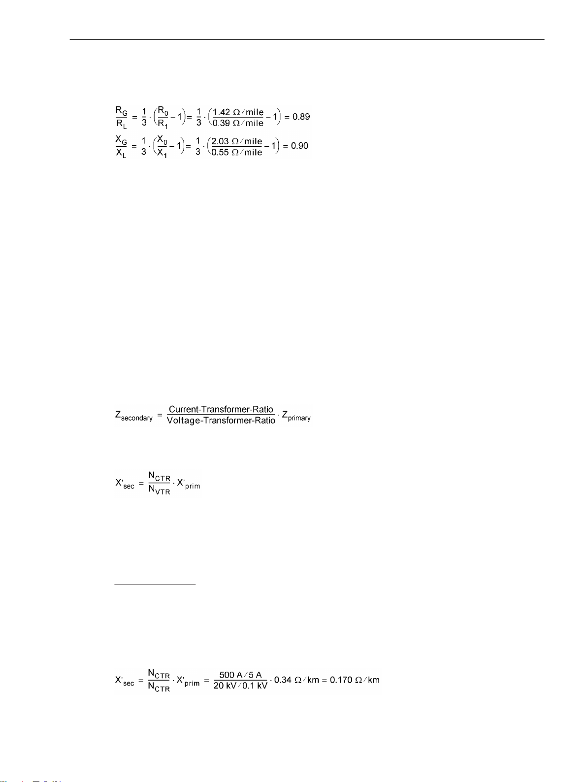
X1/s = 0.34 Ω/km (0.55 Ω/mile) Positive sequence reactance
For ground impedance ratios, the following results:
[formfehl-260602-kn, 1, en_US]
Reactance per Unit Length (only for Fault Location)
The setting of the reactance per unit length is only important for the utilization of the line fault location function. The reactance setting enables the protective relay to indicate the fault location in terms of distance.
The reactance value X' is entered as a reference value x', i.e. in Ω/mile if set to distance unit Miles (address
215, see Section 2.1.3.2 Setting Notes under "Distance Unit") or in Ω/km if set to distance unit km. If, after
having entered the reactance per unit length, the distance unit is changed under address 215, the reactance
per unit length must be reconfigured in accordance with the new distance unit.
The values under address 1106 (km) or 1105 (Miles) apply if only one line section is available and to all faults
that occur outside the defined line sections.
If several line sections are set, the following shall apply:
for line section 1, addresses 6004(km) or 6003 (Miles)
•
for line section 2, addresses 6014 (km) or 6013 (Miles),
•
for line section 3, addresses 6024 (km) or 6023 (Miles).
•
When setting the parameters in DIGSI, the values can also be entered as primary values. In that case the
following conversion to secondary values is not required.
For the conversion of primary values to secondary values the following applies in general:
Functions
2.1 General
[zsekundaer-260602-kn, 1, en_US]
Likewise, the following applies to the reactance per unit length of a line:
[xsekundaer-260602-kn, 1, en_US]
with
N
CTR
N
VTR
— Transformation ratio of the current transformer
— Transformation ratio of the voltage transformer
Calculation example:
In the following, the same line as illustrated in the example for ground impedance ratios (above) and addi-
tional data on the voltage transformers will be used:
Current Transformers
500 A/5 A
Voltage Transformers 20 kV/0.1 kV
The secondary reactance per unit length is calculated as follows:
[xsekund-beispiel-260602-kn, 1, en_US]
SIPROTEC 4, 7SJ80, Manual 51
E50417-G1140-C343-A8, Edition 12.2017
Page 52

Functions
2.1 General
Line Angle (only for Fault Location)
The setting of the line angle is only important for the utilization of the line fault location function. The line
angle can be derived from the line constants. The following applies:
[formel-allg-ltgdaten-1-oz-310702, 1, en_US]
with RL being the ohmic resistance and XL being the reactance of the line.
The value under address 1109 applies if only one line section is available and to all faults that occur outside
the defined line sections.
If several line sections are set, the following shall apply:
for line section 1, address 6005
•
for line section 2, address 6015
•
for line section 3, address 6025
•
This data can be used for the entire line or line section, or as distance-related values, since the quotients are
independent of the distance. It is also irrelevant whether the quotients were derived from primary or secondary values.
Calculation Example::
110 kV free line 150 mm2 with the following data:
R'1 = 0.19 Ω/km (0.31 Ω/mile)
X'1 = 0.42 Ω/km (0.69 Ω/mile)
The line angle is calculated as follows:
[formel-allg-ltgdaten-2-oz-310702, 1, en_US]
The respective address must be set to Line angle = 66°.
Line Length (only for Fault Location)
The setting of the line length is only important for the utilization of the line fault location function. The line
length is required so that the fault location can be given as a reference value (in %). Furthermore, when using
several line sections, the respective length of the individual sections is defined.
The values under address 1110 (km) or 1111 (Miles apply if only one line section is available and to all faults
that occur outside the defined line sections.
If several line sections are set, the following shall apply:
for line section 1, addresses 6006 (km) or 6007 (Miles)
•
for line section 2, addresses 6016 (km) or 6017 (Miles)
•
for line section 3, addresses 6026 (km) or 6027 (Miles)
•
The length set for the entire line must correspond to the sum of lengths configured for the line sections. A
deviation of 10% max. is admissible.
Operating Range of the Overload Protection
The current threshold entered in address 1107 I MOTOR START limits the operating range of the overload
protection to larger current values. The thermal replica is kept constant for as long as this threshold is
exceeded.
52 SIPROTEC 4, 7SJ80, Manual
E50417-G1140-C343-A8, Edition 12.2017
Page 53

Inverting Power Measured Values/Metered Values
The directional values (power, power factor, work and related min., max., mean and setpoint values), calculated in the operational measured values, are usually defined a positive in the direction of the protected
object. This requires that the connection polarity for the entire device was configured accordingly in the
P.System Data 1 (compare also "Polarity of the Current Transformers", address 201). But it is also possible
to make different settings for the "forward" direction" for the protection functions and the positive direction
for the power etc., e.g. to have the active power supply (from the line to the busbar) displayed positively. To
do so, set address 1108 P,Q sign to reversed. If the setting is not reversed (default), the positive
direction for the power etc. corresponds to the "forward" direction for the protection functions. Section
4 Technical Data provides a detailed list of the values in question.
Functions
2.1 General
2.1.6.3
Settings
The table indicates region-specific presettings. Column C (configuration) indicates the corresponding secondary nominal current of the current transformer.
Addr. Parameter C Setting Options Default Setting Comments
1101 FullScaleVolt. 0.10 .. 800.00 kV 20.00 kV Measurem:FullScale-
Voltage(Equipm.rating)
1102 FullScaleCurr. 10 .. 50000 A 400 A Measurem:FullScaleCur-
rent(Equipm.rating)
1103 RE/RL -0.33 .. 7.00 1.00 Zero seq. compensating
factor RE/RL
1104 XE/XL -0.33 .. 7.00 1.00 Zero seq. compensating
factor XE/XL
1105 x' 1A 0.0050 .. 15.0000 Ω/mi 0.2420 Ω/mi feeder reactance per mile:
5A 0.0010 .. 3.0000 Ω/mi 0.0484 Ω/mi
x'
1106 x' 1A 0.0050 .. 9.5000 Ω/km 0.1500 Ω/km feeder reactance per km: x'
5A 0.0010 .. 1.9000 Ω/km 0.0300 Ω/km
1107 I MOTOR START 1A 0.40 .. 10.00 A 2.50 A Motor Start Current (Block
5A 2.00 .. 50.00 A 12.50 A
1108 P,Q sign not reversed
reversed
not reversed P,Q operational measured
49, Start 48)
values sign
1109 Line angle 10 .. 89 ° 85 ° Line angle
1110 Line length 0.1 .. 1000.0 km 100.0 km Line length in kilometer
1111 Line length 0.1 .. 650.0 Miles 62.1 Miles Line length in miles
6001 S1: RE/RL -0.33 .. 7.00 1.00 S1: Zero seq. compen-
sating factor RE/RL
6002 S1: XE/XL -0.33 .. 7.00 1.00 S1: Zero seq. compen-
sating factor XE/XL
6003 S1: x' 1A 0.0050 .. 15.0000 Ω/mi 0.2420 Ω/mi S1: feeder reactance per
5A 0.0010 .. 3.0000 Ω/mi 0.0484 Ω/mi
mile: x'
6004 S1: x' 1A 0.0050 .. 9.5000 Ω/km 0.1500 Ω/km S1: feeder reactance per
5A 0.0010 .. 1.9000 Ω/km 0.0300 Ω/km
km: x'
6005 S1: Line angle 10 .. 89 ° 85 ° S1: Line angle
6006 S1: Line length 0.1 .. 650.0 Miles 62.1 Miles S1: Line length in miles
6007 S1: Line length 0.1 .. 1000.0 km 100.0 km S1: Line length in kilometer
6011 S2: RE/RL -0.33 .. 7.00 1.00 S2: Zero seq. compen-
sating factor RE/RL
6012 S2: XE/XL -0.33 .. 7.00 1.00 S2: Zero seq. compen-
sating factor XE/XL
6013 S2: x' 1A 0.0050 .. 15.0000 Ω/mi 0.2420 Ω/mi S2: feeder reactance per
5A 0.0010 .. 3.0000 Ω/mi 0.0484 Ω/mi
mile: x'
SIPROTEC 4, 7SJ80, Manual 53
E50417-G1140-C343-A8, Edition 12.2017
Page 54

Functions
2.1 General
Addr. Parameter C Setting Options Default Setting Comments
6014 S2: x' 1A 0.0050 .. 9.5000 Ω/km 0.1500 Ω/km S2: feeder reactance per
5A 0.0010 .. 1.9000 Ω/km 0.0300 Ω/km
km: x'
6015 S2: Line angle 10 .. 89 ° 85 ° S2: Line angle
6016 S2: Line length 0.1 .. 650.0 Miles 62.1 Miles S2: Line length in miles
6017 S2: Line length 0.1 .. 1000.0 km 100.0 km S2: Line length in kilometer
6021 S3: RE/RL -0.33 .. 7.00 1.00 S3: Zero seq. compen-
sating factor RE/RL
6022 S3: XE/XL -0.33 .. 7.00 1.00 S3: Zero seq. compen-
sating factor XE/XL
6023 S3: x' 1A 0.0050 .. 15.0000 Ω/mi 0.2420 Ω/mi S3: feeder reactance per
5A 0.0010 .. 3.0000 Ω/mi 0.0484 Ω/mi
mile: x'
6024 S3: x' 1A 0.0050 .. 9.5000 Ω/km 0.1500 Ω/km S3: feeder reactance per
5A 0.0010 .. 1.9000 Ω/km 0.0300 Ω/km
km: x'
6025 S3: Line angle 10 .. 89 ° 85 ° S3: Line angle
6026 S3: Line length 0.1 .. 650.0 Miles 62.1 Miles S3: Line length in miles
6027 S3: Line length 0.1 .. 1000.0 km 100.0 km S3: Line length in kilometer
2.1.6.4
No. Information Type of
Information List
Comments
Information
126 ProtON/OFF IntSP Protection ON/OFF (via system port)
356 >Manual Close SP >Manual close signal
466.4010 Cmd Trip IntSP Trip via control command
501 Relay PICKUP OUT Relay PICKUP
511 Relay TRIP OUT Relay GENERAL TRIP command
533 Ia = VI Primary fault current Ia
534 Ib = VI Primary fault current Ib
535 Ic = VI Primary fault current Ic
561 Man.Clos.Detect OUT Manual close signal detected
2720 >Enable ANSI#-2 SP >Enable 50/67-(N)-2 (override 79 blk)
4601 >52-a SP >52-a contact (OPEN, if bkr is open)
4602 >52-b SP >52-b contact (OPEN, if bkr is closed)
16019 >52 Wear start SP >52 Breaker Wear Start Criteria
16020 52 WearSet.fail OUT 52 Wear blocked by Time Setting Failure
16027 52WL.blk I PErr OUT 52 Breaker Wear Logic blk Ir-CB>=Isc-CB
16028 52WL.blk n PErr OUT 52 Breaker W.Log.blk SwCyc.Isc>=SwCyc.Ir
18420 >Trip via BI SP >Trip via Binary Input
18421 Trip via GOOSE ExSP Trip via GOOSE
18423 Direct Trip OUT Direct Trip
18424 PI Trip NC OUT PI Trip NC(ON,if Device ok & No Trip)
18425 >DDI Open SP >DDI Open status
54 SIPROTEC 4, 7SJ80, Manual
E50417-G1140-C343-A8, Edition 12.2017
Page 55

Functions
2.1 General
2.1.7
2.1.7.1
2.1.7.2
Interface Selection
IEC 61850 GOOSE Function
2.1.7.3
No.
009.0100 Failure Modul IntSP Failure EN100 Modul
009.0101 Fail Ch1 IntSP Failure EN100 Link Channel 1 (Ch1)
009.0102 Fail Ch2 IntSP Failure EN100 Link Channel 2 (Ch2)
EN100-Module
Functional Description
The Ethernet EN100-Modul enables integration of the 7SJ80 in 100-Mbit communication networks in control
and automation systems with the protocols according to IEC 61850 standard. This standard permits uniform
communication of the devices without gateways and protocol converters. Even when installed in heterogeneous environments, SIPROTEC 4 relays therefore provide for open and interoperable operation. Parallel to the
process control integration of the device, this interface can also be used for communication with DIGSI and for
inter-relay communication via GOOSE.
Setting Notes
No special settings are required for operating the Ethernet system interface module (IEC 1850, Ethernet
EN100-Modul). If the ordered version of the device is equipped with such a module, it is automatically allo-
cated to the interface available for it, namely Port B.
The GOOSE function can be disabled via a device parameter. For more information, please refer to Section
2.1.2.2 Setting Notes.
Information List
Information Type of
Information
Comments
SIPROTEC 4, 7SJ80, Manual 55
E50417-G1140-C343-A8, Edition 12.2017
Page 56

Functions
2.2 Overcurrent Protection 50, 51, 50N, 51N
2.2
2.2.1
Overcurrent Protection 50, 51, 50N, 51N
The overcurrent protection is provided with a total of four elements each for the phase currents and the
ground current. All elements are independent from each other and can be combined as desired.
If it is desired in isolated or resonant-grounded systems that three-phase devices should work together with
two-phase protection equipment, the overcurrent protection can be configured in such a way that it allows
twophase operation besides the three-phase mode (see Section 2.1.3.2 Setting Notes).
The high-set elements 50-2, 50-3, 50N-2, 50N-3 as well as the overcurrent elements 50-1 and 50N-1 always
operate with a definite tripping time (51), the elements 51 and 51N always with an inverse tripping time (50).
Applications
The non-directional overcurrent protection is applicable for networks that are radial and supplied from a
•
single source or open looped networks, for backup protection of differential protective schemes of all
types of lines, transformers, generators and busbars.
General
The overcurrent protection for the ground current can either operate with measured values ΙN or with the
quantities 3Ι0 calculated from the three phase currents. Which values are used depends on the setting of
parameter 613 Gnd O/Cprot. w. and the selected type of connection of the current transformers. Information on this can be found in Chapter 2.1.3.2 Setting Notes, connection examples in Appendix C Connection
Examples. Devices featuring a sensitive ground current input, however, generally use the calculated quantity
3Ι0.
All overcurrent elements enabled in the device may be blocked via the automatic reclosing function
(depending on the cycle) or via an external signal to the binary inputs of the device. Removal of blocking
during pickup will restart time delays. The Manual Close signal is an exception in this case. If a circuit breaker
is manually closed onto a fault, it can be re-opened immediately. For overcurrent elements or high-set
elements the delay may be bypassed via a Manual Close pulse, thus resulting in high speed tripping. This pulse
is extended up to at least 300 ms.
The automatic reclosure function 79 may also initiate immediate tripping for the overcurrent and high-set
elements depending on the cycle.
Pickup of the definite-time elements can be stabilized by setting the dropout times. This protection is used in
systems where intermittent faults occur. Combined with electromechanical relays, it allows different dropout
responses to be adjusted and a time grading of digital and electromechanical relays to be implemented.
Pickup and delay settings may be quickly adapted to system requirements via dynamic setting changeover
(see Section 2.4 Dynamic Cold Load Pickup).
Tripping by the 50-1 and 51 elements (in phases), 50N-1 and 51N elements (in ground path) may be blocked
for inrush conditions by utilizing the inrush restraint feature.
The following table gives an overview of the interconnections to other functions of the devices 7SJ80.
Table 2-2
Overcurrent
Protection
Elements
50-1 • • • •
50-2 • • •
50-3 • • •
51 • • • •
50N-1 • • • •
50N-2 • • •
50N-3 • • •
56 SIPROTEC 4, 7SJ80, Manual
Interconnection to other functions
Connection to
Automatic
Reclosing
Manual
CLOSE
Dynamic Cold Load
Pickup
E50417-G1140-C343-A8, Edition 12.2017
Inrush Restraint
Page 57

Functions
2.2 Overcurrent Protection 50, 51, 50N, 51N
2.2.2
Overcurrent
Protection
Elements
Connection to
Automatic
Reclosing
Manual
CLOSE
Dynamic Cold Load
Pickup
Inrush Restraint
51N • • • •
Definite Time, High-set Elements 50-3, 50-2, 50N-3, 50N-2
For each element, an individual pickup value 50-3 PICKUP, 50-2 PICKUP or 50N-3 PICKUP, 50N-2
PICKUP is set. For 50-3 PICKUP and 50N-3 PICKUP, it is possible to measure the Instantaneous in
addition to Fundamental and True RMS. If set to Instantaneous, the element picks up at 2 · √2 · setting
value (rms). Each phase and ground current is compared separately per element with the common pickup
values 50-3 PICKUP, 50-2 PICKUP or 50N-3 PICKUP, 50N-2 PICKUP. If the respective pickup value is
exceeded, this is signaled. After the user-defined time delays 50-3 DELAY, 50-2 DELAY or 50N-3 DELAY,
50N-2 DELAY have elapsed, trip commands are issued which are available for each element. The dropout
value is roughly equal to 95% of the pickup value for currents > 0.3 Ι
neous values has been parameterized for the 50-3 or 50N-3 element, the dropout ratio is set to 90 %.
Pickup can be stabilized by setting dropout times 1215 50 T DROP-OUT or 1315 50N T DROP-OUT. This
time is started and maintains the pickup condition if the current falls below the threshold. Therefore, the function does not drop out at high speed. The trip delay time 50-3 DELAY, 50-2 DELAY or 50N-3 DELAY,
50N-2 DELAY continues running in the meantime. After the dropout delay time has elapsed, the pickup is
reported OFF and the trip delay time is reset unless the threshold 50-3 PICKUP, 50-2 PICKUP or 50N-3
PICKUP, 50N-2 PICKUP has been exceeded again. If the threshold is exceeded again during the dropout
delay time, the time is canceled. The trip delay time 50-3 DELAY, 50-2 DELAY or 50N-3 DELAY, 50N-2
DELAY continues running in the meantime. If the threshold value is exceeded after this time has elapsed, the
trip command is issued immediately. If the threshold value is not exceeded at this time, there is no reaction. If
the threshold value is exceeded again after expiry of the trip command delay time while the dropout delay
time is still running, tripping is initiated immediately.
These elements can be blocked by the automatic reclosing function (79 AR).
The pickup values of each 50-2, 50-3 Element for phase currents and 50N-2, 50N-3 Element for the ground
current and the element-specific time delays can be set individually.
The following figures give an example of logic diagrams for the high-set elements 50-2 PICKUP or 50N-2
PICKUP. They also apply analogously to the high-set elements 50-3 PICKUP and 50N-3 PICKUP.
. If the measurement of the instanta-
Nom
SIPROTEC 4, 7SJ80, Manual 57
E50417-G1140-C343-A8, Edition 12.2017
Page 58

Functions
2.2 Overcurrent Protection 50, 51, 50N, 51N
[7sj6x-hochstromst-i-fuer-ph-20061212, 1, en_US]
Figure 2-4
Logic diagram for 50-2 high-set element for phases
If parameter MANUAL CLOSE is set to 50-2 instant. or 50-3 instant. and manual close detection is
used, a pickup causes instantaneous tripping, even if the element is blocked via binary input.
The same applies to 79 AR 50-2 inst. or 79 AR 50-3 inst.
58 SIPROTEC 4, 7SJ80, Manual
E50417-G1140-C343-A8, Edition 12.2017
Page 59

Functions
2.2 Overcurrent Protection 50, 51, 50N, 51N
2.2.3
[7sj6x-hochstromst-ie-20061212, 1, en_US]
Figure 2-5
Logic diagram for 50N-2 high-set element
If parameter MANUAL CLOSE is set to 50N-2 instant. or 50N-3 instant. and manual close detection is
used, a pickup causes instantaneous tripping, even if the element is blocked via binary input. The same applies
to AR 50N-2 inst.
The same applies to 79 AR 50N-2 inst. or 79 AR 50N-3 inst.
Definite Time Overcurrent Elements 50-1, 50N-1
For each element an individual pickup value 50-1 PICKUP or 50N-1 PICKUP is set. Apart from Fundamental, the True RMS can also be measured. Each phase and ground current is compared separately with
the setting value 50-1 or 50N-1 for each element. If the respective value is exceeded, this is signaled. If the
inrush restraint feature (see below) is applied, either the normal pickup signals or the corresponding inrush
signals are output as long as inrush current is detected. After user-configured time delays 50-1 DELAY or
50N-1 DELAY have elapsed, a trip signal is issued if no inrush current is detected or inrush restraint is disabled. If the inrush restraint feature is enabled and an inrush condition exists, no tripping takes place but a
message is recorded and displayed indicating when the overcurrent element time delay elapses. Trip signals
and signals on the expiration of time delay are available separately for each element. The dropout value is
approximately 95% of the pickup value for currents > 0.3 INom.
Pickup can be stabilized by setting dropout times 1215 50 T DROP-OUT or1315 50N T DROP-OUT. This
time is started and maintains the pickup condition if the current falls below the threshold. Therefore, the function does not drop out at high speed. The trip-command delay time 50-1 DELAY or 50N-1 DELAY continues
running in the meantime. After the dropout delay time has elapsed, the pickup is reported OFF and the trip
delay time is reset unless the threshold 50-1 or 50N-1 has been exceeded again. If the threshold is exceeded
again during the dropout delay time, the time is canceled. However, the trip-command delay time 50-1
SIPROTEC 4, 7SJ80, Manual 59
E50417-G1140-C343-A8, Edition 12.2017
Page 60

Functions
2.2 Overcurrent Protection 50, 51, 50N, 51N
DELAY or 50N-1 DELAY continues running. If the threshold value is exceeded after its expiry, the trip
command is issued immediately. If the threshold value is not exceeded at this time, there is no reaction. If the
threshold value is exceeded again after expiry of the trip-command delay time, while the dropout delay time is
still running, tripping occurs immediately.
Pickup stabilization of the overcurrent elements 50-1 or 50N-1 by means of settable dropout time is deactivated if an inrush pickup is present since an inrush does not represent an intermittent fault.
These elements can be blocked by the automatic reclosing function (79 AR).
The pickup values of each 50-1 element for phase currents and 50N-1 element for the ground current and the
element-specific time delays can be set individually.
The following figures show the logic diagrams for the current elements 50-1 and 50N-1.
[7sj6x-ueberstromst-i-fuer-ph-20061212, 1, en_US]
Figure 2-6
Logic diagram for the 50-1 overcurrent element for phases
If parameter MANUAL CLOSE is set to 50 -1 instant. and manual close detection is used, a pickup causes
instantaneous tripping, even if blocking of the element via binary input is present.
The same applies to 79 AR 50-1 inst.
The dropout delay only operates if no inrush was detected. An incoming inrush will reset a running dropout
delay time.
60 SIPROTEC 4, 7SJ80, Manual
E50417-G1140-C343-A8, Edition 12.2017
Page 61

[7sj6x_rueckfallverzoegerung_i_gr_ph_260803_he, 1, en_US]
Figure 2-7 Logic diagram of the dropout delay for 50-1
Functions
2.2 Overcurrent Protection 50, 51, 50N, 51N
[7sj6x-ueberstromst-ie-20061212, 1, en_US]
Figure 2-8
Logic diagram for the 50N-1 overcurrent current element
If parameter MANUAL CLOSE is set to 50N-1 instant. and manual close detection applies, the trip is initiated as soon as the pickup conditions arrive, even if the element is blocked via a binary input.
The same applies to 79 AR 50N-1 inst.
The pickup values of each 50-1, 50-2 element for the phase currents and 50N-1, 50N-2 element for the
ground current and the valid delay times for each element can be set individually.
The dropout delay only functions if no inrush was detected. An incoming inrush will reset a running dropout
time delay.
SIPROTEC 4, 7SJ80, Manual 61
E50417-G1140-C343-A8, Edition 12.2017
Page 62

Functions
2.2 Overcurrent Protection 50, 51, 50N, 51N
[7sj6x_rueckfallverzoegerung_i_gr_erde_260803_he, 1, en_US]
Figure 2-9 Logic of the dropout delay for 50N-1
2.2.4
Inverse Time Overcurrent Elements 51, 51N
Inverse time overcurrent elements are dependent on the ordering version. They always operate with an
inverse time Curve in accordance with IEC or ANSI standards. The characteristics and associated formulas are
given in the Technical Data.
When configuring one of the inverse-time characteristics, the definite-time elements 50-3, 50-2,and 50-1 are
also active (see Section "Definite-time High-set Current Elements 50-3, 50-2, 50N-3, 50N-2 " and "Definitetime Overcurrent Elements 50-1, 50N-1 ").
A voltage restraint can optionally be set (see Section “Inverse Time Overcurrent Protection (Voltagecontrolled / Voltage-restraint”).
Pickup Behavior
For each element, an individual pickup value 51 PICKUP or 51N PICKUP is set. Apart from Fundamental,
the True RMS can also be measured. Each phase and ground current is separately compared with the setting
value 51 or 51N per element. If a current exceeds 1.1 times the setting value, the corresponding element picks
up and is signaled individually. If the inrush restraint function is used, either the normal pickup signals or the
corresponding inrush signals are issued as long as inrush current is detected. If the 51 element picks up, the
tripping time is calculated from the actual fault current flowing, using an integrating method of measurement.
The calculated tripping time depends on the selected tripping curve. Once this time has elapsed, a trip signal is
issued provided that no inrush current is detected or inrush restraint is disabled. If the inrush restraint function
is enabled and an inrush condition exists, no tripping takes place but a message is issued indicating when the
overcurrent element time delay elapses.
These elements can be blocked by the automatic reclosing feature (79 AR).
For ground current element 51N, the characteristic may be selected independently of the characteristic used
for phase currents.
Pickup values of elements 51 (phase currents) and 51N (ground current) and the relevant time multiplicators
may be set individually.
The following two figures show the logic diagrams for the inverse time overcurrent protection.
62 SIPROTEC 4, 7SJ80, Manual
E50417-G1140-C343-A8, Edition 12.2017
Page 63

Functions
2.2 Overcurrent Protection 50, 51, 50N, 51N
[7sj6x-abhueberstromzeit-phase-20061212, 1, en_US]
Figure 2-10
Logic diagram of the inverse-time overcurrent protection element for phases
If an ANSI characteristic is configured, parameter 1209 51 TIME DIAL is used instead of parameter 1208 51
TIME DIAL.
If parameter MANUAL CLOSE is set to 51 instant. and manual close detection applies, the trip is initiated
as soon as the pickup conditions arrive, even if the element is blocked via a binary input.
The same applies to 79 AR 51N inst.
SIPROTEC 4, 7SJ80, Manual 63
E50417-G1140-C343-A8, Edition 12.2017
Page 64

Functions
2.2 Overcurrent Protection 50, 51, 50N, 51N
[7sj6x-abhueberstromzeit-erde-20061212, 1, en_US]
Figure 2-11
If an ANSI characteristic is configured, parameter 1309 51N TIME DIAL is used instead of parameter 1308
51N TIME DIAL.
If parameter MANUAL CLOSE is set to 51N instant. and manual close detection applies, the trip is initiated
as soon as the pickup conditions arrive, even if the element is blocked via binary input.
The same applies to 79 AR 51N inst.
Dropout Behavior
For the ANSI or IEC characteristics, you can select whether an element drops out instantaneously after a
threshold has been undershot or whether dropout is performed by means of disk emulation. "Instantaneous"
means that the picked-up element drops out when 95 % of the pickup value is undershot. For a new pickup,
the time delay starts at zero.
The disk emulation evokes a dropout process (timer counter is decrementing) which begins after de-energization. This process corresponds to the reset of a Ferraris disk (explaining its denomination "disk emulation"). In
case several faults occur in succession, the "history" is taken into consideration due to the inertia of the
Ferraris disk and the time response is adapted. Reset begins as soon as 90 % of the setting value is undershot,
in accordance to the dropout curve of the selected characteristic. In the range between the dropout value
(95 % of the pickup value) and 90 % of the setting value, the incrementing and the decrementing processes
are in idle state.
Disk emulation offers advantages when the overcurrent relay elements must be coordinated with conventional electromechanical overcurrent relays located towards the source.
Logic diagram of the inverse-time overcurrent protection element for ground
64 SIPROTEC 4, 7SJ80, Manual
E50417-G1140-C343-A8, Edition 12.2017
Page 65

Functions
2.2 Overcurrent Protection 50, 51, 50N, 51N
2.2.5
Inverse Time Overcurrent Protection 51V (Voltage-controlled / Voltagerestraint)
Undervoltage Consideration
The inverse time overcurrent protection is provided with an undervoltage detection that can be disabled
(address 1223 VOLT. INFLUENCE). This function can influence overcurrent detection by means of two
different methods:
Voltage-controlled: If a set voltage threshold is undershot, the overcurrent element is released.
•
Voltage-restraint: The pickup threshold of the overcurrent element depends on the voltage magnitude.
•
A lower voltage decreases the current pickup value (see Figure 2-13). In the range between V/V
to 0.25 a linear, directly proportional dependence is realized, and therefore the following applies:
Nom
= 1.00
[spannungsabhaengigkeit-des-anregewertes, 1, en_US]
Figure 2-12 Voltage influence of the pickup value
The 51 PICKUP value is decreased proportional to the voltage decrease. Consequently, for constant current Ι
the Ι/ 51 PICKUP ratio is increased and the tripping time is reduced. Compared with the standard curves represented in Section “Technical Data” the tripping curve shifts to the left side as the voltage decreases.
Switching to the lower pickup value or decreasing the pickup threshold is carried out phase-selectively. The
assignment of voltages to current-carrying phases is shown in the following table.
Table 2-3
Controlling voltages in relation to the fault currents
Strom Spannung
Ι
A
Ι
B
Ι
C
VA – V
VB – V
VC – V
B
C
A
In order to avoid an unwanted operation in case of a voltage transformer fault, a function blocking is implemented via a binary input controlled by the voltage transformer protection breaker as well as via the deviceinternal measuring voltage failure detection ("Fuse Failure Monitor").
The following two figures show the logic diagrams for the inverse time overcurrent protection with undervoltage consideration.
SIPROTEC 4, 7SJ80, Manual 65
E50417-G1140-C343-A8, Edition 12.2017
Page 66

Functions
2.2 Overcurrent Protection 50, 51, 50N, 51N
[7sjx_logic_51-phase-schleife-aktiv, 1, en_US]
Figure 2-13
Logic diagram of the voltage-controlled inverse time overcurrent protection
66 SIPROTEC 4, 7SJ80, Manual
E50417-G1140-C343-A8, Edition 12.2017
Page 67
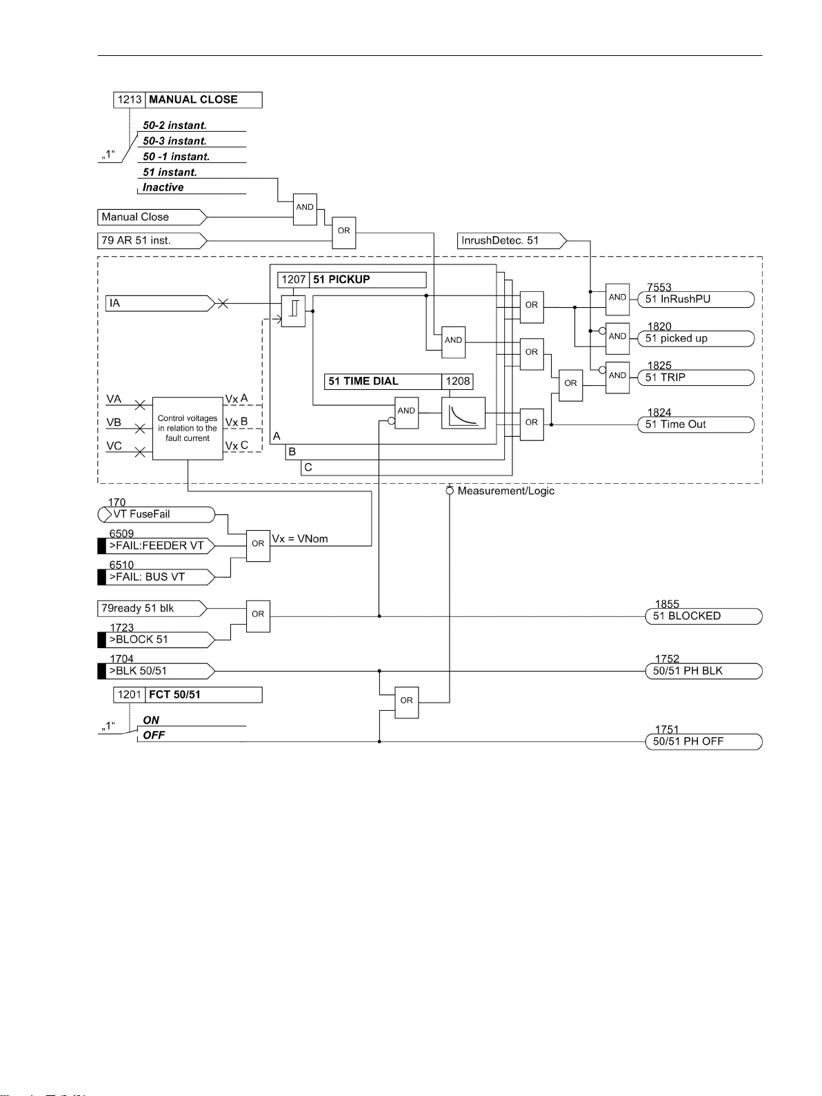
Functions
2.2 Overcurrent Protection 50, 51, 50N, 51N
[7sjx_logic_51-phase, 1, en_US]
Logic diagram of the voltage-restraint inverse-time overcurrent protection
2.2.6
Figure 2-14
Dynamic Cold Load Pickup Function
It may be necessary to dynamically increase the pickup thresholds of the overcurrent protection if certain
system components exhibit an increased power consumption when they are switched on after a long period
of zero voltage (e.g. air-conditioning systems, heating installations, motors). Thus, a general increase of
pickup thresholds can be avoided taking into consideration such starting conditions.
This dynamic pickup value changeover fuction is common to all overcurrent elements and is described in
Section 2.4 Dynamic Cold Load Pickup. The alternative pickup values can be set individually for each element
of the time overcurrent protection.
SIPROTEC 4, 7SJ80, Manual 67
E50417-G1140-C343-A8, Edition 12.2017
Page 68

Functions
2.2 Overcurrent Protection 50, 51, 50N, 51N
2.2.7
Inrush Restraint
When the multi-functional protective relay with local control 7SJ80 is installed, for instance, to protect a
power transformer, large magnetizing inrush currents will flow when the transformer is energized. These
inrush currents may be several times the nominal transformer current, and, depending on the transformer size
and design, may last from several tens of milliseconds to several seconds.
Although pickup of the relay elements is based only on the fundamental harmonic component of the measured currents, false device pickup due to inrush is still a potential problem since, depending on the transformer size and design, the inrush current also comprises a large component of the fundamental.
The 7SJ80 features an integrated inrush restraint function. It prevents the “normal” pickup of 50-1 or 51 relay
elements (not 50-2 and 50-3) in the phases and the ground path of all directional and non-directional overcurrent relay elements. The same is true for the alternative pickup thresholds of the dynamic cold load pickup
function. After detection of inrush currents above a pickup value, special inrush signals are generated. These
signals also initiate fault annunciations and start the associated trip delay time. If inrush conditions are still
present after the tripping time delay has elapsed, a corresponding message (
but the overcurrent tripping is blocked (see also logic diagrams of time overcurrent elements, Figure 2-6 to
Figure 2-11).
Inrush current contains a relatively large second harmonic component (twice the nominal frequency) which is
nearly absent during a fault current. The inrush restraint is based on the evaluation of the 2nd harmonic
present in the inrush current. For frequency analysis, digital filters are used to conduct a Fourier analysis of all
three phase currents and the ground current.
Inrush current is recognized if the following conditions are fulfilled at the same time:
The harmonic content is larger than the setting value 2202 2nd HARMONIC (minimum 0.125 * Ι
•
the currents do not exceed an upper limit value 2205 I Max;
•
an exceeding of a threshold value via an inrush restraint of the blocked element takes place.
•
In this case an inrush in the affected phase is recognized (annunciations 1840 to 1842 and 7558
Gnd Det
Since quantitative analysis of the harmonic components cannot be completed until a full line period has been
measured, pickup will generally be blocked by then. Therefore, assuming the inrush restraint feature is
enabled, a pickup message will be delayed by a full line period if no closing process is present. On the other
hand, trip delay times of the time overcurrent protection feature are started immediately even with the inrush
restraint being enabled. Time delays continue running with inrush currents present. If inrush blocking drops
out after the time delay has elapsed, tripping will occur immediately. Therefore, utilization of the inrush
restraint feature will not result in any additional tripping delays. If a relay element drops out during inrush
blocking, the associated time delay will reset.
„InRush Gnd Det“, see Figure 2-15) and its blocking being carried out.
„....Timeout.“
) is output,
Nom,sec
InRush
);
Cross Blocking
Since inrush restraint operates individually for each phase, protection is ideal where a power transformer is
energized into a single-phase fault and inrush currents are detected on a different healthy phase. However,
the protection feature can be configured to allow that not only this phase element but also the remaining
elements (including ground) are blocked (the so-called CROSS BLOCK function, address 2203) if the permissible harmonic component of the current is exceeded for only one phase.
Please take into consideration that inrush currents flowing in the ground path will
the phase elements.
Cross blocking is reset if there is no more inrush in any phase. Furthermore, the cross blocking function may
also be limited to a particular time interval (address 2204 CROSS BLK TIMER). After expiry of this time
interval, the cross blocking function will be disabled, even if inrush current is still present.
The inrush restraint has an upper limit: Above this (via adjustable parameter 2205 I Max) current blocking is
suppressed since a high-current fault is assumed in this case.
The following figure shows the inrush restraint influence on the time overcurrent elements including crossblocking.
68 SIPROTEC 4, 7SJ80, Manual
E50417-G1140-C343-A8, Edition 12.2017
not cross-block tripping by
Page 69

Functions
2.2 Overcurrent Protection 50, 51, 50N, 51N
[7sj6x_einschaltstabilisierung-150502-kn, 1, en_US]
2.2.8
Figure 2-15
Pickup Logic and Tripping Logic
Logic diagram for inrush restraint
The pickup annunciations of the individual phases (or ground) and the individual element are combined with
each other in such a way that the phase information and the element that has picked up are issued.
SIPROTEC 4, 7SJ80, Manual 69
E50417-G1140-C343-A8, Edition 12.2017
Page 70

Functions
2.2 Overcurrent Protection 50, 51, 50N, 51N
Table 2-4 Pickup Indications of Overcurrent Protection
Internal indication Figure Output indication FNo.
50-3 A PU
50-2 A PU
50-1 A PU
51 A PU
50-3 B PU
50-2 B PU
50-1 B PU
51 B PU
50-3 C PU
50-2 C PU
50-1 C PU
51 C PU
50N-3 PU
50N-2 PU
50N-1 PU
51N PU
50-3 A PU
50-3 B PU
50-3 C PU
50N-3 PU
50-2 A PU
50-2 B PU
50-2 C PU
50N-2 PU Figure 2-5
50-1 A PU
50-1 B PU
50-1 C PU
50N-1 PU Figure 2-5
51 A PU
51 B PU
51 C PU
51N PU Figure 2-11
(All pickups)
Figure 2-4
Figure 2-6
Figure 2-10
Figure 2-4
Figure 2-6
Figure 2-10
Figure 2-4
Figure 2-6
Figure 2-10
Figure 2-5
Figure 2-8
Figure 2-11
Figure 2-4
Figure 2-4
Figure 2-4
Figure 2-6
Figure 2-6
Figure 2-6
Figure 2-10
Figure 2-10
Figure 2-10
50/51 Ph A PU
50/51 Ph B PU
50/51 Ph C PU
50N/51NPickedup
50-3 picked up
50N-3 picked up
50-2 picked up
50N-2 picked up
50-1 picked up
50N-1 picked up
51 picked up
51N picked up
50(N)/51(N) PU
1762
1763
1764
1765
1767
1768
1800
1831
1810
1834
1820
1837
1761
In the trip signals, the element which initiated the tripping is also indicated.
2.2.9
70 SIPROTEC 4, 7SJ80, Manual
Two-phase Overcurrent Protection (Only Non-Directional)
The 2-phase overcurrent protection functionality is used in isolated or grounded systems where interaction
with existing 2-phase protection equipment is required. As an isolated or grounded system remains operational with a 1-phase ground fault, this protection serves to detect double ground faults with high ground
fault currents. The respective feeder must be switched off only in this case. A 2-phase measurement is sufficient for this purpose. In order to ensure selectivity of the protection in this section of the system, only phases
A and C are monitored.
If 250 50/51 2-ph prot (settable in P.System Data 1) is set to ON, ΙB is not used for threshold comparison. If the fault is a simple ground fault in B, the element will not pick up. A double ground fault is assumed
only after pickup on A or C, causing the element to pick up and trip after the delay time has elapsed.
E50417-G1140-C343-A8, Edition 12.2017
Page 71
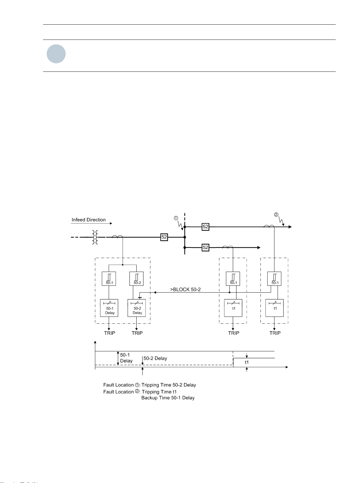
i
i
Functions
2.2 Overcurrent Protection 50, 51, 50N, 51N
NOTE
With inrush detection activated and inrush only on B, no cross blocking will take place in the other phases.
On the other hand, if inrush with cross blocking is activated on A or C, B will also be blocked.
2.2.10
Application Example
Fast Busbar Protection Using Reverse Interlocking
Each of the current elements can be blocked via binary inputs. A setting parameter determines whether the
binary input operates in the normally open (i.e. actuated when energized) or the normally closed (i.e. actuated when de-energized) mode. This allows fast busbar protection to be applied in star systems or open ring
systems by applying "reverse interlocking". This principle is often used, for example, in distribution systems,
auxiliary systems of power plants and similar systems, where a station supply transformer supplied from the
transmission grid serves internal loads of the generation station via a medium voltage bus with multiple
feeders (Figure 2-16).
The reverse interlocking principle is based on the following: Time overcurrent protection of the busbar feeder
trips with a short time delay T 50-2 independent of the grading times of the feeders, unless the pickup of the
next load-side overcurrent protection element blocks the busbar protection (Figure 2-16). Always the protection element nearest to the fault will trip with the short time delay since this element cannot be blocked by a
protection element located behind the fault. Time elements T 50-1 or T51 are still effective as backup
element. Pickup signals output by the load-side protective relay are used as input message
a binary input at the feeder-side protective relay.
>BLOCK 50-2
via
[rueckwverr-150502-kn, 1, en_US]
Figure 2-16
SIPROTEC 4, 7SJ80, Manual 71
E50417-G1140-C343-A8, Edition 12.2017
Reverse interlocking protection scheme
Page 72

Functions
2.2 Overcurrent Protection 50, 51, 50N, 51N
2.2.11
General
Measurement Methods
Setting Notes
When selecting the time overcurrent protection in DIGSI, a dialog box appears with several tabs for setting the
individual parameters. Depending on the functional scope specified during configuration of the protection
functions under addresses 112 Charac. Phase and 113 Charac. Ground, the number of tabs can vary. If
address FCT 50/51 was set to Definite Time, or Charac. Ground was set to Definite Time, then
only the settings for the definite time elements are available. The selection of TOC IEC or TOC ANSI makes
available additional inverse time characteristics. The superimposed high-set elements 50-2, 50-3 or 50N-2,
50N-3 are available in all these cases.
Parameter 250 50/51 2-ph prot can also be set to activate two-phase overcurrent protection.
Under address 1201 FCT 50/51, overcurrent protection for phases and under address 1301 FCT 50N/51N,
the ground overcurrent protection can be switched ON or OFF.
Pickup values, time delays, and characteristics for ground protection are set separately from the pickup values,
time delays and characteristic curves associated with phase protection. Because of this, relay coordination for
ground faults is independent of relay coordination for phase faults, and more sensitive settings can often be
applied to directional ground protection.
Depending on the setting of parameter 251 CT Connect., the device can also be used in specific system
configuration with regard to current connections. Further information can be found under Section
2.1.3.2 Setting Notes, “Current Connections”.
The comparison values to be used for the respective element can be set in the setting sheets for the elements.
Measurement of the fundamental harmonic (standard method):
•
This measurement method processes the sampled values of the current and filters in numerical order the
fundamental harmonic so that the higher harmonics or transient peak currents remain largely unconsidered.
Measurement of the true RMS value
•
The current amplitude is derived from the sampled values in accordance with the definition equation of
the true RMS value. This measurement method should be selected when higher harmonics are to be
considered by the function (e.g. in capacitor banks).
Measurement with instantaneous values
•
This procedure compares the instantaneous values to the set threshold. The element picks up at 2 · √2 ·
setting value (rms). It does not perform a mean-value calculation and is thus sensitive with regard to
disturbances. This measurement method should only be selected if an especially short pickup time of the
element is required. In this measurement procedure, the operating time of the element is reduced
compared to the measurement of effective values or fundamental harmonics (see “Technical Data”).
The type of the comparison values can be set under the following addresses:
50-3 element
50-2element Address 1220 50-2 measurem.
50-1 element Address 1221 50-1 measurem.
51 element Address 1222 51 measurem.
50N-3 element Address 1319 50N-3 measurem.
50N-2 element Address 1320 50N-2 measurem.
50N-1 element Address 1321 50N-1 measurem.
51Nelement Address 1322 51N measurem.
High-set Current Elements 50-2, 50-3 (phases)
The pickup current of the high-set element 50-2 PICKUP or50-3 PICKUP can be set at address 1202 or
1217. The corresponding delay time 50-2 DELAY or 50-3 DELAY can be configured under address 1203 or
Address 1219 50-3 measurem.
72 SIPROTEC 4, 7SJ80, Manual
E50417-G1140-C343-A8, Edition 12.2017
Page 73

Functions
2.2 Overcurrent Protection 50, 51, 50N, 51N
1218. It is usually used for purposes of current grading intended for large impedances that are prevalent in
transformers or generators. It is specified in such manner that it picks up faults up to this impedance.
Example of the high-set current element 50-2 PICKUP: Transformer used for busbar supply with the
following data:
Rated apparent power S
NomT
= 16 MVA
Transformer impedance ZT = 10 %
Primary nominal voltage V
Secondary nominal voltage V
Nom1
Nom2
= 110 kV
= 20 kV
Vector groups Dy 5
Neutral point Grounded
Fault power on 110 kV-side 1 GVA
Based on the data above, the following fault currents are calculated:
Three-Phase High Voltage Side Fault Current at 110 kV = 5250 A
Three-Phase Low Voltage Side Fault Current at 20 kV = 3928 A
On the High Voltage Side Flowing at 110 kV = 714 A
The nominal current of the transformer is:
Ι
= 84 A (High Voltage Side) Ι
NomT, 110
= 462 A (Low Voltage
NomT, 20
Side)
Current Transformer (High Voltage Side) 100 A/1 A
Current Transformer (Low Voltage Side) 500 A/1 A
Due to the following definition
[hochstrom-260602-kn, 1, en_US]
the following setting applies to the protection device: The 50-2 high-set current element must be set higher
than the maximum fault current which is detected during a low side fault on the high side. To reduce fault
probability as much as possible even when fault power varies, the following setting is selected in primary
values: 50-2 /Ι
= 10, i.e. 50-2 = 1000 A. The same applies analogously when using the high-set element
Nom
50-3.
Increased inrush currents, if their fundamental component exceeds the setting value, are rendered harmless
by delay times (address 1203 50-2 DELAY or 1218 50-3 DELAY).
The principle of the "reverse interlocking" utilizes the multi-element function of the time overcurrent protec-
tion: Element 50-2 PICKUP is applied as a fast busbar protection with a shorter safety delay time 50-2
DELAY (e.g. 100 ms). For faults at the outgoing feeders, element 50-2 is blocked. The elements 50-1 or 51
serve as backup protection. The pickup values of both elements (50-1 PICKUP or 51 PICKUP and 50-2 PICKUP)
are set equal. The delay time 50-1 DELAY or 51 TIME DIAL is set in such manner that it overgrades the
delay for the outgoing feeders.
The selected time is an additional delay time and does not include the operating time (measuring time,
dropout time). The delay can also be set to ∞. In this case, the element will not trip after pickup. However,
pickup, will be signaled. If the 50-2 element or the 50-3 element is not required at all, the pickup threshold
50-2 or 50-3 is set to ∞. This setting prevents tripping and the generation of a pickup message.
High-set Current Elements 50N-2, 50N-3 (ground)
The pickup current of the high-set element 50N-2 PICKUP or 50N-3 PICKUP can be set at address 1302 or
1317. The corresponding delay time 50N-2 DELAY or 50N-3 DELAY can be configured under address 1303
or 1318. The same considerations apply to these settings as they did for phase currents discussed earlier.
The selected time is an additional delay time and does not include the operating time (measuring time,
dropout time). The delay can also be set to ∞. In this case, the element will not trip after pickup. However,
SIPROTEC 4, 7SJ80, Manual 73
E50417-G1140-C343-A8, Edition 12.2017
Page 74

Functions
2.2 Overcurrent Protection 50, 51, 50N, 51N
pickup, will be signaled. If the 50N-2 element or 50N-3 element is not required at all, the pickup threshold
50N-2 or 50N-3 should be set to ∞. This setting prevents tripping and the generation of a pickup message.
50-1 Element (phases)
For setting the 50-1 element, it is the maximum anticipated load current that must be considered above all.
Pickup due to overload should never occur since in this mode the device operates as fault protection with
correspondingly short tripping times and not as overload protection. For this reason, a setting equal to 20% of
the expected peak load is recommended for line protection, and a setting equal to 40% is recommended for
transformers and motors.
The settable time delay (address 1205 50-1 DELAY) results from the grading coordination chart defined for
the system.
The selected time is an additional delay time and does not include the operating time (measuring time,
dropout time). The delay can also be set to ∞. In this case, the element will not trip after pickup. However,
pickup, will be signaled. If the 50-1 element is not required at all, then the pickup threshold 50-1 should be set
to ∞. This setting prevents tripping and the generation of a pickup message.
50N-1 Element (ground)
The 50N-1 element is normally set based on minimum ground fault current.
If the relay is used to protect transformers or motors with large inrush currents, the inrush restraint feature of
7SJ80 may be used for the 50N–1 relay element. It can be enabled or disabled for both the phase current and
the ground current in address 2201 INRUSH REST.. The characteristic values of the inrush restraint are listed
in Subsection "Inrush Restraint".
The settable delay time (address 1305 50N-1 DELAY) results from the time coordination chart defined for the
system. For ground currents in a grounded system a separate coordination timer with short time delays can be
applied.
The selected time is an additional delay time and does not include the operating time (measuring time,
dropout time). The delay can also be set to ∞. In this case, the element will not trip after pickup. However,
pickup, will be signaled. If the 50N-1 element is not required at all, the pickup threshold 50N-1 PICKUP should
be set to ∞. This setting prevents tripping and the generation of a pickup message.
Pickup Stabilization (Definite Time)
The configurable dropout times 1215 50 T DROP-OUT or 1315 50N T DROP-OUT can be set to implement a
uniform dropout behavior when using electromechanical relays. This is necessary for a time grading. The
dropout time of the electromechanical relay must be known to this end. Subtract the dropout time of the
device (see Technical Data) from this value and enter the result in the parameters.
51 Element (phases) with IEC or ANSI characteristics
Having set address 112 Charac. Phase = TOC IEC or TOC ANSI when configuring the protection functions (Section 2.1.1.2 Setting Notes), the parameters for the inverse time characteristics will also be available.
If address 112 Charac. Phase was set to TOC IEC, you can select the desired IEC characteristic (Normal
Inverse, Very Inverse, Extremely Inv. or Long Inverse) at address 1211 51 IEC CURVE. If
address 112 Charac. Phase was set to TOC ANSI, you can select the desired ANSI characteristic (Very
Inverse, Inverse, Short Inverse, Long Inverse, Moderately Inv., Extremely Inv. or Definite Inv.) at address 1212 51 ANSI CURVE.
If the inverse time trip characteristic is selected, it must be noted that a safety factor of about 1.1 has already
been included between the pickup value and the setting value. This means that a pickup will only occur if a
current of about 1.1 times the setting value is present. If Disk Emulation was selected at address 1210 51
Drop-out, reset will occur in accordance with the reset curve as described before.
The current value is set in address 1207 51 PICKUP. The setting is mainly determined by the maximum
anticipated operating current. Pickup due to overload should never occur since in this mode, the device operates as fault protection with correspondingly short tripping times and not as overload protection.
The corresponding time multiplier for an IEC characteristic is set at address 1208 51 TIME DIAL and in
address 1209 51 TIME DIAL for an ANSI characteristic. It must be coordinated with the time coordination
chart of the system.
74 SIPROTEC 4, 7SJ80, Manual
E50417-G1140-C343-A8, Edition 12.2017
Page 75

The time multiplier can also be set to ∞. In this case, the element will not trip after pickup. However, pickup
will be signaled. If the 51 element is not required at all, address 112 Charac. Phase should be set to Defi-
nite Time during protection function configuration (see Section 2.1.1.2 Setting Notes).
If highly sensitive settings close to the load current are required in weak power systems or transformers, the
element can be stabilized via the undervoltage as an additional criterion for the power system fault. The operating modes can be set in address 1223 VOLT. INFLUENCE. In a voltage-controlled operation, the voltage
threshold is defined via parameter 1224 51V V< below which the current element is released
51N Element (ground) with IEC or ANSI Characteristics
Having set address 113 Charac. Ground = TOC IEC when configuring the protection functions (Section
2.1.1 Functional Scope), the parameters for the inverse time characteristics will also be available. Specify in
address 113 Charac. Ground = TOC IEC the desired IEC characteristic (Normal Inverse, Very
Inverse, Extremely Inv. or Long Inverse). If address 113 Charac. Ground = TOC ANSI, you can
select the desired ANSI characteristic (Very Inverse, Inverse, Short Inverse, Long Inverse,
Moderately Inv., Extremely Inv. or Definite Inv.) in address 1312 51N ANSI CURVE.
If the inverse time trip characteristic is selected, it must be noted that a safety factor of about 1.1 has already
been included between the pickup value and the setting value. This means that a pickup will only occur if a
current of about 1.1 times the setting value is present. If Disk Emulation was selected at address 1310 51
Drop-out, reset will occur in accordance with the reset curve as described before.
The current value is set in address 1307 51N PICKUP. The setting is mainly determined by the minimum
anticipated ground fault current.
The corresponding time multiplier for an IEC characteristic is set at address 1308 51N TIME DIAL and at
address 1309 51N TIME DIAL for an ANSI characteristic. This has to be coordinated with the grading coordination chart of the network. For ground currents with grounded network, you can often set up a separate
grading coordination chart with shorter delay times.
The time multiplier can also be set to ∞. In this case, the element will not trip after pickup. However, pickup
will be signaled. If the 51N-TOC elementt is not required at all, address 113 Charac. Ground should be set
to Definite Time during configuration of the protection functions (see Section 2.1.1 Functional Scope).
Functions
2.2 Overcurrent Protection 50, 51, 50N, 51N
Inrush Restraint
When applying the protection device to transformers where high inrush currents are to be expected, the
7SJ80 can make use of an inrush restraint function for the overcurrent elements 50-1, 51, 50N-1 and 51N.
Inrush restraint is only effective and accessible if address 122 InrushRestraint was set to Enabled. If this
function is not required, then Disabled is set. In address 2201 INRUSH REST., the function is switched ON
or OFF jointly for the overcurrent elements 50-1 PICKUP,51 PICKUP, 50N-1 PICKUP and 51N PICKUP
The inrush restraint is based on the evaluation of the 2nd harmonic present in the inrush current. Upon
delivery from the factory, a ratio Ι2f/Ιf of 15 % is set. Under normal circumstances, this setting will not need to
be changed. The setting value is identical for all phases and ground. However, the component required for
restraint may be adjusted to system conditions in address 2202 2nd HARMONIC. To provide more restraint in
exceptional cases, where energizing conditions are particularly unfavorable, a smaller value can be set in the
aforementioned address, e.g. 12 %. Irrespective of parameter 2202 2nd HARMONIC, rush blocking will only
occur if the absolute value of the 2nd harmonic is at least 0.125 * INom,sec.
The effective duration of the cross-blocking 2203 CROSS BLK TIMER can be set to a value between 0 s
(harmonic restraint active for each phase individually) and a maximum of 180 s (harmonic restraint of a phase
blocks also the other phases for the specified duration).
If the current exceeds the value set in address 2205 I Max, no further restraint will take place for the 2nd
harmonic.
Manual Close Mode (phases ground)
When a circuit breaker is closed onto a faulted line, a high-speed trip by the circuit breaker is usually desired.
For overcurrent or high-set element the delay may be bypassed via a Manual Close pulse, thus resulting in
instantaneous tripping. The internal "Manual close" signal is built from the binary input signal >Manual Close
356
(no.
). The internal "Manual close" signal remains active as long as the binary input signal >Manual Close is
active, but at least for 300 ms (see the following logic diagram). To enable the device to react properly on
SIPROTEC 4, 7SJ80, Manual 75
E50417-G1140-C343-A8, Edition 12.2017
Page 76

i
i
Functions
2.2 Overcurrent Protection 50, 51, 50N, 51N
occurrence of a fault in the phase element, address 1213 MANUAL CLOSE has to be set accordingly. Correspondingly, address 1313 MANUAL CLOSE is considered for the ground path address. Thus, the user determines for both elements, the phase and the ground element, what pickup value is active with what delay
when the circuit breaker is closed manually.
[lo_7sj6-hand-ein, 1, en_US]
Figure 2-17 Manual close feature
External Control Command
If the manual close signal is not sent from 7SJ80 device, i.e. neither via the built-in operator interface nor via a
serial interface, but directly from a control acknowledgment switch, this signal must be passed to a 7SJ80
binary input, and configured accordingly (
CLOSE can become effective. The alternative Inactive means that all elements operate as per configuration
even with manual close and do not get special treatment.
Internal Control Function
If the manual close signal is sent via the internal control function of the device, an internal connection of
information has to be established via CFC (interlocking task level) using the CMD_Information block (see
Figure 2-18).
>Manual Close
), so that the element selected for MANUAL
[handein-260602-kn, 1, en_US]
Figure 2-18 Example for the generation of a manual close signal using the internal control function
NOTE
For an interaction between the automatic reclosing function (79 AR) and the control function, an extended
CFC logic is necessary. See margin heading “Close command: Directly or via Control” in the Setting Notes of
the automatic reclosing function (Section 2.15.6 Setting Notes).
Interaction with the Automatic Reclosing Function (phases)
If reclosing follows, high-speed and simultaneous protection against faults with 50-2 or 50-3 is usually
desired. If the fault still exists after the first reclosing, the 50-1 or the 51 element will be initiated with graded
tripping times, that is, element 50-2 or 50-3 will be blocked. You can use the parameters 1214 50-2 active
or 1216 50-3 active active for this purpose to define whether or not the 50-2 or the 50-3 element is
impacted by a release signal of the internal or an external automatic reclosing system. The setting with 79
active means that the 50-2 or the 50-3 element will only be released if automatic reclosing is not blocked. If
this is not desired, the setting Always is selected so that the 50-2 or the 50-3 element is always active.
The integrated automatic reclosing function of 7SJ80 also provides the option to individually determine for
each overcurrent element whether tripping or blocking is to be carried out instantaneously or unaffected by
the AR with the set time delay (see Section 2.15 Automatic Reclosing System 79).
Interaction with the Automatic Reclosing Function (ground)
When reclosing occurs, it is desirable to have high-speed protection against faults with 50N-2 or 50N-3. If the
fault still exists after the first reclosing, the 50N-1 or the 51N element will be initiated with coordinated tripping times, that is, element 50N-2 or 50N-3 will be blocked. At address 1314 50N-2 active or 1316 50N-3
active active it can be specified whether the 50N-2 or the 50N-3 element should be influenced by the
76 SIPROTEC 4, 7SJ80, Manual
E50417-G1140-C343-A8, Edition 12.2017
Page 77

Functions
2.2 Overcurrent Protection 50, 51, 50N, 51N
release signal of an internal or external automatic reclosing system. Address with 79 active determines
that the 50N-2 or the 50N-3 element will only operate if automatic reclosing is not blocked. If not desired,
select the setting Always so that the 50N-2 or the 50N-3 element will always operate, as configured.
The integrated automatic reclosing function of 7SJ62/64 also provides the option to individually determine for
each overcurrent element whether tripping or blocking is to be carried out instantaneously or unaffected by
the AR with the set time delay (see Section 2.15 Automatic Reclosing System 79).
2.2.12
Addr. Parameter C Setting Options Default Setting Comments
1201 FCT 50/51 ON
1202 50-2 PICKUP 1A 0.10 .. 35.00 A; ∞ 4.00 A 50-2 Pickup
1203 50-2 DELAY 0.00 .. 60.00 sec; ∞ 0.00 sec 50-2 Time Delay
1204 50-1 PICKUP 1A 0.10 .. 35.00 A; ∞ 1.00 A 50-1 Pickup
1205 50-1 DELAY 0.00 .. 60.00 sec; ∞ 0.50 sec 50-1 Time Delay
1207 51 PICKUP 1A 0.10 .. 4.00 A 1.00 A 51 Pickup
1208 51 TIME DIAL 0.05 .. 3.20 sec; ∞ 0.50 sec 51 Time Dial
1209 51 TIME DIAL 0.50 .. 15.00 ; ∞ 5.00 51 Time Dial
1210 51 Drop-out Instantaneous
1211 51 IEC CURVE Normal Inverse
1212 51 ANSI CURVE Very Inverse
1213A MANUAL CLOSE 50-3 instant.
1214A 50-2 active Always
1215A 50 T DROP-OUT 0.00 .. 60.00 sec 0.00 sec 50 Drop-Out Time Delay
1216A 50-3 active Always
Settings
Addresses which have an appended “A” can only be changed with DIGSI, under “Additional Settings”.
The table indicates region-specific default settings. Column C (configuration) indicates the corresponding
secondary nominal current of the current transformer.
ON 50, 51 Phase Time Overcur-
OFF
5A 0.50 .. 175.00 A; ∞ 20.00 A
5A 0.50 .. 175.00 A; ∞ 5.00 A
5A 0.50 .. 20.00 A 5.00 A
Disk Emulation Drop-out characteristic
Disk Emulation
Normal Inverse IEC Curve
Very Inverse
Extremely Inv.
Long Inverse
Very Inverse ANSI Curve
Inverse
Short Inverse
Long Inverse
Moderately Inv.
Extremely Inv.
Definite Inv.
50-2 instant. Manual Close Mode
50-2 instant.
50 -1 instant.
51 instant.
Inactive
Always 50-2 active
with 79 active
Always 50-3 active
with 79 active
rent
SIPROTEC 4, 7SJ80, Manual 77
E50417-G1140-C343-A8, Edition 12.2017
Page 78

Functions
2.2 Overcurrent Protection 50, 51, 50N, 51N
Addr. Parameter C Setting Options Default Setting Comments
1217 50-3 PICKUP 1A 1.00 .. 35.00 A; ∞ ∞ A 50-3 Pickup
5A 5.00 .. 175.00 A; ∞ ∞ A
1218 50-3 DELAY 0.00 .. 60.00 sec; ∞ 0.00 sec 50-3 Time Delay
1219A 50-3 measurem. Fundamental
Fundamental 50-3 measurement of
True RMS
Instantaneous
1220A 50-2 measurem. Fundamental
Fundamental 50-2 measurement of
True RMS
1221A 50-1 measurem. Fundamental
Fundamental 50-1 measurement of
True RMS
1222A 51 measurem. Fundamental
Fundamental 51 measurement of
True RMS
1223 VOLT. INFLUENCE NO
NO 51V Voltage Influence
Volt. controll.
Volt. restraint
1224 51V V< 10.0 .. 125.0 V 75.0 V 51V V< Threshold for
Release Ip
1301 FCT 50N/51N ON
OFF
ON 50N, 51N Ground Time
Overcurrent
1302 50N-2 PICKUP 1A 0.05 .. 35.00 A; ∞ 0.50 A 50N-2 Pickup
5A 0.25 .. 175.00 A; ∞ 2.50 A
1303 50N-2 DELAY 0.00 .. 60.00 sec; ∞ 0.10 sec 50N-2 Time Delay
1304 50N-1 PICKUP 1A 0.05 .. 35.00 A; ∞ 0.20 A 50N-1 Pickup
5A 0.25 .. 175.00 A; ∞ 1.00 A
1305 50N-1 DELAY 0.00 .. 60.00 sec; ∞ 0.50 sec 50N-1 Time Delay
1307 51N PICKUP 1A 0.05 .. 4.00 A 0.20 A 51N Pickup
5A 0.25 .. 20.00 A 1.00 A
1308 51N TIME DIAL 0.05 .. 3.20 sec; ∞ 0.20 sec 51N Time Dial
1309 51N TIME DIAL 0.50 .. 15.00 ; ∞ 5.00 51N Time Dial
1310 51N Drop-out Instantaneous
Disk Emulation Drop-Out Characteristic
Disk Emulation
1311 51N IEC CURVE Normal Inverse
Normal Inverse IEC Curve
Very Inverse
Extremely Inv.
Long Inverse
1312 51N ANSI CURVE Very Inverse
Very Inverse ANSI Curve
Inverse
Short Inverse
Long Inverse
Moderately Inv.
Extremely Inv.
Definite Inv.
1313A MANUAL CLOSE 50N-3 instant.
50N-2 instant. Manual Close Mode
50N-2 instant.
50N-1 instant.
51N instant.
Inactive
78 SIPROTEC 4, 7SJ80, Manual
E50417-G1140-C343-A8, Edition 12.2017
Page 79

Functions
2.2 Overcurrent Protection 50, 51, 50N, 51N
Addr. Parameter C Setting Options Default Setting Comments
1314A 50N-2 active Always
With 79 Active
1315A 50N T DROP-OUT 0.00 .. 60.00 sec 0.00 sec 50N Drop-Out Time Delay
1316A 50N-3 active Always
with 79 active
1317 50N-3 PICKUP 1A 0.25 .. 35.00 A; ∞ ∞ A 50N-3 Pickup
1318 50N-3 DELAY 0.00 .. 60.00 sec; ∞ 0.05 sec 50N-3 Time Delay
1319A 50N-3 measurem. Fundamental
True RMS
Instantaneous
1320A 50N-2 measurem. Fundamental
True RMS
1321A 50N-1 measurem. Fundamental
True RMS
1322A 51N measurem. Fundamental
True RMS
2201 INRUSH REST. OFF
ON
2202 2nd HARMONIC 10 .. 45 % 15 % 2nd. harmonic in % of
2203 CROSS BLOCK NO
YES
2204 CROSS BLK TIMER 0.00 .. 180.00 sec 0.00 sec Cross Block Time
2205 I Max 1A 0.30 .. 25.00 A 7.50 A Maximum Current for
5A 1.50 .. 125.00 A 37.50 A
Always 50N-2 active
Always 50N-3 active
Fundamental 50N-3 measurement of
Fundamental 50N-2 measurement of
Fundamental 50N-1 measurement of
Fundamental 51N measurement of
OFF Inrush Restraint
fundamental
NO Cross Block
Inrush Restraint
2.2.13
No.
1704 >BLK 50/51 SP >BLOCK 50/51
1714 >BLK 50N/51N SP >BLOCK 50N/51N
1718 >BLOCK 50-3 SP >BLOCK 50-3
1719 >BLOCK 50N-3 SP >BLOCK 50N-3
1721 >BLOCK 50-2 SP >BLOCK 50-2
1722 >BLOCK 50-1 SP >BLOCK 50-1
1723 >BLOCK 51 SP >BLOCK 51
1724 >BLOCK 50N-2 SP >BLOCK 50N-2
1725 >BLOCK 50N-1 SP >BLOCK 50N-1
1726 >BLOCK 51N SP >BLOCK 51N
1751 50/51 PH OFF OUT 50/51 O/C switched OFF
1752 50/51 PH BLK OUT 50/51 O/C is BLOCKED
1753 50/51 PH ACT OUT 50/51 O/C is ACTIVE
1756 50N/51N OFF OUT 50N/51N is OFF
1757 50N/51N BLK OUT 50N/51N is BLOCKED
1758 50N/51N ACT OUT 50N/51N is ACTIVE
Information List
Information Type of
Information
Comments
SIPROTEC 4, 7SJ80, Manual 79
E50417-G1140-C343-A8, Edition 12.2017
Page 80

Functions
2.2 Overcurrent Protection 50, 51, 50N, 51N
No. Information Type of
Comments
Information
1761 50(N)/51(N) PU OUT 50(N)/51(N) O/C PICKUP
1762 50/51 Ph A PU OUT 50/51 Phase A picked up
1763 50/51 Ph B PU OUT 50/51 Phase B picked up
1764 50/51 Ph C PU OUT 50/51 Phase C picked up
1765 50N/51NPickedup OUT 50N/51N picked up
1767 50-3 picked up OUT 50-3 picked up
1768 50N-3 picked up OUT 50N-3 picked up
1769 50-3 TRIP OUT 50-3 TRIP
1770 50N-3 TRIP OUT 50N-3 TRIP
1787 50-3 TimeOut OUT 50-3 TimeOut
1788 50N-3 TimeOut OUT 50N-3 TimeOut
1791 50(N)/51(N)TRIP OUT 50(N)/51(N) TRIP
1800 50-2 picked up OUT 50-2 picked up
1804 50-2 TimeOut OUT 50-2 Time Out
1805 50-2 TRIP OUT 50-2 TRIP
1810 50-1 picked up OUT 50-1 picked up
1814 50-1 TimeOut OUT 50-1 Time Out
1815 50-1 TRIP OUT 50-1 TRIP
1820 51 picked up OUT 51 picked up
1824 51 Time Out OUT 51 Time Out
1825 51 TRIP OUT 51 TRIP
1831 50N-2 picked up OUT 50N-2 picked up
1832 50N-2 TimeOut OUT 50N-2 Time Out
1833 50N-2 TRIP OUT 50N-2 TRIP
1834 50N-1 picked up OUT 50N-1 picked up
1835 50N-1 TimeOut OUT 50N-1 Time Out
1836 50N-1 TRIP OUT 50N-1 TRIP
1837 51N picked up OUT 51N picked up
1838 51N TimeOut OUT 51N Time Out
1839 51N TRIP OUT 51N TRIP
1840 PhA InrushDet OUT Phase A inrush detection
1841 PhB InrushDet OUT Phase B inrush detection
1842 PhC InrushDet OUT Phase C inrush detection
1843 INRUSH X-BLK OUT Cross blk: PhX blocked PhY
1851 50-1 BLOCKED OUT 50-1 BLOCKED
1852 50-2 BLOCKED OUT 50-2 BLOCKED
1853 50N-1 BLOCKED OUT 50N-1 BLOCKED
1854 50N-2 BLOCKED OUT 50N-2 BLOCKED
1855 51 BLOCKED OUT 51 BLOCKED
1856 51N BLOCKED OUT 51N BLOCKED
1866 51 Disk Pickup OUT 51 Disk emulation Pickup
1867 51N Disk Pickup OUT 51N Disk emulation picked up
7551 50-1 InRushPU OUT 50-1 InRush picked up
7552 50N-1 InRushPU OUT 50N-1 InRush picked up
7553 51 InRushPU OUT 51 InRush picked up
80 SIPROTEC 4, 7SJ80, Manual
E50417-G1140-C343-A8, Edition 12.2017
Page 81

Functions
2.2 Overcurrent Protection 50, 51, 50N, 51N
No. Information Type of
Comments
Information
7554 51N InRushPU OUT 51N InRush picked up
7556 InRush OFF OUT InRush OFF
7557 InRush BLK OUT InRush BLOCKED
7558 InRush Gnd Det OUT InRush Ground detected
7559 67-1 InRushPU OUT 67-1 InRush picked up
7560 67N-1 InRushPU OUT 67N-1 InRush picked up
7561 67-TOC InRushPU OUT 67-TOC InRush picked up
7562 67N-TOCInRushPU OUT 67N-TOC InRush picked up
7563 >BLOCK InRush SP >BLOCK InRush
7564 Gnd InRush PU OUT Ground InRush picked up
7565 Ia InRush PU OUT Phase A InRush picked up
7566 Ib InRush PU OUT Phase B InRush picked up
7567 Ic InRush PU OUT Phase C InRush picked up
10034 50-3 BLOCKED OUT 50-3 BLOCKED
10035 50N-3 BLOCKED OUT 50N-3 BLOCKED
SIPROTEC 4, 7SJ80, Manual 81
E50417-G1140-C343-A8, Edition 12.2017
Page 82

Functions
2.3 Directional Overcurrent Protection 67, 67N
2.3
2.3.1
Directional Overcurrent Protection 67, 67N
The directional time overcurrent protection comprises three elements each for phase currents and the ground
current that can operate directional or non-directional. All elements are independent of each other and can be
combined as desired.
High current element 67-2 and overcurrent element 67-1 always operate with a definite tripping time, the
third element 67-TOC always operates with inverse tripping time.
Applications
The directional overcurrent protection allows the application of multifunctional protection devices 7SJ80
•
also in systems where protection coordination depends on knowing both the magnitude of the fault
current and the direction of power flow to the fault location.
The non-directional overcurrent protection described in Section 2.2 Overcurrent Protection 50, 51, 50N,
•
51N may operate as overlapping backup protection or may be disabled. Additionally, individual elements
(e.g. 67-2 and/or 67N-2) may be interconnected with the directional overcurrent protection.
For parallel lines or transformers supplied from a single source, only directional overcurrent protection
•
allows selective fault detection.
For line sections supplied from two sources or in ring-operated lines, the overcurrent protection has to be
•
supplemented by the element-specific directional criterion.
General
For parallel lines or transformers supplied from a single source (see Figure 2-19), the second feeder (II) is
opened on occurrence of a fault in the first feeder (I) if tripping of the breaker in the parallel feeder is not
prevented by a directional measuring element (at B). Therefore, where indicated with an arrow (Figure 2-19),
directional overcurrent protection is applied. Please ensure that the "forward" direction of the protection
element is in the direction of the line (or object to be protected). This is not necessarily identical with the
direction of the normal load flow, as shown in Figure 2-19.
[ueberstromzeitschutz-bei-paralleltransformatoren-020626-kn, 1, en_US]
Figure 2-19 Overcurrent protection for parallel transformers
82 SIPROTEC 4, 7SJ80, Manual
E50417-G1140-C343-A8, Edition 12.2017
Page 83

Functions
2.3 Directional Overcurrent Protection 67, 67N
For line sections supplied from two sources or in ring-operated lines, the overcurrent protection has to be
supplemented by the directional criterion. Figure 2-20 shows a ring system where both energy sources are
merged to one single source.
[zweiseitig-gespeister-leitungszug-260602-kn, 1, en_US]
Figure 2-20 Transmission lines with sources at both ends
Depending on the setting of parameter 613 50N/51N/67N w., the ground current element can operate
either with measured values IN or with the values 3I0 calculated from the three phase currents. Devices
featuring a sensitive ground current input, however, use the calculated quantity 3I0.
The directional orientation Forward, Reverse or Non-Directional can be set individually for each
element (Non-Directional from V4.7 on).
For each element the time can be blocked via binary input or automatic reclosing (cycle-dependent), thus
suppressing the trip command. Removal of blocking during pickup will restart time delays. The Manual Close
signal is an exception. If a circuit breaker is manually closed onto a fault, it can be re-opened immediately. For
overcurrent elements or high-set elements the delay may be bypassed via a Manual Close pulse, thus resulting
in high-speed tripping.
Furthermore, immediate tripping may be initiated in conjunction with the automatic reclosing function (cycle
dependant).
Pickup stabilization for the 67/67N elements of the directional overcurrent protection can be accomplished by
means of settable dropout times. This protection comes into use in systems where intermittent faults occur.
Combined with electromechanical relays, it allows different dropout responses to be adjusted and a time
grading of digital and electromechanical relays to be implemented.
Pickup and delay settings may be quickly adjusted to system requirements via dynamic setting switching (see
Section 2.4 Dynamic Cold Load Pickup).
Utilizing the inrush restraint feature tripping may be blocked by the 67-1, 67-TOC, 67N-1, and 67N-TOC
elements in phases and ground path when inrush current is detected.
The following table gives an overview of these interconnections to other functions of the 7SJ80 devices.
Table 2-5
Directional Time
Overcurrent Protec-
Interconnection to other functions
Connection to Automatic Reclosing
Manual CLOSE Dynamic Cold
Load Pickup
Inrush Restraint
tion Elements
67-1 • • • •
67-2 • • •
67-3 • • •
67-TOC • • • •
67N-1 • • • •
67N-2 • • •
SIPROTEC 4, 7SJ80, Manual 83
E50417-G1140-C343-A8, Edition 12.2017
Page 84

Functions
2.3 Directional Overcurrent Protection 67, 67N
2.3.2
Directional Time
Overcurrent Protec-
Connection to Automatic Reclosing
Manual CLOSE Dynamic Cold
Load Pickup
Inrush Restraint
tion Elements
67N-3 • • •
67N-TOC • • • •
Definite Time Directional High-set Elements 67-2, 67N-2, 67-3, 67N-3
For each element an individual pickup value 67-2 PICKUP, 67-3 PICKUP or 67N-2 PICKUP, 67N-3
PICKUP is set which can be measured as Fundamental or True RMS. Each phase current and the ground
current is compared with the common pickup value for each element 67-2 PICKUP, 67-3 PICKUP or
67N-2 PICKUP, 67N-3 PICKUP, and it is signaled when the value is exceeded provided that the fault direc-
tion is the same as the parameterized direction. After the associated delay times 67-2 DELAY, 67-3 DELAY
or 67N-2 DELAY, 67N-3 DELAY have expired, the tripping commands are initiated which are equally available separately for each element. The dropout value is approximately 95% of the pickup value for currents >
0.3 Ι
Pickup can be stabilized by setting dropout times 1518 67 T DROP-OUT or 1618 67N T DROP-OUT. This
time is started and maintains the pickup condition if the current falls below the threshold. Therefore, the function does not drop out instantaneously. The trip delay times 50-2 DELAY, 67-3 DELAY or 50N-2 DELAY,
67N-3 DELAY continue during that time. After the dropout delay time has elapsed, the pickup is reported
OFF and the trip delay time is reset unless the threshold 50-2 PICKUP, 67-3 PICKUP or 50N-2 PICKUP,
67N-3 PICKUP has been exceeded again. If the threshold is exceeded again during the dropout delay time,
the time is canceled. The trip delay time 50-2 DELAY, 67-3 DELAY or 50N-2 DELAY, 67N-3 DELAY
continues. If the threshold value is exceeded after this time has elapsed, the trip command is issued immediately. If the threshold value is not exceeded at this time, there is no reaction. If the threshold value is
exceeded again after expiry of the trip command delay time, while the dropout delay time is still running, tripping is initiated immediately.
Each of these elements can be directional or non-directional (non-directional from V4.7 on).
These elements can be blocked by the automatic reclosing function (79 AR).
The following figure gives an example of the logic diagram for the high-set elements 67-2 of the phase
currents. The high-set element 67-3 is structured identically.
Nom
.
84 SIPROTEC 4, 7SJ80, Manual
E50417-G1140-C343-A8, Edition 12.2017
Page 85

Functions
2.3 Directional Overcurrent Protection 67, 67N
[7sj6x_gerueberstromzeit_hochstromst-030903-he, 1, en_US]
Figure 2-21
Logic diagram for directional high-set element 67-2 for phases
If parameter MANUAL CLOSE is set to 67-2 instant. or 67-3 instant. and manual close detection is
present, a pickup causes instantaneous tripping even if the element is blocked via binary input.
The same applies to 79 AR 67-2 or 79 AR 67-3 instantaneous.
2.3.3
Definite Time, Directional Time Overcurrent Elements 67-1, 67N-1
For each element, an individual pickup value 67-1 PICKUP or 67N-1 PICKUP is set which can be measured
as Fundamental or True RMS. Phase and ground currents are compared separately with the common
setting value 67-1 PICKUP or 67N-1 PICKUP. Currents above the setting values are recognized separately
when fault direction is equal to the configured direction. If the inrush restraint function is used, either the
normal pickup signals or the corresponding inrush signals are issued as long as inrush current is detected.
When the relevant delay times 67-1 DELAY, 67N-1 DELAY have expired, a tripping command is issued
SIPROTEC 4, 7SJ80, Manual 85
E50417-G1140-C343-A8, Edition 12.2017
Page 86

Functions
2.3 Directional Overcurrent Protection 67, 67N
unless an inrush has been recognized or inrush restraint is active. If the inrush restraint feature is enabled, and
an inrush condition exists, no tripping takes place, but a message is recorded and displayed indicating when
the overcurrent element time delay elapses. Trip signals and other flags for each element are issued when the
element times out. The dropout value is roughly equal to 95% of the pickup value for currents > 0.3 Ι
Pickup can be stabilized by setting dropout times 1518 67 T DROP-OUT or 1618 67N T DROP-OUT. This
time is started and maintains the pickup condition if the current falls below the threshold. Therefore, the function does not drop out at high speed. The trip-command delay time 50-1 DELAY or 50N-1 DELAY continues
in the meantime. After the dropout delay time has elapsed, the pickup is reported OFF and the trip delay time
is reset unless the threshold 50-1 PICKUP or 50N-1 PICKUP has been exceeded again. If the threshold is
exceeded again during the dropout delay time, the time is canceled. The trip-command delay time 50-1
DELAY or 50N-1 DELAY continues in the meantime. Should the threshold value be exceeded after its expiry,
the trip command is issued immediately. If the threshold value is not exceeded at this time, there will be no
reaction. If the threshold value is exceeded again after expiry of the trip-command delay time, while the
dropout delay time is still running, tripping occurs immediately.
The inrush restraint of the overcurrent elements 50-1 PICKUP or 50N-1 PICKUP is disabled via configurable dropout times if an inrush pickup occurs, because the occurrence of an inrush does not constitute an
intermittent fault.
Each of these elements can be directional or non-directional (non-directional from V4.7 on).
These elements can be blocked by the automatic reclosure function (AR).
The following figure shows by way of an example the logic diagram for the directional overcurrent element
67-1.
Nom
.
86 SIPROTEC 4, 7SJ80, Manual
E50417-G1140-C343-A8, Edition 12.2017
Page 87
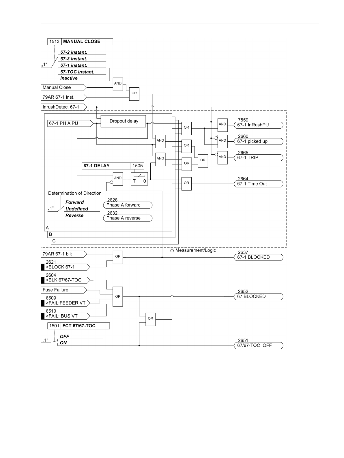
Functions
2.3 Directional Overcurrent Protection 67, 67N
[7sj6x_gerueberstromzeit_ueberstromst-030903-he, 1, en_US]
Figure 2-22
Logic diagram for the directional relay element 67-1 for phases
If parameter MANUAL CLOSE is set to 67-1 instant. and manual close detection is present, a pickup
causes instantaneous tripping even if the element is blocked via binary input.
The same applies to 79 AR 67-1 instantaneous.
The dropout delay does only function if no inrush was detected. An approaching inrush resets an already
running dropout time delay.
SIPROTEC 4, 7SJ80, Manual 87
E50417-G1140-C343-A8, Edition 12.2017
Page 88

Functions
2.3 Directional Overcurrent Protection 67, 67N
[7sj6x_gerrueckfallverzoegerung_i_gr_ph, 1, en_US]
Figure 2-23 Logic of the dropout delay for 67-1
2.3.4
Inverse Time, Directional Overcurrent Elements 67-TOC, 67N-TOC
Inverse time elements are dependent on the variant ordered. They operate either according to the IEC- or the
ANSI-standard. The characteristics and associated formulas are identical with those of the non-directional
overcurrent protection and are given in the Technical Data. When the inverse time curves are configured, the
definite time elements (67-2, 67-1) are also available.
Pickup Behavior
For each element, an individual pickup value 67-TOC PICKUP or 67N-TOC PICKUP is set which can be
measured as Fundamental or True RMS. Each phase and ground current is separately compared with the
common pickup value 67-TOC PICKUP or 67N-TOC PICKUP of each element. When a current value
exceeds the corresponding setting value by a factor of 1.1, the corresponding phase picks up and a message is
generated phase-selectively assuming that the fault direction is equal to the direction configured. If the inrush
restraint feature is used, either the normal pickup signals or the corresponding inrush signals are issued as
long as inrush current is detected. If the 67-TOC element picks up, the tripping time is calculated from the
actual fault current flowing, using an integrating method of measurement. The calculated tripping time
depends on the selected tripping curve. Once this time has elapsed, a trip signal is issued provided that no
inrush current is detected or inrush restraint is disabled. If the inrush restraint feature is enabled and an inrush
condition exists, no tripping takes place, but a message is recorded and displayed indicating when the overcurrent element time delay elapses.
For ground current element 67N-TOC PICKUP, the characteristic may be selected independently of the characteristic used for phase currents.
Pickup values of the 67-TOC (phases) and 67N-TOC (ground current) and the associated time multipliers may
be set individually.
Each of these elements can be directional or non-directional (non-directional from V4.7 on).
Dropout Behavior
When using an ANSI or IEC curve, it can be selected whether the dropout of an element is to occur instantaneously or whether dropout is to be performed by means of the disk emulation mechanism. "Instantaneously"
means that pickup drops out when the pickup value of approx. 95 % of the set pickup value is undershot. For a
new pickup, the time counter starts at zero.
The disk emulation evokes a dropout process (time counter is decrementing) which begins after de-energization. This process corresponds to the reset of a Ferraris disk (explaining its denomination "disk emulation"). In
case several faults occur in succession the "history" is taken into consideration due to the inertia of the Ferraris
disk and the time response is adapted. Reset begins as soon as 90 % of the setting value is undershot, in
accordance to the dropout curve of the selected characteristic. In the range between the dropout value (95 %
of the pickup value) and 90 % of the setting value, the incrementing and the decrementing processes are in
idle state.
Disk emulation offers advantages when the overcurrent relay elements must be coordinated with conventional electromechanical overcurrent relays located towards the source.
The following figure shows by way of an example the logic diagram for the 67-TOC relay element of the directional inverse time overcurrent protection of the phase currents.
88 SIPROTEC 4, 7SJ80, Manual
E50417-G1140-C343-A8, Edition 12.2017
Page 89

Functions
2.3 Directional Overcurrent Protection 67, 67N
[7sj6x_gerueberstromzeit_abh_ueberstrom_ip-150502-kn, 1, en_US]
Logic diagram for the directional overcurrent protection: 67-TOC relay element
2.3.5
Figure 2-24
Interaction with Fuse Failure Monitor (FFM)
False or undesired tripping can be caused by a measuring voltage that can be caused by either short-circuit or
broken wire in the voltage transformer's secondary system or an operation of the voltage transformer fuse.
Failure of the measuring voltage in one or two phases can be detected, and the directional time overcurrent
elements (Dir Phase and Dir Ground) can be blocked, see logic diagrams.
Undervoltage protection, sensitive ground fault detection and synchronization are also blocked in this case.
For additional information on the operation of the fuse failure monitor, see Section 2.11.1 Measurement
Supervision.
SIPROTEC 4, 7SJ80, Manual 89
E50417-G1140-C343-A8, Edition 12.2017
Page 90

Functions
2.3 Directional Overcurrent Protection 67, 67N
2.3.6
2.3.7
2.3.8
Dynamic Cold Load Pickup Function
It may be necessary to dynamically increase the pickup values of the directional time overcurrent protection if,
at starting, certain elements of the system show an increased power consumption after a long period of zero
voltage (e.g. air-conditioning systems, heating installations, motors). Thus, a general raise of pickup thresholds can be avoided taking into consideration such starting conditions.
This dynamic pickup value changeover is common to all overcurrent elements and is described in Section
2.4 Dynamic Cold Load Pickup. The alternative pickup values can be set individually for each element of the
directional and non-directional time overcurrent protection.
Inrush Restraint
7SJ80 features an integrated inrush restraint function. It prevents "normal" pickup of the 67-1 or 67-TOC
elements (not 67-2 and 67-3) in the phases and in the ground path of the non-directional and directional
overcurrent protection functions. The same is true for the alternative pickup thresholds of the dynamic cold
load pickup function. If inrush currents are detected, special inrush pickup signals are generated. These signals
also initiate fault recording and start the associated trip delay time. If inrush conditions are still present after
the tripping time delay has elapsed, a corresponding message ("....TimeOut ") is output, but tripping is
blocked (for further information see "Inrush Restraint" in Section 2.2 Overcurrent Protection 50, 51, 50N,
51N).
Determination of Direction
The determination of the fault direction for the phase directional element and the ground directional element
is performed independently.
Basically, the direction determination is performed by determining the phase angle between the fault current
and a reference voltage.
Method of Directional Measurement
For the phase directional element the fault current of the corresponding phase and the unfaulted phasetophase voltage are used as reference voltage. The unfaulted voltage also allows for a correct direction determination even if the fault voltage has collapsed entirely (short-line fault). In phase-to-ground voltage connections, the phase-to-phase voltages are calculated. In a connection of two phase-to-phase voltages and VN, the
third phase-to-phase voltage is also calculated.
With three-phase short-line faults, memory voltage values are used to clearly determine the direction if the
measurement voltages are not sufficient.Upon the expiration of the storage time period (2 s), the detected
direction is saved, as long as no sufficient measuring voltage is available. When closing onto a fault, if no
memory voltage values exist in the buffer, the relay element will trip. In all other cases the voltage magnitude
will be sufficient for determining the direction.
For each directional ground element there are two possibilities of direction determination.
Direction Determination with Zero-sequence System or Ground Quantities
For the directional ground fault elements, the direction can be determined from the zero-sequence system
quantities. In the current path, the ΙN current is valid, when the transformer neutral current is connected to the
device. Otherwise, the device calculates the ground current from the sum of the three phase currents. In the
voltage path, the displacement voltage VN is used as reference voltage if connected. Otherwise the device
calculates as reference voltage the zero-sequence voltage 3 · V0 from the sum of the three phase voltages. If
the magnitude of V0 or 3 · V0 is not sufficient to determine the direction, the direction is undefined. Then the
directional ground element will not initiate a trip signal. The directional ground element cannot be applied
when only two current transformers are used.
90 SIPROTEC 4, 7SJ80, Manual
E50417-G1140-C343-A8, Edition 12.2017
Page 91

Direction Determination with Negative Sequence System
Here, the negative sequence current and as reference voltage the negative sequence voltage are used for the
direction determination. This is advantageous if the zero sequence is influenced via a parallel line or if the zero
voltage becomes very small due to unfavorable zero impedances. The negative sequence system is calculated
from the individual voltages and currents. As with the use of the zero sequence values, a direction determination is carried out if the values necessary for the direction determination have exceeded a minimum threshold.
Otherwise the direction is undetermined.
When voltage transformers are open-delta-connected, direction determination is always based on the negative- sequence quantities.
Cross-Polarized Reference Voltages for Direction Determination
The direction of a phase-directional element is detected by means of a cross-polarized voltage. In a phase-toground fault, the cross-polarized voltage (reference voltage) is 90° out of phase with the fault voltages (see
Figure 2-25). With phase-to-phase faults, the position of the reference voltages changes, depending on the
degree of collapse of the fault voltages, up to 30°.
Functions
2.3 Directional Overcurrent Protection 67, 67N
[kurzschlussfremde-spannungen-fuer-richtungsbestimmung-260602-kn, 1, en_US]
Figure 2-25 Cross-polarized voltages for direction determination
Measured Values for the Determination of Fault Direction
Each phase has its own phase measuring element. The fourth measuring element is used as ground measuring
element. If the current exceeds the pickup threshold of a phase or that of the ground path, direction determination is started by the associated measuring element. In case of a multiphase fault, all phase measuring
elements involved perform their own direction determination. If one of the calculated directions differs from
the set direction, the function picks up.
The following table shows the allocation of measured values for the determination of fault direction for
various causes of pickup.
Table 2-6
Measured Values for the Determination of Fault Direction
Pickup Measuring element
A B C ground
Current Voltage Current Voltage Current Voltage Current Voltage
A
Ι
A
B — —
VB - V
— — — — — —
C
Ι
B
C — — — —
N — — — — — —
A, N VB - V
B, N — —
— — — —
C
Ι
B
C, N — — — —
VC - V
VC - V
— — — —
A
VA - V
VA - V
B
B
A
Ι
C
— —
Ι
C
— —
Ι
N
Ι
N
Ι
N
Ι
N
VN
VN
VN
VN
1)
1)
1)
1)
SIPROTEC 4, 7SJ80, Manual 91
E50417-G1140-C343-A8, Edition 12.2017
Page 92

Functions
2.3 Directional Overcurrent Protection 67, 67N
Pickup Measuring element
A B C ground
Current Voltage Current Voltage Current Voltage Current Voltage
A, B
Ι
A
B, C — —
AC
A, B, N
Ι
A
Ι
A
B, C, N — —
A, C, N
A, B, C
A, B, C, N
1)
or 3 · V0 = |VA + VB + VC|, depending on the connection type of voltages
Ι
A
Ι
A
Ι
A
VB - V
VB - V
VB - V
VB - V
VB - V
VB - V
C
C
C
C
C
C
Ι
B
Ι
B
— —
Ι
B
Ι
B
— —
Ι
B
Ι
B
Direction Determination of Directional Phase Elements
As already mentioned, the direction determination is performed by determining the phase angle between the
fault current and the reference voltage. In order to satisfy different network conditions and applications, the
reference voltage can be rotated by an adjustable angle. In this way, the vector of the rotated reference
voltage can be closely adjusted to the vector of the fault current in order to provide the best possible result for
the direction determination. Figure 2-26 clearly shows the relationship for the directional phase element
based on a single-phase ground fault in Phase A. The fault current Ι
ϕsc. The reference voltage, in this case VBC for the directional phase element A, is rotated by the setting value
1519 ROTATION ANGLE, positively counter-clockwise. In this case, a rotation by +45°.
VC - V
VC - V
VC - V
VC - V
VC - V
VC - V
— — — —
A
A
A
A
A
A
Ι
C
Ι
C
— —
Ι
C
Ι
C
Ι
C
Ι
C
VA - V
B
VA - V
B
VA - V
B
VA - V
B
VA - V
B
VA - V
B
follows the fault voltage by fault angle
scA
— —
— —
Ι
N
Ι
N
Ι
N
VN
VN
VN
— —
Ι
N
VN
1)
1)
1)
1)
[7sj6x_drehung-referenzspannung-phase-200904-he, 1, en_US]
Figure 2-26 Rotation of the reference voltage, directional phase element
The rotated reference voltage defines the forward and reverse area, see Figure 2-27. The forward area is a
range of ±86° around the rotated reference voltage V
If the vector of the fault current is in this area, the
ref,rot
device detects forward direction. In the mirrored area, the device detects reverse direction. In the intermediate
area, the direction result is undefined.
In a network, the vector of the fault current is usually in the forward or reverse area. If the vector moves out of
one these areas, e.g. the forward area, in direction of the undefined area, it leaves the forward area at V
ref,rot
±86° and reaches the undefined area. If the vector leaves the undefined area in direction of the forward area
92 SIPROTEC 4, 7SJ80, Manual
E50417-G1140-C343-A8, Edition 12.2017
Page 93

Functions
2.3 Directional Overcurrent Protection 67, 67N
(or reverse area), a hysteresis of 2° is added. This hysteresis prevents chattering of the directional result. The
current vector reaches the forward area at ±84° (= 86°-2° hysteresis).
[7sj6x_vorwaertscharakteristik-gumz-phase-220904-he, 1, en_US]
Figure 2-27 Forward characteristic of the directional function, directional phase element
Direction Determination of Directional Ground Element with Ground Values
Figure 2-28 shows the treatment of the reference voltage for the directional ground element, also based on a
single-phase ground fault in phase A. Contrary to the directional phase elements, which work with the
unfaulted voltage as reference voltage, the fault voltage itself is the reference voltage for the directional
ground element. Depending on the connection of the voltage transformer, this is the voltage 3V0 (as shown in
Figure 2-28) or VN. The fault current -3Ι0 is phase offset by 180° to the fault current Ι
voltage 3V0 by fault angle ϕsc. The reference voltage is rotated by the setting value 1619 ROTATION ANGLE.
In this case, a rotation by -45°.
[7sj6x_drehung-referenzspannung-erde-nullsys-220904-he, 1, en_US]
Figure 2-28 Rotation of the reference voltage, directional ground element with zero sequence values
and follows the fault
scA
The forward area is also a range of ±86° around the rotated reference voltage V
. If the vector of the fault
ref, rot
current -Ι0 (or ΙN) is in this area, the device detects forward direction.
Direction Determination of Directional Ground Element with Negative Sequence Values
Figure 2-29 shows the treatment of the reference voltage for the directional ground element using the nega-
tive sequence values based on a single-phase ground fault in phase A. As reference voltage, the negative
SIPROTEC 4, 7SJ80, Manual 93
E50417-G1140-C343-A8, Edition 12.2017
Page 94

Functions
2.3 Directional Overcurrent Protection 67, 67N
sequence voltage is used, as current for the direction determination, the negative sequence system in which
the fault current is displayed. The fault current -3Ι2 is in phase opposition to the fault current Ι
the voltage 3V2 by the fault angle ϕsc. The reference voltage is rotated through the setting value 1619 ROTA-
TION ANGLE. In this case, a rotation of -45°.
[7sj6x_drehung-referenzspannung-erde-gegensys-220904-he, 1, en_US]
Figure 2-29 Rotation of the reference voltage, directional ground element with negative sequence values
and follows
scA
The forward area is a range of ±86° around the rotated reference voltage V
sequence system current -3Ι2 is in this area, the device detects forward direction.
2.3.9
Reverse Interlocking for Double End Fed Lines
Application Example
The directionality feature of the directional overcurrent protection enables the user to perform reverse interlocking also on double end fed lines using relay element 67-1. It is designed to selectively isolate a faulty line
section (e.g. sections of rings) in high speed, i.e. no long graded times will slow down the process. This
scheme is feasible when the distance between protective relays is not too great and when pilot wires are available for signal transfer via an auxiliary voltage loop.
For each line, a separate data transfer path is required to facilitate signal transmission in each direction. When
implemented in a closed-circuit connection, disturbances in the communication line are detected and
signalled with time delay. The local system requires a local interlocking bus wire similar to the one described
in Subsection "Reverse Interlocking Bus Protection" for the directional overcurrent protection (Section
2.2 Overcurrent Protection 50, 51, 50N, 51N).
During a line fault, the device that detects faults in forward (line) direction using the directional relay element
67-1 will block one of the non-directional overcurrent elements (50-1, 50-TOC) of devices in the reverse direction (at the same busbar) since they should not trip (Figure 2-30). In addition, a message is generated
regarding the fault direction. "Forward" messages are issued when the current threshold of the directional
relay element 67-1 is exceeded and directional determination is done. Subsequently, "forward" messages are
transmitted to the device located in reverse direction.
During a busbar fault, the device that detects faults in reverse (busbar) direction using the directional relay
element 67-1 will block one of the non-directional overcurrent elements (50-1, 50-TOC) of devices at the
opposite end of the same feeder. In addition, a "Reverse" message is generated and transmitted via the auxiliary voltage loop to the relay located at the opposite end of the line.
. If the vector of the negative
ref, rot
94 SIPROTEC 4, 7SJ80, Manual
E50417-G1140-C343-A8, Edition 12.2017
Page 95

Functions
2.3 Directional Overcurrent Protection 67, 67N
[selektivitaetdurchrueckwverr-260602-kn, 1, en_US]
Figure 2-30 Reverse interlocking using directional elements
The directional overcurrent element providing normal time grading operates as selective backup protection.
The following figure shows the logic diagram for the generation of fault direction signals.
[7sj6x-meld-gener-fehlerricht-20060118, 1, en_US]
Figure 2-31 Logic diagram for the generation of fault direction signals
2.3.10
Setting Notes
General
When selecting the directional time overcurrent protection in DIGSI, a dialog box appears with several tabs for
setting the associated parameters. Depending on the functional scope specified during configuration of the
protective functions in addresses 115 67/67-TOC and 116 67N/67N-TOC, the number of tabs can vary.
If 67/67-TOC or 67N/67N-TOC is set equal to Definite Time, only the parameters for definite time overcurrent protection are accessible here. If you select TOC IEC or TOC ANSI, the inverse time characteristics is
available, too. The superimposed directional elements 67-3, 67-2 and 67-1or 67N-3, 67N-2 and 67N-1apply in
all these cases.
At address 1501 FCT 67/67-TOC, directional phase overcurrent protection may be switched ON or OFF.
Pickup values, time delays, and characteristic are set separately for phase protection and ground protection.
Because of this, relay coordination for ground faults is independent of relay coordination for phase faults, and
more sensitive settings can often be applied to directional ground protection. Thus, at address 1601 FCT
67N/67N-TOC, directional ground time overcurrent protection may be switched ON or OFF independent of
the directional phase time overcurrent protection.
SIPROTEC 4, 7SJ80, Manual 95
E50417-G1140-C343-A8, Edition 12.2017
Page 96

Functions
2.3 Directional Overcurrent Protection 67, 67N
Depending on the parameter 613 50N/51N/67N w., the device can either operate using measured values IN
or the quantities 3I0 calculated from the three phase currents. Devices featuring a sensitive ground current
input generally use the calculated quantity 3Ι0.
The directional orientation of the function is influenced by parameter 201 CT Starpoint (see Section
2.1.3 Power System Data 1).
Measurement Methods
The comparison values to be used for the respective element can be set in the setting sheets for the elements.
Measurement of the Fundamental Harmonic (standard method):
•
This measurement method processes the sampled values of the current and filters in numerical order the
fundamental harmonic so that the higher harmonics or transient peak currents are rejected.
Measurement of the True RMS Value
•
The current amplitude is derived from the sampled value in accordance with the definition equation of
the true RMS value. This measurement method should be selected when higher harmonics are to be
considered by the function (e.g. in capacitor bank).
The type of the comparison values can be set under the following addresses:
67-3 element Address 1527 67-3 MEASUREM.
67-2 element Address 1520 67-2 MEASUREM.
67-1 element Address 1521 67-1 MEASUREM.
67-TOC element Address 1522 67-TOC MEASUR.
67N-3 element Address 1627 67N-3 MEASUREM.
67N-2 element Address 1620 67N-2 MEASUREM.
67N-1 element Address 1621 67N-1 MEASUREM.
67N-TOC element Address 1622 67N-TOC MEASUR.
Direction Characteristic
The direction characteristic, i.e. the position of the ranges “forward”and “reverse” is set for the phase directional elements under address 1519 ROTATION ANGLE and for the ground directional element under address
1619 ROTATION ANGLE. The short-circuit angle is generally inductive in a range of 30° to 60°. This means
that usually the default settings of +45° for the phase directional elements and -45° for the ground directional
element can be maintained for the adjustment of the reference voltage, as they guarantee a safe direction
result.
Nevertheless, the following contains some setting examples for special applications (Table 2-7). The following
must be observed: With the phase directional elements, the reference voltage (fault-free voltage) for phaseground- faults is vertical on the short-circuit voltage. For this reason, the resulting setting of the angle of rotation is (see also Section 2.3.8 Determination of Direction):
Ref. volt. angle of rotation = 90 - φ
With the ground directional element, the reference voltage is the short-circuit voltage itself. The resulting
setting of the angle of rotation is then:
Ref. volt. angle of rotation = -φ
It should also be noted for phase directional elements that with phase-to-phase faults, the reference voltage is
rotated between 0° (remote fault) and 30° (close-up fault) depending on the collapse of the faulty voltage.
This can be taken into account with a mean value of 15°:
Ref. volt. angle of rotation = 90 - φ
sc
Phase directional element (phaseto-ground fault)
sc
Directional ground element (phaseto-ground fault).
-15° Phase directional element (phase-
sc
to-phase fault)
96 SIPROTEC 4, 7SJ80, Manual
E50417-G1140-C343-A8, Edition 12.2017
Page 97

Table 2-7 Setting examples
i
i
Functions
2.3 Directional Overcurrent Protection 67, 67N
Application φ
1)
Power flow direction
2)
With the assumption that these are cable lines
k
typical
60° Bereich 30°...0°
30° Bereich 60°...30°
30° Bereich 60°...30°
Setting
Directional Phase
Element
1519 ROTATION
ANGLE
→ 15°
→ 45°
→ 45°
Setting
Directional Ground
Element
1619 ROTATION
ANGLE
–60°
–30°
–30°
Directional Orientation
Directional overcurrent protection normally operates in the direction of the protected object (line, transformer, etc.). If the protection device is properly connected in accordance with one of the circuit diagrams in
Appendix C Connection Examples, this is the “forward” direction.
The directional orientation Forward or Reverse can be set separately for each element. Moreover, each
element can also be operated Non-Directional.
Address 1526 67-3 Direction
•
Address 1523 67-2 Direction
•
Address 1524 67-1 Direction
•
Address 1525 67-TOC Direct.
•
Address 1626 67N-3 Direction
•
Address 1623 67N-2 Direction
•
Address 1624 67N-1 Direction
•
Address 1625 67N-TOC Direct.
•
NOTE
If the threshold value of the 67-1 or 67N-1 element is exceeded, the phase-specific directional indications
“forward” or “reverse” are output (indications 2628 to 2636), independent of whether the fault direction is
the same as the configured direction.
These indications are used for directional comparison protection.
Quantity Selection for Direction Determination for the Directional Ground Element
Parameter 1617 67N POLARIZAT.can be set to specify whether direction determination is accomplished
from the zero sequence quantities or ground quantities (with VN and IN) or from the negative sequence
SIPROTEC 4, 7SJ80, Manual 97
E50417-G1140-C343-A8, Edition 12.2017
Page 98

i
i
Functions
2.3 Directional Overcurrent Protection 67, 67N
quantities (with V2 and I2) in the ground directional element. The first option is the preferential setting;
the latter is to be selected in case of danger that the zero voltage be too small due to unfavourable zero impedance or that a parallel line influences the zero system.
NOTE
If parameter 213 VT Connect. 3ph is set to Vab, Vbc, Vab, Vbc, VSyn or Vab, Vbc, Vx, the
direction is always determined using the negative sequence values V2/Ι2. For these voltage connection
types the zero sequence voltage (VN or 3V0) is not available.
Directional High-set Elements 67-2, 67-3 (phases)
The high-current element 67-2 PICKUP or 67-3 PICKUP is set at address 1502 or 1528. The associated
delay 67-2 DELAY or 67-3 DELAY at 1503 or 1529. For setting, the same considerations apply as did for the
non-directional time overcurrent protection in Section 2.2.11 Setting Notes.
The selected time is only an additional time delay and does not include the operating time (measuring time,
dropout time). The delay can be set to ∞. After pickup the element will then not trip. Pickup, however, will be
signaled. If the 67-2 element or 67–3 element is not required at all, the pickup value 67-2 PICKUP or 67-3
PICKUP should be set to ∞. For this setting, there is neither a pickup signal generated nor a trip.
Directional High-set Elements 67-2, 67-3 (ground)
The high-current element 67N-2 PICKUP or 67N-3 PICKUP is set at address 1602 or 1628. The associated
delay 67N-2 DELAY or 67N-3 DELAY at 1603 or 1629. The same considerations apply for these settings as
for the phase currents.
The selected time is an additional delay time and does not include the operating time (measuring time,
dropout time). If the delay time is set to ∞, the element does not trip after the pickup, but the pickup condition is signaled. If the directional 67N-2 element or 67N-3 element is not required, set the pickup threshold
67N-2 PICKUP or 67N-3 PICKUP to ∞. This setting prevents tripping and the generation of a pickup indication.
Directional Overcurrent Element 67-1 (phases)
The pickup value of the 67-1 element (67-1 PICKUP) address1504 should be set above the maximum anticipated load current. Pickup due to overload should never occur since in this mode the device operates as fault
protection with correspondingly short tripping times and not as overload protection. For this reason, lines are
set to approx. 20% above the maximum expected (over)load and transformers and motors to approx. 40%.
If the relay is used to protect transformers or motors with large inrush currents, the inrush restraint feature of
7SJ80 may be used for the 67-1 element (for more information see margin heading "Inrush Restraint").
The delay for directional elements (address 1505 67-1 DELAY) is usually set shorter than the delay for
nondirectional elements (address 1205) since the non-directional elements overlap the directional elements
as backup protection. It should be based on the system coordination requirements for directional tripping.
For parallel transformers supplied from a single source (see "Applications"), the delay of element 67-1 DELAY
located on the load side of the transformers may be set to 0 without provoking negative impacts on selectivity.
The selected time is only an additional time delay and does not include the operating time (measuring time,
dropout time). The delay can be set to ∞. After pickup the element will then not trip. Pickup, however, will be
signaled. If the 67-1 element is not required at all, the pickup value 67-1 PICKUP should be set to ∞. This
setting prevents from tripping and the generation of a pickup message.
Directional Overcurrent Element 67N-1 (ground)
The pickup value of the 67N-1 overcurrent element(1604 67N-1 PICKUP)should be set below the minimum
anticipated ground fault current.
If the relay is used to protect transformers or motors with large inrush currents, the inrush restraint feature of
7SJ80 may be used for the 67N-1 relay element (67N-1 PICKUP) (for more information see margin heading
"Inrush Restraint").
98 SIPROTEC 4, 7SJ80, Manual
E50417-G1140-C343-A8, Edition 12.2017
Page 99

The delay is set at address 1605 67N-1 DELAY and should be based on system coordination requirements for
directional tripping. For ground currents in a grounded system a separate coordination chart with short time
delay is often used.
The selected time is only an additional time delay and does not include the operating time (measuring time,
dropout time). The delay can be set to ∞. After pickup the element will then not trip. Pickup, however, will be
signaled. If the 67N-1 element is not required at all, the pickup value 67N-1 PICKUP should be set to ∞. This
setting prevents from tripping and the generation of a pickup message.
Pickup Stabilization (67/67N Directional)
The pickups can also be stabilized via parameterizable dropout times under address 1518 67 T DROP-OUT or
1618 67N T DROP-OUT.
Directional Element 67-TOC with IEC or ANSI Curves (phases)
Having set address 115 67/67-TOC = TOC IEC or TOC ANSI when configuring the protection functions
(Section 2.1.1 Functional Scope), the parameters for the inverse time characteristics will also be available.
If the relay is used to protect transformers or motors with large inrush currents, the inrush restraint function of
7SJ80 may be used for the 67-TOC element (67-TOC PICKUP) (for more information see margin heading
"Inrush Restraint").
If the inverse time trip characteristic is selected, it must be noted that a safety factor of about 1.1 has already
been included between the pickup value and the setting value. This means that a pickup will only occur if a
current of about 1.1 times the setting value is present. If Address 1510 67-TOC Drop-out is set to Disk
Emulation, reset will occur in accordance with the reset curve as described in Section 2.2 Overcurrent
Protection 50, 51, 50N, 51N.
The current value is set in address 1507 67-TOC PICKUP. The setting is mainly determined by the maximum
operating current. Pickup due to overload should never occur, since the device in this operating mode operates as fault protection with correspondingly short tripping times and not as overload protection.
The corresponding element time multiplication factor for an IEC characteristic is set at address 1508 67 TIME
DIAL and in address 1509 67 TIME DIAL for an ANSI characteristic. It must be coordinated with the time
grading of the network.
The time multiplier can also be set to ∞. After pickup the element will then not trip. Pickup, however, will be
signaled. If the 67-TOC element is not required at all, address 115 67/67-TOC should be set to Definite
Time during protective function configuration (see Section 2.1.1 Functional Scope).
If address 115 67/67-TOC = TOC IEC, you can specify the desired IEC–characteristic (Normal Inverse,
Very Inverse, Extremely Inv. or Long Inverse) in address 1511 67- IEC CURVE. If address 115
67/67-TOC = TOC ANSI you can specify the desired ANSI–characteristic (Very Inverse, Inverse, Short
Inverse, Long Inverse, Moderately Inv., Extremely Inv. oder Definite Inv.) in address 1512
67- ANSI CURVE.
Functions
2.3 Directional Overcurrent Protection 67, 67N
Directional Element 67N-TOC with IEC or ANSI Curves (ground)
Having set address 116 67N/67N-TOC = TOC IEC when configuring the protection functions (Section
2.1.1 Functional Scope), the parameters for the inverse time characteristics will also be available. Specify in
address 1611 67N-TOC IEC the desired IEC characteristic (Normal Inverse, Very Inverse, Extremely
Inv. or Long Inverse). If address 116 67N/67N-TOC was set to TOC ANSI, you can select the desired
ANSI characteristic (Very Inverse, Inverse, Short Inverse, Long Inverse, Moderately Inv.,
Extremely Inv. or Definite Inv.) in address 1612 67N-TOC ANSI.
If the relay is used to protect transformers or motors with large inrush currents, the inrush restraint feature of
7SJ80 may be used for the 67N-TOC element (67N-TOC PICKUP) (for more information see margin heading
"Inrush Restraint").
If the inverse time trip characteristic is selected, it must be noted that a safety factor of about 1.1 has already
been included between the pickup value and the setting value 67N-TOC PICKUP. This means that a pickup
will only occur if a current of about 1.1 times the setting value is present. If Disk Emulation was selected at
address 1610 67N-TOC DropOut, reset will occur in accordance with the reset curve as for the existing
nondirectional time overcurrent protection described in Section 2.2 Overcurrent Protection 50, 51, 50N, 51N.
SIPROTEC 4, 7SJ80, Manual 99
E50417-G1140-C343-A8, Edition 12.2017
Page 100

Functions
2.3 Directional Overcurrent Protection 67, 67N
The current value is set at address 1607 67N-TOC PICKUP. The minimum appearing ground fault current is
most relevant for this setting.
The corresponding element time multiplication factor for an IEC characteristic is set at address 1608 67N-TOC
T-DIAL and in address 1609 67N-TOC T-DIAL for an ANSI characteristic. This has to be coordinated with
the system grading coordination chart for directional tripping. For ground currents with grounded network,
you can mostly set up a separate grading coordination chart with shorter delay times.
The time multiplier can also be set to ∞. After pickup the element will then not trip. Pickup, however, will be
signaled. If the 67N-TOC element is not required at all, address 116 67N/67N-TOC should be set to Defi-
nite Time during protection function configuration (see Section 2.1.1).
Inrush Restraint
When applying the protection device to transformers where high inrush currents are to be expected, the
7SJ80 can make use of an inrush restraint function for the directional overcurrent elements 67-1 PICKUP,
67-TOC PICKUP, 67N-1 PICKUP and 67N-TOC PICKUP as well as the non-directional overcurrent
elements. The inrush restraint option is enabled or disabled in 2201 INRUSH REST. (in the settings option
non-directional time overcurrent protection). The characteristic values of the inrush restraint are already listed
in the section discussing the non-directional time overcurrent (Section 2.2.11 Setting Notes).
Manual Close Mode (phases, ground)
When a circuit breaker is closed onto a faulted line, a high speed trip by the circuit breaker is often desired. For
overcurrent or high-set element the delay may be bypassed via a Manual Close pulse, thus resulting in instantaneous tripping. The internal "Manual close" signal is built from the binary input signal
356). The internal "Manual close" signal remains active as long as the binary input signal
active, but at least for 300 ms (see the following logic diagram). To enable the device to react properly on
occurrence of a fault in the phase elements after manual close, address 1513 MANUAL CLOSE has to be set
accordingly. Accordingly, address 1613 MANUAL CLOSE is considered for the ground path address. Thus, the
user determines for both elements, the phase and the ground element, what pickup value is active with what
delay when the circuit breaker is closed manually.
>Manual Close
>Manual Close
(no.
is
[lo_7sj6-hand-ein, 1, en_US]
Figure 2-32 Manual close feature
External Control Switch
If the manual close signal is not from the 7SJ80 device, that is, neither sent via the built-in operator interface
nor via a serial port but directly from a control acknowledgment switch, this signal must be passed to a 7SJ80
binary input, and configured accordingly (
>Manual Close
), so that the element selected for MANUAL
CLOSE can become effective. Inactive means that all elements (phase and ground) operate with the config-
ured trip times even with manual close.
Internal Control Function
The manual closing information must be allocated via CFC (interlocking task-level) using the CMD_Information
block, if the internal control function is used.
[handein-260602-kn, 1, en_US]
Figure 2-33 Example for the generation of a manual close signal using the internal control function
100 SIPROTEC 4, 7SJ80, Manual
E50417-G1140-C343-A8, Edition 12.2017
 Loading...