

Page 1

SIPROTEC
Preface
Contents
Introduction 1
Functions 2
Line Differential Protection
with Distance Protection
7SD5
V 4.70
Manual
Mounting and Commissioning 3
Technical Data 4
Appendix A
Literature
Glossary
Index
C53000-G1176-C169-5
Page 2

Note
For safety purposes, please note instructions and warnings in the Preface.
Disclaimer of liability
We have checked the text of this manual against the hardware and
software described. However, deviations from the description
cannot be completely ruled out, so that no liability can be accepted
for any errors or omissions contained in the information given.
The information given in this document is reviewed regularly and
any necessary corrections will be included in subsequent editions.
Copyright
Copyright © Siemens AG 2011. All rights reserved.
Dissemination or reproduction of this document, or evaluation and
communication of its contents, is not authorized except where expressly permitted. Violations are liable for damages. All rights reserved, particularly for the purposes of patent application or trademark registration.
We appreciate any suggestions for improvement.
We reserve the right to make technical improvements without
notice.
Document Version V04.70.01
Release date 02.2011
Registered Trademarks
SIPROTEC, SINAUT, SICAM and DIGSI are registered trademarks
of Siemens AG. Other designations in this manual might be trademarks whose use by third parties for their own purposes would infringe the rights of the owner.
Siemens Aktiengesellschaft Order no.: C53000-G1176-C169-5
Page 3
Preface
Purpose of this Manual
This manual describes the functions, operation, installation, and commissioning of devices 7SD5. In particular,
one will find:
• Information regarding the configuration of the scope of the device and a description of the device functions
and settings → Chapter 2;
• Instructions for Installation and Commissioning → Chapter 3;
• Compilation of the Technical Data → Chapter 4;
• As well as a compilation of the most significant data for advanced users → Appendix A.
General information with regard to design, configuration, and operation of SIPROTEC 4 devices are set out in
the SIPROTEC 4 System Description /1/.
T arget Audience
Protection engineers, commissioning engineers, personnel concerned with adjustment, checking, and service
of selective protection equipment, automatic and control facilities, and personnel of electrical facilities and
power plants.
Applicability of this Manual
This manual applies to: SIPROTEC 4 Line Differential Protection with Distance Protection 7SD5; firmware
version V 4.70.
Indication of Conformity
This product complies with the directive of the Council of the European Communities on the
approximation of the laws of the Member States relating to electromagnetic compatibility (EMC
Council Directive 2004/108/EC) and concerning electrical equipment for use within specified
voltage limits (Low-voltage directive 2006/95 EC).
This conformity is proved by tests conducted by Siemens AG in accordance with the Council
Directives in agreement with the generic standards EN61000-6-2 and EN 61000-6-4 for the
EMC directive, and with the standard EN 60255-27 for the low-voltage directive.
The device has been designed and produced for industrial use.
The product conforms with the international standard of the series IEC 60255 and the German
standard VDE 0435.
SIPROTEC, 7SD5, Manual
C53000-G1176-C169-5, Release date 02.2011
3
Page 4

Preface
Additional St andards IEEE Std C37.90 (see Chapter 4, Technical Data")
Additional Support
Should further information on the System SIPROTEC 4 be desired or should particular problems arise which
are not covered sufficiently for the purchaser's purpose, the matter should be referred to the local Siemens representative.
Our Customer Support Center provides a 24-hour service.
Phone: +49 (180) 524-7000
Fax: +49 (180) 524-2471
E-mail: support.energy@siemens.com
Training Courses
Enquiries regarding individual training courses should be addressed to our Training Center:
Siemens AG
Siemens Power Academy TD
Humboldt Street 59
90459 Nuremberg
Phone: +49 (911) 433-7005
Fax: +49 (911) 433-7929
Internet: www.siemens.com/power-academy-td
4
C53000-G1176-C169-5, Release date 02.2011
SIPROTEC, 7SD5, Manual
Page 5
Safety Information
This manual does not constitute a complete index of all required safety measures for operation of the equipment (module, device), as special operational conditions may require additional measures. However, it comprises important information that should be noted for purposes of personal safety as well as avoiding material
damage. Information that is highlighted by means of a warning triangle and according to the degree of danger,
is illustrated as follows.
DANGER!
Danger indicates that death, severe personal injury or substantial material damage will result if proper precautions are not taken.
WARNING!
indicates that death, severe personal injury or substantial property damage may result if proper precautions are
not taken.
Caution!
indicates that minor personal injury or property damage may result if proper precautions are not taken. This
particularly applies to damage to or within the device itself and consequential damage thereof.
Preface
Note
indicates information on the device, handling of the device, or the respective part of the instruction manual
which is important to be noted.
SIPROTEC, 7SD5, Manual
C53000-G1176-C169-5, Release date 02.2011
5
Page 6

Preface
WARNING!
Qualified Personnel
Commissioning and operation of the equipment (module, device) as set out in this manual may only be carried
out by qualified personnel. Qualified personnel in terms of the technical safety information as set out in this
manual are persons who are authorized to commission, activate, to ground and to designate devices, systems
and electrical circuits in accordance with the safety standards.
Use as prescribed
The operational equipment (device, module) may only be used for such applications as set out in the catalogue
and the technical description, and only in combination with third-party equipment recommended or approved
by Siemens.
The successful and safe operation of the device is dependent on proper handling, storage, installation, operation, and maintenance.
When operating an electrical equipment, certain parts of the device are inevitably subject to dangerous voltage.
Severe personal injury or property damage may result if the device is not handled properly.
Before any connections are made, the device must be grounded to the ground terminal.
All circuit components connected to the voltage supply may be subject to dangerous voltage.
Dangerous voltage may be present in the device even after the power supply voltage has been removed (capacitors can still be charged).
Operational equipment with open circuited current transformer circuits may not be operated.
The limit values as specified in this manual or in the operating instructions may not be exceeded. This aspect
must also be observed during testing and commissioning.
6
C53000-G1176-C169-5, Release date 02.2011
SIPROTEC, 7SD5, Manual
Page 7
T ypographic and Symbol Conventions
The following text formats are used when literal information from the device or to the device appear in the text
flow:
Parameter Names
Designators of configuration or function parameters which may appear word-for-word in the display of the
device or on the screen of a personal computer (with operation software DIGSI), are marked in bold letters in
monospace type style. The same applies to titles of menus.
1,234A
Parameter addresses have the same character style as parameter names. Parameter addresses contain the
suffix A in the overview tables if the parameter can only be set in DIGSI via the option Display additional set-
tings.
Parameter Options
Possible settings of text parameters, which may appear word-for-word in the display of the device or on the
screen of a personal computer (with operation software DIGSI), are additionally written in italics. The same
applies to the options of the menus.
„Messages“
Designators for information, which may be output by the relay or required from other devices or from the switch
gear, are marked in a monospace type style in quotation marks.
Preface
Deviations may be permitted in drawings and tables when the type of designator can be obviously derived from
the illustration.
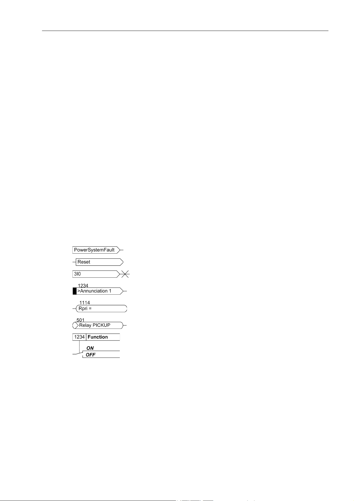
The following symbols are used in drawings:
Device-internal logical input signal
Device-internal logical output signal
Internal input signal of an analog quantity
External binary input signal with number (binary input,
input indication)
External binary output signal with number
(example of a value indication)
External binary output signal with number (device indication) used as
input signal
Example of a parameter switch designated FUNCTION with address
1234 and the possible settings ON and OFF
SIPROTEC, 7SD5, Manual
C53000-G1176-C169-5, Release date 02.2011
7
Page 8
Preface
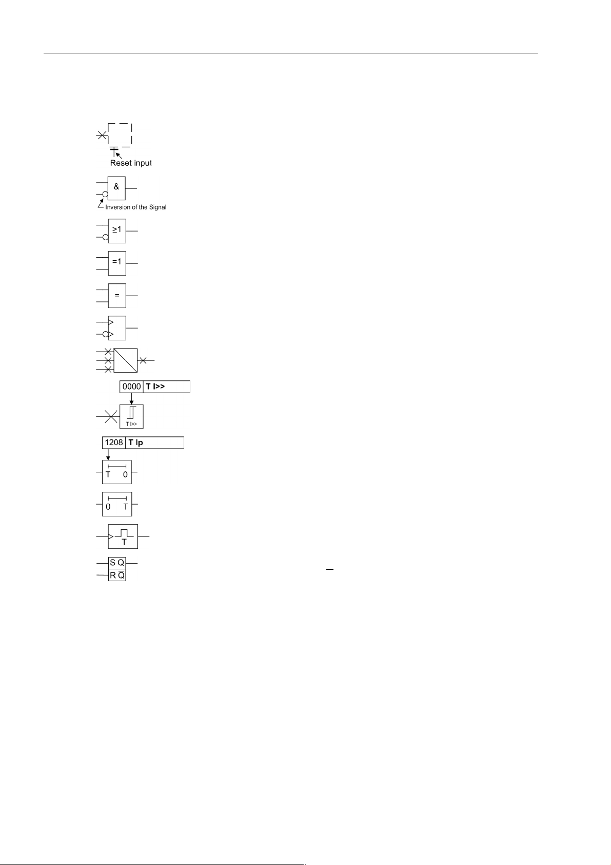
Besides these, graphical symbols are used in accordance with IEC 60617-12 and IEC 60617-13 or similar.
Some of the most frequently used are listed below:
Analog input values
AND-gate operation of input values
OR-gate operation of input values
Exclusive OR gate (antivalence): output is active, if only one of the
inputs is active
Coincidence gate: output is active, if both inputs are active or inactive
at the same time
Dynamic inputs (edge-triggered) above with positive, below with negative edge
Formation of one analog output signal from a number of analog input
signals
Limit stage with setting address and parameter designator (name)
Timer (pickup delay T, example adjustable) with setting address and
parameter designator (name)
Timer (dropout delay T, example non-adjustable)
Dynamic triggered pulse timer T (monoflop)
Static memory (RS-flipflop) with setting input (S), resetting input (R),
output (Q) and inverted output (Q
)
■
8
C53000-G1176-C169-5, Release date 02.2011
SIPROTEC, 7SD5, Manual
Page 9

Contents
1 Introduction. . . . . . . . . . . . . . . . . . . . . . . . . . . . . . . . . . . . . . . . . . . . . . . . . . . . . . . . . . . . . . . . . . . . . . . . . . . . . .21
1.1 Overall Operation. . . . . . . . . . . . . . . . . . . . . . . . . . . . . . . . . . . . . . . . . . . . . . . . . . . . . . . . . . . . . . . . . .22
1.2 Application Scope . . . . . . . . . . . . . . . . . . . . . . . . . . . . . . . . . . . . . . . . . . . . . . . . . . . . . . . . . . . . . . . . .25
1.3 Characteristics. . . . . . . . . . . . . . . . . . . . . . . . . . . . . . . . . . . . . . . . . . . . . . . . . . . . . . . . . . . . . . . . . . . .28
2 Functions. . . . . . . . . . . . . . . . . . . . . . . . . . . . . . . . . . . . . . . . . . . . . . . . . . . . . . . . . . . . . . . . . . . . . . . . . . . . . . . .35
2.1 General . . . . . . . . . . . . . . . . . . . . . . . . . . . . . . . . . . . . . . . . . . . . . . . . . . . . . . . . . . . . . . . . . . . . . . . . .37
2.1.1 Functional Scope . . . . . . . . . . . . . . . . . . . . . . . . . . . . . . . . . . . . . . . . . . . . . . . . . . . . . . . . . . . . . . .37
2.1.1.1 Configuration of the Scope of Functions . . . . . . . . . . . . . . . . . . . . . . . . . . . . . . . . . . . . . . . . . .37
2.1.1.2 Control of the Main Protection Functions . . . . . . . . . . . . . . . . . . . . . . . . . . . . . . . . . . . . . . . . . .38
2.1.1.3 Setting Notes . . . . . . . . . . . . . . . . . . . . . . . . . . . . . . . . . . . . . . . . . . . . . . . . . . . . . . . . . . . . . . .38
2.1.1.4 Settings . . . . . . . . . . . . . . . . . . . . . . . . . . . . . . . . . . . . . . . . . . . . . . . . . . . . . . . . . . . . . . . . . . .42
2.1.2 General Power System Data (Power System Data 1) . . . . . . . . . . . . . . . . . . . . . . . . . . . . . . . . . . .44
2.1.2.1 Setting Notes . . . . . . . . . . . . . . . . . . . . . . . . . . . . . . . . . . . . . . . . . . . . . . . . . . . . . . . . . . . . . . .44
2.1.2.2 Settings . . . . . . . . . . . . . . . . . . . . . . . . . . . . . . . . . . . . . . . . . . . . . . . . . . . . . . . . . . . . . . . . . . .53
2.1.3 Change Group . . . . . . . . . . . . . . . . . . . . . . . . . . . . . . . . . . . . . . . . . . . . . . . . . . . . . . . . . . . . . . . . .54
2.1.3.1 Purpose of the Setting Groups. . . . . . . . . . . . . . . . . . . . . . . . . . . . . . . . . . . . . . . . . . . . . . . . . .54
2.1.3.2 Setting Notes . . . . . . . . . . . . . . . . . . . . . . . . . . . . . . . . . . . . . . . . . . . . . . . . . . . . . . . . . . . . . . .54
2.1.3.3 Settings . . . . . . . . . . . . . . . . . . . . . . . . . . . . . . . . . . . . . . . . . . . . . . . . . . . . . . . . . . . . . . . . . . .55
2.1.3.4 Information List. . . . . . . . . . . . . . . . . . . . . . . . . . . . . . . . . . . . . . . . . . . . . . . . . . . . . . . . . . . . . .55
2.1.4 General Protection Data (Power System Data 2) . . . . . . . . . . . . . . . . . . . . . . . . . . . . . . . . . . . . . .55
2.1.4.1 Setting Notes . . . . . . . . . . . . . . . . . . . . . . . . . . . . . . . . . . . . . . . . . . . . . . . . . . . . . . . . . . . . . . .55
2.1.4.2 Settings . . . . . . . . . . . . . . . . . . . . . . . . . . . . . . . . . . . . . . . . . . . . . . . . . . . . . . . . . . . . . . . . . . .68
2.1.4.3 Information List. . . . . . . . . . . . . . . . . . . . . . . . . . . . . . . . . . . . . . . . . . . . . . . . . . . . . . . . . . . . . .72
2.2 Protection Data Interfaces and Protection Data Topology . . . . . . . . . . . . . . . . . . . . . . . . . . . . . . . . . . .74
2.2.1 Functional Description . . . . . . . . . . . . . . . . . . . . . . . . . . . . . . . . . . . . . . . . . . . . . . . . . . . . . . . . . . .74
2.2.1.1 Protection Data Topology / Protection Data Communication . . . . . . . . . . . . . . . . . . . . . . . . . . .74
2.2.2 Operating Modes of the Differential Protection . . . . . . . . . . . . . . . . . . . . . . . . . . . . . . . . . . . . . . . .79
2.2.2.1 Mode: Log Out Device . . . . . . . . . . . . . . . . . . . . . . . . . . . . . . . . . . . . . . . . . . . . . . . . . . . . . . . .79
2.2.2.2 Differential Protection Test Mode . . . . . . . . . . . . . . . . . . . . . . . . . . . . . . . . . . . . . . . . . . . . . . . .81
2.2.2.3 Differential Protection Commissioning Mode . . . . . . . . . . . . . . . . . . . . . . . . . . . . . . . . . . . . . . .83
2.2.3 Protection Data Interfaces . . . . . . . . . . . . . . . . . . . . . . . . . . . . . . . . . . . . . . . . . . . . . . . . . . . . . . . .84
2.2.3.1 Setting Notes . . . . . . . . . . . . . . . . . . . . . . . . . . . . . . . . . . . . . . . . . . . . . . . . . . . . . . . . . . . . . . .84
2.2.3.2 Settings . . . . . . . . . . . . . . . . . . . . . . . . . . . . . . . . . . . . . . . . . . . . . . . . . . . . . . . . . . . . . . . . . . .88
2.2.3.3 Information List. . . . . . . . . . . . . . . . . . . . . . . . . . . . . . . . . . . . . . . . . . . . . . . . . . . . . . . . . . . . . .89
2.2.4 Differential Protection Topology . . . . . . . . . . . . . . . . . . . . . . . . . . . . . . . . . . . . . . . . . . . . . . . . . . . .90
2.2.4.1 Setting Notes . . . . . . . . . . . . . . . . . . . . . . . . . . . . . . . . . . . . . . . . . . . . . . . . . . . . . . . . . . . . . . .90
2.2.4.2 Settings . . . . . . . . . . . . . . . . . . . . . . . . . . . . . . . . . . . . . . . . . . . . . . . . . . . . . . . . . . . . . . . . . . .92
2.2.4.3 Information List. . . . . . . . . . . . . . . . . . . . . . . . . . . . . . . . . . . . . . . . . . . . . . . . . . . . . . . . . . . . . .92
SIPROTEC, 7SD5, Manual
C53000-G1176-C169-5, Release date 02.2011
9
Page 10

Contents
2.3 Differential Protection . . . . . . . . . . . . . . . . . . . . . . . . . . . . . . . . . . . . . . . . . . . . . . . . . . . . . . . . . . . . . . 93
2.3.1 Functional Description. . . . . . . . . . . . . . . . . . . . . . . . . . . . . . . . . . . . . . . . . . . . . . . . . . . . . . . . . . . 93
2.3.2 Setting Notes. . . . . . . . . . . . . . . . . . . . . . . . . . . . . . . . . . . . . . . . . . . . . . . . . . . . . . . . . . . . . . . . . 103
2.3.3 Settings . . . . . . . . . . . . . . . . . . . . . . . . . . . . . . . . . . . . . . . . . . . . . . . . . . . . . . . . . . . . . . . . . . . . . 107
2.3.4 Information List . . . . . . . . . . . . . . . . . . . . . . . . . . . . . . . . . . . . . . . . . . . . . . . . . . . . . . . . . . . . . . . 108
2.4 Breaker Intertrip and Remote Tripping . . . . . . . . . . . . . . . . . . . . . . . . . . . . . . . . . . . . . . . . . . . . . . . . 110
2.4.1 Functional Description. . . . . . . . . . . . . . . . . . . . . . . . . . . . . . . . . . . . . . . . . . . . . . . . . . . . . . . . . . 110
2.4.2 Setting Notes. . . . . . . . . . . . . . . . . . . . . . . . . . . . . . . . . . . . . . . . . . . . . . . . . . . . . . . . . . . . . . . . . 113
2.4.3 Settings . . . . . . . . . . . . . . . . . . . . . . . . . . . . . . . . . . . . . . . . . . . . . . . . . . . . . . . . . . . . . . . . . . . . . 113
2.4.4 Information List . . . . . . . . . . . . . . . . . . . . . . . . . . . . . . . . . . . . . . . . . . . . . . . . . . . . . . . . . . . . . . . 114
2.5 Distance Protection . . . . . . . . . . . . . . . . . . . . . . . . . . . . . . . . . . . . . . . . . . . . . . . . . . . . . . . . . . . . . . 115
2.5.1 Distance Protection, General Settings. . . . . . . . . . . . . . . . . . . . . . . . . . . . . . . . . . . . . . . . . . . . . . 115
2.5.1.1 Earth Fault Detection . . . . . . . . . . . . . . . . . . . . . . . . . . . . . . . . . . . . . . . . . . . . . . . . . . . . . . . . 115
2.5.1.2 Pickup (optional) . . . . . . . . . . . . . . . . . . . . . . . . . . . . . . . . . . . . . . . . . . . . . . . . . . . . . . . . . . . 119
2.5.1.3 Calculation of the Impedances . . . . . . . . . . . . . . . . . . . . . . . . . . . . . . . . . . . . . . . . . . . . . . . . 124
2.5.1.4 Setting Notes . . . . . . . . . . . . . . . . . . . . . . . . . . . . . . . . . . . . . . . . . . . . . . . . . . . . . . . . . . . . . . 132
2.5.1.5 Settings . . . . . . . . . . . . . . . . . . . . . . . . . . . . . . . . . . . . . . . . . . . . . . . . . . . . . . . . . . . . . . . . . . 141
2.5.1.6 Information List . . . . . . . . . . . . . . . . . . . . . . . . . . . . . . . . . . . . . . . . . . . . . . . . . . . . . . . . . . . . 144
2.5.2 Distance Protection with Quadrilateral Characteristic (optional) . . . . . . . . . . . . . . . . . . . . . . . . . . 146
2.5.2.1 Method of Operation . . . . . . . . . . . . . . . . . . . . . . . . . . . . . . . . . . . . . . . . . . . . . . . . . . . . . . . . 146
2.5.2.2 Setting Notes . . . . . . . . . . . . . . . . . . . . . . . . . . . . . . . . . . . . . . . . . . . . . . . . . . . . . . . . . . . . . . 152
2.5.2.3 Settings . . . . . . . . . . . . . . . . . . . . . . . . . . . . . . . . . . . . . . . . . . . . . . . . . . . . . . . . . . . . . . . . . . 160
2.5.3 Distance Protection with MHO Characteristic (optional) . . . . . . . . . . . . . . . . . . . . . . . . . . . . . . . . 163
2.5.3.1 Functional Description . . . . . . . . . . . . . . . . . . . . . . . . . . . . . . . . . . . . . . . . . . . . . . . . . . . . . . . 163
2.5.3.2 Setting Notes . . . . . . . . . . . . . . . . . . . . . . . . . . . . . . . . . . . . . . . . . . . . . . . . . . . . . . . . . . . . . . 170
2.5.3.3 Settings . . . . . . . . . . . . . . . . . . . . . . . . . . . . . . . . . . . . . . . . . . . . . . . . . . . . . . . . . . . . . . . . . . 174
2.5.4 Tripping Logic of the Distance Protection . . . . . . . . . . . . . . . . . . . . . . . . . . . . . . . . . . . . . . . . . . . 176
2.5.4.1 Method of Operation . . . . . . . . . . . . . . . . . . . . . . . . . . . . . . . . . . . . . . . . . . . . . . . . . . . . . . . . 176
2.5.4.2 Setting Notes . . . . . . . . . . . . . . . . . . . . . . . . . . . . . . . . . . . . . . . . . . . . . . . . . . . . . . . . . . . . . . 180
2.6 Power Swing Detection (optional). . . . . . . . . . . . . . . . . . . . . . . . . . . . . . . . . . . . . . . . . . . . . . . . . . . . 181
2.6.1 General . . . . . . . . . . . . . . . . . . . . . . . . . . . . . . . . . . . . . . . . . . . . . . . . . . . . . . . . . . . . . . . . . . . . . 181
2.6.2 Method of Operation . . . . . . . . . . . . . . . . . . . . . . . . . . . . . . . . . . . . . . . . . . . . . . . . . . . . . . . . . . . 182
2.6.3 Setting Notes. . . . . . . . . . . . . . . . . . . . . . . . . . . . . . . . . . . . . . . . . . . . . . . . . . . . . . . . . . . . . . . . . 185
2.6.4 Settings . . . . . . . . . . . . . . . . . . . . . . . . . . . . . . . . . . . . . . . . . . . . . . . . . . . . . . . . . . . . . . . . . . . . . 186
2.6.5 Information List . . . . . . . . . . . . . . . . . . . . . . . . . . . . . . . . . . . . . . . . . . . . . . . . . . . . . . . . . . . . . . . 186
10
C53000-G1176-C169-5, Release date 02.2011
SIPROTEC, 7SD5, Manual
Page 11

Contents
2.7 Teleprotection for Distance Protection (optional) . . . . . . . . . . . . . . . . . . . . . . . . . . . . . . . . . . . . . . . . .187
2.7.1 General . . . . . . . . . . . . . . . . . . . . . . . . . . . . . . . . . . . . . . . . . . . . . . . . . . . . . . . . . . . . . . . . . . . . .187
2.7.2 Method of Operation . . . . . . . . . . . . . . . . . . . . . . . . . . . . . . . . . . . . . . . . . . . . . . . . . . . . . . . . . . .188
2.7.3 PUTT (Pickup) . . . . . . . . . . . . . . . . . . . . . . . . . . . . . . . . . . . . . . . . . . . . . . . . . . . . . . . . . . . . . . . .189
2.7.4 Permissive Underreach Transfer Trip with Zone Acceleration Z1B (PUTT). . . . . . . . . . . . . . . . . .191
2.7.5 Direct Underreach Transfer Trip. . . . . . . . . . . . . . . . . . . . . . . . . . . . . . . . . . . . . . . . . . . . . . . . . . .193
2.7.6 Permissive Overreach Transfer Trip (POTT) . . . . . . . . . . . . . . . . . . . . . . . . . . . . . . . . . . . . . . . . .194
2.7.7 Directional Comparison . . . . . . . . . . . . . . . . . . . . . . . . . . . . . . . . . . . . . . . . . . . . . . . . . . . . . . . . .197
2.7.8 Unblocking Scheme . . . . . . . . . . . . . . . . . . . . . . . . . . . . . . . . . . . . . . . . . . . . . . . . . . . . . . . . . . . .199
2.7.9 Blocking Scheme . . . . . . . . . . . . . . . . . . . . . . . . . . . . . . . . . . . . . . . . . . . . . . . . . . . . . . . . . . . . . .203
2.7.10 Pilot Wire Comparison . . . . . . . . . . . . . . . . . . . . . . . . . . . . . . . . . . . . . . . . . . . . . . . . . . . . . . . . . .206
2.7.11 Reverse Interlocking . . . . . . . . . . . . . . . . . . . . . . . . . . . . . . . . . . . . . . . . . . . . . . . . . . . . . . . . . . .209
2.7.12 Transient Blocking . . . . . . . . . . . . . . . . . . . . . . . . . . . . . . . . . . . . . . . . . . . . . . . . . . . . . . . . . . . . .210
2.7.13 Measures for Weak or Zero Infeed . . . . . . . . . . . . . . . . . . . . . . . . . . . . . . . . . . . . . . . . . . . . . . . .211
2.7.14 Setting Notes . . . . . . . . . . . . . . . . . . . . . . . . . . . . . . . . . . . . . . . . . . . . . . . . . . . . . . . . . . . . . . . . .212
2.7.15 Settings . . . . . . . . . . . . . . . . . . . . . . . . . . . . . . . . . . . . . . . . . . . . . . . . . . . . . . . . . . . . . . . . . . . . .215
2.7.16 Information List. . . . . . . . . . . . . . . . . . . . . . . . . . . . . . . . . . . . . . . . . . . . . . . . . . . . . . . . . . . . . . . .215
2.8 Earth Fault Protection in Earthed Systems (optional) . . . . . . . . . . . . . . . . . . . . . . . . . . . . . . . . . . . . .217
2.8.1 Functional Description . . . . . . . . . . . . . . . . . . . . . . . . . . . . . . . . . . . . . . . . . . . . . . . . . . . . . . . . . .217
2.8.2 Setting Notes . . . . . . . . . . . . . . . . . . . . . . . . . . . . . . . . . . . . . . . . . . . . . . . . . . . . . . . . . . . . . . . . .234
2.8.3 Settings . . . . . . . . . . . . . . . . . . . . . . . . . . . . . . . . . . . . . . . . . . . . . . . . . . . . . . . . . . . . . . . . . . . . .244
2.8.4 Information List. . . . . . . . . . . . . . . . . . . . . . . . . . . . . . . . . . . . . . . . . . . . . . . . . . . . . . . . . . . . . . . .248
2.9 Teleprotection for Earth Fault Protection (optional) . . . . . . . . . . . . . . . . . . . . . . . . . . . . . . . . . . . . . . .249
2.9.1 General . . . . . . . . . . . . . . . . . . . . . . . . . . . . . . . . . . . . . . . . . . . . . . . . . . . . . . . . . . . . . . . . . . . . .249
2.9.2 Directional Comparison Pickup . . . . . . . . . . . . . . . . . . . . . . . . . . . . . . . . . . . . . . . . . . . . . . . . . . .250
2.9.3 Directional Unblocking Scheme . . . . . . . . . . . . . . . . . . . . . . . . . . . . . . . . . . . . . . . . . . . . . . . . . . .253
2.9.4 Directional Blocking Scheme . . . . . . . . . . . . . . . . . . . . . . . . . . . . . . . . . . . . . . . . . . . . . . . . . . . . .257
2.9.5 Transient Blocking . . . . . . . . . . . . . . . . . . . . . . . . . . . . . . . . . . . . . . . . . . . . . . . . . . . . . . . . . . . . .259
2.9.6 Measures for Weak or Zero Infeed . . . . . . . . . . . . . . . . . . . . . . . . . . . . . . . . . . . . . . . . . . . . . . . .260
2.9.7 Setting Notes . . . . . . . . . . . . . . . . . . . . . . . . . . . . . . . . . . . . . . . . . . . . . . . . . . . . . . . . . . . . . . . . .261
2.9.8 Settings . . . . . . . . . . . . . . . . . . . . . . . . . . . . . . . . . . . . . . . . . . . . . . . . . . . . . . . . . . . . . . . . . . . . .263
2.9.9 Information List. . . . . . . . . . . . . . . . . . . . . . . . . . . . . . . . . . . . . . . . . . . . . . . . . . . . . . . . . . . . . . . .264
2.10 Restricted Earth Fault Protection (optional). . . . . . . . . . . . . . . . . . . . . . . . . . . . . . . . . . . . . . . . . . . . .265
2.10.1 Application Examples. . . . . . . . . . . . . . . . . . . . . . . . . . . . . . . . . . . . . . . . . . . . . . . . . . . . . . . . . . .265
2.10.2 Functional Description . . . . . . . . . . . . . . . . . . . . . . . . . . . . . . . . . . . . . . . . . . . . . . . . . . . . . . . . . .266
2.10.3 Setting Notes . . . . . . . . . . . . . . . . . . . . . . . . . . . . . . . . . . . . . . . . . . . . . . . . . . . . . . . . . . . . . . . . .271
2.10.4 Settings . . . . . . . . . . . . . . . . . . . . . . . . . . . . . . . . . . . . . . . . . . . . . . . . . . . . . . . . . . . . . . . . . . . . .272
2.10.5 Information List. . . . . . . . . . . . . . . . . . . . . . . . . . . . . . . . . . . . . . . . . . . . . . . . . . . . . . . . . . . . . . . .272
SIPROTEC, 7SD5, Manual
C53000-G1176-C169-5, Release date 02.2011
11
Page 12

Contents
2.11 Measures for Weak and Zero Infeed. . . . . . . . . . . . . . . . . . . . . . . . . . . . . . . . . . . . . . . . . . . . . . . . . . 273
2.11.1 Echo Function . . . . . . . . . . . . . . . . . . . . . . . . . . . . . . . . . . . . . . . . . . . . . . . . . . . . . . . . . . . . . . . . 273
2.11.1.1 Function Description . . . . . . . . . . . . . . . . . . . . . . . . . . . . . . . . . . . . . . . . . . . . . . . . . . . . . . . . 273
2.11.2 Classical Tripping . . . . . . . . . . . . . . . . . . . . . . . . . . . . . . . . . . . . . . . . . . . . . . . . . . . . . . . . . . . . . 275
2.11.2.1 Method of Operation . . . . . . . . . . . . . . . . . . . . . . . . . . . . . . . . . . . . . . . . . . . . . . . . . . . . . . . . 275
2.11.2.2 Setting Notes . . . . . . . . . . . . . . . . . . . . . . . . . . . . . . . . . . . . . . . . . . . . . . . . . . . . . . . . . . . . . . 277
2.11.3 Tripping According to French Specification . . . . . . . . . . . . . . . . . . . . . . . . . . . . . . . . . . . . . . . . . . 278
2.11.3.1 Functional Description . . . . . . . . . . . . . . . . . . . . . . . . . . . . . . . . . . . . . . . . . . . . . . . . . . . . . . . 278
2.11.3.2 Setting Notes . . . . . . . . . . . . . . . . . . . . . . . . . . . . . . . . . . . . . . . . . . . . . . . . . . . . . . . . . . . . . . 281
2.11.4 Tables on Classical Tripping and Tripping according to French Specification) . . . . . . . . . . . . . . . 283
2.11.4.1 Settings . . . . . . . . . . . . . . . . . . . . . . . . . . . . . . . . . . . . . . . . . . . . . . . . . . . . . . . . . . . . . . . . . . 283
2.11.4.2 Information List . . . . . . . . . . . . . . . . . . . . . . . . . . . . . . . . . . . . . . . . . . . . . . . . . . . . . . . . . . . . 284
2.12 Direct Local Trip . . . . . . . . . . . . . . . . . . . . . . . . . . . . . . . . . . . . . . . . . . . . . . . . . . . . . . . . . . . . . . . . . 285
2.12.1 Functional Description. . . . . . . . . . . . . . . . . . . . . . . . . . . . . . . . . . . . . . . . . . . . . . . . . . . . . . . . . . 285
2.12.2 Setting Notes. . . . . . . . . . . . . . . . . . . . . . . . . . . . . . . . . . . . . . . . . . . . . . . . . . . . . . . . . . . . . . . . . 286
2.12.3 Settings . . . . . . . . . . . . . . . . . . . . . . . . . . . . . . . . . . . . . . . . . . . . . . . . . . . . . . . . . . . . . . . . . . . . . 286
2.12.4 Information List . . . . . . . . . . . . . . . . . . . . . . . . . . . . . . . . . . . . . . . . . . . . . . . . . . . . . . . . . . . . . . . 286
2.13 Transmission of Binary Commands and Messages . . . . . . . . . . . . . . . . . . . . . . . . . . . . . . . . . . . . . . 287
2.13.1 Functional Description. . . . . . . . . . . . . . . . . . . . . . . . . . . . . . . . . . . . . . . . . . . . . . . . . . . . . . . . . . 287
2.13.2 Information List . . . . . . . . . . . . . . . . . . . . . . . . . . . . . . . . . . . . . . . . . . . . . . . . . . . . . . . . . . . . . . . 288
2.14 Instantaneous High-Current Switch-onto-Fault Protection (SOTF). . . . . . . . . . . . . . . . . . . . . . . . . . . 290
2.14.1 Functional Description. . . . . . . . . . . . . . . . . . . . . . . . . . . . . . . . . . . . . . . . . . . . . . . . . . . . . . . . . . 290
2.14.2 Setting Notes. . . . . . . . . . . . . . . . . . . . . . . . . . . . . . . . . . . . . . . . . . . . . . . . . . . . . . . . . . . . . . . . . 292
2.14.3 Settings . . . . . . . . . . . . . . . . . . . . . . . . . . . . . . . . . . . . . . . . . . . . . . . . . . . . . . . . . . . . . . . . . . . . . 294
2.14.4 Information List . . . . . . . . . . . . . . . . . . . . . . . . . . . . . . . . . . . . . . . . . . . . . . . . . . . . . . . . . . . . . . . 294
2.15 Sensitive Earth Flt.(comp/ isol. starp.) . . . . . . . . . . . . . . . . . . . . . . . . . . . . . . . . . . . . . . . . . . . . . . . . 295
2.15.1 Method of Operation . . . . . . . . . . . . . . . . . . . . . . . . . . . . . . . . . . . . . . . . . . . . . . . . . . . . . . . . . . . 295
2.15.2 Setting Notes. . . . . . . . . . . . . . . . . . . . . . . . . . . . . . . . . . . . . . . . . . . . . . . . . . . . . . . . . . . . . . . . . 298
2.15.3 Settings . . . . . . . . . . . . . . . . . . . . . . . . . . . . . . . . . . . . . . . . . . . . . . . . . . . . . . . . . . . . . . . . . . . . . 301
2.15.4 Information List . . . . . . . . . . . . . . . . . . . . . . . . . . . . . . . . . . . . . . . . . . . . . . . . . . . . . . . . . . . . . . . 301
2.16 Backup Time Overcurrent Protection . . . . . . . . . . . . . . . . . . . . . . . . . . . . . . . . . . . . . . . . . . . . . . . . . 302
2.16.1 General . . . . . . . . . . . . . . . . . . . . . . . . . . . . . . . . . . . . . . . . . . . . . . . . . . . . . . . . . . . . . . . . . . . . . 302
2.16.2 Functional Description. . . . . . . . . . . . . . . . . . . . . . . . . . . . . . . . . . . . . . . . . . . . . . . . . . . . . . . . . . 303
2.16.3 Setting Notes. . . . . . . . . . . . . . . . . . . . . . . . . . . . . . . . . . . . . . . . . . . . . . . . . . . . . . . . . . . . . . . . . 309
2.16.4 Settings . . . . . . . . . . . . . . . . . . . . . . . . . . . . . . . . . . . . . . . . . . . . . . . . . . . . . . . . . . . . . . . . . . . . . 315
2.16.5 Information List . . . . . . . . . . . . . . . . . . . . . . . . . . . . . . . . . . . . . . . . . . . . . . . . . . . . . . . . . . . . . . . 316
2.17 Automatic Reclosure Function (optional) . . . . . . . . . . . . . . . . . . . . . . . . . . . . . . . . . . . . . . . . . . . . . . 318
2.17.1 Functional Description. . . . . . . . . . . . . . . . . . . . . . . . . . . . . . . . . . . . . . . . . . . . . . . . . . . . . . . . . . 318
2.17.2 Setting Notes. . . . . . . . . . . . . . . . . . . . . . . . . . . . . . . . . . . . . . . . . . . . . . . . . . . . . . . . . . . . . . . . . 335
2.17.3 Settings . . . . . . . . . . . . . . . . . . . . . . . . . . . . . . . . . . . . . . . . . . . . . . . . . . . . . . . . . . . . . . . . . . . . . 343
2.17.4 Information List . . . . . . . . . . . . . . . . . . . . . . . . . . . . . . . . . . . . . . . . . . . . . . . . . . . . . . . . . . . . . . . 346
2.18 Synchronism and Voltage Check (optional) . . . . . . . . . . . . . . . . . . . . . . . . . . . . . . . . . . . . . . . . . . . . 348
2.18.1 Method of Operation . . . . . . . . . . . . . . . . . . . . . . . . . . . . . . . . . . . . . . . . . . . . . . . . . . . . . . . . . . . 348
2.18.2 Setting Notes. . . . . . . . . . . . . . . . . . . . . . . . . . . . . . . . . . . . . . . . . . . . . . . . . . . . . . . . . . . . . . . . . 354
2.18.3 Settings . . . . . . . . . . . . . . . . . . . . . . . . . . . . . . . . . . . . . . . . . . . . . . . . . . . . . . . . . . . . . . . . . . . . . 358
2.18.4 Information List . . . . . . . . . . . . . . . . . . . . . . . . . . . . . . . . . . . . . . . . . . . . . . . . . . . . . . . . . . . . . . . 360
12
C53000-G1176-C169-5, Release date 02.2011
SIPROTEC, 7SD5, Manual
Page 13

Contents
2.19 Undervoltage and Overvoltage Protection (optional). . . . . . . . . . . . . . . . . . . . . . . . . . . . . . . . . . . . . .361
2.19.1 Overvoltage protection. . . . . . . . . . . . . . . . . . . . . . . . . . . . . . . . . . . . . . . . . . . . . . . . . . . . . . . . . .361
2.19.2 Undervoltage protection. . . . . . . . . . . . . . . . . . . . . . . . . . . . . . . . . . . . . . . . . . . . . . . . . . . . . . . . .368
2.19.3 Setting Notes . . . . . . . . . . . . . . . . . . . . . . . . . . . . . . . . . . . . . . . . . . . . . . . . . . . . . . . . . . . . . . . . .372
2.19.4 Settings . . . . . . . . . . . . . . . . . . . . . . . . . . . . . . . . . . . . . . . . . . . . . . . . . . . . . . . . . . . . . . . . . . . . .376
2.19.5 Information List. . . . . . . . . . . . . . . . . . . . . . . . . . . . . . . . . . . . . . . . . . . . . . . . . . . . . . . . . . . . . . . .378
2.20 Frequency Protection (optional). . . . . . . . . . . . . . . . . . . . . . . . . . . . . . . . . . . . . . . . . . . . . . . . . . . . . .381
2.20.1 Method of Operation . . . . . . . . . . . . . . . . . . . . . . . . . . . . . . . . . . . . . . . . . . . . . . . . . . . . . . . . . . .381
2.20.2 Setting Notes . . . . . . . . . . . . . . . . . . . . . . . . . . . . . . . . . . . . . . . . . . . . . . . . . . . . . . . . . . . . . . . . .384
2.20.3 Settings . . . . . . . . . . . . . . . . . . . . . . . . . . . . . . . . . . . . . . . . . . . . . . . . . . . . . . . . . . . . . . . . . . . . .385
2.20.4 Information List. . . . . . . . . . . . . . . . . . . . . . . . . . . . . . . . . . . . . . . . . . . . . . . . . . . . . . . . . . . . . . . .386
2.21 Fault Locator . . . . . . . . . . . . . . . . . . . . . . . . . . . . . . . . . . . . . . . . . . . . . . . . . . . . . . . . . . . . . . . . . . . .387
2.21.1 Functional Description . . . . . . . . . . . . . . . . . . . . . . . . . . . . . . . . . . . . . . . . . . . . . . . . . . . . . . . . . .387
2.21.2 Setting Notes . . . . . . . . . . . . . . . . . . . . . . . . . . . . . . . . . . . . . . . . . . . . . . . . . . . . . . . . . . . . . . . . .391
2.21.3 Settings . . . . . . . . . . . . . . . . . . . . . . . . . . . . . . . . . . . . . . . . . . . . . . . . . . . . . . . . . . . . . . . . . . . . .394
2.21.4 Information List. . . . . . . . . . . . . . . . . . . . . . . . . . . . . . . . . . . . . . . . . . . . . . . . . . . . . . . . . . . . . . . .395
2.22 Circuit Breaker Failure Protection . . . . . . . . . . . . . . . . . . . . . . . . . . . . . . . . . . . . . . . . . . . . . . . . . . . .396
2.22.1 Functional Description . . . . . . . . . . . . . . . . . . . . . . . . . . . . . . . . . . . . . . . . . . . . . . . . . . . . . . . . . .396
2.22.2 Setting Notes . . . . . . . . . . . . . . . . . . . . . . . . . . . . . . . . . . . . . . . . . . . . . . . . . . . . . . . . . . . . . . . . .408
2.22.3 Settings . . . . . . . . . . . . . . . . . . . . . . . . . . . . . . . . . . . . . . . . . . . . . . . . . . . . . . . . . . . . . . . . . . . . .412
2.22.4 Information List. . . . . . . . . . . . . . . . . . . . . . . . . . . . . . . . . . . . . . . . . . . . . . . . . . . . . . . . . . . . . . . .413
2.23 Thermal Overload Protection. . . . . . . . . . . . . . . . . . . . . . . . . . . . . . . . . . . . . . . . . . . . . . . . . . . . . . . .414
2.23.1 Method of Operation . . . . . . . . . . . . . . . . . . . . . . . . . . . . . . . . . . . . . . . . . . . . . . . . . . . . . . . . . . .414
2.23.2 Setting Notes . . . . . . . . . . . . . . . . . . . . . . . . . . . . . . . . . . . . . . . . . . . . . . . . . . . . . . . . . . . . . . . . .415
2.23.3 Settings . . . . . . . . . . . . . . . . . . . . . . . . . . . . . . . . . . . . . . . . . . . . . . . . . . . . . . . . . . . . . . . . . . . . .417
2.23.4 Information List. . . . . . . . . . . . . . . . . . . . . . . . . . . . . . . . . . . . . . . . . . . . . . . . . . . . . . . . . . . . . . . .417
2.24 Monitoring Functions . . . . . . . . . . . . . . . . . . . . . . . . . . . . . . . . . . . . . . . . . . . . . . . . . . . . . . . . . . . . . .418
2.24.1 Measurement Supervision . . . . . . . . . . . . . . . . . . . . . . . . . . . . . . . . . . . . . . . . . . . . . . . . . . . . . . .418
2.24.1.1 Hardware Monitoring . . . . . . . . . . . . . . . . . . . . . . . . . . . . . . . . . . . . . . . . . . . . . . . . . . . . . . . .418
2.24.1.2 Software Monitoring . . . . . . . . . . . . . . . . . . . . . . . . . . . . . . . . . . . . . . . . . . . . . . . . . . . . . . . . .420
2.24.1.3 Measurement Circuit Monitoring . . . . . . . . . . . . . . . . . . . . . . . . . . . . . . . . . . . . . . . . . . . . . . .420
2.24.1.4 Monitoring the Phase Angle of the Positive Sequence Power . . . . . . . . . . . . . . . . . . . . . . . . .429
2.24.1.5 Fault Reactions . . . . . . . . . . . . . . . . . . . . . . . . . . . . . . . . . . . . . . . . . . . . . . . . . . . . . . . . . . . .432
2.24.1.6 Setting Notes . . . . . . . . . . . . . . . . . . . . . . . . . . . . . . . . . . . . . . . . . . . . . . . . . . . . . . . . . . . . . .435
2.24.1.7 Settings . . . . . . . . . . . . . . . . . . . . . . . . . . . . . . . . . . . . . . . . . . . . . . . . . . . . . . . . . . . . . . . . . .437
2.24.1.8 Information List. . . . . . . . . . . . . . . . . . . . . . . . . . . . . . . . . . . . . . . . . . . . . . . . . . . . . . . . . . . . .438
2.24.2 Trip Circuit Supervision . . . . . . . . . . . . . . . . . . . . . . . . . . . . . . . . . . . . . . . . . . . . . . . . . . . . . . . . .439
2.24.2.1 Functional Description . . . . . . . . . . . . . . . . . . . . . . . . . . . . . . . . . . . . . . . . . . . . . . . . . . . . . . .439
2.24.2.2 Setting Notes . . . . . . . . . . . . . . . . . . . . . . . . . . . . . . . . . . . . . . . . . . . . . . . . . . . . . . . . . . . . . .442
2.24.2.3 Settings . . . . . . . . . . . . . . . . . . . . . . . . . . . . . . . . . . . . . . . . . . . . . . . . . . . . . . . . . . . . . . . . . .442
2.24.2.4 Information List. . . . . . . . . . . . . . . . . . . . . . . . . . . . . . . . . . . . . . . . . . . . . . . . . . . . . . . . . . . . .442
SIPROTEC, 7SD5, Manual
C53000-G1176-C169-5, Release date 02.2011
13
Page 14

Contents
2.25 Function Control and Circuit Breaker Test . . . . . . . . . . . . . . . . . . . . . . . . . . . . . . . . . . . . . . . . . . . . . 443
2.25.1 Function Control . . . . . . . . . . . . . . . . . . . . . . . . . . . . . . . . . . . . . . . . . . . . . . . . . . . . . . . . . . . . . . 443
2.25.1.1 Line Energization Recognition . . . . . . . . . . . . . . . . . . . . . . . . . . . . . . . . . . . . . . . . . . . . . . . . . 443
2.25.1.2 Detection of the Circuit Breaker Position . . . . . . . . . . . . . . . . . . . . . . . . . . . . . . . . . . . . . . . . . 447
2.25.1.3 Open Pole Detector . . . . . . . . . . . . . . . . . . . . . . . . . . . . . . . . . . . . . . . . . . . . . . . . . . . . . . . . . 449
2.25.1.4 Pickup Logic of the Entire Device . . . . . . . . . . . . . . . . . . . . . . . . . . . . . . . . . . . . . . . . . . . . . . 451
2.25.1.5 Tripping Logic of the Entire Device . . . . . . . . . . . . . . . . . . . . . . . . . . . . . . . . . . . . . . . . . . . . . 452
2.25.2 Circuit Breaker Test . . . . . . . . . . . . . . . . . . . . . . . . . . . . . . . . . . . . . . . . . . . . . . . . . . . . . . . . . . . . 457
2.25.2.1 Functional Description . . . . . . . . . . . . . . . . . . . . . . . . . . . . . . . . . . . . . . . . . . . . . . . . . . . . . . . 457
2.25.2.2 Information List . . . . . . . . . . . . . . . . . . . . . . . . . . . . . . . . . . . . . . . . . . . . . . . . . . . . . . . . . . . . 458
2.25.3 Device . . . . . . . . . . . . . . . . . . . . . . . . . . . . . . . . . . . . . . . . . . . . . . . . . . . . . . . . . . . . . . . . . . . . . . 459
2.25.3.1 Command-Dependent Messages . . . . . . . . . . . . . . . . . . . . . . . . . . . . . . . . . . . . . . . . . . . . . . 459
2.25.3.2 Switching Statistics . . . . . . . . . . . . . . . . . . . . . . . . . . . . . . . . . . . . . . . . . . . . . . . . . . . . . . . . . 460
2.25.3.3 Setting Notes . . . . . . . . . . . . . . . . . . . . . . . . . . . . . . . . . . . . . . . . . . . . . . . . . . . . . . . . . . . . . . 460
2.25.3.4 Settings . . . . . . . . . . . . . . . . . . . . . . . . . . . . . . . . . . . . . . . . . . . . . . . . . . . . . . . . . . . . . . . . . . 461
2.25.3.5 Information List . . . . . . . . . . . . . . . . . . . . . . . . . . . . . . . . . . . . . . . . . . . . . . . . . . . . . . . . . . . . 461
2.25.4 EN100-Modul 1 . . . . . . . . . . . . . . . . . . . . . . . . . . . . . . . . . . . . . . . . . . . . . . . . . . . . . . . . . . . . . . . 463
2.25.4.1 Functional Description . . . . . . . . . . . . . . . . . . . . . . . . . . . . . . . . . . . . . . . . . . . . . . . . . . . . . . . 463
2.25.4.2 Setting Notes . . . . . . . . . . . . . . . . . . . . . . . . . . . . . . . . . . . . . . . . . . . . . . . . . . . . . . . . . . . . . . 463
2.25.4.3 Information List . . . . . . . . . . . . . . . . . . . . . . . . . . . . . . . . . . . . . . . . . . . . . . . . . . . . . . . . . . . . 463
14
C53000-G1176-C169-5, Release date 02.2011
SIPROTEC, 7SD5, Manual
Page 15

Contents
2.26 Additional Functions . . . . . . . . . . . . . . . . . . . . . . . . . . . . . . . . . . . . . . . . . . . . . . . . . . . . . . . . . . . . . .464
2.26.1 Commissioning Aid . . . . . . . . . . . . . . . . . . . . . . . . . . . . . . . . . . . . . . . . . . . . . . . . . . . . . . . . . . . .464
2.26.1.1 Functional Description . . . . . . . . . . . . . . . . . . . . . . . . . . . . . . . . . . . . . . . . . . . . . . . . . . . . . . .464
2.26.1.2 Setting Notes . . . . . . . . . . . . . . . . . . . . . . . . . . . . . . . . . . . . . . . . . . . . . . . . . . . . . . . . . . . . . .466
2.26.2 Processing of Messages . . . . . . . . . . . . . . . . . . . . . . . . . . . . . . . . . . . . . . . . . . . . . . . . . . . . . . . .467
2.26.2.1 Functional Description . . . . . . . . . . . . . . . . . . . . . . . . . . . . . . . . . . . . . . . . . . . . . . . . . . . . . . .467
2.26.3 Statistics. . . . . . . . . . . . . . . . . . . . . . . . . . . . . . . . . . . . . . . . . . . . . . . . . . . . . . . . . . . . . . . . . . . . .470
2.26.3.1 Function Description. . . . . . . . . . . . . . . . . . . . . . . . . . . . . . . . . . . . . . . . . . . . . . . . . . . . . . . . .470
2.26.3.2 Information List. . . . . . . . . . . . . . . . . . . . . . . . . . . . . . . . . . . . . . . . . . . . . . . . . . . . . . . . . . . . .471
2.26.4 Measurement During Operation. . . . . . . . . . . . . . . . . . . . . . . . . . . . . . . . . . . . . . . . . . . . . . . . . . .472
2.26.4.1 Functional Description . . . . . . . . . . . . . . . . . . . . . . . . . . . . . . . . . . . . . . . . . . . . . . . . . . . . . . .472
2.26.4.2 Information List. . . . . . . . . . . . . . . . . . . . . . . . . . . . . . . . . . . . . . . . . . . . . . . . . . . . . . . . . . . . .474
2.26.5 Differential Protection Values . . . . . . . . . . . . . . . . . . . . . . . . . . . . . . . . . . . . . . . . . . . . . . . . . . . . .476
2.26.5.1 Measured Values of the Differential Protection . . . . . . . . . . . . . . . . . . . . . . . . . . . . . . . . . . . .476
2.26.5.2 Information List. . . . . . . . . . . . . . . . . . . . . . . . . . . . . . . . . . . . . . . . . . . . . . . . . . . . . . . . . . . . .476
2.26.6 Measured Values Constellation . . . . . . . . . . . . . . . . . . . . . . . . . . . . . . . . . . . . . . . . . . . . . . . . . . .477
2.26.6.1 Functional Description . . . . . . . . . . . . . . . . . . . . . . . . . . . . . . . . . . . . . . . . . . . . . . . . . . . . . . .477
2.26.7 Oscillographic Fault Records . . . . . . . . . . . . . . . . . . . . . . . . . . . . . . . . . . . . . . . . . . . . . . . . . . . . .478
2.26.7.1 Functional Description . . . . . . . . . . . . . . . . . . . . . . . . . . . . . . . . . . . . . . . . . . . . . . . . . . . . . . .478
2.26.7.2 Setting Notes . . . . . . . . . . . . . . . . . . . . . . . . . . . . . . . . . . . . . . . . . . . . . . . . . . . . . . . . . . . . . .478
2.26.7.3 Settings . . . . . . . . . . . . . . . . . . . . . . . . . . . . . . . . . . . . . . . . . . . . . . . . . . . . . . . . . . . . . . . . . .479
2.26.7.4 Information List. . . . . . . . . . . . . . . . . . . . . . . . . . . . . . . . . . . . . . . . . . . . . . . . . . . . . . . . . . . . .479
2.26.8 Demand Measurement Setup . . . . . . . . . . . . . . . . . . . . . . . . . . . . . . . . . . . . . . . . . . . . . . . . . . . .480
2.26.8.1 Long-Term Average Values . . . . . . . . . . . . . . . . . . . . . . . . . . . . . . . . . . . . . . . . . . . . . . . . . . .480
2.26.8.2 Setting Notes . . . . . . . . . . . . . . . . . . . . . . . . . . . . . . . . . . . . . . . . . . . . . . . . . . . . . . . . . . . . . .480
2.26.8.3 Settings . . . . . . . . . . . . . . . . . . . . . . . . . . . . . . . . . . . . . . . . . . . . . . . . . . . . . . . . . . . . . . . . . .480
2.26.8.4 Information List. . . . . . . . . . . . . . . . . . . . . . . . . . . . . . . . . . . . . . . . . . . . . . . . . . . . . . . . . . . . .481
2.26.9 Min/Max Measurement Setup . . . . . . . . . . . . . . . . . . . . . . . . . . . . . . . . . . . . . . . . . . . . . . . . . . . .481
2.26.9.1 Reset . . . . . . . . . . . . . . . . . . . . . . . . . . . . . . . . . . . . . . . . . . . . . . . . . . . . . . . . . . . . . . . . . . . .481
2.26.9.2 Setting Notes . . . . . . . . . . . . . . . . . . . . . . . . . . . . . . . . . . . . . . . . . . . . . . . . . . . . . . . . . . . . . .481
2.26.9.3 Settings . . . . . . . . . . . . . . . . . . . . . . . . . . . . . . . . . . . . . . . . . . . . . . . . . . . . . . . . . . . . . . . . . .481
2.26.9.4 Information List. . . . . . . . . . . . . . . . . . . . . . . . . . . . . . . . . . . . . . . . . . . . . . . . . . . . . . . . . . . . .482
2.26.10 Set Points (Measured Values) . . . . . . . . . . . . . . . . . . . . . . . . . . . . . . . . . . . . . . . . . . . . . . . . . . . .483
2.26.10.1 Limit value monitoring . . . . . . . . . . . . . . . . . . . . . . . . . . . . . . . . . . . . . . . . . . . . . . . . . . . . . . .484
2.26.10.2 Setting Notes . . . . . . . . . . . . . . . . . . . . . . . . . . . . . . . . . . . . . . . . . . . . . . . . . . . . . . . . . . . . . .484
2.26.10.3 Information List. . . . . . . . . . . . . . . . . . . . . . . . . . . . . . . . . . . . . . . . . . . . . . . . . . . . . . . . . . . . .484
2.26.11 Energy . . . . . . . . . . . . . . . . . . . . . . . . . . . . . . . . . . . . . . . . . . . . . . . . . . . . . . . . . . . . . . . . . . . . . .485
2.26.11.1 Energy Metering . . . . . . . . . . . . . . . . . . . . . . . . . . . . . . . . . . . . . . . . . . . . . . . . . . . . . . . . . . . .485
2.26.11.2 Setting Notes . . . . . . . . . . . . . . . . . . . . . . . . . . . . . . . . . . . . . . . . . . . . . . . . . . . . . . . . . . . . . .485
2.26.11.3 Information List. . . . . . . . . . . . . . . . . . . . . . . . . . . . . . . . . . . . . . . . . . . . . . . . . . . . . . . . . . . . .485
SIPROTEC, 7SD5, Manual
C53000-G1176-C169-5, Release date 02.2011
15
Page 16

Contents
2.27 Command Processing . . . . . . . . . . . . . . . . . . . . . . . . . . . . . . . . . . . . . . . . . . . . . . . . . . . . . . . . . . . . 486
2.27.1 Control Authorization. . . . . . . . . . . . . . . . . . . . . . . . . . . . . . . . . . . . . . . . . . . . . . . . . . . . . . . . . . . 486
2.27.1.1 Type of Commands . . . . . . . . . . . . . . . . . . . . . . . . . . . . . . . . . . . . . . . . . . . . . . . . . . . . . . . . . 486
2.27.1.2 Sequence in the Command Path . . . . . . . . . . . . . . . . . . . . . . . . . . . . . . . . . . . . . . . . . . . . . .487
2.27.1.3 Interlocking . . . . . . . . . . . . . . . . . . . . . . . . . . . . . . . . . . . . . . . . . . . . . . . . . . . . . . . . . . . . . . 488
2.27.1.4 Information List . . . . . . . . . . . . . . . . . . . . . . . . . . . . . . . . . . . . . . . . . . . . . . . . . . . . . . . . . . . . 490
2.27.2 Control Device. . . . . . . . . . . . . . . . . . . . . . . . . . . . . . . . . . . . . . . . . . . . . . . . . . . . . . . . . . . . . . . . 491
2.27.2.1 Information List . . . . . . . . . . . . . . . . . . . . . . . . . . . . . . . . . . . . . . . . . . . . . . . . . . . . . . . . . . . . 491
2.27.3 Process Data. . . . . . . . . . . . . . . . . . . . . . . . . . . . . . . . . . . . . . . . . . . . . . . . . . . . . . . . . . . . . . . . . 492
2.27.3.1 Method of Operation . . . . . . . . . . . . . . . . . . . . . . . . . . . . . . . . . . . . . . . . . . . . . . . . . . . . . . . . 492
2.27.3.2 Information List . . . . . . . . . . . . . . . . . . . . . . . . . . . . . . . . . . . . . . . . . . . . . . . . . . . . . . . . . . . . 493
2.27.4 Protocol . . . . . . . . . . . . . . . . . . . . . . . . . . . . . . . . . . . . . . . . . . . . . . . . . . . . . . . . . . . . . . . . . . . . . 493
2.27.4.1 Information List . . . . . . . . . . . . . . . . . . . . . . . . . . . . . . . . . . . . . . . . . . . . . . . . . . . . . . . . . . . . 493
3 Mounting and Commissioning . . . . . . . . . . . . . . . . . . . . . . . . . . . . . . . . . . . . . . . . . . . . . . . . . . . . . . . . . . . . . 495
3.1 Mounting and Connections . . . . . . . . . . . . . . . . . . . . . . . . . . . . . . . . . . . . . . . . . . . . . . . . . . . . . . . . . 496
3.1.1 Configuration Information . . . . . . . . . . . . . . . . . . . . . . . . . . . . . . . . . . . . . . . . . . . . . . . . . . . . . . . 496
3.1.2 Hardware Modifications. . . . . . . . . . . . . . . . . . . . . . . . . . . . . . . . . . . . . . . . . . . . . . . . . . . . . . . . . 501
3.1.2.1 General . . . . . . . . . . . . . . . . . . . . . . . . . . . . . . . . . . . . . . . . . . . . . . . . . . . . . . . . . . . . . . . . . . 501
3.1.2.2 Disassembly . . . . . . . . . . . . . . . . . . . . . . . . . . . . . . . . . . . . . . . . . . . . . . . . . . . . . . . . . . . . . . 503
3.1.2.3 Switching Elements on Printed Circuit Boards . . . . . . . . . . . . . . . . . . . . . . . . . . . . . . . . . . . . 506
3.1.2.4 Interface Modules . . . . . . . . . . . . . . . . . . . . . . . . . . . . . . . . . . . . . . . . . . . . . . . . . . . . . . . . . . 517
3.1.2.5 Reassembly . . . . . . . . . . . . . . . . . . . . . . . . . . . . . . . . . . . . . . . . . . . . . . . . . . . . . . . . . . . . . . . 521
3.1.3 Mounting . . . . . . . . . . . . . . . . . . . . . . . . . . . . . . . . . . . . . . . . . . . . . . . . . . . . . . . . . . . . . . . . . . . . 521
3.1.3.1 Panel Flush Mounting . . . . . . . . . . . . . . . . . . . . . . . . . . . . . . . . . . . . . . . . . . . . . . . . . . . . . . . 521
3.1.3.2 Rack Mounting and Cubicle Mounting . . . . . . . . . . . . . . . . . . . . . . . . . . . . . . . . . . . . . . . . . . . 523
3.1.3.3 Panel Mounting . . . . . . . . . . . . . . . . . . . . . . . . . . . . . . . . . . . . . . . . . . . . . . . . . . . . . . . . . . . . 524
3.2 Checking Connections . . . . . . . . . . . . . . . . . . . . . . . . . . . . . . . . . . . . . . . . . . . . . . . . . . . . . . . . . . . . 525
3.2.1 Checking the data connection of the serial interfaces . . . . . . . . . . . . . . . . . . . . . . . . . . . . . . . . . . 525
3.2.2 Checking the Protection Data Communication . . . . . . . . . . . . . . . . . . . . . . . . . . . . . . . . . . . . . . . 528
3.2.3 Checking the System Connections . . . . . . . . . . . . . . . . . . . . . . . . . . . . . . . . . . . . . . . . . . . . . . . . 529
16
C53000-G1176-C169-5, Release date 02.2011
SIPROTEC, 7SD5, Manual
Page 17

Contents
3.3 Commissioning . . . . . . . . . . . . . . . . . . . . . . . . . . . . . . . . . . . . . . . . . . . . . . . . . . . . . . . . . . . . . . . . . .531
3.3.1 Test Mode / Transmission Block . . . . . . . . . . . . . . . . . . . . . . . . . . . . . . . . . . . . . . . . . . . . . . . . . .532
3.3.2 Checking Time Synchronisation Interface . . . . . . . . . . . . . . . . . . . . . . . . . . . . . . . . . . . . . . . . . . .532
3.3.3 Testing the System Interface . . . . . . . . . . . . . . . . . . . . . . . . . . . . . . . . . . . . . . . . . . . . . . . . . . . . .533
3.3.4 Checking the switching states of the binary Inputs/Outputs. . . . . . . . . . . . . . . . . . . . . . . . . . . . . .535
3.3.5 Checking the Protection Data Topology . . . . . . . . . . . . . . . . . . . . . . . . . . . . . . . . . . . . . . . . . . . . .538
3.3.6 Checking for Breaker Failure Protection . . . . . . . . . . . . . . . . . . . . . . . . . . . . . . . . . . . . . . . . . . . .545
3.3.7 Checking the Instrument Transformer Connections of One Line End . . . . . . . . . . . . . . . . . . . . . .547
3.3.8 Checking the Transformer Connections with Two Line Ends. . . . . . . . . . . . . . . . . . . . . . . . . . . . .548
3.3.9 Checking the Instrument Transformer Connections for More than Two Ends . . . . . . . . . . . . . . . .558
3.3.10 Measuring the Operating Time of the Circuit Breaker . . . . . . . . . . . . . . . . . . . . . . . . . . . . . . . . . .558
3.3.11 Checking the Teleprotection System with Distance Protection . . . . . . . . . . . . . . . . . . . . . . . . . . .559
3.3.12 Testing of the Teleprotection System with Earth-fault Protection . . . . . . . . . . . . . . . . . . . . . . . . . .562
3.3.13 Check of the Signal Transmission for Breaker Failure Protection and/or End Fault Protection . . .564
3.3.14 Check of the Signal Transmission for Internal and External Remote Tripping. . . . . . . . . . . . . . . .564
3.3.15 Testing User-defined Functions . . . . . . . . . . . . . . . . . . . . . . . . . . . . . . . . . . . . . . . . . . . . . . . . . . .564
3.3.16 Trip and Close Test with the Circuit Breaker . . . . . . . . . . . . . . . . . . . . . . . . . . . . . . . . . . . . . . . . .565
3.3.17 Switching Test of the Configured Operating Equipment . . . . . . . . . . . . . . . . . . . . . . . . . . . . . . . .565
3.3.18 Triggering Oscillographic Recording for Test . . . . . . . . . . . . . . . . . . . . . . . . . . . . . . . . . . . . . . . . .566
3.4 Final Preparation of the Device . . . . . . . . . . . . . . . . . . . . . . . . . . . . . . . . . . . . . . . . . . . . . . . . . . . . .567
4 Technical Data. . . . . . . . . . . . . . . . . . . . . . . . . . . . . . . . . . . . . . . . . . . . . . . . . . . . . . . . . . . . . . . . . . . . . . . . . . .569
4.1 General . . . . . . . . . . . . . . . . . . . . . . . . . . . . . . . . . . . . . . . . . . . . . . . . . . . . . . . . . . . . . . . . . . . . . . . .571
4.1.1 Analog Inputs . . . . . . . . . . . . . . . . . . . . . . . . . . . . . . . . . . . . . . . . . . . . . . . . . . . . . . . . . . . . . . . . .571
4.1.2 Auxiliary Voltage. . . . . . . . . . . . . . . . . . . . . . . . . . . . . . . . . . . . . . . . . . . . . . . . . . . . . . . . . . . . . . .572
4.1.3 Binary Inputs and Outputs . . . . . . . . . . . . . . . . . . . . . . . . . . . . . . . . . . . . . . . . . . . . . . . . . . . . . . .573
4.1.4 Communications Interfaces . . . . . . . . . . . . . . . . . . . . . . . . . . . . . . . . . . . . . . . . . . . . . . . . . . . . . .575
4.1.5 Electrical Tests . . . . . . . . . . . . . . . . . . . . . . . . . . . . . . . . . . . . . . . . . . . . . . . . . . . . . . . . . . . . . . . .579
4.1.6 Mechanical Tests . . . . . . . . . . . . . . . . . . . . . . . . . . . . . . . . . . . . . . . . . . . . . . . . . . . . . . . . . . . . . .581
4.1.7 Climatic Stress Tests . . . . . . . . . . . . . . . . . . . . . . . . . . . . . . . . . . . . . . . . . . . . . . . . . . . . . . . . . . .582
4.1.8 Deployment Conditions . . . . . . . . . . . . . . . . . . . . . . . . . . . . . . . . . . . . . . . . . . . . . . . . . . . . . . . . .582
4.1.9 Certifications . . . . . . . . . . . . . . . . . . . . . . . . . . . . . . . . . . . . . . . . . . . . . . . . . . . . . . . . . . . . . . . . .583
4.1.10 Mechanical Design. . . . . . . . . . . . . . . . . . . . . . . . . . . . . . . . . . . . . . . . . . . . . . . . . . . . . . . . . . . . .583
4.2 Protection Data Interfaces and differential protection topology . . . . . . . . . . . . . . . . . . . . . . . . . . . . . .584
4.3 Differential Protection . . . . . . . . . . . . . . . . . . . . . . . . . . . . . . . . . . . . . . . . . . . . . . . . . . . . . . . . . . . . .588
4.4 Restricted Earth Fault Protection. . . . . . . . . . . . . . . . . . . . . . . . . . . . . . . . . . . . . . . . . . . . . . . . . . . . .590
4.5 Breaker Intertrip and Remote Tripping- Direct Local Trip . . . . . . . . . . . . . . . . . . . . . . . . . . . . . . . . . .591
4.6 Distance Protection (optional) . . . . . . . . . . . . . . . . . . . . . . . . . . . . . . . . . . . . . . . . . . . . . . . . . . . . . . .592
4.7 Power Swing Detection (with impedance pickup) (optional) . . . . . . . . . . . . . . . . . . . . . . . . . . . . . . . .596
4.8 Teleprotection for Distance Protection (optional) . . . . . . . . . . . . . . . . . . . . . . . . . . . . . . . . . . . . . . . . .597
4.9 Earth Fault Protection in Earthed Systems (optional) . . . . . . . . . . . . . . . . . . . . . . . . . . . . . . . . . . . . .598
4.10 Teleprotection for Earth Fault Protection (optional) . . . . . . . . . . . . . . . . . . . . . . . . . . . . . . . . . . . . . . .608
4.11 Weak Infeed Tripping (classical/optional) . . . . . . . . . . . . . . . . . . . . . . . . . . . . . . . . . . . . . . . . . . . . . .609
4.12 Weak Infeed Tripping (French Specification/optional) . . . . . . . . . . . . . . . . . . . . . . . . . . . . . . . . . . . . .610
SIPROTEC, 7SD5, Manual
C53000-G1176-C169-5, Release date 02.2011
17
Page 18

Contents
4.13 Direct Remote Trip and Transmission of Binary Information. . . . . . . . . . . . . . . . . . . . . . . . . . . . . . . . 611
4.14 Instantaneous High-Current Switch-onto-Fault Protection (SOTF). . . . . . . . . . . . . . . . . . . . . . . . . . . 612
4.15 Earth fault detection in a non-earthed system. . . . . . . . . . . . . . . . . . . . . . . . . . . . . . . . . . . . . . . . . . . 613
4.16 Backup Time Overcurrent Protection . . . . . . . . . . . . . . . . . . . . . . . . . . . . . . . . . . . . . . . . . . . . . . . . . 614
4.17 Automatic Reclosure Function (optional) . . . . . . . . . . . . . . . . . . . . . . . . . . . . . . . . . . . . . . . . . . . . . . 617
4.18 Synchronism and Voltage Check (optional) . . . . . . . . . . . . . . . . . . . . . . . . . . . . . . . . . . . . . . . . . . . . 618
4.19 Undervoltage and Overvoltage Protection (optional) . . . . . . . . . . . . . . . . . . . . . . . . . . . . . . . . . . . . .620
4.20 Frequency Protection (optional) . . . . . . . . . . . . . . . . . . . . . . . . . . . . . . . . . . . . . . . . . . . . . . . . . . . . . 623
4.21 Fault Locator . . . . . . . . . . . . . . . . . . . . . . . . . . . . . . . . . . . . . . . . . . . . . . . . . . . . . . . . . . . . . . . . . . . . 624
4.22 Circuit Breaker Failure Protection . . . . . . . . . . . . . . . . . . . . . . . . . . . . . . . . . . . . . . . . . . . . . . . . . . . . 625
4.23 Thermal Overload Protection . . . . . . . . . . . . . . . . . . . . . . . . . . . . . . . . . . . . . . . . . . . . . . . . . . . . . . . 626
4.24 Monitoring Functions. . . . . . . . . . . . . . . . . . . . . . . . . . . . . . . . . . . . . . . . . . . . . . . . . . . . . . . . . . . . . . 628
4.25 User-defined Functions (CFC) . . . . . . . . . . . . . . . . . . . . . . . . . . . . . . . . . . . . . . . . . . . . . . . . . . . . . . 630
4.26 Additional Functions . . . . . . . . . . . . . . . . . . . . . . . . . . . . . . . . . . . . . . . . . . . . . . . . . . . . . . . . . . . . . . 634
4.27 Dimensions . . . . . . . . . . . . . . . . . . . . . . . . . . . . . . . . . . . . . . . . . . . . . . . . . . . . . . . . . . . . . . . . . . . . . 637
4.27.1 Panel Flush Mounting and Cubicle Mounting (Size
4.27.2 Panel Flush Mounting and Cubicle Mounting (Size
1
4.27.3 Panel Surface Mounting (Housing Size
4.27.4 Panel Surface Mounting (Housing Size
/2). . . . . . . . . . . . . . . . . . . . . . . . . . . . . . . . . . . . . . . . . . 639
1
/1). . . . . . . . . . . . . . . . . . . . . . . . . . . . . . . . . . . . . . . . . . 639
1
/2) . . . . . . . . . . . . . . . . . . . . . . . . . . . . . . . . 637
1
/1) . . . . . . . . . . . . . . . . . . . . . . . . . . . . . . . . 638
A Appendix. . . . . . . . . . . . . . . . . . . . . . . . . . . . . . . . . . . . . . . . . . . . . . . . . . . . . . . . . . . . . . . . . . . . . . . . . . . . . . .641
A.1 Ordering Information and Accessories . . . . . . . . . . . . . . . . . . . . . . . . . . . . . . . . . . . . . . . . . . . . . . . . 642
A.1.1 Ordering Information . . . . . . . . . . . . . . . . . . . . . . . . . . . . . . . . . . . . . . . . . . . . . . . . . . . . . . . . . . . 642
A.1.1.1 Ordering Code (MLFB) . . . . . . . . . . . . . . . . . . . . . . . . . . . . . . . . . . . . . . . . . . . . . . . . . . . . . . 642
A.1.2 Accessories . . . . . . . . . . . . . . . . . . . . . . . . . . . . . . . . . . . . . . . . . . . . . . . . . . . . . . . . . . . . . . . . . . 648
A.2 Terminal Assignments . . . . . . . . . . . . . . . . . . . . . . . . . . . . . . . . . . . . . . . . . . . . . . . . . . . . . . . . . . . . . 652
A.2.1 Panel Flush Mounting or Cubicle Mounting. . . . . . . . . . . . . . . . . . . . . . . . . . . . . . . . . . . . . . . . . .652
A.2.2 Panel Surface Mounting . . . . . . . . . . . . . . . . . . . . . . . . . . . . . . . . . . . . . . . . . . . . . . . . . . . . . . . . 659
A.3 Connection Examples . . . . . . . . . . . . . . . . . . . . . . . . . . . . . . . . . . . . . . . . . . . . . . . . . . . . . . . . . . . . . 666
A.3.1 Current Transformer Connection Examples . . . . . . . . . . . . . . . . . . . . . . . . . . . . . . . . . . . . . . . . . 666
A.3.2 Voltage Transformer Connection Examples . . . . . . . . . . . . . . . . . . . . . . . . . . . . . . . . . . . . . . . . . 671
A.4 Default Settings. . . . . . . . . . . . . . . . . . . . . . . . . . . . . . . . . . . . . . . . . . . . . . . . . . . . . . . . . . . . . . . . . . 674
A.4.1 LEDs . . . . . . . . . . . . . . . . . . . . . . . . . . . . . . . . . . . . . . . . . . . . . . . . . . . . . . . . . . . . . . . . . . . . . . . 674
A.4.2 Binary Input . . . . . . . . . . . . . . . . . . . . . . . . . . . . . . . . . . . . . . . . . . . . . . . . . . . . . . . . . . . . . . . . . . 675
A.4.3 Binary Output . . . . . . . . . . . . . . . . . . . . . . . . . . . . . . . . . . . . . . . . . . . . . . . . . . . . . . . . . . . . . . . . 676
A.4.4 Function Keys . . . . . . . . . . . . . . . . . . . . . . . . . . . . . . . . . . . . . . . . . . . . . . . . . . . . . . . . . . . . . . . . 676
A.4.5 Default Display . . . . . . . . . . . . . . . . . . . . . . . . . . . . . . . . . . . . . . . . . . . . . . . . . . . . . . . . . . . . . . . 677
A.4.6 Pre-defined CFC Charts . . . . . . . . . . . . . . . . . . . . . . . . . . . . . . . . . . . . . . . . . . . . . . . . . . . . . . . . 680
A.5 Protocol-dependent Functions . . . . . . . . . . . . . . . . . . . . . . . . . . . . . . . . . . . . . . . . . . . . . . . . . . . . . . 681
A.6 Functional Scope . . . . . . . . . . . . . . . . . . . . . . . . . . . . . . . . . . . . . . . . . . . . . . . . . . . . . . . . . . . . . . . . 682
A.7 Settings . . . . . . . . . . . . . . . . . . . . . . . . . . . . . . . . . . . . . . . . . . . . . . . . . . . . . . . . . . . . . . . . . . . . . . . . 685
A.8 Information List . . . . . . . . . . . . . . . . . . . . . . . . . . . . . . . . . . . . . . . . . . . . . . . . . . . . . . . . . . . . . . . . . . 706
A.9 Group Alarms . . . . . . . . . . . . . . . . . . . . . . . . . . . . . . . . . . . . . . . . . . . . . . . . . . . . . . . . . . . . . . . . . . . 746
A.10 Measured Values . . . . . . . . . . . . . . . . . . . . . . . . . . . . . . . . . . . . . . . . . . . . . . . . . . . . . . . . . . . . . . . . 747
18
C53000-G1176-C169-5, Release date 02.2011
SIPROTEC, 7SD5, Manual
Page 19

Contents
Literature. . . . . . . . . . . . . . . . . . . . . . . . . . . . . . . . . . . . . . . . . . . . . . . . . . . . . . . . . . . . . . . . . . . . . . . . . . . . . . .755
Glossary . . . . . . . . . . . . . . . . . . . . . . . . . . . . . . . . . . . . . . . . . . . . . . . . . . . . . . . . . . . . . . . . . . . . . . . . . . . . . . .757
Index . . . . . . . . . . . . . . . . . . . . . . . . . . . . . . . . . . . . . . . . . . . . . . . . . . . . . . . . . . . . . . . . . . . . . . . . . . . . . . . . . .769
SIPROTEC, 7SD5, Manual
C53000-G1176-C169-5, Release date 02.2011
19
Page 20

Contents
20
C53000-G1176-C169-5, Release date 02.2011
SIPROTEC, 7SD5, Manual
Page 21

Introduction 1
The Line Differential Protection with Distance Protection SIPROTEC 4 7SD5 is introduced in this chapter. You
are provided with an overview of the field of application, characteristics, and functional scope of the device
7SD5.
1.1 Overall Operation 22
1.2 Application Scope 25
1.3 Characteristics 28
SIPROTEC, 7SD5, Manual
C53000-G1176-C169-5, Release date 02.2011
21
Page 22
Introduction
1.1 Overall Operation
1.1 Overall Operation
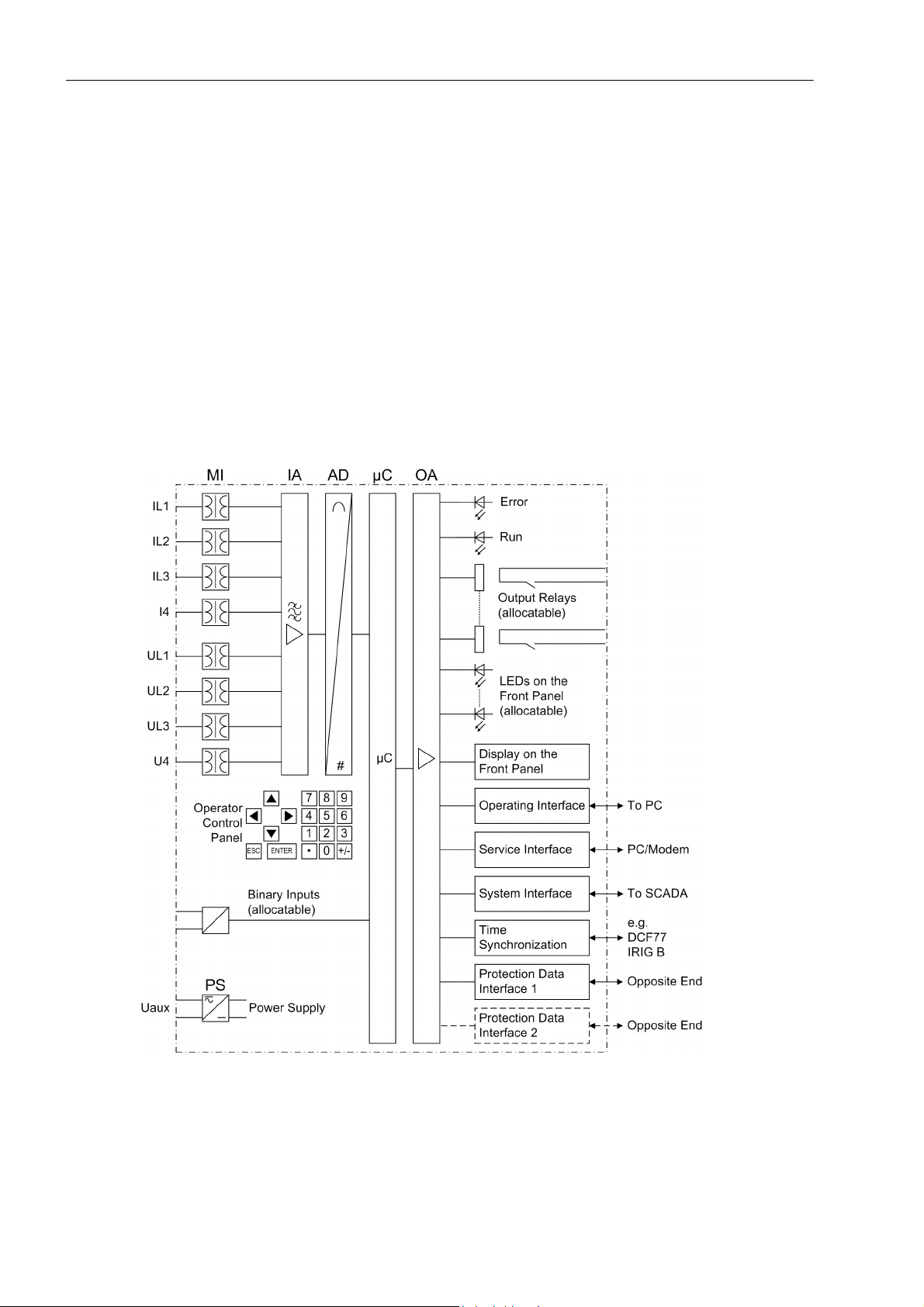
The SIPROTEC 4 7SD5 line protection is equipped with a powerful microprocessor system. This provides fully
digital processing of all functions in the device, from the acquisition of the measured values to the output of
commands to the circuit breakers, as well as the exchange of measured data with the other ends of the protected area. Figure 1-1 shows the basic structure of the device.
Analog inputs
The measuring inputs (MI) transform the currents and voltages from the instrument transformers and match
them to the internal signal levels for processing in the device. The device has 4 current and 4 voltage inputs.
Three current inputs are provided for the input of the phase currents, a further input (I
the earth current (current transformer starpoint or separate earth current transformer), the earth current of a
parallel line (for parallel line compensation) or the starpoint current of a source transformer (for earth fault direction determination, restricted earth fault protection).
) can be used to measure
4
22
Figure 1-1 Hardware structure of the line differential protection 7SD5
C53000-G1176-C169-5, Release date 02.2011
SIPROTEC, 7SD5, Manual
Page 23

One voltage input is provided for each phase-earth voltage. The connection of voltage transformers is not required for the differential protection, but for using the distance protection and other ancillary functions. A further
voltage input (U
nism and voltage check) or any other voltage U
to the IA input amplifier group.
The input amplifier group IA provides high-resistance termination for the input quantities. It contains filters that
are optimized with regard to bandwidth and processing speed.
The AD analog digital converter group contains analog/digital converters and memory chips for data transfer to
the microcomputer system.
Microcomputer system
Apart from processing the measured values, the microcomputer system µC also executes the actual protection
and control functions consisting of:
• Filtering and conditioning of the measured signals
• Continuous monitoring of the measured signals
• Monitoring of the pickup conditions of the individual protection functions
• Formation of the local differential protection values (phasor analysis and charge current computation) and
creation of the transmission protocol
• Decoding of the received transmission protocol, synchronisation of the differential protection values and
summing up of the differential currents and charge currents
• monitoring of the communication with the other devices of the line protection system
• Interrogation of threshold values and time sequences
• Processing of signals for the logic functions
• Decisions for trip and close commands
• Recording messages, fault data and fault values for analysis
• Operating system and related function management such as, e.g., data recording, real-time clock, communication, interfaces, etc.
Introduction
1.1 Overall Operation
) can optionally be used to measure the displacement voltage, a busbar voltage (for synchro-
4
(for overvoltage protection). The analog values are transferred
X
The information is provided via output amplifier OA.
Binary Inputs and Outputs
The microcomputer system obtains external information through binary inputs such as remote resetting or
blocking commands for protection functions. The computer system obtains the information from the system (e.g
remote resetting) or the external equipment (e.g. blocking commands). Outputs include, in particular, trip commands to circuit breakers and signals for remote annunciation of important events and conditions.
Front Elements
LEDs and an LC display provide information on the function of the device and indicate events, states and measured values.
Integrated control and numeric keys in conjunction with the LCD facilitate local communication with the device.
Thus, all information of the device, e.g. configuration and setting parameters, operating and fault messages,
and measured values can be retrieved or changed (see also chapter 2 and SIPROTEC 4 System Description).
Devices with control functions also allow control of switchgear from the front panel.
SIPROTEC, 7SD5, Manual
C53000-G1176-C169-5, Release date 02.2011
23
Page 24

Introduction
1.1 Overall Operation
Serial Interfaces
A personal computer running the DIGSI software can be connected to the serial operator interface (PC port)
on the front panel. This permits convenient operation of all functions of the device.
The serial service interface
suited for dedicated connection of the devices to the PC or for operation via a modem.
All device data can be transferred to a central master or main control system through the serial system
(SCADA) interface. This interface may be provided with various protocols and physical transmission modes to
suit the particular application.
A further port is provided for the time synchronisation
The operator or service interface allows the communication with the devices at all ends of the protected object
during commissioning, checking and also during operation using a standard browser via a communication
network This function is supported by a comprehensive „WEB Monitor“ which has been optimised especially
for the line protection system.
Protection data interfaces
The protection data interfaces are a particular case. Depending on the model, there are one or two protection
data interfaces available. Via these interfaces the measured value data of each end of the protected object is
transmitted to other ends; during this procedure measured values already received from another end may also
be added. Further information such as closing the local circuit breaker, pickup of the inrush restraint as well as
other external trip commands coupled via binary inputs or binary information can be transmitted to other ends
via the protection data interfaces.
Power Supply
These described functional units are supplied by a current supply PS with the necessary power in the different
voltage levels. Brief supply voltage dips which may occur on short circuits in the auxiliary voltage supply of the
devices are usually bridged by a capacitor (see also Technical Data, Chapter 4.1).
can also be used for communication with a PC using DIGSI. This is especially
of the internal clock via external synchronisation sources.
24
C53000-G1176-C169-5, Release date 02.2011
SIPROTEC, 7SD5, Manual
Page 25

1.2 Application Scope
The SIPROTEC 4 7SD5 line protection is a protection relay that combines differential and distance protection.
A multi-end fault locator allows to precisely locate faults in two-end lines, even in case of unfavourable operating or fault conditions.
The combined line protection is a selective short-circuit protection for overhead lines and cables with singleand multi-ended infeeds in radial, ring or any type of meshed systems of any voltage level. Measuring data are
compared separately for each phase. The network neutral can be earthed, compensated or isolated.
The device incorporates the functions which are normally required for the protection of an overhead line feeder
and is therefore capable of universal application. It may also be applied as time graded back-up protection to
all types of comparison protection schemes used on lines, transformers, generators, motors and busbars of all
voltage levels.
The inrush current restraint also allows the application of the 7SD5 even if a power transformer is situated
within the protected zone (ordering option) whose starpoint(s) might also be isolated, earthed or provided with
a Petersen coil.
A major advantage of the differential protection principle is the instantaneous tripping in the event of a shortcircuit at any point within the entire protected zone. The current transformers limit the protected zone at the
ends towards the remaining system. This rigid limit is the reason why the differential protection scheme shows
such an ideal selectivity.
Introduction
1.2 Application Scope
The line protection system requires a 7SD5 device as well as a set of current transformers at either end of the
protected zone.
Voltage transformers are required if protection functions requiring a voltage measurement (e.g. distance protection, fault locator) are used in addition to the differential protection. They are also needed for the acquisition
and display of measured values (voltages, power, power factor).
The devices located at the ends of the protected zone exchange measuring information via protection data interfaces using dedicated communication links (usually fibre optic cables) or a communication network, provided
that they operate with differential protection. The distance protection can exchange measuring information via
teleprotection functions with conventional connections (contacts), or transmit it through fast command channels
on the protection data interfaces (can be configured with DIGSI). Two type 7SD5 devices can be used for a
protected object with two ends: Cables, overhead line or both, even with transformer in the protected zone
(order variant). With type 7SD5 protected objects having 3 (three-terminal lines) or more ends can be protected
in addition to two-end lines, also with or without unit-connected transformer(s) (order variant). A maximum of 6
ends can be covered, which means that smaller busbar arrangements can also be protected. For each end a
7SD5*3 is used. If you set up a communication chain between more than two devices, 7SD5*2 can also be
used at the ends of the chain. For more information please refer to Section 2.2.1.
The protection data communication can be set up as a ring. This enables redundant operation in the event that
one communication line fails; the devices will automatically find the remaining healthy communication lines. But
even with two ends, the communication can be doubled to create redundancies.
Since fault-free data transmission is the prerequisite for the proper operation of the differential protection, it is
continuously monitored internally.
In the event of a communication failure, if there is no backup channel available, the devices can automatically
be switched to the second main protection function, i.e. distance protection, or to emergency operation using
an integrated time overcurrent protection, until communication is restored.
The communication can be used for transmitting further information. Apart from measured values, the transmission of binary commands or other information is also possible.
Alternatively the distance protection can be used as backup protection, just as the time overcurrent protection
can be used as backup time overcurrent protection, i.e. both operate independently and in parallel to the differential protection at each end.
SIPROTEC, 7SD5, Manual
C53000-G1176-C169-5, Release date 02.2011
25
Page 26

Introduction
1.2 Application Scope
Protection functions
Generally speaking, two basic functions are available in the 7SD5 line protection relay, namely differential and
distance protection. One of the protection functions can be configured at a time as the main protection function
(Main1). As an alternative, differential protection can be selected as the main protection function, and distance
protection as backup protection (Main2).
Recognition of short-circuits in the protection zone is the basic function of the differential protection. Also highresistance faults with small currents can be recognized. Even complex multiphase faults are precisely detected,
as the measured values are evaluated separately for each phase. The protection system is restrained against
inrush currents of power transformers. When switching onto a fault at any point of a line, an undelayed trip
signal can be emitted.
The basic function of the distance protection is the recognition of the fault distance by distance measurement.
In particular for complex multiphase faults, the distance measurement is of a multi-circuit design. Different
pickup schemes enable a good adaptation to system conditions and user philosophy. The system starpoint can
be isolated, compensated or earthed (with or without earth current limiting). Application is possible on long,
high-loaded lines with or without serial compensation. The distance protection may be supplemented by teleprotection using various signal transmission schemes (for fast tripping on 100 % of the line length). In addition,
an earth fault protection (for high-resistance earth faults, order variant) is available, which may be directional,
non-directional and additionally with signal transmission. On lines with weak or no infeed at one line end, it is
possible to achieve fast tripping at both line ends by means of the signal transmission schemes. When switching onto a fault at any point of a line, an undelayed trip signal can be emitted.
The integrated time overcurrent protection can be configured as a permanent backup protection at all line ends,
or as a protection for emergency operation. Emergency operation is a state in which the differential protection
cannot operate, for example because of a communication failure, and in which no parallel distance protection
is available (e.g. because of a measuring voltage failure). The time overcurrent protection has three definite
time overcurrent stages and one inverse time stage; a number of characteristics according to various standards
is available for the inverse time stage.
Depending on the order variant, the short-circuit protection functions can also trip single-pole. They may cooperate with an integrated automatic reclosure function (optionally) with which single-pole, three-pole or singleand three-pole automatic reclosure as well as multi-shot automatic reclosure are possible on overhead lines.
Before reclosure after three-pole tripping, the validity of the reclosure can be checked by voltage and/or synchronism check by the device (can be ordered optionally). It is possible to connect an external automatic reclosure function and/or synchronism check as well as double protection with one or two automatic reclosure functions.
In addition to the short-circuit protection functions mentioned, other protection functions are possible. A thermal
overload protection has been integrated which protects in particular cables and power transformers from undue
overheating due to overload. Other possible functions are multi-stage overvoltage, undervoltage and frequency
protection, circuit breaker failure protection and protection against the effects of power swings (simultaneously
active as power swing blocking for the distance protection) and earth fault differential protection (ordering option). To rapidly locate the damage to the line after a short-circuit, a multi-end fault locator is integrated which
also may compensate the influence of parallel lines, and of the fault resistance when power is flowing in the line.
Control Functions
The device is equipped with control functions which operate, close and open, switchgear devices via control
keys, the system interface, binary inputs and a PC with DIGSI software. The status of the primary equipment
can be transmitted to the device via auxiliary contacts connected to binary inputs. The present status (or position) of the primary equipment can be displayed on the device, and used for interlocking or plausibility monitoring. The number of the devices to be switched is limited by the binary inputs and outputs available in the device
or the binary inputs and outputs allocated for the switch position feedbacks. Depending on the mode of operation, one binary input (single point indication) or two binary inputs (double point indication) can be used. The
capability of switching primary equipment can be restricted by appropriate settings for the switching authority
(remote or local), and by the operating mode (interlocked/non-interlocked, with or without password validation).
26
C53000-G1176-C169-5, Release date 02.2011
SIPROTEC, 7SD5, Manual
Page 27

Interlocking conditions for switching (e.g. switchgear interlocking) can be established using the integrated userdefined logic.
Indications and measured values; fault recording
The operational indications provide information about conditions in the power system and the device. Measurement quantities and values that are calculated can be displayed locally and communicated via the serial interfaces.
Device messages can be assigned to a number of LEDs on the front panel (programmable), can be externally
processed via output contacts (programmable), linked with user-definable logic functions and/or issued via
serial interfaces (see Communication below).
During a fault (system fault) important events and changes in conditions are saved in fault logs. Instantaneous
fault values are also saved in the device and may be analysed at a later time.
As a special feature the values are synchronized between the line terminals via the communication link.
Communication
Serial interfaces are available for the communication with operating, control and memory systems.
A 9-pin DSUB socket on the front panel is used for local communication with a personal computer. By means
of the SIPROTEC 4 operating software DIGSI, all operational and evaluation tasks can be executed via this
operator
interface, such as specifying and modifying configuration parameters and settings, configuring userspecific logic functions, retrieving operational and fault messages and measured values, reading out and displaying fault recordings, inquiring device conditions and measured values, issuing control commands.
Introduction
1.2 Application Scope
To establish an extensive communication with other digital operating, control and memory components the
device may be provided with further interfaces depending on the order variant.
The service interface
can be operated via the RS232 or RS485 interface and also allows communication via
modem. For this reason, remote operation is possible via PC and the DIGSI operating software, e.g. to operate
several devices via a central PC.
The system
interface is used for central communication between the device and a control center. It can be operated through the RS232, the RS485 or the FO port. Several standardized protocols are available for data
transmission. An EN 100 module allows integrating the devices into 100 MBit Ethernet communication networks of the process control and automation system, using IEC 61850 protocols. In parallel to the link with the
process control and automation system, this interface can also handle DIGSI communication and inter-relay
communication using GOOSE messaging.
Another interface is provided for the time synchronization
of the internal clock via external synchronization
sources (IRIG-B or DCF77).
Other interfaces provide for communication between the devices at the ends of the protected object. These
protection data interfaces
have been mentioned above in the protection functions.
The operator or service interface allows to operate the device remotely or locally using a standard browser. This
is possible during commissioning, checking and also during operation with the devices at all ends of the protected object via a communication network. For this purpose, a „WEB Monitor“ is provided, which has been
optimised specially for the differential protection system, but which has also been upgraded to meet the distance protection requirements.
SIPROTEC, 7SD5, Manual
C53000-G1176-C169-5, Release date 02.2011
27
Page 28

Introduction
1.3 Characteristics
1.3 Characteristics
General Features
• Powerful 32-bit microprocessor system
• Complete digital processing of measured values and control, from the digitzing of the analog input values,
the processing and organization of the communication between devices up to the closing and tripping commands to the circuit breakers
• Complete galvanic separation and interference immunity of the internal processing circuits from the measurement, control, and power supply circuits by analog input transducers, binary inputs and outputs and the
DC/DC or AC/DC converters
• Suited for lines with up to 6 ends, even with transformers in the protected zone (order option)
• Simple device operation using the integrated operator panel or a connected personal computer with operator
guidance
• Storage of fault indications and instantaneous values for fault recording
Differential protection
• Differential protection for up to 6 ends with digital protection data transmission
• Protection for all types of short-circuits in systems with any neutral-point treatment conditioning
• Reliable differentiation between load and fault conditions also in high-resistant, current-weak faults by adaptive measuring procedures
• High sensitivity in case of weakly loaded system, extreme stability against load jumps and power swings
• Phase-selective measurement ensures that the pickup sensitivity is independent of the fault type
• Suited for transformers in the protected zone (order variant)
• Detection of high-resistance, weak-current faults due to high sensitivity of the protection functions
• Insensitive to inrush and charging currents – also for transformers in the protected zone – and to higherfrequency transient processes
• Charging current compensation; therefore increased pickup sensitivity
• High stability also for different current transformer saturation
• Adaptive stabilisation that is automatically derived from the measured quantities and the configured current
transformer data
• Fast, phase segregated tripping also on weak or zero infeed ends (breaker intertrip)
• Low dependence on frequency
• Digital protection data transmission; communication between devices via dedicated communication links (in
general optical fibre) or a communication system
28
• Communication possible via a single copper wire pair (typically 8 km, max. up to 30 km, depending on cable
type used)
• Synchronization via GPS possible, resulting in automatic correction of transmission time differences thus
increasing once more the sensitivity
• Permanent monitoring of the protection data transmission concerning disturbance, failure or transfer time
deviations in the transmission network with automatic transfer time correction
• Automatic changeover of the communication paths possible in case of transmission failure or transmission
disturbance
C53000-G1176-C169-5, Release date 02.2011
SIPROTEC, 7SD5, Manual
Page 29

• Phase segregated tripping possible (for operation with single-pole or single-and three-pole auto-reclosure)
(order variant)
Distance Protection (optional)
• Can be used either to operate in parallel to differential protection, or as the main protection function
• Protection for all types of faults in systems with earthed, compensated or isolated starpoint
• Selectable polygonal tripping characteristic or MHO characteristic
• Possibility to choose between Z pickup, I>-, U/I- or U/I/ϕ pickup, enabling the adaptation to different system
conditions and the user philosophies
• Reliable differentiation between load and fault conditions also on long, high-load lines
• High sensitivity in the case of a lightly loaded system, extreme stability against load jumps and power swings
• Optimum adaptation to the line parameters by means of the tripping characteristic with diverse configuration
parameters and „load trapezoid“ (elimination of the possible load impedances)
• Six measuring systems for each distance zone
• Six distance zones, selectable in forward or reverse direction or non-directional, one can be graded as an
overreach zone
Introduction
1.3 Characteristics
• Nine time stages for the distance zones
• Direction determination (with polygon) or polarization (with MHO characteristic) is done with unfaulted loop
voltages and voltage memory, thereby achieving unlimited directional sensitivity not affected by capacitive
voltage transformer transients
• Suitable for lines with serial compensation
• Insensitive to current transformer saturation
• Compensation of the influence of parallel line is possible
• Shortest command time significantly less than one cycle
• Phase-selective tripping (in conjunction with single-pole or single- and three-pole auto-reclosure) possible
• Instantaneous tripping following switching onto a fault is possible
• Two setting pairs for earth impedance compensation
Power Swing Supplement (optional)
• Power swing detection with dZ/dt measurement from three measuring systems
• Power swing detection up to 10 Hz swing frequency
• Remains in service also during single-pole dead times
• settable power swing programs
• prevention of undesired tripping by the distance protection during power swings
• Tripping for out-of-step conditions can be configured
SIPROTEC, 7SD5, Manual
C53000-G1176-C169-5, Release date 02.2011
29
Page 30

Introduction
1.3 Characteristics
Teleprotection Supplement (optional)
• Different schemes which may be set:
• Transfer trip (direct, via pickup or a separately settable overreach zone)
• Comparison schemes (permissible overreach transfer trip = POTT or blocking schemes with separate overreach zone or directional pickup)
• Pilot wire comparison/reverse interlocking (with direct current for local connections or extremely short lines)
• suitable for lines with two or three ends
• Phase segregated transmission possible in lines with two ends
• Signal exchange between the devices via binary outputs and binary inputs, either directly via the device contacts or via the protection data interface(s)
Earth Fault Protection (optional)
• Time overcurrent protection with a maximum of three definite time stages (DT) and one inverse time stage
(IDMT) for high resistance earth faults in earthed systems
• For inverse-time overcurrent protection a selection from various characteristics based on several standards
is possible
• The inverse time stage can also be set as fourth definite time stage
• High sensitivity (from 3 mA on, depending on the version)
• Phase current restraint against error currents during current transformer saturation
• Second harmonic inrush restraint
• Optional earth fault protection with voltage-dependent tripping time or with zero sequence power inverse
time tripping
• Each stage can be set to be non-directional or directional in forward or reverse direction
• Single-pole tripping enabled by integrated phase selector
• Direction determination with automatic selection of the larger of zero sequence voltage or negative sequence voltage (U
, IY or U2), with zero sequence system quantities (I0, U0), with zero sequence current and
0
transformer starpoint current (I
power (3I
· 3U0)
0
• One or more stages may function in conjunction with a teleprotection scheme; also suited for lines with three
ends
• Instantaneous tripping by any stage when switching onto a fault
Sensitive Earth Fault Detection (optional)
• for compensated or isolated networks
• Detection of the displacement voltage
, IY), with negative sequence system quantities (I2, U2) or with zero sequence
0
30
• Determination of grounded phase
• Sensitive earth fault directional determination
• Angle error correction for current transformers
C53000-G1176-C169-5, Release date 02.2011
SIPROTEC, 7SD5, Manual
Page 31

Restricted earth fault protection
• Earth fault protection for earthed transformer windings
• Short tripping time
• High sensitivity for earth faults
• High stability against external earth faults using the magnitude and phase relationship of through-flowing
earth current
Tripping at Li ne Ends with no or Weak Infeed (optional)
• Possible in conjunction with teleprotection schemes
• Allows fast tripping at both line ends, even if there is no or only weak infeed available at one line end
• Phase segregated tripping and single-pole automatic reclosure is possible (version with single-phase tripping)
External Direct and Remote Tripping
• Tripping at the local line end from an external device via a binary input
• Tripping of the remote line end by internal protection functions or an external device via a binary input (with
teleprotection)
Introduction
1.3 Characteristics
Transm ission of information
• Transmission of the measured values from all ends of the protected object with the magnitude and phase
• Transmission of up to 4 fast commands to all remote ends (order option)
• Transmission of up to 24 additional binary signals to all remote ends (order option)
Time Overcurrent Protection
• Selectable as emergency function during a failure of the main protection function(s) due to a failure of the
data communication and/or the measuring voltages, or as backup function
• Maximally three definite time stages (DT) and one inverse time stage (IDMT), each for phase currents and
for earth currents
• For inverse-time overcurrent protection a selection from various characteristics based on several standards
is possible
• Blocking capability e.g. for reverse interlocking with any stage;
• Instantaneous tripping by any stage when switching onto a fault
• End fault protection: fast tripping on faults between the current transformer and line isolator (when the isolator switching status feed back is available); particularly well suited to substations with
arrangements
High Current Switch-onto-Fault Protection
1
/2 circuit breaker
• Fast tripping for all faults on 100 % line length
• Selectable for manual closure or following each closure of the circuit breaker
• With integrated line energization detection.
SIPROTEC, 7SD5, Manual
C53000-G1176-C169-5, Release date 02.2011
31
Page 32

Introduction
1.3 Characteristics
Automatic Reclosure (optional)
• For reclosure after single-pole, three-pole or single-pole and three-pole tripping
• Single or multiple reclosure (up to 8 reclosure attempts)
• With separate action times for every reclosure attempt, optionally without action times
• With separate dead times after single-pole and three-pole tripping, separate for the first four reclosure attempts
• With the option of an adaptive dead time: in this case only one device controls the automatic reclosure
cycles whilst at the other end(s) the automatic reclosure solely depends on the one controlling device. The
criteria used are voltage measurement and/or the transmitted CLOSE command (Remote-CLOSE)
• Controlled optionally by protection pickup with separate dead times after single-, two- or three-pole starting
Synchronism and Voltage Check (optional)
• Verification of the synchronous conditions before reclosing after three-pole tripping
• Fast measuring of voltage difference U
• Alternatively, check of the de-energized state before reclosing
• Closing at asynchronous system conditions with prediction of the synchronization time
• Settable minimum and maximum voltage
• Verification of the synchronous conditions or de-energized state also possible before the manual closing of
the circuit breaker, with separate limit values
• Also measurement via transformer
• Measuring voltages optionally phase-phase or phase-earth
Voltage Protection (optional)
• Two overvoltage stages for the phase-earth voltages
• Two overvoltage stages for the phase-phase voltages
• Two overvoltage stages for the positive sequence voltage, optionally with compounding
• Two overvoltage stages for the negative sequence voltage
• Two overvoltage stages for the zero sequence voltage or any other single-phase voltage
• Settable dropout to pickup ratios for the overvoltage protection functions
• Two undervoltage stages for the phase-earth voltages
, of the phase angle difference ϕ
diff
and frequency difference f
diff
diff
• Two undervoltage stages for the phase-phase voltages
• Two undervoltage stages for the positiv sequence voltage
• Settable current criterion for undervoltage protection functions
Frequency Protection (optional)
• Monitoring for underfrequency (f<) and/or overfrequency (f>) with 4 frequency limits and delay times that are
independently adjustable
• Particularly insensitive to harmonics and abrupt phase angle changes
• Large frequency range (approx. 25 Hz to 70 Hz)
32
C53000-G1176-C169-5, Release date 02.2011
SIPROTEC, 7SD5, Manual
Page 33

Fault Location
• Optionally single-ended (conventional) or double-ended fault location via communication interfaces;
• Initiated by trip command or reset of the fault detection
• Fault location output in Ohm, kilometers or miles and % of line length
• Output of the fault location also possible in BCD code
• Parallel line compensation can be selected
• Taking into consideration the load current in case of single-phase earth faults fed from both sides (configurable)
• Possibility to take into account line asymmetry and different line sections
Circuit Breaker Failure Protection
• With definite time current stages for monitoring the current flow through every pole of the circuit breaker
• Separate pickup thresholds for phase and earth currents
• Independent timers for single-pole and three-pole tripping;
• Start by trip command of every internal protection function
Introduction
1.3 Characteristics
• Start by external trip functions possible
• Single-stage or two-stage
• Short dropout and overshoot times
• End fault protection and pole discrepancy monitoring possible
Thermal Overload Protection
• Provides thermal replica of the current heat losses of the protected object
• R.m.s. measurement of all three phase currents
• Adjustable thermal and current-dependent warning stages
User-defined Logic Functions (CFC)
• Freely programmable combination of internal and external signals for the implementation of user-defined
logic functions
• All typical logic functions
• Time delays and limit value inquiries
Commissioning, Operation, Maintenance
• Display of magnitude and phase angle of local and remote measured values
• Indication of the calculated differential and restraint currents
• Display of the measured values of the communication link, such as transmission delay and availability
• Function logout of a device from the line protection system possible during maintenance work at an end of
a power line, test mode and commissioning mode
SIPROTEC, 7SD5, Manual
C53000-G1176-C169-5, Release date 02.2011
33
Page 34

Introduction
1.3 Characteristics
Command Processing
• Switchgear can be switched on and off manually via local control keys, the programmable function keys on
the front panel, via the system interface (e.g. by SICAM or LSA), or via the operator interface (using a personal computer and the operating software DIGSI)
• Feedback on switching states via the circuit breaker auxiliary contacts (for commands with feedback)
• Monitoring of the circuit breaker position and of the interlocking conditions for switching operations.
Monitoring Functions
• Increase of the availability of the device by monitoring of the internal measurement circuits, auxiliary power
supply, hardware, and software
• Current transformer and voltage transformer secondary circuits are monitored using summation and symmetry check techniques
• Monitoring of communication with statistics showing the number of faulty transmission telegrams
• Check of the consistency of protection settings at all line ends: blocking of the differential protection system
in case of inconsistent settings which could lead to a malfunction
• Trip circuit supervision possible
• Check of local and remote measured values and comparison of both
• Broken wire supervision for the secondary CT circuits with fast phase segregated blocking of the line protection system in order to avoid malfunction
• Supervision of measuring voltage failure using "Fuse Failure Monitor"
Additional Functions
• Battery buffered real-time clock, which may be synchronized via a synchronization signal (e.g. DCF77, IRIG
B, GPS via satellite receiver), binary input or system interface
• Automatic time synchronization between the devices at the ends of the protected object via the protection
data transmission
• Continuous calculation and display of operational measured values on the front of the device. Display of
measured values of the remote end or of all ends
• Indication memory for the last 8 network faults (faults in the power system), with real time stamps (1 ms resolution)
• Fault recording and transmission of the data for fault recording for a maximum time range of approximately
30 s, synchronised between the devices of a line protection system
• Switching statistics: Counting of the trip and close commands issued by the device, as well as recording of
the fault current data and accumulation of the interrupted fault currents
• Communication with central control and memory components possible via serial interfaces (depending on
order variant), optionally via RS232, RS485, modem or fibre-optic cable
34
• Commissioning aids such as connection and direction checks and circuit breaker test functions
• Comprehensive support when checking and commissioning from PC or laptop by means of „WEB Monitor“:
The communication topology of the line protection and communication system, phasor diagrams of all currents and (if applicable) voltages at all ends of the line protection system, as well as the differential protection
and distance protection characteristics, are graphically displayed on the screen
■
C53000-G1176-C169-5, Release date 02.2011
SIPROTEC, 7SD5, Manual
Page 35

Functions 2
This chapter describes the individual functions of the SIPROTEC 4 device 7SD5. It shows the setting possibilities for each function in maximum configuration. Guidelines for establishing setting values and, where required,
formulae are given.
Based on the following information, it can also be determined which of the provided functions should be used.
2.1 General 37
2.2 Protection Data Interfaces and Protection Data Topology 74
2.3 Differential Protection 93
2.4 Breaker Intertrip and Remote Tripping 110
2.5 Distance Protection 115
2.6 Power Swing Detection (optional) 181
2.7 Teleprotection for Distance Protection (optional) 187
2.8 Earth Fault Protection in Earthed Systems (optional) 217
2.9 Teleprotection for Earth Fault Protection (optional) 249
2.10 Restricted Earth Fault Protection (optional) 265
2.11 Measures for Weak and Zero Infeed 273
2.12 Direct Local Trip 285
2.13 Transmission of Binary Commands and Messages 287
2.14 Instantaneous High-Current Switch-onto-Fault Protection (SOTF) 290
2.15 Sensitive Earth Flt.(comp/ isol. starp.) 295
2.16 Backup Time Overcurrent Protection 302
2.17 Automatic Reclosure Function (optional) 318
2.18 Synchronism and Voltage Check (optional) 348
2.19 Undervoltage and Overvoltage Protection (optional) 361
2.20 Frequency Protection (optional) 381
2.21 Fault Locator 387
2.22 Circuit Breaker Failure Protection 396
2.23 Thermal Overload Protection 414
2.24 Monitoring Functions 418
2.25 Function Control and Circuit Breaker Test 443
SIPROTEC, 7SD5, Manual
C53000-G1176-C169-5, Release date 02.2011
35
Page 36

Functions
2
2.26 Additional Functions 464
2.27 Command Processing 486
36
C53000-G1176-C169-5, Release date 02.2011
SIPROTEC, 7SD5, Manual
Page 37

2.1 General
A few seconds after the device is switched on, the default display appears on the LCD. Depending on the
device version either measured values (four-line display) or a single-phase switching diagram of the feeder
status (graphic display) is displayed in the 7SD5.
Configuration settings can be entered by using a PC and the DIGSI operating software and transferred via the
operator interface on the front panel of the device or via the service interface. The procedure is described in
detail in the SIPROTEC 4 System Description. Entry of password no. 7 (parameter set) is required to modify
configuration settings. Without the password, the settings may be read, but may not be modified and transmitted to the device.
The function parameters, i.e. function options, threshold values, etc., can be changed via the front panel of the
device, or via the operator or service interface from a personal computer using DIGSI. The level 5 password
(individual parameters) is required.
This general section describes which device settings reflect the interaction between your substation, its measuring points (current and voltage transformers), the analog device connections and the various protection
functions of the device.
First (Subsection 2.1.1) you have to specify which protection functions you want to use since not all functions
integrated in the device are necessary, useful or even possible for your relevant application.
Functions
2.1 General
After entering some System Data (frequency), you inform the device (Section 2.1.2) of the properties of the
main protected object. This comprises e.g. nominal system data, nominal data of instrument transformers, polarity and connection type of measured values
The above information is sufficient to describe the protected object to the device's main protection function, i.e.
the differential protection. For the other protection functions (e.g. backup distance protection) you select what
measured values will be processed and in which way.
You will be informed how to set the circuit breaker data, and find out about setting groups and how to use them.
Last but not least, you can set general data which are not dependent on any protection functions.
2.1.1 Functional Scope
2.1.1.1 Configuration of the Scope of Functions
The 7SD5 device contains a series of protection and additional functions. The hardware and firmware is designed for this scope of functions. Additionally, the command functions can be matched to the system conditions. Furthermore, individual functions may be enabled or disabled during configuration, or interaction
between functions may be adjusted.
Example
A substation has feeders with overhead lines and transformers. Fault location is to be performed on the overhead lines only. In the devices for the transformer feeders this function is therefore set to „Disabled“.
for the configuration of scope of functions:
The available protection functions and additional functions can be configured as Enabled or Disabled. For
some functions, a choice between several options is possible which are described below.
Functions configured as Disabled are not processed by the 7SD5. There are no indications, and corresponding settings (functions, limit values) are not displayed during setting.
SIPROTEC, 7SD5, Manual
C53000-G1176-C169-5, Release date 02.2011
37
Page 38

Functions
2.1 General
Note
The functions and default settings available depend on the device version ordered.
2.1.1.2 Control of the Main Protection Functions
Differential and Distance Protection
If the order option specifies that the 7SD5 universal line protection includes the distance protection, the device
can be operated in three modes:
1. Differential protection with distance protection
2. Differential protection only
3. Distance protection only
In mode 1, the distance protection operates in parallel with the differential protection. In this mode, both protection functions are configured (address 112 DIFF.PROTECTION; address 115 Phase Distance, address
116 Earth Distance and address 117 Dis. PICKUP), and can be switched ON or OFF with the addresses
1201 STATE OF DIFF. and 1501 FCT Distance. When the differential protection is switched off or blocked,
the distance protection continues to operate without restrictions.
You can also operate the differential protection without distance protection (mode 2, addresses 115, 116 and
117 = Disabled). The device behaves in this case like a normal line differential protection relay.
In mode 3 the differential protection is not configured (address 112 DIFF.PROTECTION = Disabled), the dis-
tance protection operates as main protection (provided that it is activated).
2.1.1.3 Setting Notes
Configuring the functional scope
The scope of functions with the available options is set in the Functional Scope dialog box to match plant requirements.
Most settings are self-explanatory. The special cases
Special features
If use of the setting group changeover function is desired, address 103 Grp Chge OPTION should be set to
Enabled. In this case, up to four different groups of settings may be changed quickly and easily during device
operation (see also Section 2.1.3). With the setting Disabled only one parameter group is available.
Address 110 Trip mode is only valid for devices that can trip single-pole or three-pole. Set 1-/3pole to
enable also single-pole tripping, i.e. if you want to utilise single-pole or single-pole/three-pole automatic reclosure. This requires that an internal automatic reclosure function exists or that an external reclosing device is
used. Furthermore, the circuit breaker must be capable of single-pole tripping.
are described below:
38
Note
If you have changed address 110, save your changes first via OK and reopen the dialog box since the other
setting options depend on the selection in address 110.
C53000-G1176-C169-5, Release date 02.2011
SIPROTEC, 7SD5, Manual
Page 39

Differential protection
The differential protection and the distance protection can each be configured as the main protection function.
If the differential protection is the main protection function of the device, DIFF.PROTECTION (address 112) is
set to Enabled. This also implies the supplementary functions of the differential protection such as breaker
intertrip.
For the communication of the protection signals to one or more device(s) each device is equipped with one or
two protection data interfaces (order option). The assignment of the protection data interfaces is essential for
the line protection system, i.e., the interaction of the devices at the ends of the protected object. Enable protection data interface 1 P. INTERFACE 1 in address 145, and protection data interface 2 (if available) P.
INTERFACE 2 in address 146, if you want to use them. At least one protection data interface is required to
use the differential protection function. A protected object with two ends requires at least one protection data
interface in each device. If there are more ends, it must be guaranteed that all devices that belong together are
interconnected directly or indirectly (via other devices). Section 2.2.1 Protection Data Topology provides more
information.
The number of devices (address 147 NUMBER OF RELAY) must match the number of the measuring points at
the borders of the object to be protected. Please observe that only current transformer sets that limit the protected object are counted. The line in Figure 2-1, for instance, has three measuring points and thus three
devices because it is limited by three current transformer sets. Two devices would normally be sufficient if
current transformers 1 and 2 are connected in parallel at the secondary side and connected to a device. However, in the event of an external fault causing a high short-circuit current to pass through the current transformers 1 and 2, the restraint of the differential protection would be insufficient.
Functions
2.1 General
Figure 2-1 Protected object with 3 ends and 3 devices
If the device is connected to voltage transformers, this condition has to be set in address 144 V-
TRANSFORMER. The voltage dependent functions such as distance protection can only be used if voltage transformers are connected.
If a power transformer is located in the protected zone, set this condition in address 143 TRANSFORMER (or-
dering option). The actual transformer data will be requested when the general protection data are set (see
Section 2.1.4.1 under margin heading „Topological Data for Transformers“ (optional)).
If you want to configure differential protection with charging current compensation, set this condition in address
149 charge I comp..
SIPROTEC, 7SD5, Manual
C53000-G1176-C169-5, Release date 02.2011
39
Page 40

Functions
2.1 General
Distance protection
Depending on the version ordered, the distance protection of the 7SD5, if configured as the main protection
function or in combination with differential protection, features a range of pickup modes, from which the type
best suited for the particular system conditions can be selected. If according to the ordering code the device is
equipped with impedance pickup only (7SD5***-*****-*E** and 7SD5***-*****-*H***), you can select the tripping
characteristic to be used by the distance protection. To do so, select address 115 for the phase-to-phase measuring units Phase Distance and address 116 for the phase-to-earth measuring units Earth Distance.
You can select between the polygonal tripping characteristic Quadrilateral and the MHO characteristic
MHO. The sections 2.5.2 and 2.5.3 provide a detailed overview of the characteristics and measurement methods. The two adresses can be set seperately and differently. If the device is to be used only for phase-to-earth
loops or only for phase-to-phase loops, set the function that is not required to Disabled.
Other pickup procedures are available with the ordering variants 7SD5***-*****-*D**, 7SD5***-*****-*G**,
7SD5***-*****-*K**, and 7SD5***-*****-*M**. The properties of these procedures are described in detail in
Section 2.5.1.
If the fault current magnitude alone is a reliable criterion for distinction between a fault occurrence and load
operation (incl. tolerable overload), set Address 117 Dis. PICKUP = I> (overcurr.) (overcurrent pickup).
If the voltage drop is required as another pickup criterion, select the setting U/I (voltage-dependent current
pickup). For heavily loaded high-voltage lines and extra-high-voltage lines, the setting U/I/ϕ (voltage and
phase-angle dependent current pickup) may be required. With the setting Z< (quadrilat.) (... pickup) the
distance zones which are set highest establish the pickup criteria. If you set address 117 Dis. PICKUP to
Disabled, the distance protection function and all associated functions will not be available.
If a pickup of zone Z1 of the distance protection shall be possible only after exceeding an additional currentthreshold value, set the parameter 119 Iph>(Z1) to Enabled. Select the setting Disabled if the additional
threshold value is not required.
Please note that the power swing supplement (see also Section 2.6) only works together with the Z<
(quadrilat.) pickup. In all other cases it is ineffective, even though you have set address 120 Power
Swing = Enabled
.
To complement the distance protection function by teleprotection schemes, you can select the desired scheme
at address 121 Teleprot. Dist.. You can select the permissive underreach transfer trip with pickup PUTT
(Pickup) and with overreach zone PUTT (Z1B), the teleprotection scheme POTT, directional comparison
pickup Dir.Comp.Pickup, unblocking with Z1B UNBLOCKING, blocking scheme BLOCKING, and the
schemes with pilot wire comparison Pilot wire comp and Rev. Interlock (reverse interlocking). If you
do not want to use teleprotection in conjunction with distance protection set Disabled.
The Direct Local Trip (address 122 DTT Direct Trip) is a command that is initiated from an external device
for tripping the local circuit breaker.
With address 125 Weak Infeed you can select a supplement to the teleprotection schemes. Set Enabled to
apply the classical scheme for echo and weak infeed tripping. The setting Logic no. 2 switches this function
to the French specification. This setting is available in the device variants for the region France (only version
7SD5***-**D** or 10th digit of order number = D).
At address 126 Back-Up O/C you can set the characteristic group which the time overcurrent protection uses
for operation. In addition to the definite time overcurrent protection, an inverse time overcurrent protection can
be configured depending on the version ordered that operates either according to an IEC characteristic (TOC
IEC) or according to an ANSI characteristic (TOC ANSI). The different characteristics are depicted in the Technical Data. You can also disable the time overcurrent protection (Disabled).
40
C53000-G1176-C169-5, Release date 02.2011
SIPROTEC, 7SD5, Manual
Page 41

Functions
2.1 General
At address 131 Earth Fault O/C you can set the characteristic group which the earth fault protection uses
for operation. In addition to the definite time overcurrent protection, which covers up to three phases, an
inverse-time earth fault protection function may be configured depending on the version ordered that operates
either according to an IEC characteristic (TOC IEC) or an ANSI characteristic (TOC ANSI) or according to a
logarithmic-inverse characteristic (TOC Logarithm.). If an inverse-time characteristic is not required, the
stage usually designated „inverse time“ can be used as the fourth definite-time stage (Definite Time). Alternatively, you can select an earth fault protection with inverse-time characteristic U0 inverse or a zero sequence power protection Sr inverse. The different characteristics are depicted in the Technical Data. You
can also disable the earth fault protection (Disabled).
When using the earth fault protection, it can be complemented by teleprotection schemes. Select the desired
scheme at address 132 Teleprot. E/F. You can select the direction comparison scheme
Dir.Comp.Pickup, the unblocking scheme UNBLOCKING and the blocking scheme BLOCKING. The procedures are described in detail in Section 2.9. If you do not want to use teleprotection in conjunction with earth
fault protection set Disabled.
If the device features an automatic reclosing function, address 133 and 134 are of importance. Automatic reclosure is only permitted for overhead lines. It must not be used in any other case. If the protected object consists of a combination of overhead lines and other equipment (e.g. overhead line in unit with a transformer or
overhead line/cable), reclosure is only permissible if it can be ensured that it can only take place in the event
of a fault on the overhead line. If no automatic reclosing function is desired for the feeder at which 7SD5 operates, or if an external device is used for reclosure, set address 133 Auto Reclose to Disabled.
Otherwise set the number of desired reclosing attempts there. You can select 1 AR-cycle to 8 AR-cycles.
You can also set ADT (adaptive dead times); in this case the behaviour of the automatic reclosure function is
determined by the cycles of the remote end. The number of cycles must however be configured at least in one
of the line ends which must have a reliable infeed. The other end — or other ends, if there are more than two
line ends — may operate with adaptive dead time. Section 2.17 provides detailed information on this topic.
The AR control mode at address 134 allows a total of four options. On the one hand, it can be determined
whether the auto reclose cycles are carried out according to the fault type detected by the pickup of the starting
protection function(s) (only for three-pole tripping) or according to the type of trip command. On the other
hand, the automatic reclosure function can be operated with or without action time.
The setting Trip with T-action / Trip without T-action ... (default setting = Trip with T-action
... ) is preferred if single-pole
or single-pole/three-pole auto reclose cycles are provided for and possible. In this
case, different dead times (for every AR cycle) are possible after single-pole tripping and after three-pole tripping. The tripping protection function determines the type of tripping: Single-pole or three-pole. The dead time
is controlled in dependence on this.
The setting Pickup with T-action / Pickup without T-action ... ... (Pickup with T-action ...)
is only possible and visible if only three-pole tripping is desired. This is the case when either the ordering
number of the device model indicates that it is only suited for three-pole tripping, or when only three-pole tripping is configured (address 110 Trip mode = 3pole only, see above). In this case, different dead times
can be set for the auto reclose cycles following 1
-, 2- and 3-phase faults. The decisive factor here is the pickup
situation of the protection functions at the instant the trip command disappears. This operating mode enables
making the dead times dependent on the type of fault also for three-pole reclosure cycles. Tripping is always
three-pole.
The setting Trip with T-action with action time) provides an action time for each auto-reclose cycle. The
action time is started by a general pickup of all protection functions. If there is no trip command yet when the
action time has expired, the corresponding automatic reclosure cycle cannot be executed. Section 2.17 provides detailed information on this topic. This setting is recommended for time-graded protection. If the protection function which is to operate with automatic reclosure, does not have a general pickup signal for starting the
action times, select Trip without T-action... (without action time).
SIPROTEC, 7SD5, Manual
C53000-G1176-C169-5, Release date 02.2011
41
Page 42

Functions
2.1 General
Address 137 U/O VOLTAGE allows activating the voltage protection function with a variety of undervoltage and
overvoltage protection stages. In particular, the overvoltage protection with the positive sequence system of the
measuring voltages provides the option to calculate the voltage at the other, remote line end via integrated compounding. This is particularly useful for long transmission lines where no-load or low-load conditions prevail and
an overvoltage at the other line end (Ferranti effect) is to cause tripping of the local circuit breaker. In this case
set address 137 U/O VOLTAGE to Enabl. w. comp. (enabled with compounding). Do not use compounding
on lines with series capacitors!
For the fault location, besides Enabled and Disabled, you can also determine in address 138 Fault
Locator that the fault distance is output in BCD code (4-bit units, 4-bit tens and 1-bit hundreds, as well as 1bit „data valid“) via binary outputs (with BCD-output). A corresponding number of output relays (No. 1143
through 1152 in the configuration matrix) must be made available and routed for this purpose. For doubleended fault location, address 3807 two ended must be set to ON. Please note that address 160 L-sections
FL is used for the specification of the number of sections into which your line length is divided (e.g. cable overhead line).
For the trip circuit supervision set at address 140 Trip Cir. Sup. the number of trip circuits to be monitored:
1 trip circuit, 2 trip circuits or 3 trip circuits, unless you omit it (Disabled).
2.1.1.4 Settings
Addr. Parameter Setting Options Default Setting Comments
103 Grp Chge OPTION Disabled
Disabled Setting Group Change Option
Enabled
110 Trip mode 3pole only
3pole only Trip mode
1-/3pole
112 DIFF.PROTECTION Enabled
Enabled Differential protection
Disabled
115 Phase Distance Quadrilateral
Quadrilateral Phase Distance
MHO
Disabled
116 Earth Distance Quadrilateral
Quadrilateral Earth Distance
MHO
Disabled
117 Dis. PICKUP Z< (quadrilat.)
I> (overcurr.)
Z< (quadrilat.) Distance protection pickup
program
U/I
U/I/ϕ
Disabled
119 Iph>(Z1) Disabled
Disabled Additional Threshold Iph>(Z1)
Enabled
120 Power Swing Disabled
Disabled Power Swing detection
Enabled
121 Teleprot. Dist. PUTT (Z1B)
Disabled Teleprotection for Distance prot.
PUTT (Pickup)
POTT
Dir.Comp.Pickup
UNBLOCKING
BLOCKING
Rev. Interlock
Pilot wire comp
Disabled
122 DTT Direct Trip Disabled
Disabled DTT Direct Transfer Trip
Enabled
42
C53000-G1176-C169-5, Release date 02.2011
SIPROTEC, 7SD5, Manual
Page 43

Addr. Parameter Setting Options Default Setting Comments
124 HS/SOTF-O/C Disabled
Enabled
125 Weak Infeed Disabled
Disabled Instantaneous HighSpeed/SOTF
Overcurrent
Disabled Weak Infeed (Trip and/or Echo)
Enabled
Logic no. 2
126 Back-Up O/C Disabled
TOC IEC Backup overcurrent
TOC IEC
TOC ANSI
130 Sens. Earth Flt Disabled
Enabled
131 Earth Fault O/C Disabled
Disabled Sensitive Earth Flt.(comp/ isol.
starp.)
Disabled Earth fault overcurrent
TOC IEC
TOC ANSI
TOC Logarithm.
Definite Time
U0 inverse
Sr inverse
132 Teleprot. E/F Dir.Comp.Pickup
UNBLOCKING
Disabled Teleprotection for Earth fault over-
curr.
BLOCKING
Disabled
133 Auto Reclose 1 AR-cycle
Disabled Auto-Reclose Function
2 AR-cycles
3 AR-cycles
4 AR-cycles
5 AR-cycles
6 AR-cycles
7 AR-cycles
8 AR-cycles
ADT
Disabled
134 AR control mode Pickup w/ Tact
Trip w/o Tact Auto-Reclose control mode
Pickup w/o Tact
Trip w/ Tact
Trip w/o Tact
135 Synchro-Check Disabled
Disabled Synchronism and Voltage Check
Enabled
136 FREQUENCY Prot. Disabled
Disabled Over / Underfrequency Protection
Enabled
137 U/O VOLTAGE Disabled
Disabled Under / Overvoltage Protection
Enabled
Enabl. w. comp.
138 Fault Locator Disabled
Disabled Fault Locator
Enabled
with BCD-output
139 BREAKER FAILURE Disabled
Disabled Breaker Failure Protection
Enabled
enabled w/ 3I0>
140 Trip Cir. Sup. Disabled
Disabled Trip Circuit Supervision
1 trip circuit
2 trip circuits
3 trip circuits
141 REF PROT. Disabled
Disabled Restricted earth fault protection
Enabled
Functions
2.1 General
SIPROTEC, 7SD5, Manual
C53000-G1176-C169-5, Release date 02.2011
43
Page 44

Functions
2.1 General
Addr. Parameter Setting Options Default Setting Comments
142 Therm.Overload Disabled
Disabled Thermal Overload Protection
Enabled
143 TRANSFORMER NO
YES
144 V-TRANSFORMER Not connected
NO Transformer inside protection
zone
connected Voltage transformers
connected
145 P. INTERFACE 1 Enabled
Enabled Protection Interface 1 (Port D)
Disabled
IEEE C37.94
146 P. INTERFACE 2 Disabled
Disabled Protection Interface 2 (Port E)
Enabled
IEEE C37.94
147 NUMBER OF RELAY 2 relays
2 relays Number of relays
3 relays
4 relays
5 relays
6 relays
148 GPS-SYNC. Enabled
Disabled GPS synchronization
Disabled
149 charge I comp. Enabled
Disabled charging current compensation
Disabled
160 L-sections FL 1 Section
1 Section Line sections for fault locator
2 Sections
3 Sections
2.1.2 General Power System Data (Power System Data 1)
The device requires some plant and power system data in order to be able to adapt its functions accordingly,
depending on the actual application. The data required include for instance rated data of the substation and the
measuring transformers, polarity and connection of the measured quantities, if necessary features of the circuit
breakers, and others. Furthermore, there are several function parameters associated with several functions
rather than one specific protection, control or monitoring function. The Power System Data 1 can only be
changed from a PC running DIGSI and are discussed in this section.
2.1.2.1 Setting Notes
Polarity of the current transformers
In address 201 CT Starpoint, the polarity of the wye-connected current transformers is specified (the following figure also goes for only two current transformers). The setting determines the measuring direction of
the device (forward = line direction). A change in this setting also results in a polarity reversal of the earth
current inputs I
or IEE.
E
44
C53000-G1176-C169-5, Release date 02.2011
SIPROTEC, 7SD5, Manual
Page 45

Figure 2-2 Polarity of current transformers
Nominal values of the transformers
If voltage transformers are connected, the device obtains information on the primary and secondary nominal
voltage (phase-to-phase voltage) in addresses 203 Unom PRIMARY and 204 Unom SECONDARY, and infor-
mation about the primary and secondary nominal currents of the current transformers (phases) in addresses
205 CT PRIMARY and 206 CT SECONDARY information on the primary and secondary nominal currents of the
current transformers (phases).
Functions
2.1 General
Address 206 CT SECONDARY must correspond to the nominal current of the device, otherwise the processor
system cannot be started.
Correct entry of the primary data is a prerequisite for the correct computation of operational measured values
with primary magnitude. If the settings of the device are performed with primary values using DIGSI, these
primary data are an indispensable requirement for the correct function of the device.
The differential protection is designed such that it can operate without measured voltages if it is configured as
the main protection function without distance protection function. However, voltages can be connected. These
voltages allow to display and log voltages, to calculate various components of power and to locate faults. If necessary, they can also serve for determining the line voltage in case of automatic reclosure. During configuration
of the device functions (Section 2.1.1), it has been determined whether the device is to work with or without
measured voltages.
SIPROTEC, 7SD5, Manual
C53000-G1176-C169-5, Release date 02.2011
45
Page 46

Functions
2.1 General
Voltage Connection
The device features four voltage measuring inputs, three of which are connected to the set of voltage transformers. Various possibilities exist for the fourth voltage input U
• Connection of the U
Address 210 is then set to: U4 transformer = Udelta transf..
When connected to the e-n winding of a set of voltage transformers, the voltage transformation ratio of the
voltage transformers is usually:
The factor Uph/Udelta (secondary voltage, address 211 Uph / Udelta) must be set to 3/√3
For other transformation ratios, e.g. the formation of the displacement voltage via an interconnected transformer set, the factor must be corrected accordingly. This factor is important if the 3U
used and for monitoring the measured values and the scaling of the measured values and fault recording
values.
• Connection of the U
Address 210 is then set to: U4 transformer = Usy2 transf..
If the voltage transformers for the protection functions U
transformer has to be connected to a busbar voltage U
transformers for the protection functions U
transformer must be connected to a feeder voltage.
If the transformation ratio differs, this can be adapted with the setting in address 215 Usy1/Usy2 ratio.
In address 212 Usy2 connection, the type of voltage connected to measuring point U
check is set. The device then automatically selects the voltage at measuring point U
points used for synchronism check — e.g. feeder voltage transformer and busbar voltage transformer — are
not separated by devices that cause a relative phase shift, then the parameter in address 214 ϕ Usy2-
Usy1 is not required. This parameter can only be changed in DIGSI at Display Additional Settings. If, how-
ever, a power transformer is connected in between, its vector group must be adapted. The phase angle from
U
sy1
input to the open delta winding Ue–n of the voltage transformer set:
4
input to perform the synchronism check:
4
to U
is evaluated with positive sense.
sy2
:
4
= √3 ≈ 1.73.
> protection stage is
0
are located on the outgoing feeder side, the U4
sy1
. Synchronisation is also possible if the voltage
are connected on busbar side, in which case the additional U4
sy1
sy2
for synchronism
sy2
. If the two measuring
sy1
Example
: (see also Figure 2-3)
Busbar 400 kV primary, 110 V secondary,
Feeder 220 kV primary, 100 V secondary,
Transformer 400 kV / 220 kV, vector group Dy(n) 5
The transformer vector group is defined from the high voltage side to the low voltage side. In this example,
the feeder transformers are those of the low voltage side of the transformer. Since the device „looks“ from
the direction of the feeder transformers, the angle is 5 · 30° (according to the vector group) negative, i.e. 150°. A positive angle is obtained by adding 360°:
Address 214: ϕ Usy2-Usy1 = 360° - 150° = 210°.
The busbar transformers supply 110 V secondary for primary operation at nominal value while the feeder
transformers supply 100 V secondary. Therefore, this difference must be balanced:
Address 215: Usy1/Usy2 ratio = 100 V / 110 V = 0.91.
46
C53000-G1176-C169-5, Release date 02.2011
SIPROTEC, 7SD5, Manual
Page 47

Figure 2-3 Busbar voltage measured via transformer
Functions
2.1 General
• Connection of the U4 input to any other voltage UX, which can be processed by the overvoltage protection
function:
Address 210 is then set to: U4 transformer = Ux transformer.
• If the input U
Address 210 U4 transformer = Not connected.
Factor Uph / Udelta (address 211, see above) is also of importance in this case, as it is used for scaling
the measured data and fault recording data.
Current Connection
The device features four current measurement inputs, three of which are connected to the set of current transformers. Various possibilities exist for the fourth current input I
• Connection of the I
tected feeder (normal connection):
Address 220 is then set to: I4 transformer = In prot. line and address 221 I4/Iph CT = 1.
• Connection of the I
CT or core balance CT):
Address 220 is then set to: I4 transformer = In prot. line and address 221 I4/Iph CT is set:
This is independent of whether the device has a normal measuring current input for I
suring current input (if necessary with I
All current transformers in the device must be set to the same secondary current (Jumpers).
is not required, set:
4
:
4
input to the earth current in the starpoint of the set of current transformers on the pro-
4
input to a separate earth current transformer on the protected feeder (e.g. a summation
4
or a sensitive mea-
transformer for earth fault protection).
E
4
SIPROTEC, 7SD5, Manual
C53000-G1176-C169-5, Release date 02.2011
47
Page 48

Functions
2.1 General
Example:
Phase current transformers 500 A / 5 A
Earth current transformer 60 A / 1 A
• Connection of the I
input to the earth current of the parallel line (for parallel line compensation of the dis-
4
tance protection and/or fault location):
Address 220 is then set to: I4 transformer = In paral. line and usually address 221 I4/Iph CT
= 1.
If the set of current transformers on the parallel line however has a different transformation ratio to those on
the protected line, this must be taken into account in address 221:
Address 220 is then set to: I4 transformer = In paral. line and address 221 I4/Iph CT = I
/ I
N prot. line
line
Example:
Current transformers on protected line 1200 A
Current transformers on parallel line 1500 A
N paral.
• Connection of the I
restricted earth fault protection and occasionally for the polarisation of the directional earth fault protection:
Address 220 is then set to: I4 transformer = IY starpoint, and address 221 I4/Iph CT is according to transformation ratio of the starpoint transformer to the transformer set of the protected line.
• If the input I4 is not required, set:
Address 220 I4 transformer = Not connected,
Address 221 I4/Iph CT is then irrelevant.
In this case, the neutral current is calculated from the sum of the phase currents.
Rated frequency
The rated frequency of the power system is set under address 230 Rated Frequency. The factory presetting
according to the ordering code (MLFB) only needs to be changed if the device is applied in a region different
from the one indicated when ordering. You can set 50 Hz or 60 Hz.
System starpoint
If the distance protection has been configured as the main protection function or in combination with differential
protection, the manner in which the system starpoint is earthed must be considered for the correct processing
of earth faults and double earth faults. Accordingly, set for address 207 SystemStarpoint = Solid
Earthed, Peterson-Coil or Isolated. For „low-resistant“ earthed systems set Solid Earthed.
input to the starpoint current of a transformer; this connection is always used for the
4
48
C53000-G1176-C169-5, Release date 02.2011
SIPROTEC, 7SD5, Manual
Page 49

Distance Unit
Address 236 Distance Unit determines the distance unit (km or Miles) for the fault location indications. If
the compounding function of the voltage protection is used, the overall line capacitance is calculated from the
line length and the capacitance per unit length. If compounding is not used and fault location is not available,
this parameter is of no consequence. Changing the distance unit will not result in an automatic conversion of
the setting values which depend on this distance unit. They have to be re-entered into their corresponding valid
addresses.
Mode of the earth impedance (residual) compensation
Matching of the earth to line impedance is an essential prerequisite for the accurate measurement of the fault
distance (distance protection, fault locator) during earth faults. In address 237 Format Z0/Z1 the format for
entering the residual compensation is determined. It is possible to use either the ratio RE/RL, XE/XL or to
enter the complex earth (residual) impedance factor K0. The setting of the earth (residual) impedance factors
is done in the power system data 2 (refer to Section 2.1.4).
Closing time of the circuit breaker
The circuit breaker closing time T-CB close at address 239 is required if the device is to close also under
asynchronous system conditions, no matter whether for manual closing, for automatic reclosing after three-pole
tripping, or both. The device will then calculate the time for the close command such that the voltages are
phase-synchronous the instant the breaker poles make contact.
Functions
2.1 General
Trip command duration
In address 240 the minimum trip command duration TMin TRIP CMD is set. It applies to all protection and
control functions which may issue a trip command. It also determines the duration of the trip pulse when a circuit
breaker test is initiated via the device. This parameter can only be altered using DIGSI under Additional Set-
tings.
In address 241 the maximum close command duration TMax CLOSE CMD is set. It applies to all close commands issued by the device. It also determines the length of the close command pulse when a circuit breaker
test cycle is issued via the device. It must be long enough to ensure that the circuit breaker has securely closed.
There is no risk in setting this time too long, as the close command will in any event be terminated following a
new trip command from a protection function. This parameter can only be altered using DIGSI under Addition-
al Settings.
Circuit breaker test
The 7SD5 allows a circuit breaker test during operation by means of a tripping and a closing command entered
on the front panel or using DIGSI. The duration of the trip command is set as explained above. Address 242
T-CBtest-dead determines the duration from the end of the trip command until the start of the close
command for this test. It should not be less than 0.1 s.
Current transformer characteristic
The basic principle of the differential protection assumes that all currents flowing into a healthy protected
section add up to zero. If the current transformer sets at the line ends have different transformation errors in
the overcurrent range, the total of the secondary currents can reach considerable peaks when a short-circuit
current flows through the line. These peaks may feign an internal fault. The measures to prevent errors in case
of current transformer saturation included in 7SD5 work completely satisfying if the protection knows the transmission behaviour of the current transformers.
For this, the characteristic data of the current transformers and of their secondary circuits are set (see also
Figure 2-27 in Section 2.3). The default setting is adequate in most cases; it considers the data of the worstcase protective current transformers.
SIPROTEC, 7SD5, Manual
C53000-G1176-C169-5, Release date 02.2011
49
Page 50

Functions
2.1 General
The rated accuracy limit factor n of the current transformers and the rated power PN are usually stated on the
rating plate of the current transformers. The information refers to nominal conditions (nominal current, nominal
burden). For example (according to VDE 0414 / Part 1 or IEC 60044)
Current transformer 10P10; 30 VA → n = 10; P
=30VA
N
Current transformer 10P20; 20 VA → n = 20; PN=20VA
The operational accuracy limit factor n' is derived from these rated data and the actual secondary burden P':
With
n' = operational accuracy limit factor (effective overcurrent factor)
n = rated accuracy limit factor of the current transformers (distinctive number behind P)
= rated burden of the current transformers [VA] at rated current
P
N
Pi = internal burden of the current transformers [VA] at rated current
P' = actually connected burden (devices + secondary lines) [VA] at rated current
Usually, the internal burden of the current transformers is stated in the test report. If it is unknown, it can be
roughly calculated from the DC resistance R
Pi ≈ Ri · I
2
N
of the secondary winding.
i
The ratio between operational accuracy limit factor and rated accuracy limit factor n'/n is set at address 251
K_ALF/K_ALF_N.
The CT error at rated current, plus a safety margin, is set at address 253 E% ALF/ALF_N. It is equal to the
„current measuring deviation for primary nominal current intensity F1“ according to VDE 0414 / Part 1 or IEC
60044. It is
– 3 % for a 5P transformer,
– 5 % for a 10P transformer.
The CT error at rated accuracy limit factor, plus a safety margin, is set at address 254 E% K_ALF_N. It is
derived from the number preceding the P of the transformer data.
Table 2-1 illustrates some usual protective current transformer types with their characteristic data and the recommended settings.
50
C53000-G1176-C169-5, Release date 02.2011
SIPROTEC, 7SD5, Manual
Page 51

Table 2-1 Recommended settings for current transformer data
Functions
2.1 General
CT class Standard Error at rated current Error at rated
Transforma-
tion ratio
Angle Address 251 Address 253 Address 254
accuracy limit
factor
5P IEC 60044-1 1,0 % ± 60 min ≤ 5% ≤ 1,50
10P 3,0 % — ≤ 10 % ≤ 1,50
TPX IEC 60044-1 0,5 % ± 30 min ε ≤ 10 % ≤ 1,50
TPY 1,0 % ± 30 min ε ≤ 10 % ≤ 1,50
TPZ 1,0 % ± 180 min
± 18 min
ε ≤ 10 %
(only I∼)
PX IEC 60044-1
BS: Class X
C100
ANSI ≤ 1,50
to
C800
1)
If n'/n ≤ 1.50, setting = calculated ratio; if n'/n > 1.50, setting = 1.50
With this data the device establishes an approximate CT error characteristic and calculates the restraint quantity (see also Section 2.3).
Calculation example:
Current transformer 5P10; 20 VA
Recommended settings
1)
1)
1)
1)
1)
≤ 1,50
1)
≤ 1,50
1)
3,0 % 10,0 %
5,0 % 15,0 %
1,0 % 15,0 %
3,0 % 15,0 %
6,0 % 20,0 %
3,0 % 10,0 %
5,0 % 15,0 %
Transformation 600 A / 5 A
Internal burden 2 VA
Secondary lines 4 mm2 Cu
Length 20 m
Device 7SD5 , IN = 5 A
Burden at 5 A, 0.3 VA
The resistance of the secondary lines is (with the resistivity for copper ρ
= 0.0175 Ωmm2/m)
Cu
Here, the most unfavourable case is assumed, i.e. the current (as is the case with single-phase faults) flows
back and forth via the secondary lines (factor 2). From that the power for nominal current IN = 5 A is calculated
Pl = 0.175 Ω · (5 A)2 = 4.375 VA
The entire connected burden consists of the burden of the incoming lines and the burden of the device:
P' = 4.375 VA + 0.3 VA = 4.675 VA
Thus the ratio of the accuracy limit factors is as follows
SIPROTEC, 7SD5, Manual
C53000-G1176-C169-5, Release date 02.2011
51
Page 52

Functions
2.1 General
According to the above table, address 251 is to be set to 1.5 if the calculated value is higher than 1.5. This
results in the following setting values:
Address 251 K_ALF/K_ALF_N = 1.50
Address 253 E% ALF/ALF_N = 3.0
Address 254 E% K_ALF_N = 10.0
The presettings correspond to current transformers 10P with rated burden.
Of course, only those settings are reasonable where address 253 E% ALF/ALF_N is set lower than address
254 E% K_ALF_N.
Transformer with voltage control
If a power transformer with voltage control is located in the protected zone, a differential current may occur even
during normal operation under steady-state conditions. This differential current depends on the current intensity
as well as on the position of the tap changer. Since this is a current-proportional error, the best way is to treat
it like an additional current transformer error. Calculate the maximum fault current at the limits of the control
range and add it (referred to the mean current of the control range) to the current transformer errors for the
addresses 253 and 254). Perform this correction only at the end facing the regulated winding of the power
transformer.
Calculation example:
Transformer YNd5
35 MV
110 kV / 25 kV
Y-winding with tap changer ±10 %
This results in the following:
Rated current at rated voltage IN = 184 A
Rated current at UN + 10 % I
Rated current at UN – 10 % I
= 167 A
min
= 202 A
max
The maximum deviation from this current is
This maximum deviation δ
[in %] has to be added to the maximum transformer errors 253 E% ALF/ALF_N
max
and 254 E% K_ALF_N as determined above.
Please consider that this deviation through voltage control is referred to the mean current at rated apparent
power and not to the rated current at rated voltage. This requires an adequate correction of the setting values
as discussed in Section 2.1.4 under „Topological Data for Transformers (optional)“.
52
C53000-G1176-C169-5, Release date 02.2011
SIPROTEC, 7SD5, Manual
Page 53

Functions
2.1 General
2.1.2.2 Settings
Addresses which have an appended "A" can only be changed with DIGSI, under Additional Settings.
Addr. Parameter Setting Options Default Setting Comments
201 CT Starpoint towards Line
towards Busbar
203 Unom PRIMARY 0.4 .. 1200.0 kV 400.0 kV Rated Primary Voltage
204 Unom SECONDARY 80 .. 125 V 100 V Rated Secondary Voltage (Ph-Ph)
205 CT PRIMARY 10 .. 10000 A 1000 A CT Rated Primary Current
206 CT SECONDARY 1A
5A
towards Line CT Starpoint
1A CT Rated Secondary Current
207 SystemStarpoint Solid Earthed
Solid Earthed System Starpoint is
Peterson-Coil
Isolated
208A 1-1/2 CB NO
NO 1-1/2 Circuit breaker arrangement
YES
210 U4 transformer Not connected
Not connected U4 voltage transformer is
Udelta transf.
Usy2 transf.
Ux transformer
211 Uph / Udelta 0.10 .. 9.99 1.73 Matching ratio Phase-VT To
Open-Delta-VT
212 Usy2 connection L1-E
L1-E VT connection for Usy2
L2-E
L3-E
L1-L2
L2-L3
L3-L1
214A ϕ Usy2-Usy1 0 .. 360 ° 0 ° Angle adjustment Usy2-Usy1
215 Usy1/Usy2 ratio 0.50 .. 2.00 1.00 Matching ratio Usy1 / Usy2
220 I4 transformer Not connected
In prot. line I4 current transformer is
In prot. line
In paral. line
IY starpoint
221 I4/Iph CT 0.010 .. 5.000 1.000 Matching ratio I4/Iph for CT's
230 Rated Frequency 50 Hz
50 Hz Rated Frequency
60 Hz
236 Distance Unit km
km Distance measurement unit
Miles
237 Format Z0/Z1 RE/RL, XE/XL
K0
238A EarthFltO/C 1p stages together
stages separat.
RE/RL, XE/XL Setting format for zero seq.comp.
format
stages together Earth Fault O/C: setting for 1pole
AR
239 T-CB close 0.01 .. 0.60 sec 0.06 sec Closing (operating) time of CB
240A TMin TRIP CMD 0.02 .. 30.00 sec 0.10 sec Minimum TRIP Command Dura-
tion
SIPROTEC, 7SD5, Manual
C53000-G1176-C169-5, Release date 02.2011
53
Page 54

Functions
2.1 General
Addr. Parameter Setting Options Default Setting Comments
241A TMax CLOSE CMD 0.01 .. 30.00 sec 1.00 sec Maximum Close Command Dura-
tion
242 T-CBtest-dead 0.00 .. 30.00 sec 0.10 sec Dead Time for CB test-autoreclo-
sure
251 K_ALF/K_ALF_N 1.00 .. 10.00 1.00 k_alf/k_alf nominal
253 E% ALF/ALF_N 0.5 .. 50.0 % 5.0 % CT Error in % at k_alf/k_alf
nominal
254 E% K_ALF_N 0.5 .. 50.0 % 15.0 % CT Error in % at k_alf nominal
2.1.3 Change Group
2.1.3.1 Purpose of the Setting Groups
Up to four different setting groups can be created for establishing the device's function settings. During operation, the user can locally switch between setting groups using the operator panel, binary inputs (if so configured), the operator and service interface from a personal computer or via the system interface. For reasons of
safety, it is not possible to change between setting groups during a power system fault.
A setting group includes the setting values for all functions that have been selected as Enabled during configuration (see Section 2.1.1.3). In 7SD5 devices, four independent setting groups (A to D) are available.
Whereas setting values and options may vary, the selected scope of functions is the same for all groups.
Setting groups enable the user to save the corresponding settings for each application. When they are needed,
settings may be loaded quickly. All setting groups are stored in the relay. Only one setting group may be active
at a given time.
2.1.3.2 Setting Notes
General
If multiple setting groups are not required. Group A is the default selection. Then, the rest of this section is not
applicable.
If multiple setting groups are desired, the setting group change option must be set to Grp Chge OPTION =
Enabled in the relay configuration of the functional scope (Section 2.1.1.3, address 103). Now the 4 setting
groups A to D are available. They are configured individually as required in the following. To find out how to
proceed, how to copy and to reset settings groups to the delivery state, and how to switch between setting
groups during operation, please refer to the SIPROTEC 4 System Description.
Two binary inputs enable changing between the 4 setting groups from an external source.
54
C53000-G1176-C169-5, Release date 02.2011
SIPROTEC, 7SD5, Manual
Page 55

2.1.3.3 Settings
Addr. Parameter Setting Options Default Setting Comments
301 ACTIVE GROUP Group A
Group B
Group C
Group D
Group A Active Setting Group is
Functions
2.1 General
302 CHANGE Group A
Group B
Group C
Group D
Binary Input
Protocol
Group A Change to Another Setting Group
2.1.3.4 Information List
No. Information Type of In-
formation
- P-GrpA act IntSP Setting Group A is active
- P-GrpB act IntSP Setting Group B is active
- P-GrpC act IntSP Setting Group C is active
- P-GrpD act IntSP Setting Group D is active
7 >Set Group Bit0 SP >Setting Group Select Bit 0
8 >Set Group Bit1 SP >Setting Group Select Bit 1
Comments
2.1.4 General Protection Data (Power System Data 2)
The general protection data (P.System Data 2) include settings associated with all functions rather than a
specific protection, monitoring or control function. In contrast to the P.System Data 1 as discussed before,
these can be changed over with the setting groups and can be configured via the operator panel of the device.
To ensure uniform conversion factors of measured values for WEB-Monitor and control centres, the setting of
all operational rated values of the parameter groups under P.System Data 2 should be identical.
2.1.4.1 Setting Notes
Rated values of protected lines
The information under this margin heading only apply if no power transformer is located within the protected
zone (device version without transformer option or address 143 TRANSFORMER set to NO, Section 2.1.1.3).
With address 1103 FullScaleVolt. you inform the device on the primary rated voltage (phase-to-phase) of
the equipment to be protected. This setting influences the displays of the operational measured values in %.
The primary rated current (address 1104 FullScaleCurr.) is that of the protected object. For cables the
thermal continuous current-loading capacity can be used as a basis. For overhead lines the nominal current is
usually not defined. Here it is advisable to select the rated current of the current transformers (as in address
205 CT PRIMARY, Section 2.1.2.1). If the current transformers have different rated currents at the ends of the
protected object, set the highest rated current value for all ends.
SIPROTEC, 7SD5, Manual
C53000-G1176-C169-5, Release date 02.2011
55
Page 56

Functions
2.1 General
This setting will not only have an impact on the displays of the operational measured values in per cent, but it
must also be exactly the same for each end of the protected object since it is the basis for the current comparison at the ends.
Topological Data for Transformers (optional)
The information under this margin heading only applies if the differential protection is configured as the main
function and if a transformer is located in the protected zone of the line protection system (device variant with
transformer option and address 143 TRANSFORMER = YES is set, Section 2.1.1.3). Otherwise this section can
be skipped.
The topological data enable to relate all measured quantities to the nominal data of the power transformer.
With address 1103 FullScaleVolt. you inform the device on the primary rated voltage (phase-to-phase) of
the transformer. The operational rated voltage is also needed for computing the current reference values of the
differential protection. Therefore, it is absolutely necessary to set the correct rated voltage for each end of
the protected object even if no voltages are applied to the device.
In general, select the rated voltage of the transformer winding facing the device. However, if a winding has a
voltage control range,do not use the rated voltage of that winding but the voltage that corresponds to the mean
value of the currents at the ends of the control range of the tap changer. In this way the fault currents caused
by voltage control are minimised.
Calculation example:
Transformer YNd5
35 MVA
110 kV / 25 kV
Y-winding with tap changer ±10 %
For the regulated winding (110 kV) this results in:
Maximum voltage U
Minimum voltage U
= 121 kV
max
= 99 kV
min
Voltage to be set (address 1103)
The OPERATION POWER (address 1106) is the direct primary rated apparent power for transformers and other
machines. For transformers with more than two windings, state the winding with the highest rated apparent
power. The same operation power value must be set for each end of the protected object since it is the
basis for the current comparison at the ends.
The power must always be entered as primary value, even if the device is generally configured in secondary
values. The device calculates the primary rated current of the protected device from the reference power.
56
The VECTOR GROUP I (address 1162) is the vector group of the power transformer, always from the device's
perspective. The device which is used for the reference end of the transformer, normally the one at the high
voltage side, must keep the numerical index 0 (default setting). The relevant vector group index must be stated
for the other winding(s).
C53000-G1176-C169-5, Release date 02.2011
SIPROTEC, 7SD5, Manual
Page 57

Functions
2.1 General
Example:
Transformer Yy6d5
For the Y end set: VECTOR GROUP I = 0,
For the y end set: VECTOR GROUP I = 6,
For the d end set: VECTOR GROUP I = 5.
If a different winding is selected as reference winding, e.g. the d winding, this has to be considered accordingly:
For the Y end set: VECTOR GROUP I = 7 (12 - 5),
For the y end set: VECTOR GROUP I = 1 (6 - 5),
For the d end set: VECTOR GROUP I = 0 (5 - 5 = 0 = reference side).
Address 1161 VECTOR GROUP U is normally set to the same value as address 1162 VECTOR GROUP I.
If the vector group of the transformer is adapted with external means, e.g. because there are matching transformers in the measuring circuit that are still used, set VECTOR GROUP I = 0 at all ends. In this case the differential protection operates without proper matching computation. However, the measuring voltages beyond
the transformer would then not be adapted in the device and therefore not be calculated and displayed correctly. Address 1161 VECTOR GROUP U eliminates this deficit. Set the correct vector group of the transformer ac-
cording to the above-mentioned considerations.
Address 1162 VECTOR GROUP I is therefore relevant for the differential protection whereas address 1161
VECTOR GROUP U serves as a basis for the calculation of the measured voltages beyond the transformer.
At address 1163 TRANS STP IS you can enter whether the power transformer starpoint facing the device is
earthed or not. If the starpoint is earthed, the device will eliminate the zero sequence current of the relevant
side, since this zero sequence current can otherwise cause a spurious tripping in case of a ground fault outside
of the protected zone.
General Line Data of the Distance Protection
The information under this margin heading apply only to cases where the distance protection has been configured as the main function or as a backup protection of the differential protection.
The settings of the line data in this case refer to the common data which is independent of the actual distance
protection grading.
The line angle (address 1105 Line Angle) may be derived from the line parameters. The following applies:
where RL is the resistance and XL the reactance of the protected feeder. The line parameters may either apply
to the entire line length, or be per unit of line length as the quotient is independent of length. Furthermore, it
makes no difference whether the quotients are calculated with primary, or secondary values.
The line angle is of major importance, e.g. for earth impedance matching according to amount and angle or for
compounding in overvoltage protection.
SIPROTEC, 7SD5, Manual
C53000-G1176-C169-5, Release date 02.2011
57
Page 58

Functions
2.1 General
Calculation Example:
110 kV overhead line 150 mm2 with the following data:
R'1 = 0.19 Ω/km
X'1 = 0.42 Ω/km
The line angle is computed as follows
In address 1105 the setting Line Angle = 66° is entered.
Address 1511 Distance Angle specifies the angle of inclination of the R sections of the distance protection
polygons. Usually you can also set the line angle here as in address 1105.
The directional values (power, power factor, work and based on work: minimum, maximum, average and
threshold values), calculated in the operational measured values, are usually defined positive in the direction
towards the protected object. This requires that the connection polarity for the entire device was configured accordingly in the Power System Data 1 (compare also „Polarity of Current Transformers“, address 201). But it
is also possible to define the „forward“ direction for the protection functions and the positive direction for the
power etc. differently, e.g. so that the active power flow (from the line to the busbar) is indicated in the positive
sense. Set under address 1107 P,Q sign the option reversed. If the setting is not reversed (default),
the positive direction for the power etc. corresponds to the „forward“ direction for the protection functions.
The reactance per unit length value X' of the protected line is entered as reference value x' in address 1111
in Ω/km if the distance unit was set as kilometer (address 236, see Section 2.1.2.1 at „Distance Unit“), or in
Ω/miles if mile was selected as distance unit. The corresponding line length is entered in address 1113 Line
Length in kilometers or in miles. If, after entry of the reactance per unit of line length in address 1111 or of the
line length in address 1113, the distance unit is changed in address 236, the line data must be entered again
for the revised distance unit.
The capacitance per unit length C' of the protected line is required for load current compensation, for doubleended fault location and for compounding in overvoltage protection. Without these functions it is irrelevant. It is
entered as a reference value c' at address 1112 in μF/km if kilometres was set as the distance unit (address
236, see Section 2.1.2.1 at „Distance Unit“), or in μF/miles if mile was set as distance unit. If the distance unit
is changed in address 236 after entry of the capacitance per unit and of the line length in address 1112 or of
the line length in address 1113
, the line data must be entered again for the changed distance unit.
For calculation of the capacitance of a line system, the entire line length, i.e. the sum of all line sections, must
be set in address 1114 Tot.Line Length. For lines with more than two ends, this information is required for
charging current compensation.
When entering the parameters with a personal computer running the DIGSI software, the values can also be
entered as primary values. If the nominal quantities of the primary transformers (U, I) are set to minimum,
primary values allow only a rough setting of the value parameters. In such cases it is preferable to set the parameters in secondary quantities.
For conversion of primary values to secondary values the following applies in general:
58
C53000-G1176-C169-5, Release date 02.2011
SIPROTEC, 7SD5, Manual
Page 59

Likewise, the following goes for the reactance setting of a line:
where
= Current transformer ratio
N
CT
NVT = Transformation ratio of voltage transformer
The following applies for the capacitance per distance unit:
Calculation example:
110 kV overhead line 150 mm2 as above
R'1 = 0.19 Ω/km
X'1 = 0.42 Ω/km
Functions
2.1 General
C' = 0.008 µF/km
Current transformer 600 A / 1 A
Voltage transformer 110 kV / 0.1 kV
The secondary per distance unit reactance is therefore:
In address 1111 the setting x' = 0.229 Ω/km is entered.
The secondary per distance unit capacitance is therefore:
In address 1112 the setting c' = 0.015 µF/km is entered.
Earth impedance ratio
Setting of the earth to line impedance ratio is an essential prerequisite for the accurate measurement of the
fault distance (distance protection, fault locator) during earth faults. This compensation is either achieved by
entering the resistance ratio RE/RL and the reactance ratio XE/XL or by entry of the complex earth (residual)
compensation factor K
237 Format Z0/Z1 (refer to Section 2.1.2.1). Only the addresses applicable for this setting will be displayed.
. Which of these two entry options applies, was determined by the setting in address
0
SIPROTEC, 7SD5, Manual
C53000-G1176-C169-5, Release date 02.2011
59
Page 60

Functions
2.1 General
Earth Impedance (Residual) Compensation with Scalar Factors RE/RL and XE/X
When entering the resistance ratio RE/RL and the reactance ratio XE/XL the addresses 1116 to 1119 apply.
They are calculated separately, and do not correspond to the real and imaginary components of Z
putation with complex numbers is therefore not necessary! The ratios are obtained from system data using the
following formulas:
Resistance ratio: Reactance ratio:
Where
R
= Zero sequence resistance of the line
0
X0 = Zero sequence reactance of the line
R1 = Positive sequence resistance of the line
X1 = Positive sequence reactance of the line
These values can be applied either to the entire line or as per unit of length values since the quotients are independent of length. Furthermore, it makes no difference whether the quotients are calculated with primary, or
secondary values.
Calculation Example:
110 kV overhead line 150 mm2 with the data
L
. A com-
E/ZL
R1/s = 0.19 Ω/km positive sequence impedance
X1/s = 0.42 Ω/km positive sequence impedance
R0/s = 0.53 Ω/km zero sequence impedance
X0/s = 1.19 Ω/km zero sequence impedance
(where s = line length)
For earth impedance ratios, the following emerge:
The earth impedance (residual) compensation factor setting for the first zone Z1 may be different from that of
the remaining zones of the distance protection. This allows the setting of the exact values for the protected line,
while at the same time the setting for the back-up zones may be a close approximation even when the following
lines have substantially different earth impedance ratios (e.g. cable after an overhead line). Accordingly, the
settings for the address 1116 RE/RL(Z1) and 1117 XE/XL(Z1) are determined with the data of the protected
line, while the addresses 1118 RE/RL(> Z1) and 1119 XE/XL(> Z1) apply to the remaining zones Z1B and
Z2 up to Z6 (as seen from the relay location).
60
C53000-G1176-C169-5, Release date 02.2011
SIPROTEC, 7SD5, Manual
Page 61

Note
When the addresses 1116 RE/RL(Z1) and 1118 RE/RL(> Z1) are set to about 2.0 or more, please keep in
mind that the zone reach in R direction should not be set higher than the value determined previously (see
Section 2.5.2.2/margin heading Resistance Tolerance). If this is not observed, it may happen that phase-toearth impedance loops are measured in an incorrect distance zone, which may lead to loss of tripping coordination in the case of earth faults with fault resistances.
Earth Impedance (Residual) Compensation with Mag ni t ud e a nd Ang le (K0–Factor)
When the complex earth impedance (residual) compensation factor K0 is set, the addresses 1120 to 1123
apply. In this case it is important that the line angle is set correctly (address 1105, see margin heading „General
Line Data“) as the device needs the line angle to calculate the compensation components from the K
earth impedance compensation factors are defined with their magnitude and angle which may be calculated
with the line data using the following equation:
Where
Functions
2.1 General
. These
0
Z
0
Z
1
= (complex) zero sequence impedance of the line
= (complex) positive sequence impedance of the line
These values can be applied either to the entire line or as per unit of length values since the quotients are independent of length. Furthermore, it makes no difference whether the quotients are calculated with primary, or
secondary values.
For overhead lines it is generally possible to calculate with scalar quantities as the angle of the zero sequence
and positive sequence system only differ by an insignificant amount. With cables however, significant angle differences may exist as illustrated by the following example.
Calculation Example
:
110 kV single-conductor oil-filled cable 3 · 185 mm2 Cu with the following data
Z1/s = 0.408 · e
Z0/s = 0.632 · e
j73°
Ω/km positive sequence impedance
j18.4°
Ω/km zero sequence impedance
(where s = line length)
The calculation of the earth impedance (residual) compensation factor K0 results in:
The magnitude of K
SIPROTEC, 7SD5, Manual
C53000-G1176-C169-5, Release date 02.2011
is therefore
0
61
Page 62

Functions
2.1 General
When determining the angle, the quadrant of the result must be considered. The following table indicates the
quadrant and range of the angle which is determined by the signs of the calculated real and imaginary part of
K
.
0
Table 2-2 Quadrants and ranges of the angle K
Real part Imaginary
tan ϕ(K0) Quadrant/range Calculation
0
part
+ + + I 0° ... +90° arc tan (|Im| / |Re|)
+ – – IV –90° ... 0° –arc tan (|Im| / |Re|)
– – + III –90° ... –180° arc tan (|Im| / |Re|) –180°
– + – II +90° ... +180° –arc tan (|Im| / |Re|) +180°
In this example the following result is obtained:
The magnitude and angle of the earth impedance (residual) compensation factors setting for the first zone Z1
and the remaining zones of the distance protection may be different. This allows the setting of the exact values
for the protected line, while at the same time the setting for the back-up zones may be a close approximation
even when the following lines have substantially different earth impedance factors (e.g. cable after an overhead
line). Accordingly, the settings for the address 1120 K0 (Z1) and 1121 Angle K0(Z1) are determined with
the data of the protected line, while the addresses 1122 K0 (> Z1) and 1123 Angle K0(> Z1) apply to
the remaining zones Z1B and Z2 up to Z6 (as seen from the relay location).
Note
If a combination of values is set which is not recognized by the device, it operates with preset values K0 = 1 ·
0°
e
. The information „Dis.ErrorK0(Z1)“ (No. 3654) or „DisErrorK0(>Z1)“ (No. 3655) appears in the
event logs.
Level Arrangement
The location of the centre phase of a level arrangement is determined in address 1124 center phase. The
compensation factor parameters C0/C1 (address 1125) and center phase are reserved for the double-
ended fault locator. They are used for configuration of a line with different sections (e.g. overhead line - cable
sections). See Section 2.21 for more details.
Parallel line mutual impedance (optional)
If the device is applied to a double circuit line (parallel lines) and parallel line compensation for the distance
and/or fault location function is used, the mutual coupling of the two lines must be considered. A prerequisite
for this is that the earth (residual) current of the parallel line has been connected to the measuring input I
the device and that this was configured with the power system data (Section 2.1.2.1) by setting the appropriate
parameters.
4
of
62
C53000-G1176-C169-5, Release date 02.2011
SIPROTEC, 7SD5, Manual
Page 63

The coupling factors may be determined using the following equations:
Resistance ratio: Reactance ratio:
where
Functions
2.1 General
R
0M
X
0M
R
1
X
1
= Mutual zero sequence resistance (coupling resistance) of the line
= Mutual zero sequence reactance (coupling reactance) of the line
= Positive sequence resistance of the line
= Positive sequence reactance of the line
These values can be applied either to the entire double circuit line length or based on a per unit of line length,
since the quotient is independent of length. Furthermore, it makes no difference whether the quotients are calculated with primary, or secondary values.
These setting values only apply to the protected line and are entered in the addresses 1126 RM/RL
ParalLine and 1127 XM/XL ParalLine.
For earth faults on the protected feeder there is in theory no additional distance protection or fault locator measuring error when the parallel line compensation is used. The setting in address 1128 RATIO Par. Comp is
therefore only relevant for earth faults outside the protected feeder. It provides the current ratio I
E/IEP
for the
earth current balance of the distance protection (in Figure 2-4 for the device at location II), above which compensation should take place. In general, a presetting of 85 % is sufficient. A more sensitive (larger) setting has
no advantage. Only in the case of a severe system asymmetry, or a very small coupling factor (X
M/XL
below
approximately 0.4), may a smaller setting be useful. A more detailed explanation of parallel line compensation
can be found in Section 2.5.1 under distance protection.
Figure 2-4 Distance with parallel line compensation at II
The current ratio may also be calculated from the desired distance of the parallel line compensation and vice
versa. The following applies (refer to Figure 2-4):
SIPROTEC, 7SD5, Manual
C53000-G1176-C169-5, Release date 02.2011
63
Page 64

Functions
2.1 General
Current transformer saturation
7SD5 contains a saturation detector which largely detects the measuring errors resulting from the saturation of
the current transformers and initiates a change of the measurement method of the distance protection. The
threshold above which the saturation detector picks up can be set in address 1140 I-CTsat. Thres.. This
is the current level above which saturation may be present. The setting ∞ disables the saturation detector. This
parameter can only be altered in DIGSI at Display Additional Settings. If current transformer saturation is
expected, the following equation may be used as a thumb rule for this setting:
P
N
P
i
P' = Actual connected burden (protection device + connection cable)
Note
The parameter is only relevant for distance protection.
Circuit breaker status
Information regarding the circuit breaker position is required by various protection and supplementary functions
to ensure their optimal functionality. The device has a circuit breaker status recognition which processes the
status of the circuit breaker auxiliary contacts and contains also a detection based on the measured currents
and voltages for opening and closing (see also Section 2.25.1).
In address 1130 the residual current PoleOpenCurrent is set, which will definitely not be exceeded when
the circuit breaker pole is open. If parasitic currents (e.g. through induction) can be excluded when the circuit
breaker is open, this setting may be very sensitive. Otherwise this setting must be increased. Usually the presetting is sufficient. This parameter can only be altered in DIGSI at Display Additional Settings.
The residual voltage PoleOpenVoltage, which will definitely not be exceeded when the circuit breaker pole
is open, is set in address 1131. Voltage transformers must be on the line side. The setting should not be too
sensitive because of possible parasitic voltages (e.g. due to capacitive coupling). It must in any event be set
below the smallest phase-earth voltage which may be expected during normal operation. Usually the presetting
is sufficient. This parameter can only be altered in DIGSI at Display Additional Settings.
= Nominal CT burden [VA]
= Nominal CT internal burden [VA]
64
The switch-on-to-fault activation (seal-in) time SI Time all Cl. (address 1132) determines the activation
period of the protection functions enabled during each energization of the line (e.g. fast tripping high-current
stage). This time is started by the internal circuit breaker switching detection when it recognizes energization
of the line or by the circuit breaker auxiliary contacts, if these are connected to the device via binary input to
provide information that the circuit breaker has closed. The time should therefore be set longer than the circuit
breaker operating time during closing plus the operating time of this protection function plus the circuit breaker
operating time during opening. This parameter can only be altered in DIGSI at Display Additional Settings.
C53000-G1176-C169-5, Release date 02.2011
SIPROTEC, 7SD5, Manual
Page 65

Functions
2.1 General
Address 1134 Line Closure specifies the criteria used by the integrated circuit breaker switching detection.
Only with ManCl means that only the manual close signal via binary input or the integrated control is evaluated as closure. I OR U or ManCl means that additionally the measured currents or voltages are used to
determine closure of the circuit breaker, whereas CB OR I or M/C implies that either the currents or the states
of the circuit breaker auxiliary contacts are used to determine closure of the circuit breaker. If the voltage transformers are not arranged on the line side, the setting CB OR I or M/C must be used. In the case of I or
Man.Close only the currents or the manual close signals are used to recognise closing of the circuit breaker.
Before each line energization detection, the breaker must be recognized as open for the settable time1133 T
DELAY SOTF.
Address 1135 Reset Trip CMD determines under which conditions a trip command is reset. If
CurrentOpenPole is set, the trip command is reset as soon as the current disappears. It is important that the
value set in address 1130 PoleOpenCurrent (see above) is undershot. If Current AND CB is set, the circuit
breaker auxiliary contact must send a message that the circuit breaker is open. It is a prerequisite for this setting
that the position of the auxiliary contacts is allocated via a binary input.
For special applications, in which the device trip command does not always lead to a complete cutoff of the
current, the setting Pickup Reset can be chosen. In this case, the trip command is reset as soon as the
pickup of the tripping protection function drops off and - just as with the other setting options- the minimum trip
command duration (address 240) has elapsed. The setting Pickup Reset makes sense, for instance, during
the test of the protection equipment, when the system-side load current cannot be cut off and the test current
is injected in parallel to the load current.
While the time SI Time all Cl. (address 1132, see above) is activated with each line energisation, SI
Time Man.Cl (address 1150) is the time following manual closure
during which a possible influence on the
protection functions becomes effective (e.g. the switch-on pickup threshold for the differential protection or the
increased reach for the distance protection). This setting can only be made in DIGSI under Display Additional
Settings.
Note
For CB Test and automatic reclosure the CB auxiliary contact status derived with the binary inputs >CB1 ... (No.
366 to 371, 410 and 411) is relevant to indicate the CB switching status. The other binary inputs >CB ... (No.
351 to 353, 379 and 380) are used for detecting the status of the line (address 1134) and for reset of the trip
command (address 1135). Address 1135 is also used by other protection functions, e.g. by the echo function,
energization in case of overcurrent etc. For use with one circuit breaker only, both binary input functions, e.g.
366 and 351, can be allocated to the same physical input. For applications with 2 circuit breakers per feeder
(1.5 circuit breaker systems or ring bus), the binary inputs >CB1... must be connected to the correct circuit
breaker. The binary inputs >CB... then need the correct signals for detecting the line status. In certain cases,
an additional CFC logic may be necessary.
Address 1136 OpenPoleDetect. defines the criteria for operating the internal open-pole detector (see also
Section 2.25.1, Subsection Open-Pole Detector). When using the default setting w/ measurement, all available data are evaluated that indicate single-pole dead time. The internal trip command and pickup indications,
the current and voltage measured values and the CB auxiliary contacts are used. To evaluate only the auxiliary
contacts including the phase currents, set the address 1136 to Current AND CB. If you do not wish to detect
single-pole dead time, set OpenPoleDetect. to OFF.
For manual closure of the circuit breaker via binary inputs, it can be specified in address 1151 SYN.MAN.CL
whether the integrated manual CLOSE detection checks the synchronism between the busbar voltage and the
voltage of the switched feeder. This setting does not apply for a close command via the integrated control functions. If the synchronism check is desired, the device must either feature the integrated synchronism check
function or an external device for synchronism check must be connected.
SIPROTEC, 7SD5, Manual
C53000-G1176-C169-5, Release date 02.2011
65
Page 66

Functions
2.1 General
If the internal synchronism check is to be used, the synchronism check function must be enabled; an additional
voltage U
for synchronism check has to be connected to the device and this must be correctly parameterised
sy2
in the Power System Data (Section 2.1.2.1, address 210 U4 transformer = Usy2 transf. and the associated factors).
If no synchronism check is to be performed with manual closing, set SYN.MAN.CL = w/o Sync-check. If a
check is desired, set with Sync-check. To not use the MANUAL CLOSE function of the device, set
SYN.MAN.CL to NO. This may be reasonable if the close command is output to the circuit breaker without in-
volving the 7SD5, and the relay itself is not desired to issue a close command.
Note
If you set the parameter 1151 SYN.MAN.CL to with Sync-check or w/o Sync-check, it is recommendable
to set the software filter time under DIGSI 4 for the binary input 356 „>Manual Close“ to 50 ms.
For commands via the integrated control (on site, DIGSI, serial interface) address 1152 Man.Clos. Imp.
determines whether a close command via the integrated control regarding the MANUAL CLOSE handling for
the protection functions (like instantaneous re-opening when switching onto a fault) is to act like a MANUAL
CLOSE command via binary input. This address also informs the device to which switchgear this applies. You
can select from the switching devices which are available to the integrated control. Select the circuit breaker
which operates for manual closure and, if required, for automatic reclosure (usually Q0). If none is set here, a
CLOSE command via the control will not generate a MANUAL CLOSE impulse for the protection function.
Three-pole coupling
Three-pole coupling is only relevant if single-pole auto-reclosures are carried out. If not, tripping is always
three-pole. The remainder of this margin heading is then irrelevant.
Address 1155 3pole coupling determines whether each tripping command resulting from pickup
than phase is 3-pole or whether only each multi-pole tripping command
is only relevant for versions with single-pole and three-pole tripping and is only available there. It does not have
an impact on the differential protection itself since pickup and tripping are equivalent. The time overcurrent protection function, however, can also pick up in the event of a fault occurred outside the protected object, without
tripping.
More information on the function is also given in Section 2.25.1 Pickup Logic for the Entire Device.
With the setting with with PICKUP every pickup in more than one phase leads to three-pole tripping, even if
only a single-phase earth fault is situated within the protection zone, and further faults (e.g. caused by overcurrent), only affect the higher zones, or are located in the reverse direction (distance protection). Even if a singlepole trip command has already been issued, each further pickup will lead to three-pole coupling of the trip outputs.
If, on the other hand, this address is set to with TRIP (default setting for differential protection), three-pole
coupling of the trip output (three-pole tripping) only occurs when more than one pole is tripped. Therefore, if a
single-phase fault occurs within the protected zone and a further fault outside of it, single-pole tripping is possible. A further fault during the single-pole tripping will only lead to a three-pole coupling, if it occurs within the
protected zone.
This parameter is valid for all protection functions of 7SD5 which are capable of single-pole tripping. The default
setting is with TRIP.
in more
results in a three-pole trip. This setting
66
The difference made by this parameter becomes apparent when multiple faults are cleared, i.e. faults occurring
almost simultaneously at different locations in the network.
C53000-G1176-C169-5, Release date 02.2011
SIPROTEC, 7SD5, Manual
Page 67

Functions
2.1 General
If, for example, two single-phase earth faults occur on different lines — these may also be parallel lines —
(Figure 2-5), the protection relays detect the fault type on all four line ends L1-L2-E, i.e. the pickup image corresponds to a two-phase earth fault. If single pole tripping and reclosure is employed, it is therefore desirable
that each line only trips and recloses single pole. This is possible with setting 1155 3pole coupling = with
TRIP. Each of the four devices detects a single-pole internal fault and can thus trip single-pole.
Figure 2-5 Multiple fault on a double-circuit line
In some cases, however, three-pole tripping would be preferable for this fault scenario, for example in the event
that the double-circuit line is located in the vicinity of a large generator unit (Figure 2-6). This is because the
generator considers the two single-phase ground faults as one double-phase ground fault, with correspondingly high dynamic load on the turbine shaft. With the setting 1155 3pole coupling = with PICKUP, the two
lines are switched off three-pole, since each device picks up as with L1-L2-E, i.e. as with a multi-phase fault.
Figure 2-6 Multiple fault on a double-circuit line next to a generator
Address 1156 Trip2phFlt determines that the short-circuit protection functions perform only a single-pole
trip in case of isolated two-phase faults (clear of ground), provided that single-pole tripping is possible and permitted. This allows a single-pole reclose cycle for this kind of fault. You can specify whether the leading phase
(1pole leading Ø), or the lagging phase (1pole lagging Ø) is tripped. The parameter is only available
in versions with single-pole and three-pole tripping. This parameter can only be altered using DIGSI at Addi-
tional Settings. If this possibility is to be used, you have to bear in mind that the phase selection should be the
same throughout the entire network and that it must
the functions is also contained in Section 2.25.1 Pickup Logic of the Entire Device. The presetting 3pole is
usually used.
Line Sections
The line section parameters 6001 S1: Line angle to 6012 S1: angle K0, 6021 S2: Line angle to
6032 S2: angle K0 and 6041 S3: Line angle to 6052 S3: angle K0 are reserved for the double-
ended fault locator. They are used for parameterization of a line with different sections (overhead line - cable
sections). See Section 2.21 for more details.
be the same at all ends of one line. More information on
SIPROTEC, 7SD5, Manual
C53000-G1176-C169-5, Release date 02.2011
67
Page 68

Functions
2.1 General
2.1.4.2 Settings
Addresses which have an appended "A" can only be changed with DIGSI, under Additional Settings.
The table indicates region-specific presettings. Column C (configuration) indicates the corresponding secondary nominal current of the current transformer.
Addr. Parameter C Setting Options Default Setting Comments
1103 FullScaleVolt. 0.4 .. 1200.0 kV 400.0 kV Measurement: Full Scale
Voltage (100%)
1104 FullScaleCurr. 10 .. 10000 A 1000 A Measurement: Full Scale
Current (100%)
1105 Line Angle 10 .. 89 ° 85 ° Line Angle
1106 OPERATION POWER 0.2 .. 5000.0 MVA 692.8 MVA Operational power of pro-
tection zone
1107 P,Q sign not reversed
reversed
not reversed P,Q operational measured
values sign
1111 x' 1A 0.0050 .. 9.5000 Ω/km 0.1500 Ω/km x' - Line Reactance per
5A 0.0010 .. 1.9000 Ω/km 0.0300 Ω/km
length unit
1111 x' 1A 0.0050 .. 15.0000 Ω/mi 0.2420 Ω/mi x' - Line Reactance per
5A 0.0010 .. 3.0000 Ω/mi 0.0484 Ω/mi
length unit
1112 c' 1A 0.000 .. 100.000 µF/km 0.010 µF/km c' - capacit. per unit line
5A 0.000 .. 500.000 µF/km 0.050 µF/km
len. µF/km
1112 c' 1A 0.000 .. 160.000 µF/mi 0.016 µF/mi c' - capacit. per unit line
5A 0.000 .. 800.000 µF/mi 0.080 µF/mi
len. µF/mile
1113 Line Length 0.1 .. 1000.0 km 100.0 km Line Length
1113 Line Length 0.1 .. 650.0 Miles 62.1 Miles Line Length
1114 Tot.Line Length 0.1 .. 1000.0 km 100.0 km Total Line Length
1114 Tot.Line Length 0.1 .. 650.0 Miles 62.1 Miles Total Line Length
1116 RE/RL(Z1) -0.33 .. 10.00 1.00 Zero seq. comp. factor
RE/RL for Z1
1117 XE/XL(Z1) -0.33 .. 10.00 1.00 Zero seq. comp. factor
XE/XL for Z1
1118 RE/RL(> Z1) -0.33 .. 10.00 1.00 Zero seq. comp.factor
RE/RL(> Z1)
1119 XE/XL(> Z1) -0.33 .. 10.00 1.00 Zero seq. comp.factor
XE/XL(> Z1)
1120 K0 (Z1) 0.000 .. 4.000 1.000 Zero seq. comp. factor K0
for zone Z1
1121 Angle K0(Z1) -180.00 .. 180.00 ° 0.00 ° Zero seq. comp. angle for
zone Z1
1122 K0 (> Z1) 0.000 .. 4.000 1.000 Zero seq.comp.factor
K0,higher zones >Z1
1123 Angle K0(> Z1) -180.00 .. 180.00 ° 0.00 ° Zero seq. comp. angle,
higher zones >Z1
68
C53000-G1176-C169-5, Release date 02.2011
SIPROTEC, 7SD5, Manual
Page 69

Functions
2.1 General
Addr. Parameter C Setting Options Default Setting Comments
1124 center phase unknown/sym.
unknown/sym. center phase of feeder
Phase 1
Phase 2
Phase 3
1125 C0/C1 0.01 .. 10.00 0.75 Compensation factor
C0/C1
1126 RM/RL ParalLine 0.00 .. 8.00 0.00 Mutual Parallel Line comp.
ratio RM/RL
1127 XM/XL ParalLine 0.00 .. 8.00 0.00 Mutual Parallel Line comp.
ratio XM/XL
1128 RATIO Par. Comp 50 .. 95 % 85 % Neutral current RATIO
Parallel Line Comp
1130A PoleOpenCurrent 1A 0.05 .. 1.00 A 0.10 A Pole Open Current
5A 0.25 .. 5.00 A 0.50 A
Threshold
1131A PoleOpenVoltage 2 .. 70 V 30 V Pole Open Voltage
Threshold
1132A SI Time all Cl. 0.01 .. 30.00 sec 0.10 sec Seal-in Time after ALL clo-
sures
1133A T DELAY SOTF 0.05 .. 30.00 sec 0.25 sec minimal time for line open
before SOTF
1134 Line Closure only with ManCl
I OR U or ManCl
I or Man.Close Recognition of Line Clo-
sures with
CB OR I or M/C
I or Man.Close
1135 Reset Trip CMD CurrentOpenPole
CurrentOpenPole RESET of Trip Command
Current AND CB
Pickup Reset
1136 OpenPoleDetect. OFF
w/ measurement open pole detector
Current AND CB
w/ measurement
1140A I-CTsat. Thres. 1A 0.2 .. 50.0 A; ∞ 20.0 A CT Saturation Threshold
5A 1.0 .. 250.0 A; ∞ 100.0 A
1150A SI Time Man.Cl 0.01 .. 30.00 sec 0.30 sec Seal-in Time after
MANUAL closures
1151 SYN.MAN.CL with Sync-check
w/o Sync-check
NO Manual CLOSE
COMMAND generation
NO
1152 Man.Clos. Imp. (Setting options depend
on configuration)
1155 3pole coupling with PICKUP
None MANUAL Closure Impulse
after CONTROL
with TRIP 3 pole coupling
with TRIP
1156A Trip2phFlt 3pole
1pole leading Ø
3pole Trip type with 2phase
faults
1pole lagging Ø
1161 VECTOR GROUP U 0 .. 11 0 Vector group numeral for
voltage
SIPROTEC, 7SD5, Manual
C53000-G1176-C169-5, Release date 02.2011
69
Page 70

Functions
2.1 General
Addr. Parameter C Setting Options Default Setting Comments
1162 VECTOR GROUP I 0 .. 11 0 Vector group numeral for
current
1163 TRANS STP IS Solid Earthed
Solid Earthed Transformer starpoint is
Not Earthed
1511 Distance Angle 30 .. 90 ° 85 ° Angle of inclination, dis-
tance charact.
6001 S1: Line angle 30 .. 89 ° 85 ° S1: Line angle
6002 S1: x' 1A 0.0050 .. 9.5000 Ω/km 0.1500 Ω/km S1: feeder reactance per
5A 0.0010 .. 1.9000 Ω/km 0.0300 Ω/km
km: x'
6002 S1: x' 1A 0.0050 .. 15.0000 Ω/mi 0.2420 Ω/mi S1: feeder reactance per
5A 0.0010 .. 3.0000 Ω/mi 0.0484 Ω/mi
mile: x'
6003 S1: c' 1A 0.000 .. 100.000 µF/km 0.010 µF/km S1: feeder capacitance c'
5A 0.000 .. 500.000 µF/km 0.050 µF/km
in µF/km
6003 S1: c' 1A 0.000 .. 160.000 µF/mi 0.016 µF/mi S1: feeder capacitance c'
5A 0.000 .. 800.000 µF/mi 0.080 µF/mi
in µF/mile
6004 S1: Line length 0.1 .. 1000.0 km 100.0 km S1: Line length in kilome-
ter
6004 S1: line length 0.1 .. 650.0 Miles 62.1 Miles S1: Line length in kilome-
ter
6008 S1: center ph. unknown/sym.
unknown/sym. S1: center phase
Phase 1
Phase 2
Phase 3
6009 S1: XE/XL -0.33 .. 10.00 1.00 S1: Zero seq. compensat-
ing factor XE/XL
6010 S1: RE/RL -0.33 .. 10.00 1.00 S1: Zero seq. compensat-
ing factor RE/RL
6011 S1: K0 0.000 .. 4.000 1.000 S1: Zero seq. compensat-
ing factor K0
6012 S1: angle K0 -180.00 .. 180.00 ° 0.00 ° S1: Zero seq. compensat-
ing angle of K0
6021 S2: Line angle 30 .. 89 ° 85 ° S2: Line angle
6022 S2: x' 1A 0.0050 .. 9.5000 Ω/km 0.1500 Ω/km S2: feeder reactance per
5A 0.0010 .. 1.9000 Ω/km 0.0300 Ω/km
km: x'
6022 S2: x' 1A 0.0050 .. 15.0000 Ω/mi 0.2420 Ω/mi S2: feeder reactance per
5A 0.0010 .. 3.0000 Ω/mi 0.0484 Ω/mi
mile: x'
6023 S2: c' 1A 0.000 .. 100.000 µF/km 0.010 µF/km S2: feeder capacitance c'
5A 0.000 .. 500.000 µF/km 0.050 µF/km
in µF/km
6023 S2: c' 1A 0.000 .. 160.000 µF/mi 0.016 µF/mi S2: feeder capacitance c'
5A 0.000 .. 800.000 µF/mi 0.080 µF/mi
in µF/mile
6024 S2: Line length 0.1 .. 1000.0 km 100.0 km S2: Line length in kilome-
ter
6024 S2: line length 0.1 .. 650.0 Miles 62.1 Miles S2: line length in miles
70
C53000-G1176-C169-5, Release date 02.2011
SIPROTEC, 7SD5, Manual
Page 71

Functions
2.1 General
Addr. Parameter C Setting Options Default Setting Comments
6028 S2: center ph. unknown/sym.
unknown/sym. S2: center phase
Phase 1
Phase 2
Phase 3
6029 S2: XE/XL -0.33 .. 10.00 1.00 S2: Zero seq. compensat-
ing factor XE/XL
6030 S2: RE/RL -0.33 .. 10.00 1.00 S2: Zero seq. compensat-
ing factor RE/RL
6031 S2: K0 0.000 .. 4.000 1.000 S2: Zero seq. compensat-
ing factor K0
6032 S2: angle K0 -180.00 .. 180.00 ° 0.00 ° S2: Zero seq. compensat-
ing angle of K0
6041 S3: Line angle 30 .. 89 ° 85 ° S3: Line angle
6042 S3: x' 1A 0.0050 .. 9.5000 Ω/km 0.1500 Ω/km S3: feeder reactance per
5A 0.0010 .. 1.9000 Ω/km 0.0300 Ω/km
km: x'
6042 S3: x' 1A 0.0050 .. 15.0000 Ω/mi 0.2420 Ω/mi S3: feeder reactance per
5A 0.0010 .. 3.0000 Ω/mi 0.0484 Ω/mi
mile: x'
6043 S3: c' 1A 0.000 .. 100.000 µF/km 0.010 µF/km S3: feeder capacitance c'
5A 0.000 .. 500.000 µF/km 0.050 µF/km
in µF/km
6043 S3: c' 1A 0.000 .. 160.000 µF/mi 0.016 µF/mi S3: feeder capacitance c'
5A 0.000 .. 800.000 µF/mi 0.080 µF/mi
in µF/mile
6044 S3: Line length 0.1 .. 1000.0 km 100.0 km S3: Line length in kilome-
ter
6044 S3: line length 0.1 .. 650.0 Miles 62.1 Miles S3: line length in miles
6048 S3: center ph. unknown/sym.
unknown/sym. S3: center phase
Phase 1
Phase 2
Phase 3
6049 S3: XE/XL -0.33 .. 10.00 1.00 S3: Zero seq. compensat-
ing factor XE/XL
6050 S3: RE/RL -0.33 .. 10.00 1.00 S3: Zero seq. compensat-
ing factor RE/RL
6051 S3: K0 0.000 .. 4.000 1.000 S3: Zero seq. compensat-
ing factor K0
6052 S3: angle K0 -180.00 .. 180.00 ° 0.00 ° S3: Zero seq. compensat-
ing angle of K0
SIPROTEC, 7SD5, Manual
C53000-G1176-C169-5, Release date 02.2011
71
Page 72

Functions
2.1 General
2.1.4.3 Information List
No. Information Type of In-
Comments
formation
301 Pow.Sys.Flt. OUT Power System fault
302 Fault Event OUT Fault Event
303 E/F Det. OUT E/Flt.det. in isol/comp.netw.
351 >CB Aux. L1 SP >Circuit breaker aux. contact: Pole L1
352 >CB Aux. L2 SP >Circuit breaker aux. contact: Pole L2
353 >CB Aux. L3 SP >Circuit breaker aux. contact: Pole L3
356 >Manual Close SP >Manual close signal
357 >Blk Man. Close SP >Block manual close cmd. from external
361 >FAIL:Feeder VT SP >Failure: Feeder VT (MCB tripped)
362 >FAIL:U4 VT SP >Failure: Usy4 VT (MCB tripped)
366 >CB1 Pole L1 SP >CB1 Pole L1 (for AR,CB-Test)
367 >CB1 Pole L2 SP >CB1 Pole L2 (for AR,CB-Test)
368 >CB1 Pole L3 SP >CB1 Pole L3 (for AR,CB-Test)
371 >CB1 Ready SP >CB1 READY (for AR,CB-Test)
378 >CB faulty SP >CB faulty
379 >CB 3p Closed SP >CB aux. contact 3pole Closed
380 >CB 3p Open SP >CB aux. contact 3pole Open
381 >1p Trip Perm SP >Single-phase trip permitted from ext.AR
382 >Only 1ph AR SP >External AR programmed for 1phase only
383 >Enable ARzones SP >Enable all AR Zones / Stages
385 >Lockout SET SP >Lockout SET
386 >Lockout RESET SP >Lockout RESET
410 >CB1 3p Closed SP >CB1 aux. 3p Closed (for AR, CB-Test)
411 >CB1 3p Open SP >CB1 aux. 3p Open (for AR, CB-Test)
501 Relay PICKUP OUT Relay PICKUP
502 Relay Drop Out OUT Relay Drop Out
503 Relay PICKUP L1 OUT Relay PICKUP Phase L1
504 Relay PICKUP L2 OUT Relay PICKUP Phase L2
505 Relay PICKUP L3 OUT Relay PICKUP Phase L3
506 Relay PICKUP E OUT Relay PICKUP Earth
507 Relay TRIP L1 OUT Relay TRIP command Phase L1
508 Relay TRIP L2 OUT Relay TRIP command Phase L2
509 Relay TRIP L3 OUT Relay TRIP command Phase L3
510 Relay CLOSE OUT Relay GENERAL CLOSE command
511 Relay TRIP OUT Relay GENERAL TRIP command
512 Relay TRIP 1pL1 OUT Relay TRIP command - Only Phase L1
513 Relay TRIP 1pL2 OUT Relay TRIP command - Only Phase L2
514 Relay TRIP 1pL3 OUT Relay TRIP command - Only Phase L3
515 Relay TRIP 3ph. OUT Relay TRIP command Phases L123
530 LOCKOUT IntSP LOCKOUT is active
533 IL1 = VI Primary fault current IL1
534 IL2 = VI Primary fault current IL2
535 IL3 = VI Primary fault current IL3
536 Definitive TRIP OUT Relay Definitive TRIP
72
C53000-G1176-C169-5, Release date 02.2011
SIPROTEC, 7SD5, Manual
Page 73

Functions
2.1 General
No. Information Type of In-
Comments
formation
545 PU Time VI Time from Pickup to drop out
546 TRIP Time VI Time from Pickup to TRIP
560 Trip Coupled 3p OUT Single-phase trip was coupled 3phase
561 Man.Clos.Detect OUT Manual close signal detected
562 Man.Close Cmd OUT CB CLOSE command for manual closing
563 CB Alarm Supp OUT CB alarm suppressed
590 Line closure OUT Line closure detected
591 1pole open L1 OUT Single pole open detected in L1
592 1pole open L2 OUT Single pole open detected in L2
593 1pole open L3 OUT Single pole open detected in L3
SIPROTEC, 7SD5, Manual
C53000-G1176-C169-5, Release date 02.2011
73
Page 74

Functions
2.2 Protection Data Interfaces and Protection Data Topology
2.2 Protection Data Interfaces and Protection Data Topology
As described in the explanation of the function principle of the differential protection (see Section 2.3), the
devices protecting a protected object have to exchange the data of the protected object. This applies not only
to the measured quantities relevant to the actual differential protection, but also to all data which are to be available at the ends. These data include also the synchronisation and topological data as well as the intertripping,
transfer trip, remote annunciation signals and measured values. The topology of the protected object, the allocation of the devices to the ends of the protected object and the allocation of the communication paths to the
protection data interfaces of the devices form the topology of the protection system and its communication.
2.2.1 Functional Description
2.2.1.1 Protection Data Topology / Protection Data Communication
Protection Data Topology
For a standard layout of lines with two ends, you require one protection data interface for each device. The
protection data interface is named PI 1 (see also Figure 2-7). When configuring the functional scope (Section
2.1.1), the corresponding protection data interface must have been configured as Enabled.
With 7SD5 it is also possible to connect both protection data interfaces to each other provided that the two
devices have two protection data interfaces each and that the relevant transmission media are available. This
provides for 100% redundancy as far as the transmission is concerned (Figure 2-8). The devices then search
autonomously for the fastest communication link. If this link fails, the devices automatically switch to the other
link until the faster link is available again..
Figure 2-7 Differential protection for two ends with two 7SD5 devices, each of them having one protection
data interface (transmitter/receiver)
74
Figure 2-8 Differential protection for two ends with two 7SD5 each of them having two protection data
interfaces (transmitter/receiver)
C53000-G1176-C169-5, Release date 02.2011
SIPROTEC, 7SD5, Manual
Page 75

Functions
2.2 Protection Data Interfaces and Protection Data Topology
For more than two ends, a communication chain or a communication ring can be formed. A setup with a
maximum of six devices is possible.
Figure 2-9 shows a Communication Chain
with four devices. The ends 1 and 2 are derived from the arrange-
ments of the current transformers shown on the left. Although this is actually only one line end, it should be
treated in terms of differential protection as two ends because the current is measured in two places. This is to
make sure that the transformation errors of both transformer sets are considered by the restraint, especially for
a high fault current flowing from end 1 to end 2 (external fault).
The communication chain starts at the protection data interface PI 1 of the device with index 1, reaches the
device with index 2 at PI 1, extends from the device with index 2 at PI 2 to the device with index 4, etc. until it
reaches the device with index 3 at PI 1. The example shows that the indexing of the devices does not necessarily have to correspond to the sequence of the communication chain. Which protection data interface is connected to which protection data interface is irrelevant. One device with one protection data interface at each
end of the chain is sufficient.
Figure 2-9 Differential protection for four ends with chain topology
Figure 2-10 shows the same line arrangement as Figure 2-9. The communication links, however, have been
complemented to form a closed ring. A 7SD5 device with 2 protection data interfaces is necessary for each
terminal. This communication ring
has the advantage, as compared to the chain shown in Figure 2-9, that the
entire communication system works even if one communications link fails. The devices detect the failure and
switch automatically over to the remaining paths of communication. In this example PI 1 is always connected
to PI 2 of the following device.
By the way, the two possibilities for two devices can be regarded as special cases of chains and rings. The
connection as shown in Figure 2-7 forms a communication chain with only one element. Figure 2-8 shows a
ring which has been compressed into one two-way connection.
SIPROTEC, 7SD5, Manual
C53000-G1176-C169-5, Release date 02.2011
75
Page 76

Functions
2.2 Protection Data Interfaces and Protection Data Topology
Figure 2-10 Differential protection for four ends with ring topology
Communication media
Communication can be effected via different communication connections. Which kind of media is used depends
on the distance and on the communication media available. For shorter distances, a direct connection via
optical fibres with a transmission rate of 512 kBit/s is possible. Otherwise, we recommend communication converters. A transmission via modems and communication networks can also be realized. Please note, however,
that the tripping times of the differential protection devices depend on the transmission quality and that they are
prolonged in case of a reduced transmission quality and/or an increased transmission time. Figure 2-11 shows
some examples for communication connections. In case of a direct connection, the bridgeable distance
depends on the type of the optical fibre (refer to Chapter 4). Different types of communication modules can be
installed in the devices. For ordering information, refer to Appendix, under “Ordering Information and Accessories”.
If a communication converter is used, the device and the communication converter are linked with an FO5
module via optical fibres. The converter itself is available in different versions allowing to connect it to communication networks (X.21, G703 64 kBit, G703 E1/T1) or connection via two-wire copper lines. Use the FO30
module to connect the device to the communication networks via IEEE C37.94. For the ordering information,
please refer to the Appendix under “Ordering Information and Accessories”.
Note
If the protection data interfaces of the devices are connected via a communication network, a circuit switched
network, e.g. a SDH and/or PDH-network is required. Packet switched networks, e.g. IP-Networks, are not suitable for protection data interface communication. Networks of this type do not have deterministic channel
delays as the symmetrical and asymmetrical channel delays vary too much from one telegram to the next. As
a result it is not possible to obtain a definite tripping time.
76
C53000-G1176-C169-5, Release date 02.2011
SIPROTEC, 7SD5, Manual
Page 77

Functions
2.2 Protection Data Interfaces and Protection Data Topology
Figure 2-11 Examples for communication connections
Note
The redundancy of different communication connections (for ring topology) requires a consistent separation of
the devices connected to the communication network. For example, different communication routes should not
be conducted via the same multiplexer card, as there is no alternative which could be used if the multiplexer
card fails.
Establishing the protection da ta communication
When the devices of a differential protection system are linked to each other and switched on, the devices communicate by themselves. The successful connection is indicated, e.g. with „Rel2 Login“, when device 1 has
detected device 2. Each device of a differential protection system informs each device of the successful protection data communication.
Additionally, the protection data interface is indicated via which a healthy link is established.
These are helpful features during commissioning and are described, together with further commissioning tools,
in the Section „Mounting and Commissioning“. But even during operation, the proper communication of the
devices can be checked.
SIPROTEC, 7SD5, Manual
C53000-G1176-C169-5, Release date 02.2011
77
Page 78

Functions
2.2 Protection Data Interfaces and Protection Data Topology
Monitoring the communication
The communication is permanently monitored by the devices.
Single faulty data telegrams are not a direct risk if they occur only occasionally. They are recognized and
counted in the device which detects the disturbance and can be read out per unit of time as statistical information (Annunciation → Statistic).
You can define a limit for the permissible rate of faulty data telegrams. When, during operation, this limit is exceeded, an alarm is given (e.g. „PI1 Error“, No. 3258 if protection data interface 1 is affected). You may
use this alarm to block the differential protection, either via binary output and input, or via logical combination
by means of the integrated user-definable logic (CFC).
If several faulty telegrams or no data telegrams at all are received, this is considered a Disturbance of the
communication as soon as a disturbance time of 100 ms (default setting, changeable) is exceeded. A corresponding indication is output („PI1 Data fault“, No 3229 for protection data interface 1). If the system
offers no alternative way of communication (as ring topologies would do), the differential protection will stop
operating. All devices are affected by the disturbance, since the formation of differential currents and restraint
currents is no longer possible at any of the ends. The distance protection as the second main protection function assumes the complete protection over all zones, provided that it is configured as emergency function just
like the overcurrent protection. As soon as data transmission has returned to normal, the devices switch automatically back to differential protection mode or differential and distance protection mode, depending on how
they are configured.
If the communication is permanently interrupted (i.e. longer than a settable time), this is considered as a Failure
of the communication. A corresponding alarm is output (e.g. „PI1 Datafailure“, No 3230 for protection
data interface 1). Otherwise the same reactions apply as for the disturbance.
Transmission time jumps that, for example, can occur in case of switchover in the communication network are
recognized (e.g. „PI1 jump“, No. 3254 for interface 1) and corrected by the devices. The differential protection system continues to operate without loss of sensitivity. The transmission times are measured again and
updated within less than 2 seconds. If GPS synchronization (with satellite receiver) is used, asymmetric transmission times are recognized and corrected immediately.
The maximum permissible unbalance of the operating times can be set. This has a direct influence on the sensitivity of the differential protection. The automatic self-restraint of the protection adapts the restraint quantities
to this tolerance so that a spurious pickup of the differential protection by these influences is excluded. Thus,
higher tolerance values reduce the sensitivity of the protection, which may be noticeable in case of very lowcurrent faults. With GPS synchronization transmission time differences do not affect the sensitivity of the differential protection as long as GPS synchronization is intact. When the GPS synchronization detects that the
permissible transmission time difference is exceeded during operation, the indication „PI 1 PD unsym.“
(No. 3250 for protection data interface 1) will be issued.
When a transmission time jump exceeds the maximum permissible transmission delay time, this is annunciated. If transmission time jumps occur frequently the regular operation of the differential protection is no longer
ensured. Protection communication via this communication link can be blocked via a setting parameter (e.g.
4515 PI1 BLOCK UNSYM). If a chain topology was configured, failure of one transmission link blocks the dif-
ferential protection. If a ring topology is configured, the system switches to chain topology. A corresponding
alarm is output („PI1 unsym.“, No. 3256 for interface 1). This blocking of the link can only be reset via a
binary input („>SYNC PI1 RESET“, No. 3252 for interface 1).
78
C53000-G1176-C169-5, Release date 02.2011
SIPROTEC, 7SD5, Manual
Page 79

2.2 Protection Data Interfaces and Protection Data Topology
2.2.2 Operating Modes of the Differential Protection
2.2.2.1 Mode: Log Out Device
General
The „Log out device“ mode (also: Log out device functionally) is used to log the device out of the line protection
system with the local circuit breaker being switched off. The differential protection continues to be active for the
other ends. As the local circuit breaker and the line disconnector are open, revision work can be done at the
local feeder without affecting operation at the other ends.
It has to observed that not all devices of a line protection system can be logged out as desired. The reason is
that the communication of the remaining devices always has to be ensured. For this reason, you can log out
any device in a ring topology; in a chain topology, however, only the devices at the ends of the chain can be
logged out.
It is also possible to successively log several devices out of the line protection system. It must observed that
the logout always has to start from the devices at the end of the remaining chain topology.
If all devices of a line protection system except one are logged out, the remaining device continues to operate
in differential protection mode; the special feature, however, being that only the locally measured currents are
included in the logic as differential currents. The behaviour is now comparable to a time overcurrent protection.
The set thresholds for the differential current now only evaluate the local current.
Functions
A device can be logged out and on as described below:
• Using the integrated keypad: Menu Control/Taggings/Set: „Logout“
• Via DIGSI: Control / Taggings „Logout local device“
• Via binary inputs (No. 3452 „>Logout ON“, No. 3453 „>Logout OFF“) if this was allocated
In all devices of the line protection system, logging out/on of a device is signalled by the indications
„Rel1Logout“ to „Rel6Logout“ (No. 3475 to No. 3480).
SIPROTEC, 7SD5, Manual
C53000-G1176-C169-5, Release date 02.2011
79
Page 80

Functions
2.2 Protection Data Interfaces and Protection Data Topology
Principle of function
In the following, the logic is shown in a simplified way:
Figure 2-12 Logic diagram for switching the "Log out device" mode
If a command (from DIGSI or keypad) or a binary input requests the change of the current mode, this request
is checked. If „Logout“ ON or „>Logout ON“ is requested, the following is checked:
• Is the local circuit breaker open?
• Is the communication of the remaining devices ensured?
• Is the device not operating in differential protection test mode?
If all requirements are met, the request is accepted and the indication „Logout“ ON (No. 3484) is generated.
According to the request source, either the indication „Logout ON/off“ ON (No. 3459) or „Logout
ON/offBI“ ON (No. 3460) is output. As soon as a requirement is not met, the device is not logged out.
If the device is to be logged on to the line protection system („Logout“ off or „>Logout OFF“), the following
is checked:
• Is the local circuit breaker open?
• Is the device not operating in differential protection test mode?
If all requirements are met, the request is accepted and the indication „Logout“ OFF (No. 3484) is generated.
According to the request source, either the indication „Logout ON/off“ OFF (No. 3459) or „Logout
ON/offBI“ OFF (No. 3460) is output. As soon as a requirement is not met, the device is not logged on.
Note
The device can deny the logout if one of the conditions mentioned before is not fulfilled. Please consider this
behaviour when requesting the messages via a binary input.
80
C53000-G1176-C169-5, Release date 02.2011
SIPROTEC, 7SD5, Manual
Page 81

Figure 2-13 Principle and preferred external button wiring for controlling in the "Log out device" mode
Bu1 Button „Log on device“
Bu2 Button „Log out device“
Figure 2-13 shows the preferred variant for changing the “Log out device” mode with the aid of two buttons.
The used binary inputs are to be used as NO contacts.
2.2.2.2 Differential Protection Test Mode
General
Functions
2.2 Protection Data Interfaces and Protection Data Topology
If the differential protection test mode (test mode in the following) is activated, the differential protection is
blocked in the entire system. Depending on the parameter settings, either the distance protection assumes the
entire protection function over all zones or the time overcurrent protection becomes effective as emergency
function.
In the local device, all currents from the other devices are set to zero. The local device only evaluates the locally
measured currents, interprets them as differential current but does not send them to the other devices. This
enables to measure the thresholds of the differential protection. Moreover, the test mode prevents the generation of an intertrip signal in the local device by tripping of the differential protection.
If the device is still connected to the local CT the measured current can lead to a trip of the device.
If the device was logged out of the line protection system before activating the test mode (see “Log out device”
mode), the differential protection remains effective in the other devices. The local device can now also be
tested.
The test mode can be activated/deactivated as follows:
• Using the integrated keypad: Menu Control/Taggings/Set: „Test mode“
• Via binary inputs (No. 3197 „>Test Diff. ON“, No. 3198 „>Test Diff. OFF“) if this was allocated
• In DIGSI with Control/Taggings: „Diff: Test mode“
The test mode status of another device of the line protection system is indicated on the local device with the
indication „TestDiff.remote“ (No. 3192).
SIPROTEC, 7SD5, Manual
C53000-G1176-C169-5, Release date 02.2011
81
Page 82

Functions
2.2 Protection Data Interfaces and Protection Data Topology
Principle of function
In the following, the logic is shown in a simplified way:
Figure 2-14 Logic diagram of the test mode
Depending on the way used for controlling the test mode, either the indication Depending on the way used for
controlling the test mode, either the indication „Test Diff.ONoff“ (No. 3199) or „TestDiffONoffBI“
(No. 3200) is generated. The way used for deactivating the test mode always has to be identical to the way
used for activating it. The indication „Test Diff.“ (No. 3190) is generated independently of the selected
way. When deactivating the test mode via the binary inputs, a delay time of 500 ms becomes effective.
The following figures show possible variants for controlling the binary inputs. If a switch is used for the control
(Figure 2-16), it has to be observed that binary input „>Test Diff. ON“ (No. 3197) is parameterised as NO
contact and that binary input „>Test Diff. OFF“ (No. 3198) is parameterised as NC contact.
Figure 2-15 Pinciple for external button wiring for controlling the differential protection test mode
Bu1 Button „Deactivating differential protection test mode“
Bu2 Button „Activating differential protection test mode“
82
Figure 2-16 Priciple for external switch wiring for controlling the differential protection test mode
S Switch „Activating/deactivating differential protection test mode“
1) Binary input as NO contact
2) Binary input as NC contact
C53000-G1176-C169-5, Release date 02.2011
SIPROTEC, 7SD5, Manual
Page 83

2.2 Protection Data Interfaces and Protection Data Topology
If a test switch is to be used for changing to test mode, we recommed the following procedure:
• Block the differential protection via a binary input.
• Use the test switch to activate/deactivate the test mode.
• Reset the blocking of the differential protection via the binary input.
2.2.2.3 Differential Protection Commissioning Mode
General
In the differential protection commissioning mode (commissioning mode in the following), the differential protection does not generate TRIP commands. The commissioning mode is intended to support the commissioning of the differential protection. It can be used to control the differential and restraint currents, to visualise the
differential protection characteristic and thus the operating point of the differential protection. By changing parameters, the operating point can be changed without risk up to the generation of a trip.
The commissioning mode is activated on a device of the protection device constellation and affects all devices
(indication No. 3193 „Comm.Diff act.“). The commissioning mode has to be deactivated on the device on
which it was activated.
The commissioning mode can be activated/deactivated as follows:
• Using the integrated keypad: Menu Control/Taggings/Set: „Commissioning mode“
• Via binary inputs (No. 3260 „>Comm. Diff ON“, No. 3261 „>Comm. Diff OFF“) if this was allocated
• In DIGSI with Control/Taggings: „Diff: Commissioning mode“
Functions
Principle of function
In the following, the logic is shown in a simplified way:
Figure 2-17 Logic diagram of the commissioning mode
There are two ways to set the commissioning mode. The first way is to use a command (commissioning mode
on / commissioning mode off) which is generated either when operating the integrated keypad or when operating with DIGSI. The second way is to use the binary inputs (No. 3260 „>Comm. Diff ON“, No. 3261
„>Comm. Diff OFF“).
Depending on the way used for controlling the commissioning mode, either the indication „Comm
Diff.ONoff“ (No. 3262) or „CommDiffONoffBI“ (No. 3263) is generated. The way used for deactivating
the commissioning mode always has to be identical to the way used for activating. The indication „Comm.
Diff“ (No. 3191) is generated independently of the chosen way.
The following figures show possible variants for the control of the binary inputs. If a switch is used for the control
(Figure 2-19), it has to be considered that binary input „>Comm. Diff ON“ (No. 3260) must be parameterized
as NO contact and that binary input „>Comm. Diff OFF“ (No. 3261) must be parameterized as NC contact.
SIPROTEC, 7SD5, Manual
C53000-G1176-C169-5, Release date 02.2011
83
Page 84

Functions
2.2 Protection Data Interfaces and Protection Data Topology
Figure 2-18 External button wiring for controlling the differential protection commissioning mode
Bu1 Button „Deactivating differential protection commissioning mode“
Bu2 Button „Activating differential protection commissioning mode“
Figure 2-19 External switch wiring for controlling the differential protection commissioning mode
S Switch „Activating/deactivating differential protection commissioning mode“
1) Binary input as NO contact
2) Binary input as NC contact
2.2.3 Protection Data Interfaces
2.2.3.1 Setting Notes
General Information about Interfaces
The protection data interfaces connect the devices with the communication media. The communication is permanently monitored by the devices. Address 4509 T-DATA DISTURB defines after which delay time the user
is informed about a faulty or missing telegram. Address 4510 T-DATAFAIL is used to set the time after which
a transmission failure alarm is output. Address 4512 Td ResetRemote determines how long remote signals
remain standing after a communication disturbance.
84
C53000-G1176-C169-5, Release date 02.2011
SIPROTEC, 7SD5, Manual
Page 85

Protection data interface 1
At address 4501 STATE PROT I 1 protection data interface 1 can be switched ON or OFF. If it is switched
OFF, this corresponds to a transmission failure. In case of a previously existing ring topology, the differential
protection and all functions which require the transmission of data can continue their operation, but not in case
of a chain topology.
In address 4502 CONNEC. 1 OVER, set the transmission media that you want to connect to protection data
interface PI 1. The following selection is possible:
F.optic direct, i.e. direct communication by fibre-optic cable with 512 kbit/s;
Com conv 64 kBit/s , i.e. via communication converters with 64 kbit/s (G703.1 or X.21);
Com conv 128 kBit/s, i.e. via communication converters with 128 kbit/s (X.21, copper cable);
Com conv 512 kBit/s, i.e. via communication converter 512 KBit/s (X.21) or communication converter for
2 MBit/s (G703-E1/T1);
IEEE C37.94, i.e. communication network connection with 1, 2, 4, or 8 slots.
The setting options depend on the parameterization of the functional scope and on the device variant. The data
must be identical at both ends of a communication route.
The setting depends on the properties of the communication medium. Generally, the response time of the differential protection system is shorter the higher the transmission rate.
Functions
2.2 Protection Data Interfaces and Protection Data Topology
The devices measure and monitor the transmission times. Deviations are corrected as long as they are within
the permissible range.
The maximum permissible transmission time (address 4505 PROT 1 T-DELAY) is preset to a default value
that does not exceed the usual delay of communication networks. This parameter can only be set in DIGSI at
Display Additional Settings. If it is exceeded during operation, for example, because of switchover to a different transmission route, the message „PI1 TD alarm“ (No. 3239) will be issued. The protection data interface and the differential protection continue being in operation! Increased transmission times only have an
impact on the tripping time of the differential protection and therefore on the fault clearance time.
The maximum transmission time difference (outgoing signal vs. return signal) can be changed in address
4506 PROT 1 UNSYM.. This parameter can only be set in DIGSI at Display Additional Settings. The devices
assume symmetrical transfer times after establishing or re-establishing a connection. The maximum runtime
difference is considered as the maximum fault of synchronisation when calculating the restraint current.
If transmission time jumps exceeding the parameterized value of the maximum transmission time difference
(address 4506) occur in the communication networks, a proper function of the differential protection for highcurrent faults outside the zone to be protected is not guaranteed. The device is able to record transmission
time jumps. At address 4515 PI1 BLOCK UNSYM (default YES), you can define whether the protection data
interface connection for the differential protection shall be blocked in this case. The protection data interface
can be unblocked by means of the message 3256 „PI1 unsym.“ or via the binary input 3252 „>SYNC PI1
RESET“. The message 3256 is pre-allocated in DIGSI in the control menu. The unblocking may only be effected if the transmission times are symmetrical.
The following table provides setting hints for the parameters 4506 and 4515 when using different communication media or communication converters:
SIPROTEC, 7SD5, Manual
C53000-G1176-C169-5, Release date 02.2011
85
Page 86

Functions
2.2 Protection Data Interfaces and Protection Data Topology
Table 2-3 Parameters of the protection data interface
Communication medium
Communication
Converter
Direct FO
Supported
Interface
Protection data interface parameters
4502
CONNEC. 1 OVER
4506
PROT 1 UNSYM.
4515 PI1
BLOCK UNSYM
Direct FO F.optic direct 0.0 ms NO
(no converter)
1)
Communication network
/communication converter
KU-XG (7XV5662–0AA00)
Communication network /
communication
converter KU-KU
G0.703 - 64 kBit/s
X.21 - 64 kBit/s
X.21 - 128 kBit/s
X.21 - 512 kBit/s
Pilot wire
twisted and
shielded
Com conv 64 kBit/s
0.250 ms to 0.6 ms
Com conv 64 kBit/s
Com conv 128 kBit/s
Com conv 512 kBit/s
Com conv 128 kBit/s 0.125 ms NO
YES
2)
(7XV5662–0AC00)
Communication network /
communication converter
KU-2M (7XV5662–0AD00)
G703 - T1
(1544 MBit/s)
G703 - E1
Com conv 512 kBit/s 0.250 ms to 0.6 ms1) YES
2)
(2048 MBit/s)
Communication network
IEEE C37.94, FO30
module
IEEE C37.94
1, 2, 4, 8 time slots
C37.94 1 slot
C37.94 2 slots
C37.94 4 slots
0.250 ms to 0.6 ms1) YES
2)
C37.94 8 slots
Direct FO-FO converter
Direct FO F.optic direct 0.0 ms NO
(7XV5461–0Bx00)
1)
Average value (adjust if necessary)
2)
If the maximum possible transmission time difference in address 4506 or 4606 is parameterised, address
4515 or 4615 can be set to NO.
If GPS synchronisation is used (order option), the preset value for the maximum transmission time difference
is only effective with certain restrictions. Address 4511 PI1 SYNCMODE defines the precondition for the activation of the differential protection after re-establishing the communication connection (establishing or re-establishing after a communication failure).
PI1 SYNCMODE = GPS SYNC OFF means that no GPS synchronisation is available at this protection data in-
terface. This makes sense if no runtime differences are expected (e.g. fibre optic connection). The value parameterized at address 4506 PROT 1 UNSYM. is considered by the differential protection when calculating the
restraint current.
PI1 SYNCMODE = TEL and GPS means that the differential protection is only released if the communication
line has been synchronized via GPS (both stations must be able to receive GPS signals) or if symmetrical transmission times are signalled via an external operation (binary input). If the operator initiates the synchronisation,
the differential protection uses the value set at address 4506 PROT 1 UNSYM. until the transmission time difference has been calculated by the GPS synchronisation.
PI1 SYNCMODE = TEL or GPS means that the differential protection will be enabled immediately once the
connection has been re-established (data telegrams are received). The differential protection works with the
value paramterized at address 4506 PROT 1 UNSYM. until the synchronisation has been completed. As soon
as both stations can receive GPS signals and the communication connection has been synchronized via GPS,
the differential protection works with increased sensitivity.
In PI1 SYNCMODE TEL or GPS or TEL and GPS, the transmission time can be measured separately for
transmit and receive direction. If the measured transmission time difference exceeds the value parameterized
at address 4506 PROT 1 UNSYM., the message 3250 „PI 1 PD unsym.“ will be output.
86
C53000-G1176-C169-5, Release date 02.2011
SIPROTEC, 7SD5, Manual
Page 87

You can determine a limit value PROT1 max ERROR for the permissible rate of faulty protection data telegrams
under address 4513. This parameter can only be set in DIGSI at Display Additional Settings. The preset
value 1 % means that maximum one faulty telegram per 100 telegrams is permissible.
Protection data interface 2
If protection data interface 2 exists and is used, the same options as for protection data interface 1 apply. The
corresponding parameters are set at addresses 4601 STATE PROT I 2 (ON or OFF), 4602 CONNEC. 2 OVER,
4605 PROT 2 T-DELAYand 4606 PROT 2 UNSYM., the last two parameters can only be changed with DIGSI
under Additional Settings. If GPS synchronisation is available, the parameter is used at address 4611PI2
SYNCMODE. The maximum permissible rate of faulty protection data telegrams PROT2 max ERROR (address
4613) and the reaction to impermissible transmission time difference PI2 BLOCK UNSYM (address 4615)
(blocking the differential protection YES or NO) can be changed under Additional Settings.
GPS synchronisation (optional)
For the protection data interface, the synchronisation via GPS can be switched ON or OFF at address 4801
GPS-SYNC..
GPS synchronisation means the use of a 1-pulse-per-second signal (1 PPS). This signal is generated by an
external GPS receiver. The 1 PPS signal is connected to port A of the device (see Chapter 3, Table 3-12). The
1 PPS signal has the property that the leading edge presents a maximum deviation of 10 μs (compared
between 2 GPS receivers and under all GPS signal conditions). This feature does not depend on the location.
If the deviation of max. 10 μs is no longer ensured due to bad GPS receiving conditions, the 1 PPS signal must
be switched off by the GPS receiver.
Functions
2.2 Protection Data Interfaces and Protection Data Topology
In addition, these GPS receivers can provide further time signals, e.g. DCF77 or IRIG-B. These time signals
can be connected to port A as well. However, they are not suitable for a µs-accurate synchronisation of the
protection data interfaces and, consequently, of the differential protection. The edge accuracy of these time
signals is often insufficient.
At address 4803 TD GPS FAILD you can specify the time after which the indication „GPS loss“ (no. 3247)
is output.
Other parameters concerning the GPS synchronisation can be set individually for each protection data interface
(see above).
SIPROTEC, 7SD5, Manual
C53000-G1176-C169-5, Release date 02.2011
87
Page 88

Functions
2.2 Protection Data Interfaces and Protection Data Topology
2.2.3.2 Settings
Addresses which have an appended "A" can only be changed with DIGSI, under Additional Settings.
Addr. Parameter Setting Options Default Setting Comments
4501 STATE PROT I 1 ON
OFF
4502 CONNEC. 1 OVER F.optic direct
Com conv 64 kBit/s
Com conv 128 kBit/s
Com conv 512 kBit/s
C37.94 1 slot
C37.94 2 slots
C37.94 4 slots
C37.94 8 slots
4505A PROT 1 T-DELAY 0.1 .. 30.0 ms 30.0 ms Prot 1: Maximal permissible delay
4506A PROT 1 UNSYM. 0.000 .. 3.000 ms 0.100 ms Prot 1: Diff. in send and receive
4509 T-DATA DISTURB 0.05 .. 2.00 sec 0.10 sec Time delay for data disturbance
ON State of protection interface 1
F.optic direct Connection 1 over
time
time
alarm
4510 T-DATAFAIL 0.0 .. 60.0 sec 6.0 sec Time del for transmission failure
alarm
4511 PI1 SYNCMODE TEL and GPS
TEL and GPS PI1 Synchronizationmode
TEL or GPS
GPS SYNC OFF
4512 Td ResetRemote 0.00 .. 300.00 sec; ∞ 0.00 sec Remote signal RESET DELAY for
comm.fail
4513A PROT1 max ERROR 0.5 .. 20.0 % 1.0 % Prot 1: Maximal permissible error
rate
4515A PI1 BLOCK UNSYM YES
NO
4601 STATE PROT I 2 ON
YES Prot.1: Block. due to unsym. delay
time
ON State of protection interface 2
OFF
4602 CONNEC. 2 OVER F.optic direct
F.optic direct Connection 2 over
Com conv 64 kB
Com conv 128 kB
Com conv 512 kB
C37.94 1 slot
C37.94 2 slots
C37.94 4 slots
C37.94 8 slots
4605A PROT 2 T-DELAY 0.1 .. 30.0 ms 30.0 ms Prot 2: Maximal permissible delay
time
4606A PROT 2 UNSYM. 0.000 .. 3.000 ms 0.100 ms Prot 2: Diff. in send and receive
time
4611 PI2 SYNCMODE TEL and GPS
TEL and GPS PI2 Synchronizationmode
TEL or GPS
GPS SYNC OFF
4613A PROT2 max ERROR 0.5 .. 20.0 % 1.0 % Prot 2: Maximal permissible error
rate
88
C53000-G1176-C169-5, Release date 02.2011
SIPROTEC, 7SD5, Manual
Page 89

2.2 Protection Data Interfaces and Protection Data Topology
Addr. Parameter Setting Options Default Setting Comments
4615A PI2 BLOCK UNSYM YES
NO
YES Prot.2: Block. due to unsym. delay
time
Functions
4801 GPS-SYNC. ON
OFF GPS synchronization
OFF
4803A TD GPS FAILD 0.5 .. 60.0 sec 2.1 sec Delay time for local GPS-pulse
loss
2.2.3.3 Information List
No. Information Type of In-
formation
3215 Wrong Firmware OUT Incompatible Firmware Versions
3217 PI1 Data reflec OUT Prot Int 1: Own Datas received
3218 PI2 Data reflec OUT Prot Int 2: Own Datas received
3227 >PI1 light off SP >Prot Int 1: Transmitter is switched off
3228 >PI2 light off SP >Prot Int 2: Transmitter is switched off
3229 PI1 Data fault OUT Prot Int 1: Reception of faulty data
3230 PI1 Datafailure OUT Prot Int 1: Total receiption failure
3231 PI2 Data fault OUT Prot Int 2: Reception of faulty data
3232 PI2 Datafailure OUT Prot Int 2: Total receiption failure
3233 DT inconsistent OUT Device table has inconsistent numbers
3234 DT unequal OUT Device tables are unequal
3235 Par. different OUT Differences between common parameters
3236 PI1<->PI2 error OUT Different PI for transmit and receive
3239 PI1 TD alarm OUT Prot Int 1: Transmission delay too high
3240 PI2 TD alarm OUT Prot Int 2: Transmission delay too high
3243 PI1 with VI Prot Int 1: Connected with relay ID
3244 PI2 with VI Prot Int 2: Connected with relay ID
3245 >GPS failure SP > GPS failure from external
3247 GPS loss OUT GPS: local pulse loss
3248 PI 1 GPS sync. OUT GPS: Prot Int 1 is GPS sychronized
3249 PI 2 GPS sync. OUT GPS: Prot Int 2 is GPS sychronized
3250 PI 1 PD unsym. OUT GPS:PI1 unsym.propagation delay too high
3251 PI 2 PD unsym. OUT GPS:PI2 unsym.propagation delay too high
3252 >SYNC PI1 RESET SP > PI1 Synchronization RESET
3253 >SYNC PI2 RESET SP > PI2 Synchronization RESET
3254 PI1 jump OUT Prot.1: Delay time change recognized
3255 PI2 jump OUT Prot.2: Delay time change recognized
3256 PI1 unsym. IntSP Prot.1: Delay time unsymmetry to large
3257 PI2 unsym. IntSP Prot.2: Delay time unsymmetry to large
3258 PI1 Error OUT ProtInt1:Permissible error rate exceeded
3259 PI2 Error OUT ProtInt2:Permissible error rate exceeded
3274 PI1: C37.94 n/a OUT PI1: IEEE C37.94 not supported by module
3275 PI2: C37.94 n/a OUT PI2: IEEE C37.94 not supported by module
Comments
SIPROTEC, 7SD5, Manual
C53000-G1176-C169-5, Release date 02.2011
89
Page 90

Functions
2.2 Protection Data Interfaces and Protection Data Topology
2.2.4 Differential Protection Topology
2.2.4.1 Setting Notes
Protection data topology
First of all, define your protection data communication topology: Number the devices consecutively. This numbering is a serial device index
system (i.e. for each protected object) with 1. For the differential protection system the device with index 1 is
always the absolute time master, i.e. the absolute time management of all devices which belong together
depends on the absolute time management of this device, if synchronization is set to Source or Ti ming
Master. As a result, the time information of all devices is comparable at all times. The Timing Master-Setting
has only influence on the absolut time (SCADA-Time). This setting has no impact on the differential protection.
The device index thus serves for the unique identification of the devices within a differential protection system
(i.e. for one protected object).
that serves for your own overview. It starts for each distance differential protection
In addition, assign an ID number to each device (device-ID
system to identify each individual device. It must be between 1 and 65534 and must be unique within the communication system. The ID number thus identifies the devices in the communication system (according to a
device address) since the exchange of information between several differential protection systems (thus also
for several protected objects) can be executed via the same communication system.
Please make sure that the possible communication connections and the existing interfaces are in accordance
with each other. If not all devices are equipped with two protection data interfaces, those with only one protection data interface must be located at the ends of the communication chain. A ring topology is only possible
if all devices in a differential protection system are equipped with two protection data interfaces.
If you work with different physical interfaces and communication links, please make sure that every protection
data interface corresponds to the projected communication link (direct FO or communication network).
For a protected object with two ends (e.g. a line) the addresses 4701 ID OF RELAY 1 and 4702 ID OF
RELAY 2 are set, e.g. for device 1 the device-ID 16 and for device 2 the device-ID 17 (Figure 2-20). The indices
of the devices and the device-IDs do not have to match here, as mentioned above.
). The device ID is used by the communication
90
Figure 2-20 Differential protection topology for 2 ends with 2 devices — example
If more than two ends (and corresponding number of devices) are available, the further devices are assigned
to their device IDs with the parameter addresses 4703 ID OF RELAY 3, 4704 ID OF RELAY 4, 4705 ID
OF RELAY 5 and 4706 ID OF RELAY 6. A maximum of 6 line ends with 6 devices is possible. Figure 2-21
shows an example with 4 devices. During the configuration of the protection functions (Section 2.1.1.3), the
number of devices required for the relevant case of application was set in address 147 NUMBER OF RELAY.
Device IDs can be entered for as many devices as configured under that address, no further IDs are offered
during parameterization.
C53000-G1176-C169-5, Release date 02.2011
SIPROTEC, 7SD5, Manual
Page 91

Functions
2.2 Protection Data Interfaces and Protection Data Topology
In address 4710 LOCAL RELAY you indicate the actual local device. Enter the index for each device (according
to the consecutive numbering used). Each index from 1 to the entire number of devices must be used once,
but may not be used twice.
Figure 2-21 Differential protection topology for 4 ends with 4 devices — example
Make sure that the parameters of the differential protection topology for the differential protection system are
conclusive:
• Each device index can only be used once.
• Each device index must be assigned unambiguously to one device ID.
• Each device index must be the index of a local device once.
• The device with index 1 is the source for the absolute time management (timing master).
• The number of configured devices must be identical in all devices.
During startup of the protection system, the above listed conditions are checked. If one of these conditions is
not yet fulfilled, the differential protection does not operate.
The device then issues one of the following error messages
• „DT inconsistent“ (Device Table contains two or more identical device ident numbers)
• „DT unequal“ (Different settings of parameters 4701 to 4706)
• „Equal IDs“ (Protection system contains devices with identical settings of parameter 4710)
If the indication „Par. different“ ON is displayed, the differential protection is blocked as well. In this case
the following parameters, which should have identical settings in the devices, have in fact different settings.
• Address 230 Rated Frequency
• Address 143 TRANSFORMER in the protected zone
• Address 1104 FullScaleCurr.
• Parameter 1106 OPERATION POWER primary parameter 1106 is only displayed if parameter 143 is set to
yes
• Address 112 DIFF.PROTECTION exists
• Address 149 charge I comp. exists
SIPROTEC, 7SD5, Manual
C53000-G1176-C169-5, Release date 02.2011
91
Page 92

Functions
2.2 Protection Data Interfaces and Protection Data Topology
2.2.4.2 Settings
Addr. Parameter Setting Options Default Setting Comments
4701 ID OF RELAY 1 1 .. 65534 1 Identification number of relay 1
4702 ID OF RELAY 2 1 .. 65534 2 Identification number of relay 2
4703 ID OF RELAY 3 1 .. 65534 3 Identification number of relay 3
4704 ID OF RELAY 4 1 .. 65534 4 Identification number of relay 4
4705 ID OF RELAY 5 1 .. 65534 5 Identification number of relay 5
4706 ID OF RELAY 6 1 .. 65534 6 Identification number of relay 6
4710 LOCAL RELAY relay 1
relay 2
relay 3
relay 4
relay 5
relay 6
relay 1 Local relay is
2.2.4.3 Information List
No. Information Type of In-
formation
3452 >Logout ON SP > Logout state ON
3453 >Logout OFF SP > Logout state OFF
3457 Ringtopology OUT System operates in a closed Ringtopology
3458 Chaintopology OUT System operates in a open Chaintopology
3459 Logout ON/off IntSP Logout state ON/OFF
3460 Logout ON/offBI IntSP Logout state ON/OFF via BI
3464 Topol complete OUT Communication topology is complete
3475 Rel1Logout IntSP Relay 1 in Logout state
3476 Rel2Logout IntSP Relay 2 in Logout state
3477 Rel3Logout IntSP Relay 3 in Logout state
3478 Rel4Logout IntSP Relay 4 in Logout state
3479 Rel5Logout IntSP Relay 5 in Logout state
3480 Rel6Logout IntSP Relay 6 in Logout state
3484 Logout IntSP Local activation of Logout state
3487 Equal IDs OUT Equal IDs in constellation
3491 Rel1 Login OUT Relay 1 in Login state
3492 Rel2 Login OUT Relay 2 in Login state
3493 Rel3 Login OUT Relay 3 in Login state
3494 Rel4 Login OUT Relay 4 in Login state
3495 Rel5 Login OUT Relay 5 in Login state
3496 Rel6 Login OUT Relay 6 in Login state
Comments
92
C53000-G1176-C169-5, Release date 02.2011
SIPROTEC, 7SD5, Manual
Page 93

2.3 Differential Protection
The differential protection is the first main protection function of the device. It is based on current comparison.
For this, one device must be installed at each end of the zone to be protected. The devices exchange their
measured quantities via communication links and compares the received currents with their own values. In
case of an internal fault the allocated circuit breaker is tripped.
Depending on the version ordered, 7SD5 is designed for protected objects with up to 6 ends. Thus, with exception of normal lines, three and multi-branch lines can also be protected with or without connected transformers in block as well as small busbars. The protected zone is selectively limited by the current transformers at
its ends.
The differential protection (Main1) can be configured in parallel to distance protection (Main2), or as sole protection function (Main Only) (see Section 2.1.1.3).
2.3.1 Functional Description
Basic principle with two ends
The differential protection is based on current comparison. It makes use of the fact that e.g. a line section L
(Figure 2-22) always carries the same current i (dashed line) at its two ends in healthy operation. This current
flows into one side of the considered zone and leaves it again on the other side. A difference in current is a
clear indication of a fault within this line section. If the actual current transformation ratios are the same, the
secondary windings of the current transformers CT1 and CT2 at the line ends can be connected to form a
closed electric circuit with a secondary current I; a measuring element M which is connected to the electrical
balance point remains at zero current in healthy operation.
Functions
2.3 Differential Protection
When a fault occurs in the zone limited by the transformers, a current i
currents I
+ I2 flowing in from both sides is fed to the measuring element. As a result, the simple circuit shown
1
+ i2 which is proportional to the fault
1
in Figure 2-22 ensures a reliable tripping of the protection if the fault current flowing into the protected zone
during a fault is high enough for the measuring element M to respond.
Figure 2-22 Basic principle of the differential protection for a line with two ends
SIPROTEC, 7SD5, Manual
C53000-G1176-C169-5, Release date 02.2011
93
Page 94

Functions
2.3 Differential Protection
Basic principle with multiple ends
For lines with three or more ends or for busbars, the principle of differential protection is extended in that the
total sum of all currents flowing into the protected object is zero in healthy operation, whereas in case of a fault
the total sum is equal to the fault current (see Figure 2-23 as an example for four ends).
Figure 2-23 Basic principle of differential protection for four ends (single-phase illustration)
Transmission of measured values
If the entire protected object is located in one place — as is the case with generators, transformers, busbars
— the measured quantities can be processed immediately. This is different for lines where the protected zone
spans a certain distance from one substation to the other. To be able to process the measured quantities of all
line ends at each line end, these have to be transmitted in a suitable form. In this way, the tripping condition at
each line end can be checked and the respective local circuit breaker can be operated if necessary.
7SD5 transmits the measured quantities as digital telegrams via communication channels. For this, each
device is equipped with at least one protection data interface.
Figure 2-24 shows this for a line with two ends. Each device measures the local current and sends the information on its intensity and phase relation to the opposite end. The interface for this communication between
protection devices is called protection data interface. As a result, the currents can be added up and processed
in each device.
Figure 2-24 Differential protection for a line with two ends
In case of more than two ends, a communication chain is built up by which each device is informed about the
total sum of the currents flowing into the protected object. Figure 2-25 shows an example for three ends. Ends
1 and 2 are derived from the arrangements of the current transformers shown on the left. Although this is actually only one line end, it should be treated in terms of differential protection as two ends because the current
is measured in two places. Line end 3 is situated on the opposite side.
Each device receives its corresponding local currents from the current transformers. Device 1 measures the
current i
measured current i
then adds its share I
and transmits its data as complex phasor I
1
and sends this partial sum to device 3. The partial sum I
2
. Vice versa, a corresponding chain leads from device 3 via device 2 to device 1. In this
3
to device 2. This device adds the share I
1
+ I
finally reaches device 3 which
1
2
from its own
2
way, the total sum of the three currents measured at the measuring points is available to all three devices.
94
The sequence of the devices in the communication chain need not correspond to the indexation, as shown in
Figure 2-25. The allocation is carried out during the parameterization of the topology, as explained in Section
2.2.1.
C53000-G1176-C169-5, Release date 02.2011
SIPROTEC, 7SD5, Manual
Page 95

Functions
2.3 Differential Protection
Figure 2-25 Differential protection for a line with three ends
The communication chain can also be connected to a ring, as shown in dashed lines in Figure 2-25. This provides for redundancy of transmission: even if one communication link fails, the entire differential protection
system will be fully operational. The devices detect communication failures and switch automatically to another
communciation channel. It is also possible to switch off one line end, e.g. for a check or a revision, and put the
local protection out of operation. With a communication ring, the rest of the operation can proceed without disturbances.
You will find detailed information on the topology of device communication in Section 2.2.1.
Restraint
The precondition for the basic principle of the differential protection is that the total sum of all currents flowing
into the protected object is zero in healthy operation. This precondition is only valid for the primary system and
even there only if shunt currents of a kind produced by line capacitances or magnetizing currents of transformers and parallel reactors can be neglected.
The secondary currents which are applied to the devices via the current transformers, are subject to measuring
errors caused by the response characteristic of the current transformers and the input circuits of the devices.
Transmission errors such as signal jitters can also cause deviations of the measured quantities. As a result of
all these influences, the total sum of all currents processed in the devices in healthy operation is not exactly
zero. Therefore, the differential protection is restrained against these influences.
Charging current compensation
Charging current compensation is an additional function for the differential protection. It allows to achieve a
higher sensitivity by compensating the charging currents that flow through the capacitance of the line and that
are caused by the capacitances of the overhead line or the cable.
Due to the phase-to-earth and phase-to-phase capacitances, charging currents are flowing even in healthy operation and cause a difference of currents at the ends of the protected zone. Especially when cables and long
lines have to be protected, the capacitive charging currents can reach considerable magnitude.
If the feeder-side transformer voltages are connected to the devices, the influence of the capacitive charging
currents can be compensated to a large extent arithmetically. It is possible to activate a charging current compensation which determines the actual charging current. With two line ends, each device takes over half of the
charging current compensation, with M devices each device takes the Mth part. For more simplicity, Figure 226 shows a single-phase system.
SIPROTEC, 7SD5, Manual
C53000-G1176-C169-5, Release date 02.2011
95
Page 96

Functions
2.3 Differential Protection
Figure 2-26 Charging current compensation for a line with two ends (single-phase system)
In healthy operation charging currents can be considered as being almost constant under steady-state conditions, since they are only determined by the voltage and the capacitances of the lines. Without charging current
compensation, they must therefore be taken into account when setting the sensitivity of the differential protection (refer also to Section 2.3.2 under „Pickup Value of Differential Current“). With charging current compensation, no charging currents need to be taken into account here. With charging current compensation, the steadystate magnetizing currents across shunt reactances are taken into account as well. The devices have a separate inrush restraint feature for transient inrush currents (see below under the margin heading „Inrush Restraint“).
Current transformer errors
To consider the influences of current transformer errors, each device calculates a self-restraining quantity I
This is calculated by estimating the possible local transformer errors from the data of the local current transformers and the intensity of the locally measured currents (see Figure 2-27). The current transformer data have
been parameterized in the power system data 1 (Section 2.1.2.1 under margin heading „Current Transformer
Characteristic“ and apply to each individual device. Since each device transmits its estimated errors to the other
devices, each device is also capable of forming the total sum of possible errors; this sum is used for restraint.
Figure 2-27 Approximation of the current transformer errors
Further influences
Further measuring errors which may arise in the actual device by hardware tolerances, calculation tolerances,
deviations in time or due to the „quality“ of the measured quantities such as harmonics and deviations in frequency are also estimated by the device and automatically increase the local self-restraining quantity. Here,
the permissible variations in the data transmission and processing periods are also considered.
error
.
96
Deviations in time are caused by residual errors during the synchronization of measured quantities, data transmission and operating time variations, and similar events. When GPS synchronization is used, these influences
are eliminated and do not increase the self-restraining quantity.
C53000-G1176-C169-5, Release date 02.2011
SIPROTEC, 7SD5, Manual
Page 97

Functions
2.3 Differential Protection
If an influencing parameter cannot be determined — e.g. the frequency if no sufficient measured quantities are
available — the device will assume nominal values by definition. In this example, frequency means that if the
frequency cannot be determined because no sufficient measured quantities are available, the device will
assume nominal frequency. But since the actual frequency can deviate from the nominal frequency within the
permissible range (± 20% of the nominal frequency), the restraint will be increased automatically. As soon as
the frequency has been determined (max. 100 ms after reappearance of a suitable measured quantity), the
restraint will be decreased correspondingly. This is important during operation if no measured quantities exist
in the protected area before a fault occurs, e.g. if a line with the voltage transformers on the line side is switched
onto a fault. Since the frequency is not yet known at this time, an increased restraint will be active until the
actual frequency is determined. This may delay the tripping, but only close to the pickup threshold, i.e. in case
of very low-current faults.
The self-restraining quantities are calculated in each device from the total sum of the possible deviations and
transmitted to the other devices. In the same way as the total currents (differential currents) are calculated (see
„Transmission of measured values“ above), each device thus calculates the total sum of the restraining quantities.
It is due to the self-restraint that the differential protection always operates with the maximum possible sensitivity since the restraining quantities automatically adapt to the maximum possible errors. In this way, also highresistance faults, with high load currents at the same time, can be detected effectively. Using GPS synchronisation, the self-restraint when using communication networks is once more minimised since differences in the
transmission times are compensated by the precise calculation of the two-way transmission times. A maximum
sensitivity of the differential protection consists of an optical-fiber connection.
Inrush restraint
If the protected area includes a power transformer, a high inrush current can be expected when connecting the
transformer. This inrush current flows into the protected zone but does not leave it again.
The inrush current can amount to a multiple of the rated current and is characterised by a considerable 2nd
harmonic content (double rated frequency) which is practically absent during a short-circuit. If the second harmonic content in the differential current exceeds a selectable threshold, tripping is blocked.
The inrush restraint has an upper limit: if a certain (adjustable) current value is exceeded, it will not be effective
any more, since there must be an internal current-intensive short-circuit.
Figure 2-28 shows a simplified logic diagram. The condition for the inrush restraint is examined in each device
in which this function has been activated. The blocking condition is transmitted to all devices so that it is effective at all ends of the protected object.
Figure 2-28 Logic diagram of the inrush restraint for one phase
SIPROTEC, 7SD5, Manual
C53000-G1176-C169-5, Release date 02.2011
97
Page 98

Functions
2.3 Differential Protection
Since the inrush restraint operates individually for each phase, the protection is fully operative when the transformer is switched onto a single-phase fault, where an inrush current may be flowing through one of the undisturbed phases. It is, however, also possible to set the protection in such a way that when the permissible harmonic content in the current of only one single phase is exceeded, not only the phase with the inrush current
but also the remaining phases of the differential stage are blocked. This cross-block function can be limited to
a selectable duration. Figure 2-29 shows the logic diagram.
The cross-block function also affects all devices since it not only extends the inrush restraint to all three phases
but also sends it to the other devices via the communication link.
Figure 2-29 Logic diagram of the cross-block function for one end
Evaluation of the measured quantities
The evaluation of measured values is performed separately for each phase. Additionally, the residual current
is evaluated.
Each device calculates a differential current from the total of the current phasors that are calculated at each
end of the protected zone and transmitted to the other ends. The differential current value is equal to the value
of the fault current that is „seen“ by the differential protection system. In the ideal case it is thus equal to the
fault current value. During healthy operation it is small, and in a first approximation, equal to the charging current. With active charging current compensation it is very small.
In addition to the evaluation of the measured values of the phases, the differential current for the zero-sequence
current 3I0 is also calculated. I-Diff 3I0 is not transmitted but calculated by means of the phase currents. Each
device calculates its own zero-sequence current. In addition, a zero-sequence current is calculated on the basis
of the transmitted phase currents of the remote end as well. The I-Diff 3I0 is calculated independently for each
device on the base of these values. The such determined I-Diff 3I0 can be allocated as a percentage value of
the nominal operational current to the CFC or to the default display for instance.
The restraining current counteracts the differential current. It is the total of the maximum measuring errors at
the ends of the protected object and is calculated adaptively from the current measured quantities and power
system parameters that were set. For this purpose, the maximum error of the current transformers within the
nominal range and/or the short-circuit current range is multiplied with the current flowing through each end of
the protected object. Consequently, the restraint current always reflects the maximum possible measuring error
of the differential protection system.
98
The pickup characteristic of the differential protection (Figure 2-30) derives from the restraining characteristic
I
= I
diff
I
rest
(45°-curve), that is cut below the setting value I-DIFF>. It complies with the formula
rest
= I-DIFF> + Σ (errors by CT´s and other measuring errors)
If the calculated differential current exceeds the pickup limit and the greatest possible measurement error, the
fault must be internal (shaded area in Figure 2-30).
C53000-G1176-C169-5, Release date 02.2011
SIPROTEC, 7SD5, Manual
Page 99

Functions
2.3 Differential Protection
Figure 2-30 Differential protection pickup characteristic, I
If not only an internal fault is to cause a TRIP command, but if a local current of a specific quantity is to exist
additionally, the value of this current can be set at address 1219 I> RELEASE DIFF. Zero is preset for this
parameter so that this additional criterion does not become effective.
High-speed charge comparison
The charge comparison is a differential protection stage which is superimposed on the current comparison (the
actual differential protection). It produces high-speed tripping decisions in the event of high-current faults.
The charge comparison protection function does not sum up the complex current phasors at the ends of the
protected object, but the integral of currents calculated according to the following formula:
It includes the integration interval of t
The calculated charge Q is a scalar value which is faster to determine and to transmit than a complex phasor.
The charges of all ends of the protected object are added in the same way as done with the current phasors of
the differential protection. Thus the total of the charges is available at all ends of the protected zone.
Immediately after a fault has occurred in the protected zone, a charge difference emerges. For high fault currents which can lead to saturation of current transformers, a decision is thus reached before the saturation
begins
> stage
diff
to t2, which is selected in the 7SD5 device to period 1/4.
1
The charge difference of external faults is theoretically equal to zero at the beginning. The charge comparison
protection function immediately detects the external fault and blocks its own function. If saturation begins in one
or more current transformers which limit the protected zone, the before-mentioned function remains blocked.
Thus possible differences resulting from the saturation are excluded. Generally it is assumed that an initial saturation of current transformers only takes place after the expiration of at least one integration interval (
that commenced with the occurrence of a fault.
SIPROTEC, 7SD5, Manual
C53000-G1176-C169-5, Release date 02.2011
1
/4 cycle)
99
Page 100

Functions
2.3 Differential Protection
When energizing a line, the pickup value of the charge comparison is automatically doubled for a period of approximately 1.5 s. This is to prevent from malfunction caused by transient currents in the CT secondary circuit
due to remanence of the CTs (e.g. during auto-reclosure). This current would simulate a charge value in the
primary circuit.
Each phase is subject to the charge comparison. Therefore an internal fault (sequential fault) in a different
phase after the external fault occurred is detected immediately. The functional limitation of the charge comparison is reached in the less probable case that an internal fault (sequential fault) appears after the occurrence
of an external fault with considerable current transformer saturation in the same phase. This must be detected
by the current comparison stage in the differential protection.
Furthermore the charge comparison is influenced by charge currents from lines and shunt currents from transformers (steady-state and transient) that also cause a charge difference. Therefore the charge comparison is,
as aforesaid, a function suited to complete the differential protection ensuring a fast tripping for high-current
short-circuits. Normally, the charge comparison is set higher than the nominal current. For charge comparison,
it is irrelevant whether the charging current compensation is activated or not.
Blocking/interblocking
The distance protection, provided that it is available and configured, automatically takes over as protection
function if the differential protection is blocked by a binary input signal. The blocking at one end of a protected
object affects all ends via the communications link (interblocking). If the distance protection is not available or
ineffective, and if overcurrent protection has been configured as emergency function, all devices automatically
switch to emergency mode.
Please keep in mind that the differential protection is phase-selectively blocked at all ends when a wire break
is detected at one end of the protected object. The message „Wire break“ is only generated at the device in
which the wire break has been detected. All other devices show the phase-selective blocking of the differential
protection by displaying dashes instead of the differential and restraint current for the failed phase. In the case
of a phase-selective blocking of the differential protection, the distance protection, even if it is available and
configured, does not take over the protection function for the failed phase.
100
C53000-G1176-C169-5, Release date 02.2011
SIPROTEC, 7SD5, Manual
 Loading...