

Siemens SIPLUS RIC IEC on S7 User Manual
I IA CE
SIPLUS RIC IEC on S7
AddOn Nodal Blocks
Version V1.5
Functional description I IA CE
DANGER
indicates that death or serious injury will result if proper precautions are not taken.
WARNING
indicates that death or serious injury may result if proper precautions are not taken.
CAUTION
indicates that minor personal injury may result if proper precautions are not taken.
NOTICE
means that material damage can occur if the appropriate precautions are not taken.
and SIPLUS®
2006
Safety instructions
Warning notices
These Operating Instructions contain information that you should observe in order to ensure your own
personal safety, as well to avoid material damage. The notices referring to your personal safety are highlighted in the manual by a warning triangle. Notices referring only to equipment damage have no safety
alert symbol. Warnings are shown in descending order according to the degree of danger as follows.
Note:
highlights important information about the product, handling the product, or part of the
documentation that is of particular importance.
Qualified personnel
Commissioning and operation of equipment described in this manual (module, device) may only be carried out by qualified personnel. Qualified personnel in the meaning of the technical safety instructions in
this manual are persons authorized to commission, isolate, earthing and marking devices, systems and
power circuits in accordance with the standards of security technology.
Please observe also the required basic knowledge mentioned in the preamble.
Trademarks
SIMATIC, SIMATIC HMI, SIMATIC NET, SIROTEC, SINUMERIK and USS are registered trademarks of
Siemens AG. Any other names used in this document may be brand names, the use of which by third
parties for their own purposes may infringe the rights of the legal owners.
SIPLUS RIC IEC on S7 V1.5 Page 2 of 28 ©SIEMENS AG 2013
Functional description I IA CE
WARNING
Siemens products may only be used for the applications indicated in the catalog and in
the relevant technical description. If third-party products and components are used,
these must be recommended or approved by Siemens. To ensure trouble-free and
safe operation of the products, they must be appropriately transported, stored, assembled, installed, commissioned, operated and maintained. The permitted environmental
and ambient conditions must be adhered to. Notices in the relevant documentation
must be observed.
CAUTION
Changes to cabinet wiring!
Changes to cabinet wiring may only be performed in zero-voltage state! An additional
or modified wiring realized outside of the manufacturing enterprise requires an addi-
tional functional and insulation test.
NOTICE
Electrostatic Sensitive Devices ESD
The presence of this symbol on cabinet, rack or packaging labels indicates the use of
electrostatically sensitive devices and thus the touch sensitivity of these components.
Copyright © Siemens AG 2013 All rights reserved
The forwarding and reproduction of this document, and the
reuse and distribution of its content is not permitted, unless
explicit permission has been granted. Damages will be
sought in all cases of infringement. All rights reserved, in
particular in the event of patents being granted or a utility
model being registered.
Siemens AG
I IA CE
P.O. Box 23 55
90713 Fürth
Germany
Exclusion of liability
We have checked the content of this printed document in
accordance with the hardware and software described.
Nevertheless, the risk of deviations cannot be excluded
completely, which is why we do not accept liability for
complete conformity. The details provided in this printed
document are checked on a regular basis, however, and
any corrections necessary are included in subsequent
editions. We would be happy to receive your suggestions
for improvement.
Technical data are subject to change.
Correct usage of Siemens products
Please observe the following:
Electrostatic Sensitive Devices ESD
Definition of ESD Almost all SIMATIC / FUM modules are equipped with highly integrated components or
elements in MOS technology. For technological reasons, these electronic components are very sensitive
to overvoltage and, consequently, to electrostatic discharge:
The short designation for such electrostatic sensitive components/modules is: "ESD", which is the commonly used international abbreviation of ”ESD” (Electrostatic Sensitive Device).
These modules can be destroyed by voltage and energy far below the limits of human perception. Voltages of this kind occur as soon as a device or an assembly is touched by a person who is not electrostatically discharged.
SIPLUS RIC IEC on S7 V1.5 Page 3 of 28 ©SIEMENS AG 2013

Functional description I IA CE
Preamble
Purpose of the functional description
This functional description describes all the steps required to use the software application SIPLUS RIC
IEC on S7. It assists in the rapid and effective familiarization of personnel in the functionality of the appli-
cation.
Contents of the functional description
This functional description contains the following topics
- Principles of communication with the telecontrol protocols conforming to IEC60870-5-101and
IEC60870-5-104
- Configuration of communication
- Description of the communication blocks and application blocks
- Parameterization of the blocks
- Appendices
Basic knowledge required
Comprehension of this manual requires basic knowledge in the field of telecontrol and the IEC60870-5
protocols as well as general knowledge of automation technology with SIMATIC S7. Users should also
have sufficient knowledge of computers, or of tools similar to PCs (e.g. programming devices), and of the
Windows operating system.
As the S7 is configured using the STEP 7 basic software, you should also have sufficient experience in
handling the basic software.
Target group
This manual is aimed at people with the required qualifications to commission, operate and maintain the
products described:
- Installation engineers
- Programmers
- Commissioning engineers
- Servicing and maintenance personnel
Validity of the functional description
This functional description contains the description of the software application valid at the time of publication of the manual. We reserve the right to describe changes in the functionality of the software application in a special product information document.
SIPLUS RIC IEC on S7 V1.5 Page 4 of 28 ©SIEMENS AG 2013

Functional description I IA CE
Contents:
1. General ..................................................................................................................................................6
2. Overview Nodal function .....................................................................................................................6
3. Application blocks for nodal functionality ........................................................................................7
3.1. Nodal blocks MAoSLi / SLoMAi ...................................................................................................8
3.1.1. Nodal block for the monitoring direction MAoSLi .................................................................. 10
3.1.1.1. Nodal block MAoSLi_MD_pDB (FB161) ....................................................................... 11
3.1.1.2. Block parameter with its default assignment and short comment ................................. 12
3.1.1.3. Parameter and functions details: ................................................................................... 13
3.1.1.4. General notes about function and handling of the block: .............................................. 16
3.1.2. Nodal block for the command direction SLoMAi ................................................................... 22
3.1.2.1. Nodal block SLoMAi_CD_pDB (FB166) ........................................................................ 23
3.1.2.2. Block parameter with its default assignment and short comment ................................. 24
3.1.2.3. Parameter and functions details: ................................................................................... 24
3.1.2.4. Additional references for the processing of commands / setpoint commands .............. 28
SIPLUS RIC IEC on S7 V1.5 Page 5 of 28 ©SIEMENS AG 2013

Functional description I IA CE
1. General
This manual describes the functionality of the AddOn function blocks FB161 and FB166. They allow the
low effort realization of an IEC nod with the software SIPLUS RIC Application IEC on S7 V1.5.
The present description has to be perceived as a supplement of the SIPLUS RIC IEC on S7 manual V1.5.
You’ll receive the blocks in the form of a SIMATIC block library.
2. Overview Nodal function
The nodal function is a configuration with a SIPLUS RIC IEC on S7 station connected between two IEC
telecontrol equipments for enabling the transmission of information via the telecontrol protocols IEC101
resp. IEC104.
Depending on the case of operation classical control center / substation interlinkings as well as interconnections between several substations can be carried out.
In practice the classical control center / substation link with exchange of information between one or several subordinated RTUs and one control center will be the most used application. Therefore the instructions and figures in the subsequent description apply to this configuration.
In this case SIPLUS RIC IEC on S7 has IEC-Slave function compared to the control center and IECMaster function compared to the subordinated RTU.
The nodal blocks support the easy and extensively non parameterized projection of the information to be
transferred.
The following blocks are available:
FB161 for the control direction
subordinated RTU SIPLUS RIC IEC on S7 Control center
FB166 for the monitoring direction
Control center SIPLUS RIC IEC on S7 subordinated RTU
In control direction the blocks are designed for realization of a “transparent” node:
- for direct passing of information (exception: time stamp, ASDU address conversion).
- automatically update of the image (created during operation)
- In order to transmit measured values not with each change of a bit a global programmable
threshold for slowdown of the measurands was added.
as well as user configurable by assigning of a parameter data block. This implicates the essential features:
- defining the information which has to be transferred (defined quantity structure)
- individual conversion of the information object addresses
- parameterizable threshold for measured values per information
- possibility for image access (diagnosis / further processing)
Interrogation and disturbances are processed out of the image.
SIPLUS RIC IEC on S7 V1.5 Page 6 of 28 ©SIEMENS AG 2013
Functional description I IA CE
Notice!
All application blocks are designed exclusively for the OB1 priority level. The FB100
communication blocks ('S7_IEC_Config') also have to be operated in priority level OB1!
Note to the CFC plan view
The CFC views included in the manual are used exclusively for explanation purposes. CFC
is not required for using the blocks. The standard programming options in SIMATIC are
sufficient.
3. Application blocks for nodal functionality
Basically two packages are available for the SIPLUS RIC IEC on S7: Slave and Master function.
Slave (SL) blocks perform the classical substation functions like capture of indication / measured values
or command output.
Master (MA) blocks perform control center tasks like taking over of states in images, initiation of com-
mands etc.
The FB161 and FB166 blocks described here are application blocks performing Master as well as Slave
functions.
For more detailed information about Slave and Master blocks we refer you to the SIPLUS RIC IEC on S7
manual V1.4.
SIPLUS RIC IEC on S7 V1.5 Page 7 of 28 ©SIEMENS AG 2013
Functional description I IA CE
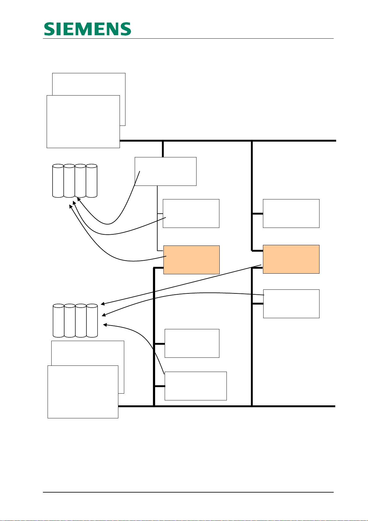
FB_xy -> e.g.
S7_IEC_S101
L1_xy
L2_xy
L7_T101_104_B
P_Application (Slave)
Send buffer
Slave
P_SLi (Slave)
ASDU-
Address
SL_Org_Asdu_1
(FB12x)
SLi_…
(FB130ff)
MAoSLi_MD
(FB161)
SLo_...
(FB135ff)
All blocks are multiple usable.
FB_xy -> e.g.
S7_IEC_S104
L1_xy
L2_xy
L7_T101_104_B
Slave-blocks (SL)
FB_100 -> e.g.
S7_IEC_M101
L1_xy
L2_xy
L7_T101_104_B
P_Application (Master)
FB_100 -> e.g.
S7_IEC_M104
L1_xy
L2_xy
L7_T101_104_B
MAo_…
(FC14xff)
MA_Org_Asdu_1
(FB12x)
MAi_...
(FB14xff)
Master-blocks (MA)
SLoMAi_CD
(FB166)
Send buffer
Master
3.1. Nodal blocks MAoSLi / SLoMAi
Slave
--------------------------------------------------------------------------------------------------------------------------------------------
Nodal-blocks
-------------------------------------------------------------------------------------------------------------------------------------------Master
SIPLUS RIC IEC on S7 V1.5 Page 8 of 28 ©SIEMENS AG 2013
Functional description I IA CE
Notice!
All application blocks are designed exclusively for the OB1 priority level. The FB100
communication blocks ('S7_IEC_Config') also have to be operated in priority level OB1!
Pre-condition for using the nodal blocks is the existence of minimum two IEC-channels in the system.
They mostly consist of an IEC-Slave (as interface to the control center) and an IEC-Master (interface to
the subordinated RTU).
Figure Nodal blocks:
The figure shows the „classical“ information flow from an subordinated station via the node to the control
center (monitoring direction, _MD) resp. from the control center via the node to the subordinated station
(command direction _CD).
Each of the node application blocks (,MaoSLi_MD and ,SloMAi_CD’) have one interface each to the
source and to the target application available, which have to be interconnected according to the following
description
MAoSLi_MD, for the monitoring direction
The flow direction of the information is:
Master (source) -> node -> Slave (target)
The application block , MAoSLi_MD’ is connected via the pointer ‚P_Application (Master)’ with the
‚S7_IEC_Config’ of the Master protocol version (information source) like the MAo-blocks. i.e. the func-
tional block will be linked directly to the IEC-Master-activation.
The link to the Slave-application (information target) is carried out like the activation of the SLi-blocks with
the pointer ‚P_SLi (Slave)’ via an organization block ‚SL_Org_Asdu_1’. The parameterized ASDUaddress from the ‚SL_Org_Asdu_1’ will be also used for the information of the nodal block.
SLoMAi_CD, for the command direction
The flow direction of the information is:
Slave (source) -> node -> Master (target)
The application block ,SLoMAi_CD’ is connected via the pointer ‚P_Application (Slave)’ with the
‚S7_IEC_Config’ of the Slave protocol version (information source) like the SLo-blocks.
The link to the Master-application (information target) is carried out with the pointer ‚P_Application (Mas-
ter)’ to the ‚S7_IEC_Config’ of the Master protocol version like the MAi-blocks.
SIPLUS RIC IEC on S7 V1.5 Page 9 of 28 ©SIEMENS AG 2013
 Loading...