

Siemens SIPLUS PSU Operating Instructions Manual

SIPLUS PSU
Power Supply Unit 6DL3500-8BA
Operating Instructions A5E00854207E
SIPLUS PSU (6DL3500-8BA)
General and safety information
Copyright
Copyright © Siemens AG 2018 All Rights Reserved
SIMATIC® and SIPLUS® are registered trademarks of the Siemens AG.
Liability disclaimer
We have checked that the contents of this document correspond to the hardware and software described. However, since deviations cannot be precluded entirely, we cannot guarantee full consistency.
The information in this document is regularly checked, however, and the necessary corrections included in subsequent editions. Suggestions for improvement are welcome. Technical data are subject to modifications.
Warning notices
These Operating Instructions contain information which you should observe in order to ensure your
own personal safety, as well to avoid material damage. The notices referring to your personal safety
are highlighted in the manual by a warning triangle. Notices referring only to equipment damage have
no safety alert symbol. Warnings are shown in descending order according to the degree of danger
as follows:
DANGER
indicates that death or serious injury will result if proper precautions are not
taken.
WARNING
indicates that death or serious injury may result if proper precautions are not
taken.
CAUTION
indicates that minor personal injury may result if proper precautions are not
taken.
NOTICE
means that material damage can occur if the appropriate precautions are not
taken.
Note
highlights important information about the product, handling the product, or part of the
documentation that is of particular importance.
In the event of a number of levels of danger prevailing simultaneously, the warning corresponding to the highest level of danger is always used. A warning that uses a safety
alert symbol indicating possible personal injury may also include a warning relating to
material damage.
SIPLUS PSU Power Supply Unit A5E00854207E 2 of 30
Copyright (C) Siemens AG 2018 V 8.00 released 2018-05-03

SIPLUS PSU (6DL3500-8BA)
Qualified personnel
The device/system must only be set up and used in conjunction with this documentation. Transport,
commissioning and operation of the device/system may only be performed by qualified personnel.
For the purpose of the safety information in these Operating Instructions, a "Qualified Person" is
someone who is authorized to energize, ground, and tag equipment, systems, and circuits in accordance with established safety procedures.
Correct usage of Siemens products
Please observe the following:
WARNING
Danger in case of none designated use of the product!
Serious injury may result.
Siemens products may only be used for the applications indicated in the catalog and in the relevant technical description. If third-party products and components are used, these must be recommended or approved by Siemens. To
ensure trouble-free and safe operation of the products, they must be appropriately transported, stored, assembled, installed, commissioned, operated and
maintained. The permitted environmental and ambient conditions must be adhered to. Notices in the relevant documentation must be observed.
CAUTION
Risk to be burnt!
Burns at the hands by hot surfaces of the equipment’s housing or the heat
sink!
Do not touch the surface of the housing and the heat sink and let it cool down
before an exchange.
Note
For ecologically compatible recycling and disposal of your old device, contact a certificated waste disposal service for electronic scrap. Please dispose the old device according to the local regulations in your country.
SIPLUS PSU Power Supply Unit A5E00854207E 3 of 30
Copyright (C) Siemens AG 2018 V 8.00 released 2018-05-03

SIPLUS PSU (6DL3500-8BA)
Electrostatic Sensitive Devices ESD
Almost all electronic devices and modules are equipped with highly integrated components or elements in MOS technology. For technological reasons, these electronic components are very sensitive
to overvoltage and, consequently, to electrostatic discharge.
The short designation for such electrostatic sensitive components/modules is: "ESD", which is the
commonly used international abbreviation ”ESD” (Electrostatic Sensitive Device).
NOTICE
Electrostatic Sensitive Devices ESD can be damaged!
The presence of this symbol on cabinet, rack or packaging labels indicates the
use of electrostatically sensitive devices and thus the touch sensitivity of the
respective modules. When touching the modules these can be damaged. This
can lead to an immediate failure or to a reduction of the life time of the modules.
Open the packing only at an ESD workplace. Discharge the body of your own
by establishing of an electrical connection to the earth potential before touching the module.
These modules can be destroyed by voltage and energy far below the limits of human perception.
Voltages of this kind occur as soon as a device or an assembly is touched by a person who is not
electrostatically discharged.
Components which were subject to such overvoltage are usually not recognized immediately as being
defective, because the malfunction does not occur until after a longer period of operation.
When working on the system, the following points must be followed exactly to ensure the safe discharge of electrostatic charges:
∂ Before performing any work on the system, create a ground connection by wearing a
wrist band.
∂ Always place or work on components on a grounded, conductive surface.
∂ Only transport components in suitable protective bags.
Tolerances of the prescribed tightening torques
Note:
If not indicated differently, the tolerances of the prescribed tightening torques in these
operating instructions are ±10 %.
SIPLUS PSU Power Supply Unit A5E00854207E 4 of 30
Copyright (C) Siemens AG 2018 V 8.00 released 2018-05-03

SIPLUS PSU (6DL3500-8BA)
Contents
General and safety information ................................................................................................... 2
1 List of abbreviation used ......................................................................................................... 6
2 Application ................................................................................................................................ 7
2.1 Utilization ............................................................................................................................... 7
2.2 Functions ............................................................................................................................... 7
3 Design ....................................................................................................................................... 8
3.1 Mechanical Structure.............................................................................................................. 8
3.2 Electrical Structure ................................................................................................................. 9
3.2.1 Block Diagram ............................................................................................................... 9
3.2.2 Electrical Terminals ....................................................................................................... 9
4 Mode of Operation .................................................................................................................. 10
4.1 Feeding ................................................................................................................................ 10
4.2 Sub-Distribution .................................................................................................................... 10
4.3 Fuse Protection .................................................................................................................... 10
4.4 Switching off the Supply Outputs ......................................................................................... 11
4.5 Monitoring and Signaling ...................................................................................................... 11
4.6 Signaling Outputs ................................................................................................................. 12
4.7 Signaling Scheme ................................................................................................................ 13
4.8 Earthing Concept ................................................................................................................. 14
4.9 Protective Equipment ........................................................................................................... 14
4.10 Checking of the Feeder Diodes ............................................................................................ 14
5 Technical Data ........................................................................................................................ 15
5.1 Mechanics ............................................................................................................................ 15
5.2 Environmental Conditions .................................................................................................... 15
5.3 Feeding ................................................................................................................................ 16
5.4 Supply Outputs..................................................................................................................... 17
5.5 Signaling Outputs ................................................................................................................. 18
6 Installation instruction ........................................................................................................... 19
6.1 Mounting position, heat dissipation and derating .................................................................. 19
6.2 Installation into the cabinet ................................................................................................... 20
6.3 Back-up fuse ........................................................................................................................ 20
7 Commissioning ....................................................................................................................... 21
7.1 Mounting into the instrumentation and control cabinet ......................................................... 21
7.2 Earthed Mounting ................................................................................................................. 23
7.3 Unearthed Mounting ............................................................................................................. 23
7.4 Inactivating of unused supply outputs .................................................................................. 23
8 Maintenance and Diagnosis ................................................................................................... 24
8.1 Self-Test Functions .............................................................................................................. 24
8.2 Malfunctions ......................................................................................................................... 24
8.3 Checking of the Feeder Diodes ............................................................................................ 25
8.4 Repair .................................................................................................................................. 27
8.5 Replace of an Equipment ..................................................................................................... 27
9 Order Designations ................................................................................................................ 29
10 Annex ....................................................................................................................................... 30
10.1 List of Figures ...................................................................................................................... 30
10.2 List of Tables ........................................................................................................................ 30
SIPLUS PSU Power Supply Unit A5E00854207E 5 of 30
Copyright (C) Siemens AG 2018 V 8.00 released 2018-05-03

SIPLUS PSU (6DL3500-8BA)
1 List of abbreviation used
AWG American Wire Gauge, coding for wire diameter
BGT Module rack
DC Direct current
DI Digital Input
EU902, EU903, EU905 Product name of FUM module racks of the SPPA-systems
FET Field-Effect-Transistor
FUM Function module of the SPPA module spectrum
H x W x D Height x width x depth
HC High Current
I & C Instrumentation and control
LED Light Emitting Diode
MELD Collective message output active HIGH
MELD_N Collective message output active LOW
PCS7 PC supported automation system S7
PELV Protective Extra Low Voltage according to EN 50178
PLC Programmable Logic Controller
PSU Power Supply Unit
SELV Safety Extra Low Voltage according to EN 60950-1
SIPLUS Siemens brand
SPPA Siemens Power Plant Automation
SIPLUS PSU Power Supply Unit A5E00854207E 6 of 30
Copyright (C) Siemens AG 2018 V 8.00 released 2018-05-03
SIPLUS PSU (6DL3500-8BA)
2 Application
2.1 Utilization
SIPLUS PSU is a power supply module in electronic cabinets for the feeding and sub-distribution of
the power supply DC 24 V. It was developed especially for use in instrumentation and control cabinets of the Siemens power station instrumentation and control systems SPPA-T2000 and SPPAT3000 and the Siemens automation system PCS7. It serves for the protected power supply of cabinet
components like racks, fans, heat exchangers, thermostats, door contacts and cabinet lamps.
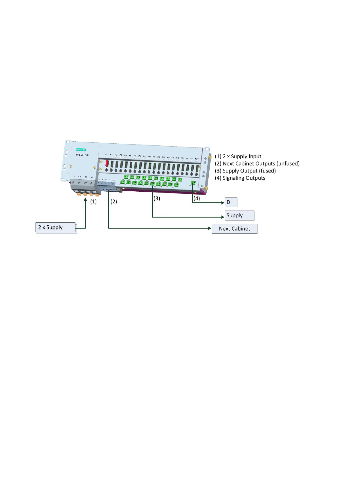
Figure 1: SIPLUS PSU
The SIPLUS PSU was designed for the installation into electronic cabinets with 19 inch modular design. By turning the lateral mounting angles by 180° backwards it can also be screwed to rear assembly walls without problems (see Chapter 7 “Commissioning”).
2.2 Functions
The SIPLUS PSU integrates the following functions in a compact unit:
∂ Redundant cabinet feeding power supply DC 24V
∂ Separate branch terminals DC 24V for the power supply of an adjacent cabinet
∂ 20 supply outputs for sub-distribution of the DC 24 V supply within the instrumentation and
control cabinet
∂ Fuse Protection of the cabinet sub-distribution
∂ Manual switch-off of every single electrical circuit of the cabinet sub-distribution
∂ Monitoring and signaling of a blown fuse or detection of a failure
∂ Indication of the operating state of all power supply outputs (X1-20) via LED displays
∂ Electrical connection of the ground potential M of the cabinet feeding with cabinet ground
∂ Disconnection of the earth connection for plants with central earth connection point
∂ Flexible installation by lateral assembly brackets with several fixing options
∂ Test of the feeder diodes with power supply in operating state
SIPLUS PSU Power Supply Unit A5E00854207E 7 of 30
Copyright (C) Siemens AG 2018 V 8.00 released 2018-05-03
3 Design
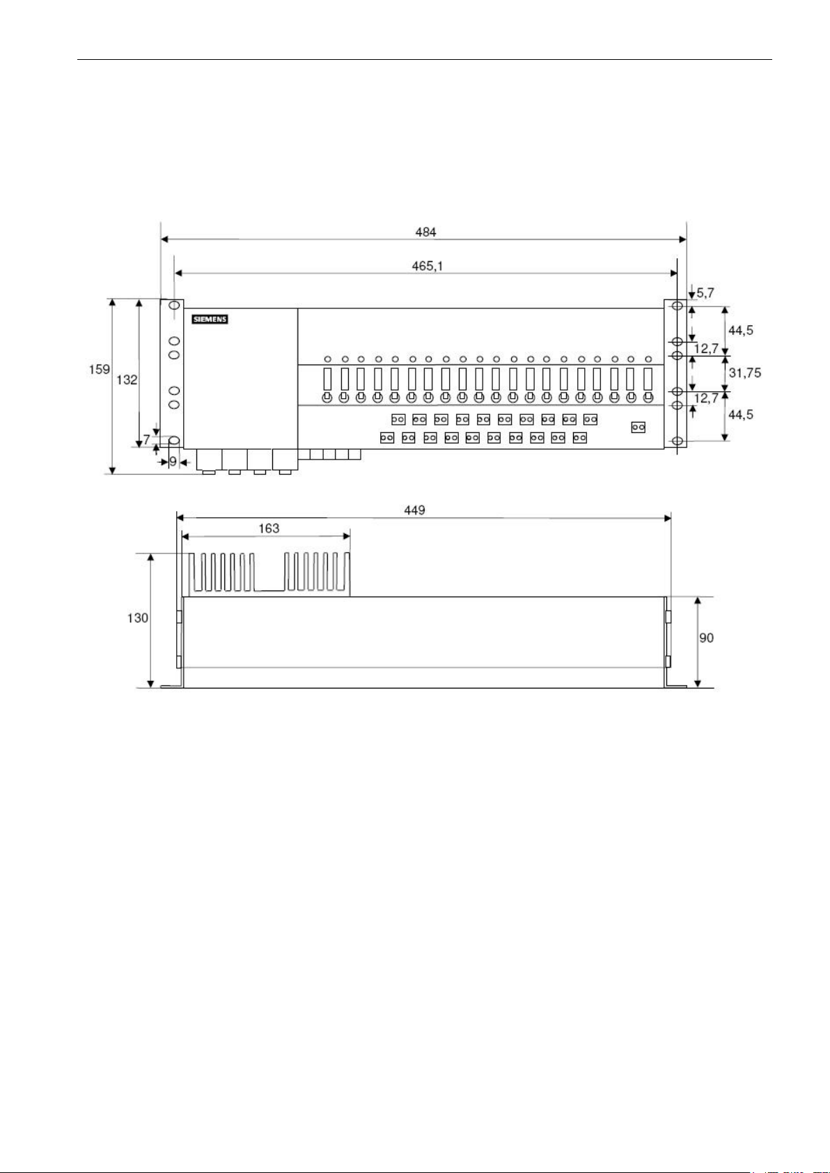
3.1 Mechanical Structure
SIPLUS PSU (6DL3500-8BA)
Figure 2: Physical dimensions of the SIPLUS PSU
SIPLUS PSU Power Supply Unit A5E00854207E 8 of 30
Copyright (C) Siemens AG 2018 V 8.00 released 2018-05-03
3.2 Electrical Structure
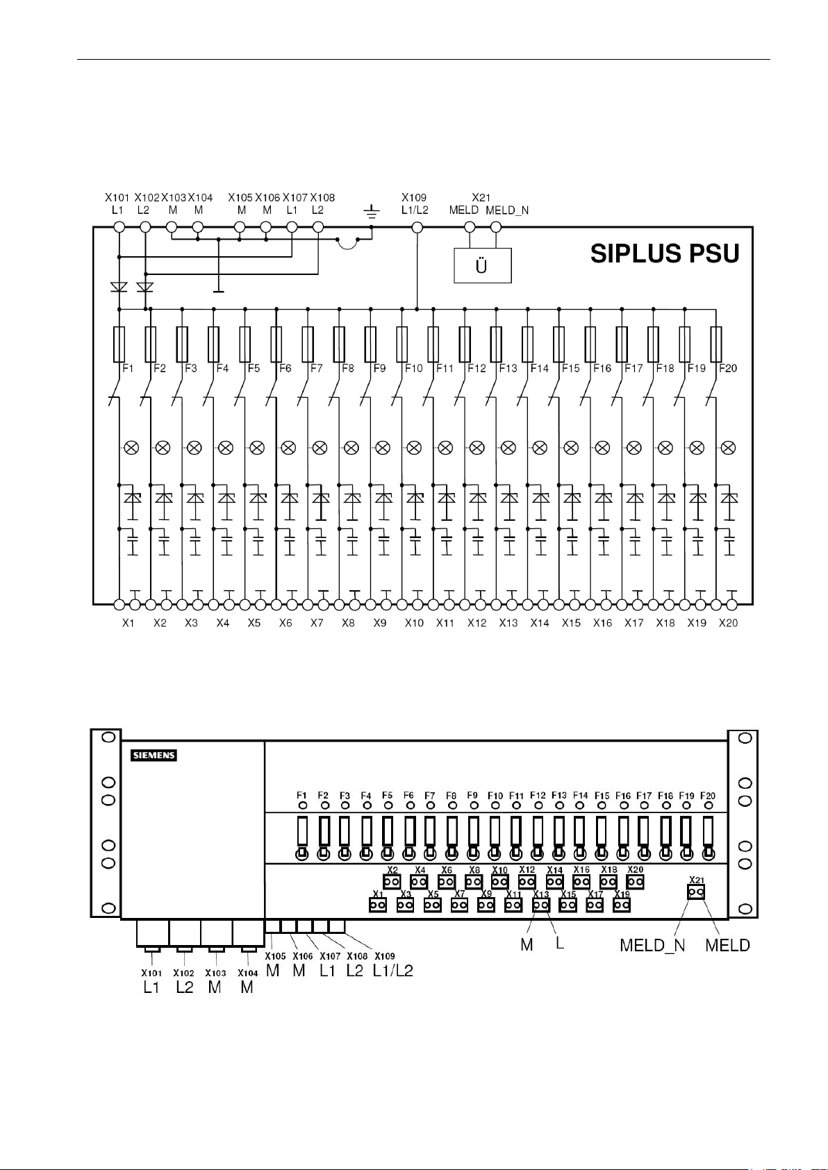
3.2.1 Block Diagram
SIPLUS PSU (6DL3500-8BA)
Figure 3: Block Diagram SIPLUS PSU
3.2.2 Electrical Terminals
Figure 4: Electrical Terminals SIPLUS PSU
SIPLUS PSU Power Supply Unit A5E00854207E 9 of 30
Copyright (C) Siemens AG 2018 V 8.00 released 2018-05-03
 Loading...