

Siemens SIPLUS HCS Series, SIPLUS HCS4300 PROFINET, SIPLUS HCS4300 PROFIBUS Operating Instructions Manual
Page 1
SIPLUS HCS4300 PROFINET/PROFIBUS DP
Page 2

Page 3

IO systems for heating elements
Heating control system
SIPLUS HCS4300
PROFINET/PROFIBUS DP
Operating Instructions
10/2019
A5E35452705A/005
Introduction
1
Safety guidelines
2
System overview
3
Application planning
4
Installing/mounting
5
Wiring
6
Commissioning
7
Configuring/Programming
8
Functions
9
Communications
10
Process and system
messages, error handling
11
Servicing and maintenance
12
Technical specifications
13
Appendix
A
Page 4

Siemens AG
Digital Industries
Postfach 48 48
90026 NÜRNBERG
GERMANY
A5E35452705A/005
Ⓟ
Copyright © Siemens AG 2014 - 2019.
All rights reserved
DANGER
indicates that death or severe personal injury will result if proper precautions are not taken.
WARNING
indicates that death or severe personal injury may result if proper precautions are not taken.
CAUTION
indicates that minor personal injury can result if proper precautions are not taken.
NOTICE
indicates that property damage can result if proper precautions are not taken.
WARNING
Siemens products may only be used for the applications described in the catalog and in the relevant technical
ambient conditions must be complied with. The information in the relevant documentation must be observed.
Legal information
Warning notice system
This manual contains notices you have to observe in order to ensure your personal safety, as well as to prevent
damage to property. The notices referring to your personal safety are highlighted in the manual by a safety alert
symbol, notices referring only to property damage have no safety alert symbol. These notices shown below are
graded according to the degree of danger.
If more than one degree of danger is present, the warning notice representing the highest degree of danger will
be used. A notice warning of injury to persons with a safety alert symbol may also include a warning relating to
property damage.
Qualified Personnel
The product/system described in this documentation may be operated only by personnel qualified for the specific
task in accordance with the relevant documentation, in particular its warning notices and safety instructions.
Qualified personnel are those who, based on their training and experience, are capable of identifying risks and
avoiding potential hazards when working with these products/systems.
Proper use of Siemens products
Note the following:
documentation. If products and components from other manufacturers are used, these must be recommended
or approved by Siemens. Proper transport, storage, installation, assembly, commissioning, operation and
maintenance are required to ensure that the products operate safely and without any problems. The permissible
Trademarks
All names identified by ® are registered trademarks of Siemens AG. The remaining trademarks in this publication
may be trademarks whose use by third parties for their own purposes could violate the rights of the owner.
Disclaimer of Liability
We have reviewed the contents of this publication to ensure consistency with the hardware and software
described. Since variance cannot be precluded entirely, we cannot guarantee full consistency. However, the
information in this publication is reviewed regularly and any necessary corrections are included in subsequent
editions.
11/2019 Subject to change
Page 5

Table of contents
1 Introduction ............................................................................................................................................. 9
1.1 Introduction ............................................................................................................................... 9
2 Safety guidelines ................................................................................................................................... 11
2.1 Safety notes ............................................................................................................................ 11
2.2 Security information ................................................................................................................ 13
2.3 Protective measures for the HCS4300 ................................................................................... 13
3 System overview ................................................................................................................................... 15
3.1 Area of application .................................................................................................................. 15
3.2 Features .................................................................................................................................. 16
3.3 System configuration .............................................................................................................. 18
3.4 Central interface module (CIM) ............................................................................................... 19
3.4.1 Function and design................................................................................................................ 19
3.5 Power output module (POM) .................................................................................................. 21
3.5.1 Function and design................................................................................................................ 21
3.6 I/O modules ............................................................................................................................. 25
3.6.1 PM4000 DI/DO ........................................................................................................................ 25
3.6.2 PM4000 U/I ............................................................................................................................. 26
3.6.3 PM4000 Temperature ............................................................................................................. 27
3.7 EM4315 expansion module .................................................................................................... 28
3.7.1 Design ..................................................................................................................................... 28
4 Application planning .............................................................................................................................. 29
4.1 Shipping .................................................................................................................................. 29
4.2 Storage ................................................................................................................................... 29
4.3 Scope of delivery .................................................................................................................... 30
4.4 Installation location ................................................................................................................. 31
4.5 POM4320 power rating ........................................................................................................... 34
4.6 Power rating of the POM4320 Highend .................................................................................. 36
4.7 POM4320 Highend power rating ............................................................................................ 38
4.7.1 POM4320 Highend for busbar adapter ................................................................................... 38
4.7.2 POM4320 Highend for wall mounting ..................................................................................... 40
SIPLUS HCS4300 PROFINET/PROFIBUS DP
Operating Instructions, 10/2019, A5E35452705A/005
3
Page 6

Table of contents
5 Installing/mounting ................................................................................................................................ 43
5.1 Requirements ......................................................................................................................... 43
5.2 Installing the Power Output Module (POM) ........................................................................... 44
5.2.1 Busbar mounting .................................................................................................................... 44
5.2.1.1 Preparations ........................................................................................................................... 44
5.2.1.2 Adjusting the busbar adapter ................................................................................................. 45
5.2.1.3 Mounting the POM (busbar adapter) ..................................................................................... 47
5.2.2 Panel mounting ...................................................................................................................... 48
5.2.2.1 POM mounting (panel mounting) ........................................................................................... 48
5.3 Installing the Central Interface Module .................................................................................. 49
5.4 Installing the EM4315 expansion module .............................................................................. 50
5.5 Installing the I/O module (PM) ............................................................................................... 51
6 Wiring ................................................................................................................................................... 53
6.1 Safety instructions and guidelines ......................................................................................... 53
6.2 Connecting the protective conductor ..................................................................................... 54
6.3 Connecting PROFINET and PROFIBUS fieldbus .................................................................. 55
6.4 Connect 24 V DC power supply ............................................................................................. 55
6.5 Connecting the heating elements and three-phase line supply ............................................. 57
6.5.1 Connecting the three-phase line supply ................................................................................ 57
6.5.2 Connecting heating elements ................................................................................................ 58
6.6 Block diagram POM4320 ....................................................................................................... 60
6.7 Block diagrams POM4320 Highend ....................................................................................... 61
6.7.1 Overview of connection types ................................................................................................ 61
6.7.2 Connection between phase and phase (400/480 V).............................................................. 62
6.7.3 Connection between phase and neutral conductor (230/277 V) ........................................... 70
6.8 Connecting system interfaces ................................................................................................ 72
6.9 Connecting I/O modules ........................................................................................................ 74
6.9.1 PM4000 DI/DO ....................................................................................................................... 74
6.9.2 PM4000 U/I ............................................................................................................................ 76
6.9.3 PM4000 Temperature ............................................................................................................ 78
7 Commissioning ..................................................................................................................................... 81
7.1 Requirements ......................................................................................................................... 81
7.2 Commissioning....................................................................................................................... 81
7.3 Insulation test ......................................................................................................................... 82
SIPLUS HCS4300 PROFINET/PROFIBUS DP
4 Operating Instructions, 10/2019, A5E35452705A/005
Page 7

Table of contents
8 Configuring/Programming ..................................................................................................................... 83
8.1 Integrating the HCS4300 into the PROFINET configuration .................................................. 83
8.2 Integrating the HCS4300 into the PROFIBUS configuration .................................................. 83
8.3 Device/hardware configuration in the TIA Portal .................................................................... 84
8.3.1 PROFINET device configuration ............................................................................................. 84
8.3.2 PROFIBUS device configuration ............................................................................................ 85
8.3.3 Configuration parameters ....................................................................................................... 86
8.3.3.1 CIM / POM configuration parameters ..................................................................................... 86
8.3.3.2 Configuration parameters for I/O modules ............................................................................. 89
8.4 Software tools for commissioning support .............................................................................. 91
8.4.1 Overview of tools for commissioning support ......................................................................... 91
8.5 Configuration control ............................................................................................................... 93
8.5.1 Configuration control ............................................................................................................... 93
8.5.2 Configuring .............................................................................................................................. 94
8.5.3 Control .................................................................................................................................... 94
8.5.3.1 Slot assignment ...................................................................................................................... 94
8.5.3.2 Control data record ................................................................................................................. 95
8.5.3.3 Feedback data record ............................................................................................................. 97
8.5.3.4 Transferring control data record in the startup program of the CPU ...................................... 98
8.5.3.5 Behavior during operation ..................................................................................................... 100
8.5.4 Examples of configuration control ......................................................................................... 100
8.5.4.1 Station master HCS4300 ...................................................................................................... 100
9 Functions ............................................................................................................................................ 105
9.1 Function overview ................................................................................................................. 105
9.2 Status and actual displays .................................................................................................... 106
9.3 Power output control ............................................................................................................. 106
9.3.1 Half-wave control .................................................................................................................. 106
9.3.2 Phase angle control .............................................................................................................. 108
9.3.3 Soft starting function ............................................................................................................. 109
9.3.4 Switch on heating .................................................................................................................. 110
9.3.5 Soft start during heater operation ......................................................................................... 111
9.3.6 Channel control via setpoints ................................................................................................ 111
9.3.7 Channel control via fields ...................................................................................................... 112
9.3.8 Line voltage compensation ................................................................................................... 113
9.3.9 Behavior of the power outputs .............................................................................................. 113
9.3.10 Power control ........................................................................................................................ 114
9.3.11 Parallel connection of channels ............................................................................................ 115
9.4 Digital inputs/outputs............................................................................................................. 116
9.5 Recording of analog measured line values........................................................................... 117
9.6 Recording of analog measured values ................................................................................. 118
SIPLUS HCS4300 PROFINET/PROFIBUS DP
Operating Instructions, 10/2019, A5E35452705A/005
5
Page 8

Table of contents
9.7 Monitoring functions ............................................................................................................. 119
9.7.1 Phase connection monitoring ............................................................................................... 119
9.7.2 Rotating-field test ................................................................................................................. 119
9.7.3 Line supply voltage monitoring ............................................................................................ 120
9.7.4 Monitoring of the 24 V DC supply voltage ........................................................................... 120
9.7.5 Frequency monitoring .......................................................................................................... 120
9.7.6 Temperature monitoring ....................................................................................................... 121
9.7.7 Power channel monitoring ................................................................................................... 122
9.7.8 Power channel monitoring for loads connected in parallel .................................................. 123
9.7.9 Current load monitoring ....................................................................................................... 123
9.7.10 Fault current monitoring ....................................................................................................... 123
9.7.11 Power control monitoring ..................................................................................................... 124
9.7.12 Monitoring of adaptive soft start ........................................................................................... 124
10 Communications .................................................................................................................................. 125
10.1 Cyclic data exchange ........................................................................................................... 125
10.1.1 Cyclic output data................................................................................................................. 125
10.1.2 Cyclic input data ................................................................................................................... 128
10.2 Acyclic data exchange ......................................................................................................... 131
10.2.1 Acyclic data exchange - Overview ....................................................................................... 131
10.2.2 Acyclic output data ............................................................................................................... 132
10.2.3 Acyclic input data ................................................................................................................. 137
10.3 Transfer of diagnostic alarms to the controller ..................................................................... 140
10.3.1 Transferring diagnostic alarms to the controller: PROFINET .............................................. 140
10.3.2 Transferring diagnostic alarms to the controller: PROFIBUS .............................................. 141
10.3.3 Manufacturer-specific error codes ....................................................................................... 141
11 Process and system messages, error handling .................................................................................... 145
11.1 Central Interface Module (CIM) ............................................................................................ 145
11.2 Power Output Module (POM) ............................................................................................... 146
11.2.1 LED operating display for POM ........................................................................................... 146
11.2.2 Fault reporting through diagnostics data ............................................................................. 146
11.3 I/O modules .......................................................................................................................... 148
12 Servicing and maintenance .................................................................................................................. 149
12.1 Maintenance work ................................................................................................................ 149
12.2 Firmware update .................................................................................................................. 149
12.2.1 PROFINET firmware update ................................................................................................ 149
12.2.2 PROFIBUS firmware update ................................................................................................ 151
12.3 Fuse replacement ................................................................................................................ 152
12.4 Replace fan .......................................................................................................................... 156
12.5 Replacing the Power Output Module (POM) ....................................................................... 158
12.6 Replacing the Central Interface Module (CIM) .................................................................... 160
12.7 Replacing an I/O module ..................................................................................................... 161
12.8 Recycling and disposal ........................................................................................................ 162
SIPLUS HCS4300 PROFINET/PROFIBUS DP
6 Operating Instructions, 10/2019, A5E35452705A/005
Page 9

Table of contents
13 Technical specifications ...................................................................................................................... 163
13.1 Technical specifications for CIM ........................................................................................... 163
13.2 Technical Specifications POM4320 ...................................................................................... 166
13.3 Technical Specifications POM4320 Highend ....................................................................... 176
13.4 Technical specifications for I/O module ................................................................................ 182
13.5 Technical specifications for EM4315 expansion module ...................................................... 192
13.6 Dimension drawings .............................................................................................................. 195
A Appendix............................................................................................................................................. 199
A.1 Certificates and approvals .................................................................................................... 199
A.1.1 Certificates and approvals .................................................................................................... 199
A.2 Article numbers for spare parts/accessories......................................................................... 200
A.2.1 Ordering data ........................................................................................................................ 200
A.3 ESD Guidelines ..................................................................................................................... 201
A.4 Service & Support ................................................................................................................. 203
A.4.1 Application example .............................................................................................................. 204
A.4.2 Frequently asked questions (FAQ) ....................................................................................... 204
Index................................................................................................................................................... 205
SIPLUS HCS4300 PROFINET/PROFIBUS DP
Operating Instructions, 10/2019, A5E35452705A/005
7
Page 10

Table of contents
SIPLUS HCS4300 PROFINET/PROFIBUS DP
8 Operating Instructions, 10/2019, A5E35452705A/005
Page 11

1
Edition
Comment
11/2014
First edition
module for additional 2 × 8 POMs
Commissioning support using PRONETA
04/2018
Expansion with phase control functionality for POM4320
10/2019
Expansion with POM4320 Highend
1.1 Introduction
Purpose of this documentation
These operating instructions contain the information you require to commission, operate and
service the HCS4300 heating control system.
Target group
The documentation is intended for qualified personnel in the following specialist fields:
● Operators, project engineers, programmers
● Electrically skilled personnel who assemble, connect and start up the device.
Required basic knowledge
● These operating instructions require prior knowledge of programming an S7 controller or
SIMOTION.
● Knowledge of working with the PROFINET or PROFIBUS fieldbus is also necessary.
History
The following earlier release versions of these operating instructions have been published:
10/2015 Expansion with POM with panel mounting, PROFIBUS, I/O modules, expansion
12/2016 Expansion with configuration control
SIPLUS HCS4300 PROFINET/PROFIBUS DP
Operating Instructions, 10/2019, A5E35452705A/005
9
Page 12

Introduction
Note
Applicable for devices up to firmware version 1.x of the CIM:
•
•
•
•
Applicable for devices up to firmware version 2.1 of the CIM:
•
•
Applicable for devices up to firmware version 2.3 of the CIM:
•
Applicable for devices as of firmware version 2.3 of the CIM:
•
Product label
Abbreviation
Central Interface Module
CIM
I/O module
PM
Power Output Module
POM
SIPLUS HCS4300
HCS
1.1 Introduction
Scope of the document
This document is valid for all components of the SIPLUS HCS4300 specified below and
describes the current delivery state.
A maximum of 6 POMs can be operated.
Expansion module, PMs and the DP connection are not available
The following applies for reading data records 152, 200 and 201: The information that is
read is always for the full configuration, i.e. for 54 channels or 6 POMs.
The data records 160, 190 and 202 are not available.
No phase control can be configured for a POM4320.
Data record 50 is not available.
POM4320 Highend cannot be configured.
The "Phase control" mode is only available for POM4320 with MLFB -0AA2 as of
HW version 02.
Naming conventions and abbreviations
Instead of product labels, the following abbreviations are also used in this document.
The following product labels and abbreviations are used:
Registered trademarks
SIPLUS ® is a registered trademark of Siemens AG.
SIPLUS HCS4300 PROFINET/PROFIBUS DP
10 Operating Instructions, 10/2019, A5E35452705A/005
Page 13
2
NOTICE
WARNING
Electric shock hazard
Can cause death or serious injury
WARNING
Electric shock hazard
Can cause death or serious injury
2.1 Safety notes
This device corresponds to the approvals printed on the type plate. If you have questions
about whether it is permissible to install the device in the planned environment, contact your
service representative.
• Alterations to the devices are not permitted. Failure to observe these guidelines shall
constitute a revocation of the approvals and manufacturer's warranty.
• The HCS4300 heating control system is not a safety product. In the event of a fault, the
machine must be brought to the safe state on the plant side.
Warning symbols on the device
When this warning symbol
instructions for the device. The operating instructions contain information about the
potential risks and enable you to recognize risks and implement countermeasures.
Note before connecting the device
The supply system to which the heating control system is connected must have a circuit
breaker. The device must be switched off and secured against switching on again, before
connecting to the line voltage. Otherwise, there is a risk of electric shock.
appears on the device, you must consult the operating
SIPLUS HCS4300 PROFINET/PROFIBUS DP
Operating Instructions, 10/2019, A5E35452705A/005
11
Page 14

Safety guidelines
WARNING
Electric shock hazard
Can cause death or serious injury
NOTICE
WARNING
No user-serviceable parts
Can cause death or serious injury
2.1 Safety notes
Working on the device or on components connected to it
• Voltages of more than 60 V can occur in the control cabinet. Suitable safety precautions
to prevent contact must therefore be taken before and during commissioning and
maintenance work.
• Before working on the heating control system or the connected components, ensure the
system is disconnected.
Fuse replacement
Use only the prescribed fuse types. If you operate a heating controller with unapproved
fuses, the device could be destroyed.
Repairs
Incorrectly performed repairs can result in substantial damage to equipment or endanger
the user. Return the device to Siemens for repair.
SIPLUS HCS4300 PROFINET/PROFIBUS DP
12 Operating Instructions, 10/2019, A5E35452705A/005
Page 15

Safety guidelines
NOTICE
2.2 Security information
2.2 Security information
Siemens provides products and solutions with industrial security functions that support the
secure operation of plants, systems, machines and networks.
In order to protect plants, systems, machines and networks against cyber threats, it is
necessary to implement – and continuously maintain – a holistic, state-of-the-art industrial
security concept. Siemens’ products and solutions constitute one element of such a concept.
Customers are responsible for preventing unauthorized access to their plants, systems,
machines and networks. Such systems, machines and components should only be
connected to an enterprise network or the internet if and to the extent such a connection is
necessary and only when appropriate security measures (e.g. firewalls and/or network
segmentation) are in place.
For additional information on industrial security measures that may be implemented, please
visit (https://www.siemens.com/industrialsecurity).
Siemens' products and solutions undergo continuous development to make them more
secure. Siemens strongly recommends that product updates are applied as soon as they are
available and that the latest product versions are used. Use of product versions that are no
longer supported, and failure to apply the latest updates may increase customers' exposure
to cyber threats.
To stay informed about product updates, subscribe to the Siemens Industrial Security
RSS Feed visit (https://www.siemens.com/industrialsecurity).
2.3 Protective measures for the HCS4300
Protective measures for the HCS4300 heating control system
Only authorized personnel are permitted to access the system and make changes to it.
SIPLUS HCS4300 PROFINET/PROFIBUS DP
Operating Instructions, 10/2019, A5E35452705A/005
13
Page 16

Safety guidelines
2.3 Protective measures for the HCS4300
SIPLUS HCS4300 PROFINET/PROFIBUS DP
14 Operating Instructions, 10/2019, A5E35452705A/005
Page 17

3
3.1 Area of application
The SIPLUS HCS 4300 heating control system is used to activate and switch heating
elements in industry, such as quartz, ceramic, flash, halogen or infrared emitters. It is of
modular design and can be flexibly adapted to suit the specific requirements of the
respective application.
Typical application areas are:
● PET blow molding
● Drying of enamels and coatings
● Thermal treatment of fabric and plastics
● Welding of plastic parts
● Handling of carbon materials
In general, the HCS4300 can be used wherever compact or modular concepts are required
with high levels of power output.
SIPLUS HCS4300 PROFINET/PROFIBUS DP
Operating Instructions, 10/2019, A5E35452705A/005
15
Page 18
System overview
3.2 Features
3.2 Features
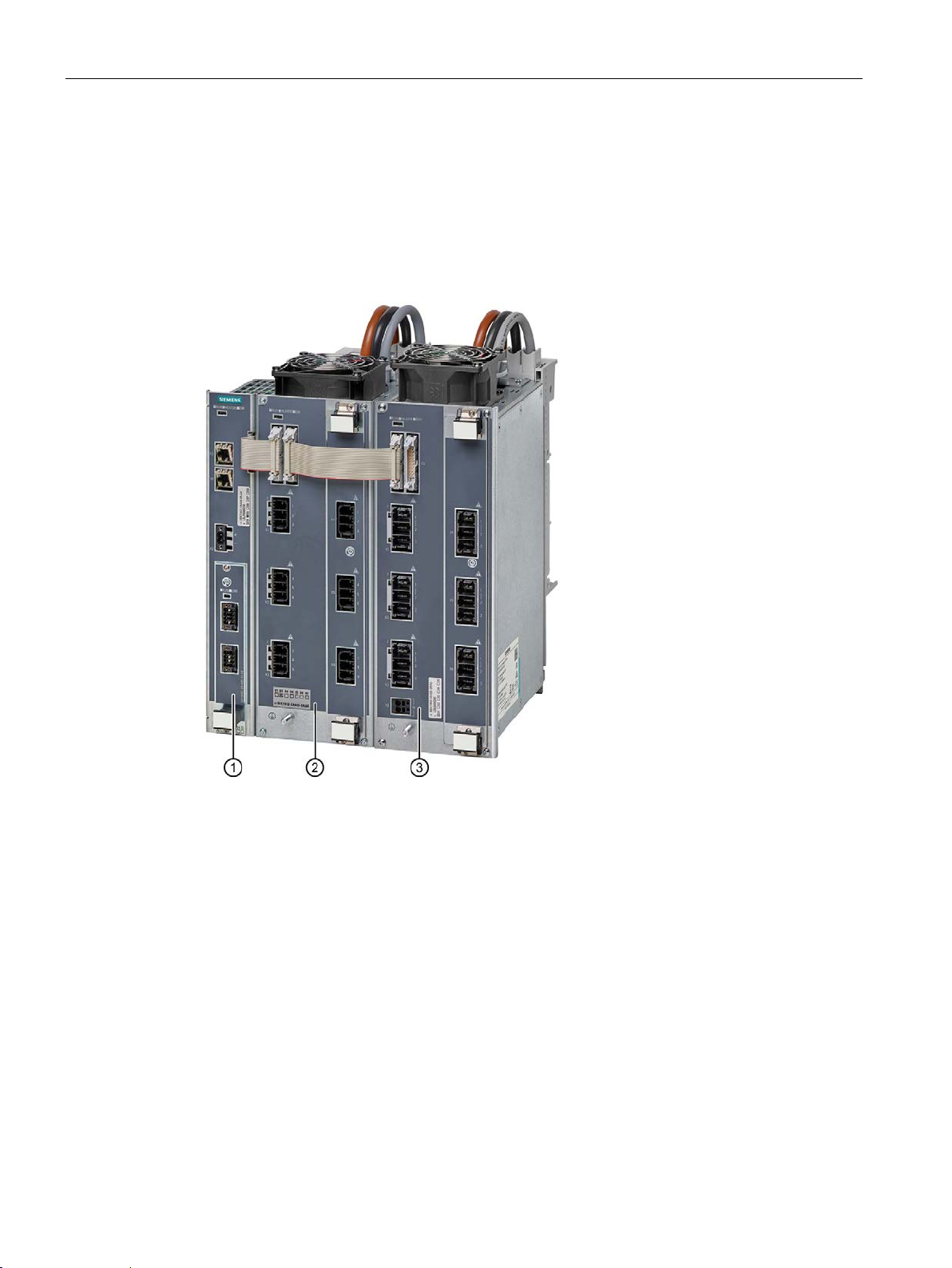
An HCS4300 system comprises one Central Interface Module (CIM) and up to
24 Power Output Modules (POM). As an option, one I/O module can be operated on
the CIM.
The following figure shows an example of an HCS4300, consisting of a CIM4310 for
PROFINET, a POM4320, as well as a POM4320 Highend for busbar mounting.
Figure 3-1 HCS4300 consisting of CIM ①, POM4320 ② and POM4320 Highend ③
SIPLUS HCS4300 PROFINET/PROFIBUS DP
16 Operating Instructions, 10/2019, A5E35452705A/005
Page 19

System overview
System component
Version
Description
a CIM.
line current.
4 measuring inputs for temperature
POM4320 or 6 POM4320 Highend.
3.2 Features
The following types of system component are available:
Features
Central Interface Module
(CIM)
I/O module
Power Output Module
(POM)
Expansion module
• CIM4310 PROFINET
• CIM4310 PROFIBUS
• PM4000 DI/DO
• PM4000 U/I
• PM4000 Temperature
• POM4320 busbar mounting
• POM4320 panel mounting
• POM4320 Highend busbar
mounting
• POM4320 Highend for panel
mounting
• EM4315
A maximum of 8 POM4320 or 6
POM4320 Highend can be operated at
8 digital outputs and 8 configurable
inputs/outputs.
Inputs for measuring line voltage and
4 analog inputs for 0 mA to 20 mA and
9 power outputs with diagnostic function and fault indication per channel.
6 power outputs with diagnostics and
error display per channel.
Enables operation of up to 8 additional
● Modular (centralized) and compact (distributed) configurations possible
● Communication via PROFINET/PROFIBUS
● Parameter assignment, commissioning, visualization and diagnostics via
Siemens TIA Portal
● Support of configuration and commissioning of the PROFINET network with PRONETA
● Integrated diagnostics and monitoring functions
● Control modes: Half-wave control, soft start and phase control
● Line voltage compensation for smoothing line voltage fluctuations integrated
● Only one 24 V power supply required for up to 8 POM4320 or 6 POM4320 Highend
● Slot for one I/O module (PM)
● Expansion module (optional) with 24 V power supply for operation of an additional
2 x 8 POM4320 or 2 x 6 POM4320 Highend
SIPLUS HCS4300 PROFINET/PROFIBUS DP
Operating Instructions, 10/2019, A5E35452705A/005
17
Page 20
System overview
3.3 System configuration
3.3 System configuration
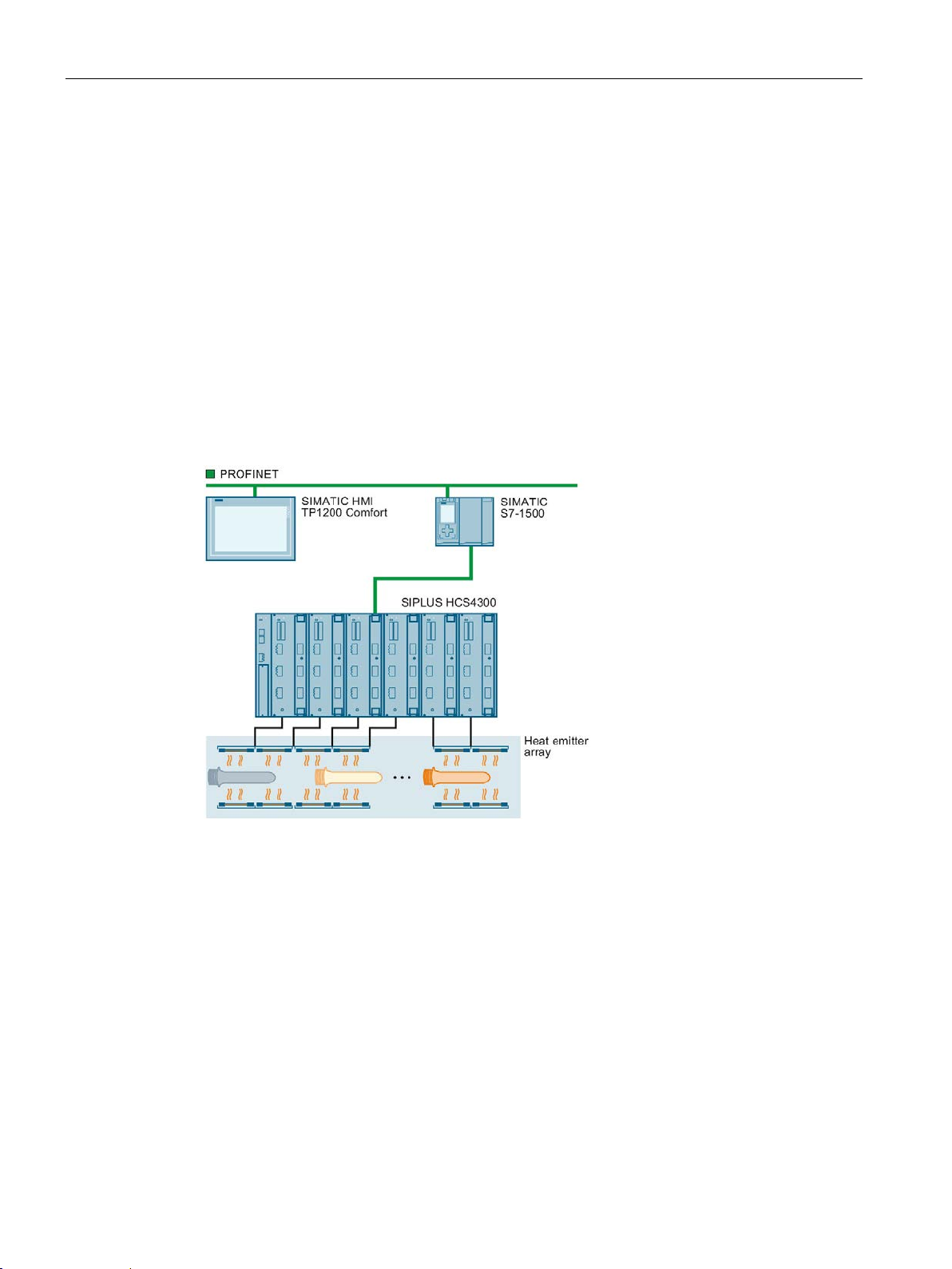
System components
A complete heating control system with HCS4300 includes the following components:
● Central Interface Module (CIM) 4310 with PROFINET or PROFIBUS
● Power Output Module (POM) 4320 for busbar or panel mounting
● Higher-level controller, e.g. SIMATIC S7-1500 automation system with
PROFINET/PROFIBUS
● Field PG, optional for commissioning and diagnostics
● HMI panel, optional, e.g. SIMATIC HMI TP1500
● Heat emitter array
Figure 3-2 System components
Centralized and distributed heating application
A maximum of 8 POM4320 or 6 POM4320 Highend can be operated at a CIM. In the
maximum configuration with 2 expansion modules, up 24 POM4320 or
18 POM4320 Highend can be operated.
System configurations can be realized for distributed, decentralized heating applications,
such as PET blow molding, where the heating controller is located below the heating boxes,
as well as central heating applications, for example, in thermoforming, where the heating
elements are implemented in numerous arrays and the modular heating control system is
located in a central control cabinet.
SIPLUS HCS4300 PROFINET/PROFIBUS DP
18 Operating Instructions, 10/2019, A5E35452705A/005
Page 21

System overview
3.4 Central interface module (CIM)
Communication via PROFINET or PROFIBUS
PROFINET combines the industrial experience of PROFIBUS with the openness and flexible
options of Ethernet. PROFINET enables high-speed and secure data exchange at all levels,
thus making it possible to implement innovative machine and plant concepts.
PROFIBUS has been established for years as the fieldbus for machines and plants. Based
on serial bus technology, it is the foundation for the distributed concepts that are common
today.
Combined operation with HCS4200 heating controller
You can operate a POM4320 with the HCS4200. See SIPLUS HCS4200
PROFINET/PROFIBUS DP operating instructions.
Combined operation of a POM4320 Highend with the HCS4200 heating controller is not
possible.
3.4 Central interface module (CIM)
3.4.1 Function and design
Function
The Central Interface Module (CIM) handles the communication with the higher-level
controller and with the connected Power Output Modules (POM). In addition, the CIM
provides the 24 V DC power supply for the connected POMs. The CIM is available in two
versions: with a PROFINET interface or with a PROFIBUS interface.
SIPLUS HCS4300 PROFINET/PROFIBUS DP
Operating Instructions, 10/2019, A5E35452705A/005
19
Page 22
System overview
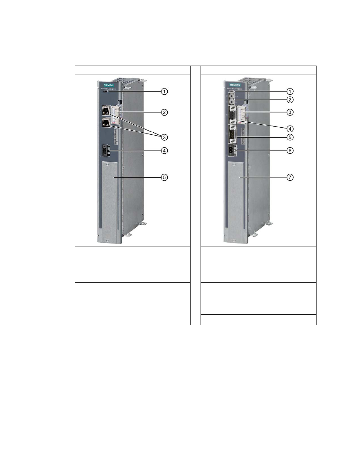
CIM4310 PROFINET
CIM4310 PROFIBUS
①
①
PROFIBUS
③
③
④
④
⑤
⑤
⑥
⑦
3.4 Central interface module (CIM)
Design
Status LEDs
System interface for POM
②
PROFINET interface X1 and X2
24 V DC supply X3
Slot for I/O module
Status LEDs
Address selector switches S1 and S2 for
②
System interface for POM
PROFIBUS DP interface X1
Service interface X2
24 V DC supply X3
Slot for I/O module
SIPLUS HCS4300 PROFINET/PROFIBUS DP
20 Operating Instructions, 10/2019, A5E35452705A/005
Page 23
System overview
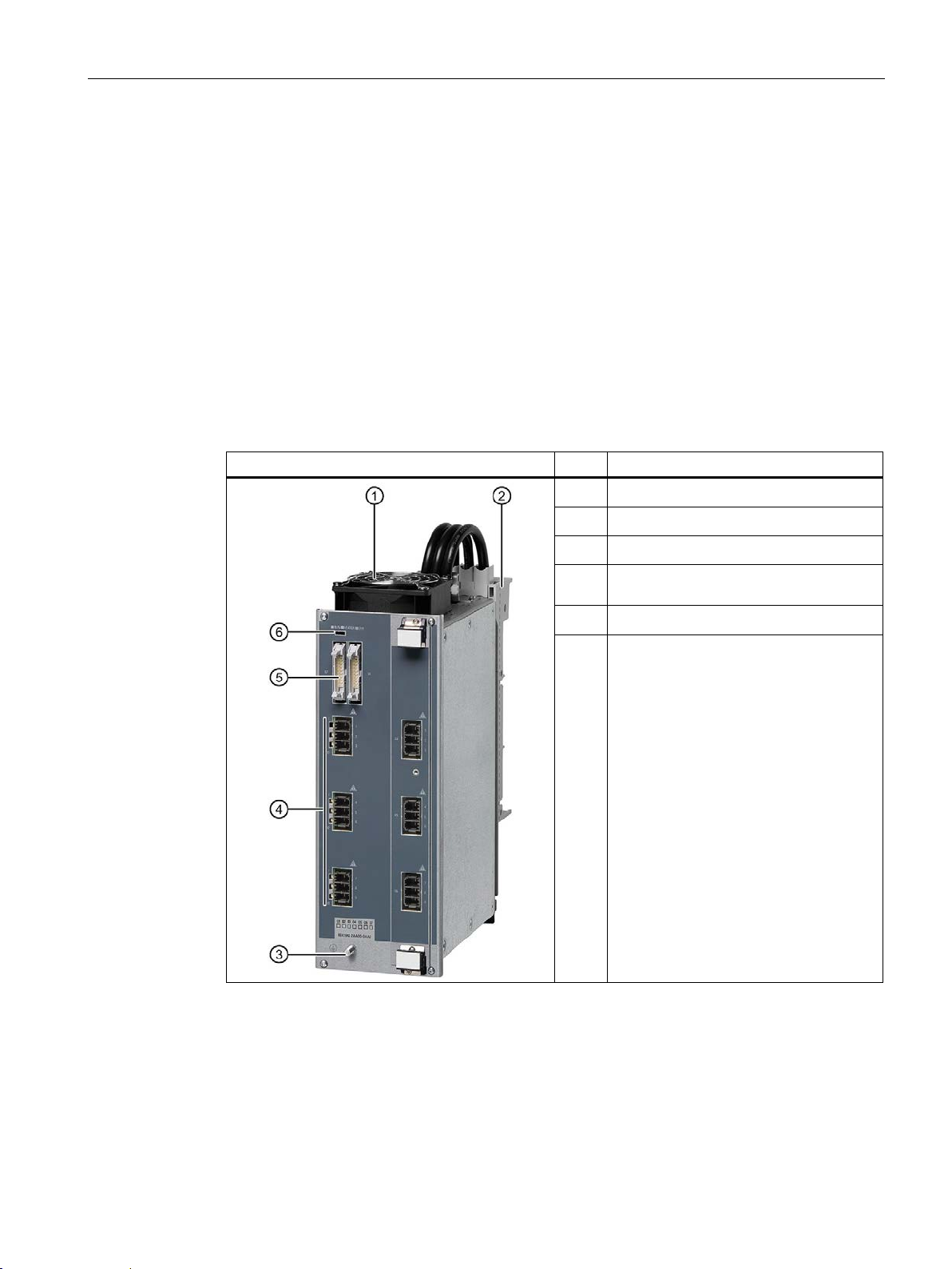
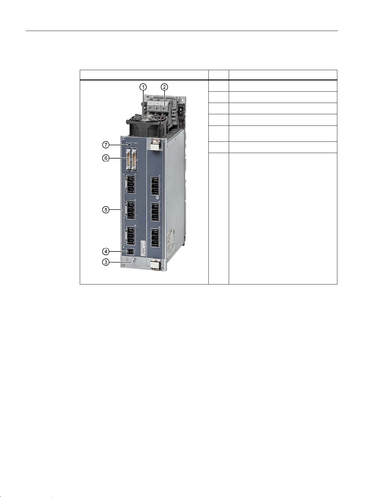
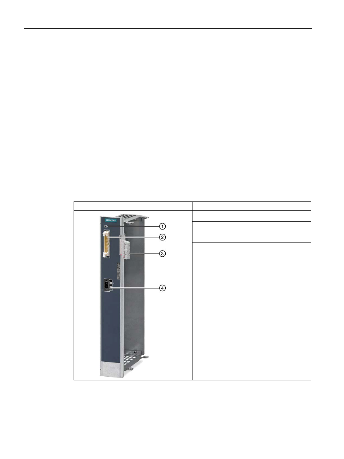
POM4320 for busbar mounting
Item
Description
①
②
③
④
error LED for each power output
⑤
3.5 Power output module (POM)
3.5 Power output module (POM)
3.5.1 Function and design
Function
The Power Output Module (POM) offers power outputs for resistive loads and can be
operated in TN and TT networks. The POM is available in versions for busbar or panel
mounting.
POM4320 design for busbar mounting
Fan
Busbar adapter
Protective conductor connector
3 x 3 power outputs including incoming,
HCS system interface
Status LEDs
⑥
SIPLUS HCS4300 PROFINET/PROFIBUS DP
Operating Instructions, 10/2019, A5E35452705A/005
21
Page 24
System overview
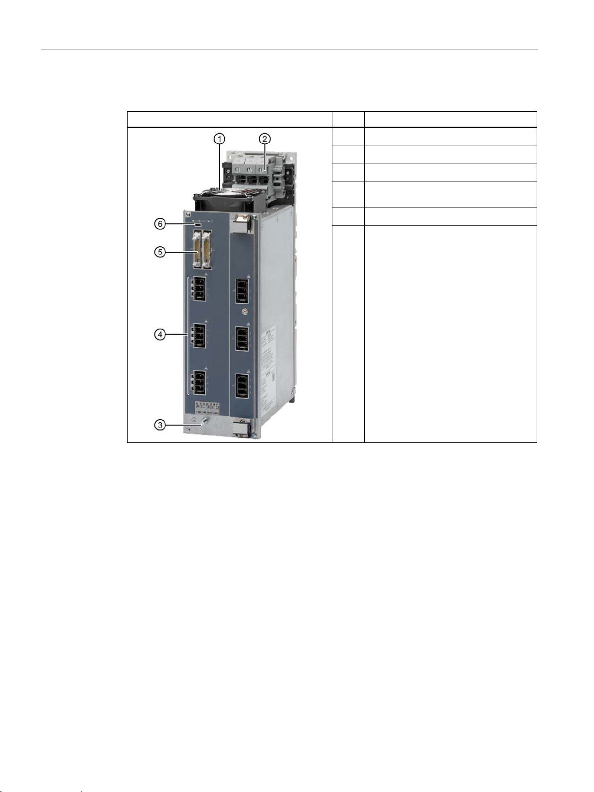
POM4320 for panel mounting
Item
Description
①
②
③
④
error LED for each power output
⑤
3.5 Power output module (POM)
POM4320 design for panel mounting
Fan
Mains connection L1, L2, L3
Protective conductor connector
3 x 3 power outputs including incoming,
HCS system interface
Status LEDs
⑥
SIPLUS HCS4300 PROFINET/PROFIBUS DP
22 Operating Instructions, 10/2019, A5E35452705A/005
Page 25
System overview
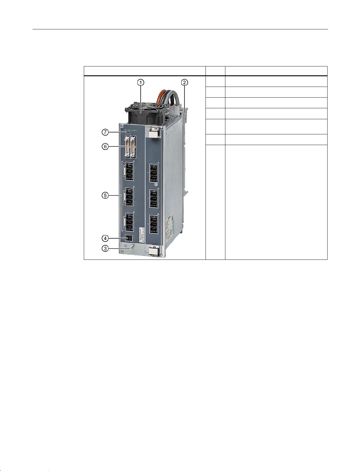
POM4320 Highend for busbar mounting
Item
Description
①
②
③
④
⑤
error LED for each power output
⑥
3.5 Power output module (POM)
POM4320 Highend design for busbar mounting
Fan
Busbar adapter
Protective conductor connector
Neutral conductor
3 x 2 power outputs including incoming,
HCS system interface
Status LEDs
⑦
SIPLUS HCS4300 PROFINET/PROFIBUS DP
Operating Instructions, 10/2019, A5E35452705A/005
23
Page 26
System overview
POM4320 Highend for panel mounting
Item
Description
①
②
③
④
⑤
error LED for each power output
⑥
3.5 Power output module (POM)
POM4320 Highend design for panel mounting
Fan
Mains connection L1, L2, L3
Protective conductor connector
Neutral conductor
3 x 2 power outputs including incoming,
HCS system interface
Status LEDs
⑦
SIPLUS HCS4300 PROFINET/PROFIBUS DP
24 Operating Instructions, 10/2019, A5E35452705A/005
Page 27
System overview
NOTICE
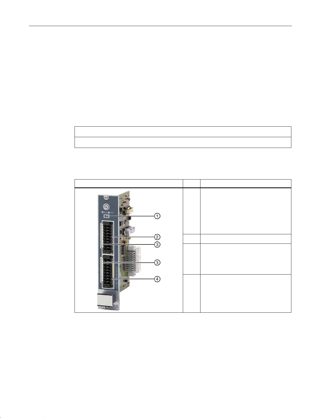
PM4000 DI/DO
Item
Description
②
3.6 I/O modules
3.6 I/O modules
3.6.1 PM4000 DI/DO
Function
The I/O module PM4000 DI/DO provides 8 digital outputs and 8 configurable inputs/outputs.
The digital I/O modules are controlled by the S7-CPU using the process image.
The PM4000 DI/DO must not be used for safety-relevant functions.
Design
Status LEDs
①
• RUN LED lights up green:
– Power ON
– Initialization status
• ERR LED lights up red:
fault
Digital outputs 1 … 8
LED to display switching status,
③
one LED each per input/output
• LED on: H state
• LED off: L state
Digital inputs/outputs 9 … 16,
④
switchable per channel
SIPLUS HCS4300 PROFINET/PROFIBUS DP
Operating Instructions, 10/2019, A5E35452705A/005
25
Page 28
System overview
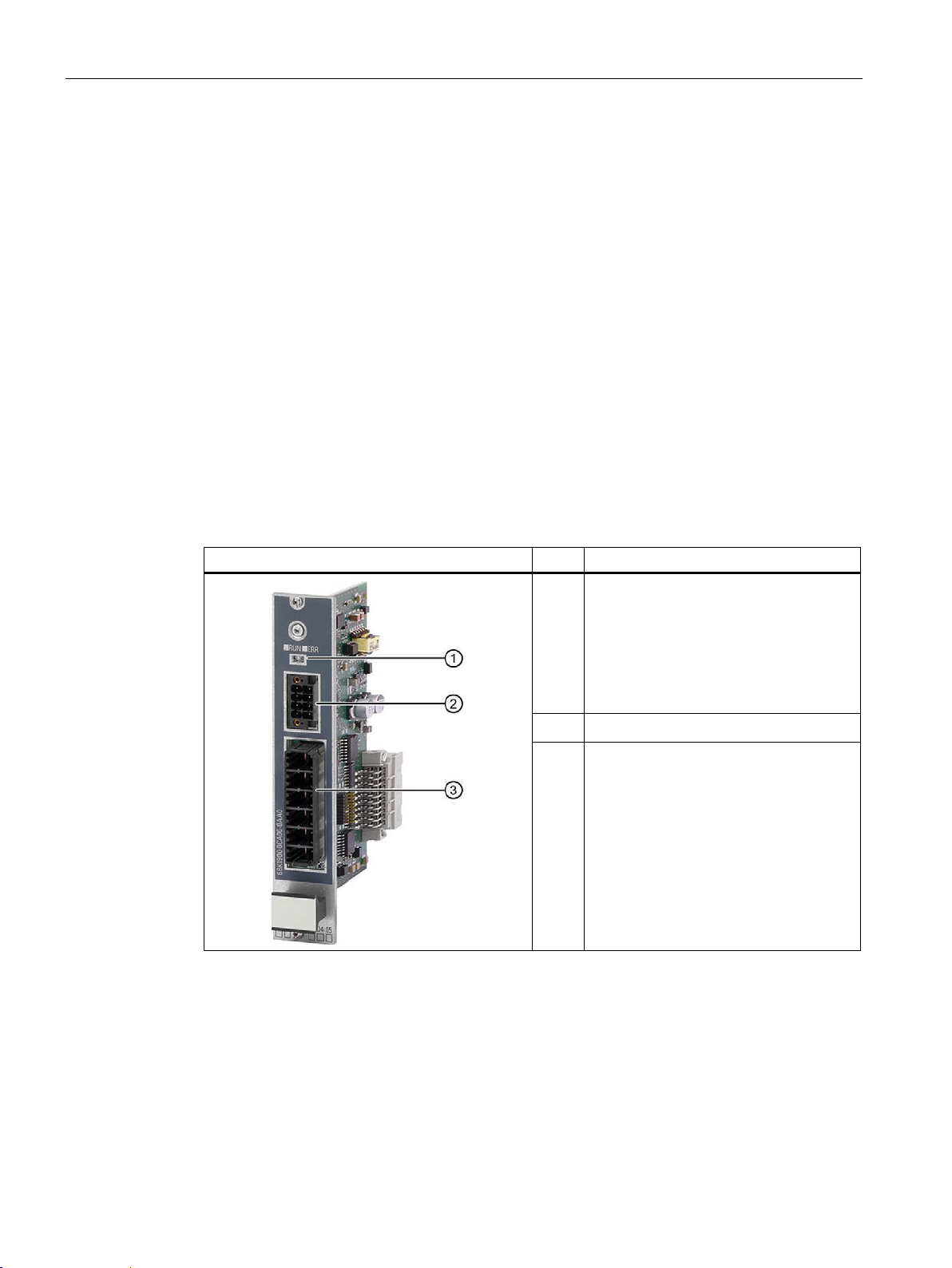
PM4000 U/I
Item
Description
②
③
3.6 I/O modules
3.6.2 PM4000 U/I
Function
The I/O module PM4000 U/I provides inputs for measuring mains voltage and mains current.
● Voltage measurement
Either the supplied line-to-line voltage or the star voltage is measured (parameterizable)
The rms effective value is calculated from the measured values.
● Phase current measurement
Three current transformers can be connected to the module (L1, L2, L3). The rms
effective value is calculated from the measured values. The measuring accuracy depends
on the current transformers used.
The measured values are transferred via the fieldbus and can be evaluated and further
processed by the user.
Design
Status LEDs
①
• RUN LED lights up green:
– Power ON
– Initialization status
• ERR LED lights up red:
Fault
Measuring inputs, line current
Measuring inputs mains voltage
SIPLUS HCS4300 PROFINET/PROFIBUS DP
26 Operating Instructions, 10/2019, A5E35452705A/005
Page 29
System overview
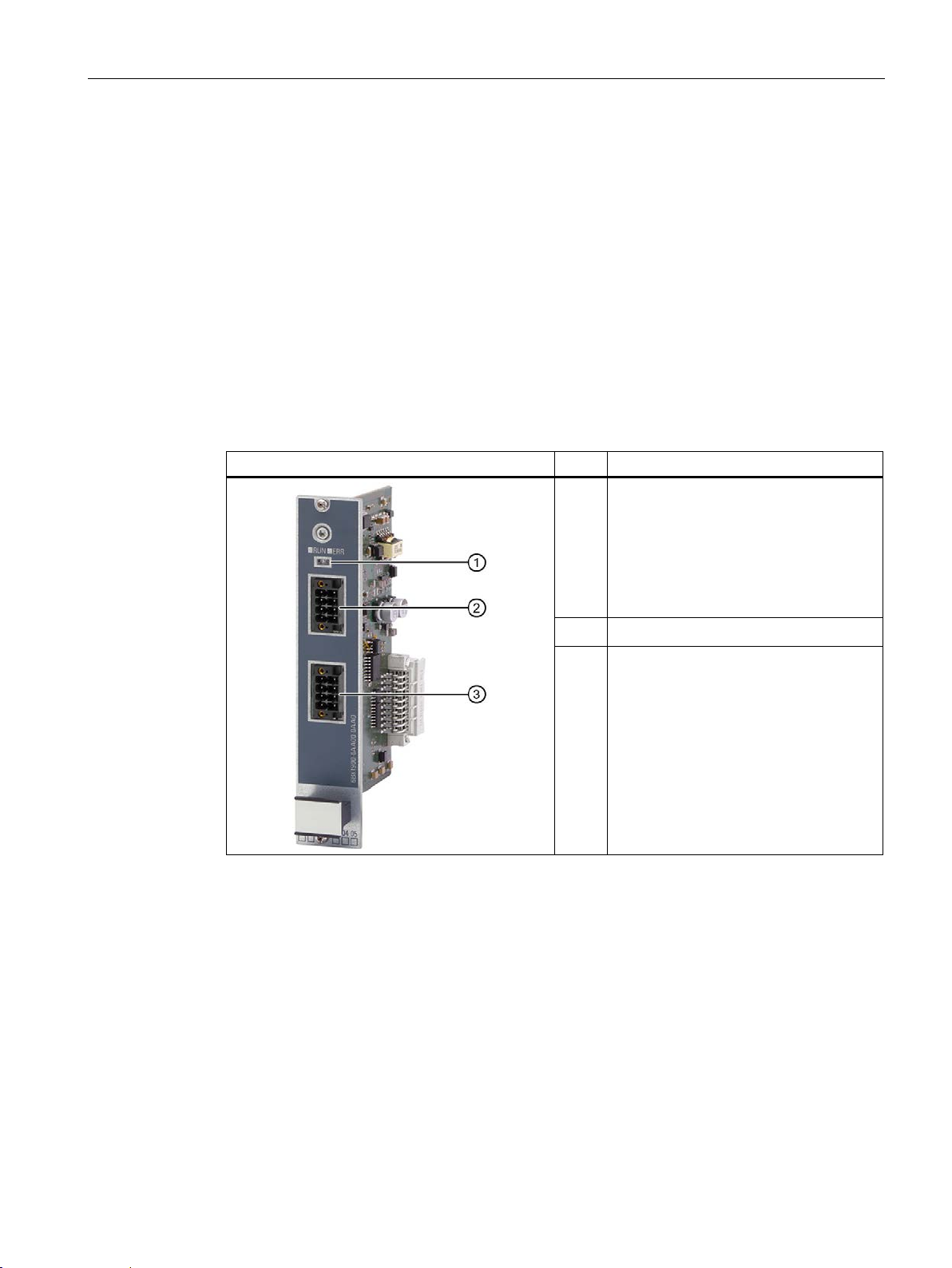
PM4000 Temperature
Item
Description
②
③
3.6 I/O modules
3.6.3 PM4000 Temperature
Function
I/O module temperature for HCS Central Interface Module (CIM).
● Four measuring inputs for temperature in two-wire technology or two measuring inputs for
temperature in four-wire technology.
● Four analog inputs for 0 mA to 20 mA
The measured values are transferred via the fieldbus and can be evaluated and further
processed by the user.
Design
Status LEDs
①
• RUN LED lights up green:
– Power ON
– Initialization status
• ERR LED lights up red:
fault
Analog inputs 1 … 4
Measuring inputs 1 … 4 for temperature
SIPLUS HCS4300 PROFINET/PROFIBUS DP
Operating Instructions, 10/2019, A5E35452705A/005
27
Page 30
System overview
EM4315 expansion module
Item
Description
①
②
③
④
3.7 EM4315 expansion module
3.7 EM4315 expansion module
3.7.1 Design
Function
In the basic configuration with one CIM, a maximum of 8 POM4320 or 6 POM4320 Highend
can be operated. An EM4315 expansion module enables operation of up to 8 additional
POM4320 or 6 POM4320 Highend is possible.
Two EM4315 expansion modules can be used in the maximum configuration. This means
the following can be operated on one CIM in total:
● 24 POM4320 or
● 18 POM4320 Highend
Design
Status LEDs
System interface to last POM
System interface to next POM
24 V DC supply
SIPLUS HCS4300 PROFINET/PROFIBUS DP
28 Operating Instructions, 10/2019, A5E35452705A/005
Page 31

4
NOTICE
Damage to the device
NOTICE
Damage to the device
4.1 Shipping
Shipping
The device can be damaged by inappropriate shipping. Transport the device, therefore,
only in the original packaging. This will give it the necessary protection against shock and
impact.
Lifting and carrying the power output module (POM)
The power output module (POM) is connected to the busbar adapter with 3 leads.
Do not use these leads to lift or carry the POM.
4.2 Storage
It is absolutely essential that the device is stored in compliance with the storage conditions
as described in Chapter Technical specifications (Page 163). In the event of ingress of dirt or
liquid into the equipment, formation of condensation, damage or any other failures to comply
with the prescribed storage conditions, the equipment must not be commissioned until the
correct remedial procedure has been discussed with Siemens AG.
SIPLUS HCS4300 PROFINET/PROFIBUS DP
Operating Instructions, 10/2019, A5E35452705A/005
29
Page 32

Application planning
Component
Included in the scope of supply
NOTICE
Damage to the system
4.3 Scope of delivery
4.3 Scope of delivery
Depending on the components ordered, the scope of delivery includes:
HCS4300 CIM
HCS POM4320
HCS POM4320 Highend
EM4315 expansion module
HCS PM4000 temperature
HCS PM4000 DI/DO
HCS PM4000 U/I
• CD with license information (CIM PROFINET)
• 1 plug connector, 2-pin
• Compact operating instructions
• Connecting cables 100 mm for system interface
• 6 plug connectors for connecting heating elements
• Compact operating instructions
• Connecting cables 100 mm for system interface
• 3 plug connectors for connecting heating elements
• Compact operating instructions
• Compact operating instructions
• 1 plug connector, 2-pin
• Compact operating instructions
• 2 plug connectors, 8-pin
• Compact operating instructions
• 2 plug connectors, 18-pin
• Compact operating instructions
• One 6-pin and one 8-pin plug connector
Unpacking and checking the delivery
SIPLUS HCS4300 PROFINET/PROFIBUS DP
30 Operating Instructions, 10/2019, A5E35452705A/005
1. Unpack the device.
2. Make sure that the package is complete.
3. Check the device for transport damage by visual inspection.
Damaged parts can result in damage to the system. Only put undamaged parts into
operation.
Page 33

Application planning
Note
Installation in control cabinet/device connection box
The SIPLUS HCS4300 heating control system is intended for installation in a control cabinet
or a device connection box.
•
•
•
NOTICE
Damage due to overheating
4.4 Installation location
4.4 Installation location
Installation location requirements
In these cases, only the LEDs on the front of the device will remain visible during
commissioning. Take this into consideration for subsequent operation of the device.
The control cabinet / device connection box must satisfy the regulations regarding fire-
protection housing.
Ensure that all cables and leads that protrude externally are equipped with adequate
strain relief.
Mounting position and clearance dimensions
You must comply with all the instructions regarding the installation site and mounting
position. Otherwise the device might malfunction or incur permanent damage as a result of
overheating.
● The device is installed and operated vertically.
● Ensure that the permissible ambient temperature range is not exceeded
(see section Technical specifications (Page 163)).
● Maintain the minimum clearances from walls and other devices:
– Sides 0 mm (side-by-side mounting permitted), top 100 mm, bottom 100 mm for
ventilation and deaeration
Degree of pollution
SIPLUS HCS4300 is designed for pollution degree 2. According to the EN 50178 standard,
pollution degree 2 is non-conductive pollution under normal circumstances, which can,
however, become temporarily conductive as a result of condensation when the device is not
in service.
SIPLUS HCS4300 PROFINET/PROFIBUS DP
Operating Instructions, 10/2019, A5E35452705A/005
31
Page 34

Application planning
NOTICE
Damage to the device
4.4 Installation location
Overvoltage protection 24 V DC power supply
Inadequately dimensioned overvoltage protection can result in severe damage to the
device.
Always ensure, therefore, that the overvoltage protection is adequate (see section
Connect 24 V DC power supply (Page 55)).
Power loss of the POM4320
When planning and designing the cabinet cooling, take into consideration the power loss of
the POMs. The power loss of a POM is calculated as follows:
P
P
= P
LossPOM
vChannel (x)
LossChannel1
= I(x)2 • 0.04 Ω + I(x) • 0.8 V
x represents the channel number
This power loss occurs at 100% activation of the channels. If the channels are not 100%
activated, the power loss P
Power loss of the POM4320 Highend
The calculation formula specified for the POM4320 also applies to the POM4320 Highend
with internal incoming fuse.
If the incoming fuse is missing (e.g. with star connection or the fuse is implemented
externally), the following formula applies:
P
vChannel (x)
= I(x)2 • 0.033 Ω + I(x) • 0.8 V
+ P
LossChannel2
LossChannel (x)
+ ... + P
LossChannel9
+ 6 W
reduces proportionately.
SIPLUS HCS4300 PROFINET/PROFIBUS DP
32 Operating Instructions, 10/2019, A5E35452705A/005
Page 35

Application planning
NOTICE
Restriction of the switching power
4.4 Installation location
Restriction of the switching power
Due to the different physical properties of heat emitters, restrictions can be imposed on their
permissible switching capacity depending on the type of heat emitter.
Short-wave halogen or infrared emitters ("flash emitters") have a high starting current due to
their relatively low cold resistance. The starting current can be several times the rated
current, especially during the first half waves.
Overloading of the internal fuses of the POM can occur depending on the number of
switching operations as well as the duration of switching operations and pause times.
The power limit for each POM is set by the technical parameter "Current carrying capacity
per output, max. for heating elements with high inrush current"
(see Technical specifications (Page 163)) for each POM.
Therefore, we recommend you to have Siemens AG measure radiation sources with a high
inrush current
In this regard, read the information about using Category AC 3 contactors (see
Connecting the three-phase line supply (Page 57)).
Selection of the incoming fuse for POM4320 Highend
Depending on the selected connection type, an incoming fuse is also required for the
POM4320 Highend. This fuse must only meet the requirements for line protection. This
means that gG fuses of size 14x51 can be used. The nominal value of the current depends
on the connected load.
Recommended fuses: e.g. Siemens SENTRON, cylindrical fuse-link, 14x51 mm, 3NW61
If you connect channels in parallel, only one fuse is possible up to a current of 50 A. You
must use 2 identical fuses for higher values. For UL applications, use the same fuses as for
fusing the outgoing line.
Derating of fuses
Note that fuses are subject to derating at high ambient temperatures, i.e. the rated current
for a fuse is reduced.
SIPLUS HCS4300 PROFINET/PROFIBUS DP
Operating Instructions, 10/2019, A5E35452705A/005
33
Page 36
Application planning
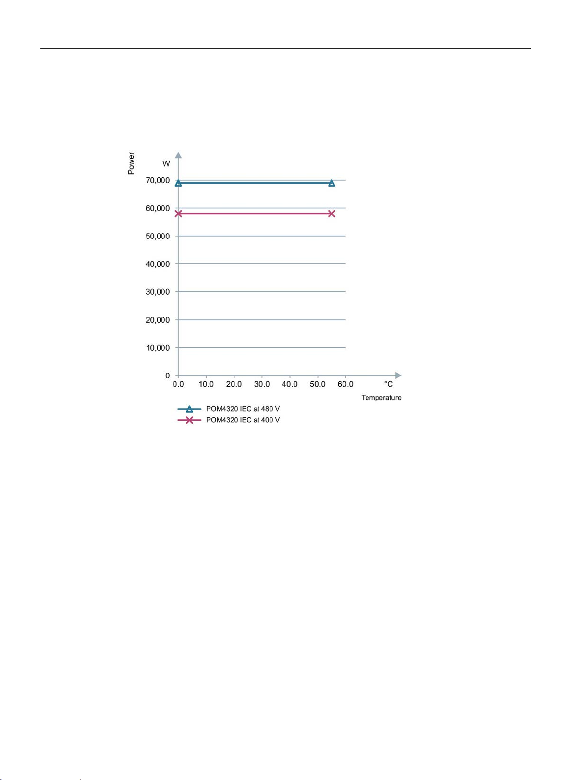
4.5 POM4320 power rating
4.5 POM4320 power rating
POM4320 IEC power rating
Figure 4-1 POM4320 IEC power rating
SIPLUS HCS4300 PROFINET/PROFIBUS DP
34 Operating Instructions, 10/2019, A5E35452705A/005
Page 37
Application planning
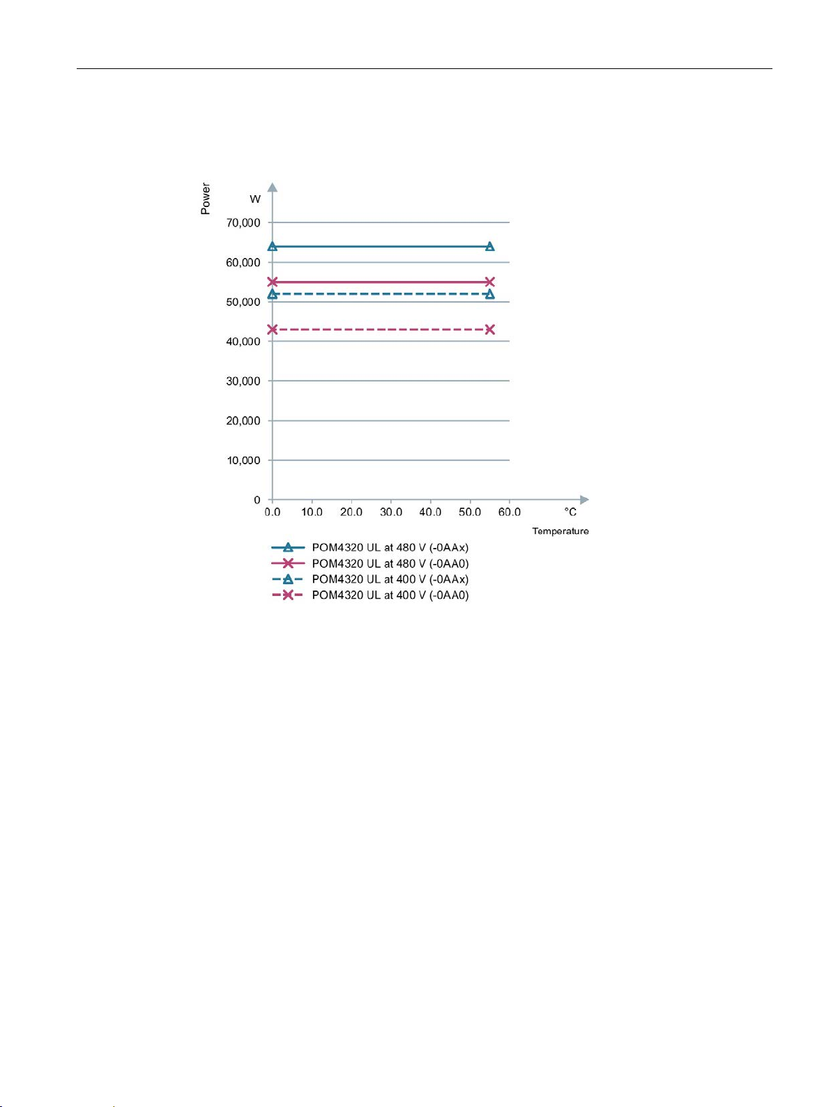
4.5 POM4320 power rating
Power rating POM4320 UL
Figure 4-2 POM4320 UL power rating
SIPLUS HCS4300 PROFINET/PROFIBUS DP
Operating Instructions, 10/2019, A5E35452705A/005
35
Page 38
Application planning
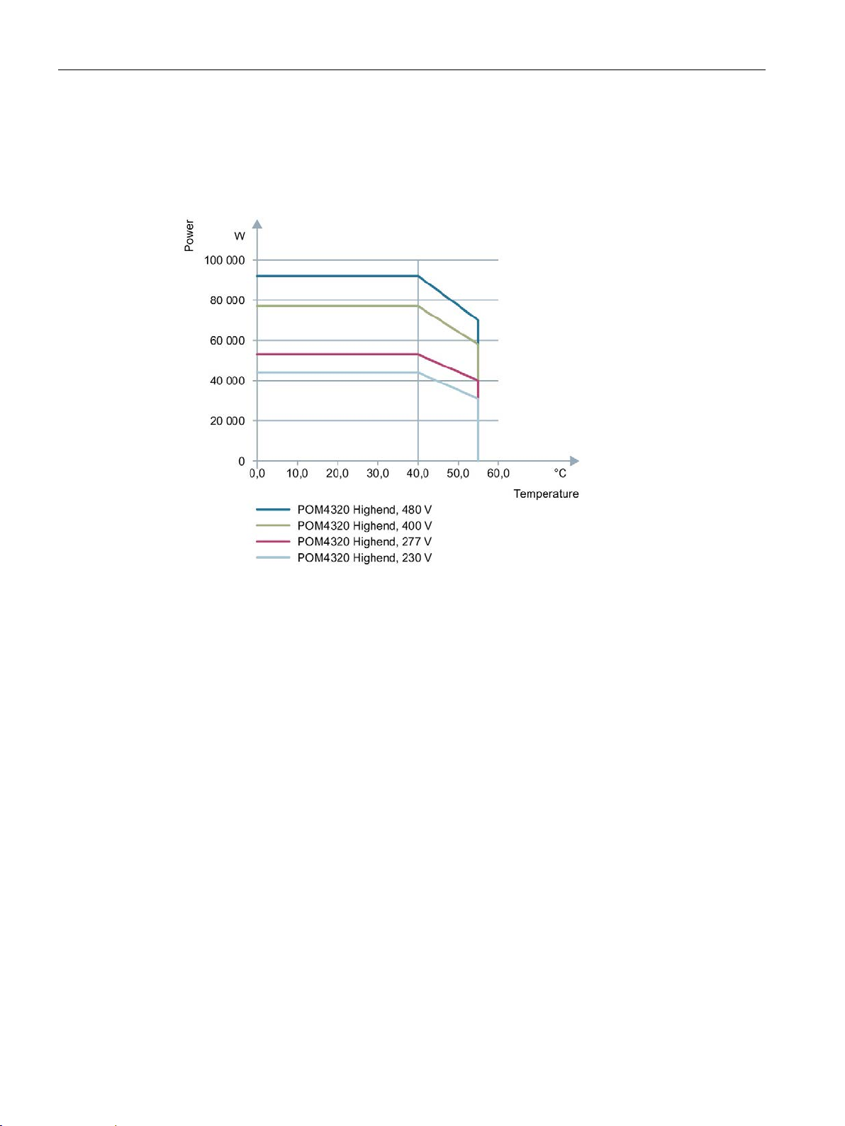
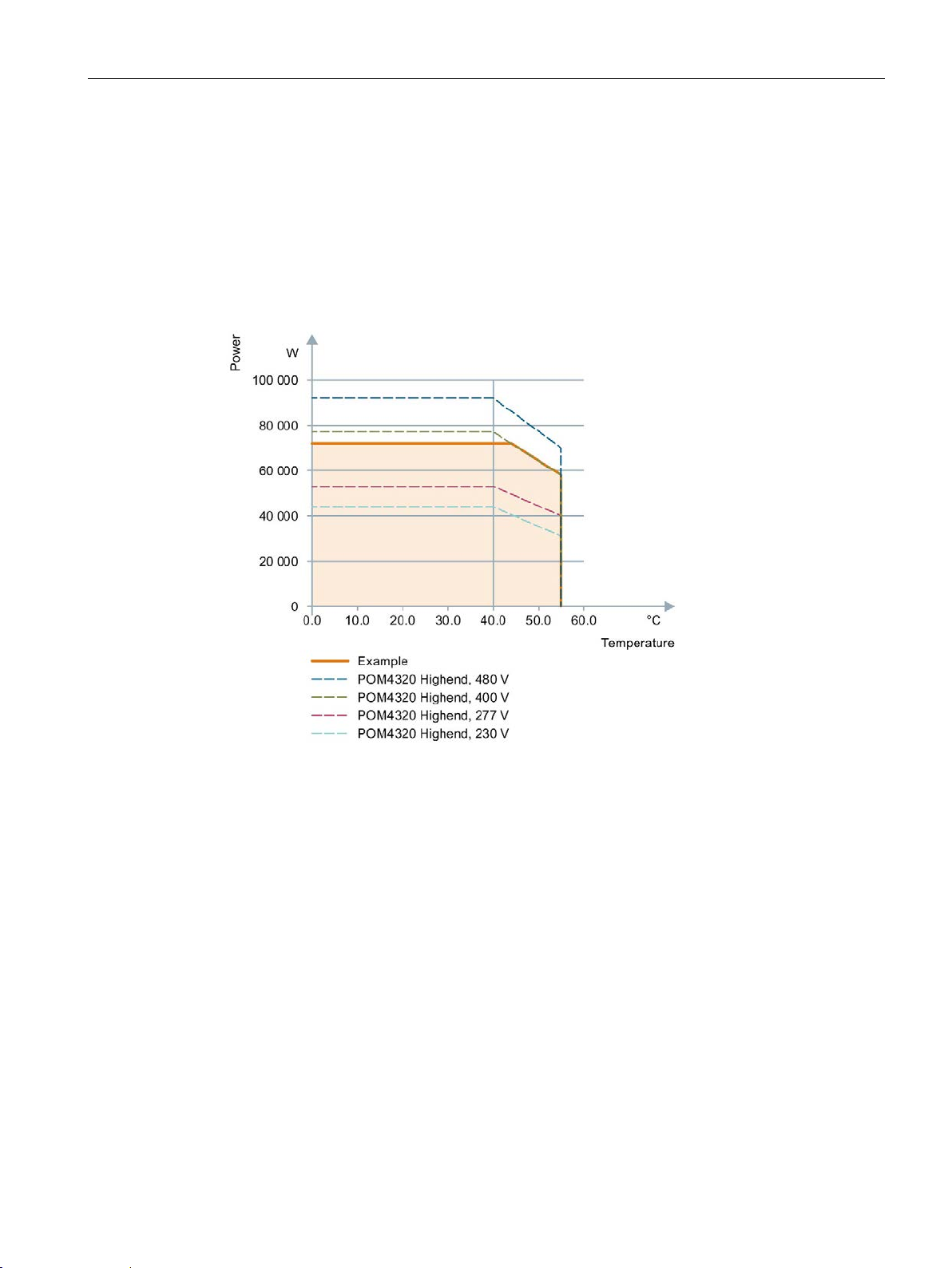
4.6 Power rating of the POM4320 Highend
4.6 Power rating of the POM4320 Highend
Power rating of the POM4320 Highend
Figure 4-3 Power rating of the POM4320 Highend depending on ambient temperature and line
voltage
SIPLUS HCS4300 PROFINET/PROFIBUS DP
36 Operating Instructions, 10/2019, A5E35452705A/005
Page 39
Application planning
4.6 Power rating of the POM4320 Highend
Example
You can find the power ratings for the example in section POM4320 Highend for wall
mounting (Page 40), section "Connecting between phase and phase (400/480 V), single
connection of outputs".
● Incoming fuse, internal, IEC
● Delta connection, open
● Total device performance at 400 V
SIPLUS HCS4300 PROFINET/PROFIBUS DP
Operating Instructions, 10/2019, A5E35452705A/005
37
Page 40

Application planning
Line voltage
400 V and 480 V
Incoming fuse
Internal, IEC
External, IEC
Not required, IEC
Delta connection, open
Total device performance at 400 V
57,600 W
76,800 W
–
Total device performance at 480 V
69,120 W
92,160 W
–
Delta connection, closed
Total device performance at 480 V
–
–
53,209 W
2-pin switching, phase – phase
Total device performance at 400 V
–
–
38,400 W
Total device performance at 480 V
–
–
46,080 W
4.7 POM4320 Highend power rating
4.7 POM4320 Highend power rating
4.7.1 POM4320 Highend for busbar adapter
Connection between phase and phase (400 V/480 V), single connection of outputs
Table 4- 1 POM4320 Highend for busbar adapter. connection between phase and phase
(400 V/480 V), single connection of outputs
Total device performance at 400 V – – 44,341 W
You can find block diagrams for the connection types in the section Connection between
phase and phase (400/480 V) (Page 62).
SIPLUS HCS4300 PROFINET/PROFIBUS DP
38 Operating Instructions, 10/2019, A5E35452705A/005
Page 41

Application planning
Line voltage
400 V and 480 V
Incoming fuse
Internal, IEC
External, IEC
Not required, IEC
Delta connection, open
Total device performance at 400 V
57,600 W
72,000 W
–
Delta connection, closed
Total device performance at 480 V
–
–
49,883 W
Line voltage
230 V and 277 V
Single connection of outputs,
IEC
Parallel connection of outputs,
IEC
Star connection, open
Total device performance at 230 V
44,160 W
41,400 W
Total device performance at 277 V
53,184 W
49,860 W
4.7 POM4320 Highend power rating
Connection between phase and phase (400 V/480 V), parallel connection of outputs
Table 4- 2 POM4320 Highend for busbar adapter. connection between phase and phase
(400 V/480 V), parallel connection of outputs
Total device performance at 480 V 69,120 W 86,400 W –
Total device performance at 400 V – – 41,569 W
You can find block diagrams for the connection types in the section Connection between
phase and phase (400/480 V) (Page 62).
Connection between phase and neutral conductor (230 V/277 V)
Table 4- 3 POM4320 Highend for busbar adapter, connection between phase and neutral conductor
(230 V/277 V)
You can find block diagrams for the connection types in the section Connection between
phase and neutral conductor (230/277 V) (Page 70).
SIPLUS HCS4300 PROFINET/PROFIBUS DP
Operating Instructions, 10/2019, A5E35452705A/005
39
Page 42

Application planning
Line voltage
400 V and 480 V
Incoming fuse
Internal,
IEC
Internal,
UL
External,
IEC
External,
UL
Not required,
IEC
Not required,
UL
Delta connection, open
400 V
W
480 V
W
Delta connection, closed
400 V
W
480 V
W
2-pin switching, phase – phase
400 V
W
480 V
W
4.7 POM4320 Highend power rating
4.7.2 POM4320 Highend for wall mounting
Connection between phase and phase (400 V/480 V), single connection of outputs
Table 4- 4 POM4320 Highend for wall mounting, connection between phase and phase
(400 V/480 V), single connection of outputs
Total device performance at
Total device performance at
Total device performance at
Total device performance at
Total device performance at
Total device performance at
72,000 W 62,400 W 76,800 W 72,000
86,400 W 74,880 W 92,160 W 86,400
– – – – 44,341 W 41,569
– – – – 53,209 W 49,883
– – – – 38,400 W 36,000
– – – – 46,080 W 43,200
– –
– –
You can find block diagrams for the connection types in the section Connection between
phase and phase (400/480 V) (Page 62).
SIPLUS HCS4300 PROFINET/PROFIBUS DP
40 Operating Instructions, 10/2019, A5E35452705A/005
Page 43

Application planning
Line voltage
400 V and 480 V
Incoming fuse
Internal,
IEC
Internal,
UL
External,
IEC
External,
UL
Not required,
IEC
Not required,
UL
Delta connection, open
400 V
W
480 V
W
Delta connection, closed
400 V
W
480 V
W
Line voltage
230 V and 277 V
Single-channel connection
Parallel connection, IEC
IEC
UL
IEC
UL
Star connection, open
230 V
277 V
4.7 POM4320 Highend power rating
Connection between phase and phase (400 V/480 V), parallel connection of outputs
Table 4- 5 POM4320 Highend for wall mounting, connection between phase and phase
(400 V/480 V), parallel connection of outputs
Total device performance at
Total device performance at
Total device performance at
Total device performance at
72,000 W 62,400 W 72,000 W 64,800
86,400 W 74,880 W 86,400 W 77,760
– – – – 41,569 W 37,412
– – – – 49,883 W 44,895
You can find block diagrams for the connection types in the section Connection between
phase and phase (400/480 V) (Page 62).
Connection between phase and neutral conductor (230 V/277 V)
Table 4- 6 POM4320 Highend for wall mounting, connection between phase and neutral conductor
(230 V/277 V)
Total device performance at
44,160 W 41,400 W 41,400 W 37,260 W
– –
– –
SIPLUS HCS4300 PROFINET/PROFIBUS DP
Operating Instructions, 10/2019, A5E35452705A/005
Total device performance at
You can find block diagrams for the connection types in the section Connection between
phase and neutral conductor (230/277 V) (Page 70).
53,184 W 49,860 W 49,860 W 44,874 W
41
Page 44

Application planning
4.7 POM4320 Highend power rating
SIPLUS HCS4300 PROFINET/PROFIBUS DP
42 Operating Instructions, 10/2019, A5E35452705A/005
Page 45

5
WARNING
Hazardous voltages on the heating control system
Can cause death, serious injury or damage to property
5.1 Requirements
Safety guidelines
Before starting installation or connection work on the HCS4300 heating control system, you
must switch off the heating control system and secure it from being switched on again.
SIPLUS HCS4300 PROFINET/PROFIBUS DP
Operating Instructions, 10/2019, A5E35452705A/005
43
Page 46

Installing/mounting
WARNING
Dangerous voltages on the busbar system
Can cause death, serious injury or damage to property
NOTICE
Clockwise rotating field
Note
Residual current protective device
If
circuit breaker of Type A is sufficient for the HCS4300.
Note
Due to the weight of the POM4320 we recommend
devices.
5.2 Installing the Power Output Module (POM)
5.2 Installing the Power Output Module (POM)
5.2.1 Busbar mounting
5.2.1.1 Preparations
Busbar system
The mains infeed for the power output module is connected via a 3-phase busbar system.
These include the following busbar systems:
● Siemens AG, SENTRON 60 mm
● Wöhner GmbH & Co. KG, 60 mm EQUES
Dangerous voltages can be present on the busbar system.
The busbar system must therefore be isolated and secured against reclosing before work
begins for mounting and connecting the HCS4300 heating control system.
When connecting the busbar system, make sure that the energy system is connected
clockwise.
a residual current protective device is provided for the busbar system, a residual current
mounting a busbar support after three
SIPLUS HCS4300 PROFINET/PROFIBUS DP
44 Operating Instructions, 10/2019, A5E35452705A/005
Page 47

Installing/mounting
POM busbar adapter
5.2 Installing the Power Output Module (POM)
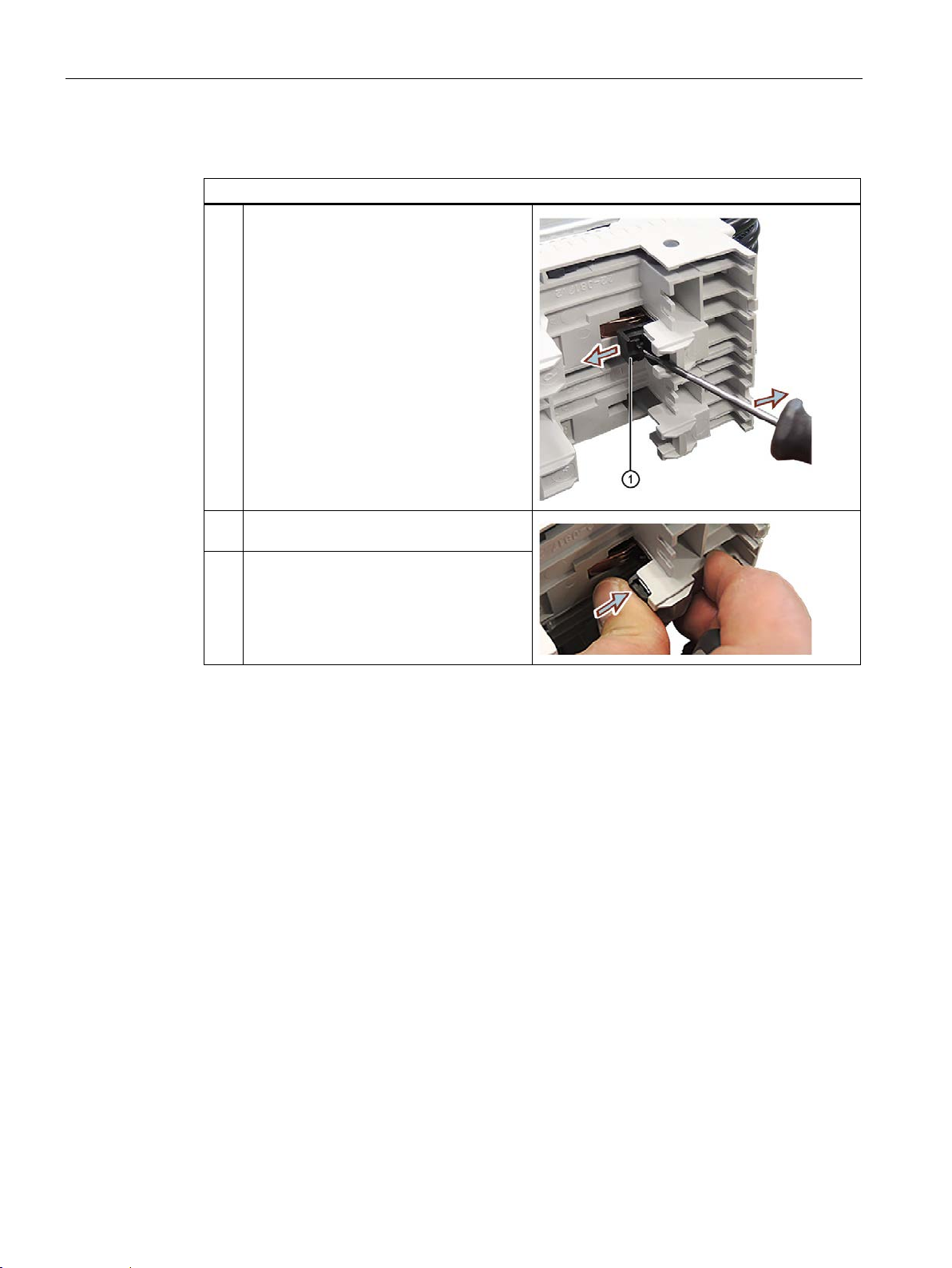
5.2.1.2 Adjusting the busbar adapter
Tool
You need a Phillips screwdriver, size 0.6 x 3.5 mm.
Adjusting the busbar adapter to the thickness of the busbar
The busbar adapter of the POM can be adjusted for the following busbar thicknesses:
● 5 mm (delivery state)
● 10 mm
On the busbar adapter of the POM, there are four fastening blocks, which you can use to
adjust the busbar adapter to the rail thickness. The following figure shows the position of the
fastening blocks.
Fastening block set to 5 mm
Fastening block set to 10 mm
SIPLUS HCS4300 PROFINET/PROFIBUS DP
Operating Instructions, 10/2019, A5E35452705A/005
45
Page 48
Installing/mounting
Steps
the rail thickness at 5 mm or 10 mm.
5.2 Installing the Power Output Module (POM)
Proceed as follows for each of the four fastening blocks:
1 Use the screwdriver to push out the fas-
tening block
2 Position the mounting block according to
①.
3 Push the mounting block inwards until it
clicks into place.
SIPLUS HCS4300 PROFINET/PROFIBUS DP
46 Operating Instructions, 10/2019, A5E35452705A/005
Page 49
Installing/mounting
Steps
The holder must protrude beyond the busbar adapter as shown in the figure.
②
③
5.2 Installing the Power Output Module (POM)
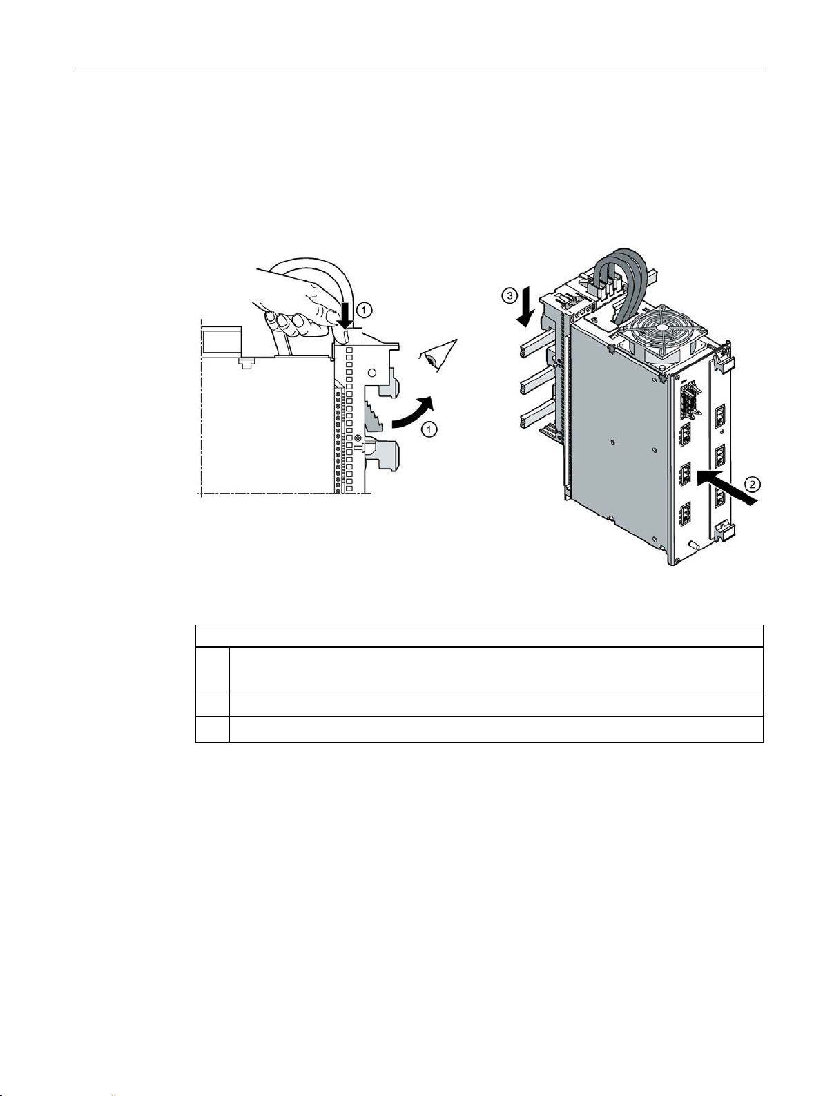
5.2.1.3 Mounting the POM (busbar adapter)
The mounting of the POM on the busbar is carried out without the need for tools via the
POM busbar adapter.
Installing the POM
Figure 5-1 Installing the POM
1
Press the button on the top of the busbar adapter
2
Place the busbar adapter on the busbar from above
3
Press on the busbar adapter from above until the busbar adapter engages
①.
.
.
SIPLUS HCS4300 PROFINET/PROFIBUS DP
Operating Instructions, 10/2019, A5E35452705A/005
47
Page 50
Installing/mounting
5.2 Installing the Power Output Module (POM)
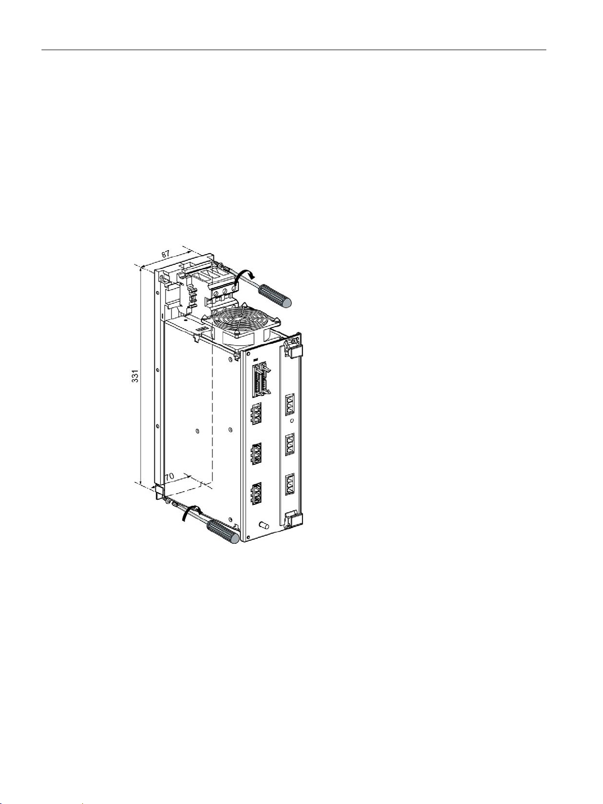
5.2.2 Panel mounting
5.2.2.1 POM mounting (panel mounting)
Installing the Power Output Modul (POM)
1. Predrill the holes in the rear panel for mounting.
The required hole spacing is shown in the diagram below.
2. Screw the POM into place on the rear panel with four screws M5.
Figure 5-2 POM4320: Position of the mounting holes
Minimum spacing
Natural convection must be possible above and below the device. A clearance of 100 mm
must be observed in both cases.
SIPLUS HCS4300 PROFINET/PROFIBUS DP
48 Operating Instructions, 10/2019, A5E35452705A/005
Page 51
Installing/mounting
Steps
①
②
5.3 Installing the Central Interface Module
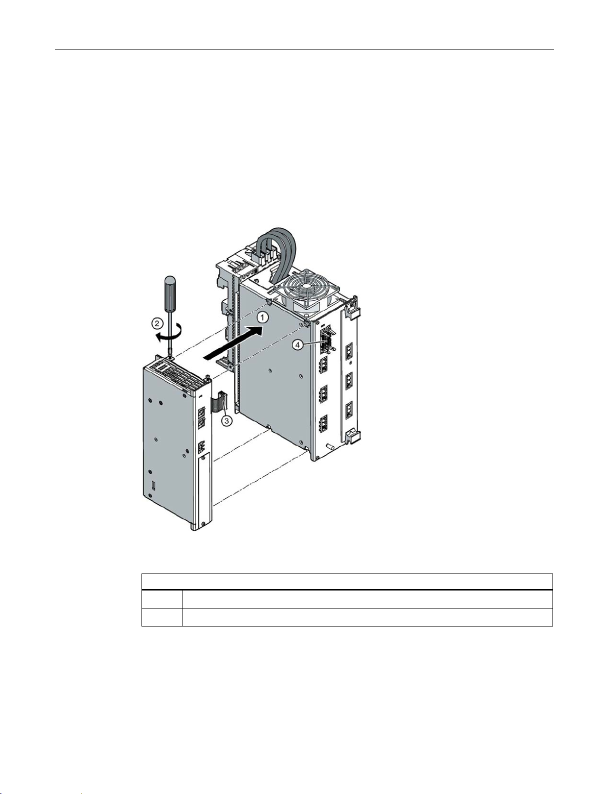
5.3 Installing the Central Interface Module
Tool
You will need a Torx T10 screwdriver.
Mounting the Central Interface Module (CIM)
The CIM is screwed directly onto the POM. The mounting procedure is described below:
Figure 5-3 Mounting the CIM
1
Plug the CIM into the POM by means of the four connecting lugs
2
Tighten the four screws
SIPLUS HCS4300 PROFINET/PROFIBUS DP
Operating Instructions, 10/2019, A5E35452705A/005
.
.
49
Page 52

Installing/mounting
5.4 Installing the EM4315 expansion module
5.4 Installing the EM4315 expansion module
Tool
You will need a Torx T10 screwdriver.
Installing the EM4315 expansion module
Proceed as described in Section Installing the Central Interface Module (Page 49).
SIPLUS HCS4300 PROFINET/PROFIBUS DP
50 Operating Instructions, 10/2019, A5E35452705A/005
Page 53

Installing/mounting
Note
The I/O module may only be inserted or removed when the power
Steps
1
Dismantling the blanking cover of the receptacle on the CIM
2
Insert the I/O module into the receptacle and push it in as far as it will go.
①
5.5 Installing the I/O module (PM)
5.5 Installing the I/O module (PM)
The CIM is equipped with a receptacle for one I/O module.
is off.
Tool
You will need a Torx T8 screwdriver.
Installing an I/O module
The steps for mounting an I/O module are described below:
Figure 5-4 Installing an I/O module
3
Secure module tightly with screws
SIPLUS HCS4300 PROFINET/PROFIBUS DP
Operating Instructions, 10/2019, A5E35452705A/005
51
Page 54

Installing/mounting
5.5 Installing the I/O module (PM)
SIPLUS HCS4300 PROFINET/PROFIBUS DP
52 Operating Instructions, 10/2019, A5E35452705A/005
Page 55

6
WARNING
Hazardous voltages from the mains power input or heating element feeder cables
Will cause death, serious injury or damage to property
WARNING
Electric shock hazard
Can cause death or serious injury
WARNING
Electric shock hazard
Can cause death or serious injury
The following apples to the UL version of the heating control system:
6.1 Safety instructions and guidelines
Safety instruction
Dangerous voltages might be present on mains from the supply and to heating elements.
Before work starts on connecting the HCS4300 heating control system, the mains and
heating element lines must be disconnected and secured against being switched on again.
• Voltages of more than 60 V can occur in the control cabinet. Suitable safety precautions
to prevent contact must therefore be taken before and during commissioning and
maintenance work.
• Before working on the heating control system or the connected components, ensure the
system is disconnected.
The mains supply to which the device is connected must have a circuit breaker or a fuse.
The circuit breaker or fuse must be easily accessible and clearly assigned to the device.
We recommend locating the circuit breaker or fuse near to the device. Take the maximum
current consumption of the heating control system into consideration when selecting the
circuit breaker or fuse.
• The mains supply to which the device is connected must have a circuit breaker
(according to UL489) or a fuse (UL-listed branch circuit fuse).
• Observe the SCCR rating on the rating plate. Only use the device in circuits limited
accordingly.
• Only use 60/75°C copper cables for the cabling.
SIPLUS HCS4300 PROFINET/PROFIBUS DP
Operating Instructions, 10/2019, A5E35452705A/005
53
Page 56
Wiring
WARNING
Electric shock hazard
Can cause death or serious injury
6.2 Connecting the protective conductor
Connection requirements
● The device is installed.
● The mains supply is disconnected at the installation location of the device and secured
against secured against reconnection.
● The mains voltage is secured by an easily accessible isolating mechanism. It is
recommended that the external isolating mechanism is located close to the device.
● The cables to be connected are not live.
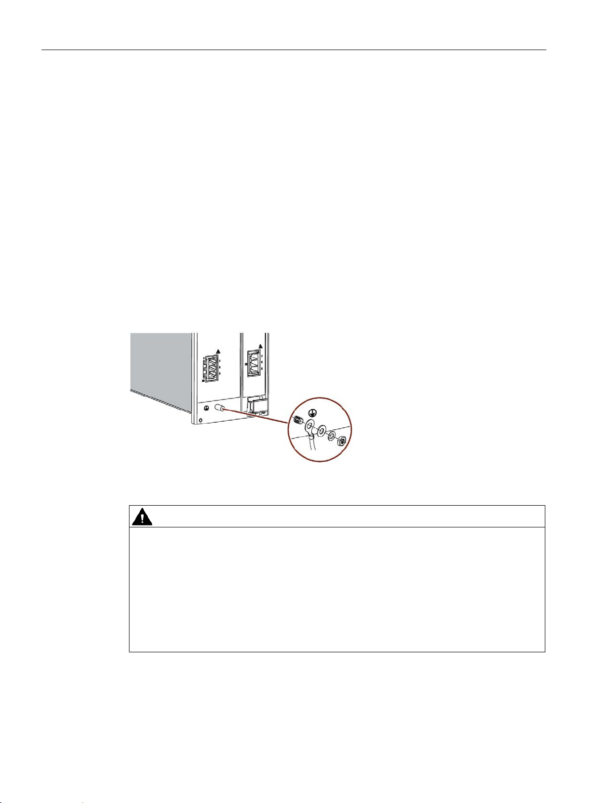
6.2 Connecting the protective conductor
Connecting the protective conductor
Connect the POM to the protective conductor (PE). An M6 threaded bolt ① is provided on
the front of the POM for connection of the protective conductor.
Figure 6-1 POM4320: Connecting the protective conductor
• The protective conductor must be connected to the threaded bolt indicated.
• The cross-section of the lead to the protective conductor must be at least 16 mm
• The cable lug used must have a tinned surface to guarantee corrosion protection.
• When connecting the protective conductor, the applicable national or local regulations
• Torque for protective conductor connection: 6 Nm
SIPLUS HCS4300 PROFINET/PROFIBUS DP
54 Operating Instructions, 10/2019, A5E35452705A/005
must be complied with.
2
.
Page 57
Wiring
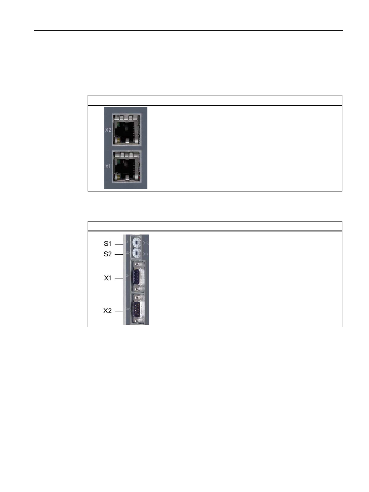
CIM PROFINET connection X1 / X2
CIM PROFIBUS connection X1
6.3 Connecting PROFINET and PROFIBUS fieldbus
6.3 Connecting PROFINET and PROFIBUS fieldbus
Connecting PROFINET
Connect X1 / X2 to the higher-level controller and/or the next
PROFINET device using an Ethernet cable according to the
PROFINET specification.
Use shielded Ethernet cables for this purpose.
Connecting PROFIBUS / setting PROFIBUS address
• The PROFIBUS address is assigned using the S1 / S2 address
selector switches. Addresses can be set from 0 to 99.
• Connect X1 to the higher-level controller and/or the next
PROFIBUS device via cable in accordance with the PROFIBUS
specification.
6.4 Connect 24 V DC power supply
Power is supplied to the Central Interface Module (CIM) and EM4315 expansion module via
an external 24 V DC supply. Use a power supply unit which conforms to IEC 60536,
protection class III (PELV). Power supply units from the SITOP product line are suitable, for
example.
SIPLUS HCS4300 PROFINET/PROFIBUS DP
Operating Instructions, 10/2019, A5E35452705A/005
The CIM and the EM4315 can both also supply up to 8 POM4320 or 6 POM4320 Highend
via the HCS system interface.
55
Page 58

Wiring
24 V connection CIM and EM4315
Connect the 24 V DV supply voltage to the device as follows:
+
+24 V DC
Note
An external lightning protection element should be connected upstream in the 24
supply line:
Dehn, Blitzductor BVT Type AD24, No. 918402 or equivalent.
When using other items, you must ensure that the model used is equivalent
lightning
The lightning protection module must be installed and used in accordance with the
manufacturer's specifications.
6.4 Connect 24 V DC power supply
Design of the 24 V DC power supply
You can determine the design of the 24 V DC power supply using the following calculation
formula:
Minimum power =
3 W + (number of POM4320 • 8 W) + (number of POM4320 Highends • 10 W) +
(number of I/O modules • 1 W)
Example:
Supply of an HCS4300 consisting of CIM4310 PROFINET with one I/O module and
6 connected POM4320.
The minimum power rating in accordance with the formula above is 52 W, i.e. the
power pack must be able to supply current of at least 2167 mA.
Connect 24 C DC supply voltage to CIM and EM4315
External lightning protector
protection manufacturer).
● The following interference immunity is obtained with a lightning protection component:
– 1.0 kV symmetrical with R
– 2.0 kV asymmetrical with R
- GND
V DC
(consult with
= 2 Ω; assessment criterion B
i
= 12 Ω; assessment criterion B
i
● Without lightning protection, the following interference immunity is obtained:
– 0.5 kV symmetrical with R
– 0.5 kV asymmetrical with R
= 2 Ω; assessment criterion B
i
= 12 Ω; assessment criterion B
i
SIPLUS HCS4300 PROFINET/PROFIBUS DP
56 Operating Instructions, 10/2019, A5E35452705A/005
Page 59

Wiring
Note
When using radiation sources with inrush current, we recommend using
Category AC
Note
The permissible tightening torque for the terminals of the devices for panel mounting is
3.5 Nm.
6.5 Connecting the heating elements and three-phase line supply
6.5 Connecting the heating elements and three-phase line supply
6.5.1 Connecting the three-phase line supply
In the case of POM4320 for busbar mounting, the network infeed is via a 3-phase busbar
system. See section Busbar mounting (Page 44).
With the POM4320 for panel mounting, three screw terminals, L1, L2 and L3, provide the
mains supply. The position of the screw terminals on the POM is shown in section Function
and design (Page 21).
3 contactors.
SIPLUS HCS4300 PROFINET/PROFIBUS DP
Operating Instructions, 10/2019, A5E35452705A/005
57
Page 60

Wiring
Note
The connected loads, e.g. heating elements, must not exceed the permissible line current of
≤ 83 A.
Location of the connections
Pin assignments X1 to X6
Power output 1 ... 3 outgoing
Power output 4 ... 6 outgoing
Power output 7 ... 9 outgoing
Power output 1 ... 3 incoming
Power output 4 ... 6 incoming
6.5 Connecting the heating elements and three-phase line supply
6.5.2 Connecting heating elements
Connecting heating elements to the POM4320
Heating elements are connected to the POM using six 3-pole connectors.
X1 3-pin connector for L1:
X2 3-pin connector for L2:
X3 3-pin connector for L3:
X4 3-pin connector for L2:
X5 3-pin connector for L3:
X6 3-pin connector for L1:
Power output 7 ... 9 incoming
SIPLUS HCS4300 PROFINET/PROFIBUS DP
58 Operating Instructions, 10/2019, A5E35452705A/005
Page 61

Wiring
Note
The
•
•
•
Location of the connections
Pin assignments X1 to X6
Power output 1 and 2, outgoing
Power output 3 and 4, outgoing
Power output 5 and 6, outgoing
Power output 1 and 2, incoming
Power output 3 and 4, incoming
6.5 Connecting the heating elements and three-phase line supply
Connecting heating elements to the POM4320 Highend
connected loads, e.g. heating elements, must not exceed the permissible line current:
Busbar mounting ≤ 83 A
Wall mounting ≤ 105 A
UL ≤ 90 A
X1 3-pin plug for L1:
X2 3-pin plug for L2:
X3 3-pin plug for L3:
X4 3-pin plug for L2:
X5 3-pin plug for L3:
X6 3-pin plug for L1:
Power output 5 and 6, incoming
See also
SIPLUS HCS4300 PROFINET/PROFIBUS DP
Operating Instructions, 10/2019, A5E35452705A/005
Function and design (Page 21)
Busbar mounting (Page 44)
59
Page 62
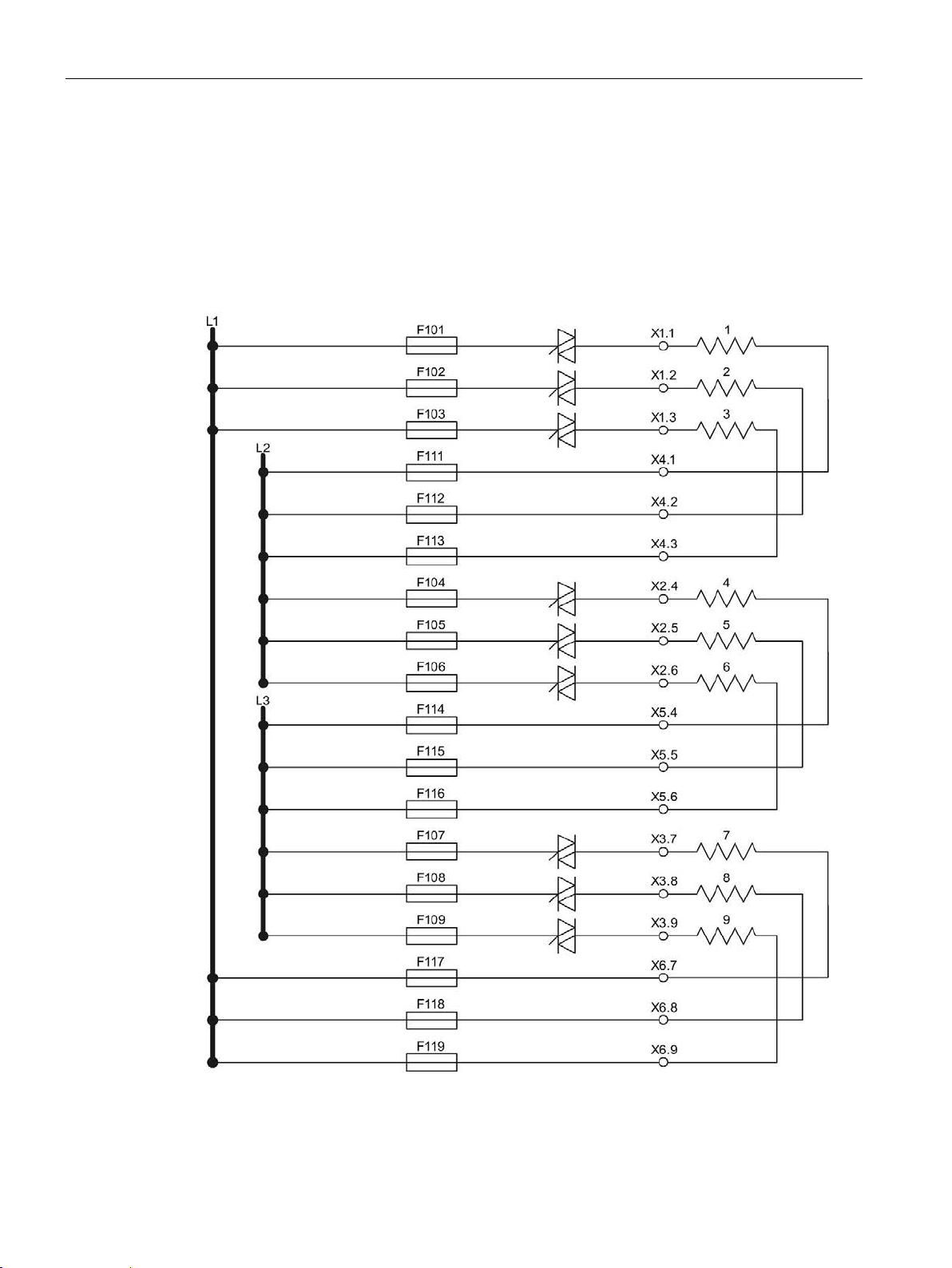
Wiring
6.6 Block diagram POM4320
6.6 Block diagram POM4320
Block diagram POM4320
The figure below shows the main connections between the HCS4300 heating controller and
the main supply and heating elements. The power outputs are protected internally with two
fuses per power output.
Figure 6-2 POM4320 power outputs
SIPLUS HCS4300 PROFINET/PROFIBUS DP
60 Operating Instructions, 10/2019, A5E35452705A/005
Page 63

Wiring
6.7 Block diagrams POM4320 Highend
6.7 Block diagrams POM4320 Highend
6.7.1 Overview of connection types
The following connection types are available for the POM4320 Highend:
Connection between phase and phase, 400/480 V
● Single connection of outputs, all fuses internal
● Single connection of outputs, external incoming fuses
● Single connection of outputs, 2-pin connection
● Single connection of outputs, closed delta
● Parallel connection of outputs with jumpers, 1 internal incoming fuse, ≤ 50 A
● Parallel connection of outputs with jumpers, 2 internal incoming fuses,
same nominal value for both fuses
● Parallel connection of outputs with jumpers, external incoming fuses
● Parallel connection of outputs with jumpers, closed delta
Connection between phase and neutral conductor, 230/277 V
● Single connection of outputs
● Parallel connection of outputs with jumpers
SIPLUS HCS4300 PROFINET/PROFIBUS DP
Operating Instructions, 10/2019, A5E35452705A/005
61
Page 64
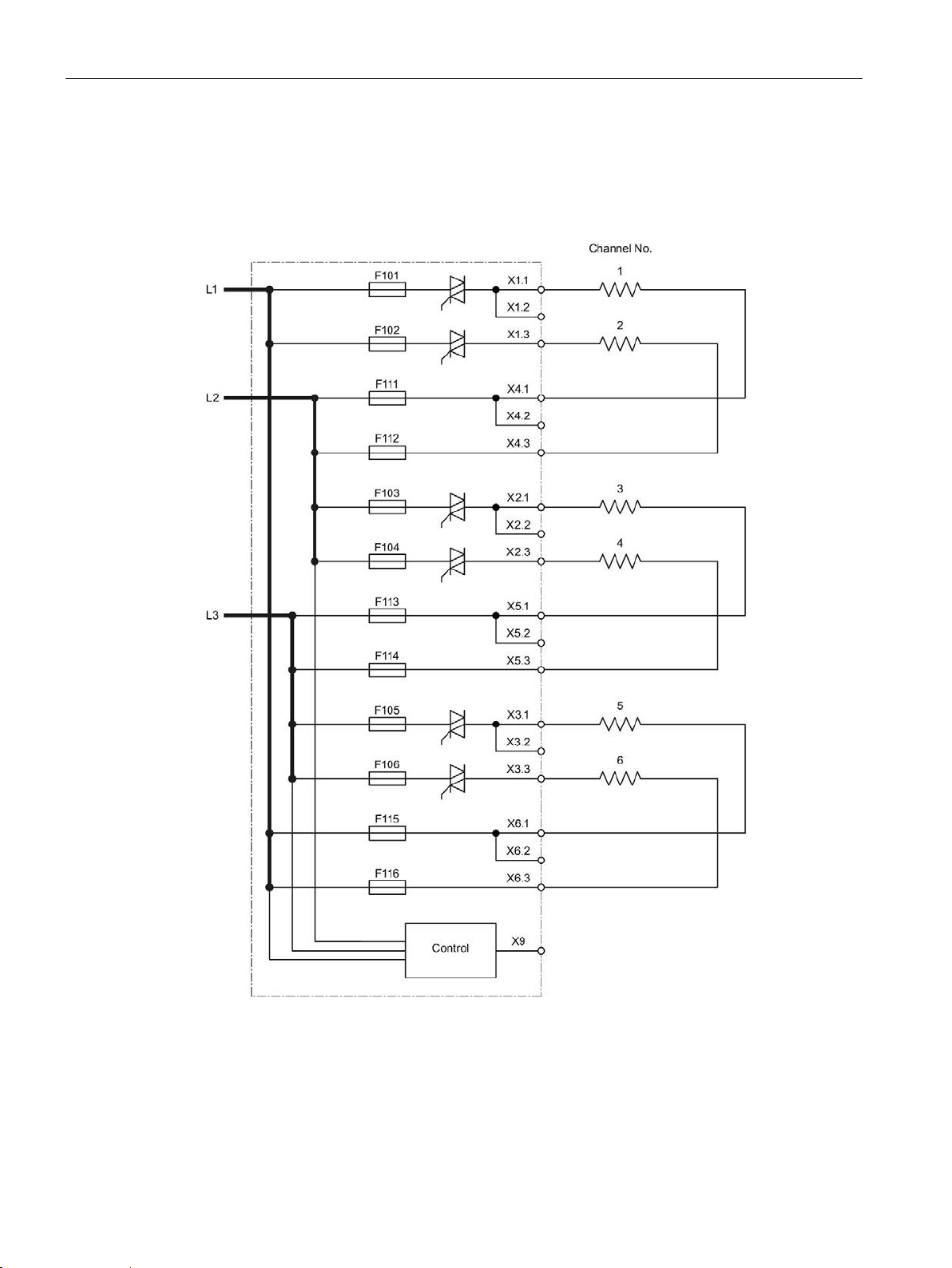
Wiring
6.7 Block diagrams POM4320 Highend
6.7.2 Connection between phase and phase (400/480 V)
Single connection of outputs, all fuses internal
Figure 6-3 POM4320 Highend – connection between phase and phase: Single connection of
outputs, all fuses internal
SIPLUS HCS4300 PROFINET/PROFIBUS DP
62 Operating Instructions, 10/2019, A5E35452705A/005
Page 65
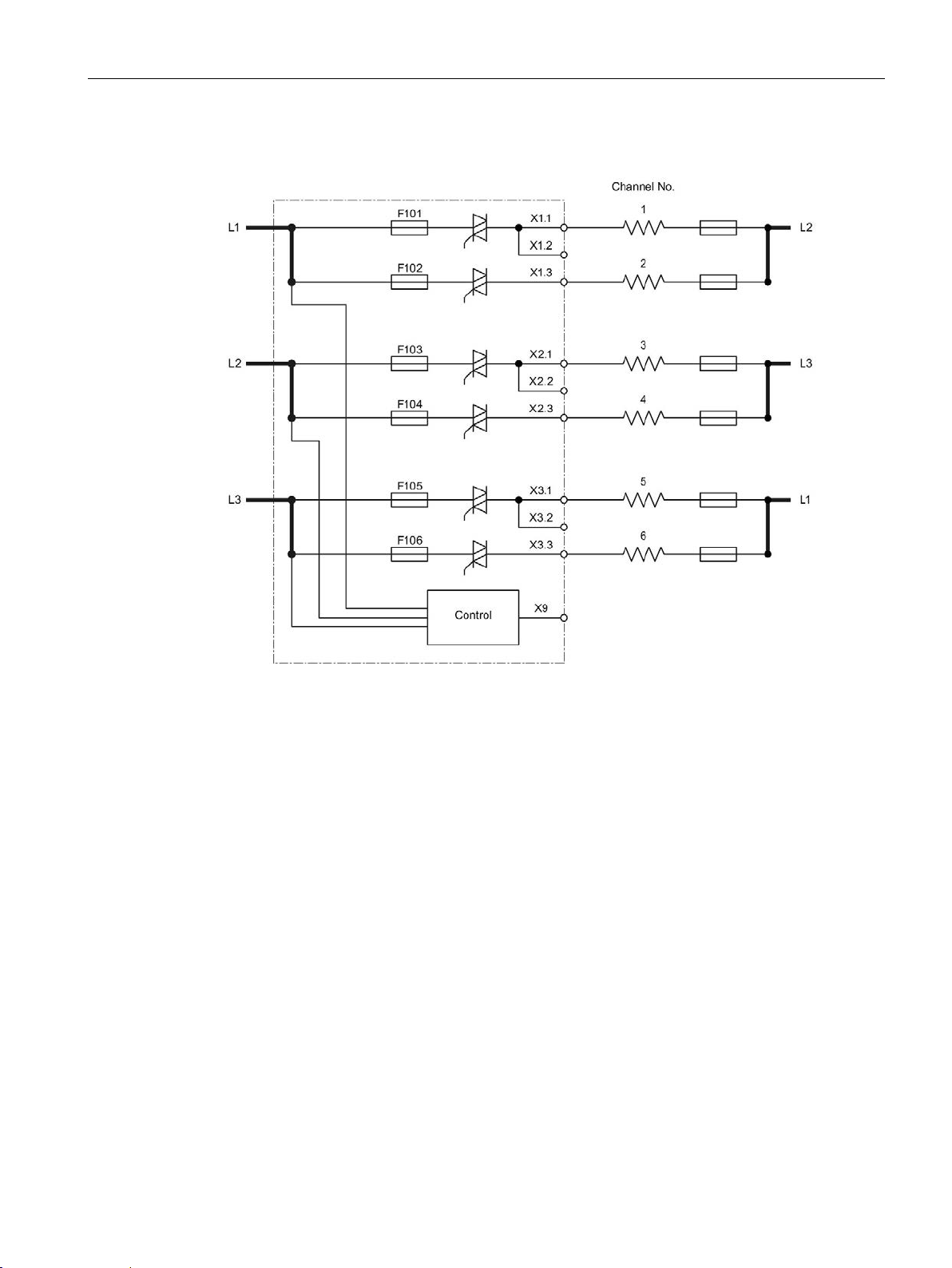
Wiring
6.7 Block diagrams POM4320 Highend
Single connection of outputs, external incoming fuses
Figure 6-4 POM4320 Highend – connection between phase and phase: Single connection of
outputs, external incoming fuses
SIPLUS HCS4300 PROFINET/PROFIBUS DP
Operating Instructions, 10/2019, A5E35452705A/005
63
Page 66
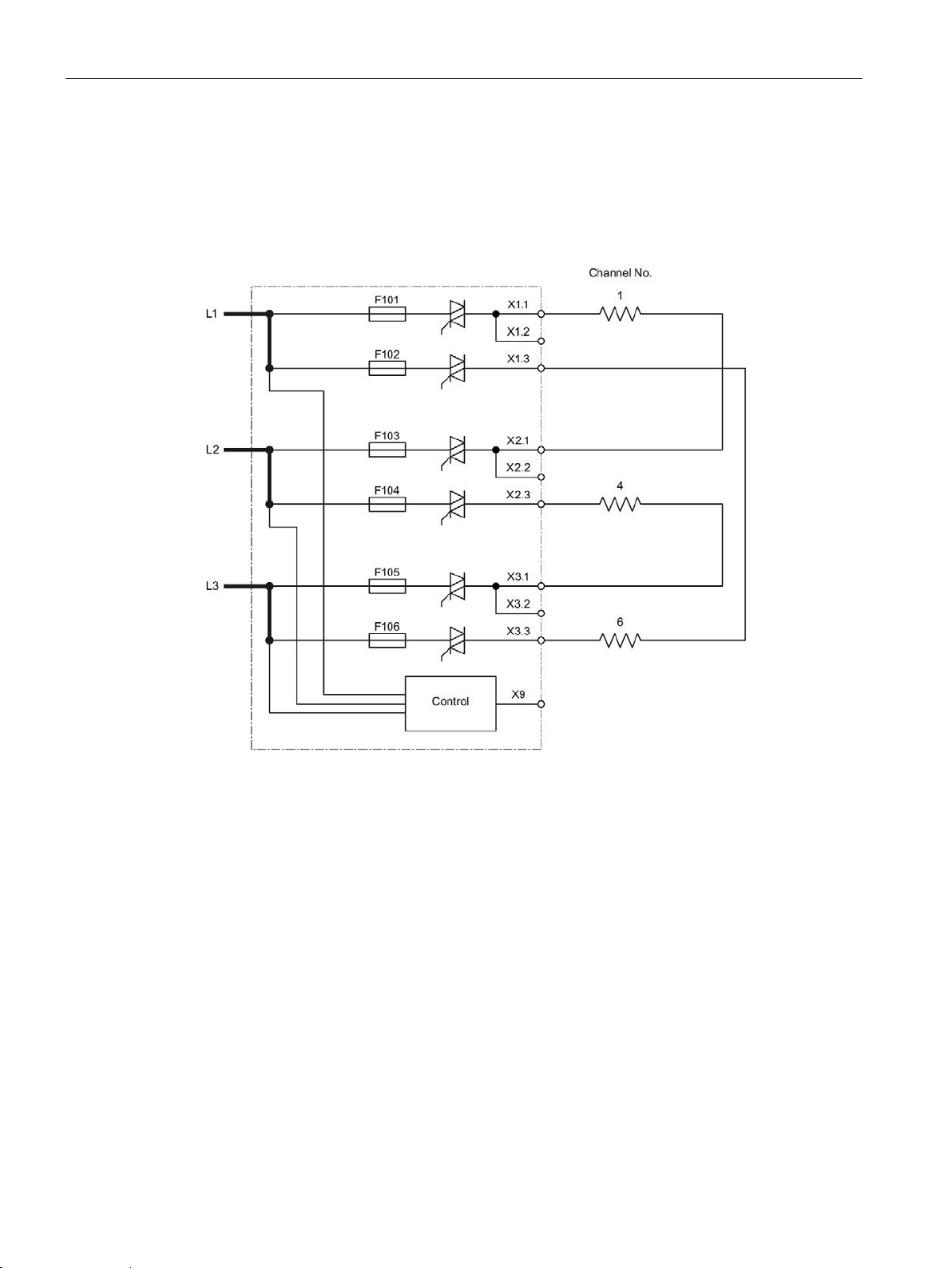
Wiring
6.7 Block diagrams POM4320 Highend
Single connection of outputs, 2-pin connection
For 2-pin switching of the outputs, the loads must be switched via the power semiconductors
from two channels. This has the following advantage: In case of a breakdown of the
depletion layer of one of the two main power semiconductors (short-circuit), operation is still
possible or the load can be turned off.
Figure 6-5 POM4320 Highend – connection between phase and phase: Single connection of
outputs, 2-pin connection
SIPLUS HCS4300 PROFINET/PROFIBUS DP
64 Operating Instructions, 10/2019, A5E35452705A/005
Page 67
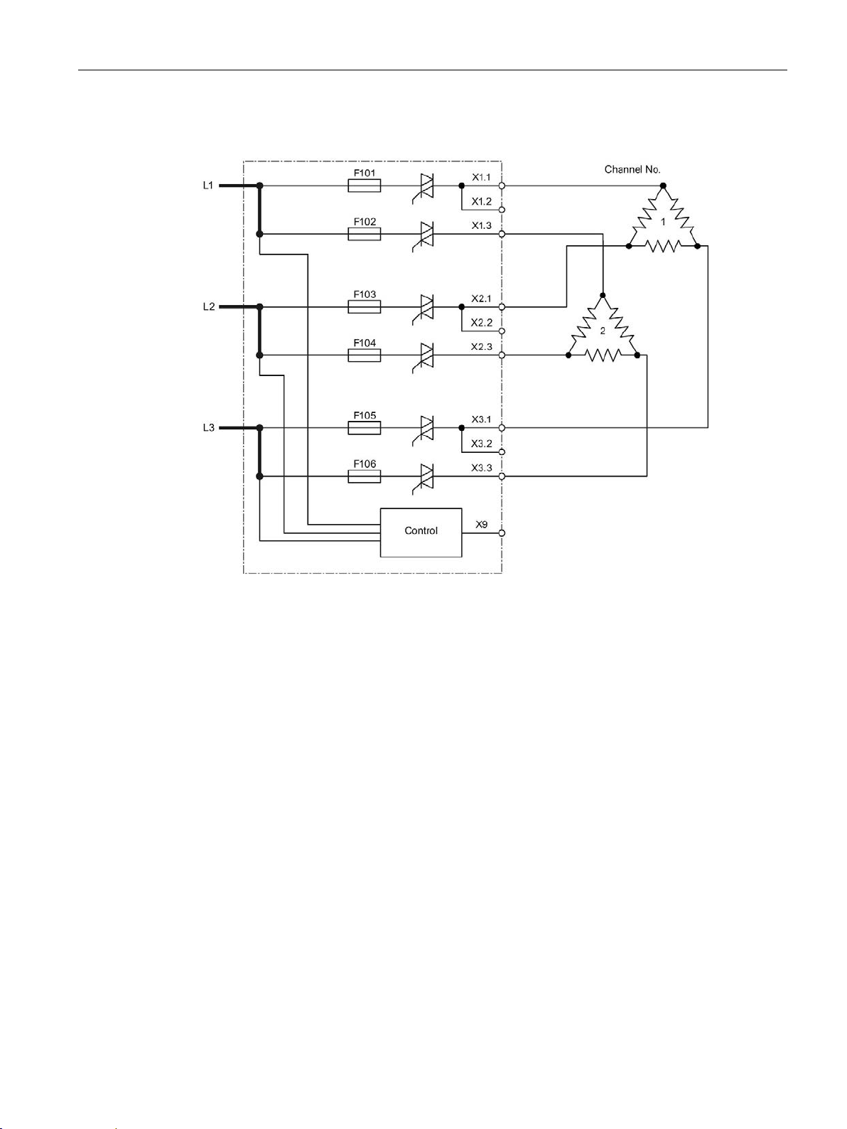
Wiring
6.7 Block diagrams POM4320 Highend
Single connection of outputs, closed delta
Figure 6-6 POM4320 Highend – connection between phase and phase: Single connection of
outputs, closed delta
SIPLUS HCS4300 PROFINET/PROFIBUS DP
Operating Instructions, 10/2019, A5E35452705A/005
65
Page 68
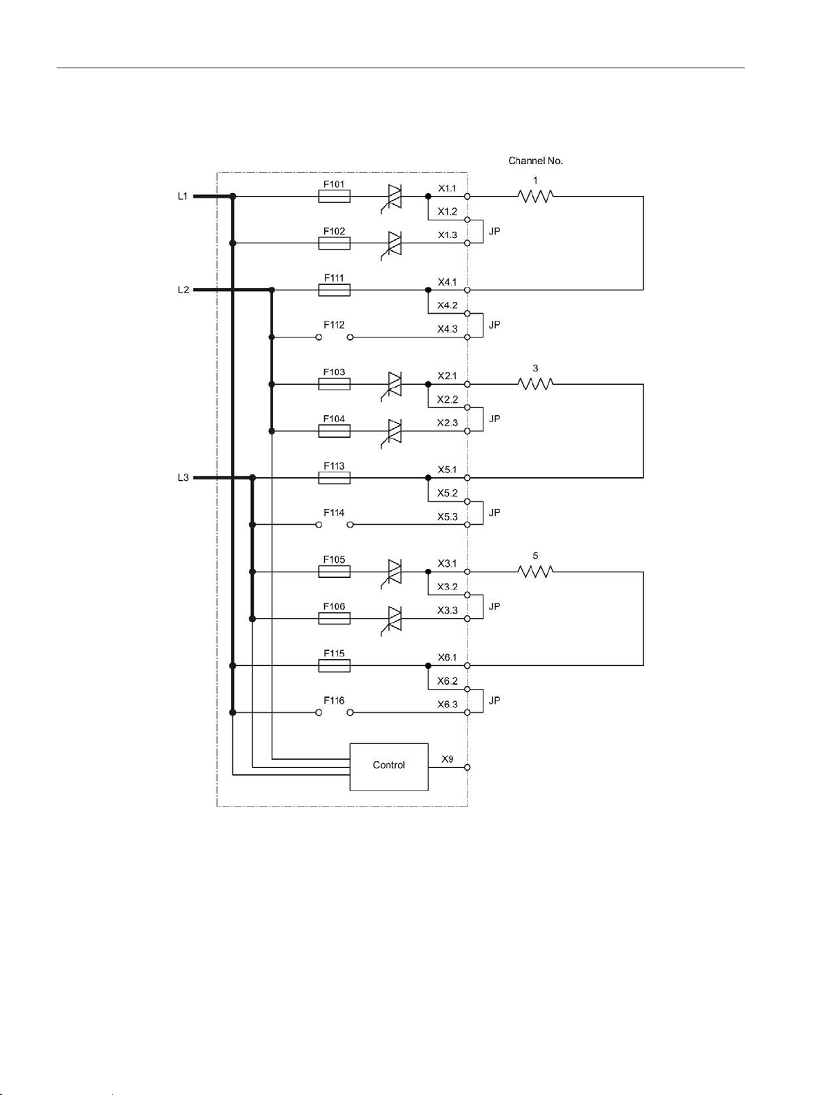
Wiring
JP
Jumper plug for parallel connection
6.7 Block diagrams POM4320 Highend
Parallel connection of outputs with jumpers, 1 internal incoming fuse, ≤ 50 A
Figure 6-7 POM4320 Highend – connection between phase and phase: Parallel connection of
SIPLUS HCS4300 PROFINET/PROFIBUS DP
66 Operating Instructions, 10/2019, A5E35452705A/005
outputs with jumpers, 1 internal incoming fuse, ≤ 50 A
Page 69
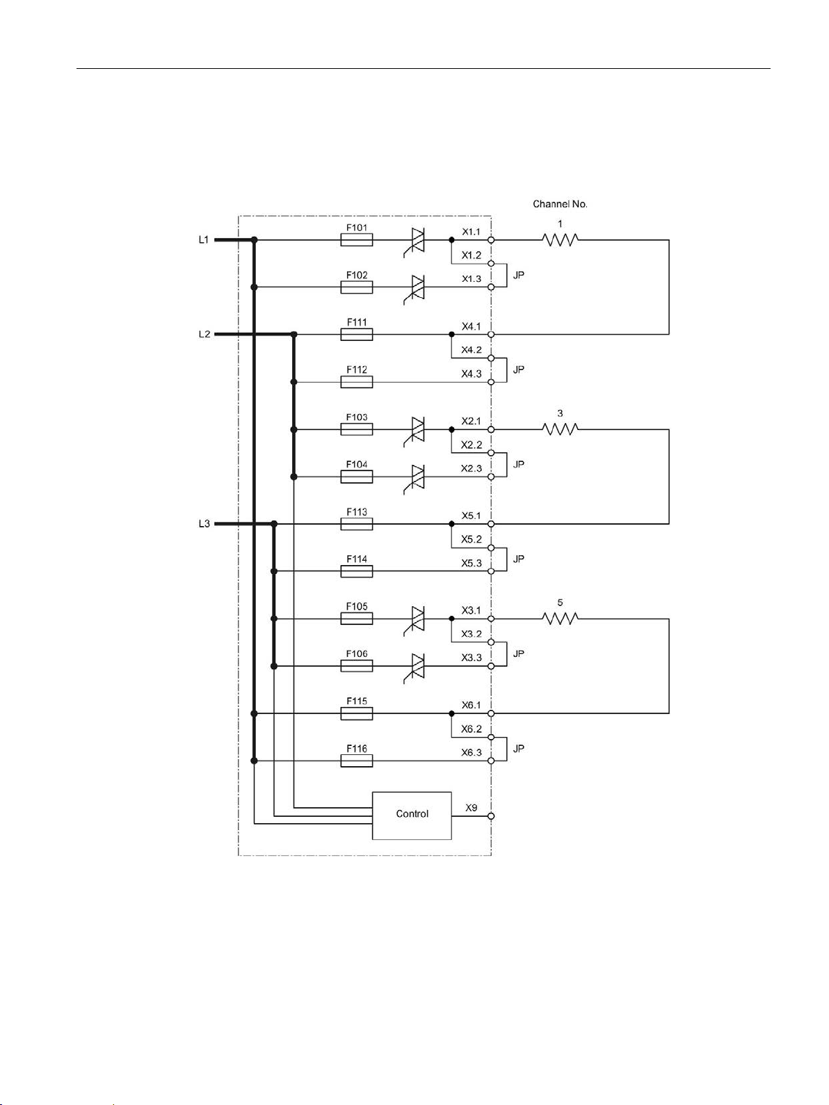
Wiring
JP
Jumper plug for parallel connection
6.7 Block diagrams POM4320 Highend
Parallel connection of outputs with jumpers, 2 internal incoming fuses, same nominal value
for both fuses
Two 32 A fuses are permissible for the following block diagram.
SIPLUS HCS4300 PROFINET/PROFIBUS DP
Operating Instructions, 10/2019, A5E35452705A/005
Figure 6-8 POM4320 Highend – connection between phase and phase: Parallel connection of
outputs with jumpers, 2 internal incoming fuses, same nominal value for both fuses
67
Page 70
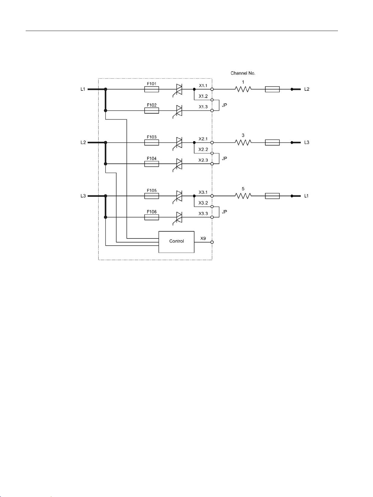
Wiring
JP
Jumper plug for parallel connection
6.7 Block diagrams POM4320 Highend
Parallel connection of outputs with jumpers, external incoming fuses
Figure 6-9 POM4320 Highend – connection between phase and phase: Parallel connection of
outputs with jumpers, external incoming fuses
SIPLUS HCS4300 PROFINET/PROFIBUS DP
68 Operating Instructions, 10/2019, A5E35452705A/005
Page 71
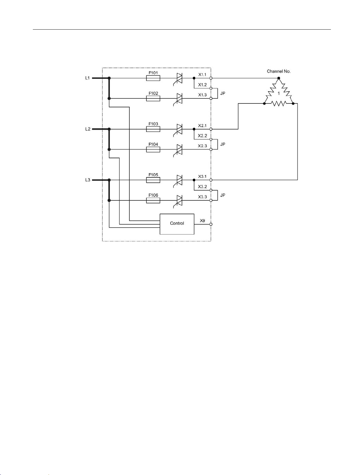
Wiring
JP
Jumper plug for parallel connection
6.7 Block diagrams POM4320 Highend
Parallel connection of outputs with jumpers, closed delta
Figure 6-10 POM4320 Highend – connection between phase and phase: Parallel connection of
outputs with jumpers, closed delta
SIPLUS HCS4300 PROFINET/PROFIBUS DP
Operating Instructions, 10/2019, A5E35452705A/005
69
Page 72
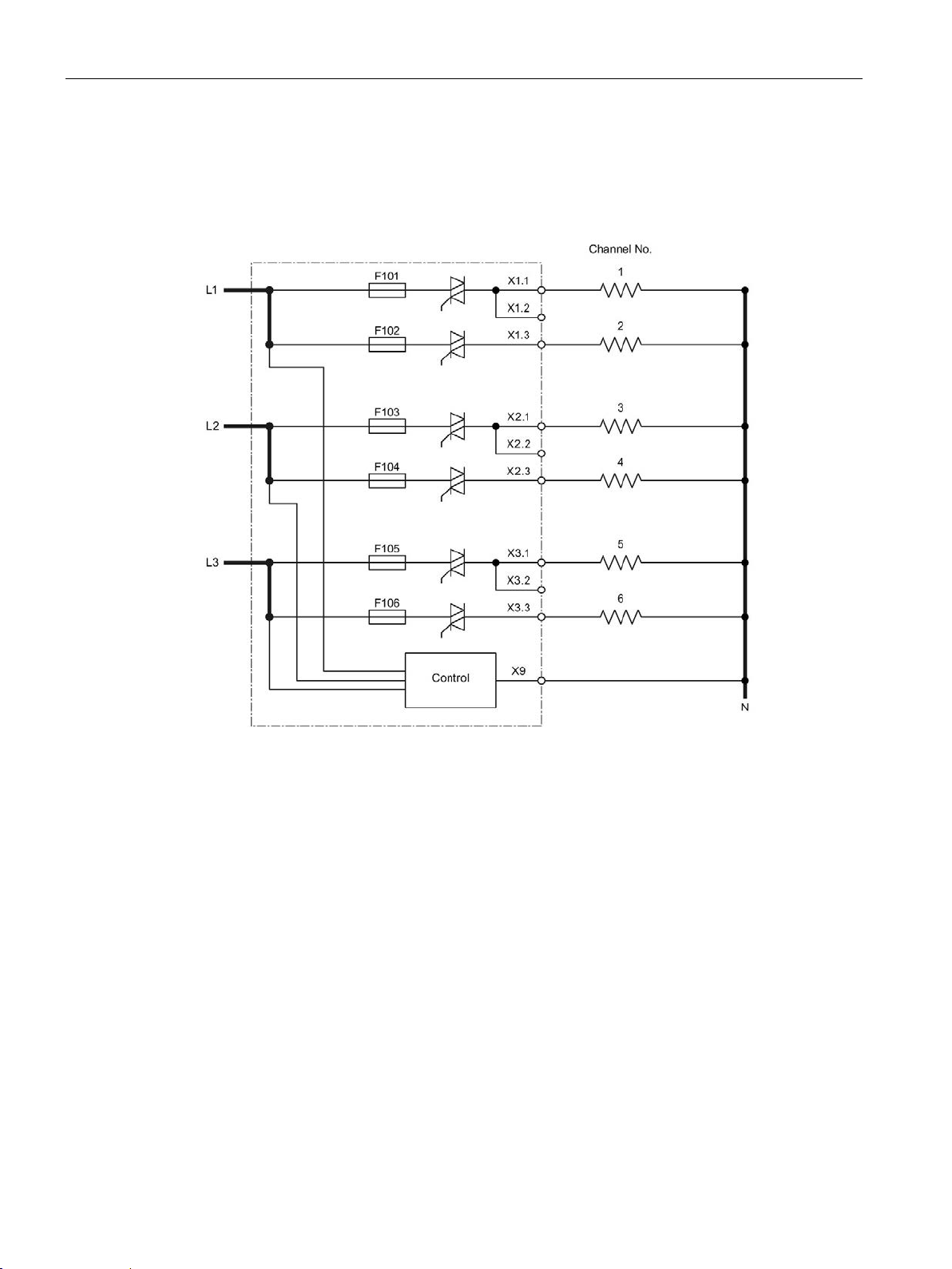
Wiring
6.7 Block diagrams POM4320 Highend
6.7.3 Connection between phase and neutral conductor (230/277 V)
Single connection of outputs
Figure 6-11 POM4320 - connection between phase and neutral conductor Single connection of
outputs
SIPLUS HCS4300 PROFINET/PROFIBUS DP
70 Operating Instructions, 10/2019, A5E35452705A/005
Page 73
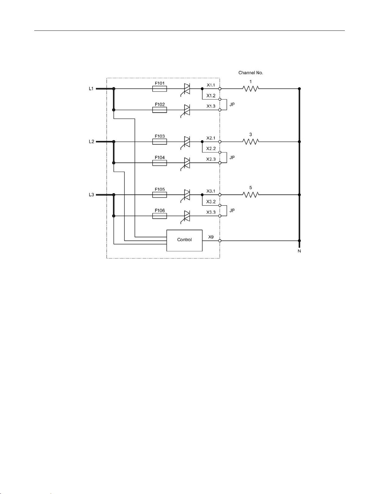
Wiring
JP
Jumper plug for parallel connection
6.7 Block diagrams POM4320 Highend
Parallel connection of outputs with jumpers
Figure 6-12 POM4320 Highend – connection between phase and neutral conductor: Parallel
connection of outputs with jumpers
SIPLUS HCS4300 PROFINET/PROFIBUS DP
Operating Instructions, 10/2019, A5E35452705A/005
71
Page 74

Wiring
System interface CIM or EM4315 to POM
Note
The last bus connector remains open at the last POM.
6.8 Connecting system interfaces
6.8 Connecting system interfaces
Connecting system interfaces (front)
Attach the connecting cable between the CIM /
EM4315 and POM
8 POM4320 or 6 POM4320 Highend at a CIM /
EM4315.
Additional POMs can be connected with a ribbon
cable to the preceding POM.
①. You can operate up to
SIPLUS HCS4300 PROFINET/PROFIBUS DP
72 Operating Instructions, 10/2019, A5E35452705A/005
Page 75

Cable length of connecting cable
Note
The total length of all connecting cables per segment at the system interface of the CIM4310
and EM4315 must be ≤ 3 m.
The following figure shows cable lengths which correspond to the permissible
total length ≤ 3 m:
100 + 250 + 100 + 250 + 100 + 1000 ≤ 3000
Wiring
6.8 Connecting system interfaces
SIPLUS HCS4300 PROFINET/PROFIBUS DP
Operating Instructions, 10/2019, A5E35452705A/005
73
Page 76

Wiring
Note
The connection cables are to be shielded if longer than 30
6.9 Connecting I/O modules
6.9 Connecting I/O modules
6.9.1 PM4000 DI/DO
Connecting the digital inputs/outputs
The connection is made by means of two 18-pin plug connectors of the PM4000 DI/DO.
Figure 6-13 PM4000 DI/DO pin assignment
SIPLUS HCS4300 PROFINET/PROFIBUS DP
74 Operating Instructions, 10/2019, A5E35452705A/005
m.
Page 77

Wiring
Note
The maximum permission current of the connector is 8 A.
Pin
Assignment
Pin
1
GND
Digital output 1
2
3
GND
Digital output 2
4 5 GND
Digital output 3
6
7
GND
Digital output 4
8
9
GND
Digital output 5
10
11
GND
Digital output 6
12
13
GND
Digital output 7
14
15
GND
Digital output 8
16
17
GND
P24
18
Pin
Assignment
Pin
1
GND
Digital input/output 9
2
3
GND
Digital input/output 10
4
5
GND
Digital input/output 11
6 7 GND
Digital input/output 12
8
11
GND
Digital input/output 14
12
15
GND
Digital input/output 16
16
17
GND
P24
18
6.9 Connecting I/O modules
For each connector, one pin each is available for the connection or the reintroduction of the
24 V supply voltage and the 0 V supply voltage. All 24 V and GND pins of both connectors
are respectively connected so that, with consideration to the maximum current, a loopingthrough of the supply voltage is possible (daisy chain).
X1: Digital outputs:
18-pin connector with spring-loaded connection and interlock. The mating connectors are
included in the scope of supply.
X2: Digital inputs / outputs
18-pin connector with spring-loaded connection and interlock. The mating connectors are
included in the scope of supply.
9 GND Digital input/output 13 10
13 GND Digital input/output 15 14
SIPLUS HCS4300 PROFINET/PROFIBUS DP
Operating Instructions, 10/2019, A5E35452705A/005
75
Page 78

Wiring
WARNING
Voltage hazards
Danger to life
6.9 Connecting I/O modules
6.9.2 PM4000 U/I
Connecting line measurement inputs
Connecting to mains power is done via the 8-pin plug-in connector X1 of the PM4000 U/I.
Connecting to mains voltage is done via the 6-pin plug-in connector X2 of the PM4000 U/I.
Before working on the heating control system or the connected components, ensure the
system is disconnected.
SIPLUS HCS4300 PROFINET/PROFIBUS DP
76 Operating Instructions, 10/2019, A5E35452705A/005
Figure 6-14 Line measurement inputs, pin assignment
Page 79

Wiring
Pin
Assignment
Pin
1
I1 -
I1 +
2
3
I2 -
I2 +
4
5
I3 -
I3 +
6
Note
The connection cable for the current measurement must not be longer than 30
Pin
Assignment
1
Reserved
2
Phase 1
3
Phase 2
4
Phase 3
5
Neutral conductor
6
Reserved
6.9 Connecting I/O modules
X1: Current measurement
8-pin connector with spring-loaded connection and interlock. The mating connectors are
included in the scope of supply.
7 Reserved Reserved 8
m.
X2: Voltage measurement
6-pin connector with spring-loaded connection and interlock. The mating connectors are
included in the scope of supply.
SIPLUS HCS4300 PROFINET/PROFIBUS DP
Operating Instructions, 10/2019, A5E35452705A/005
77
Page 80
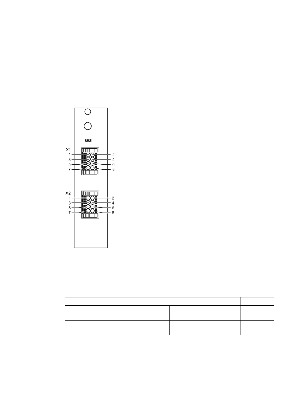
Wiring
Pin
Assignment
Pin
1
Analog channel 1 -
Analog channel 1 +
2
3
Analog channel 2 -
Analog channel 2 +
4
5
Analog channel 3 -
Analog channel 3 +
6
7
Analog channel 4 -
Analog channel 4 +
8
6.9 Connecting I/O modules
6.9.3 PM4000 Temperature
Connecting the measurement inputs
The analog inputs 0...20 mA are connected by means of the 8-pin plug connector X1 of the
PM4000 Temperature.
The measurement inputs for temperature are connected by means of the 8-pin plug
connector X2 of the PM4000 Temperature.
Figure 6-15 PM4000 Temperature pin assignment
X1: Four analog inputs 0 ... 20 mA
8-pin connector with spring-loaded connection. The mating connectors are included in the
scope of supply.
SIPLUS HCS4300 PROFINET/PROFIBUS DP
78 Operating Instructions, 10/2019, A5E35452705A/005
Page 81
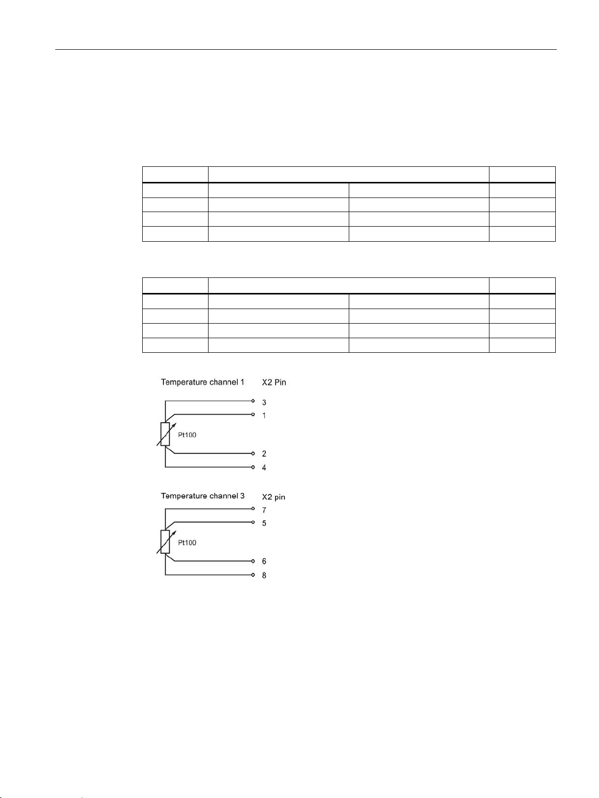
Wiring
Pin
Assignment
Pin
1
Temperature channel 1 -
Temperature channel 1 +
2
3
Temperature channel 2 -
Temperature channel 2 +
4
5
Temperature channel 3 -
Temperature channel 3 +
6
Pin
Assignment
Pin
1
Temperature channel 1 U-
Temperature channel 1 U+
2
3
Temperature channel 1 I-
Temperature channel 1 I+
4
5
Temperature channel 3 U-
Temperature channel 3 U+
6
7
Temperature channel 3 I-
Temperature channel 3 I+
8
6.9 Connecting I/O modules
X2: Temperature measuring inputs
8-pin connector with spring-loaded connection. The mating connectors are included in the
scope of supply.
2-wire measurement
7 Temperature channel 4 - Temperature channel 4 + 8
4-wire measurement
SIPLUS HCS4300 PROFINET/PROFIBUS DP
Operating Instructions, 10/2019, A5E35452705A/005
Figure 6-16 Wiring of the measuring inputs to X2 for 4-wire measurement using example of Pt100
79
Page 82

Wiring
6.9 Connecting I/O modules
SIPLUS HCS4300 PROFINET/PROFIBUS DP
80 Operating Instructions, 10/2019, A5E35452705A/005
Page 83

7
7.1 Requirements
Before commissioning starts, the system components must be installed and wired up.
The following is necessary:
● A SIMATIC S7 CPU / SIMOTION with PROFINET/PROFIBUS interface
● A SIPLUS HCS4300 heating control system, comprising one central interface module
(CIM) and at least one power output module (POM).
7.2 Commissioning
Procedure
1. Switch on the 24 V DC power supply.
2. Switch on the three-phase power supply for the heating control system.
The components CIM, POM and PM, if installed, of the heating control system start up.
Observe the operating mode indicators (see section Process and system messages,
error handling (Page 145)).
The heating control system is in operation.
SIPLUS HCS4300 PROFINET/PROFIBUS DP
Operating Instructions, 10/2019, A5E35452705A/005
81
Page 84

Commissioning
Voltage
Protective conductor current
400 V, 50 Hz
<1.1 mA
7.3 Insulation test
7.3 Insulation test
Because of the protective impedances in the device, the isolation resistance of a device of
each phase to ground with an open load is around 124 kΩ and around 70 kΩ with connected
heating loads. These values must be taken into account during the insulation test on the
system.
If there are several devices in one circuit, you must allow for the parallel connection of the
impedances. If necessary, you must remove the device from the circuit before
the insulation test.
Protective conductor current
Due to the protective impedances, the following protective conductor current flows under
normal operating conditions:
480 V, 60 Hz <1.4 mA
SIPLUS HCS4300 PROFINET/PROFIBUS DP
82 Operating Instructions, 10/2019, A5E35452705A/005
Page 85

8
8.1 Integrating the HCS4300 into the PROFINET configuration
Procedure with SIMATIC S7
If the hardware catalog of your configuration software does not feature the HCS4300 yet, it
can be integrated by installing an HSP. An HSP is available for TIA Portal and can be
downloaded from the Siemens Service&Support area
(http://www.siemens.com/automation/service&support /).
Procedure with non-Siemens controllers
For PROFINET configuration you will need the language-specific GSDML file. The GSDML
file must be installed in the configuration software.
The GSDML file "GSDML-V2.34-Siemens-002A-HCS4300from the Siemens Service&Support area
(http://www.siemens.com/automation/service&support).
If a non-Siemens PROFINET controller is used, install the GSDML file as described in the
manufacturer's instructions.
yyyymmdd
" can be downloaded
8.2 Integrating the HCS4300 into the PROFIBUS configuration
Procedure with SIMATIC S7
If the hardware catalog of your configuration software does not feature the HCS4300 yet, it
can be integrated by installing the GSD file. The file is available in German (SIEM81C5.gsg)
and English (SIEM81C5.gse) and can be downloaded from the Siemens Service&Support
area (http://www.siemens.com/automation/service&support /).
Procedure with non-Siemens controllers
You will need the language-specific GSD file for PROFIBUS configuration. The
SIEM81C5.gsx files can be downloaded from the Siemens Service&Support area
(http://www.siemens.com/automation/service&support /).
If a non-Siemens PROFIBUS controller is used, install the GSD file as described in the
manufacturer's instructions.
SIPLUS HCS4300 PROFINET/PROFIBUS DP
Operating Instructions, 10/2019, A5E35452705A/005
83
Page 86

Configuring/Programming
CIM
POM 1
POM 2
POM 3
...
Last POM
(PROFINET IO)
Subslot 1.1
Subslot 1.2
Note
The device configuration in the project engineering must match the actual configuration of
the HCS.
Otherwise the system cannot start up. Exception: Using the configuration control (see
Configuration control
8.3 Device/hardware configuration in the TIA Portal
8.3 Device/hardware configuration in the TIA Portal
8.3.1 PROFINET device configuration
Device configuration
In the case of PROFINET, the structure of the hardware is mirrored in the TIA device
configuration:
Slot number 0
1 CIM head
I/O module
2 3 4 n
The configuration rules are as follows:
CIM
Slot 0 represents the PROFINET connection with the two ports. The CIM provides a slot for
an I/O module. The CIM module and the CIM I/O module are assigned to slot 1 and are
designed as submodules. If an I/O module is not used, subslot 1.2 remains empty.
POM
A maximum of 24 POMs can be operated on one CIM.
(Page 93)).
SIPLUS HCS4300 PROFINET/PROFIBUS DP
84 Operating Instructions, 10/2019, A5E35452705A/005
Page 87

Configuring/Programming
Slot
CIM
PM
POM 1
POM 2
POM 3
…
Last
POM
Number 1 2 3 4 5 …
n
Note
The device configuration in the project engineering must match the actual configuration of
the HCS. Otherwise the system cannot start up.
8.3 Device/hardware configuration in the TIA Portal
8.3.2 PROFIBUS device configuration
Device configuration
In the case of PROFIBUS, the structure of the hardware in the device configuration is as
follows:
The device configuration rules are as follows:
● CIM
The CIM module includes the PROFIBUS-connection and is permanently present in
slot 1.
● PM
The CIM I/O module is present in slot 2. If no I/O module PM is used, an empty space
must be configured here.
● POM
A maximum of 24 POMs can be operated on one CIM.
Restrictions for PROFIBUS connection
The following functions are not available or only available with limited functionality with a
PROFIBUS connection:
● Configuration control is not available
● Phase control cannot be configured for operation of a POM4320
● Operation of a POM4320 Highend is not possible
SIPLUS HCS4300 PROFINET/PROFIBUS DP
Operating Instructions, 10/2019, A5E35452705A/005
85
Page 88

Configuring/Programming
Description
Value range
compensation
Description
Value range
8.3 Device/hardware configuration in the TIA Portal
8.3.3 Configuration parameters
8.3.3.1 CIM / POM configuration parameters
The configuration parameters are directly assigned to the respective module and are set
during device configuration. The transfer is performed automatically upon start-up and during
re-parameterization.
Configuration parameters CIM
Rated voltage for line voltage
Configuration control
Configuration parameters POM4320
Control mode
(Set once per POM)
Response to errors
(setting per channel)
• 360 V to 520 V
• No (default)
• Yes
• Half-wave control (default)
• Half-wave control with soft start variant 1
• Half-wave control with soft start variant 2
• Half-wave control with soft start variant 3
• Phase control
• Phase control with soft start variant 1
• Phase control with soft start variant 2
• Phase control with soft start variant 3
• Channel substitute value 0 (default)
• Channel value retained
SIPLUS HCS4300 PROFINET/PROFIBUS DP
86 Operating Instructions, 10/2019, A5E35452705A/005
Page 89

Configuring/Programming
Description
Value range
(setting once per POM)
8.3 Device/hardware configuration in the TIA Portal
Configuration parameters POM4320 Highend
Control type
(setting once per POM)
Connection type
(setting once per POM)
Soft start for each channel switch-on
operation
Enable output control
(setting once per POM)
Parallel connection of channels
Enable fault current monitoring
(setting once per POM)
Threshold for fault current monitoring
Response to faults
(setting per channel)
Parallel connection of loads
(setting per channel)
• Half-wave control (default)
• Half-wave control with soft start variant 1
• Half-wave control with soft start variant 2
• Half-wave control with soft start variant 3
• Half-wave control with adaptive soft start
• Phase control
• Phase control with soft start variant 1
• Phase control with soft start variant 2
• Phase control with soft start variant 3
• Phase control with adaptive soft start
• Connection between phase and phase (internal fuse)
(default)
• Connection between phase and phase (external fuse)
• Connection between phase and neutral conductor
• 2-pin connection between phase and phase
• Connection between phase and phase (closed delta)
• No (default)
• Yes
• No (default)
• Yes
• No (default)
• All channels
• One channel (1-2)
• One channel (3-4)
• One channel (5-6)
• Two channels (1-2, 3-4)
• Two channels (1-2, 5-6)
• Two channels (3-4, 5-6)
• No (default)
• Yes
• 400 mA to 2,000 mA
• Channel substitute value 0 (default)
• Channel value retained
• No (default)
• Yes
SIPLUS HCS4300 PROFINET/PROFIBUS DP
Operating Instructions, 10/2019, A5E35452705A/005
87
Page 90

Configuring/Programming
Description
Value range
total power (setting per channel)
Note
Scaling the total power for parallel connection of loads
•
•
8.3 Device/hardware configuration in the TIA Portal
Total power rating (setting per channel)
Maximum permitted deviation from
• 500 W to 28,800 W
• 100 W to 8,000 W
For a connection of the load between phase and neutral conductor, the power ratings to
be configured must be scaled to 230 V.
For a connection of the load between phase and phase, the power ratings to be
configured must be scaled to 400 V.
Calculation example for interconnection of phase - neutral conductor
Scaling:
P
= P
scaled
Load with U
P
= 1500 W * (230 V/240 V)2
scaled
P
= 1378 W
scaled
* (230 V/U
load
= 240 V; P
rated
load
)2
rated
= 1500 W
Calculation example for interconnection of phase - phase
Scaling:
P
= P
scaled
Load with U
P
= 6000 W * (400 V/480 V)2
scaled
P
= 4167 W
scaled
* (400 V/U
load
= 480 V; P
rated
load
)2
rated
= 6000 W
SIPLUS HCS4300 PROFINET/PROFIBUS DP
88 Operating Instructions, 10/2019, A5E35452705A/005
Page 91

Configuring/Programming
Description
Value range
1)
temperature channel 2 / 4.
8.3 Device/hardware configuration in the TIA Portal
8.3.3.2 Configuration parameters for I/O modules
The configuration parameters are directly assigned to the respective I/O modules and are set
during device configuration. They are transferred on start-up and during re-parameterization.
Configuration parameters PM4000 temperature
Analog channel 1 measuring range
…
Analog channel 4 measuring range
Temperature channel 1 sensor type
Temperature channel 3 sensor type
Temperature channel 2 sensor type
Temperature channel 4 sensor type
Compensation procedure
• Not connected (default)
• 0 mA to 20 mA
• 4 mA to 20 mA (open-circuit detection)
• None (default)
• Pt 100
• Pt 100 (four-wire)
• Pt 1000
• Pt 1000 (four-wire)
• Type J thermocouple
• Type K thermocouple
• Type L thermocouple
• None (default)
1)
• Pt 100
• Pt 1000
1)
• Type J thermocouple
• Type K thermocouple
• Type L thermocouple
• No compensation (default)
• Internal sensor
• External value
SIPLUS HCS4300 PROFINET/PROFIBUS DP
Operating Instructions, 10/2019, A5E35452705A/005
When setting Pt 100/1000 (four-wire) for temperature channel 1 / 3, "none" must be selected for
89
Page 92

Configuring/Programming
Description
Value range
Digital channel 16
be closed or controlled with "1".
Description
Value range
8.3 Device/hardware configuration in the TIA Portal
Configuration parameters PM4000 DI/DO
Digital channel 9
…
Output 1 Response to errors
…
Output 16 Response to errors
Alarm at wire break
Alarm on absence of
24 V power supply
Configuration parameters PM4000 U/I
Type of voltage connection
Type of current converter
• Input (default)
• Output
• Shutdown (default)
• Keep last value
• Switching on
• No (default)
• Yes
Note:
If power outage monitoring is enabled, unused outputs must
• No (default)
• Yes
• Star (default)
• Delta
• None
• None (default)
• 1 A
• 5 A
SIPLUS HCS4300 PROFINET/PROFIBUS DP
90 Operating Instructions, 10/2019, A5E35452705A/005
Page 93

Configuring/Programming
Note
There is no example project or
Note
Requirement
This function requires the use of the example application or at least the data structure of the
example a
8.4 Software tools for commissioning support
8.4 Software tools for commissioning support
8.4.1 Overview of tools for commissioning support
Listed below are the tools that can provide support with configuration and commissioning.
SIMATIC WinCC
A library in TIA Portal for SIMATIC WinCC is available for integration in an HMI system. This
library contains a specific number of channels and fields; setpoints can be assigned and
actual values can be displayed.
Example application
An example project and a block library for TIA Portal are available for the SIMATIC S7-1500
automation systems to support commissioning of the heating control system.
HTML pages (SIMATIC S7)
SIMATIC controllers with PROFINET interface (e.g. S7-1500) have an integrated web server
that contains web pages for displaying diagnostics data. This web server can be accessed
via a standard web browser.
This supports scanning of the firmware version, diagnostics buffer, tag tables and module
status, as well as monitoring of communication links and displaying the topology of the plant.
In the event of a fault, the user can view the exact error message in plain text in the detail
view for the module.
block library for STEP 7 Classic.
pplication.
SIPLUS HCS4300 PROFINET/PROFIBUS DP
Operating Instructions, 10/2019, A5E35452705A/005
91
Page 94

Configuring/Programming
8.4 Software tools for commissioning support
PRONETA
SIEMENS PRONETA PC-based software tool that is provided free-of-charge, which
simplifies the commissioning of PROFINET systems by performing the following tasks:
● Topology overview that automatically scans PROFINET and displays all connected
components. This overview can be exported in the form of a device list. You have the
option of "Initializing" the components and performing other simple configuration tasks, as
well as comparing the actual configuration with a required configuration.
● IO check to quickly test the wiring of a plant and the module configuration of the
components. By reading and writing the inputs and outputs, PRONETA makes sure that
the distributed I/O devices with their sensors and actuators are correctly wired.
PRONETA can create test profile templates and store test logs to document the test
results.
● All tasks can be performed even before a CPU is integrated into the network. Moreover,
since no other engineering tools or hardware are required, PRONETA enables fast and
convenient checking of a plant configuration at an early stage. You can find additional
information on the PRONETA here
(http://support.automation.siemens.com/WW/view/de/67460624).
SIPLUS HCS4300 PROFINET/PROFIBUS DP
92 Operating Instructions, 10/2019, A5E35452705A/005
Page 95

Configuring/Programming
8.5 Configuration control
8.5 Configuration control
8.5.1 Configuration control
Introduction
Configuration control (option handling) is used to operate various standard machine
configuration levels in one project without changing the configuration or the user program.
Operating principle of configuration control
You can use the configuration control to operate different expansion levels of a series
machine with a single configuration of the HCS.
● A station master is configured in a project (maximum configuration). The station master
comprises all modules needed for all possible plant parts of a modular standard machine.
● The project's user program provides for several station options for various standard
machine configuration levels as well as selection of a station option. For example, a
station option uses only some of the modules of the station master.
Advantages
● The standard machine manufacturer selects a station option for a configuration of the
standard machine. To do this, the project need not be modified, and it is not necessary to
load a modified configuration.
Using a custom control data record, you inform the HCS which modules in a station option
are missing or are located in a different slot as compared to the station master. The
configuration control does not have an impact on the parameter assignment of the modules.
The following figure shows 3 expansion levels of a heating control system with the
associated station options.
Figure 8-1 Configuration control
● Simple project execution and commissioning by using a single STEP 7 project for all
station options.
● Easy handling during maintenance, versioning and upgrades:
● Savings potential in the creation, commissioning and the documentation for standard
machines.
SIPLUS HCS4300 PROFINET/PROFIBUS DP
Operating Instructions, 10/2019, A5E35452705A/005
93
Page 96

Configuring/Programming
Step
Procedure
See section
1
Enable configuration control in STEP 7
Configuring (Page 94)
2
Create control data record
Control data record (Page 95)
program of the CPU (Page 98)
Modules
Possible slots
Comment
the configuration control.
the configuration control, but instead controls it.
dled here as a slot 1).
POM
2 to 25
Without empty slot directly after the CIM.
8.5 Configuration control
Procedure
To set up the configuration control, follow these steps:
3 Transfer control data record Transferring the control data record in the startup
8.5.2 Configuring
Requirements
● Configuration control only works with PROFINET.
● One CIM4310 PROFINET version V2.1 and higher
Required steps
When configuring the CIM4320 in STEP 7 (TIA Portal), enable the "Configuration control on"
parameter.
8.5.3 Control
8.5.3.1 Slot assignment
Slot assignment
The following table shows the possible slots for the various modules:
Table 8- 1 Slot assignment
CIM PN 0 The PN connection of the CIM is not an element of
CIM 1.1 The header of the CIM (subslot) is not an element of
PM 1.2 As a sub-slot part of the configuration control (han-
SIPLUS HCS4300 PROFINET/PROFIBUS DP
94 Operating Instructions, 10/2019, A5E35452705A/005
Page 97

Configuring/Programming
8.5 Configuration control
8.5.3.2 Control data record
Operating principle
You define a control data record 196 V1.0, which includes a slot assignment for the
configuration control of an HSC. The control data record can also be read back.
The control data record is only processed with configured configuration control; otherwise it
is rejected.
Rules
Observe the following rules:
● The entry for slot 1 only identifies the PM (see also Table 8-1 Slot assignment (Page 94)).
● All modules up to the maximum possible configuration of the HCS must be registered in
control data record.
● The entries up to at least the last slot of the station master must be contained in the
control data record. Entries beyond the last slot must be pre-assigned with "Module not
available".
● Multiple configured slots must not be assigned to the same actual slot. In other words,
each station option slot can be present only once in the control data record.
● Gaps are not permitted.
● Moving modules is not allowed.
SIPLUS HCS4300 PROFINET/PROFIBUS DP
Operating Instructions, 10/2019, A5E35452705A/005
95
Page 98

Configuring/Programming
Byte
Element
Code
Explanation
maximum slot
2
Version
1
master
station option
Control element
master
station option
...
...
...
...
...
...
...
8.5 Configuration control
Control data record
The table below shows the structure of a control data record with explanations of the
individual elements. The control data record can also be read back.
Table 8- 2 Structure of the simplified control data record V1.0
0 Block length 4 +
1 Block ID 196
3 Version 0
4 Slot 1 of the station
5 Slot 2 of the station
28 Slot 25 of station mas-
ter
Slot assignment in the
Slot assignment in the
Slot assignment
Header
Contains the information on which
module is inserted in which slot.
The value that you need to enter in the
corresponding byte depends on the
following rule:
• If the module is included in the
station option, enter the slot number of the module from the station
master.
• If the module does not exist in the
station option, enter 0.
SIPLUS HCS4300 PROFINET/PROFIBUS DP
96 Operating Instructions, 10/2019, A5E35452705A/005
Page 99

Configuring/Programming
Byte
Element
Code
Explanation
number of slots x 2
1
Block ID
197
2
2
3
0
4
Slot 1 status
0/1
5
Reserved
0
6
Slot 2 status
0/1
7
Reserved
0
… … …
53
Status of slot 25
0/1
* Not possible if the slot is marked as not available.
8.5 Configuration control
8.5.3.3 Feedback data record
Operating principle
The feedback data record informs you about the accuracy of the module assignment and
gives you the option of detecting assignment errors in the control data record. The feedback
data record is mapped via a separate data record 197 V2.0. The feedback data record is
only processed with configured configuration control; otherwise it is rejected.
Rules
Observe the following rules:
● The feedback data record refers to the configured station configuration and always
includes the maximum configuration limits, which is 25 modules.
● Partial reading of the feedback data record is not possible.
● As long as a control data record is not sent, it is assumed that no modules are inserted
(DS197 has status "0").
Feedback data record
Table 8- 3 Feedback data record
0 Block length 4 +
54 Reserved 0
Header
Version
Status = 1:
• Module from station master is in-
serted in the station option
• Slot is marked as not available in
the control data record
Status = 0:
• Module pulled
• Incorrect module inserted in the
station option*
SIPLUS HCS4300 PROFINET/PROFIBUS DP
Operating Instructions, 10/2019, A5E35452705A/005
97
Page 100

Configuring/Programming
ID
Hardware identifier
INDEX
Data record number: 196 (decimal)
For the structure of the control data record, see table (Page 95).
Error code
Meaning
80B1H
Invalid length; the length information in data record 196 is not correct.
80B5H
Configuration control parameters not assigned.
transferred in the startup program.
8.5 Configuration control
8.5.3.4 Transferring control data record in the startup program of the CPU
Required steps
Transfer the created control data record 196 to the CIM using the WRREC (Write data
record) instruction.
To verify the configuration, the feedback data record 197 can be queried by the CIM with the
RDREC instruction (read data).
Parameters of the instruction WRREC
Below, you will find explanations of individual parameters of the WRREC instruction which
you must supply with specific values in the configuration control context. You can find
additional information on the WRREC instruction in the STEP 7 online help.
RECORD Control data record to be transferred.
In case of an error, the WRREC instruction returns the following error messages through the
STATUS block parameter:
Table 8- 4 Error message WRREC
80E2H Data record was transferred in the wrong OB context. The data record must be
80B8H Parameter error
A parameter error is caused by:
• Incorrect block ID in the header (not equal to 196)
• Invalid version identifier in the header
• A reserved bit was set
• An invalid slot in the station option has been assigned to a slot of the station
master
• Multiple slots in the station master are assigned to the same slot in the station
option
• Gap not permitted
SIPLUS HCS4300 PROFINET/PROFIBUS DP
98 Operating Instructions, 10/2019, A5E35452705A/005
 Loading...