

Page 1

Operating Instructions SIPLUS CMS4000 ION BINARYINPUT T001
Preface
1
Product Overview
2
SIPLUS
CMS4000
Installation 3
Interface Node
ION BINARYINPUT T001 (ION BI)
Wiring
4
6AT8000-1BA00-2XA0
Technical Data
5
Appendix
6
Operating Instructions - English
Release 2010-03
SIPLUS CMS4000 ION BI
Operating Instructions, 03/2010, A5E02185979A-02
1
Page 2

Operating Instructions SIPLUS CMS4000 ION BINARYINPUT T001
Safety Guidelines
This document contains notices which you should observe to ensure your own personal safety as well as to avoid property damage.
The notices referring to your personal safety are highlighted in the manual by a safety alert symbol, notices referring to property
damage only have no safety alert symbol.
Danger
Indicates an imminently hazardous situation which, if not avoided, will result in death or serious injury.
Warning
Indicates a potentially hazardous situation which, if not avoided, could result in death or serious injury.
Caution
Used with the safety alert symbol indicates a potentially hazardous situation which, if not avoided, may result in minor or
moderate injury.
Caution
Used without the safety alert symbol indicates a potentially hazardous situation which, if not avoided, may result in property damage.
Notice
Used without the safety alert symbol indicates a potential situation which, if not avoided, may result in an undesirable
result or state.
When several danger levels apply, the notices of the highest level (lower number) are always displayed. If a notice refers to personal
damages with the safety alert symbol, then another notice may be added warning of property damage.
Qualified Personnel
The device / system may only be set up and operated in conjunction with this documentation. Only qualified personnel should be
allowed to install and work on the equipment. Qualified persons are defined as persons who are authorized to commission, to earth,
and to tag circuits, equipment and systems in accordance with established safety practices.
Intended Use
Please note the following:
Warning
This device and its components may only be used for the applications described in the catalog or technical description,
and only in connection with devices or components from other manufacturers approved or recommended by Siemens.
Trademarks
All designations marked with ® are registered trademarks of Siemens AG. Other designations in this documentation might be trademarks which, if used by third parties for their purposes, might infringe upon the rights of the proprietors.
Copyright Siemens AG 2009. All rights reserved.
Reproduction, transmission or use of this document or its contents is not permitted without express written authority. Offenders will be
liable for damages. All rights, including rights created by patent grant or registration of a utility model or design, are reserved.
Disclaimer of Liability
We have checked the contents of this document for agreement with the hardware and software described. Since deviations cannot be
precluded entirely, we cannot guarantee full agreement. However, the data in the manual are reviewed regularly, and any necessary
corrections will be included in subsequent editions. Suggestions for improvement are welcomed.
Siemens AG
Industry Sector
Control Components and Systems Engineering
P.O. Box 23 55
90713 Fuerth
Germany
Siemens AG 2009
Technical data subject to change
SIPLUS CMS40
00 ION BI
Operating Instructions, 03/2010, A5E02185979A-02
2
Page 3

Operating Instructions SIPLUS CMS4000 ION BINARYINPUT T001
SIPLUS CMS4000 ION BI
Operating Instructions, 03/2010, A5E02185979A-02
3
Table of Contents
1
..................................................................................................................................... 4 Preface
1.1
......................................................................................... 4 Purpose of this Document
1.2
....................................................................................... 4 Required Basic Knowledge
1.3
........................................................................................... 4 Validity of this Document
1.4
.................................................... 4 Modification compared with the Previous Version
1.5
................................................................................................................ 4 CE Marking
1.6
.................................................................................................................. 4 Standards
1.7
...................................................................................... 4 Classification of Information
1.8
.................................................................................................................... 5 Directory
1.9
............................................................................................. 5 Recycling and Disposal
2
................................................................................................................... 6 Product Overview
2.1
.............................................................................................. 6 What is SIPLUS CMS?
2.2
........................................................................... 7 What is an Interface Node ION BI?
2.3
...................................................................................................... 8 Scope of Delivery
3
............................................................................................................................... 9 Installation
3.1
.................................................................................................... 9 Type of Installation
3.2
................................................................................................................. 9 Installation
3.3
.............................................................................................................. 9 Disassembly
4
..................................................................................................................................... 11 Wiring
4.1
......................................... 11 General Rules and Regulations for operation of ION BI
4.2
................................................................................................................ 11 Grounding
4.3
................................................................................................................. 12 Interfaces
4.3.1
............................................................................................. 12 IEEE1394a Interfaces
4.3.2
........................................................................................... 12 Power Supply Interface
4.3.3
..................................................................................................... 13 Binary Interfaces
4.3.4
................................................................................................................ 14 Indicators
4.3.5
............................................................................................... 14 Cable Traction Relief
5
....................................................................................................................... 15 Technical Data
5.1
........................................................................................ 15 Standards and Approvals
5.2
........................................................................................................ 17 Technical Data
6
................................................................................................................................19 Appendix
6.1
.............................................................................................. 19 Dimensional Drawing
6.2
............................................................................ 20 Service & Support in the Internet
6.3
................................................................................................ 20 List of Abbreviations
Page 4

Operating Instructions SIPLUS CMS4000 ION BINARYINPUT T001
SIPLUS CMS4000 ION BI
Operating Instructions, 03/2010, A5E02185979A-02
4
1 Preface
1.1 Purpose of this Document
This operating instructions support you to operate the Binary Input Node SIPLUS
CMS4000 ION BINARYINPUT, named ION BI as peripheral device in the System
SIPLUS CMS4000.
1.2 Required Basic Knowledge
Basic knowledge of automation technology and equipment condition monitoring is necessary.
These operating instructions contain a description of the components, which are valid at
the time of publishing the manual. We reserve the right, to enclose product information
with current information to new components and updated components.
1.3 Validity of this Document
This document is valid for the Interface Node ION BI.
1.4 Modification compared with the Previous Version
- Max. sampling frequency is 50 kHz
- Input current 10,2 mA at 24V DC
Notice
You will find the version of the operating instructions in the number of the footer: A5E02185979A-02.
1.5 CE Marking
The Interface Node ION BI meets the requirements and objectives of the EG-Guideline
according to 2004/108/EG.
1.6 Standards
You will find detailed information in chapter 6.1 of these operation instructions.
Notice
The specified concessions are only valid according to an authorized label on the product.
1.7 Classification of Information
Additional to these operation instructions, you need the operation instructions of
SIPLUS CMS4000 X-Tools.
Page 5

Operating Instructions SIPLUS CMS4000 ION BINARYINPUT T001
SIPLUS CMS4000 ION BI
Operating Instructions, 03/2010, A5E02185979A-02
5
1.8 Directory
The operating instructions describe the hardware of the Interface Node ION BI.
It contains the following topics:
Installation and wiring (Chapter 3 and 4)
Technical data (Chapter 5)
List of abbreviations with explanation of the general definitions of the used terms
(Chapter 6)
1.9 Recycling and Disposal
The ION BI is environmental compatibility and recyclable.
For environmentally compatible recycling and disposal of your old device contact a
certified
waste disposal for electronic.
Page 6
Operating Instructions SIPLUS CMS4000 ION BINARYINPUT T001
2 Product Overview
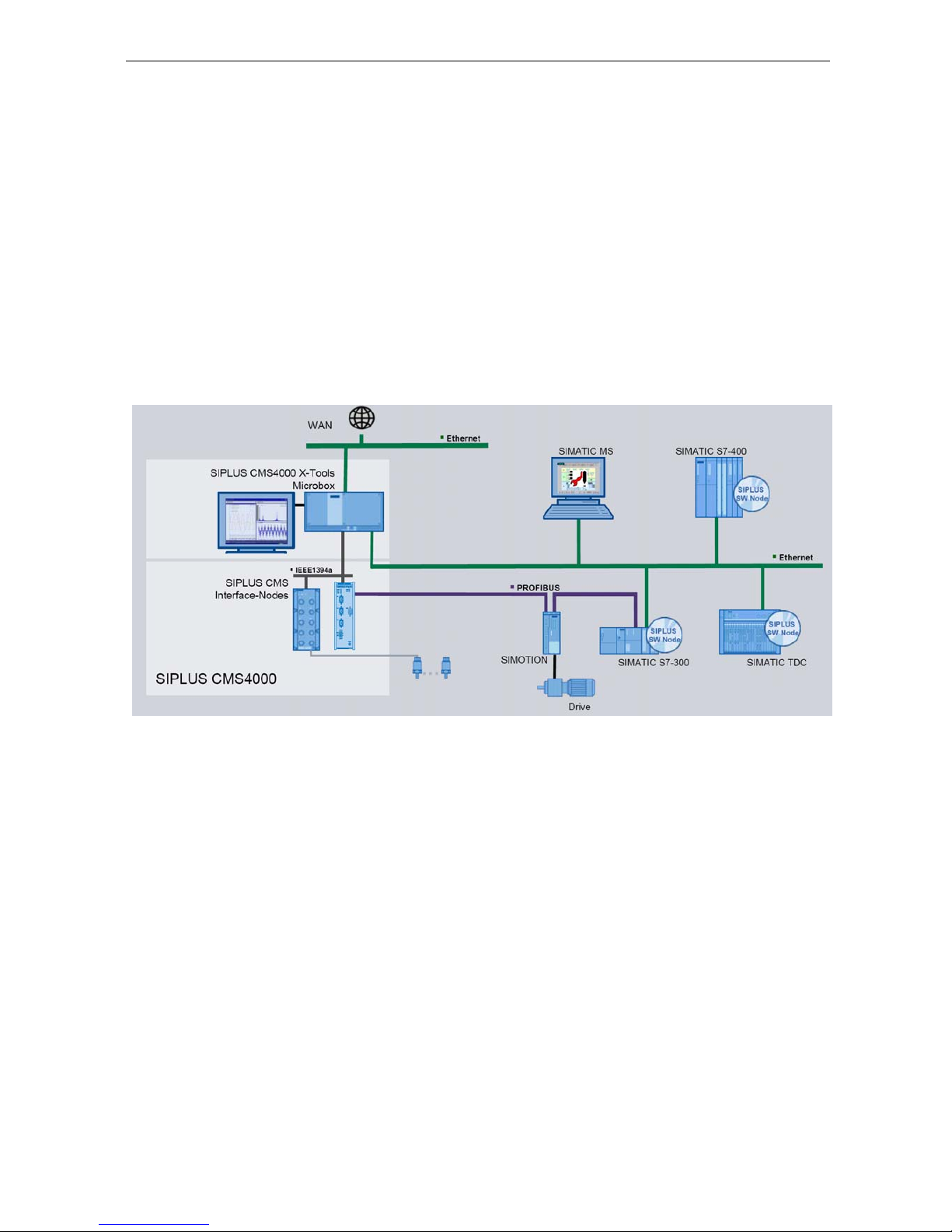
2.1 What is SIPLUS CMS?
SIPLUS CMS is an industrial-suited Condition Monitoring System for technical and technological services in industrial plants. SIPLUS CMS is a modular, scalable analysis and
diagnosis system. It is optimized for reaction less measurement of analog, binary and
numerical data. SIPLUS CMS can be integrated in existing and new industrial plants.
SIPLUS CMS can be integrated into the TIA-Architecture.
Picture 1 Typical configuration
SIPLUS CMS4000 ION BI
Operating Instructions, 03/2010, A5E02185979A-02
6
Page 7
Operating Instructions SIPLUS CMS4000 ION BINARYINPUT T001
2.2 What is an Interface Node ION BI?
Definition
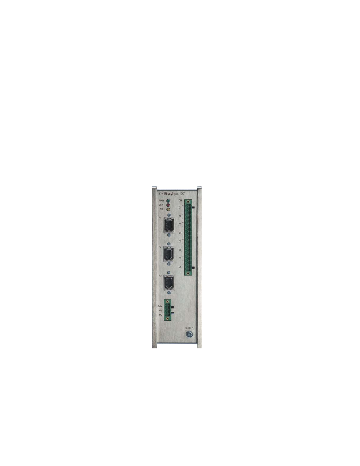
The ION BI allows the data sampling of 8 binary, separate electrically isolated signals
with a level of 0/24 V. The maximum sample rate is up to 50 kHz per channel.
Application Area
The compact design of the ION BI enables the application in space-saving ranges.
Easy handling of ION BI provides a fast commissioning and maintenance
The product is designed for the application on a DIN Rail or for mounting angles.
Display
The device ION BINARYINPUT T001 provides three plugs for further SIPLUS
CMS4000 system components and eight inputs for binary 0/24 V signals.
Picture 2 Front view ION BI
SIPLUS CMS4000 ION BI
Operating Instructions, 03/2010, A5E02185979A-02
7
Page 8

Operating Instructions SIPLUS CMS4000 ION BINARYINPUT T001
2.3 Scope of Delivery
What is delivered?
Device ION BINARYINPUT T001 (incl. clamp for DIN Rail mounting)
Operating Instructions (compact)
3-pin plug-in terminal block
PHOENIX CONTACT, COMBICON, 3 Pin MVSTBW 2,5/3-STF-5,08
16-pin plug-in terminal block
PHOENIX CONTACT, COMBICON, 16 Pin MVSTBW 2,5/16-STF-5,08
Unpacking and Checking
After unpacking, please check
the packet for completeness and
all parts for transport damages.
Warning
Do not use any parts that show signs of damage!!
SIPLUS CMS4000 ION BI
Operating Instructions, 03/2010, A5E02185979A-02
8
Page 9

Operating Instructions SIPLUS CMS4000 ION BINARYINPUT T001
3 Installation
3.1 Type of Installation
Note
The device ION BINARYINPUT T001 may exclusively be operated when installed on a DIN rail.
3.2 Installation
Installation of the device on a DIN rail:
Hang the upper table-track of the device on the DIN rail and push it down to-
wards the DIN rail so that it snaps in.
Installation of electric connection cables:
Install the terminal block of the binary connection cables.
Install the plugs of the IEEE1394 connection cables.
Install the terminal block of the power supply connection cable.
1
3
2
picture 3 installation of the ION BINARYINPUT T001 on a DIN rail
Caution
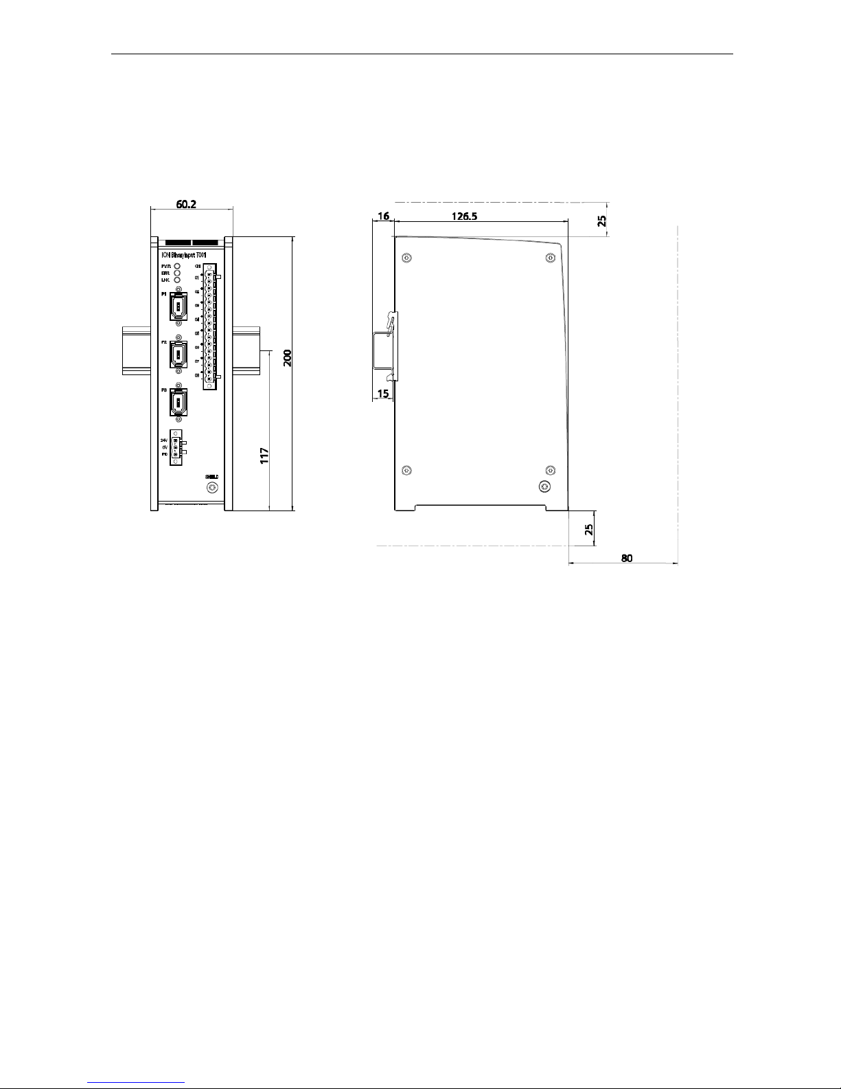
The spaces, which are specified in chapter „Appendix“, paragraph „Dimension Drawing“, on top and underneath the device (25 mm) and in front of the device (80 mm) have to be kept.
3.3 Disassembly
Disassembly of electric connection cables:
Disassemble the terminal block of the power supply connection cable.
Disassemble the plugs of the IEEE1394 connection cable.
Disassemble the terminal block of the binary connection cables.
SIPLUS CMS4000 ION BI
Operating Instructions, 03/2010, A5E02185979A-02
9
Page 10

Operating Instructions SIPLUS CMS4000 ION BINARYINPUT T001
Removal of the device from the DIN rail:
Push the device down against the DIN rail and hang it out.
SIPLUS CMS4000 ION BI
Operating Instructions, 03/2010, A5E02185979A-02
10
picture 4 disassembly of the ION BINARYINPUT T001 from the DIN rail
1
3
2
Page 11

Operating Instructions SIPLUS CMS4000 ION BINARYINPUT T001
SIPLUS CMS4000 ION BI
Operating Instructions, 03/2010, A5E02185979A-02
11
4 Wiring
4.1 General Rules and Regulations for operation of ION BI
DC 24V-Supply
The following chart shows what you have to observe for the DC24 V-Supply.
Chart 1 DC 24V-Supply
At… you must ensure that …
Buildings outside lightning protection
DC 24 V-Supply-line, Signal
transmission
inside lightning protection
Meet the requirements of lightning
protection (e.g. lightning elements)
DC 24 V-Supply safe (electrical) disconnection of low voltage
Chaining of supply voltage potential drop when chaining
For Power-Supply of the device on installation location with strong EMV-toxic load/ irradiation observe the following alternatives:
Chart 2 Recommendation for reaching the EMV- compability
Alternative Notice
Controlled power adaptor SITOP SMART
EMV Interference filter Company TIMONTA e.g. Type FMLB-0109-0640
SMD-Ferrite on both power supply ledges Company WÜRTH ELEKTRONIK, e.g. No. 74271222
Protection against external electrical influences
The following chart shows what you have to observe for the protection of electrical influences or faults.
Chart 3 Protection of electrical influences
At… you must ensure that …
all devices or systems, in which
the ION BI is installed
the device or system for conduction of electromagnetic failure on
grounding (SHIELD) is connected.
Supply, signal and bus lines correct wiring arrangement and installation.
Signal and bus lines
a line or strand breakage should not lead to an undefined situation of
the device or system.
4.2 Grounding
The screw on the front side of the device is provided as grounding connection.
Page 12
Operating Instructions SIPLUS CMS4000 ION BINARYINPUT T001
4.3 Interfaces
4.3.1 IEEE1394a Interfaces
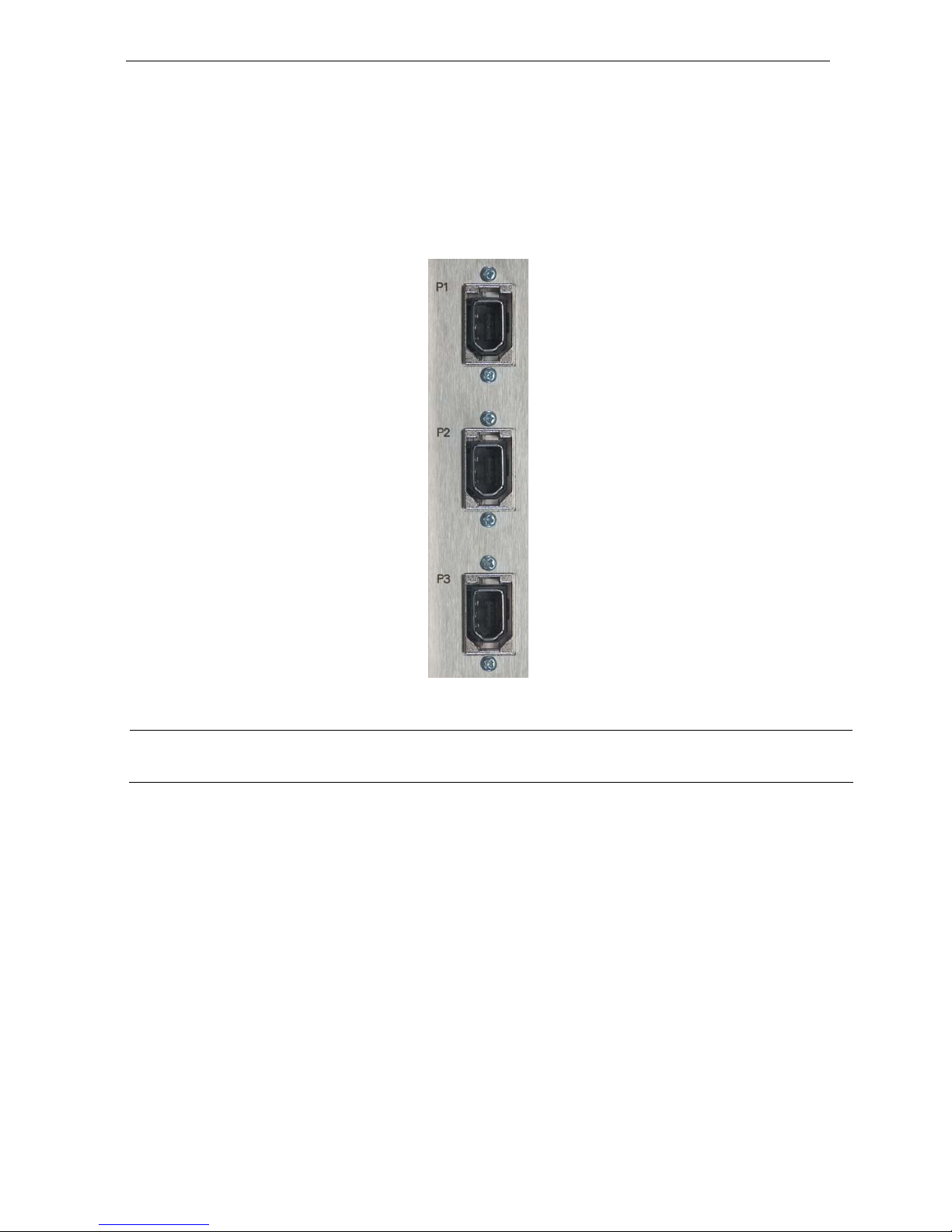
At the ION BINARYINPUT T001 the IEEE1394a Interfaces (P1 / P2 / P3) are implemented as 6-pin-sockets.
picture 5 IEEE1394a Interfaces
Caution
Only cables of a maximum length of 4.5 m may be connected to the IEEE1394a Interfaces.
4.3.2 Power Supply Interface
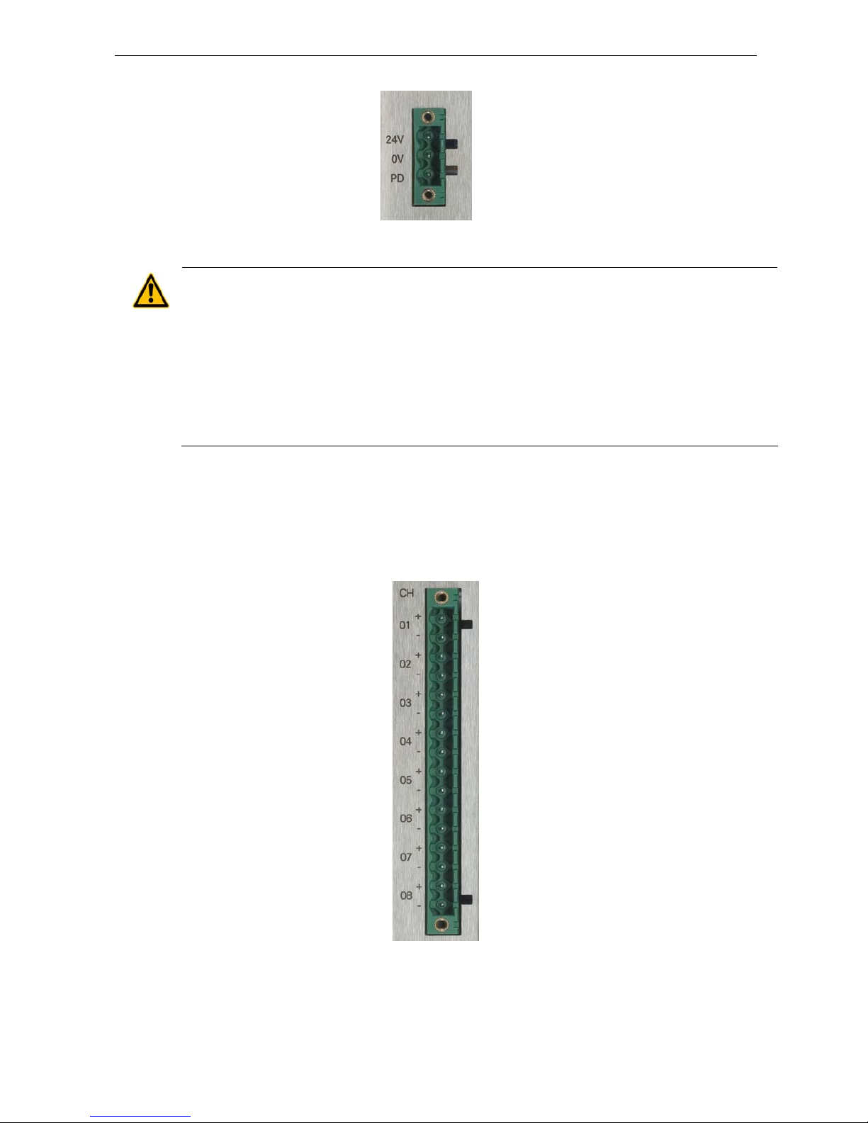
The connection takes place via a 3-pin plug-in terminal block. The power supply is
connected to the chassis via a low resistance in order to keep a high interference resistance.
The supply voltage is attached via pin 1 (24V) and pin 2 (0V).
The power feed of 24 V on pin 3 (PD - Power Down) of the terminal block of 90 seconds causes a RESET of the device. After approximately 90 seconds the device
starts automatically again.
SIPLUS CMS4000 ION BI
Operating Instructions, 03/2010, A5E02185979A-02
12
Page 13
Operating Instructions SIPLUS CMS4000 ION BINARYINPUT T001
picture 6 power supply interface
Caution
The device ION BINARYINPUT T001 is designed for operation with safety extra-low voltage. This
means that only safety extra-low voltages (SELV) complying with IEC950/EN60950/VDE0805 can
be connected to the power supply terminals.
The power supply unit for the supply of the ION BINARYINPUT T001 has to meet NEC Class 2
(range of voltage 18-32 V, maximum load of 1 A).
The ION BINARYINPUT T001 has to be protected with a fuse element of double maximum load
and tripping characteristic „medium time lag“ or „time lag“.
Never operate the ION BINARYINPUT T001 with AC voltage or DC voltage higher than 32 VDC.
4.3.3 Binary Interfaces
At the ION BINARYINPUT T001, the interface to the binary 0/24 V signals
CH 01 +/- … CH 08 +/-
is implemented as 16-pin-socket (PHOENIX, MVSTBW 2,5/16-GF-5,08).
Bild 7 binary interfaces
SIPLUS CMS4000 ION BI
Operating Instructions, 03/2010, A5E02185979A-02
13
Page 14

Operating Instructions SIPLUS CMS4000 ION BINARYINPUT T001
Caution
Only cables of a maximum length of 3.0 m may be connected to the binary inputs.
4.3.4 Indicators
picture 8 LEDs Indicators
Name
PWR
Description
power indicator
Color
green
Condition off
no operating voltage
blinks
firmware operates
Name
ERR
Description
error indicator
Color
red
Condition off
no error
on
error fan - if any
Name
LNK
Description
indicator for the connection to the controller
Color
yellow
Condition off
no connection to the controller
on
connection to the controller established
blinks
data exchange with the controller
4.3.5 Cable Traction Relief
Caution
You have to prepare adequate cable traction relief!
SIPLUS CMS4000 ION BI
Operating Instructions, 03/2010, A5E02185979A-02
14
Page 15

Operating Instructions SIPLUS CMS4000 ION BINARYINPUT T001
SIPLUS CMS4000 ION BI
Operating Instructions, 03/2010, A5E02185979A-02
15
5 Technical Data
5.1 Standards and Approvals
Product Name
Device SIPLUS CMS4000 ION BINARYINPUT T001
EMV Directive
The product is designed for use in an industrial environment.
Area of Application Requirements for
Emission Immunity
DIN EN 55011:2007 Gruppe 1, Klasse A
EN 55011:2007+A2:2007
DIN EN 61000-6-2:2006
EN 61000-6-2:2005
DIN EN 61000-4-2:2001
EN 61000-4-2:1995+A1:1998+A2:2001
DIN EN 61000-4-3:2008
EN 61000-4-3:2006+A1:2008
DIN EN 61000-4-4:2005
EN 61000-4-4:2004
DIN EN 61000-4-5:2007
EN 61000-4-5:2006
Industry
DIN EN 61000-4-6:2008
EN 61000-4-6:2007
Einsatzbereich Anforderungen an
Installation Guide Lines
The product meets the requirements if you meet the installation instructions and safetyrelated notices as described in this commissioning manual.
Conformity Certificates
The EC Declaration of Conformity is available for the responsible authorities according to
the abovementioned EC Directive at the following address:
SIEMENS AG
I IA CE DE
WUERZBURGER STR. 121
90766 FUERTH
GERMANY
Page 16

Operating Instructions SIPLUS CMS4000 ION BINARYINPUT T001
SIPLUS CMS4000 ION BI
Operating Instructions, 03/2010, A5E02185979A-02
16
Notes for the manufactures of machines
This product is not a machine in the sense of the EC Machinery Directive. There is therefore no declaration
of conformity relating to the EC Machinery Directive 89/392/ECC for this product.
If the product is part of the equipment of a machine, it must be included in the procedure for the declaration
of conformity by the manufacturer of the machine.
Page 17

Operating Instructions SIPLUS CMS4000 ION BINARYINPUT T001
SIPLUS CMS4000 ION BI
Operating Instructions, 03/2010, A5E02185979A-02
17
5.2 Technical Data
Connections
Power Supply Interface 24V / 0V / PD
Number 1
Connector type 3-pin plug-in terminal block, Phoenix Contact
Type input
Input voltage 18 ... 32 VDC
Power loss at 24 VDC 24 W
Current consumption at 24 VDC 1 A
IEEE1394a Interface P1 … P3
Number 3
Connector type 6-pin socket
Type IEEE1394a Interface
Transfer speed 400 Mbps
Standard IEEE1394a
Binary Interfaces CH 01 … 08
Number 8
Connector type 16-pin plug-in terminal block, Phoenix Contact
Type comparator input
Input voltage +/-48 V
Input protection +/-60 V
Insulation +/-0,4 kV
Electrical isolation channels are electrically isolated separately
Input current 2.5 mA ≤ I ≤ 3.5 mA
Sample frequency ≤ 50 kHz / binary input
Resolution 1 bit
Response time ≥ 4 µs
Switching threshold logic “0” +4 V > U > -4 V
Switching threshold logic “1” U > +6 V // U < -6 V
Hysteresis < 200 mV
Page 18

Operating Instructions SIPLUS CMS4000 ION BINARYINPUT T001
SIPLUS CMS4000 ION BI
Operating Instructions, 03/2010, A5E02185979A-02
18
Permitted Cable / Cable Length
FireWire according to IEEE1394a standard
Binary inputs maximum length: 3 m
Permitted Environmental Conditions / EMC
Ambient temperature during operation 0 ... +55 °C
Transportation and storage temperature -25 ... +85 °C
Humidity rating 5 ... 95 %, not condensing
EMC interference emission EN 55011 (Class A)
EMC interference immunity EN 61000-6-2:2005
Degree of protection IP20
Constructive Structure
Dimensions (H x W x D) in mm 200 x 60.2 x 126.5
Design aluminum / stainless steel
Color silver
Weight 1 kg
Mounting DIN rail profile
DIN EN 50022-35x15 (thickness 2.3 mm)
Page 19
Operating Instructions SIPLUS CMS4000 ION BINARYINPUT T001
6 Appendix
6.1 Dimensional Drawing
picture 9 Dimensional Drawing
SIPLUS CMS4000 ION BI
Operating Instructions, 03/2010, A5E02185979A-02
19
Page 20

Operating Instructions SIPLUS CMS4000 ION BINARYINPUT T001
SIPLUS CMS4000 ION BI
Operating Instructions, 03/2010, A5E02185979A-02
20
6.2 Service & Support in the Internet
In addition to our documentation pool we offer our complete knowledge base on the Internet:
www.siemens.com/automation/service&support
There you find:
The newsletter, which is constantly updated to provide you with the latest information
about your products.
The right documents via our search function under Service & Support.
The bulletin board, a worldwide knowledge exchange for users and experts.
Your local representative for Industry Automation & Drives Technologies via our
representatives database.
Information about on-site services, repairs, spare parts, and lots more you will find
under ”Support”.
6.3 List of Abbreviations
Abkürzung Begriff
CH Channel
CMS Condition Monitoring System
IEEE Institute of Electrical and Electronics Engineers
ION Node
PD Power Down
TIA Totally Integrated Automation
 Loading...