

Page 1
Operating Instructions SIPLUS CMS4000 MCN11
SIPLUSCMS4000
Media Converter Node (MCN11)
Preface 1
Product Overview 2
Installation 3
Wiring 4
6AT8000-1EB00-3XA0
Operating Instructions - English
Release 2017-06
Commissioning and Diagnosis 5
Technical Data 6
Appendix 7
SIPLUS CMS4000 MCN11
Operating Instructions, 06/2017, A5E02298098A-AA 1
Page 2
Operating Instructions SIPLUS CMS4000 MCN11
Safety Guidelines
This docu ment contains notices which you shoul d observe t o ensure your ow n pers onal safety as w ell as to avoi d propert y damage.
The notices referring to your personal safety are highlighted in the manual by a safety alert sym bol, notices referring to property
damage only have n o safety al ert symbol.
Danger
Indic ates an immin ently hazard ous s ituation which, if not avoided, will r esu lt in death or serious injury.
Warning
Indicates a potentiall y hazard ous situ at ion which, if not avoided, could r esult in death or s erious injury.
Caution
Used with the safety alert symb ol indicat es a p otentially hazardous s ituation w hich, if not avoided, m ay r esult in min or or
moderate injury.
Caution
Used with out the s afety alert s ymbol indicates a pot entially haz ardous situation which, if n ot avoided, may result in property damage.
Notice
Used without the safety alert symbol indicates a pot ential situation which, if not avoided, may result in an und esirable
result or state.
When several d anger levels apply, the notices of the highest level (lower numb er) are always dis played. If a notice refers to personal
damages w ith the saf ety alert s ymbol, then another notice may be added w arning of property d am age.
Qualified Personnel
The device / system may onl y be set up and operat ed in conjunction with this documentation. Onl y q ualified personnel should be
allowed to install and work on th e equipm ent. Qualified persons are defi ned as persons who are authori zed to commis sion, t o ear th,
and to tag circuits, equipment and systems i n accord ance with established safety practices.
Intended Use
Please note the f ollow ing:
Warning
This device and its components may only be used for the appl ications described in the catalog or tech nical description,
and only in connection with devices or components from other manufacturers appro ved or recommended by Siemens .
Trademarks
All designations marked w ith ® are registered trademarks of Siemens AG. Other designati ons in this documen tation might be tr ademarks which, if used by third parties for their pur poses, might infringe upon th e rights of the proprietors.
Copyright Siemens AG 2017. All rights reserved.
Reproduction, transmission or use of this d ocument or its contents is not p ermitted without express written aut hority. Of fenders wi ll be
liable for damages. All rights, including rights created by p atent grant or registr ation of a utility model or design, are reserved.
Disclaimer of Liability
We have checked the contents of this document for agr eement with the hardware and software described. Since deviations cannot be
preclud ed entir ely, we c annot gu arant ee full agr eemen t. H owever, th e data in th e manual are revi ewed r egular ly, and an y necess ary
corrections wil l be included in subsequent editions. Sugg estions f or improvem ent are welcomed.
Siemens AG
Digital Factory, Factory Automation
Systems Engineering
P.O. Box 23 55
90713 Fuerth
Germany
SIPLUS CMS4000 MCN11
Operating Instructions, 06/2017, A5E02298098A-AA 2
Technical data subject to change
Siemens A G 2017
Page 3

Operating Instructions SIPLUS CMS4000 MCN11
Table of Contents
1 Preface.................................................................................................................................5
1.1 Purpose of the Operating Instructions.....................................................................5
1.2 Required Basic Knowledge ....................................................................................5
1.3 Validity of this Docu men t ........................................................................................5
1.4 Modifica t ion compared w ith th e Previous Ve rsion ...................................................5
1.5 CE Mark ing ............................................................................................................5
1.6 Standa rds ..............................................................................................................5
1.7 Directory ................................................................................................................6
1.8 Recycl ing and Dispos al ..........................................................................................6
2 Produc t Overv iew ................................................................................................................7
2.1 What is SIPLUS CMS?...........................................................................................7
2.2 What is a Media Con ver ter Nod e (MC N1 1)? ...........................................................8
2.3 Scope of Delivery ...................................................................................................9
2.4 Unpacking and Checking .......................................................................................9
3 Installation ......................................................................................................................... 10
3.1 Installat ion Posi tion, Dimen sions .......................................................................... 1 0
3.2 DIN Rail ............................................................................................................... 1 1
3.2.1 Installat ion ........................................................................................................... 11
3.2.2 Disass embling ..................................................................................................... 12
3.3 Mounting Angle .................................................................................................... 13
3.3.1 Installat ion ........................................................................................................... 13
3.3.2 Disass embling ..................................................................................................... 13
3.4 Label Plate ........................................................................................................... 14
4 Wiring ................................................................................................................................ 15
4.1 Genera l Rules and Regulatio ns for operat ion of MCN11 ....................................... 15
4.2 MCN11 ................................................................................................................ 16
4.2.1 Conne cting optical fiber cable (LWL) .................................................................... 16
4.2.2 Conne cting MCN 11 to the groun d (SHI ELD ) ......................................................... 19
4.2.3 IEEE139 4 Interface (LNK) .................................................................................... 20
4.2.4 Cable Information ................................................................................................. 22
5 Commis sioni ng and Diag nosis ........................................................................................ 23
5.1 Commis sioning and Star t-up of MCN11 ................................................................ 23
5.1.1 Requiremen ts for Commiss ioning ......................................................................... 25
5.1.2 Commis sioning of MCN11 .................................................................................... 25
5.2 Diagno sis via LED-ind icators ................................................................................ 25
6 Technical Data ................................................................................................................... 26
6.1 Standa rds and Approvals ..................................................................................... 2 6
6.2 Technica l Data ..................................................................................................... 28
6.3 Appro val .............................................................................................................. 29
6.4 Use of the CMS40 0 0 in Zon e 2 po te ntially explosive atmos p h ere s ....................... 29
SIPLUS CMS4000 MCN11
Operating Instructions, 06/2017, A5E02298098A-AA 3
Page 4

Operating Instructions SIPLUS CMS4000 MCN11
7 Appendix ........................................................................................................................... 30
7.1 Order Numbe rs .................................................................................................... 30
7.2 Dimens ional Drawing ........................................................................................... 31
7.3 Service & Support on the Internet ......................................................................... 3 2
7.4 List of Abbrevia tions ............................................................................................. 3 2
SIPLUS CMS4000 MCN11
Operating Instructions, 06/2017, A5E02298098A-AA 4
Page 5

Operating Instructions SIPLUS CMS4000 MCN11
1 Preface
1.1 Purpose of the Operating Instructions
This operating instructions supports you to operate the Media Converter Node SIPLUS
CMS4000 MCN11, named MCN11 as peripheral device in the System SIPLUS
CMS4000.
1.2 Required Basic Knowledge
Basic knowledge of automation technology and equipment condition monitoring is necessary.
This operating instructions contains a description of the components, which are valid at
the time of publishing the manual. We reserve the right, to enclose product information
with current information to new components and updated components.
1.3 Validity of this Document
This operating instructions is valid for the MCN11.
1.4 Modification compared with the Previous Version
- None
Notice
You will find the version of the operating instructions in the number of the footer: A5E02298098A-AA.
1.5 CE Marking
The Media Converter Node (MCN11) meets the requirements and objectives of the EGGuideline according to 2004/108/EG.
1.6 Standards
You will find detailed information in chapter 6.1 of this operation instructions.
Notice
The specified approvals are issued when the product is marked.
SIPLUS CMS4000 MCN11
Operating Instructions, 06/2017, A5E02298098A-AA 5
Page 6

Operating Instructions SIPLUS CMS4000 MCN11
1.7 Directory
The operating instructions describe the hardware of the Media Converter Node MCN11.
It contains the following topics:
• Installati on and wiring (Chapter 3 and 4)
• Commissioning and di agnosis (Chapter 5)
• Order Numbers (Chapter 7)
• Li st of abbreviations with explanation of the general definiti ons of the used terms
(Chapter 7)
1.8 Recycling and Disposal
The MCN11 is environm ental compatibility and recyclable.
For environmentally compatible recycling and disposal of your old device contact a certi-
fied waste disposal for electronic.
SIPLUS CMS4000 MCN11
Operating Instructions, 06/2017, A5E02298098A-AA 6
Page 7
Operating Instructions SIPLUS CMS4000 MCN11
2 Product Overview
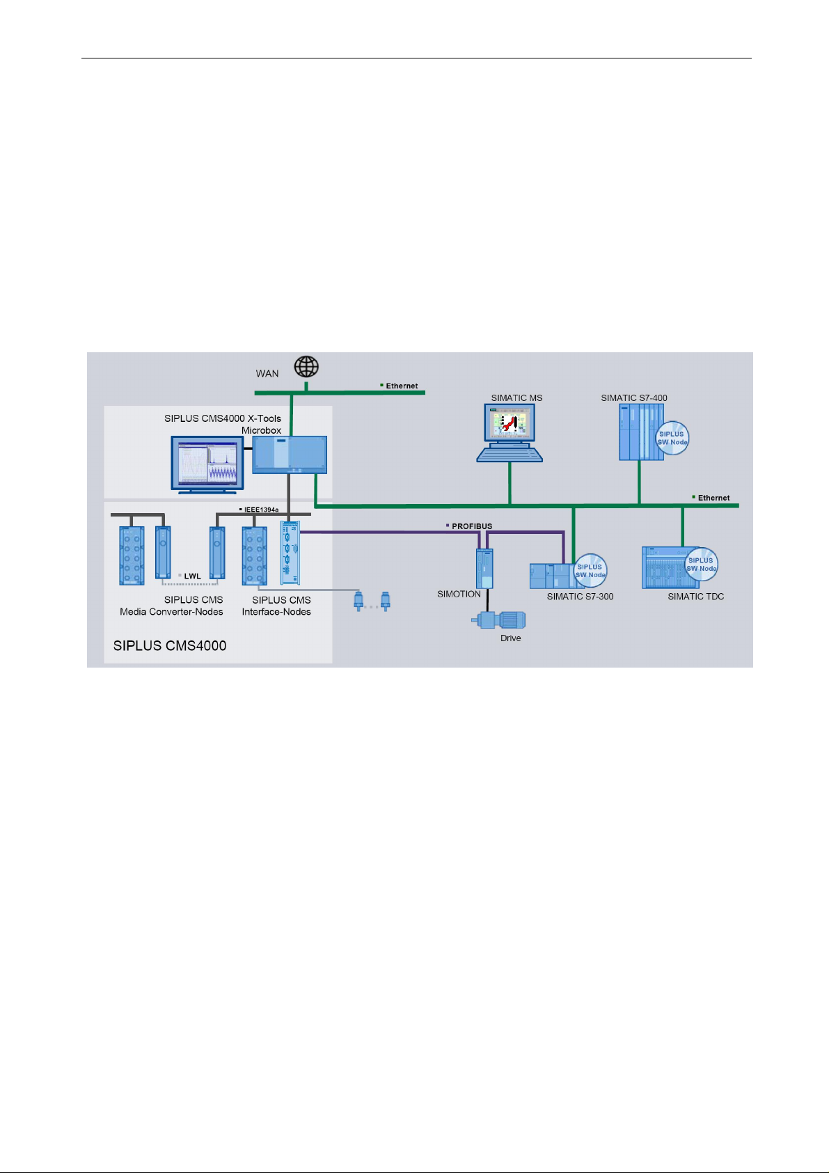
2.1 What is SIPLUS CMS?
SIPLUS CMS is an industrial-suited Condition Monitoring System for technical and technological services in industrial plants. SIPLUS CMS is a modular, scalable analysis and
diagnosis system. It is optimized for reaction less measurement of analog, binary and
numerical dat a. SIPLUS CMS can be integrated in existing and new industrial plants.
SIPLUS CMS can be i ntegrated into the TIA-Architecture.
Picture 1 Typical Configuration
SIPLUS CMS4000 MCN11
Operating Instructions, 06/2017, A5E02298098A-AA 7
Page 8
Operating Instructions SIPLUS CMS4000 MCN11
2.2 What is a Media Converter Node (MCN11)?
Definition
The MCN11 transforms the transmitting data at physical layer from one medium (electrical) to another medium (optical) and vice versa. MCN11 is used for the communication,
when the linking length is longer than 4.5 meters.
Application Area
• T he MCN11 is suited for the application in the industrial environment, because of the
robust constructi on and the degree of protection IP67.
• The compact design of the MCN11 enables the application in space-saving ranges.
• Easy handling of MCN11 provides a fast commissioni ng and maintenance
• T he product is designed for the application on a DIN Rail or for mounting angles.
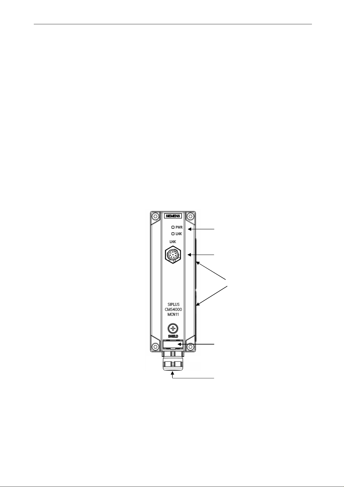
Display
The MCN11 has two displays, one I EEE1394 connection and one optical fiber (LWL)cable entry.
Picture 2 Front View MCN11
Status Display:
• PWR (green LED)
• LNK (yellow LED)
IEEE1394 Connection (LNK)
Name Plate
(right d evice site, 2- pices)
Label Plate
LWL Cable Entry
SIPLUS CMS4000 MCN11
Operating Instructions, 06/2017, A5E02298098A-AA 8
Page 9

Operating Instructions SIPLUS CMS4000 MCN11
2.3 Scope of Delivery
• Device MCN11
- incl. clamp for DIN Rail mounting
- LWL Cable entry for LWL twin connectors (other LWL Types on request)
• Operating Instructions (compact)
2.4 Unpacking and Checking
After unpacking, please check
• the packet for completeness and
• all parts f or transport damages.
Warning
Do not use any parts that show signs of damage!
SIPLUS CMS4000 MCN11
Operating Instructions, 06/2017, A5E02298098A-AA 9
Page 10
Operating Instructions SIPLUS CMS4000 MCN11
3 Installation
3.1 Installation Position, Dimensions
Installation Position
The MCN11 is suited for installation on a DIN rail or for attachment with mounting
angles.
Dimension and Expansion Spaces
Chart 1 Dimensions with and without DIN rail/mounting angles
Dimensions in mm MCN11 without
installation
Installation face length 160 160 177
Installation height 46 46 46
Installation depth 56 65 66
MCN11 with DIN Rail
MCN11 with mounting
angles
Picture 3 Correct Installation Positi on
Caution
The minimum spaces which ar e specified in chapter 6.2 on top and underneath the device and in front of
the device have to be kept.
SIPLUS CMS4000 MCN11
Operating Instructions, 06/2017, A5E02298098A-AA 10
Page 11

Operating Instructions SIPLUS CMS4000 MCN11
3.2 DIN Rail
Characteristics
The device can be installed on a DIN rail.
3.2.1 Installation
Requirements
The table-track is installed on the device.
Procedure
Hang the upper tabl e-track of the device on the DIN rail and push it down towards the
DIN rail so that it snaps in.
1
2
Picture 4 Installation of the device on a DIN rail.
Caution
During operation with vibration load use an attachment with mounting angels.
3
SIPLUS CMS4000 MCN11
Operating Instructions, 06/2017, A5E02298098A-AA 11
Page 12

Operating Instructions SIPLUS CMS4000 MCN11
3.2.2 Disassembling
Procedure
Make sure that all electronic connection cables are dissembled professionall y.
Remove the device from the DIN rail: Push the device down against the DIN rail and
hang it out.
1
2
Picture 5 Disassembly of the MCN11 from the DIN rail
3
SIPLUS CMS4000 MCN11
Operating Instructions, 06/2017, A5E02298098A-AA 12
Page 13

Operating Instructions SIPLUS CMS4000 MCN11
3.3 Mounting Angl e
Characteristics
The device will be installed with mounting angles on a stable base (e.g. wall,
mounting plate).
3.3.1 Installation
Requirements
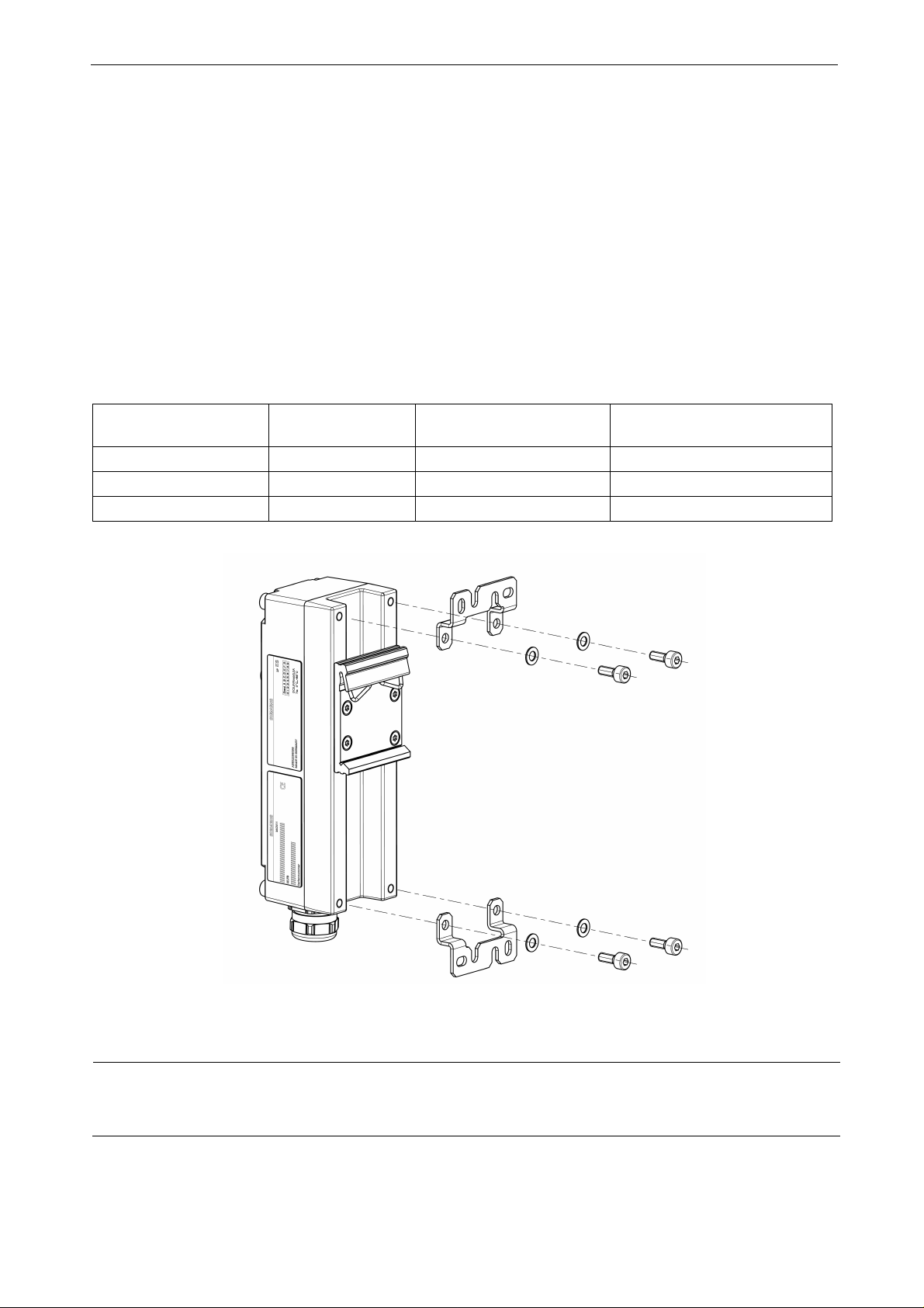
The „MCN11 Mounting Set“ is necessary for the installation with mounting angles.
In the „MCN11 Mounting Set“ is a drill template included in the equipment pack.
Order Number see chapter 7.1.
Procedure
Connect the mounti ng angles with the included screws and ring washers to the two connection positi ons on the dev ice (backside top and bottom).
Install the device on a stable base.
Picture 6 Connection of the mounting angle on the device (e.g. backside below)
3.3.2 Disassembling
Procedure
Make sure that all electronic connection cables are dissembled professionall y.
Demount the device from the site of installation (e.g. wall).
SIPLUS CMS4000 MCN11
Operating Instructions, 06/2017, A5E02298098A-AA 13
Page 14

Operating Instructions SIPLUS CMS4000 MCN11
3.4 Label Plate
Characteristics
You can mark the device with a label plate. The label plate is exchangeable.
Exchanging the label plate
1. Push the screwdriver in the small opening on the bottom edge of the label plate and
hang it out.
Picture 7 Hang the l abel plate careful out
2. Push the label plate with the finger in the indentation.
SIPLUS CMS4000 MCN11
Operating Instructions, 06/2017, A5E02298098A-AA 14
Page 15

Operating Instructions SIPLUS CMS4000 MCN11
4 Wiring
4.1 General Rules and Regulations for operation of MCN11
Protection against external electrical influences
The following chart shows what you have to observe for the protection of electrical influences or faults.
Chart 2 Protection against external electrical influences
At… you must ensure that …
all devices or systems, in which
the MCN11 is installed
Supply, signal and bus li nes correct wiring arrangement and installation.
Signal and bus lines a line or strand breakage should not lead to an undefined situat ion of
Grounding
See chapter 4.2.2 „Connecting MCN11 to grounding“.
the device or system for conduction of electromagnetic failure on
grounding is connect ed.
the device or system.
SIPLUS CMS4000 MCN11
Operating Instructions, 06/2017, A5E02298098A-AA 15
Page 16

Operating Instructions SIPLUS CMS4000 MCN11
4.2 MCN11
4.2.1 Connecting optical fiber cable (LWL)
1. Open the 4 screws on the devi ce with an Allen key (SW3).
Picture 8 Open all 4 screws
2. Release only the screwcap of the screw connection (PG-screwing) and pull the
„SC/PC-plug“ of the LWL single conductor in the right position through the screwcap.
Cable ins ert
Screwcap
Picture 9 Release screwcap
3. Remove the sealing insert and insert the LWL-single connectors in the suited lead-
through of the folding sealing insert.
Caution
Avoid a mechanical overload (e.g. bending) of the optical fiber cable!
SIPLUS CMS4000 MCN11
Operating Instructions, 06/2017, A5E02298098A-AA 16
Page 17

Operating Instructions SIPLUS CMS4000 MCN11
Sealing insert
4. Insert t he „SC/PC-plug“ of the LWL-single connectors separately through the cable
entry in the box.
Screwcap
SC/PC-plug
Picture 10 LWL-c able entry configuration
5. Connecting „SC/PC-Plugs“.
Case screw (4x)
Cable entry
Device 1
▼▲
Device 2
▼▲
▼ Transmitter Connector
▲ Receiver Connector
Picture 11 Connecting twin cable (View on the device like in picture 12 shown)
Caution
Please consider, when connecting the pl ug that the transmitter (Device 1) is connected with the receiver
(Device 2).
SIPLUS CMS4000 MCN11
Operating Instructions, 06/2017, A5E02298098A-AA 17
Page 18

Operating Instructions
SIPLUS CMS4000 MCN11
6. Slide the sealing insert flush in the cable entry so that the LWL-single connect or lays
parallel in the box (in order to avoid a mechanical overload of LWL).
7. Screw and tighten the screwcap on to the cable entry. Recommended tightening
torque: 10Nm
Picture 12 Finished installation
8. Close the casing cover and screw the 4 included screws (from 1) tight. The recom-
mended torque: 3Nm.
Caution
Only when the install ation is correct, the screwcap fi ts tight and the cover screw fits tight the protection
category IP67 is guaranteed.
Never pull and insert optical fiber, when the ambient temperature is 0° Celsius and below (risk of breakage).
SIPLUS CMS4000 MCN11
Betri ebsanleitu ng, 06/20 17, A5E02298098A-AA 18
Page 19

Operating Instructions
SIPLUS CMS4000 MCN11
4.2.2 Connecting MCN11 to the ground (SHIELD)
The earth connecti on has to be im plem ented with cable cross section of 2,5mm
2
1. Isolate the grounding cable and squeeze a cable lug at the end of the line (M4 ring
eye).
2. Screw the cable lug to the device as shown in the picture. The recommended torque
is 3 Nm.
Picture 13 Connecting MCN11 to the ground (SHIELD)
SIPLUS CMS4000 MCN11
Operating Instructions, 06/2017, A5E02298098A-AA 19
Page 20

Operating Instructions
Knurled ring nut
M12 connector
SIPLUS CMS4000 MCN11
4.2.3 IEEE1394 Interface (LNK)
Connect the M12 connector on the front side of the box in the 8-pin socket pl ug (LNK).
For this purpose use the cable with the order number (MLFB) 6AT8000-2AB20-2AA2.
Caution
Using standard SIPLUS CMS cables is necessary. In case of using self-made cable connection there is no
warranty assumed.
The pictures 14, 15 and 16 shall only explain the concept of the plug type. The principle handling stays the
same.
1. Push the M12 connector in vertical position in the socket plug, so that the slot from the
connector and knurled ring nut are superposed.
Socket plug
Picture 14 Connecting M12 connector
SIPLUS CMS4000 MCN11
Operating Instructions, 06/2017, A5E02298098A-AA 20
Page 21

Operating Instructions
SIPLUS CMS4000 MCN11
2. Twist the M12-socket plug with the knurled ring nut tight until it snaps. (about 1/2 rota-
tion).
Picture 15 M12-socket plug interlocking
3. The end position (interlock) of the M12-socket plug is now finished.
Picture 16 Correct M12-socket plug connection
Caution
Avoid canting between M12 connector and socket plug!
Only when the install ation is correct, the prot ection category IP67 and safe contacting is guaranteed.
Never pull and insert cables and plugs, when the ambient temperature is 0° Celsius and below.
SIPLUS CMS4000 MCN11
Operating Instructions, 06/2017, A5E02298098A-AA 21
Page 22

Operating Instructions
SIPLUS CMS4000 MCN11
4.2.4 Cable Information
Depending on the LWL cable an adequate sealing insert is needed. The integrated sealing is suitable for LWL cable with 3mm diameter.
Caution
The laying information of the LWL-cable manufacturer has to be observed.
SIPLUS CMS4000 MCN11
Operating Instructions, 06/2017, A5E02298098A-AA 22
Page 23

Operating Instructions
SIPLUS CMS4000 MCN11
5 Commissioning and Diagnosis
5.1 Commissioning and Start-up of MCN11
Caution
Plugging and pulling between the electrical connection between MCN11 and I FN is acceptable with voltage
and without voltage.
Notice that the life-time of the cable and MCN11 reduces, when pulling and plugging with voltage.
Possible Connection Configuration
The MCN11 can be connected to every possible IEEE1394 – i nterface (LNK0/1/2) from
the IFN. In the process up to three MCN11 can be operated with one IFM, if the minimum distances are kept.
IFN/MCN-Cable
Interface Node (IFN)
Media Converter
Node (MCN11)
LWL
Media Converter
Node (MCN11)
Interface Node (IFN)
IFN/MCN-Cable
Picture 17 Exam ple of the connection configuration with LWL-cabling bet ween two IFN’s
SIPLUS CMS4000 MCN11
Operating Instructions, 06/2017, A5E02298098A-AA 23
Page 24

Operating Instructions
SIPLUS CMS4000 MCN11
PC / SIPLUS CMS Microbox
Multi-Port-Repeater
(RPN IEEE1394B T001/T002)
RPN/PC-Cable
Media Converter
Node (MCN11)
LWL
IFN/MCN-Cable
Picture 18 Exam ple of the connection configuration between PC and CMS4000 System
SIPLUS CMS4000 MCN11
Operating Instructions, 06/2017, A5E02298098A-AA 24
Page 25

Operating Instructions
SIPLUS CMS4000 MCN11
5.1.1 Requirements for Commissioning
1. MCN11 mounted (view chapter 3).
2. MCN11 wired (view chapter 4) .
5.1.2 Commissioning of MCN11
Picture 19 Start-up of MCN11
5.2 Diagnosis via LED-indicators
Name
Description
Color
Condition off
on
Name
Description
Color
Condition off
blinks
on
SIPLUS CMS4000 MCN11
Operating Instructions, 06/2017, A5E02298098A-AA 25
PWR
power indicator
green
no operation voltage
voltage supply exi sting (ready to operate)
LNK
indicator for optical coupling
yellow
no connection of optical coupling
optical coupling erroneous (e.g. LWL not plugged i n correct)
optical coupling established
Page 26

Operating Instructions
SIPLUS CMS4000 MCN11
6 Technical Data
6.1 Standards and Approvals
Product Name
Device SIPLUS CMS4000 MCN11
EMV Directive
The product is designed for use in industrial environment.
Area of Application Requirements for
Emission Immunity
Industry DIN EN 55011:2007 Group 1, class A
EN 55011:2007+A2:2007
Installation Guide Lines
The product meets the requirements if you meet the installation instructions and safety-
related notices as described in this operating instructions.
Conformity Certificates
The EC Declaration of Conformity is available fort he responsible authorities according to
the abovementioned EC Directive at the following address:
DIN EN 61000-6-2:2006
EN 61000-6-2:2005
DIN EN 61000-4-2:2001
EN 61000-4-2:1995+A1:1998+A2:2001
DIN EN 61000-4-3:2008
EN 61000-4-3:2006+A1:2008
DIN EN 61000-4-4:2005
EN 61000-4-4:2004
DIN EN 61000-4-5:2007
EN 61000-4-5:2006
DIN EN 61000-4-6:2008
EN 61000-4-6:2007
SIEMENS AG
DF FA SE
BRESLAUER STR. 5
90766 FUERTH
GERMANY
SIPLUS CMS4000 MCN11
Operating Instructions, 06/2017, A5E02298098A-AA 26
Page 27

Operating Instructions
SIPLUS CMS4000 MCN11
Notes for the manufactu res of machines
This product is not a machine in the sense of the EC Machinery Directive. There is therefore no declaration
of conformity relating to the EC Machinery Directive 89/392/ECC for this product.
If the product is part of the equipment of a machine, it must be included in the procedure for the declaration
of conformity by the manufacturer of the machine.
Safety information
Warning
Personal injury and damage to property may occur
In hazardous areas, injury to persons and material damage may occur if you disconnect
plug-in connect ions during operation of a CMS4000 system.
Always switch off the power t o the CMS4000 system when disconnect ing plug-in connections in potentially explosive atmospheres.
Warning
Explosion hazard
If you replace c omponents, compliance with Zone 2 could be compromised.
Warning
Deployment requi rements
This device is only appropriate for use in Zone 2 or in nonhazardous areas.
SIPLUS CMS4000 MCN11
Operating Instructions, 06/2017, A5E02298098A-AA 27
Page 28

Operating Instructions
Interfaces and connections
IEEE
1394a electrical
Number
1
Connector type
8-pin receptacle connect or (M12)
Transfer speed
400 Mbps
Applicable cable
Tailor made 8
-
pin cable with shield (length: 30 cm)
Power input MCN11
ca. 0.6 W
IE
EE 1394b optical
Number
1
Connector type
Duplex SC/PC 62.5 / 125
µ
m Multimode
-
Fiber (MMF)
Wavelength
850 nm
Transfer speed
400 Mbps
Applicable optical fiber
50 / 125
µ
m MMF up to 500 m Length
Shield
Connector typ
e
M4 screw on the front (SHIELD)
Clamping range
Cable socket for screw M4
Environment al Conditions
Ambient temperature during
±0°
...
+ 65°CTransport and storage temperature
-40...
+ 85°CInstallation height over NN
< 2000 m
Degree o
f protection
IP67
Constructive Layout
Dimensions (H x W x D) in mm
160 x 46 x 56
without DIN rail and mounting angle
Design
Aluminum
Mounting
Standard:
DIN rail (DIN EN 60715T H35
-
15)
Minimum distances:
SIPLUS CMS4000 MCN11
6.2 Technical Data
(connection: IFN to MCN11)
operation
MLFB: 6AT8000-2AB20-2AA2
62.5 / 125 µm MMF up to 220 m Length
160 x 46 x 65 with DIN rail
177 x 46 x 66 with mounting angle
Optional: Mounting angle (Order Number in chapter 7.1
MCN Mounting Set)
(front, top, bottom) in mm 80, 25, 25
SIPLUS CMS4000 MCN11
Operating Instructions, 06/2017, A5E02298098A-AA 28
Page 29

Operating Instructions
SIPLUS CMS4000 MCN11
6.3 Approval
Chart 3 Approval
Approval Mark
Declaration of conformity
ATEX approval
II 3G Ex nA IIC T4 Gc
DEK 14 ATEX 0084 X
IECEx approval
EAC certification
KC certification
RCM c ertification
IECEx DEK 14.0040 X
6.4 Use of the CMS4000 in Zone 2 potentially explosive atmospheres
See product inf ormation Deployment of the modules in zone 2 potentially explosive atm ospheres
(http://support.automation.siemens.com/WW/view/en/104933030).
SIPLUS CMS4000 MCN11
Operating Instructions, 06/2017, A5E02298098A-AA 29
Page 30

Operating Instructions
SIPLUS CMS4000 MCN11
7 Appendix
7.1 Order Numbers
Product Order Number(MLFB)
SIPLUS CMS4000 MCN11 6AT8000-1EB00-3XA0
SIPLUS CMS4000 MCN11 Operating Instructions Download view chapter 7.3
SIPLUS CMS „MCN Mounting Set“ for installation wi th
mounting angle incl. drill template
Cable
IEEE1394 IFN/MCN cable
Length 30 cm 6AT8000-2AB20-2AA2
6AT8000-2BB00-0XC0
Further information is available from your local Siemens office and from the homepage
www.siemens.com/siplus-cms.
SIPLUS CMS4000 MCN11
Operating Instructions, 06/2017, A5E02298098A-AA 30
Page 31

Operating Instructions
SIPLUS CMS4000 MCN11
7.2 Dimensional Drawing
SIPLUS CMS4000 MCN11
Operating Instructions, 06/2017, A5E02298098A-AA 31
Page 32

Operating Instructions
SIPLUS CMS4000 MCN11
7.3 Service & Support on the Internet
In addition to our doc um entation pool we offer our complete knowledge base on the In-
ternet:
www.siemens.com/automation/service&support
There you find:
• The newsletter, which is constantly updated to provide you with the latest informati on
about your products.
• The right documents via our search function under Service & Support.
• The bulletin board, a worldwide knowledge exchange for users and experts.
• Your local representative for Industry Automation & Drives Technologies via our
representatives database.
• Inf ormation about on-site services, repairs, spare parts, and lots more you will find
under ”Support”.
7.4 List of Abbreviations
Abbre v iation Item
CMS Condition Monitoring System
IEEE Institut e of Electrical and Electronics Engineers
IFN Interface Node
LWL Optical Fiber (cable)
MCN11 Media Converter Node
TIA Totally Integrated Automati on
SIPLUS CMS4000 MCN11
Operating Instructions, 06/2017, A5E02298098A-AA 32
 Loading...