

Siemens SIPART Series, SIPART PS2 Series Operating Instructions Manual
SIPART
Electropneumatic positioners
SIPART PS2 with and without HART
Operating Instructions
Edition 10/2013
Answers for industry.


SIPART PS2 with and without HART
___________________
___________________
___________________
___________________
___________________
___________________
___________________
___________________
___________________
___________________
___________________
___________________
___________________
___________________
___________________
SIPART
Electropneumatic positioners
SIPART PS2 with and without
HART
Operating Instructions
6DR50.. - Positioner without HART
6DR51..
6DR52..
6DR53..
proof
10/2013
A5E00074631
Introduction
1
Safety information
2
Description
3
Installing/mounting
4
Connection
5
Operating
6
Commissioning
7
Functional safety
8
Parameterizing/addressing
9
Alarm, error, and system
messages
10
Service and maintenance
11
Technical data
12
Dimension drawings
13
Spare
parts/accessories/scope of
delivery
14
Appendix
A
Abbreviations
B
- Positioner with HART, not explosion-proof
- Positioner with HART, explosion-proof
- Positioner without HART, not explosion-
-11
Siemens AG
Industry Sector
Postfach 48 48
90026 NÜRNBERG
GERMANY
Order number: A5E00074631
Ⓟ
Copyright © Siemens AG 2013.
All rights reserved
Warning notice system
DANGER
indicates that death or severe personal injury will result if proper precautions are not taken.
WARNING
indicates that death or severe personal injury may result if proper precautions are not taken.
CAUTION
indicates that minor personal injury can result if proper precautions are not taken.
NOTICE
indicates that property damage can result if proper precautions are not taken.
Qualified Personnel
personnel qualified
Proper use of Siemens products
WARNING
Siemens products may only be used for the applications described in the catalog and in the relevant technical
maintenance are required to ensure that the products operate safely and without any problems. The permissible
ambient conditions must be complied with. The information in the relevant documentation must be observed.
Trademarks
Disclaimer of Liability
Legal information
This manual contains notices you have to observe in order to ensure your personal safety, as well as to prevent
damage to property. The notices referring to your personal safety are highlighted in the manual by a safety alert
symbol, notices referring only to property damage have no safety alert symbol. These notices shown below are
graded according to the degree of danger.
If more than one degree of danger is present, the warning notice representing the highest degree of danger will
be used. A notice warning of injury to persons with a safety alert symbol may also include a warning relating to
property damage.
The product/system described in this documentation may be operated only by
task in accordance with the relevant documentation, in particular its warning notices and safety instructions.
Qualified personnel are those who, based on their training and experience, are capable of identifying risks and
avoiding potential hazards when working with these products/systems.
for the specific
Note the following:
documentation. If products and components from other manufacturers are used, these must be recommended
or approved by Siemens. Proper transport, storage, installation, assembly, commissioning, operation and
All names identified by ® are registered trademarks of Siemens AG. The remaining trademarks in this publication
may be trademarks whose use by third parties for their own purposes could violate the rights of the owner.
We have reviewed the contents of this publication to ensure consistency with the hardware and software
described. Since variance cannot be precluded entirely, we cannot guarantee full consistency. However, the
information in this publication is reviewed regularly and any necessary corrections are included in subsequent
editions.
09/2013 Technical data subject to change

Table of contents
1 Introduction ............................................................................................................................................. 9
2 Safety information ................................................................................................................................. 13
3 Description ............................................................................................................................................ 17
4 Installing/mounting ................................................................................................................................ 31
1.1 Purpose of this documentation ...................................................................................................... 9
1.2 History ............................................................................................................................................ 9
1.3 Purpose ........................................................................................................................................ 10
1.4 Checking the consignment ........................................................................................................... 10
1.5 Transportation and storage .......................................................................................................... 11
1.6 Product information ...................................................................................................................... 11
1.7 Notes on warranty ........................................................................................................................ 11
2.1 Requirements for safe use ........................................................................................................... 13
2.1.1 Warning symbols on the device ................................................................................................... 13
2.1.2 Laws and directives ..................................................................................................................... 14
2.1.3 Conformity with European directives ........................................................................................... 14
2.2 Improper device modifications ..................................................................................................... 15
2.3 Requirements for special applications ......................................................................................... 15
2.4 Use in hazardous areas ............................................................................................................... 16
3.1 Function ....................................................................................................................................... 17
3.2 Structure ....................................................................................................................................... 18
3.2.1 Overview of structure ................................................................................................................... 18
3.2.2 Nameplate layout ......................................................................................................................... 21
3.3 Device components ..................................................................................................................... 23
3.3.1 Overview of device components .................................................................................................. 23
3.3.2 Basic electronics .......................................................................................................................... 25
3.4 Mode of operation ........................................................................................................................ 26
3.4.1 Control algorithm .......................................................................................................................... 27
3.4.2 Block circuit diagram for signal-acting or dual-acting drives ........................................................ 28
3.4.3 Mode of operation of the HART function ..................................................................................... 29
3.4.4 HART system configuration ......................................................................................................... 29
3.4.5 SIMATIC PDM .............................................................................................................................. 30
4.1 Basic safety instructions .............................................................................................................. 31
4.1.1 Proper mounting........................................................................................................................... 34
4.2 Mounting the linear actuator ........................................................................................................ 34
4.3 Mounting the part-turn actuator.................................................................................................... 40
SIPART PS2 with and without HART
Operating Instructions, 10/2013, A5E00074631-11
3

Get more information
www.siemens.de/processautomation
www.siemens.de/sipartps2
Siemens AG
Industry Sector
Postfach 48 48
90026 NÜRNBERG
GERMANY
www.siemens.com/automation
Subject to change without prior notice
A5E00074631-11
© Siemens AG 2013
A5E00074631-11
A5E00074631-11

Table of contents
7 Commissioning ................................................................................................................................... 113
8 Functional safety ................................................................................................................................. 141
9 Parameterizing/addressing .................................................................................................................. 147
6.2.1 Overview of operating modes .................................................................................................... 104
6.2.2 Changing the operating mode .................................................................................................... 105
6.2.3 Overview of configuration .......................................................................................................... 106
6.2.4 Description of operating modes ................................................................................................. 107
6.3 Optimizing the controller data .................................................................................................... 110
7.1 Basic safety instructions ............................................................................................................ 113
7.2 Sequence of automatic initialization .......................................................................................... 117
7.3 Purge air switching ..................................................................................................................... 122
7.4 Commissioning linear actuators ................................................................................................. 123
7.4.1 Preparing linear actuators for commissioning ............................................................................ 123
7.4.2 Automatic initialization of linear actuators .................................................................................. 124
7.4.3 Manual initialization of linear actuators ...................................................................................... 128
7.5 Commissioning part-turn actuators ............................................................................................ 132
7.5.1 Preparing part-turn actuators for commissioning ....................................................................... 132
7.5.2 Automatic initialization of part-turn actuators ............................................................................. 133
7.5.3 Manual initialization of part-turn actuators ................................................................................. 135
7.6 Device replacement ................................................................................................................... 138
8.1 Range of applications for functional safety ................................................................................ 141
8.2 Safety function ........................................................................................................................... 141
8.3 Safety Integrity Level (SIL) ......................................................................................................... 143
8.4 Settings ...................................................................................................................................... 144
8.5 Safety characteristics ................................................................................................................. 144
8.6 Maintenance/check .................................................................................................................... 145
9.1 Parameter chapter ..................................................................................................................... 147
9.2 Configuration schematic for parameter operating principle ....................................................... 148
9.3 Overview of parameters ............................................................................................................. 149
9.3.1 Overview of parameters 1 to 5 ................................................................................................... 149
9.3.2 Overview of parameters 6 to 51 ................................................................................................. 150
9.3.3 Overview parameters A to P ...................................................................................................... 154
9.4 Description of parameters .......................................................................................................... 158
9.4.1 Description of parameters 1 through 5 ...................................................................................... 158
9.4.2 Description of parameters 6 through 51 .................................................................................... 161
9.4.2.1 Description of parameters 6 ....................................................................................................... 161
9.4.2.2 Description of parameters 7 ....................................................................................................... 161
9.4.2.3 Description of parameters 8 and 9 ............................................................................................. 162
9.4.2.4 Description of parameters 10 and 11 ......................................................................................... 163
9.4.2.5 Description of parameters 12 ..................................................................................................... 163
9.4.2.6 Description of parameters 13 through 33 .................................................................................. 164
9.4.2.7 Description of parameters 34 ..................................................................................................... 165
SIPART PS2 with and without HART
Operating Instructions, 10/2013, A5E00074631-11
5

Table of contents
10 Alarm, error, and system messages ..................................................................................................... 201
9.4.2.8 Description of parameters 35 and 36 ........................................................................................ 165
9.4.2.9 Description of parameters 37 .................................................................................................... 165
9.4.2.10 Description of parameters 38 .................................................................................................... 167
9.4.2.11 Description of parameters 39 .................................................................................................... 167
9.4.2.12 Description of parameters 40 and 41 ........................................................................................ 168
9.4.2.13 Description of parameters 42 and 43 ........................................................................................ 168
9.4.2.14 Description of parameters 44 .................................................................................................... 170
9.4.2.15 Description of parameters 45 and 46 ........................................................................................ 171
9.4.2.16 Description of parameters 47 .................................................................................................... 171
9.4.2.17 Description of parameters 48 .................................................................................................... 172
9.4.2.18 Description of parameters 49 .................................................................................................... 172
9.4.2.19 Description of parameters 50 .................................................................................................... 173
9.4.2.20 Description of parameters 51 .................................................................................................... 174
9.4.3 Description of parameters A through P ..................................................................................... 176
9.4.3.1 Description of parameter A ....................................................................................................... 176
9.4.3.2 Description of parameter b ........................................................................................................ 179
9.4.3.3 Description of parameter C ....................................................................................................... 181
9.4.3.4 Description of parameter d ........................................................................................................ 183
9.4.3.5 Description of parameter E ....................................................................................................... 185
9.4.3.6 Description of parameter F........................................................................................................ 186
9.4.3.7 Description of parameter G ....................................................................................................... 188
9.4.3.8 Description of parameter H ....................................................................................................... 190
9.4.3.9 Description of parameter J ........................................................................................................ 192
9.4.3.10 Description of parameter L ........................................................................................................ 194
9.4.3.11 Description of parameter O ....................................................................................................... 196
9.4.3.12 Description of parameter P ....................................................................................................... 198
10.1 Output of system messages in the display ............................................................................... 201
10.1.1 System messages before initialization ...................................................................................... 201
10.1.2 System messages during initialization ...................................................................................... 202
10.1.3 System messages when exiting the Configuration mode ......................................................... 205
10.1.4 System messages during operation .......................................................................................... 206
10.2 Diagnosis................................................................................................................................... 208
10.2.1 Display of diagnostics values .................................................................................................... 208
10.2.2 Overview of diagnostics values ................................................................................................. 208
10.2.3 Meaning of the diagnostics values ............................................................................................ 211
10.2.4 Meaning of diagnostic value 53 ................................................................................................ 218
10.3 Online diagnostics ..................................................................................................................... 219
10.3.1 Overview of online diagnostics ................................................................................................. 219
10.3.2 Overview of error codes ............................................................................................................ 220
10.3.3 XDIAG parameter ...................................................................................................................... 222
10.3.4 Meaning of error codes ............................................................................................................. 222
10.4 Fault correction ......................................................................................................................... 225
10.4.1 Fault identification ..................................................................................................................... 225
10.4.2 Remedial measures table 1 ...................................................................................................... 226
10.4.3 Remedial measures table 2 ...................................................................................................... 227
10.4.4 Remedial measures table 3 ...................................................................................................... 228
10.4.5 Remedial measures table 4 ...................................................................................................... 229
10.4.6 Remedial measures table 5 ...................................................................................................... 230
SIPART PS2 with and without HART
6 Operating Instructions, 10/2013, A5E00074631-11

Table of contents
11 Service and maintenance .................................................................................................................... 231
12 Technical data .................................................................................................................................... 235
13 Dimension drawings ............................................................................................................................ 255
14 Spare parts/accessories/scope of delivery ........................................................................................... 259
11.1 Basic safety instructions ............................................................................................................ 231
11.2 Cleaning of the screens ............................................................................................................. 232
11.2.1 Positioner in macrolon enclosure ............................................................................................... 232
11.2.2 Positioner in stainless steel, aluminum and flameproof aluminum enclosure ........................... 233
11.3 Repair/Upgrading ....................................................................................................................... 233
11.4 Return procedure ....................................................................................................................... 234
12.1 Rated conditions ........................................................................................................................ 235
12.2 Pneumatic data .......................................................................................................................... 236
12.3 Construction ............................................................................................................................... 237
12.4 Controller .................................................................................................................................... 239
12.5 Certificates, approvals, explosion protection for all device versions ......................................... 239
12.6 Electrical data ............................................................................................................................. 241
12.7 Technical data for natural gas as actuator medium ................................................................... 243
12.8 Option modules .......................................................................................................................... 244
12.8.1 Alarm module ............................................................................................................................. 244
12.8.2 Iy module .................................................................................................................................... 246
12.8.3 SIA module ................................................................................................................................. 247
12.8.4 Limit value contact module ........................................................................................................ 248
12.8.5 EMC filter module....................................................................................................................... 249
12.8.6 Non-contacting position sensor .................................................................................................. 250
12.8.7 External position sensing system ............................................................................................... 252
12.8.7.1 Operating conditions for all device versions .............................................................................. 252
12.8.7.2 Constructional design for all device versions ............................................................................. 252
12.8.7.3 Certificates, approvals, explosion protection for all device versions ......................................... 253
13.1 Positioner with Makrolon enclosure 6DR5..0 and stainless steel enclosure 6DR5..2 ............... 255
13.2 Terminal strip for positioner with Macrolon enclosure ............................................................... 256
13.3 Positioner with aluminum enclosure 6DR5..1 ............................................................................ 257
13.4 Positioner with flameproof enclosure 6DR5..5 ........................................................................... 258
14.1 Overview .................................................................................................................................... 259
14.2 Spare parts ................................................................................................................................. 261
14.3 Scope of delivery of small part sets ........................................................................................... 263
14.4 Scope of delivery of external position detection system ............................................................ 265
14.5 Scope of delivery of mechanical limit switch module ................................................................. 265
14.6 Scope of delivery EMC filter module .......................................................................................... 265
14.7 Accessories ................................................................................................................................ 267
SIPART PS2 with and without HART
Operating Instructions, 10/2013, A5E00074631-11
7

Table of contents
A Appendix ............................................................................................................................................. 269
B Abbreviations ....................................................................................................................................... 273
Glossary .............................................................................................................................................. 277
Index ................................................................................................................................................... 285
A.1 Operation with boosters ............................................................................................................ 269
A.2 Certificates ................................................................................................................................ 270
A.3 Literature and catalogs .............................................................................................................. 270
A.4 Technical support ...................................................................................................................... 271
SIPART PS2 with and without HART
8 Operating Instructions, 10/2013, A5E00074631-11

1
1.1
Purpose of this documentation
1.2
History
Edition
Firmware identifier nameplate
10/2013
From FW 4.00.02
Edition
Remark
6DR5..5 (Page 258)": New graphic, new dimensions
See also
These instructions contain all information required to commission and use the device. It is
your responsibility to read the instructions carefully prior to installation and commissioning. In
order to use the device correctly, first review its principle of operation.
The instructions are aimed at persons mechanically installing the device, connecting it
electronically, configuring the parameters and commissioning it, as well as service and
maintenance engineers.
This history establishes the correlation between the current documentation and the valid
firmware of the device.
The documentation of this edition is applicable for the following firmware:
The most important changes in the documentation as compared to the respective previous
edition are given in the following table.
10/2013 Chapter 3 "Description" > 3.2 "Structure (Page 18)": Nameplates revised.
Chapter 8 "Functional safety"
Chapter 13 "Dimensional drawings" > 13.4 "
Construction (Page 237)
Positioner with flameproof enclosure
SIPART PS2 with and without HART
Operating Instructions, 10/2013, A5E00074631-11
9

Introduction
1.3
Purpose
1.4
Checking the consignment
WARNING
Using a damaged or incomplete device
1.3 Purpose
The electropneumatic positioner is used for the continuous control of process valves with
pneumatic drives in the following industries.
● Chemicals
● Oil and gas
● Energy production
● Food and beverages
● Pulp and paper
● Water/waste water
● Pharmaceutical industry
● Offshore plants
Operate the device according to the specifications in Chapter "Technical data (Page 235)".
For additional information, refer to the operating instructions for the device.
1. Check the packaging and the device for visible damage caused by inappropriate handling
during shipping.
2. Report any claims for damages immediately to the shipping company.
3. Retain damaged parts for clarification.
4. Check the scope of delivery by comparing your order to the shipping documents for
correctness and completeness.
Danger of explosion in hazardous areas.
• Do not use damaged or incomplete devices.
SIPART PS2 with and without HART
10 Operating Instructions, 10/2013, A5E00074631-11

Introduction
1.5
Transportation and storage
CAUTION
Insufficient protection during storage
1.6
Product information
See also
1.7
Notes on warranty
1.5 Transportation and storage
To guarantee sufficient protection during transport and storage, observe the following:
● Keep the original packaging for subsequent transportation.
● Devices/replacement parts should be returned in their original packaging.
● If the original packaging is no longer available, ensure that all shipments are properly
packaged to provide sufficient protection during transport. Siemens cannot assume
liability for any costs associated with transportation damages.
The packaging only provides limited protection against moisture and infiltration.
• Provide additional packaging as necessary.
Special conditions for storage and transportation of the device are listed in "Technical data"
(Page 235).
The programming manual is an integral part of the CD, which is either supplied or can be
ordered. The programming manual is also available on the Siemens homepage.
On the CD, you will also find the catalog extract with the ordering data, the Software Device
Install for SIMATIC PDM for additional installation, and the required software.
SIPART PS2 product information (http://www.siemens.com/sipartps2)
Contacts (http://www.siemens.com/processinstrumentation/contacts)
Process instrumentation catalog (http://www.siemens.com/processinstrumentation/catalogs)
The contents of this manual shall not become part of or modify any prior or existing
agreement, commitment or legal relationship. The sales contract contains all obligations on
the part of Siemens as well as the complete and solely applicable warranty conditions. Any
statements regarding device versions described in the manual do not create new warranties
or modify the existing warranty.
The content reflects the technical status at the time of publishing. Siemens reserves the right
to make technical changes in the course of further development.
SIPART PS2 with and without HART
Operating Instructions, 10/2013, A5E00074631-11
11

Introduction
1.7 Notes on warranty
SIPART PS2 with and without HART
12 Operating Instructions, 10/2013, A5E00074631-11
2
2.1
Requirements for safe use
2.1.1
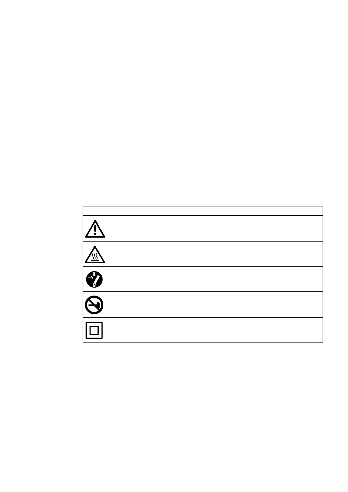
Warning symbols on the device
Symbol
Meaning
This device left the factory in good working condition. In order to maintain this status and to
ensure safe operation of the device, observe these instructions and all the specifications
relevant to safety.
Observe the information and symbols on the device. Do not remove any information or
symbols from the device. Always keep the information and symbols in a completely legible
state.
Consult operating instructions
Hot surface
Isolate the device from power using a circuit-breaker
Protect the device from shocks (otherwise the specified
degree of protection is not guaranteed)
Protective insulation; device in protection class II
SIPART PS2 with and without HART
Operating Instructions, 10/2013, A5E00074631-11
13

Safety information
2.1.2
Laws and directives
See also
2.1.3
Conformity with European directives
Electromagnetic
Compatibility EMC
2004/108/EC
Directive of the Euro
approximation of the laws of the Member States relating to
electromagnetic compatibility and repealing Directive
89/336/EEC.
Atmosphère explosible
ATEX
94/9/EC
Directive of the European Parliament and the Council
approximation of the laws of the Member States concerning
equipment and protective systems intended for use in
potentially explosive atmospheres.
2.1 Requirements for safe use
Observe the test certification, provisions and laws applicable in your country during
connection, assembly and operation. These include, for example:
● National Electrical Code (NEC - NFPA 70) (USA)
● Canadian Electrical Code (CEC) (Canada)
Further provisions for hazardous area applications are for example:
● IEC 60079-14 (international)
● EN 60079-14 (EC)
Certificates (http://www.siemens.com/processinstrumentation/certificates)
The CE marking on the device shows conformity with the regulations of the following
European guidelines:
pean Parliament and of the Council on the
on the
The applied standards can be found in the EC conformity declaration of the device.
SIPART PS2 with and without HART
14 Operating Instructions, 10/2013, A5E00074631-11

Safety information
2.2
Improper device modifications
WARNING
Improper device modifications
2.3
Requirements for special applications
Note
Operation under special ambient conditions
We highly recommend that you contact your Siemens representative or our application
department before you operate the device under special amb
encountered in nuclear power plants or when the device is used for research and
development purposes.
2.2 Improper device modifications
Danger to personnel, system and environment can result from modifications to the device,
particularly in hazardous areas.
• Only carry out modifications that are described in the instructions for the device. Failure
to observe this requirement cancels the manufacturer's warranty and the product
approvals.
Due to the large number of possible applications, each detail of the described device
versions for each possible scenario during commissioning, operation, maintenance or
operation in systems cannot be considered in the instructions. If you need additional
information not covered by these instructions, contact your local Siemens office or company
representative.
ient conditions as can be
SIPART PS2 with and without HART
Operating Instructions, 10/2013, A5E00074631-11
15
Safety information
2.4
Use in hazardous areas
Qualified personnel for hazardous area applications
WARNING
Unsuitable device for the hazardous area
WARNING
Loss of safety of device with type of protection "Intrinsic safety Ex i"
2.4 Use in hazardous areas
Persons who install, connect, commission, operate, and service the device in a hazardous
area must have the following specific qualifications:
● They are authorized, trained or instructed in operating and maintaining devices and
systems according to the safety regulations for electrical circuits, high pressures,
aggressive, and hazardous media.
● They are authorized, trained, or instructed in carrying out work on electrical circuits for
hazardous systems.
● They are trained or instructed in maintenance and use of appropriate safety equipment
according to the pertinent safety regulations.
Danger of explosion.
• Only use equipment that is approved for use in the intended hazardous area and
labelled accordingly.
If the device has already been operated in non-intrinsically safe circuits or the electrical
specifications have not been observed, the safety of the device is no longer ensured for use
in hazardous areas. There is a danger of explosion.
• Connect the device with type of protection "Intrinsic safety" solely to an intrinsically safe
circuit.
• Observe the specifications for the electrical data on the certificate and in Chapter
"Technical data (Page 235)".
SIPART PS2 with and without HART
16 Operating Instructions, 10/2013, A5E00074631-11

3
3.1
Function
● The electropneumatic positioner, in combination with the drive, forms a regulation system.
The current position of the actuator is detected using a potentiometer and returned as the
actual value x. The setpoint and actual value are output simultaneously on the display.
● The setpoint w forms a current applied to the positioner, which in two-wire mode is also
used to power the positioner. In 3- and 4-wire mode, power is supplied through a 24-V
power input.
● The positioner works as a predictive five-point positioner, through whose output value
±Δy the integrated valves can be controlled by pulse length modulation.
● These positioning signals cause pressure changes in the drive chamber(s) and thus a
repositioning of the drive until the regulation deviation returns to zero.
● Using three buttons and the display with the enclosure cover removed, operation (manual
mode) and configuration (structuring, initialization, and parameter assignment) can be
performed.
● By default, the basic unit has a binary input (BE1). This binary input can be individually
configured and used e.g. to block the control levels.
● To be able to use the positioner in a variety of mechanically different rotational and linear
actuators, it has a friction clutch and a switchable gear.
SIPART PS2 with and without HART
Operating Instructions, 10/2013, A5E00074631-11
17

Description
3.2
Structure
3.2.1
Overview of structure
3.2 Structure
The following sections describe the mechanical and electrical structure, components, and
principle functionality of the positioner.
The positioner is available in the following configurations:
● SIPART PS2 without explosion protection in stainless steel, aluminum or Makrolon
enclosure
● SIPART PS2 with Ex i protection in stainless steel, aluminum or Makrolon enclosure
● SIPART PS2 with Ex d protection in flameproof aluminum enclosure
The positioner is used to move and control pneumatic actuators. The positioner works
electropneumatically, using compressed air as auxiliary power. The positioner is used to
control valves, for example, with:
● Linear actuator
● Part-turn actuator VDI/VDE 3845
Various add-on extensions are available for linear actuators:
● IEC 60534-6-1 (NAMUR)
● Integrated addition to ARCA
● Integrated addition to SAMSON in non-flameproof aluminum enclosure
SIPART PS2 with and without HART
18 Operating Instructions, 10/2013, A5E00074631-11
Description
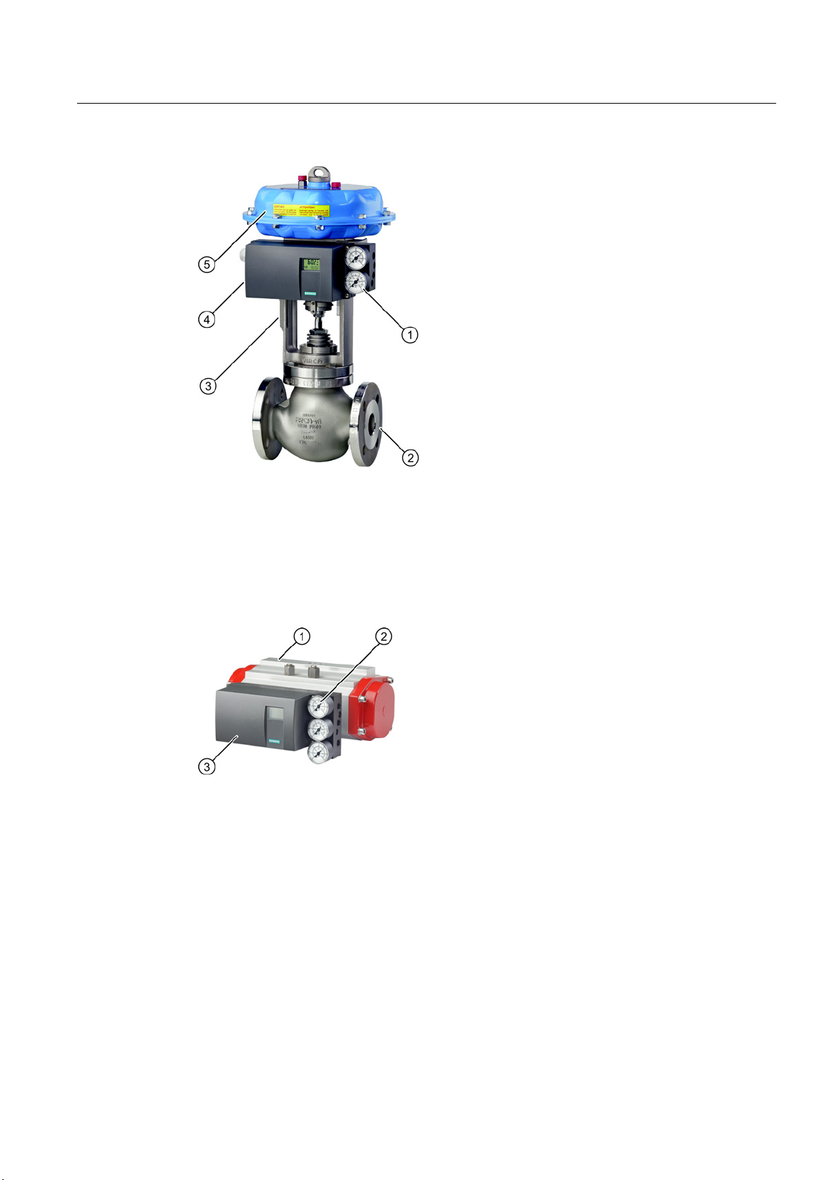
①
Pressure gauge block, single-acting
②
Valve
③
Yoke / actuator yoke
④
Single-acting positioner in non-flameproof aluminum enclosure
⑤
Actuator
①
Part-turn actuator
②
Pressure gauge block, double-acting
③
Double-acting positioner in macrolon enclosure
3.2 Structure
Figure 3-1 Positioner attached to a single-acting linear actuator
Figure 3-2 Positioner attached to double-acting part-turn actuator
SIPART PS2 with and without HART
Operating Instructions, 10/2013, A5E00074631-11
19
Description
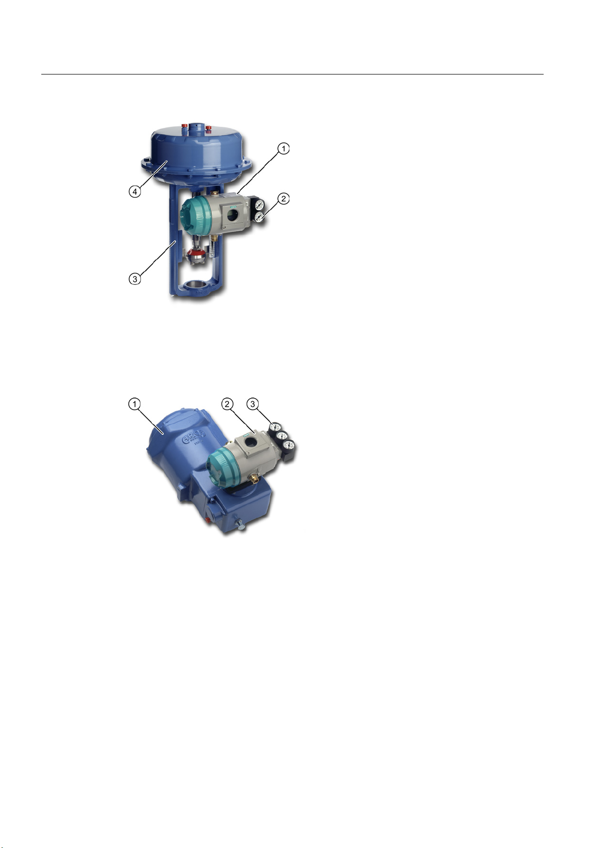
①
Single-acting positioner in flameproof aluminum enclosure
②
Pressure gauge block, single-acting
③
Yoke / actuator yoke
④
Actuator
①
Part-turn actuator
②
Double-acting positioner in flameproof aluminum enclosure
③
Pressure gauge block, double-acting
3.2 Structure
Figure 3-3 Positioner in flameproof aluminum enclosure attached to linear actuator
Figure 3-4 Positioner in flameproof aluminum enclosure attached to part-turn actuator
SIPART PS2 with and without HART
20 Operating Instructions, 10/2013, A5E00074631-11
Description
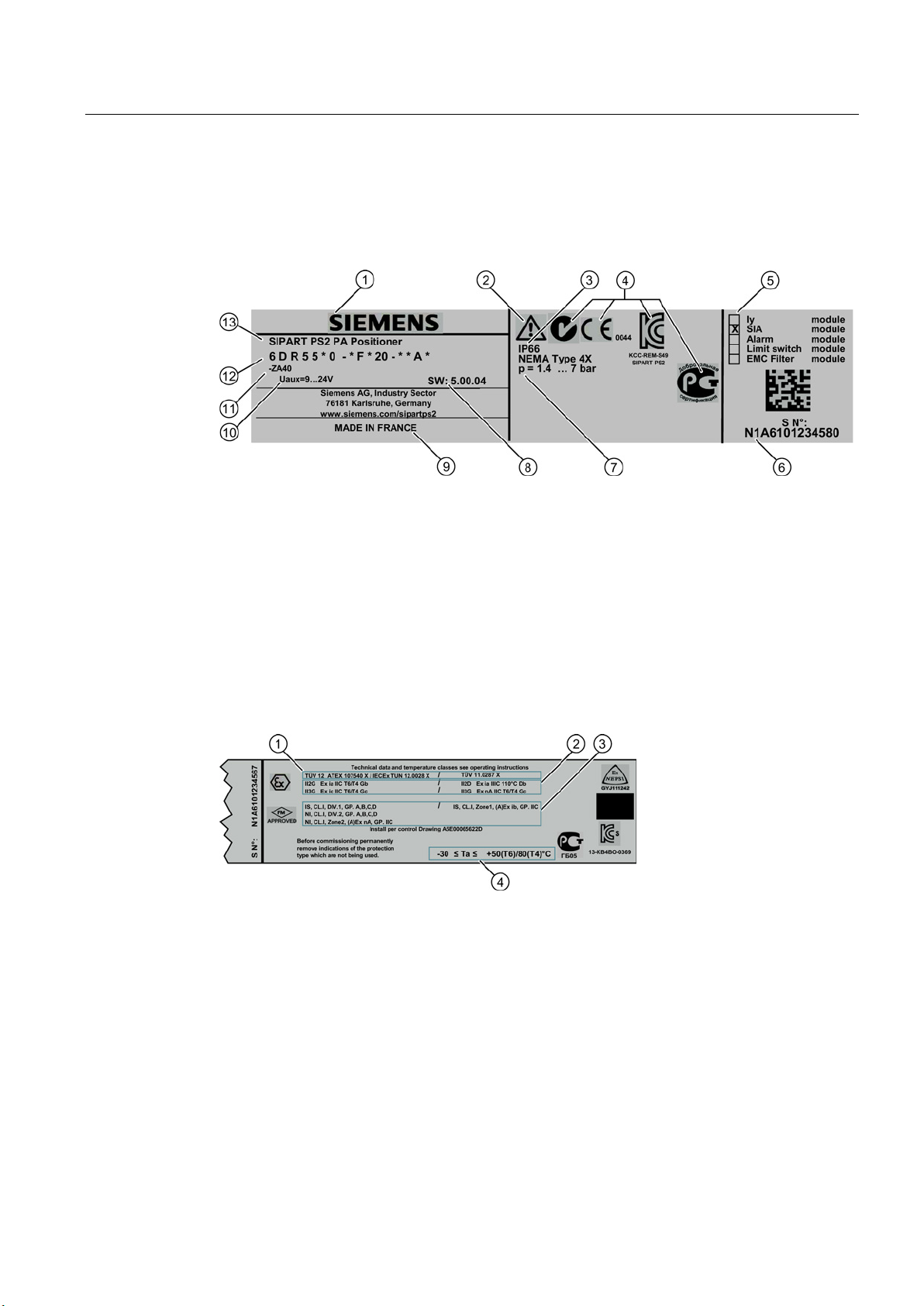
3.2.2
Nameplate layout
Design of the nameplate
①
Manufacturer
⑧
Software version
②
Consult operating instructions
⑨
Place of manufacture
③
Safety class
⑩
Auxiliary power
④
Conformity with country-specific directives
⑪
Ordering supplement (Order code)
⑤
Built-in option module
⑫
Order no.
⑥
Manufacturer serial number
⑬
Product name
⑦
Auxiliary power (air supply)
Layout of Ex nameplate
①
Approvals
③
FM/CSA marking for hazardous area
②
④
temperature class
3.2 Structure
Figure 3-5 Nameplate_design, example
ATEX/IECEX marking for hazardous area
Figure 3-6 Layout of Ex nameplate
Permissible ambient temperature for the
hazardous area of the corresponding
SIPART PS2 with and without HART
Operating Instructions, 10/2013, A5E00074631-11
21

Description
Explanation of Ex information
①
④
(temperature class)
②
Type of protection
⑤
Device protection level
③
Group (gas, dust)
3.2 Structure
Category for operating range
Figure 3-7 Explanation of Ex information
Maximum surface temperature
SIPART PS2 with and without HART
22 Operating Instructions, 10/2013, A5E00074631-11
Description
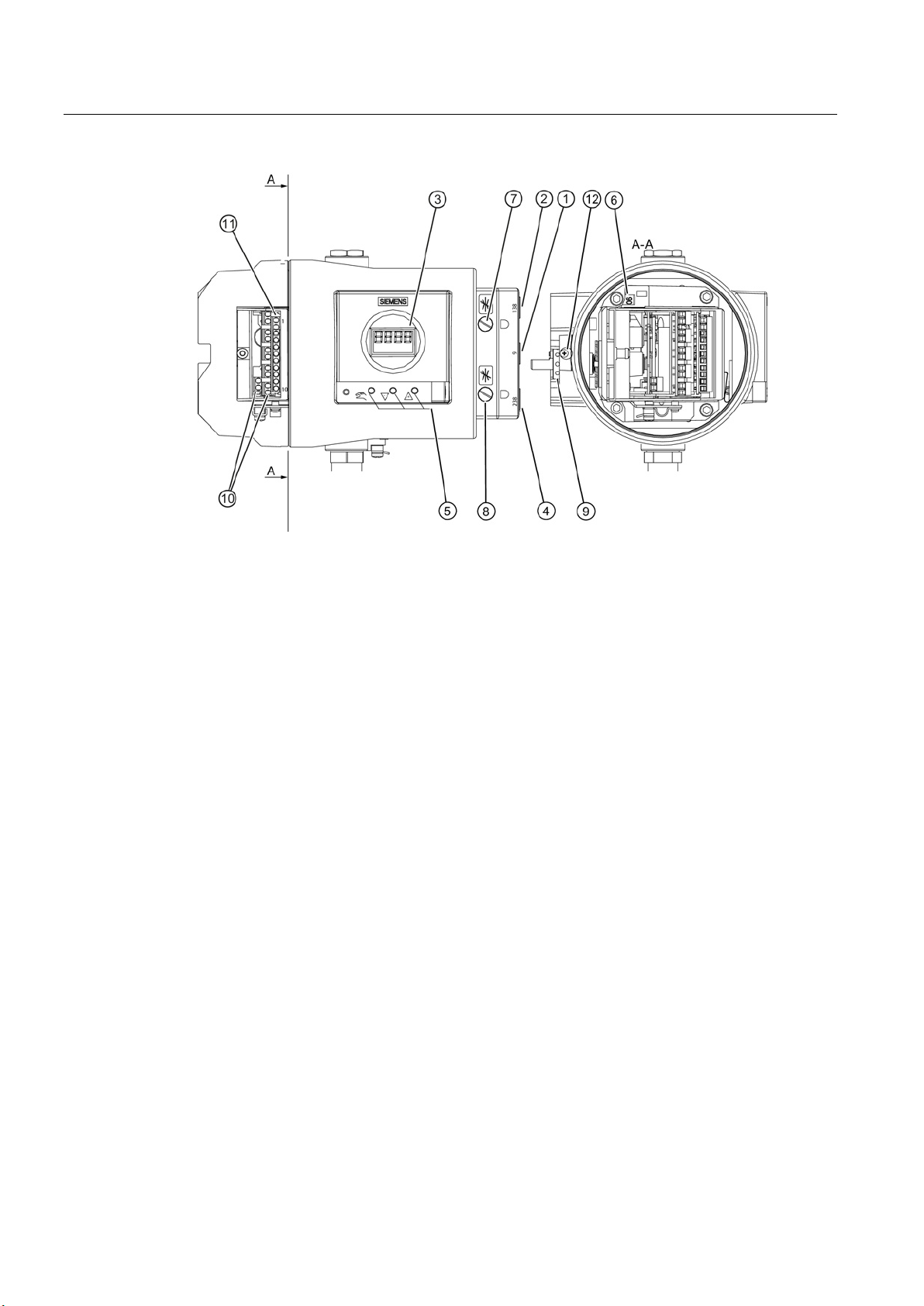
3.3
Device components
3.3.1
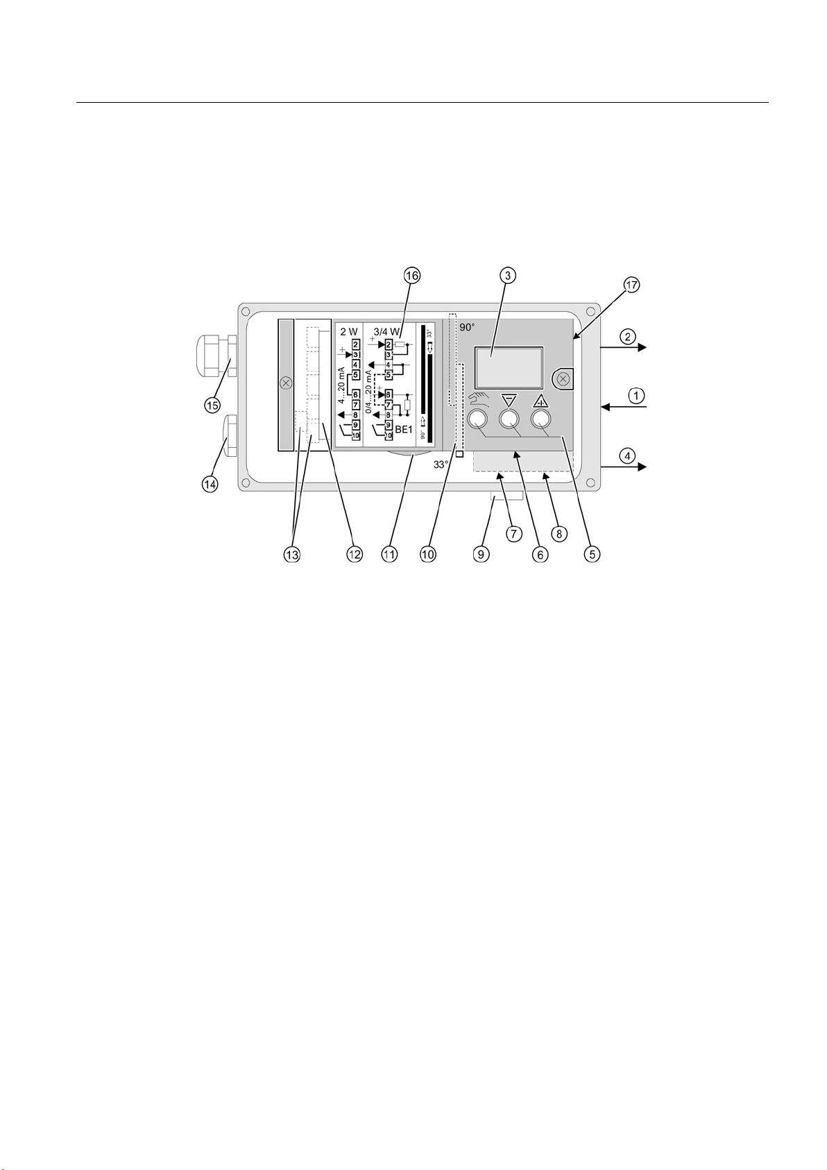
Overview of device components
①
Input: Supply air
⑩
Transmission ratio selector
②
Output: Actuating pressure Y1
⑪
Friction clutch adjustment wheel
③
Display
⑫
Basic electronics
④
Output: Actuating pressure Y2
⑬
Connecting terminals of option modules
⑤
Buttons
⑭
Dummy plug
⑥
Restrictor Y1 for single-acting actuators
⑮
Cable gland
⑦
Restrictor Y1 for double-acting actuators
⑯
Wiring diagram on module cover
⑧
Restrictor Y2 for double-acting actuators
⑰
Purging air selector
⑨
Exhaust air outlet with a sound absorber
3.3 Device components
Figure 3-8 View of basic positioner with cover open
SIPART PS2 with and without HART
Operating Instructions, 10/2013, A5E00074631-11
23
Description
①
Input: Supply air
⑦
Restrictor Y1
②
Output: Actuating pressure Y1
⑧
Restrictor Y2 1)
③
Display
⑨
Friction clutch adjustment wheel
④
Output: Actuating pressure Y2 1)
⑩
Connecting terminals of option modules
⑤
Buttons
⑪
Connecting terminals of basic device
⑥
Transmission ratio selector 2)
⑫
Safety catch
for double-acting actuators
only possible when positioner is open
3.3 Device components
1)
2)
Figure 3-9 View of positioner in flameproof enclosure
SIPART PS2 with and without HART
24 Operating Instructions, 10/2013, A5E00074631-11

Description
3.3.2
Basic electronics
3.3 Device components
Figure 3-10 Basic electronics
The basic electronics contains:
● CPU
● Memory
● Analog-to-digital converter
● Display
● Buttons
● Terminal strips to connect the option module to the basic electronics
SIPART PS2 with and without HART
Operating Instructions, 10/2013, A5E00074631-11
25

Description
3.4
Mode of operation
Control loop
N
See also
3.4 Mode of operation
The electropneumatic positioner forms a control loop with the pneumatic drive:
● The actual value x represents the position of the drive spindle for linear actuators or the
position of the drive shaft for part-turn actuators.
● The control value w represents the positioning current of a closed-loop controller or a
manual control station from 0/4 to 20 mA.
The lifting or rotary movement of the actuator is transferred to a potentiometer using suitable
attachments, positioner axis and a backlash-free, switchable gear drive, and then to the
analog input of the microcontroller. The current position can also be forwarded to the
positioner using an external sensor. A
record the lifting or rotation angle directly on the actuator.
The microcontroller:
● Corrects the angle error of the shaft pick-up if necessary.
on-Contacting Position Sensor (NCS) is used to
● Compares the potentiometer voltage as actual value x with the setpoint w. The setpoint w
is connected to terminals 6 and 7 by means of PROFIBUS communication.
● Calculates the manipulated variable increments ±∆y.
The piezo-controlled inlet or exhaust air valve is opened depending on the magnitude and
direction of the control deviation (x-w). The actuator volume integrates the controller
increment for the actuating pressure y which is proportional to the drive rod or the drive
shaft. This controller increment change the actuating pressure until the control deviation
becomes zero.
Pneumatic actuators are available in single and double-acting versions. In a single-acting
version, only one pressure chamber is ventilated and depressurized. The pressure
developed works against a spring. In a double-acting version, two pressure chambers work
against each other. Ventilating the volume of one chamber simultaneously depressurizes the
volume of the other.
Block circuit diagram for signal-acting or dual-acting drives (Page 28)
SIPART PS2 with and without HART
26 Operating Instructions, 10/2013, A5E00074631-11
Description
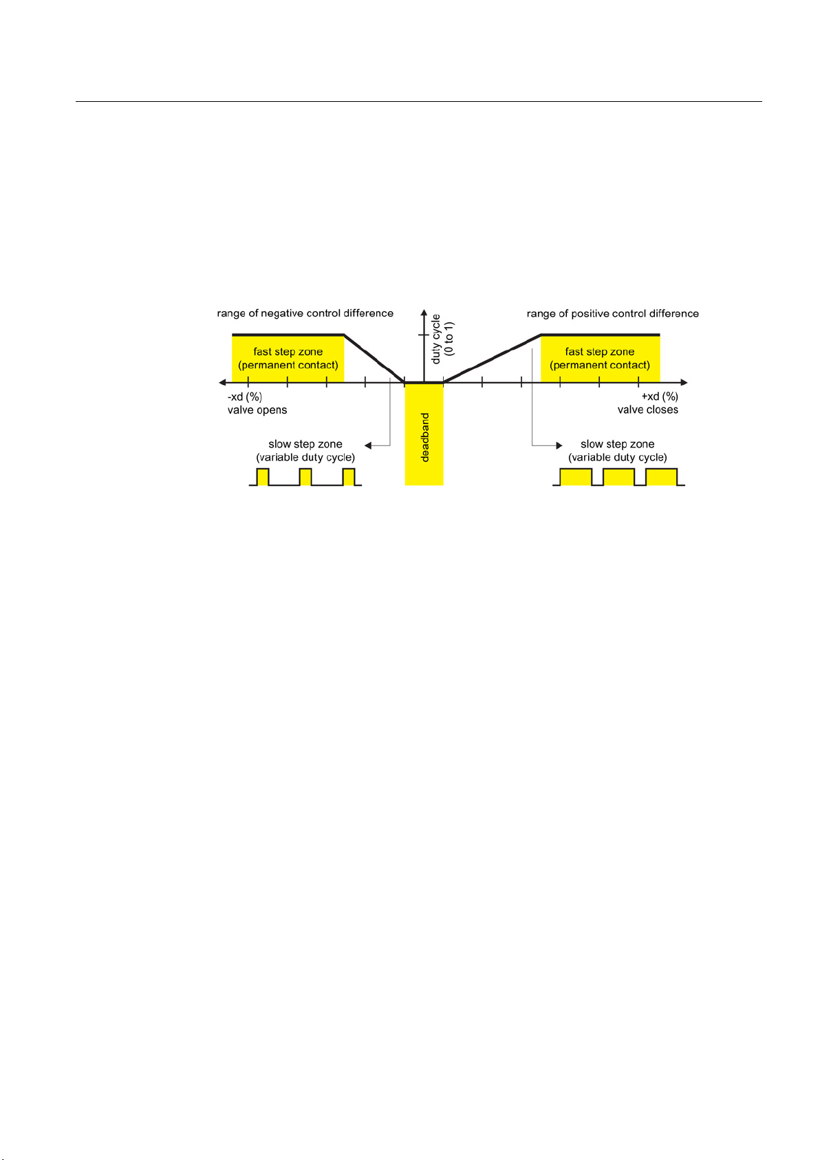
3.4.1
Control algorithm
3.4 Mode of operation
The control algorithm is an adaptive, predictive five-point controller.
In case of large control deviations, the valves are controlled using permanent contact. This
takes place in the so-called fast step zone.
In case of medium control deviations, valves are controlled using pulse-length modulated
pulses. This takes place in the so-called slow step zone.
Figure 3-11 Functional principle of five-point controller
Small control deviations do not send control pulses in the zone. This takes place in the socalled adaptive deadband. The deadband adaptation and the continuous adaptation of
minimum pulse lengths in the automatic mode ensure the best possible control accuracy with
the smallest number of operating cycles. The start parameters are determined during the
initialization phase and stored in the non-volatile memory. The most important start
parameters are:
● The real actuator travel with mechanical end stops
● Actuating times
● The deadband size
The number of fault messages, changes in direction and the stroke number are continuously
determined during operation and saved after every 15 minutes. You can read and document
these parameters using communication programs such as PDM and AMS. By comparing the
old values with the current ones, you can draw conclusions about the wear and tear of the
control valve. You can use the diagnostics function for this.
SIPART PS2 with and without HART
Operating Instructions, 10/2013, A5E00074631-11
27
Description
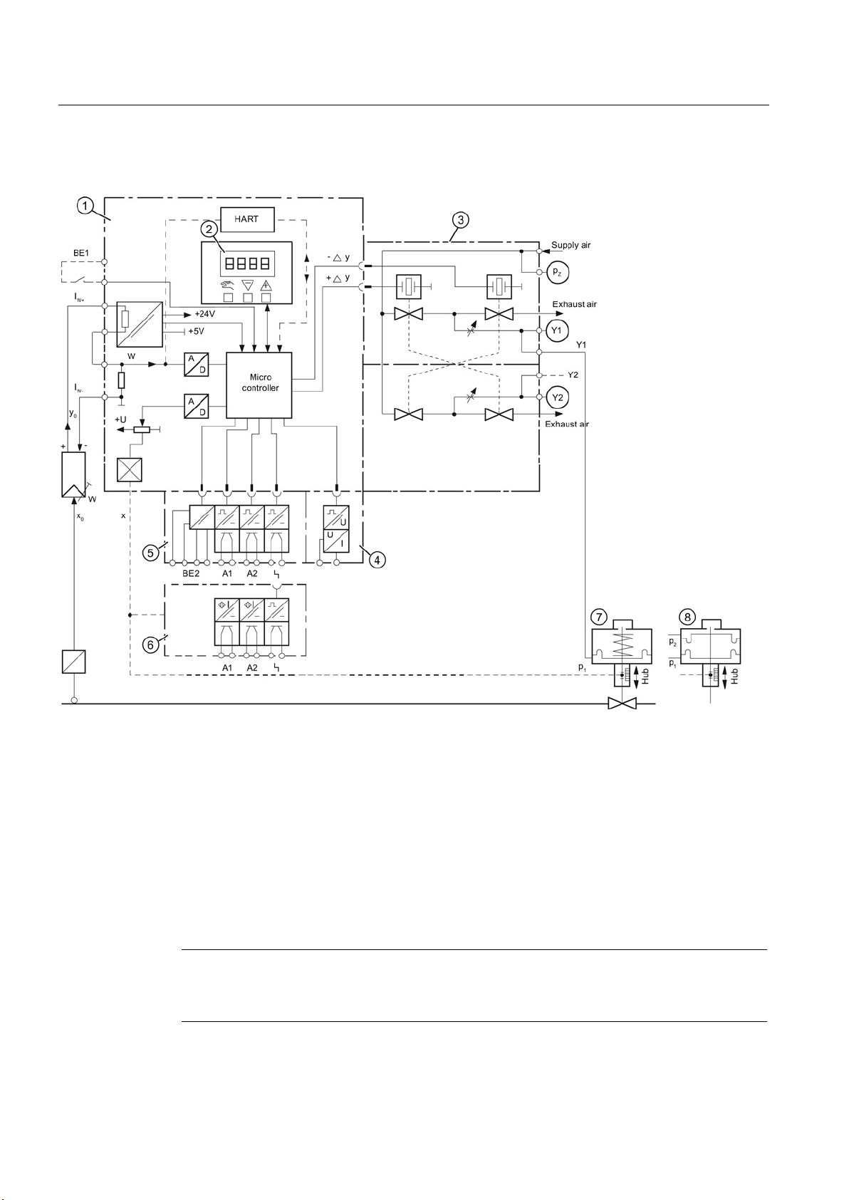
3.4.2
Block circuit diagram for signal-acting or dual-acting drives
①
Basic electronics with microcontroller and input circuit
②
Control pad with display and buttons
③
Single-acting (6DR5.1.) or double-acting (6DR5.2.) pneumatic block
④
Iy module for positioner
⑤
Alarm module for three alarm outputs and one binary input
⑥
SIA module (slot initiator alarm module)
⑦
Spring-loaded pneumatic positioning drive (single-acting)
⑧
Pneumatic actuator (double-acting)
Note
Alarm module and SIA module
Alarm module
3.4 Mode of operation
Figure 3-12 Block circuit diagram for the electropneumatic positioner, functional diagram
⑥ and SIA module ⑦ can only be alternatively used.
SIPART PS2 with and without HART
28 Operating Instructions, 10/2013, A5E00074631-11
 Loading...