

Siemens SIPART PS2 Operating Instructions Manual
SIPART
EleNtropneumatiFSRVLWLRQHU
SIPART PS2 with and without HART
Edition
/201
Operating Instructions
Answers for industry.


SIPART
Electropneumatic positioners
SIPART PS2 with and without HART
6DR50..
6DR51..
6DR52..
6DR53..
Introduction
1
Operating Instructions
Safety information
Description
Installing/mounting
Connection
Operating
Commissioning
Functional safety
Parameter assignment
Alarm, error, and system
messages
Service and maintenance
2
3
4
5
6
7
8
9
10
11
Technical data
Dimension drawings
Spare parts / accessories /
scope of delivery
Appendix
External position detection
with NCS or external position
detection system
Pressure gauge block
Sealing plug / thread adapter
Booster
Positioner with remote
control electronics
12
13
14
A
B
C
D
E
F
05/2017
A5E00074631-AC
Abbreviations
G

Legal information
Warning notice system
This manual contains notices you have to observe in order to ensure your personal safety, as well as to prevent
damage to property. The notices referring to your personal safety are highlighted in the manual by a safety alert
symbol, notices referring only to property damage have no safety alert symbol. These notices shown below are
graded according to the degree of danger.
DANGER
indicates that death or severe personal injury will result if proper precautions are not taken.
WARNING
indicates that death or severe personal injury may result if proper precautions are not taken.
CAUTION
indicates that minor personal injury can result if proper precautions are not taken.
NOTICE
indicates that property damage can result if proper precautions are not taken.
If more than one degree of danger is present, the warning notice representing the highest degree of danger will be
used. A notice warning of injury to persons with a safety alert symbol may also include a warning relating to property
damage.
Qualified Personnel
The product/system described in this documentation may be operated only by personnel qualified for the specific
task in accordance with the relevant documentation, in particular its warning notices and safety instructions. Qualified
personnel are those who, based on their training and experience, are capable of identifying risks and avoiding
potential hazards when working with these products/systems.
Proper use of Siemens products
Note the following:
WARNING
Siemens products may only be used for the applications described in the catalog and in the relevant technical
documentation. If products and components from other manufacturers are used, these must be recommended or
approved by Siemens. Proper transport, storage, installation, assembly, commissioning, operation and
maintenance are required to ensure that the products operate safely and without any problems. The permissible
ambient conditions must be complied with. The information in the relevant documentation must be observed.
Trademarks
All names identified by ® are registered trademarks of Siemens AG. The remaining trademarks in this publication
may be trademarks whose use by third parties for their own purposes could violate the rights of the owner.
Disclaimer of Liability
We have reviewed the contents of this publication to ensure consistency with the hardware and software described.
Since variance cannot be precluded entirely, we cannot guarantee full consistency. However, the information in
this publication is reviewed regularly and any necessary corrections are included in subsequent editions.
Siemens AG
Division Process Industries and Drives
Postfach 48 48
90026 NÜRNBERG
GERMANY
Document order number: A5E00074631
Ⓟ 06/2017 Subject to change
Copyright © Siemens AG 2017.
All rights reserved

Table of contents
1 Introduction.................................................................................................................................................13
1.1 Purpose of this documentation...............................................................................................13
1.2 Product compatibility..............................................................................................................13
1.3 Document history...................................................................................................................14
1.4 Checking the consignment.....................................................................................................15
1.5 Security information...............................................................................................................15
1.6 Transportation and storage....................................................................................................16
1.7 Notes on warranty..................................................................................................................16
2 Safety information.......................................................................................................................................17
2.1 Precondition for use...............................................................................................................17
2.2 Warning symbols on the device.............................................................................................17
2.3 Laws and directives................................................................................................................17
2.4 Conformity with European directives......................................................................................18
2.5 Improper device modifications...............................................................................................18
2.6 Requirements for special applications...................................................................................18
2.7 Use in hazardous areas.........................................................................................................19
3 Description..................................................................................................................................................21
3.1 Function.................................................................................................................................21
3.2 Structure.................................................................................................................................21
3.2.1 Overview of structure.............................................................................................................21
3.2.2 Nameplate layout...................................................................................................................24
3.2.3 Explanation of Ex information................................................................................................25
3.3 Device components................................................................................................................26
3.3.1 Overview of device components............................................................................................26
3.3.2 Basic electronics....................................................................................................................27
3.4 Mode of operation..................................................................................................................28
3.4.1 Block circuit diagram for single-acting or double-acting actuators.........................................30
3.4.2 Mode of operation of the HART function................................................................................31
3.4.3 HART system configuration...................................................................................................31
3.4.4 SIMATIC PDM........................................................................................................................32
4 Installing/mounting......................................................................................................................................33
4.1 Basic safety instructions.........................................................................................................33
4.1.1 Proper mounting.....................................................................................................................36
4.2 Mounting the linear actuator...................................................................................................36
SIPART PS2 with and without HART
Operating Instructions, 05/2017, A5E00074631-AC 5

Table of contents
4.3 Mounting the part-turn actuator..............................................................................................42
4.4 Using the positioner in a humid environment.........................................................................47
4.5 Positioners subjected to fast acceleration or strong vibration................................................48
4.6 Installing option modules........................................................................................................51
4.6.1 General information on installing option modules..................................................................51
4.6.1.1 Installing optional modules in the standard and intrinsically safe version..............................51
4.6.1.2 Installing the optional modules in the "flameproof enclosure" version...................................54
4.6.2 Installing the position feedback module.................................................................................58
4.6.3 Installing the alarm module....................................................................................................59
4.6.4 Installing the slit initiator alarm module (SIA).........................................................................60
4.6.5 Installing the mechanical limit switch module.........................................................................63
4.6.6 Installing the internal NCS module 6DR4004-5L/-5LE...........................................................67
4.6.7 EMC filter module...................................................................................................................69
5 Connection.................................................................................................................................................73
5.1 Basic safety instructions.........................................................................................................73
5.2 Electrical wiring......................................................................................................................77
5.2.1 Connection diagram split range.............................................................................................79
5.2.2 Option modules......................................................................................................................80
5.2.2.1 Alarm modules 6DR4004-6A and -8A....................................................................................80
5.2.2.2 Position feedback modules 6DR4004-6J and -8J..................................................................81
5.2.2.3 SIA modules 6DR4004-6G and -8G.......................................................................................81
5.2.2.4 Mechanical limit switch modules 6DR4004-6K and -8K.........................................................82
5.2.3 Option device version M12 connector....................................................................................84
5.2.3.1 M12 connector in the basic device.........................................................................................85
5.2.3.2 M12 connector for connection of the outputs of the alarm module 6DR4004-6A / -8A (-
Z D55)....................................................................................................................................85
5.2.3.3 M12 connector for connecting the outputs of the position feedback module 6DR4004-6J /
8J (-Z D53).............................................................................................................................86
5.2.3.4 M12 connector for connecting the external position detection system (-Z D54)....................86
5.2.3.5 M12 connector for connecting the outputs of the SIA module 6DR4004-6G /-8G (-Z D56)......86
5.3 Pneumatic connection............................................................................................................87
5.3.1 Pneumatic connection for 6DR5..0/1/2/3...............................................................................87
5.3.2 Integrated pneumatic connection...........................................................................................87
5.3.3 Pneumatic connection for 6DR5..5-0E...................................................................................88
5.3.4 Reaction to failure of auxiliary powers...................................................................................89
5.3.5 Pneumatic connection............................................................................................................92
5.4 Restrictors..............................................................................................................................93
6 Operating....................................................................................................................................................95
6.1 Operating elements................................................................................................................95
6.1.1 Display...................................................................................................................................95
6.1.2 Buttons...................................................................................................................................96
6.1.3 Firmware version ...................................................................................................................97
6.2 Operating modes....................................................................................................................98
6.2.1 Overview of operating modes................................................................................................98
6.2.2 Changing the operating mode................................................................................................99
6.2.3 Overview of configuration.....................................................................................................100
SIPART PS2 with and without HART
6 Operating Instructions, 05/2017, A5E00074631-AC

Table of contents
6.2.4 Description of operating modes...........................................................................................100
6.2.5 Optimization of controller data.............................................................................................102
7 Commissioning.........................................................................................................................................105
7.1 Basic safety instructions.......................................................................................................105
7.2 Overview..............................................................................................................................107
7.3 Sequence of automatic initialization.....................................................................................108
7.4 Purge air switching...............................................................................................................114
7.5 Commissioning linear actuators...........................................................................................115
7.5.1 Preparing linear actuators for commissioning......................................................................115
7.5.2 Automatic initialization of linear actuators............................................................................116
7.5.3 Manual initialization of linear actuators................................................................................119
7.6 Commissioning part-turn actuators......................................................................................122
7.6.1 Preparing part-turn actuators for commissioning.................................................................122
7.6.2 Automatic initialization of part-turn actuators.......................................................................123
7.6.3 Manual initialization of part-turn actuators...........................................................................125
7.7 Device replacement.............................................................................................................128
8 Functional safety......................................................................................................................................131
8.1 Range of applications for functional safety..........................................................................131
8.2 Safety function.....................................................................................................................131
8.3 Safety Integrity Level (SIL)...................................................................................................132
8.4 Settings................................................................................................................................133
8.5 Safety characteristics...........................................................................................................134
8.6 Maintenance/check..............................................................................................................135
9 Parameter assignment.............................................................................................................................137
9.1 Introduction to parameter assignment section.....................................................................137
9.2 Configuration schematic for parameter operating principle..................................................138
9.3 Tabular overview of the parameters.....................................................................................139
9.3.1 Overview of initialization parameters 1 to 5.........................................................................139
9.3.2 Overview of application parameters 6 to 52.........................................................................140
9.3.3 Overview of advanced diagnostics parameters A to P.........................................................143
9.4 Description of parameters....................................................................................................147
9.4.1 Initialization parameters 1 to 5.............................................................................................147
9.4.1.1 '1.YFCT' type of actuator......................................................................................................147
9.4.1.2 '2.YAGL' Rated angle of rotation of feedback......................................................................148
9.4.1.3 '3.YWAY' Range of stroke....................................................................................................149
9.4.1.4 '4.INITA' Initialization (automatically)...................................................................................150
9.4.1.5 '5.INITM' Initialization (manual)............................................................................................150
9.4.2 Application parameters 6 to 52............................................................................................150
9.4.2.1 '6.SCUR' Current range of setpoint......................................................................................150
9.4.2.2 '7.SDIR' Setpoint direction...................................................................................................151
9.4.2.3 '8.SPRA' Setpoint split range start / '9.SPRE' Setpoint split range start end.......................151
9.4.2.4 '10.TSUP' Setpoint ramp UP / '11.TSDO' Setpoint ramp DOWN.........................................152
SIPART PS2 with and without HART
Operating Instructions, 05/2017, A5E00074631-AC 7

Table of contents
9.4.2.5 '12.SFCT' Setpoint function..................................................................................................153
9.4.2.6 '13.SL0' ... '33.SL20' Setpoint turning point..........................................................................153
9.4.2.7 '34.DEBA' Deadband of closed-loop controller....................................................................154
9.4.2.8 '35.YA' Start of manipulated variable limit / '36.YE' End of manipulated variable limit.........155
9.4.2.9 '37.YNRM' Standardization of manipulated variable............................................................155
9.4.2.10 '38.YDIR' Direction of manipulated variable for display and position feedback...................157
9.4.2.11 '39.YCLS' Tight closing/fast closing with manipulated variable............................................157
9.4.2.12 '40.YCDO' Value for tight closing/fast closing Down............................................................158
9.4.2.13 '41.YCUP' Value for tight closing/fast closing Up.................................................................158
9.4.2.14 '42.BIN1' / '43.BIN2' Function binary input...........................................................................159
9.4.2.15 '44.AFCT' Alarm function.....................................................................................................160
9.4.2.16 '45.A1' / '46.A2' Response threshold of alarm......................................................................162
9.4.2.17 '47.\\FCT' Function for fault message output.......................................................................162
9.4.2.18 '48.\\TIM' Monitoring time for setting of fault message 'Control deviation'...........................163
9.4.2.19 '49.\\LIM' Response threshold of fault message 'Control deviation'.....................................163
9.4.2.20 '50.PRST' Preset..................................................................................................................164
9.4.2.21 '51.PNEUM' Pneumatics type..............................................................................................164
9.4.2.22 '52.XDIAG' Activating for extended diagnostics...................................................................166
9.4.3 Extended diagnostics parameters A to P.............................................................................167
9.4.3.1 Partial stroke test 'A.\\PST'...................................................................................................167
9.4.3.2 Monitoring of dynamic control valve behavior 'b.\\DEVI'......................................................172
9.4.3.3 Monitoring/compensation of pneumatic leakage 'C.\\LEAK'.................................................174
9.4.3.4 Monitoring of stiction (slipstick) 'd.\\STIC'.............................................................................177
9.4.3.5 Monitoring of deadband 'E.\\DEBA'......................................................................................179
9.4.3.6 Monitoring of lower endstop 'F.\\ZERO'...............................................................................180
9.4.3.7 Monitoring the upper endstop 'G.\\OPEN'............................................................................181
9.4.3.8 Monitoring the low limit temperature 'H.\\TMIN'...................................................................183
9.4.3.9 Monitoring the high limit temperature 'J.\\TMAX'..................................................................185
9.4.3.10 Monitoring of number of total strokes 'L.\\STRK'..................................................................186
9.4.3.11 Monitoring of number of changes in direction 'O.\\DCHG'...................................................188
9.4.3.12 Monitoring the position average value 'P.\\PAVG'................................................................189
10 Alarm, error, and system messages.........................................................................................................193
10.1 Output of system messages in the display...........................................................................193
10.1.1 System messages before initialization.................................................................................193
10.1.2 System messages during initialization.................................................................................193
10.1.3 System messages when exiting the Configuration mode....................................................196
10.1.4 System messages during operation.....................................................................................196
10.2 Diagnostics...........................................................................................................................198
10.2.1 Display of diagnostics values...............................................................................................198
10.2.2 Saving the diagnostics values..............................................................................................198
10.2.3 Overview of diagnostics values............................................................................................199
10.2.4 Meaning of the diagnostics values.......................................................................................201
10.2.4.1 Diagnostic value '1.STRKS - Number of total strokes'.........................................................201
10.2.4.2 Diagnostic value '2.CHDIR - Number of changes in direction'.............................................201
10.2.4.3 Diagnostic value '3.\\CNT - Number of fault messages'.......................................................201
10.2.4.4 Diagnostic value '4.A1CNT - Number of alarms 1' / '5.A2CNT - Number of alarms 2'.........201
10.2.4.5 Diagnostic value '6.HOURS - Number of operating hours'..................................................201
10.2.4.6 Diagnostic value '7.HOURR - Resettable operating hours counter'.....................................202
10.2.4.7 Diagnostic value '8.WAY - Determined travel'......................................................................202
10.2.4.8 Diagnostic value '9.TUP - Travel time up' / '10.TDOWN - Travel time down' ......................202
10.2.4.9 Diagnostic value '11.LEAK - Leakage test'..........................................................................202
SIPART PS2 with and without HART
8 Operating Instructions, 05/2017, A5E00074631-AC

Table of contents
10.2.4.10 Diagnostic value '12.PST - Monitoring of partial stroke test'................................................203
10.2.4.11 Diagnostic value '13.PRPST' - Time since last partial stroke test'.......................................204
10.2.4.12 Diagnostic value '14.NXPST - Time until next partial stroke test'........................................205
10.2.4.13 Diagnostics value '15.DEVI - Dynamic control valve behavior'............................................205
10.2.4.14 Diagnostic value '16.ONLK - Pneumatic leakage'................................................................205
10.2.4.15 Diagnostic value '17.STIC - Stiction (slipstick)'....................................................................205
10.2.4.16 Diagnostic value '18.ZERO - Lower endstop'.......................................................................206
10.2.4.17 Diagnostic value '19.OPEN - Upper endstop'......................................................................206
10.2.4.18 Diagnostic value '20.PAVG - Average value of position'......................................................206
10.2.4.19 Diagnostic value '21.P0 - Potentiometer value of lower endstop (0%)' / '22.P100 -
Potentiometer value of upper endstop (100%)'....................................................................207
10.2.4.20 Diagnostic value '23.IMPUP - Pulse length up' / '24.IMPDN - Pulse length down' .............208
10.2.4.21 Diagnostic value '25.PAUTP - Pulse interval'.......................................................................209
10.2.4.22 Diagnostic value '26.DBUP - Deadband up' / '27.DBDN - Deadband down'........................209
10.2.4.23 Diagnostic value '28.SSUP - Slow step zone up' / '29.SSDN - Slow step zone down'.... ....209
10.2.4.24 Diagnostic value '30.TEMP - Current temperature'..............................................................210
10.2.4.25 Diagnostic value '31.TMIN - Minimum temperature' / '32.TMAX - Maximum temperature'....210
10.2.4.26 Diagnostic value '33.T1' ... '41.T9' - Number of operating hours in the temperature range
1 to 9....................................................................................................................................210
10.2.4.27 Diagnostic value '42.VENT1' / '43.VENT2' ..........................................................................210
10.2.4.28 Diagnostic value '44.VEN1R' / '45.VEN2R'..........................................................................211
10.2.4.29 Diagnostic value '46.STORE - Save maintenance data'......................................................212
10.2.4.30 Diagnostic value '47.PRUP - Prediction up' / '48.PRDN - Prediction down'.........................212
10.2.4.31 Diagnostic value '49.WT00' ... '56.WT95' - Number of operating hours in the travel range
WT00 to WT95.....................................................................................................................212
10.2.4.32 Diagnostic value '57.LKPUL - Length of the leakage compensation pulse'.........................213
10.2.4.33 Diagnostic value '58.LKPER - Period of the leakage compensation pulse'.........................213
10.2.4.34 Diagnostic value '59.mA - Setpoint current'.........................................................................213
10.3 Online diagnostics................................................................................................................214
10.3.1 Overview of error codes (HART/PA)....................................................................................214
10.3.2 Overview of online diagnostics.............................................................................................216
10.3.3 XDIAG parameter ................................................................................................................216
10.3.4 Meaning of error codes........................................................................................................217
10.3.4.1 1 Remaining control deviation..............................................................................................217
10.3.4.2 2 Device not in "Automatic" mode........................................................................................217
10.3.4.3 3 Binary input BIN1 or BIN2 active.......................................................................................217
10.3.4.4 4 Monitoring the number of total strokes..............................................................................217
10.3.4.5 5 Monitoring the number of changes in direction.................................................................217
10.3.4.6 6 Monitoring the lower endstop / 7 Monitoring the upper endstop.......................................218
10.3.4.7 8 Monitoring deadband........................................................................................................218
10.3.4.8 9 Partial stroke test..............................................................................................................218
10.3.4.9 10 Monitoring of dynamic control valve behavior.................................................................219
10.3.4.10 11 Monitoring/compensation of pneumatic leakage ............................................................219
10.3.4.11 12 Monitoring of stiction (slipstick).......................................................................................219
10.3.4.12 13 Monitoring the lower limit temperature............................................................................219
10.3.4.13 14 Monitoring the upper limit temperature...........................................................................219
10.3.4.14 15 Monitoring the position average value............................................................................219
10.3.4.15 16 Monitoring the plausibility of values for the partial stroke test.........................................219
10.4 Fault correction....................................................................................................................220
10.4.1 Fault identification................................................................................................................220
10.4.2 Remedial measures table 1.................................................................................................221
SIPART PS2 with and without HART
Operating Instructions, 05/2017, A5E00074631-AC 9

Table of contents
10.4.3 Remedial measures table 2.................................................................................................221
10.4.4 Remedial measures table 3.................................................................................................222
10.4.5 Corrective measures Table 4...............................................................................................223
10.4.6 Remedial measures table 5.................................................................................................223
11 Service and maintenance.........................................................................................................................225
11.1 Basic safety instructions.......................................................................................................225
11.2 Cleaning of the screens.......................................................................................................226
11.2.1 Positioners with polycarbonate enclosure 6DR5..0, aluminum enclosure 6DR5..3, and
flameproof aluminum enclosure 6DR5..5.............................................................................226
11.2.2 Positioners with stainless steel enclosure 6DR5..2, flameproof stainless steel enclosure
6DR5..6, and narrow aluminum enclosure 6DR5..1.............................................................227
11.3 Maintenance and repair work...............................................................................................228
11.3.1 Repair/Upgrading.................................................................................................................228
11.4 Replacing the basic electronics with the "Fail in Place" function.........................................228
11.5 Return procedure.................................................................................................................229
11.6 Disposal...............................................................................................................................230
12 Technical data..........................................................................................................................................231
12.1 Rated conditions..................................................................................................................231
12.2 Pneumatic data....................................................................................................................232
12.3 Construction.........................................................................................................................232
12.4 Controller..............................................................................................................................234
12.5 Certificates, approvals, explosion protection........................................................................235
12.6 Electrical data.......................................................................................................................237
12.7 Technical data for natural gas as actuator medium.............................................................239
12.8 Option modules....................................................................................................................240
12.8.1 Alarm module.......................................................................................................................240
12.8.2 Position feedback module....................................................................................................241
12.8.3 SIA module...........................................................................................................................242
12.8.4 Mechanical limit switch module............................................................................................243
12.8.5 EMC filter module.................................................................................................................244
12.8.6 Internal NCS modules 6DR4004-5L and 6DR4004-5LE......................................................245
12.8.7 Other technical specifications..............................................................................................245
13 Dimension drawings.................................................................................................................................247
13.1 Positioner in non-flameproof enclosure................................................................................247
13.2 Terminal strip for positioners with polycarbonate enclosure 6DR5..0 and aluminum
enclosure 6DR5..3...............................................................................................................248
13.3 Positioner with flameproof enclosure...................................................................................249
14 Spare parts / accessories / scope of delivery...........................................................................................251
14.1 Order data............................................................................................................................251
14.2 Overview..............................................................................................................................251
SIPART PS2 with and without HART
10 Operating Instructions, 05/2017, A5E00074631-AC

Table of contents
14.3 Spare parts...........................................................................................................................252
14.4 Scope of delivery of mechanical limit switch module...........................................................253
14.5 Scope of delivery EMC filter module ...................................................................................254
14.6 Accessories..........................................................................................................................255
A Appendix...................................................................................................................................................257
A.1 Certificates...........................................................................................................................257
A.2 Technical support.................................................................................................................257
A.3 QR code label......................................................................................................................258
A.4 Overview of the assignment of the HART variables.............................................................258
B External position detection with NCS or external position detection system............................................259
B.1 Introduction to external position detection............................................................................259
B.2 Non-Contacting Sensor........................................................................................................259
B.2.1 Principle of operation of NCS...............................................................................................259
B.2.2 Mounting the NCS................................................................................................................261
B.2.2.1 Mounting on part-turn actuator ............................................................................................262
B.2.2.2 Mounting on linear actuator up to 14 mm (0.55 inch)...........................................................264
B.2.2.3 Mounting on linear actuator > 14 mm (0.55 inch).................................................................266
B.2.3 Connecting NCS to EMC filter module.................................................................................269
B.2.4 Commissioning of NCS........................................................................................................270
B.2.4.1 Prerequisites / default settings.............................................................................................270
B.2.4.2 Initialization of part-turn actuators........................................................................................271
B.2.4.3 Initializing linear actuators with a stroke range up to 14 mm (0.55 inch).............................271
B.2.4.4 Initializing linear actuators with a stroke range > 14 mm (0.55 inch)...................................271
B.2.5 Technical specifications NCS...............................................................................................271
B.2.6 Dimension drawing of non-contacting system......................................................................273
B.2.7 NCS sensor scope of delivery..............................................................................................274
B.2.7.1 Scope of delivery of NCS for part-turn actuators.................................................................274
B.2.7.2 Scope of delivery of NCS for linear actuators up to 14 mm (0.55 inch) ..............................274
B.2.7.3 Scope of delivery of NCS for linear actuators > 14 mm (0.55 inch) ....................................275
B.3 External position detection system.......................................................................................276
B.3.1 Principle of operation of external position detection system................................................276
B.3.2 Mounting the external position detection system.................................................................276
B.3.3 Connecting the external position detection system to the EMC filter module......................277
B.3.4 Technical specifications of the external position detection system......................................280
B.3.5 Scope of delivery of external position detection system......................................................281
C Pressure gauge block...............................................................................................................................283
D Sealing plug / thread adapter...................................................................................................................285
D.1 Intended use of accessory part............................................................................................285
D.2 Safety instructions for accessory part..................................................................................285
D.3 Technical specifications of accessory part...........................................................................286
D.4 Dimensional drawings of accessory part..............................................................................287
SIPART PS2 with and without HART
Operating Instructions, 05/2017, A5E00074631-AC 11

Table of contents
E Booster.....................................................................................................................................................289
E.1 Operation with boosters.......................................................................................................289
F Positioner with remote control electronics................................................................................................293
F.1 Introduction to remote control electronics............................................................................293
F.2 19" slide-in module...............................................................................................................293
F.2.1 Description 19" slide-in module 4 to 20 mA.........................................................................293
F.2.2 Description 19" slide-in module 4 to 20 mA.........................................................................294
F.2.2.1 Grounding concept 19" slide-in module 4 to 20 mA.............................................................294
F.2.2.2 Electrical connection of 19" slide-in module 4 to 20 mA......................................................296
F.2.3 Technical specifications 19" slide-in module 4 to 20 mA.....................................................298
F.2.4 Dimension drawing 19" slide-in module 4 to 20 mA.............................................................300
F.2.5 Scope of delivery of remote control electronics...................................................................300
F.3 Positioner without basic electronics 6DR5910.....................................................................300
G Abbreviations............................................................................................................................................303
G.1 Abbreviations for positioners................................................................................................303
G.2 Abbreviations for functional safety.......................................................................................304
Glossary...................................................................................................................................................307
Index.........................................................................................................................................................315
SIPART PS2 with and without HART
12 Operating Instructions, 05/2017, A5E00074631-AC

Introduction
1.1 Purpose of this documentation
These instructions contain all information required to commission and use the device. Read
the instructions carefully prior to installation and commissioning. In order to use the device
correctly, first review its principle of operation.
The instructions are aimed at persons mechanically installing the device, connecting it
electronically, configuring the parameters and commissioning it, as well as service and
maintenance engineers.
1.2 Product compatibility
The following table describes compatibility between manual edition, device revision,
engineering system and associated EDD.
1
Manual
edition
05/2017 New device
02/2016 New device
Comments Device revision Compatible version of device integration package
features
features
HART
FW: 5.01.00 or higher
Device revision 6 or higher
HART
FW: 5.00.xx
Device revision 5
SIMATIC PDM V9.0 EDD: 23.00.00 or higher
SIMATIC PDM V8.2 SP1 EDD: 23.00.00 or higher
AMS Device Manager V12.0 EDD: 23.00.00 or higher
SITRANS DTM V4.1 EDD: 23.00.00 or higher
Field communicator EDD: 23.00.00 or higher
SIMATIC PDM V9.0 EDD: 22.00.00 or higher
SIMATIC PDM V8.2 SP1 EDD: 22.00.00 or higher
AMS Device Manager V10.5 EDD: 22.00.01 or higher
SITRANS DTM V3.1 EDD: 3.00.00 or higher
Field communicator EDD: 22.00.01 or higher
SIPART PS2 with and without HART
Operating Instructions, 05/2017, A5E00074631-AC 13

Introduction
1.3 Document history
1.3 Document history
The most important changes in the documentation when compared with the respective
previous edition are given in the following table.
Edition Note
05/2017
● Section Parameter assignment (Page 137):
● New diagnostics values in section Meaning of the diagnostics values
● Section Technical specifications > Certificates, approvals, explosion protection
● The instructions A5E00097485 'Non Contacting Sensor' and A5E03830794
● Accessory part 'pressure gauge block' is now available in the Appendix under
● The instruction A5E33071227 of the accessory part 'Sealing plug/thread adapter'
● If you are operating a booster at the positioner, see the section Booster
– '35.YA' Start of manipulated variable limit / '36.YE' End of manipulated
variable limit (Page 155): Supplemented by the 'Dead angle' function.
– '39.YCLS' Tight closing/fast closing with manipulated variable (Page 157):
Extended by the fast closing functions 'Fu' ... 'Fd'.
– '51.PNEUM' Pneumatics type (Page 164): Parameter name was changed
from 'Fail in place' to 'Pneumatics type'. An inadvertent changing of the
parameter is now prevented. Parameter was extended to include the new
function 'booSt'.
– Monitoring/compensation of pneumatic leakage 'C.\\LEAK' (Page 174):
Leakage compensation is new.
(Page 201):
– Diagnostic value '57.LKPUL - Length of the leakage compensation pulse'
(Page 213)
– Diagnostic value '58.LKPER - Period of the leakage compensation pulse'
(Page 213)
(Page 235) was adapted.
'External position detection system' were integrated in these operating
instructions in the Appendix under External position detection with NCS or
external position detection system (Page 259).
The instructions A5E00097485 and A5E03830794 are no longer valid effective
immediately.
Pressure gauge block (Page 283)
was integrated in these operating instructions in the Appendix under Sealing
plug / thread adapter (Page 285).
(Page 289) in the Appendix
See also
Positioner with flameproof enclosure (Page 249)
Diagnostics (Page 198)
SIPART PS2 with and without HART
14 Operating Instructions, 05/2017, A5E00074631-AC

1.4 Checking the consignment
1. Check the packaging and the delivered items for visible damage.
2. Report any claims for damages immediately to the shipping company.
3. Retain damaged parts for clarification.
4. Check the scope of delivery by comparing your order to the shipping documents for
correctness and completeness.
WARNING
Using a damaged or incomplete device
Risk of explosion in hazardous areas.
● Do not use damaged or incomplete devices.
1.5 Security information
Siemens provides products and solutions with industrial security functions that support the
secure operation of plants, systems, machines, and networks.
Introduction
1.5 Security information
In order to protect plants, systems, machines and networks against cyber threats, it is
necessary to implement – and continuously maintain – a holistic, state-of-the-art industrial
security concept. Siemens’ products and solutions only form one element of such a concept.
Customer is responsible to prevent unauthorized access to its plants, systems, machines and
networks. Systems, machines and components should only be connected to the enterprise
network or the internet if and to the extent necessary and with appropriate security measures
(e.g. use of firewalls and network segmentation) in place.
Additionally, Siemens’ guidance on appropriate security measures should be taken into
account. For more information about industrial security, please visit:
http://www.siemens.com/industrialsecurity.
Siemens’ products and solutions undergo continuous development to make them more secure.
Siemens strongly recommends to apply product updates as soon as available and to always
use the latest product versions. Use of product versions that are no longer supported, and
failure to apply latest updates may increase customer’s exposure to cyber threats.
To stay informed about product updates, subscribe to the Siemens Industrial Security RSS
Feed under
http://www.siemens.com/industrialsecurity.
SIPART PS2 with and without HART
Operating Instructions, 05/2017, A5E00074631-AC 15

Introduction
1.7 Notes on warranty
1.6 Transportation and storage
To guarantee sufficient protection during transport and storage, observe the following:
● Keep the original packaging for subsequent transportation.
● Devices/replacement parts should be returned in their original packaging.
● If the original packaging is no longer available, ensure that all shipments are properly
packaged to provide sufficient protection during transport. Siemens cannot assume liability
for any costs associated with transportation damages.
NOTICE
Insufficient protection during storage
The packaging only provides limited protection against moisture and infiltration.
● Provide additional packaging as necessary.
Special conditions for storage and transportation of the device are listed in Technical data
(Page 231).
1.7 Notes on warranty
The contents of this manual shall not become part of or modify any prior or existing agreement,
commitment or legal relationship. The sales contract contains all obligations on the part of
Siemens as well as the complete and solely applicable warranty conditions. Any statements
regarding device versions described in the manual do not create new warranties or modify the
existing warranty.
The content reflects the technical status at the time of publishing. Siemens reserves the right
to make technical changes in the course of further development.
SIPART PS2 with and without HART
16 Operating Instructions, 05/2017, A5E00074631-AC
Safety information
2.1 Precondition for use
This device left the factory in good working condition. In order to maintain this status and to
ensure safe operation of the device, observe these instructions and all the specifications
relevant to safety.
Observe the information and symbols on the device. Do not remove any information or symbols
from the device. Always keep the information and symbols in a completely legible state.
2.2 Warning symbols on the device
Symbol Meaning
Consult operating instructions
2
2.3 Laws and directives
Observe the test certification, provisions and laws applicable in your country during connection,
assembly and operation. These include, for example:
● National Electrical Code (NEC - NFPA 70) (USA)
● Canadian Electrical Code (CEC) (Canada)
Further provisions for hazardous area applications are for example:
● IEC 60079-14 (international)
● EN 60079-14 (EC)
See also
Certificates (http://www.siemens.com/processinstrumentation/certificates)
SIPART PS2 with and without HART
Operating Instructions, 05/2017, A5E00074631-AC 17

Safety information
2.6 Requirements for special applications
2.4 Conformity with European directives
The CE marking on the device shows conformity with the regulations of the following European
guidelines:
Electromagnetic com‐
patibility EMC
2014/30/EU
Atmosphère explosible
ATEX
2014/34/EU
The directives applied can be found in the EU declaration of conformity for the associated
device.
Directive of the European Parliament and of the Council on the har‐
monization of the laws of the Member States relating to electromag‐
netic compatibility.
Directive of the European Parliament and of the Council on the har‐
monization of the laws of the Member States relating to equipment and
protective systems intended for use in potentially explosive atmos‐
pheres.
2.5 Improper device modifications
WARNING
Improper device modifications
Risk to personnel, system and environment can result from modifications to the device,
particularly in hazardous areas.
● Only carry out modifications that are described in the instructions for the device. Failure
to observe this requirement cancels the manufacturer's warranty and the product
approvals.
2.6 Requirements for special applications
Due to the large number of possible applications, each detail of the described device versions
for each possible scenario during commissioning, operation, maintenance or operation in
systems cannot be considered in the instructions. If you need additional information not
covered by these instructions, contact your local Siemens office or company representative.
Note
Operation under special ambient conditions
We highly recommend that you contact your Siemens representative or our application
department before you operate the device under special ambient conditions as can be
encountered in nuclear power plants or when the device is used for research and development
purposes.
SIPART PS2 with and without HART
18 Operating Instructions, 05/2017, A5E00074631-AC

2.7 Use in hazardous areas
Qualified personnel for hazardous area applications
Persons who install, connect, commission, operate, and service the device in a hazardous
area must have the following specific qualifications:
● They are authorized, trained or instructed in operating and maintaining devices and systems
according to the safety regulations for electrical circuits, high pressures, aggressive, and
hazardous media.
● They are authorized, trained, or instructed in carrying out work on electrical circuits for
hazardous systems.
● They are trained or instructed in maintenance and use of appropriate safety equipment
according to the pertinent safety regulations.
WARNING
Use in hazardous areas
Risk of explosion.
● Only use equipment that is approved for use in the intended hazardous area and labelled
accordingly.
Safety information
2.7 Use in hazardous areas
WARNING
Loss of safety of device with type of protection "Intrinsic safety Ex i"
If the device has already been operated in non-intrinsically safe circuits or the electrical
specifications have not been observed, the safety of the device is no longer ensured for use
in hazardous areas. There is a risk of explosion.
● Connect the device with type of protection "Intrinsic safety" solely to an intrinsically safe
circuit.
● Observe the specifications for the electrical data on the certificate and/or in Technical
data (Page 231).
SIPART PS2 with and without HART
Operating Instructions, 05/2017, A5E00074631-AC 19

Safety information
2.7 Use in hazardous areas
SIPART PS2 with and without HART
20 Operating Instructions, 05/2017, A5E00074631-AC

Description
3.1 Function
● The electropneumatic positioner and an actuator form a control system. The current position
of the actuator is recorded by a servo potentiometer and the actual value x is fed back. The
setpoint and the actual value are also shown simultaneously on the display.
● The control system provides the setpoint w digitally to the positioner over the bus.
● The positioner works as a predictive five-point positioner, through whose output value ±Δy
the integrated valves can be controlled by pulse length modulation.
● These input signals change pressure in the actuator chamber(s) and displace the actuator
until the control deviation becomes zero.
● Using the three buttons and the display with the enclosure cover removed, operation
(manual mode) and configuration (structuring, initialization, and parameter assignment)
can be performed.
● By default, the basic unit has a binary input (BIN). This binary input can be individually
configured and used, for example, to block the control levels.
● It has a friction clutch and a switchable gear so that the positioner can be used with different
mechanical part-turn and linear actuators.
3
● In the case of positioners with the "Fail in Place" function, the current position of the actuator
is held if the electric and/or pneumatic auxiliary power fails. Does not function in conjunction
with SIL.
3.2 Structure
3.2.1 Overview of structure
The following sections describe the mechanical and electrical structure, components, and
principle functionality of the positioner.
The positioner is used to move and control pneumatic actuators. The positioner works
electropneumatically, using compressed air as auxiliary power. The positioner is used to
control valves, for example, with:
● Linear actuator
● Part-turn actuator VDI/VDE 3845
Various add-on extensions are available for linear actuators:
● IEC 60534-6-1 (NAMUR)
● Integrated mounting on ARCA, except with flameproof stainless steel enclosure (6DR5..6)
● Integrated mounting on SAMSON, not for Ex d
SIPART PS2 with and without HART
Operating Instructions, 05/2017, A5E00074631-AC 21
Description
3.2 Structure
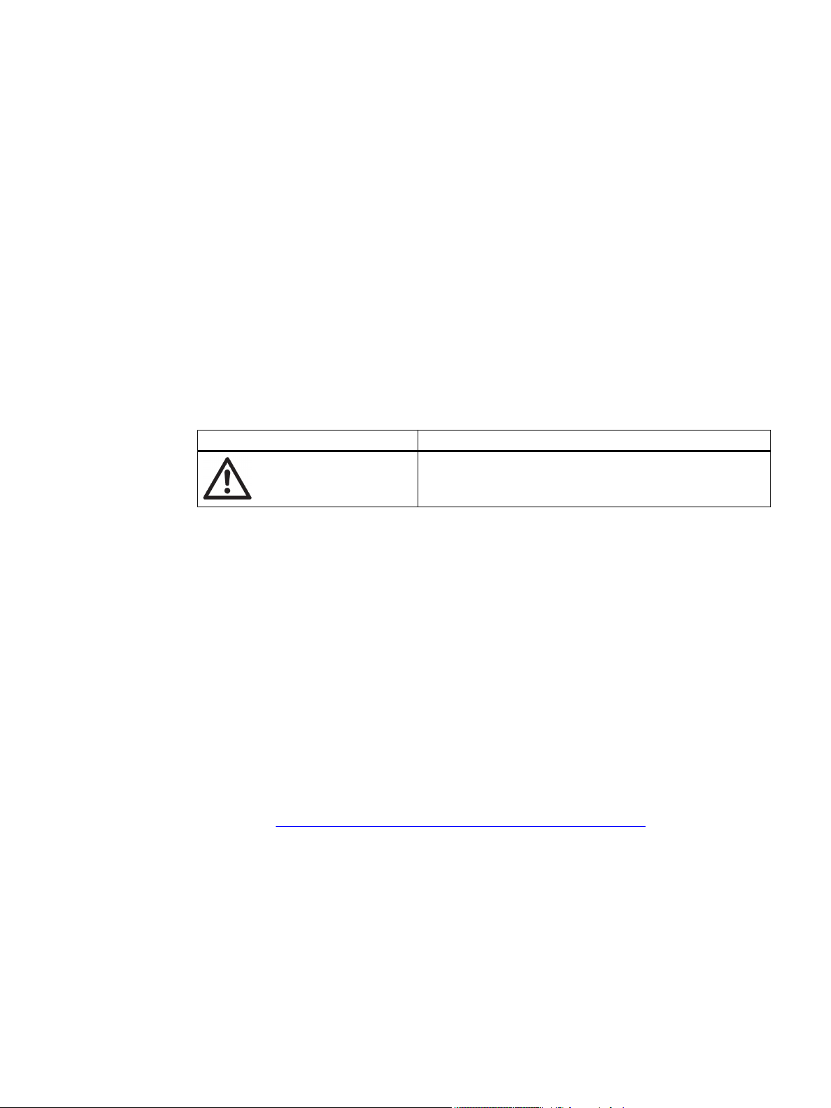
① Pressure gauge block, single-acting
② Valve
③ Yoke / actuator yoke
④ Single-acting positioner in non-flameproof aluminum enclosure
⑤ Actuator
Figure 3-1 Positioner attached to a single-acting linear actuator
① Part-turn actuator
② Pressure gauge block, double-acting
③ Double-acting positioner in polycarbonate enclosure
Figure 3-2 Positioner attached to double-acting part-turn actuator
SIPART PS2 with and without HART
22 Operating Instructions, 05/2017, A5E00074631-AC
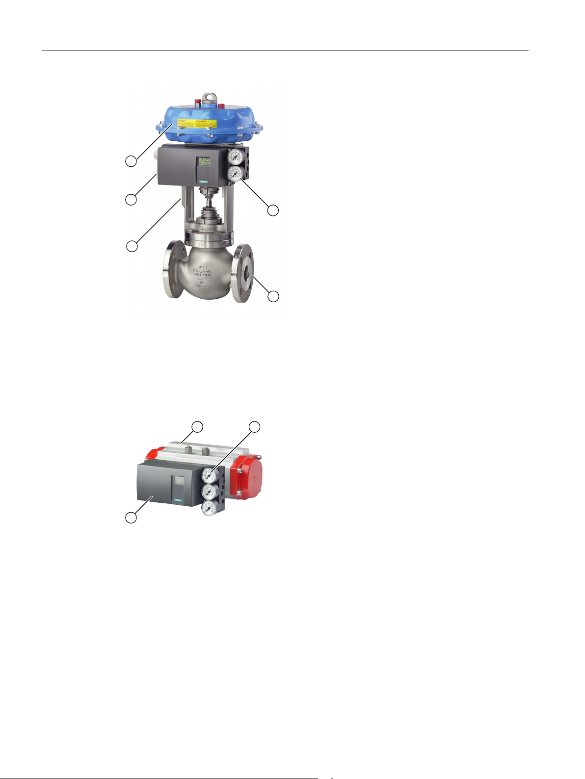
① Single-acting positioner in flameproof aluminum enclosure
② Pressure gauge block, single-acting
③ Yoke / actuator yoke
④ Actuator
Description
3.2 Structure
Figure 3-3 Positioner in flameproof aluminum enclosure attached to linear actuator
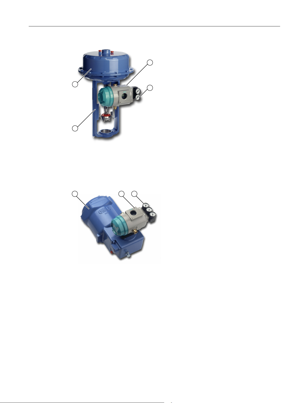
① Part-turn actuator
② Double-acting positioner in flameproof aluminum enclosure
③ Pressure gauge block, double-acting
Figure 3-4 Positioner in flameproof aluminum enclosure attached to part-turn actuator
SIPART PS2 with and without HART
Operating Instructions, 05/2017, A5E00074631-AC 23
-
-
S N°:
-
-
N1A6101234567
13-KB4BO-0369
-
-
-
Technical data and temperature classes see certificate / operating instructions
Ex tD A21 IP66 T100°C
IS / 1 / AEx / Ex ib / IIC IS / I / A-G
-
II 2 G Ex ia IIC T4 Gb II 3 G Ex ic IIC T6/T4 Gc
TÜV 12 ATEX 107540 X / IECEx TUN 12.0028 X
/ TÜV 11.0287 X
Before commissioning permanently
remove indications of the protection
type which are not being used.
Install per control Drawing A5E00065622D
II 2 D Ex ia IIIC 110°C Db II 3 G Ex ec IIC T6/T4 Gc
NI / 1 / 2 / A-D NI / 2 / AEx / Ex ec / IIC
0518
ARR P3-235866.: F-Nr
X.0001 X / TÜV 12.094012 TUN
/X 093266 TEX A 1
TÜV 1
IECEx
Ex tD A21 IP66 T100°C
CL.II, III, DIV.1, GP. EFG
II 2 D Ex tb IIIC T100 °C Db
CL.I, DIV.1, GP. ABCD
II 2 G Ex d IIC T6/T4 Gb
CL.I, ZN.1, AEx d IIC
-40
Ta +50(T6)/80(T4) °C
ZN.21, AEx tb IIIC T100°C Ta=85°C
IP66 / Type 4X
XP, CL.I, DIV.1, GP.CD
Ex d IIC
DIP, CL.II, DIV.1, GP.EFG, CL.III, DIV.1
Technical data and temperature classes see
certificate / operating instructions
SEAL ALL CONDUITS WITHIN 18 INCHES
13-KB4BO-0105
2006.1773456
S-XPL/090873
-40 Ta
+60°C(T6)/80°C(T4)
2001.1233781.
0518
Description
3.2 Structure
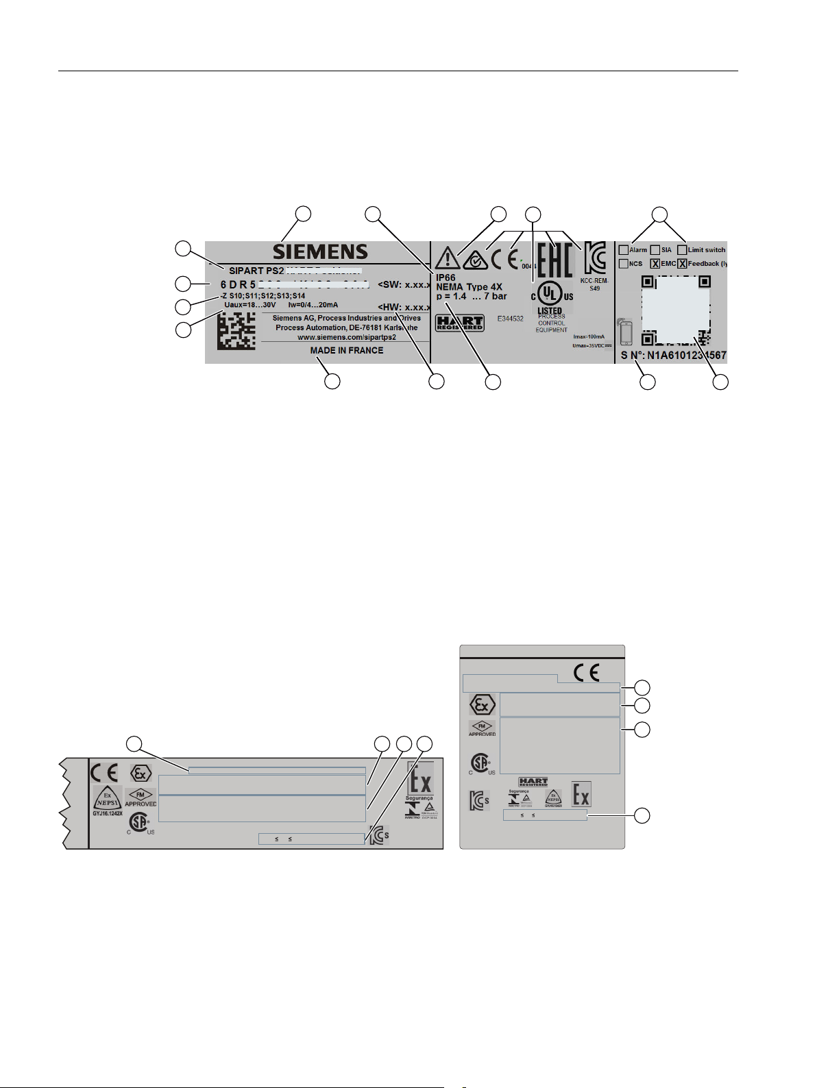
3.2.2 Nameplate layout
Layout of the nameplate
① Manufacturer ⑧ Auxiliary power (supply air PZ)
② Protection class ⑨ Software/hardware version
③ Consult operating instructions ⑩ Place of manufacture
④ Conformity with country-specific directives ⑪ Auxiliary power
⑤ Built-in option module ⑫ Ordering supplement (Order code)
⑥ QR code to the mobile website with device-spe‐
cific information on the product
⑦ Serial number ⑭ Product name
⑬ Article number
Layout of Ex nameplate
① Approvals ③ FM/CSA marking for hazardous area
② ATEX/IECEx marking for hazardous area ④ Permitted ambient temperature for the hazardous
Figure 3-6 Ex nameplate layout, example
24 Operating Instructions, 05/2017, A5E00074631-AC
Figure 3-5 Nameplate layout, example
area of the corresponding temperature class
SIPART PS2 with and without HART

3.2.3 Explanation of Ex information
Technical data and temperature classes see certificate / operating instructions
II 3 G Ex ec IIC T4 Gc
II 2 G Ex ia IIC T4 Gb II 3 G Ex ic IIC T4 Gc
TÜV 12 ATEX 107540 X / IECEx TUN 12.0028 X
/ TÜV 11.0287 X
II 2 D Ex ia IIIC 110°C Db II 2 D Ex tb IIIC T100°C Db
Explanation of Ex information
① Category for operating range ④ Maximum surface temperature (tempera‐
② Type of protection ⑤ Device protection level
③ Group (gas, dust)
Figure 3-7 Explanation of Ex information
Description
3.2 Structure
ture class)
SIPART PS2 with and without HART
Operating Instructions, 05/2017, A5E00074631-AC 25
::
r
r
P$
P$
%,1
r
r
Description
3.3 Device components
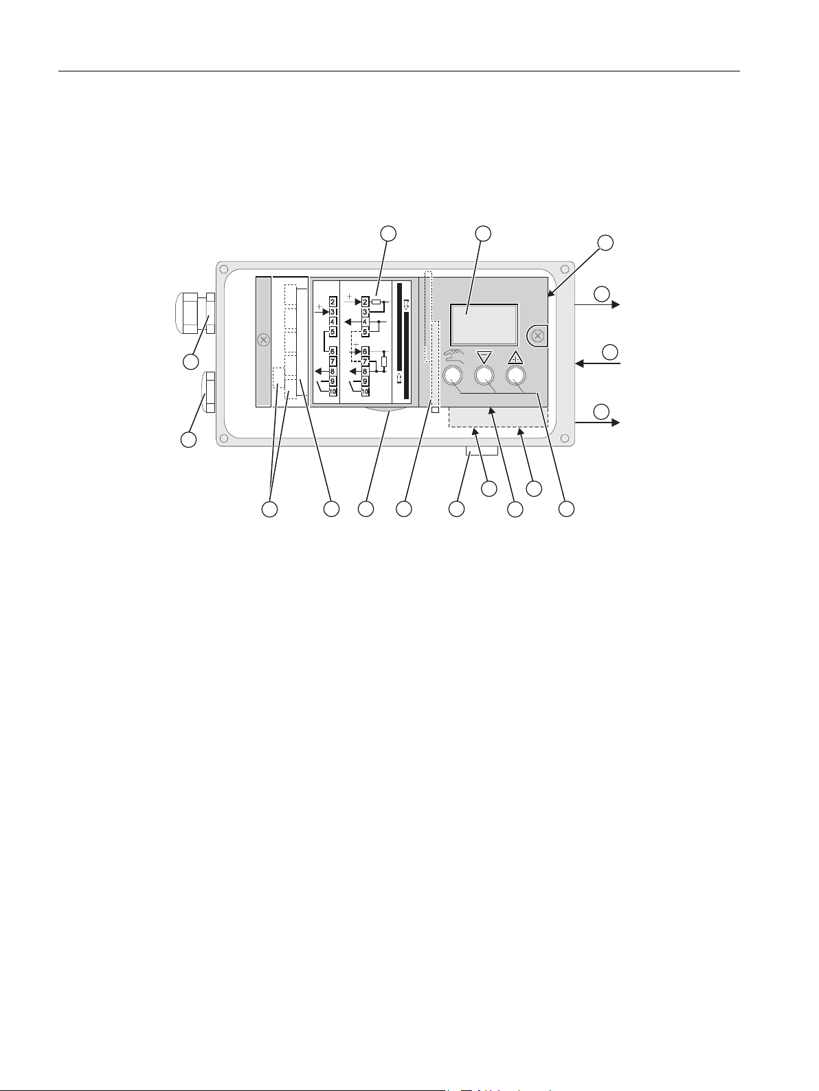
3.3 Device components
3.3.1 Overview of device components
① Input: Supply air PZ ⑩ Transmission ratio selector
2)
② Output: Actuating pressure Y1 ⑪ Friction clutch adjustment wheel
③ Display ⑫ Basic electronics
④ Output: Actuating pressure Y2
1)
⑬ Connecting terminals of option modules
⑤ Buttons ⑭ Dummy plug
⑥ Restrictor Y1 for single-acting actuators ⑮ Cable gland
⑦ Restrictor Y1 for double-acting actuators ⑯ Wiring diagram on module cover
⑧ Restrictor Y2 for double-acting actuators ⑰ Purging air selector
⑨ Exhaust air outlet with a sound absorber
1)
for double-acting actuators
2)
only possible when positioner is open
Figure 3-8 View of positioner with cover open
26 Operating Instructions, 05/2017, A5E00074631-AC
SIPART PS2 with and without HART
$$
-
+
$
$
1
10
138
238
9
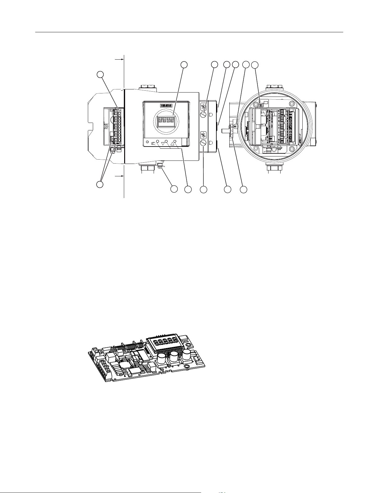
Description
3.3 Device components
① Input: Supply air PZ ⑧ Restrictor Y2
② Output: Actuating pressure Y1 ⑨ Friction clutch adjustment wheel
③ Display ⑩ Connecting terminals of option modules
④ Output: Actuating pressure Y2
⑤ Buttons ⑫ Safety catch
⑥ Transmission ratio selector
⑦ Restrictor Y1
1)
for double-acting actuators
2)
only possible when positioner is open
Figure 3-9 View of positioner in flameproof enclosure, cover opened
3.3.2 Basic electronics
1)
1)
2)
⑪ Connecting terminals of basic electronics
⑬ Ground terminal
Figure 3-10 Basic electronics, schematic representation
The basic electronics contains:
● CPU
● Memory
SIPART PS2 with and without HART
Operating Instructions, 05/2017, A5E00074631-AC 27
● Analog-to-digital converter

Description
3.4 Mode of operation
● Display
● Buttons
● Terminal strips to connect the option module to the basic electronics
3.4 Mode of operation
Control loop
The electropneumatic positioner forms a control loop with the pneumatic actuator:
● The actual value x represents the position of the actuator spindle for linear actuators or the
position of the actuator shaft for part-turn actuators.
● The higher-level control loop provides the setpoint w.
The stroke or rotary movement of the actuator is transferred to a potentiometer using suitable
attachments, positioner shaft and a backlash-free, switchable gear drive, and then to the
analog input of the microcontroller.
Control algorithm
The current position can also be forwarded to the positioner using an external sensor. A NonContacting Position Sensor (NCS) is used to record the stroke or rotary angle directly on the
actuator.
The microcontroller:
● Corrects the angle error of the shaft pick-up if necessary.
● Compares the potentiometer voltage as actual value x with setpoint w.
● Calculates the manipulated variable increments ±∆y.
The piezo-controlled inlet or exhaust air valve is opened depending on the magnitude and
direction of the control deviation (x-w). The actuator volume integrates the controller increment
for the actuating pressure y which is proportional to the drive rod or the drive shaft. This
controller increment change the actuating pressure until the control deviation becomes zero.
Pneumatic actuators are available in single and double-acting versions. In a single-acting
version, only one pressure chamber is ventilated and depressurized. The pressure developed
works against a spring. In a double-acting version, two pressure chambers work against each
other. Ventilating the volume of one chamber simultaneously depressurizes the volume of the
other.
The control algorithm is an adaptive, predictive five-point controller.
In case of large control deviations, the valves are controlled using permanent contact. This
takes place in the so-called fast step zone.
In case of medium control deviations, valves are controlled using pulse-length modulated
pulses. This takes place in the so-called slow step zone.
SIPART PS2 with and without HART
28 Operating Instructions, 05/2017, A5E00074631-AC
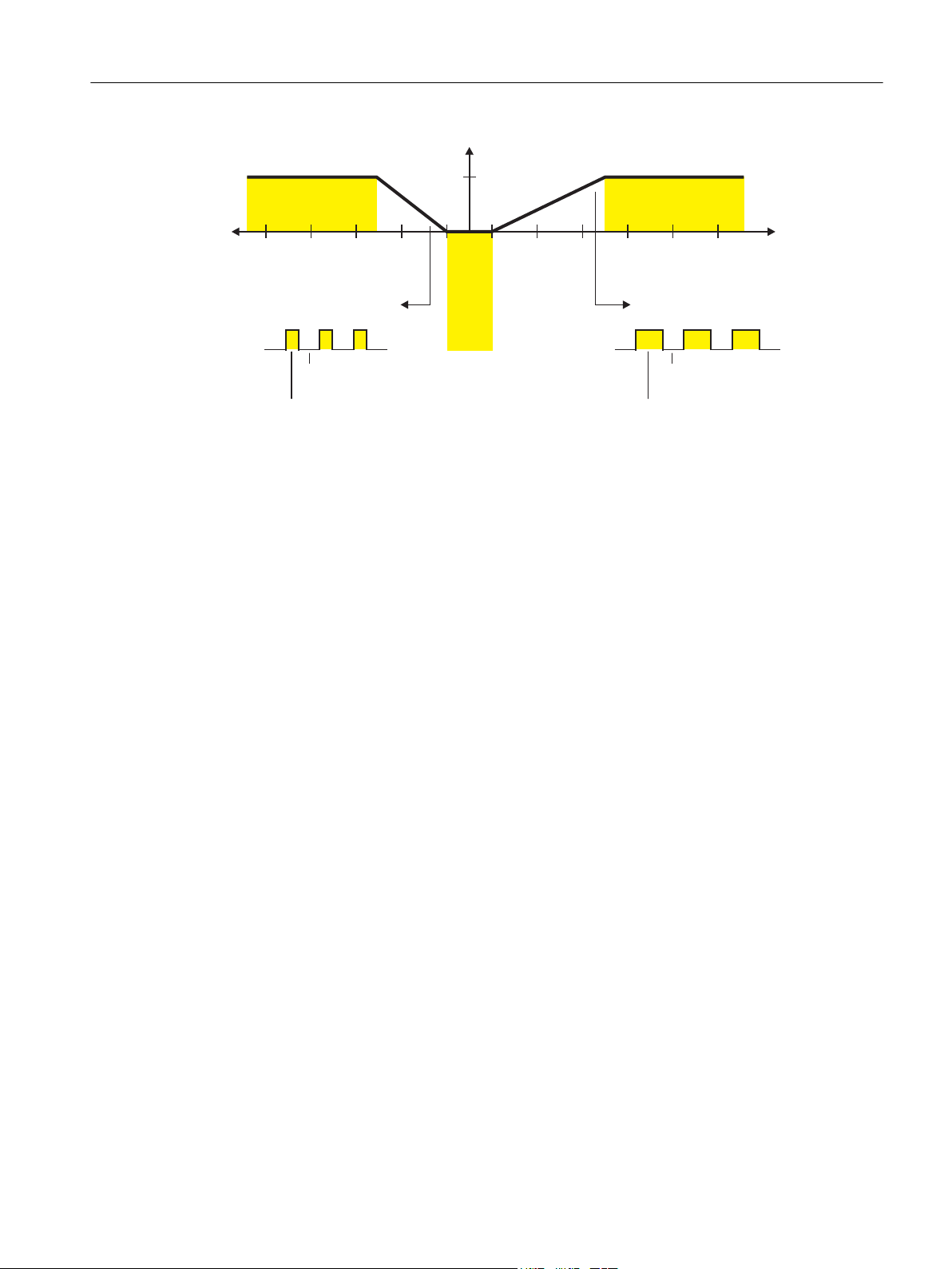
3XOVHOHQJWK
,03'1
3XOVHSDXVH
3$873
3XOVHOHQJWK
,0383
3XOVHSDXVH
3$873
5DQJHRIQHJDWLYHFRQWUROGHYLDWLRQ
)DVWVWHS]RQH
SHUPDQHQWFRQWDFW
)DVWVWHS]RQH
SHUPDQHQWFRQWDFW
[G
9DOYHRSHQV
[G
9DOYHFORVHV
6ORZVWHS]RQH
YDULDEOHSXOVHGXW\IDFWRU
'HDGEDQG
3XOVHGXW\
IDFWRU
WR
5DQJHRISRVLWLYHFRQWUROGHYLDWLRQ
6ORZVWHS]RQH
YDULDEOHSXOVHGXW\IDFWRU
Description
3.4 Mode of operation
Figure 3-11 Functional principle of five-point controller
Small control deviations do not send control pulses in the zone. This takes place in the socalled adaptive deadband. The deadband adaptation and the continuous adaptation of
minimum pulse lengths in "Automatic" mode ensure the best possible control accuracy with
the smallest number of operating cycles. The start parameters are determined during the
initialization phase and stored in the non-volatile memory. The most important start parameters
are:
● The real actuator travel with end positions
● Travel times
● The deadband size
The number of fault messages, changes in direction, and the number of total strokes are
continuously determined during operation and saved every 15 minutes. You can read and
document these parameters using communication programs such as SIMATIC PDM and AMS.
By comparing the old values with the current ones, you can draw conclusions about the wear
and tear of the valve. You can use the diagnostics function for this.
SIPART PS2 with and without HART
Operating Instructions, 05/2017, A5E00074631-AC 29
6XSSO\
([KDXVW
([KDXVW
0LFUR
FRQWUROOHU
+$57
9
9
+XE
+XE
:
:
$
'
$
'
S
S
S
%,1
,
:
,
:
\
[
[
8
\
\
%,1$$
$$
8
8
,
<
<
<
<
S
=
Description
3.4 Mode of operation
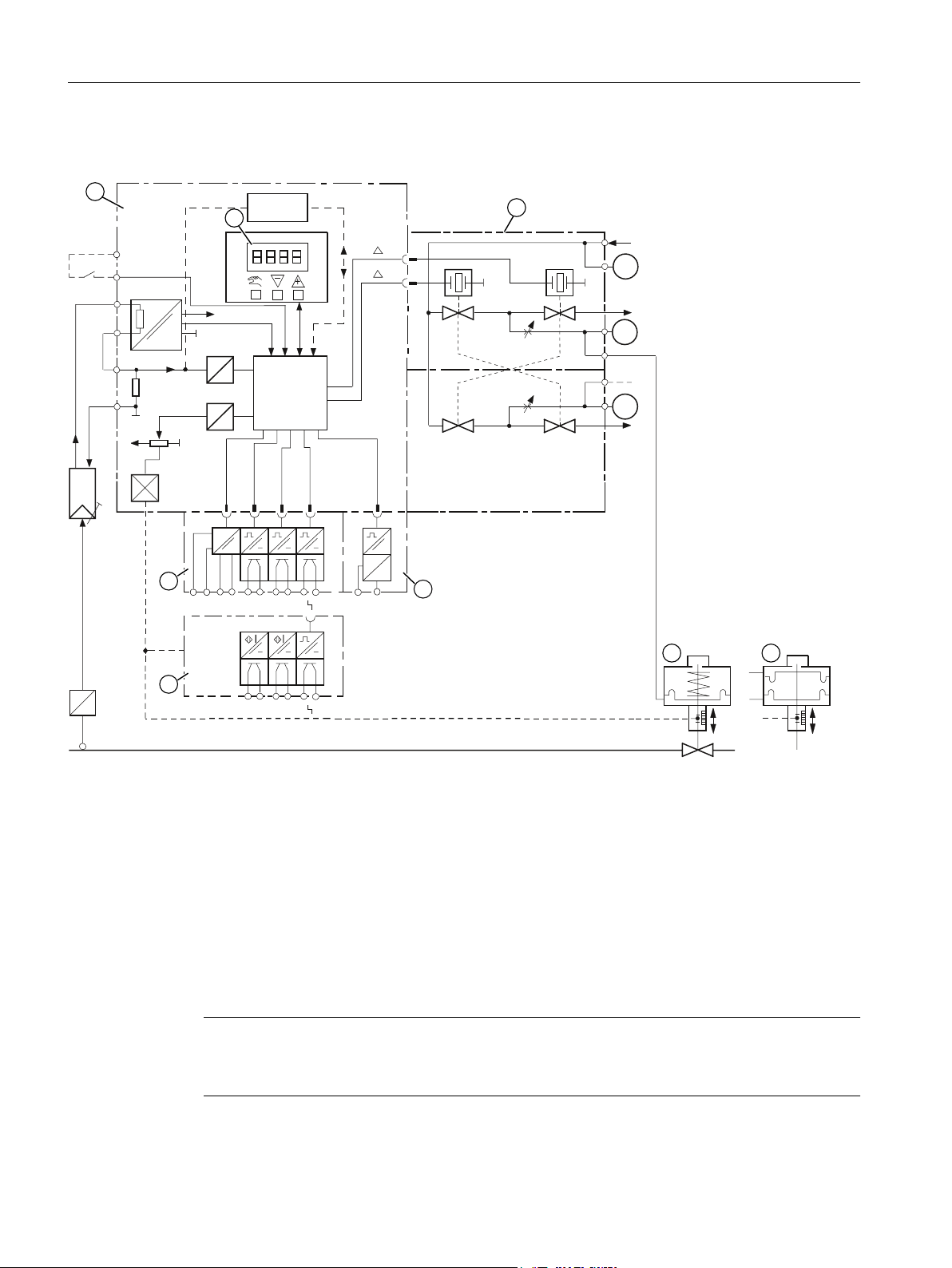
3.4.1 Block circuit diagram for single-acting or double-acting actuators
① Basic electronics with microcontroller and input circuit
② Control pad with display and buttons
③ Single-acting or double-acting pneumatic block
④ Position feedback module for positioner
⑤ Alarm module for three alarm outputs and one binary input
⑥ SIA module (slot initiator alarm module)
⑦ Spring-loaded pneumatic actuator (single-acting)
⑧ Pneumatic actuator (double-acting)
Figure 3-12 Block circuit diagram for the electropneumatic positioner, functional diagram
Note
Alarm module and SIA module
Alarm module ⑤ and SIA module ⑥ can only be alternatively used.
30 Operating Instructions, 05/2017, A5E00074631-AC
SIPART PS2 with and without HART
 Loading...