

Siemens SIPART DR24, 6DR2410 User Manual
Manual Edition 12/2006
Controller
SIPART DR24
6DR2410
sipart


SIPART DR24
6DR2410
Edition 12/2006
Manual
SIPART DR24 6DR2410
C79000-G7476-C153-03
1
Block diagram
Manual
AE1
AE2
AE3
AE4
AE5
BE1
2
3
BE4
L+
M
+
-
+
-
+
-
Options
M
2
Front
module
1/20
1/19
1/22
1/21
1/24
1/23
2/4
2/3
2/2
2/1
3/4
3/3
3/2
3/1
1/15
1/16
1/17
1/18
1/3
1/2
1/1
PE
I,U
U
I,U
U
I,U
U
I,U,R
UNI,
P,
T,
V
U
Slot 2
I,U,R
UNI,
P,
T,
V
U
Slot 3
24 V
5V
S3
L
N
«
6DR2410-4 24 V UC
6DR2410-5 115/230 V AC switchable
32 Basic functions 109 arithmetic blocks
AbS, Add, AMEM,
AMPL, And,
ASo
bSo
CoMP, CoUn
dEbA, dEF, diF
tA1.1
div
#
Eor
tA7.F
FiLt b01.F...bh9.F
LG, LiMi, LinE with 3 inputs
Ln 1 output
AE1A
MAME, MASE
MiME, MiSE
MULt
nAnd, nor
AE2A
or
Pot
root
SUb
AE3A
tFF, tiME
33 complex funct. 33 arithmetic blocks
AFi1. AFi2
Ain1...Ain4
bin1...bin6 c01.F...c33.F
CPt1, CPt2 with 4 inputs
AE4A
dti1, dti2 1 output
FUL1, FUL2, FUL3
FUP1, FUP2
PUM1 - 4/SPR1 - SPR8
4 complex funct. 4 arithmetic blocks
CLoc d01.F...d04.F
MUP1, M UP2 with 12 inputs
AE5A
Cnt1 14 outputs
12 complex funct. 4 arithmetic blocks
Ccn1...Ccn4 h01. F...h04. F
CSE1...CSE4 with 18 inputs
CSi1...CSi4 4 outputs
bE01
bE02
bE03
bE04
I
M
+24V
+5V
U
–
REF
User
program
memory for:
onPA onAdAP line
oFPA
CLPA
hdEF offFdEF line
FCon
FPoS
APSt
CAE4
CAE5
dA1.1...dA2.4
dd1.1...dd3.4
L 1.1...L14.9
AA1.1...AA1.3
AA2.1...AA2.3
AA3.1...AA3.3
bA1.1...bA1.3
bA2.1...bA2.3
bA3.1...bA3.3
bA4.1...bA4.3
bA05
bA06
bA07
bA08
AE6A...AE8A
AA4...AA6
bE10...bE14
bA13...bA16
AE9A...AE11A
AA7...AA9
bE05...bE09
bA09...bA12
SA1.1...SA16.3
SAA1...SAA16
SbE1...SbE16
SbA1...SbA16
F
r
o
n
t
m
0000
o
d
u
l
e
5V
24 V I
3AE
1AA y
5BE
4BA24V
+2BE
2BA Rel.
3AO/3BE
Slot 6
3AE
1AA y
5BE
4BA 24V
+2BE
2BA Rel.
3AO/3BE
Slot 5
RS 232/
RS 485
PROFIBUS
Slot 4
U
U
U
hold
hold
Slot Term i n al
1/12
I
1/13
I
1/14
I
1/10
1/11
4/2
4/7
4/8
4/3
SIPART DR24 6DR2410
C79000-G7476-C153-03
1/4
1/5
1/6
1/7
1/8
1/9
6/6
6/5
6/4
6/3
6/2
6/1
Options
5/6
5/5
5/4
5/3
5/2
5/1
Options
AA1
AA2
AA3
BA1
2
3
4
5
6
7
BA8
Manual
dA1
tA7
*) or dA2
dd1
dd2
green
red
yellow
gray
L14.0
L14.1
L14.2
L14.3
L14.4*)
L14.5
L14.6
L14.7
L14.8
L14.9
L13
dd3 L12
Measuring point label with cover, changeable
Process operation Parameterization/configuring
L1 LED green -tA1 Key green Exit key
L2 LED green Exit LED
L3 LED yellow -L4 LED red -L5 LED red -tA2/3 Key green Adjustment of the variables shown in
L6 LED red -L7 LED red -L8 LED yellow -tA4 Key yellow Enter key
L9 LED yellow Enter LED
L10 LED green -tA5 Key gray Shift key; start of configuration
L11 LED green -L12 LED yellow -tA6/7 Adjustment of the variables show in the
L13 LED yellow -L14.0 bis L14.9 Striped pattern in configuring
LEDs green (only as
an alternative to digital
display dA2)
dd1 Digital display green Parameter value/answer
dd2 Digital display red Function, parameter name, question
dd3 Didital display yellow Parameter name
dA1 Analog display red - dA2 Analog display green Striped pattern in configuring
(only as an alternative
to L14)
L1
L2
L3
L4
L5
L6
L7
L8
L9
L10
L11
tA1
tA2
tA3
tA4
tA5
tA6
the digital display dd1
digital displays dd2 and dd3
Figure 3-1 Connectable control and display elements in the process operation mode and fixed
assignment in parameterization/configuring
SIPART DR24 6DR2410
C79000-G7476-C153-03
3

Manual
Classification o f safety--related notices
This manual contains notices which you shouldobserve toensure your own personalsafety, as well
as to protect the product and connected equipment. These notices are highlighted in the manual
by a warning triangle and are marked as follows according to the level of danger:
DANGER
!
!
!
indicates an immenently hazardous situation which, if not avoided, will result in death or serious inury.
WARNING
indicates a potentially hazardous situation which, if not avoided, could result in death or serious injury.
CAUTION
used with the safety alert symbol indicates a potentially hazardous situation which, if not avoided, may
result in minor or moderate injury.
CAUTION
used without the safety alert symbol indicates a potentially hazardous situation which, if not avoided, may
result in property damage.
NOTICE
indicates a potential situation which, if not avoided, may result in an undesirable result or state.
.
Copyright e Siemens AG 2006 All rights reserved
The reproduction, transmission or use of this document or
its contents is not permitted without express written authority. Offenders will be liable for damages. All rights, including rights created by patent grant or registration of a utility
model or design, are reserved.
Siemens AG
Automation and Drives
Postfach 48 48
90437 NÜRNBERG
DEUTSCHLAND
NOTE
highlights important information on the product, using the product, or part of the documentation that is of
particular importance and that will be of benefit to the user.
Trademarks
Disclaimer of Liability
We have checked the contents of this manual for agreement with the hardware and software described. Since
deviations cannot be precluded entirely, we cannot guarantee full agreement. However, the data in this manual are
reviewed regularly and any necessary corrections included
in subsequent editions. Suggestions for improvement are
welcomed.
e Siemens AG 2006
Technical data subject to change.
SIMATICR,SIPARTR,SIRECR, SITRANSR registered trademarks of Siemens AG.
Third parties using for their own purposes any other names in this document which refer to trademarks might infringe upon the
rights of the trademark owners.
4
SIPART DR24 6DR2410
C79000-G7476-C153-03

Manual Contents
Contents
Page
1 Technical Description 7........................................................
1.1 Safety Notes and Scope of Delivery 7......................................................
1.2 Range of Application 8...................................................................
1.3 Design (Hardware) Software 8............................................................
1.4 Function Principle 11....................................................................
1.4.1 Standard Controller 11.......................................................................
1.4.2 Description of the Option Module 12...........................................................
1.4.3 Self-diagnostics of the CPU 19................................................................
1.4.4 Data Storage, User Program Memory 20.......................................................
1.5 Functional Description 21................................................................
1.5.1 Basic Structure 21..........................................................................
1.5.2 Input Functions 24..........................................................................
1.5.3 Output Functions 29.........................................................................
1.5.4 Serial Interface (SES) and PROFIBUS DP (Input/Output Functions) 34..............................
1.5.5 Data Sources with Message Function (Digital Outputs #) 36.......................................
1.5.6 Error Messages 38..........................................................................
1.5.7 Basic Functions (Arithmetic blocks b) 42........................................................
1.5.7.1 General 42.............................................................................
1.5.7.2 Mathematical Functions 44...............................................................
1.5.7.3 Logical Functions 46.....................................................................
1.5.7.4 Timing Functions 49.....................................................................
1.5.7.5 Comparison and Switching Functions 50....................................................
1.5.8 Complex Functions (Arithmetic blocks c, d, h) 52.................................................
1.5.8.1 General 52.............................................................................
1.5.8.2 Arithmetic Blocks c01.F to c33.F 53........................................................
1.5.8.3 Arithmetic Blocks d01.F to d04.F 66........................................................
1.5.8.4 Arithmetic Blocks h01.F to h04.F 75........................................................
1.5.9 Restart Conditions 91.......................................................................
1.5.10 Arithmetic 91...............................................................................
1.6 Technical Data 93.......................................................................
1.6.1 General Data 93............................................................................
1.6.2 Standard Controller 95.......................................................................
1.6.3 Technical Data of the Options Modules 99......................................................
2 Installation 107................................................................
2.1 Mechanical Installation 107..............................................................
2.2 Electrical Connection 107...............................................................
2.2.1 Block Diagram 111..........................................................................
2.2.2 Wiring of the standard Controller 112...........................................................
2.2.3 Wiring of the Option Modules 115..............................................................
2.2.4 Alternative Wiring for I- and U Input 123........................................................
2.2.5 Wiring of the Interface 128...................................................................
3 Operation 131.................................................................
3.1 Process Operation Mode 131............................................................
3.2 Selection Mode 131....................................................................
3.3 Configuring Mode (Parameterization and Configuring Mode) 135..............................
3.3.1 Parameterization Mode onPA (Online Parameters) 136...........................................
3.3.2 Parameterization Mode AdAP (Adaptation) 138..................................................
3.3.3 Configuring Mode oFPA (Offline Parameters) 145................................................
3.3.4 Configuring Mode CLPA (Clock Parameters) 148................................................
3.3.5 Configuring Mode hdEF (Define Hardware) 150..................................................
3.3.6 Configuring Mode FdEF (Define Functions) 152..................................................
3.3.7 Configuring Mode FCon (Switch Functions, Connection) 155.......................................
3.3.8 Configuring Mode FPoS (Position Functions) 159................................................
3.3.9 Configuring Mode APSt (All Preset, Factory Setting) 162..........................................
SIPART DR24 6DR2410
C79000-G7476-C153-03
5

Contents
3.3.10 Configuring Mode CAE4/CAE5 -- Setting UNI Module(s) 163.......................................
3.3.10.1 Measuring Range for mV (SEnS=Mv.) 164...................................................
3.3.10.2 Measuring Range for U, I (SEnS=Mv.) 164..................................................
3.3.10.3 Measuring Range for Thermocouple with Internal Reference Point (SEnS=tc.in) 165................
3.3.10.4 Measuring Range for Thermocouple with External Reference Point (SEnS=tc.EH) 165..............
3.3.10.5 Measuring Range for PT100--4--wire and PT100--3--wire Connection (SEnS=Pt.3L/PT.4L) 165.......
3.3.10.6 Measuring Range for PT100--2--wire Connection (SEnS=Pt.2L) 166.............................
3.3.10.7 Measuring Range for Resistance Transmitter (SEnS=r._ for R < 600 Ω, SEnS=r. for R< 2.8 kΩ) 166..
Manual
4 Commissioning 167...........................................................
4.1 General Information 167.................................................................
4.2 Test 167..............................................................................
5 Maintenance 169..............................................................
5.1 General Information and Handling 169....................................................
5.2 Spare Parts List 173....................................................................
6 Ordering Data 175.............................................................
7 User Examples 177............................................................
7.1 Maximum Selection (Example 1) 177......................................................
7.2 Mathematical Link (Example 2) 180.......................................................
7.3 Set Value Controller K (Example 3) 184....................................................
7.4 Two-position Controller for Heating and Cooling (Example 4) 188..............................
7.5 Switching Over the Display Levels (Process Operation Mode) (Example 5) 191.................
8 Programming Aids 195........................................................
9 List of Abbreviations 261......................................................
Index 267..........................................................................
6
SIPART DR24 6DR2410
C79000-G7476-C153-03

Manual
1 Technical Description
1.1 Safety Notes and Scope of Delivery
1.1 Safety Notes and Scope of Delivery
1 Technical Description
!
WARNING
When operating electrical equipment, certain parts of this equipment
automatically carry dangerous voltages. Failure to observe these
instructions could therefore lead to serious injury or material damage.
Only properly trained and qualified personnel are allowed to work on this
equipment. This personnel must be fully conservant with all the
warnings and commissioning measures as described in this Manual.
The perfect and safe operation of this equipment is conditional upon
proper transport, proper storage, installation and assembly as well as on
careful operation and commissioning.
D Scope of delivery
When the controller is delivered the box also contains:
1 Controller as ordered
1 three--pin plug at 115/230 V AC or special plug at 24 V UC
2 Clamps, pluggable
1 Assembly and installation instructions German/English, order number
C79000-M7474-C38
D Basic equipment
The following variants of the SIPART DR24 are available:
Order number Power supply
6DR2410-4
6DR2410-5
24 V UC
115/230 V AC, switchable
D Option module
Signal converters have separate ordering and delivery items. For handling reasons basic
equipment and signal converters which were ordered at the same time may be delivered by
separate mail.
D Documentation
This user’s guide is available in the following languages:
English C79000-G7476-C153
German C79000-G7400-C153
SIPART DR24 6DR2410
C79000-G7476-C153-03
7

1 T echnical Description
1.2 Range of Application
Manual
D Subject to change
The manual has been compiled with great care. However, it may be necessary within the
scope of product care to make changes to the product and its operation without prior notice
which are not contained in this manual. We are not liable for any costs ensuing for this reason.
1.2 Range of Application
The SIPART DR24 is a digitally operating device in the top class range. Its program memory
contains a large number of prepared function blocks for calculating, controlling, regulating in
chemical engineering processes which the user can implement without programming knowledge
and additional tools. Mathematical functions, logical functions, comparison and switching functions, timing functions, memory functions, control functions and a program generator are stored.
All function blocks are freely connectable with each other and with different inputs and outputs
of the controller by the software.
The controller can therefore be used to solve a wide range of different problems. A large number of display elements (digital, analog displays, LEDs) and control elements allow display and
control of the processes on the front panel.
This controller contains a rugged adaptation procedure for the stored controller components
which noticeably simplifies commissioning of even critical control loops. The controller determines the optimized control parameters independently on request without the user being expected to have any prior knowledge of how the control loop may respond.
The SIPART DR24 can operate with up to 4 independent control loops. Tasks in which it is necessary to use interconnected control equipment (e.g. cascaded control, cascaded ratio controls
or override controls) can therefore be performed with one controller .
The extensive hardware equipment of the controller allows its universal application and provides
a large number of interfaces to the control loop.
The controller can be connected to master systems through a pluggable serial interface
(RS 232/RS 485 or PROFIBUS DP) or operated and monitored centrally by a Personal
Computer.
1.3 Design (Hardware) Software
The SIPART DR24 has a modular design and is therefore service friendly and easy to convert
and retrofit. Other signal converters can be installed in the generously equipped, fully functional
standard controller to expand the range of application. These modules are installed in slots at
the back of the closed device (Figure 1--2, page 10).
The standard controller consists of
-- the front module with the control and display elements
-- the main board with CPU and terminal strips
-- the plastic housing with an interface board
-- the power supply unit.
8
SIPART DR24 6DR2410
C79000-G7476-C153-03

Manual
1.3 Design (Hardware) Software
1 Technical Description
The electrical connections between the modules are made by an interface board screwed into
the housing. The main board is pushed into rear slot 1 and locked. It holds a 10--pin and a
14--pin terminal strip to which all inputs and outputs of the standard controller are connected.
Five other slots can be equipped with option modules if the number of terminals to the process
available in the standard controller are not sufficient for the planned task.
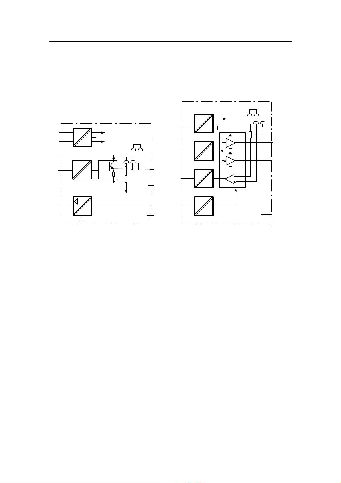
The basic device always has three permanently installed analog inputs (AE) with electronic potential isolation which can be wired alternatively with standardized voltage signals (0/0.2 to 1 V
or 0/2 to 10 V) or current signals (0/4 to 20 mA). There are also four digital inputs (BE, 0/24 V)
and eight digital outputs (BA, 0/24 V, 50 mA) which can be used for different functions depending on the configuration.
The SIPART DR24 also has three analog outputs which can all supply a current signal from 0 to
20 mA or 4 to 20 mA and be assigned to different variables.
A short--circuit--proof L+--output (DC 24 V , 100 mA) is available for supplying transmitters.
The power supply unit is located in a fully enclosed metal casing and is screwed tightly to the
plastic housing of the controller.
Many applications can be implemented with the three permanently available analog inputs of
the standard controller alone. Two additional input modules can be inserted in slots 2 and 3 for
complex jobs or for the connection of other input signals. These input modules are available in
addition to for processing normalized current and voltage signals for the direct connection of
resistance thermometers Pt100 and all common thermocouples and resistance sensors or potentiometers. In addition a module with three analog inputs (equipment as in the standard controller) can be inserted in slots 5 and 6. This increases the number of inputs to a total of 11.
Slot 4 serves to accommodate an interface module (SES) with V.28 point-to-point output or
SIPART bus interface for serial communication with a master system. A PROFIBUS interface
module can be equipped optionally here.
The slots 5 and 6 can accommodate signal converters of different functions and can be
equipped optionally with modules for expanding digital inputs or digital outputs.
Following assemblies are possible:
2 relays
4 digital outputs/2 digital inputs
5 digital inputs
3 analog outputs/3 digital inputs
1 analog output with digital fault output (y
function) with remote supply
hold
3 analog inputs
SIPART DR24 6DR2410
C79000-G7476-C153-03
9
1 T echnical Description
1.3 Design (Hardware) Software
Manual
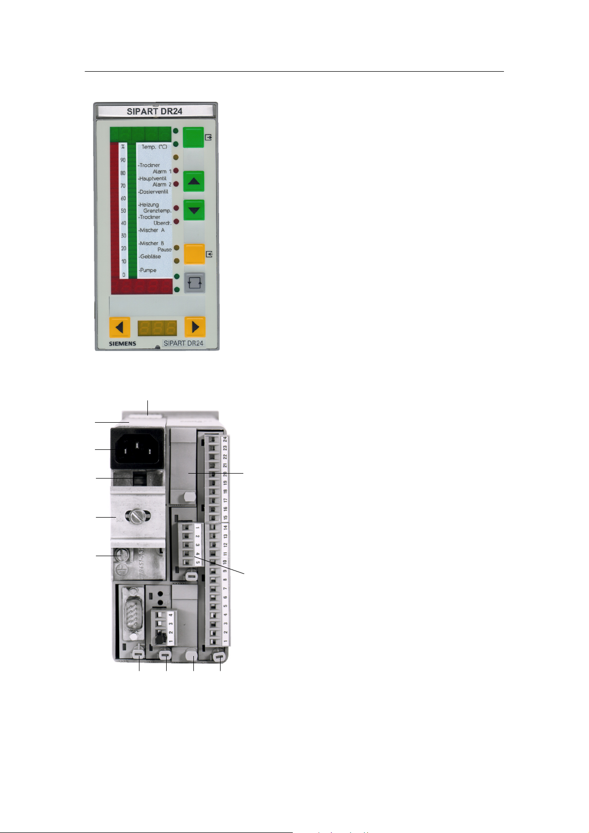
Figure 1--1 Front view of the SIPART DR24
1
12
11
10
9
8
2
3
Legend:
2. PE conductor contact spring
3. Slot 6
4. Slot 5
5. Slot 1 (main board)
6. Slot 2
7. Slot 3
8. Slot 4 (SES: RS 232/
RS 485, Profibus DP)
9. Grounding screw
10. DIN rail (DIN rail delivered with
interface relays)
11. Selection switch Mains voltage
12. Mains plug
13. Power supply unit
7 6 5 4
Figure 1--2 Rear view of the SIPART DR24
10
SIPART DR24 6DR2410
C79000-G7476-C153-03

Manual
1 Technical Description
1.4 Function Principle
1.4.1 Standard Controller
1.4 Function Principle
1.4.1 Standard Controller
The standard controller consists of three function blocks:
-- Power supply unit
-- Front module
-- Main board
Power supply unit
Primary clocked power supply unit with high efficiency for AC 115/230 V (switchable) or for
UC 24 V. It generates the secondary internal supply voltages +24 V and +5 V from the power
supply. The metal body is mounted on PE conductors (protection class I). The power supply
and internal supply voltages are isolated from each other by safe separation by a protective
shield. The internal supply voltages are functional extra--low voltages due to overvoltage cutoff
in the event of an error. Since no further voltages are generated in the controller, these statements apply for all field signal lines (used standards, see chapter 1.6, page 93). A total of
450 mA are available for the outputs L+, AA and BA due to the design for a high power output.
Front module
The front module contains the control and display elements and the appropriate trigger components for the displays.
All display elements are designed in LED technology which provides a longer service life and
higher light density as well as a good viewing angle. The control elements are short--stroke
switches with a tangible ”pressure” and high return force. They are actuated by flexible actuators through the cover foil which are designed so that the foil is not subjected to any excess
stress.
The SIPART DR24 has a great number of functional variants. The configured buttons and display elements are activated depending on the function in the front module.
There is a foil behind the front foil which can be labeled to suit requirements. In this way the
display and control elements can be assigned to the functions.
Main board
The main board contains the field signal conditioning of the standard controller, the CPU
(Central Processing Unit) and the connections (through the interface board) to the module slots.
The field signals are fed through protective circuits for external static or dynamic overvoltages
and then adapted to the signal levels of the CPU by the appropriate circuits. This adaptation is
performed for the analog inputs, the analog outputs and the digital outputs by modern thick--film
circuits.
The microcontroller used has integrated AD- and DA converters and operates with 32k battery-backed RAM. The user--specific configuration is stored in an exchangeable user program
memory with a serial 4k EEPROM. This makes it possible to plug the user program memory in
the new controller to be installed when servicing. This then does not need to be re--configured.
SIPART DR24 6DR2410
C79000-G7476-C153-03
11

1 T echnical Description
1.4 Function Principle
1.4.2 Description of the Option Module
Manual
The whole CPU is designed in C--MOS technology. The program of the SIPART DR24 operates
with a variable cycle time which depends on the scope of the program (see chapter 1.5.1,
page 21).
A process image is generated at the start of every routine. The analog and digital inputs and
actuation of the front buttons is included and the process variables received from the serial interface are accepted. All calculations are performed with these input signals according to the
stored functions. Then the data are output to the display elements, the analog outputs and the
digital outputs as well as storage of the calculated variables on standby for the serial interface
transmitter. The interface traffic runs in interrupt mode.
A large number of arithmetic and function blocks is stored in the set value memory of the
SIPART DR24. The user programs the controller himself by selecting, connecting and timing the
desired functions by configuration. The entire function of the controller results from the combination of the individual function blocks (basic functions, complex functions) and the corresponding input and output circuits. Programming knowledge is not necessary for the settings.
All settings are made without an additional programming device at the operating panel of the
SIPART DR24 or via the serial interface. The job--specific program written in this way is saved
in the non--volatile user program memory.
There are 32 basic function blocks b**.F and a total of 59 complex functions c**.F, d0*.F, h0*.F
which can be used with varying frequency.
No function is stored when the controllers are delivered (factory setting, all preset) The displays
are not connected. (Flashing message APSt MEM appears after switching on.)
1.4.2 Description of the Option Module
The following option modules are described in this chapter
6DR2800--8A 3 AE module
6DR2800-8J I/U module
6DR2800-8R R module
6DR2800-8V UNI module
6DR2805-8A Reference point
6DR2805-8J Measuring range plug
6DR2801-8D Module with 2 BA (relays)
6DR2801-8E Module 2 BE and 4 BA
6DR2801-8C Module with 5 BE
6DR2802-8A Analog output module with y-hold function
6DR2802-8B Module with 3AA and 3BE
6DR2803-8P Serial interface PROFIBUS-DP
6DR2803-8C Serial interface RS 232/RS 485
6DR2804-8A 4 BA relays
6DR2804-8B 2 BA relays
12
SIPART DR24 6DR2410
C79000-G7476-C153-03

Manual
1.4.2 Description of the Option Module
1 Technical Description
1.4 Function Principle
6DR2800-8A 3 AE module
D Inputs for current and voltage
To expand the analog inputs.
Description of the module and technical data, see chapter 1.6.2, page 95 (Inputs standard controller).
6DR2800-8J I/U module
D Input variables current 0/4 to 20 mA or voltage 0/0.2 to 1 V or 0/2 to 10 V
The input amplifier of the module is designed as a differentiating amplifier with jumperable gain
for 0 to 1 V or 0 to 10 V input signal. For current input signals the 49.9 W 0.1 % impedance is
switched on by plug--in bridges on the module. The start value 0 mA and 4 mA or 0 V or 0.2 V
(2 V) is defined by configuration in the standard controller. The differentiating amplifier is designed for common mode voltages up to 10 V and has a high common mode suppression.
As a result it is possible to connect the current inputs in series as for electrical isolation when
they have common ground. At voltage inputs this circuit technique makes it possible to suppress the voltage dips on the ground rail by two--pole wiring on non floating voltage supplies.
We refer to an electronic potential isolation.
6DR2800-8R R module
D Input for resistance or current transmitter
Potentiometers with rated values of 80 Ω to 1200 Ω can be connected as resistance
transmitters. A constant current of Is = 5 mA is fed to the potentiometer wiper. The wiper
resistance is therefore not included in the measurement. Resistances are switched parallel to
the potentiometer by a slide switch on the module and a rough range selection made. Range
start and end are set with the two adjusting pots on the back of the module.
This fine adjustment can be made via the displays on the front module (with the appropriate
configuring). For adjustment with a remote measuring device, the analog output can be assigned to the appropriate input.
The external wiring must be changed for resistance transmitters which cannot withstand the
5 mA wiper current or which have a rated resistance > 1 kΩ. The constant current is then not
fed through the wiper but through the whole resistance network of the potentiometer. A voltage
divider measurement is now made through the wiper. Coarse adjustment is made by a remote
parallel resistor to the resistance transmitter.
This module can also be used as a current input with adjustable range start and end. The load
is 49.9 Ω and is referred to ground.
SIPART DR24 6DR2410
C79000-G7476-C153-03
13

1 T echnical Description
1.4 Function Principle
1.4.2 Description of the Option Module
Manual
6DR2800-8V UNI module
D Direct connection of thermocouple or Pt100 sensors, resistance or mV transmitters
Measured value sensors such as thermocouples (TC), resistance thermometers Pt100 (RTD),
resistance transmitters (R) or voltage transmitters in the mV range can be connected directly.
The measuring variable is selected by configuring the controller in the HdeF level (AE4/AE5);
the range and the other parameters are set in the CAE4/CAE5 menu. The sensor--specific characteristics (linearization) for thermocouples and Pt100 resistance thermometers are stored in
the contoller’s program memory and are automatically taken into account. No settings need to
be made on the module itself.
The signal lines are connected via a plug terminal block with screw terminals. When using thermocouples with internal reference point, this terminal block must be replaced by the terminal
6DR2805-8A. With the measuring range plug 6DR2805--8J in place of the terminal block, the
range of the direct input (0/20...100 mV) can be extended to 0/2...10 V or 0/4...20 mA.
The UNI module operates with an AD converter with 18 bit resolution. The measuring inputs
and ground of the standard controller are electrically isolated with a permissible common mode
voltage of 50 V UC.
6DR2805-8A Reference point
D Terminal with internal reference point for thermocouples
This terminal is used in connection with the UNI module for temperature measuring with thermocouples at an internal reference point. It consists of a temperature sensor which is pre--assembled on a terminal block and plated to avoid mechanical damage.
6DR2805-8J Measuring range plug
D Measuringrangeplugforcurrent0/4to20mAorvoltage0/2to10V
The measuring range plug is used in connection with the UNI module to measure current or
voltage. The input variable is reduced to 0/20 to 100 mV by a voltage divider or shunt resistors
in the measuring range plug.
Loop resistances with 250 Ω or 50 Ω are available optionally at 2 different terminals for 0/4 to
20 mA signals.
The electrical isolation of the UNI module is retained even when the measuring range plug is
used.
6DR2801-8D 2 BA relays
D Digital output module with 2 relay contacts
To convert 2 digital outputs to relay contacts up to 35 V UC.
This module is equipped with 2 relays whose switching contacts have potential free outputs.
The RC combinations of the spark quenching elements are respectively parallel to the rest and
working contacts.
14
SIPART DR24 6DR2410
C79000-G7476-C153-03

Manual
1.4.2 Description of the Option Module
1 Technical Description
1.4 Function Principle
In AC consumers with low power the current flowing through the capacitor of the spark quenching element when the contact is open may interfere (e.g. the hold current of some switching elements is not dropped below). In this case the capacitors (1 μF) must be removed and replaced
with low capacitance capacitors.
The 68 V suppressor diodes parallel to the capacitors act additionally to reduce the induced
voltage.
!
WARNING
The relays used on the digital output module are designed for a
maximum rating up to UC 35 V. The same applies for the air and creep
lines on the circuit board. Higher voltages may therefore only be
switched through appropriately approved series connected circuit
elements under observance of the technical data and the pertinent
safety regulations.
6DR2801-8E Module 2 BE and 4 BA
D Digital signal module with 2 digital inputs and 4 digital outputs
The module serves to extend the digital inputs and digital outputs already existing in the standard controller.
The inputs are designed for the 24 V logic and are non--floating. The functions are assigned to
the inputs and outputs by configuration of the controller.
The digital outputs are short--circuit--proof and can drive commercially available relays or the
interface relays 6DR2804--8A/8B directly.
6DR2801-8C 5 BE
D Digital input module with 5 digital inputs
The module serves to extend the digital inputs already existing in the standard controller.
The inputs are designed for the 24 V logic and are non--floating. The function is assigned to the
input by configuration of the controller.
6DR2802-8A Analog output module with y-hold function
For auxiliary control device function when servicing and for extending the analog outputs AA1 to
AA3 existing in the standard controller.
Can be used in slot 5/6, oP5/oP6 = 1 AA must be set in the hdEF structure mode
Start value of the outputs can be set with AA4/AA7 = 0/4 mA in hdEF
SIPART DR24 6DR2410
C79000-G7476-C153-03
15

1 T echnical Description
1.4 Function Principle
1.4.2 Description of the Option Module
Manual
The y
module contains a microprocessor which maintains serial data communication with the
hold
processor on the main board through the Rxd/Txd lines. The processor feeds the U/I converter
and the CPU fault message output St
through its analog output. The module can be externally
supplied through an auxiliary voltage input which is OR--linked with the controller power supply.
The analog output of the module is freely available.
-y
function
hold
If data communication to the y
processor is interrupted, the analog output receives its last
hold
value. When data communication is restored, the slave processor reads the current variable
first. The output current is maintained if:
- the self--diagnostics of the CPU (see chapter 1.4.3, page 19) respond.
- the power supply of the SIPART fails and the y
- all modules except the power supply unit are removed (if the y
module is powered externally.
hold
module is not powered
hold
externally).
-they
module is removed (Attention: electrostatically sensitive module! Observe the
hold
safety precautions!), if it is powered externally (error message on the front module
oP. *.6 Err/oP.*.5, see chapter 1.4.3, page 19).
This makes it possible to carry out all service work up to changing the controller, e.g. in the
case of a controller (arithmetic block h0*.F), and to still maintain the controller manipulated
variable.
Handling during module replacement, see chapter 5, page 169.
Fault message output
-St
This digital output is always high when there is no error and becomes low in the event of an
error. It responds when:
- the self--diagnostics of the CPU (see chapter 1.4.3, page 19) respond.
- the controller power supply fails,
-they
module is removed,
hold
- the main board is removed.
6DR2802-8B Module with 3AA and 3BE
To extend the analog outputs (0/4 to 20 mA) and the digital inputs
Can be inserted in slot 5: AA4, AA5, AA6 BE5, BE6, BE7
and in slot 6: AA7, AA8, AA9 BE10, BE11, BE12
6DR2803-8P Interface PROFIBUS-DP
The module 6DR2803-8P is a PROFIBUS--DP interface module with RS 485 driver and electrical isolation to the controller. It operates as an intelligent converter module and adapts the private SIPART- to the open PROFIBUS-DP protocol.
This optional card can be inserted in all SIPART--DR controllers in slot 4. The following settings
must be made with the appropriate configurations for the serial interface:
16
SIPART DR24 6DR2410
C79000-G7476-C153-03

Manual
1.4.2 Description of the Option Module
1 Technical Description
1.4 Function Principle
-- Interface on
-- Even parity
-- LRC without
-- Baud rate 9600
-- Parameters/process values writable (as desired)
-- Station number according to selection 0 to 125
Make sure that the station number is not assigned double on the bus. The PROFIBUS module
serves to connect the SIPART controllers to a master system for operating and monitoring. In
addition the parameters and configuring switches of the controller can be read and written. Up
to 32 process variables can be selected and read out cyclically by configuration of the PROFIBUS module.
The process data are read out of the controller in a polling procedure with an update time
< 300 ms. If the master writes process data to the slave, these become active after a maximum
1 controller cycle.
A technical description including the controller base file (*.GSD) is available for creating a master--slave linking software for interpreting the identifications and useful data from and to the
SIPART controller.
The discription and the GSD file can be downloaded from the INTERNET.
www.siemens.com/sipartdr
The programs SIPART S5 DP and S7 DP are offered for certain hardware configurations.
Controller base file and type file, general
The controller base file (GSD file) is necessary for connecting the controllers SIPART DR to any
remote systems.
The type file is required at present when connecting to a CPU of the SIMATIC S5/S7.
The DP master connection is parameterized with these files.
6DR2803-8C Serial interface RS 232/RS 485
D Serial interface for RS 232 or RS 485 with electrical isolation
Canbeinsertedinslot4.
For connecting the controller SIPART DR24 to a master system for operating and monitoring.
All process variables can be sent, the external setpoint, tracking variable, operating modes, parameters and configurations sent and received.
The interface traffic can take place as follows:
RS 232
SIPART Bus
RS 485
SIPART DR24 6DR2410
C79000-G7476-C153-03
As point-to-point connection
The SIPART bus driver is no longer available.
Therefore, please realize multi--couplings via RS 485 or PROFIBUS DP.
As a serial data bus with up to 32 users.
17
1 T echnical Description
1.4 Function Principle
1.4.2 Description of the Option Module
Manual
The interface module 6DR2803--8C offers electrical isolation between Rxd/Txd and the controller. Switching can be performed between RS 232, SIPART bus and RS 485 with a plug--in
bridge.
A detailed technical description of the telegram traffic is available for creating an interface software.
RS 485+150R
RS 485
8
3
Rxd/
Txd A
Rxd/
Txd B
Txd
24 V
0V
+7.5 V
---7.5 V
+7.5V
+1
---7.5 V
RS 232
SIPART
bus
24 V
0V
Txd
2
Txd
7
Rxd
+7.5 V
+7.5 V
+7.5 V
Rxd
-1
Figure 1--3 Block diagram of serial interface for
RS 232/SIPART BUS
-7.5 V
Other connections: NC
3
Rxd
8
Rxd/
Txd
NC2, 7
Other connections: NC
Figure 1--4 Block diagram of serial interface for
RS 485
6DR2804-8A 4 BA relays
6DR2804-8B 2 BA relays
D Interface relay module with 2 or 4 relays
To convert 2 or 4 digital outputs to relay contacts up to 230 V UC.
The module can be snapped onto a mounting rail on the back of the controller. The mounting
rail is delivered with the interface relay module.
One or two relay modules with 2 relays each are installed depending on the version. Every relay
has a switching contact with spark quenching in both switching branches. In AC consumers with
a very low power, it is possible that the current flowing (e.g. hold current in contactors) through
the spark quenching capacitor (33nF) when the contact is open interferes. In this case they
should be replaced by capacitors of the same construction type, voltage strength and lower
value.
The switching contact is fed to the plug terminals with 3 poles so that rest and working circuits
can be switched. The relays can be controlled directly from the controller’s digital outputs by
external wiring.
18
SIPART DR24 6DR2410
C79000-G7476-C153-03

Manual
1 Technical Description
1.4 Function Principle
1.4.3 Self-diagnostics of the CPU
!
WARNING
The relays used on the interface relay module are designed for a
maximum rating of AC 250 V in overvoltage class III and
contamination factor 2 according to DIN EN 61010 Part 1.
The same applies for the air and creep lines on the circuit board.
Resonance increases up to twice the rated operating voltage may
occur when phase shift motors are controlled. These voltages are
available at the open relay contact. Therefore such motors may only
be controlled under observance of the technical data and the
pertinent safety conditions via approved switching elements.
1.4.3 Self-diagnostics of the CPU
The CPU runs safety diagnostics routines which run after only a reset or cyclically. The CPU is
familiar with two different types of reset.
- Power on reset
Power on reset always takes place when the 5 V supply drops below 4.45 V, i.e. the power
supply is interrupted for longer than specified in the technical data.
All parameters and configurations are reloaded from the user program memory into the
RAM. At batt = YES (factory setting) the current process variables and status signals are
loaded from the battery- -backed RAM. At batt = no the startup conditions are fixed (see
chapter 1.5.9, page 91).
At dPon = YES in hdEF the digital displays flash as identification after a power--on reset,
acknowledgement is given by the shift key (tA5).
Flashing is suppressed with dPon = no.
The fault message source nPon is set to low at power on reset. (See chapter 1.5.5,
page 36).
- Watch dog reset
When a watch-dog-reset occurs the parameters and configurations from the user program
memory are re-loaded into the RAM. The current process variables and the status signals
are read out of the RAM for further processing.
There are no flashing signals on the front module.
CPU--tESt appears in the digital displays dd1 and dd2 for a maximum 5 s after every reset.
Every error detected by the self--diagnostics leads to a flashing error message on the digital
displays dd1 and dd2 with defined states of the analog and digital outputs. The fault message
output St
of the y
module becomes low. The reactions listed in the table are only possible of
hold
course (since this is a self- -test) if the errors occur in such a way that the appropriate outputs or
the front module can still be controlled properly or the outputs themselves are still functioning.
SIPART DR24 6DR2410
C79000-G7476-C153-03
19

1 T echnical Description
1.4 Function Principle
1.4.4 Data Storage, User Program Memory
Manual
There are other error messages for the input range which suggest defective configurations
within this area (see chapter 1.5.6, page 38).
Error messages are also output in the adaptation (see chapter 3.3.2, page 138).
All error messages are shown by flashing digital displays.
1.4.4 Data Storage, User Program Memory
All data are written in the RAM first and then transfered to the user program memory
(EEPROM) when returning to the process operation mode (manually or via the SES).
When exchanging the main board, the user memory from the old module can be inserted into
the new module.
Writing time
The writing time after leaving the parameterization and configuring modes is up to 30 s. Then
the data are stored in a non--volatile memory.
20
SIPART DR24 6DR2410
C79000-G7476-C153-03

Manual
1 Technical Description
1.5 Functional Description
1.5.1 Basic Structure
1.5 Functional Description
1.5.1 Basic Structure
The SIPART DR24 is a freely programmable regulation, arithmetic and control unit. It consists
of the input section, the functional section and the output section. The functional structure is
illustrated in figure 1--5, page 22. The table on page 23 gives an overview of the functions which
canbeused.
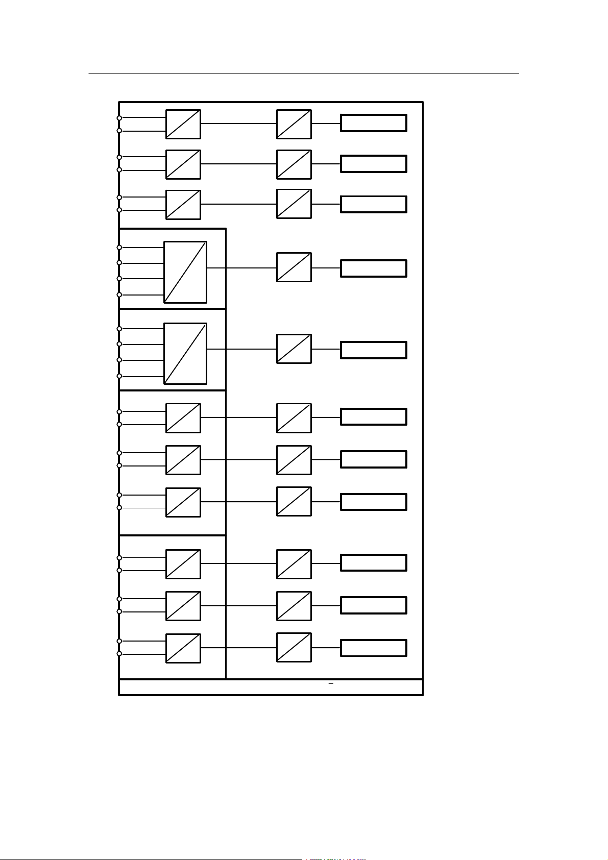
The input section contains the input functions for the 11 analog inputs, the 14 digital inputs, the
7 keys and the input part of the serial interface. (Not all analog and digital inputs can be used at
thesametime!)
In configuring mode hdEF the function of the slots 5 and 6 and thus the number of BE, BA, AA
and AE functions are defined. The input functions convert the process signals (analog and digital inputs) and the manual inputs (keys) into freely connectable data sources.
The output section contains the output functions for the 9 analog outputs, the 16 digital outputs,
the 5 displays, the 13 LEDs and the output part of the serial interface.
The output functions convert the freely connectable data sinks into process signals (analog and
digital outputs) and visual outputs (displays, LEDs).
The function section is between the input and output sections. It contains 109 arithmetic blocks,
in which 32 basic functions can be freely selected and 59 complex functions which can be used
with varying frequency. In addition adjustable parameters and a number of constants and fault
messages are available for free connection. The freely connectable parameters can be used for
the standard functions which have no parameters of their own whereas the complex functions
and some of the input and output functions have private (permanently assigned) parameters.
The basic functions have a standardized input/output format, i.e. they have a maximum 3 data
sinks (inputs) and 1 data source (output).
The complex functions and the input and output functions have different input/output formats,
i.e. the number of data sinks and sources depends on the function depth.
The parameters, constants and fault messages are data sources.
By configuring on the front module, the necessary functions are selected and defined (configuring mode FdEF and hdEF), wired (configuring mode FCon) and timed in the processing (configuring mode FPoS).
Wiring is absolutely free, i.e. any data source can be connected with any data sink. The operating effort is minimized by fading out the data sources and sinks of undefined function blocks
and assigning digital data sinks to digital data sources or analog data sinks to analog data
sources. In addition the data sinks not absolutely necessary for a function can be defaulted with
constants (example: the 3rd input of an adder is defaulted with 0.000).
SIPART DR24 6DR2410
C79000-G7476-C153-03
21

1 T echnical Description
1.5 Functional Description
1.5.1 Basic Structure
Manual
The connectable parameters and most private parameters can be set during operation in the
parameterization mode (online parameters). The other part of the private parameters is set offline in the configuring mode oFPA and CLP A.
The parameter and configuration data are stored in a non-volatile plug-in user program memory
with an EEPROM.
The cycle time in online operation depends on the scope of the user program and is a minimum
60 ms. About 2 ms are necessary on average per basic function, and about 5 ms per complex
function. The cycle time in offline operation is 100 ms.
Addition of the individual times gives the total cycle time t
which changes in 10 ms steps.
c
The current cycle time can be displayed during the lamp test (see chapter 5.1, page 169) by
additionally pressing tA1. dd3 shows the cycle time in ms.
On average you can reckon on 80 to 120 ms cycle time.
User program memory
Analog inputs
AE1...11
32 basic functions
can be used in 109 arithmetic blocks
Digital inputs
bE1...14
b**.F
59 complex functions with
private parameters can be
used in blocks
Keys
ta1...7
c**.F
d0*.F
h0*.F
with varying frequency
Connectable parameters
Write SES
Analog inputs
SA(E)1...16
Constants
Fault messages
Digital inputs
Sb(E)1...16
Operating modes: Process operation
Parameterization (Online)
AdAP Adaptation
Configuring (Offline)
oFPA Offline parameters
CAE4 Parameterize UNI-module for AE4
CAE5 Parameterize UNI-module for AE5
CLPA Clock parameters
hdEF Define hardware
FdEF Define functions
FCon Wire functions
FPoS Position functions
APSt Load factory setting (all preset)
Analog outputs
AA1...9
Digital outputs
bA1...16
Displays dA1, dA2,
dd1 to dd3
LEDs
L01...13
Read SES
Analog outputs
SAA1...16
Digital outputs
Sb(A)1...16
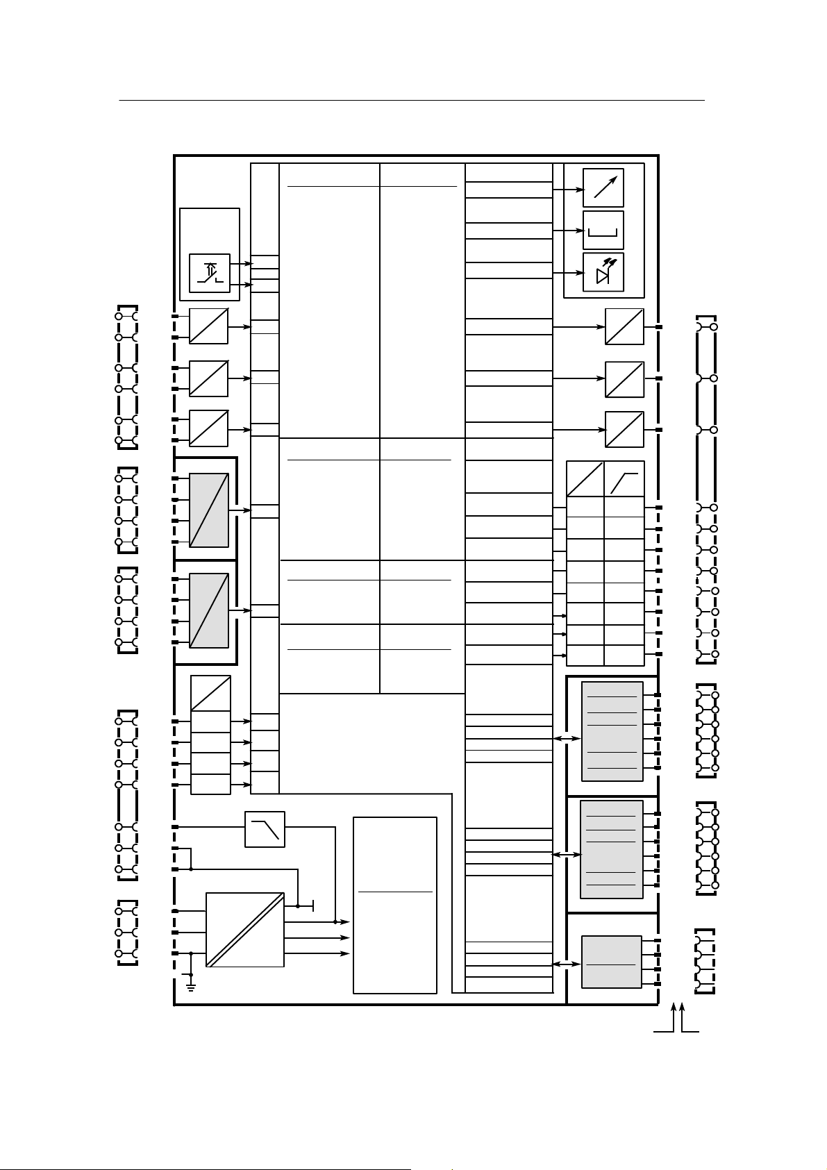
Figure 1--5 Block diagram of the SIPART DR24
22
SIPART DR24 6DR2410
C79000-G7476-C153-03

Manual
Functional overview SIPART DR24
1 Technical Description
1.5 Functional Description
1.5.1 Basic Structure
b = Basic function, blocks b
d = complex function, blocks d
Mathematical functions Func tion
D
AbS
Add
AMPL
CPt
div
FUL
FUP
LG
LinE
LN
MUlt
Pot
root
SUb
Comparison and switching functions Funct ion
D
AMPL
ASo
bSo
Cnt
CoMP
dEbA
LiMi
MASE
MiSE
MUP
Absolute value
Adder
Differential amplifier
P/T correction computer
Divider
Function transmitter (linear)
Function transmitter (parabola)
Decadic logarithmer
Linear equation
Natural logarithmer
Multiplier
Exponential function
Rooter
Subtractor
Differential amplifier
Analog switch over
Digital switch over
Demultiplexer
Comparator with hysteresis
Response threshold (dead band)
Limiter
Maximum selection
Minimum selection
Measuring point switch over
(analog)
c = complex function, blocks c
h = complex function, blocks h
Logical functions Fun ction
block
b
b
b
c
b
c
c
b
b
b
b
b
b
b
block
b
b
b
d
b
b
b
b
b
d
D
And
CoUn
dFF
Eor
nAnd
nor
or
SPR
tFF
tiME
Timer functions Func tion
D
AFi
Ain
bin
diF
dti
FiLt
PUM
tiME
AND
Counter
D--flip--flop
EXOR
NAND
NOR
OR
Split range
T--flip--flop
Timer (monoflop)
Adaptive filter
Integrator with analog input
Integrator with digital input
Differentiator
Dead time element
Filter (low pass)
Pulse width modulator
Timer (monoflop)
block
b
b
b
b
b
b
b
c
b
b
block
c
c
c
b
c
b
c
b
Memory functions Func tion
D
Ain
AMEM
bin
dFF
MAME
MiME
tFF
Program transmitter Func tion
D
CLoc Clock d
SIPART DR24 6DR2410
C79000-G7476-C153-03
Integrator with analog input
Analog memory
Integrator with digital input
D--flip--flop
Maximum memory (drag pointer)
Minimum memory (drag pointer)
T--flip--flop
block
c
b
c
b
b
b
b
block
Control functions Function
D
Ccn
CSE
CSi
K controller
S controller external feed
back
S controller internal feedback
block
h
h
h
23

1 T echnical Description
1.5 Functional Description
1.5.2 Input Functions
Manual
1.5.2 Input Functions
The following input functions are dealt with in detail in this chapter:
Analog inputs AE1 to AE11
Digital inputs BE1 to BE14
Data sinks bLS, bLPS, bLb
Keys tA1totA7
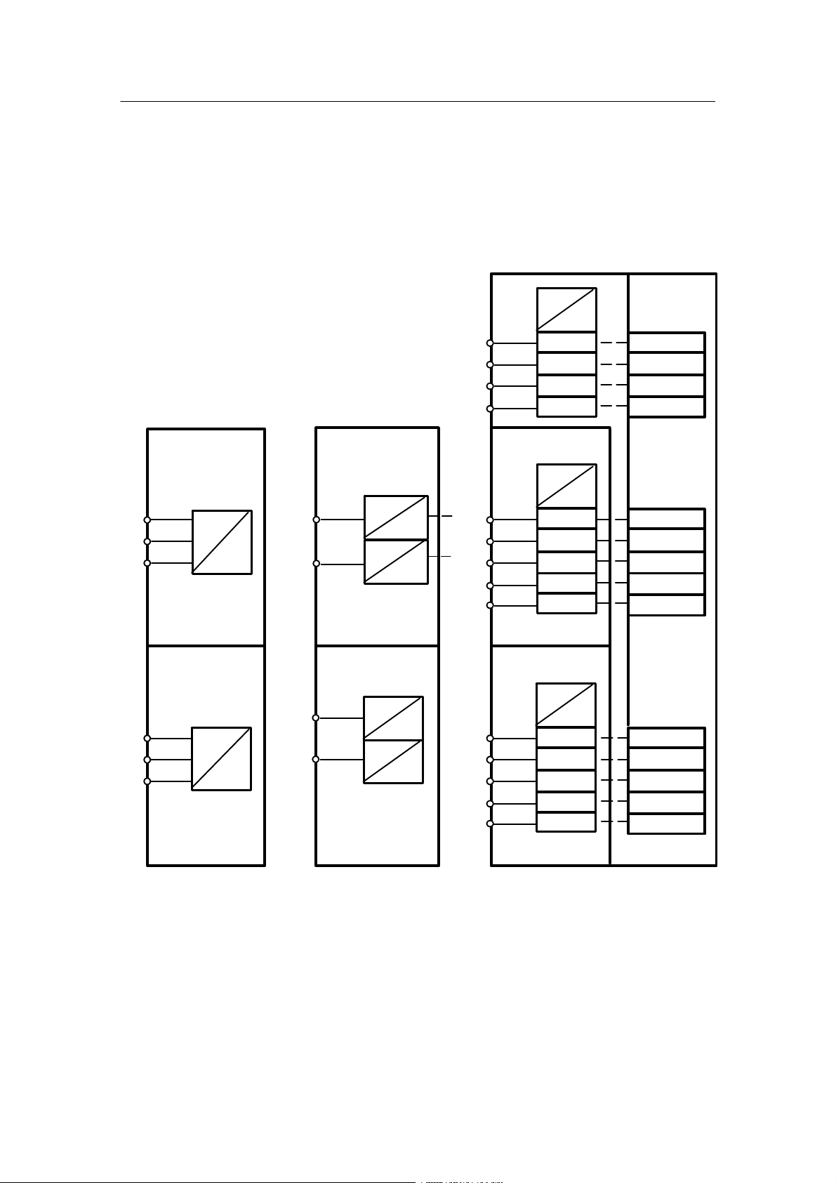
Analog inputs AE1 to AE11
The analog inputs AE1 to AE3 are located on the basic board and can be jumpered there.
Ranges: 1 V, 10 V, 20 mA. (The zero point can be selected via configuring mode hdEF (AE1 to
AE11).) The inputs AE4, AE5 are realized with a module card in slots 2 and 3. The inputs AE6
to AE8 are realized with a module in slot 6. The inputs AE9 to AE11 are realized with a module
in slot 5. Ranges same as AE1 to AE3.
The A/D converter inputs have a signal range from --5 % to +105 % or as an absolute value
--0.05 bis +1.05. If the evaluation of the inputs is to be changed you can switch the basic function “Multiply” (MULt) for weakening or strengthening the basic function and the basic function
“Linear equation” (LinE) to hide a range by configuring (see chapter 1.5.6, page 38).
The analog inputs AE* (*= 1 to 11) have a mains frequency suppression (configuring level
hdEF)
AEFr 50or60Hz
and the transmitter monitor AE1
to AE11 as a data source with a threshold at --3 % and
103%. The thresholds have a hysteresis of 1 %. The data source can be switched in FCon. The
fault message nAE
is set to low when the values exceed or drop below the limit. This signal
is also freely switchable in FCon.
24
SIPART DR24 6DR2410
C79000-G7476-C153-03
Manual
1 Technical Description
1.5 Functional Description
1.5.2 Input Functions
AE1+
AE1--
AE2+
AE2--
AE3+
AE3--
AE4
AE5
AE6+
AE6--
AE7+
AE7--
AE8+
AE8--
1/20
1/19
1/22
1/21
1/24
1/23
2/1
2/2
2/3
2/4
3/1
3/2
3/3
3/4
6/2
6/1
6/4
6/3
6/6
6/5
I,U
I,U
I,U
Slot 2
I
U
R
P
T
Slot 3
I
U
R
P
T
Slot 6
I,U
3AE
I,U
6DR2800-8A
I,U
oP6 = 3AE (hdEF)
∩
U
U
U
U
U
U
U
U
#
∩
#
∩
#
∩
#
∩
#
∩
#
∩
#
∩
#
AE1A ∩
AE2A ∩
AE3A ∩
AE4A ∩
AE5A ∩
AE6A ∩
AE7A ∩
AE8A ∩
Slot 5
AE9+
AE9--
AE10+
AE10- -
AE11+
AE11--
6/2
6/1
6/4
6/3
6/6
6/5
AE1...AE11 = 0 or 4 mA / AE4...AE5 = Uni_. or Uni
I,U
U
3AE
I,U
U
6DR2800-8A
I,U
U
oP5 = 3AE (hdEF)
Figure 1--6 Input function analog inputs
SIPART DR24 6DR2410
C79000-G7476-C153-03
∩
#
∩
#
∩
#
AE9A ∩
AE10A ∩
AE11A ∩
(hdEF)
25
1 T echnical Description
1.5 Functional Description
1.5.2 Input Functions
Manual
Digital inputs BE1 to BE14
The inputs BE1 to BE4 are located on the basic board. BE5 to 9 and 10 to 14 are connected to
the module 6DR2801--8C at the slots 5 or 6. The digital output modules 6DR2801--8E also contain another two digital inputs in addition to the outputs so that in this case the two digital inputs
BE5/BE6 or BE10/BE11 can be used.
The modules are assigned to the slots in the configuring mode hdEF.
24 V
Slot 5
3AA + 3BE
6DR2802--8B
BE5 BE5
5/1
5/2
5/3
6/1
6/2
6/3
24 V
BE6
BE7
oP5 = 3AA
(hdEF)
Slot 6
3AA + 3BE
6DR2802--8B
BE10
24 V
BE11
BE12
oP6 = 3AA
(hdEF)
5V
5V
5/1
5/6
6/1
6/6
Slot 5
4BA + 2BE
6DR2801-8E
BE6
oP5 = 4BA
(hdEF)
Slot 6
4BA + 2BE
6DR2801-8E
BE10
BE11
oP6 = 4bA
(hdEF)
24 V
24 V
24 V
24 V
5V
5V
5V
5V
1/15
1/16
1/17
1/18
5/1
5/2
5/3
5/4
5/5
6/1
6/2
6/3
6/4
6/5
BE1
BE2
BE3
BE4
Slot 5
6DR2801--8C
5BE
24 V
BE5
BE6
BE7
BE8
BE9
oP5 = 5BE
(hdEF)
Slot 6
6DR2801--8C
5BE
24 V
BE10
BE11
BE12
BE13
BE14
oP6 = 5bE
(hdEF)
5V
bE01 #
bE02 #
bE03 #
bE04 #
5V
bE05 #
bE06 #
bE07 #
bE08 #
bE09 #
5V
bE10 #
bE11 #
bE12 #
bE13 #
bE14 #
Figure 1--7 Input function digital inputs
26
SIPART DR24 6DR2410
C79000-G7476-C153-03

Manual
1 Technical Description
1.5 Functional Description
1.5.2 Input Functions
Data sinks bLS, bLPS, bLb
These sinks serve to block operation (bLb), the parameter and configuration adjustment (bLPS)
or just the configuration adjustment (bLS). At bLPS = high an error message no(dd1) PS(dd3) is
displayed when attempting to enter the parameterization mode.
At bLS = high no error message appears but the StrU level in the parameterization preselection
is hidden. The sinks bLS, bLPS and bLB can only be switched by the binary inputs BE1 to
BE14 (bE** = source) and the SES sources SbE1 to SbE8. When the CB time monitor responds or at Cbt = oFF, the SES sources connected with bLS, bLPS or bLb are set to low. See
also chapter 3.3.7, table 3--8, page 157.
The factory setting is low.
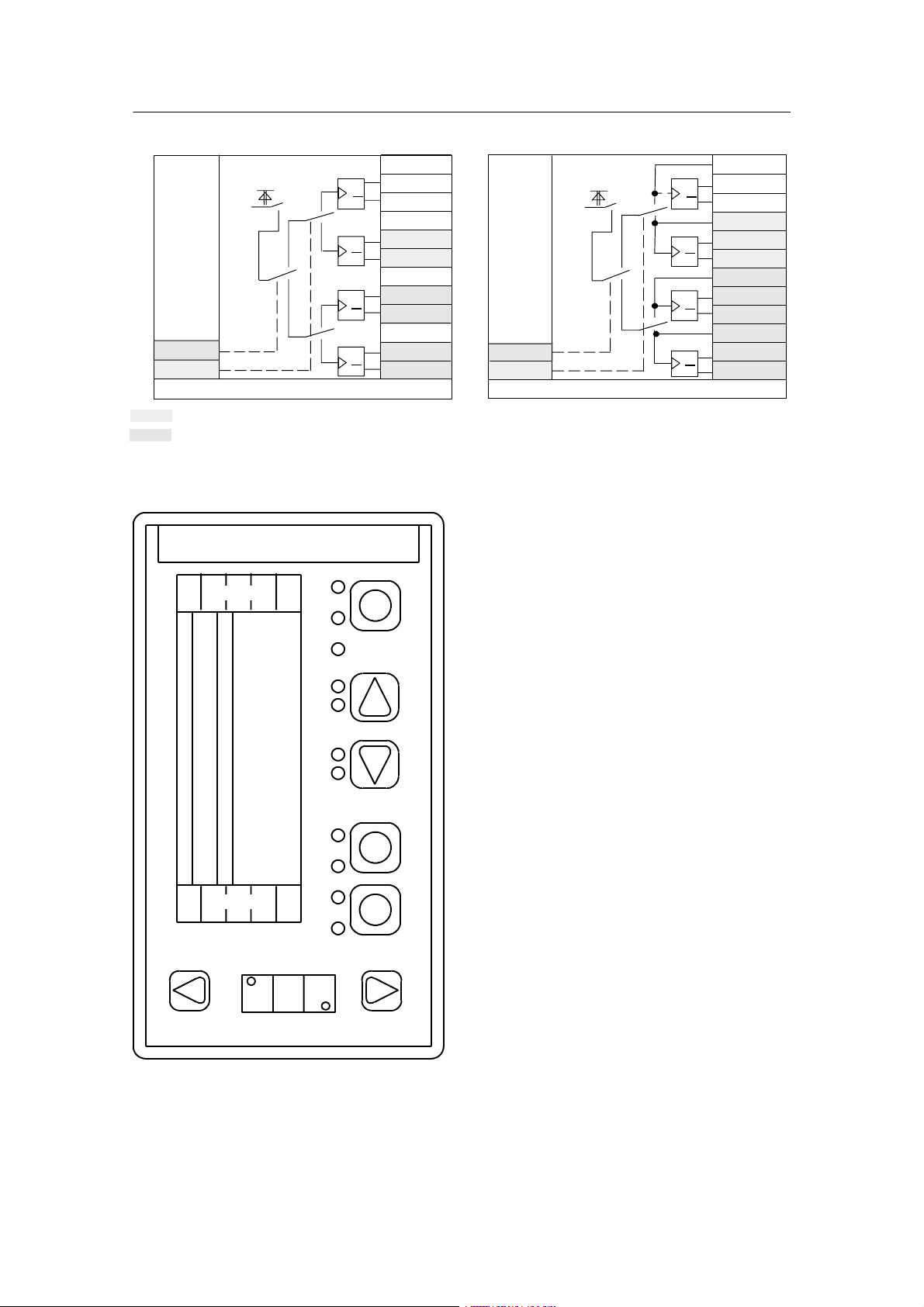
Keys tA1 to tA7
The keys (see figure 1--9, page 28) are available as key function tA*.1, tA*.2 or as switching
functions tA*.3, tA*.4 or tA*.5, tA*.6 (see figure 1--8, page 28). The keys are provided primarily
for incremental adjustment of the complex functions „Integrator with digital input” (bin) or controller inputsΔy. They can be switched by the control inputs tA*U/tA*M for quadruple applications whereby the status of the switched off outputs Q and Q
remains unchanged.
The key tA5 has no key output to other operating levels because of the universal function; i.e.
tA5.1 and possibly tA5.2 are not available. The outputs Q and Q
are switched at key 5 with the
low edge (release the key). “PS” flashes in dd3 after pressing tA5 continuously for about 5 s. All
keys lose their function in the process operating level when the display flashes in dd3.
You can now switch to the other levels (parametering, configuring). See chapter 3.3.1 (page
136), 3.3.2 (page 138) and 3.3, page 135.
When the function tA*.U is assigned „no” in the configuring mode hdEF, the shaded data
sources and sinks do not appear in the configuring mode FCon. Since the sink tA*.U is pre--assigned with low, the drawn switch position is active.
Restart conditions
Power on Q
bAtt = no
bAtt = YES
last status
0
Q
1
last status
SIPART DR24 6DR2410
C79000-G7476-C153-03
27
1 T echnical Description
1.5 Functional Description
1.5.2 Input Functions
Hi
gr
Lo
#tA5.M
Lo
#tA5.U
#tA5.U = no/YES/Four
arehiddeninFCon,if tA*.U = no
arehiddeninFCon,if tA*.U = no/YES
Figure 1--8 Input function keys
Q
Q
Q
Q
Q
Q
Q
Q
tA5.3#
tA5.5#
tA5.4#
tA5.6#
tA5.C#
tA5.E#
tA5.d#
tA5.F#
(hdEF)
Hi
gn
Lo
#tA1.M
Lo
#tA1.U
#tA1.U = no/YES/Four
tA2, 3, 4, 6, 7 functionally identical with tA1
Q
Q
Q
Q
Q
Q
Q
Q
Manual
tA1.1#
tA1.3#
tA1.5#
tA1.2#
tA1.4#
tA1.6#
tA1.A#
tA1.C#
tA1.E#
tA1.b#
tA1.d#
tA1.F#
(hdEF)
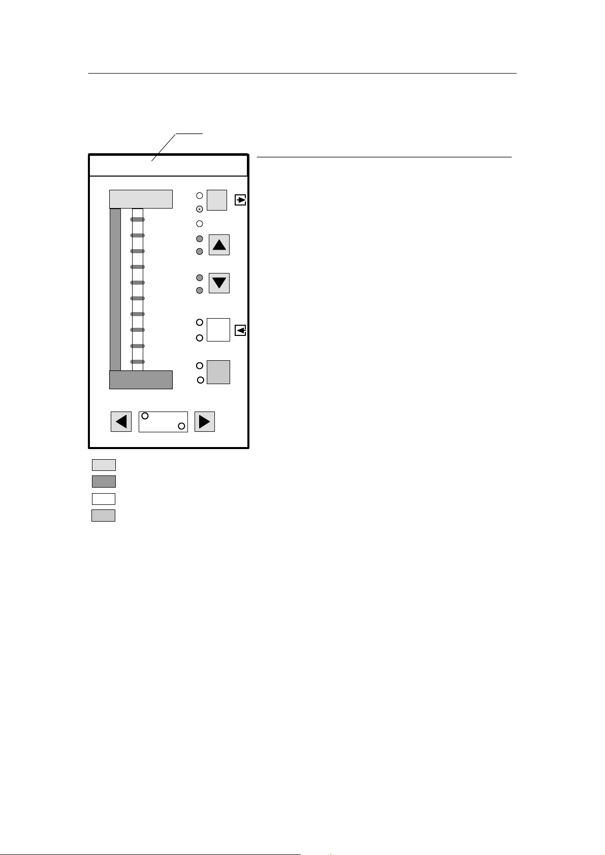
dA1
tA7
dd1
dd2
dA2/
L14
L13
dd3
L1
L2
L3
L4
L5
L6
L7
L8
L9
L10
L11
L12
tA1
tA2
tA3
tA4
tA5
tA6
Figure 1--9 Description of the displays, keys and LEDs on the front module of the SIPART DR24
28
SIPART DR24 6DR2410
C79000-G7476-C153-03
 Loading...