

Siemens SIPART DR22,6DR2210 User Manual
Manual Edition12/2006
Controller
SIPART DR22
6DR2210
sipart


SIPART DR22
6DR2210
Edition 12/2006
Manual
SIPART DR22 6DR2210
C79000-G7476-C154-03
1
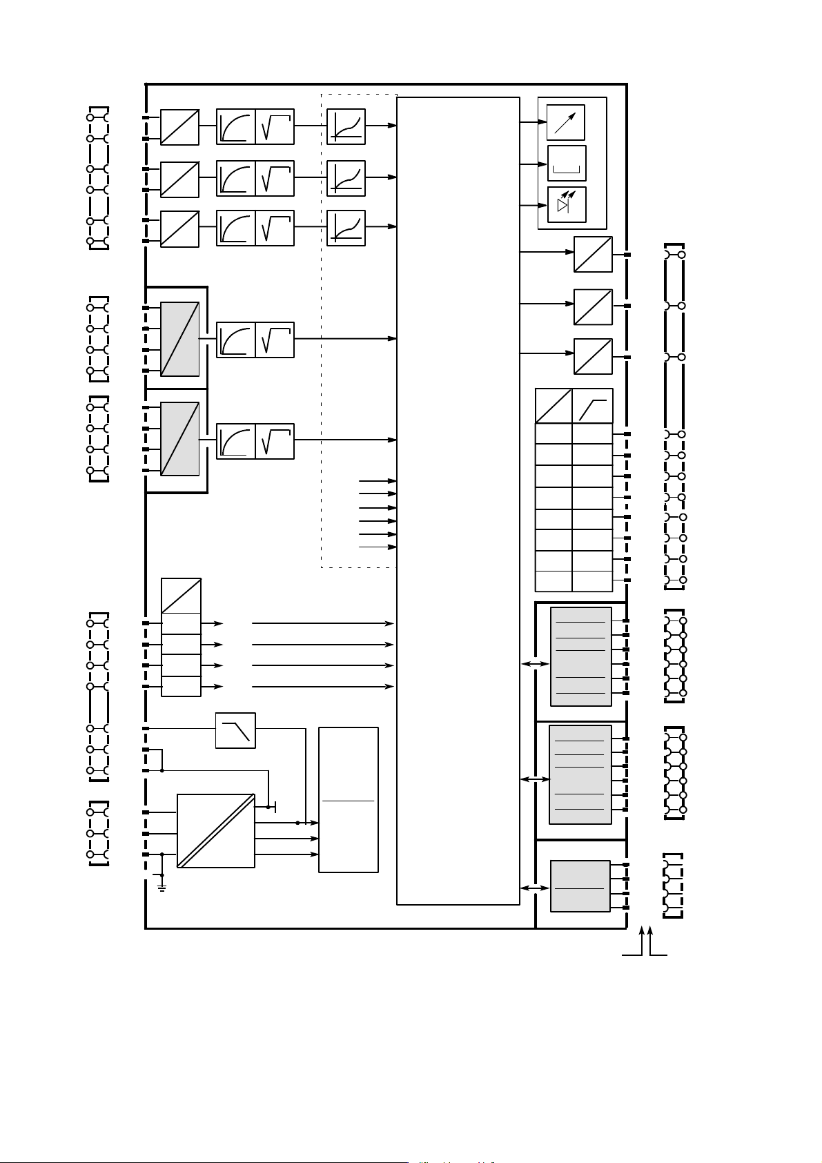
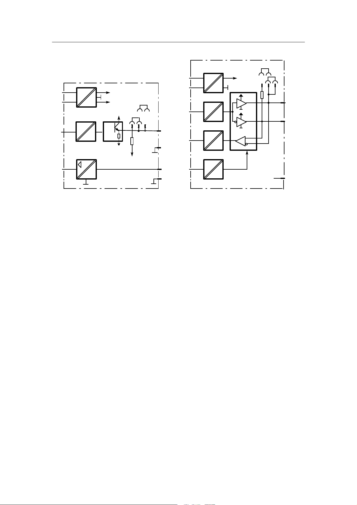
Block diagram
AE1
AE2
AE3
AE4
AE5
BE1
2
3
BE4
L+
+
-
+
-
+
-
Options
M
M
S5
1/20
1/19
1/22
1/21
1/24
1/23
2/4
2/3
2/2
2/1
3/4
3/3
3/2
3/1
1/15
1/16
1/17
1/18
1/3
1/2
1/1
N
PE
I,U
U
S6
I,U
U
S7
I,U
U
S8
I,U,R
UNI,
P,
T,
V
U
Slot 2
S9
I,U,R
UNI,
P,
T,
V
U
Slot 3
24 V
5V
S3
L
«
6DR2210-4 24 V UC
6DR2210-5 115/230 V AC switchable
bE01
bE02
bE03
bE04
I
–
S10
AE1A
t
S11
AE2A
t
S12
AE3A
t
S13
AE4A
t
S14
AE5A
t
M
+24V
+5V
U
REF
S20
S20
S20
drawn:
S4 = 0
at S4 = 1 freely
connectable
S212 to S217
FE7
FE8
FE9
FE10
FE11
FE12
User
program
memory for:
onPA on
AdAP line
oFPA
FdEF
FCon off
FPoS line
APSt
FPST
S15
Standard
FE1
settings
S16
Analog inputs
FE2
Assembly
S17
Slot 5 and 6
FE3
Digital inputs
Setpoint command
S18
Control algorithm
FE4
Y switching
Y display
S98
Analog outputs
FE5/6
Digital outputs
Limit value alarms
Restart
conditions
Serial interface
S0 to S4
S5 to S21,
S200 to S217
S22, S23
S24toS48,
S218 to S228
S49toS53
S54toS60
S61toS66
S67toS68
S69toS75,
S247 to S257
S76toS93,
S258 to S266
S94toS98,
S267 to S268
S99, S100
S101 to S107
F
r
o
n
t
0000
m
o
d
u
l
e
U
U
U
I
5V
24 V I
3AE
1AA y
hold
5BE
4BA24V
+2BE
2BA Rel.
3AO/3BE
Slot 6
3AE
1AA y
hold
5BE
4BA 24V
+2BE
2BA Rel.
3AO/3BE
Slot 5
RS 232
RS 485
PROFIBUS
Slot 4
Slot Terminal
1/12
1/13
1/14
1/4
1/5
1/6
1/7
1/8
1/9
1/10
1/11
6/6
6/5
6/4
6/3
6/2
6/1
Options
5/6
5/5
5/4
5/3
5/2
5/1
4/2
4/7
4/8
4/3
AA1
AA2
AA3
BA1
2
3
4
5
6
7
BA8
Options
2
SIPART DR22 6DR2210
C79000-G7476-C154-03

Manual
Classification of safety--related notices
This manual contains notices which you shouldobserve toensure your own personalsafety, as well
as to protect the product and connected equipment. These notices are highlighted in the manual
by a warning triangle and are marked as follows according to the level of danger:
DANGER
!
!
!
indicates an immenently hazardous situation which, if not avoided, will result in
death or serious inury.
WARNING
indicates a potentially hazardous situation which, if not avoided, could result in
death or serious injury.
CAUTION
used with the safety alert symbol indicates a potentially hazardous situation which,
if not avoided, may result in minor or moderate injury.
CAUTION
used without the safety alert symbol indicates a potentially hazardous situation
which, if not avoided, may result in property damage.
NOTICE
indicates a potential situation which, if not avoided, may result in an undesirable
result or state.
.
Copyright e Siemens AG 2006 All rights reserved
The reproduction, transmission or use of this docu-
ment or its contents is not permitted without express written authority. Offenders will be liable for
damages. All rights, including rights created by patent grant or registration of a utility model or design,
are reserved.
Siemens AG
Automation and Drives
Postfach 48 48
90437 NÜRNBERG
DEUTSCHLAND
NOTE
highlights important information on the product, using the product, or part of the
documentation that is of particular importance and that will be of benefit to the
user.
Disclaimer of Liability
We have checked the contents of this manual for
agreement with the hardware and software described. Since deviations cannot be precluded entirely,
we cannot guarantee full agreement. However, the
data in this manual are reviewed regularly and any
necessary corrections included in subsequent editions. Suggestions for improvement are welcomed.
e Siemens AG 2006
Technical data subject to change.
SIPART DR22 6DR2210
C79000-G7476-C154--03
3

Trademarks
SIMATICR,SIPARTR,SIRECR, SITRANSR registered trademarks of Siemens AG.
Third parties using for their own purposes any other names in this document which refer to trade-
marks might infringe upon the rights of the trademark owners.
4
SIPART DR22 6DR2210
C79000-G7476-C154-03

Manual Contents
Conents
Page
1 Technical Description 7...................................................
1.1 Safety notes and scope of delivery 7..................................................
1.2 Range of Application 8..............................................................
1.3 Design (Hardware) 9...............................................................
1.4 Function principle 12................................................................
1.4.1 Standard controller 12.................................................................
1.4.2 Description of the option modules 13....................................................
1.4.3 CPU self-diagnostics 20...............................................................
1.4.4 Data storage, User program memory 21.................................................
1.5 Functional description of the structure switches 22.......................................
1.5.1 Analog input signal processing permanently connected 22..................................
1.5.2 Analog input signal processing freely connected (S4 = 1) 25.................................
1.5.2.1 Arithmetic Ar1 to Ar6 27...............................................................
1.5.2.2 Function transmitter Fu1 and Fu2 27....................................................
1.5.2.3 Maximum value selection MA1 to MA3 27................................................
1.5.2.4 Minimum value selection Mi1 to Mi3 28...................................................
1.5.2.5 Correction computer for ideal gases rE1 28...............................................
1.5.2.6 Switch for analog variables AS1 to AS5 33...............................................
1.5.2.7 Comparator with adjustable hysteresis Co1, Co2 33........................................
1.5.2.8 AND NOT function (NAND) nA1, nA2 33.................................................
1.5.2.9 OR NOT function (NOR) no1, no2 33....................................................
1.5.3 Digital input signal processing 34.......................................................
1.5.3.1 Digital inputs BE1 to BE14 34..........................................................
1.5.3.2 Assignment and direction of effect of the digital inputs 35....................................
1.5.3.3 Linking the digital inputs BE1 bis BE14 to the control signals via the SES 35...................
1.5.3.4 Functional explanation of the digital control signals 39......................................
1.5.4 Controller types (S1, S49 to S53) 40.....................................................
1.5.4.1 General, recurrent functions 40.........................................................
1.5.4.2 S1 = 0: Fixed setpoint controller with 2 independent setpoints 48...........................
1.5.4.3 S1= 1: Fixed setpoint controller with 2 dependent setpoints 51.............................
1.5.4.4 S1 = 2: DDC fixed setpoint controller 52................................................
1.5.4.5 S1 = 3: Follow-up controller, synchronized controller, SPC-controller 58.....................
1.5.4.6 S1 = 4: commanded ratio controller 64.................................................
1.5.4.7 S1 = 5: Cascade control 69..........................................................
1.5.4.8 S1 = 6: Ratio-cascade control 74......................................................
1.5.4.9 S1 = 7/8: Override control 77...........................................................
1.5.4.10 S1 = 9: Process display 83...........................................................
1.5.4.11 S1 = 10: Fixed setpoint controller with 1 setpoint (control system coupling) 84.................
1.5.4.12 S1 = 11: Follow-up controller without Int/Ext switching (control system coupling) 85.............
1.5.4.13 S1=12: Double fixed setpoint/follow-up controller 86......................................
1.5.5 Control algorithm, parameter control, adaptation 89........................................
1.5.5.1 Control algorithm 89..................................................................
1.5.6 Controller output structures (S2, S61 to S68) 99...........................................
1.5.6.1 S2 = 0: Continuous (K) controller 99...................................................
1.5.6.2 S2 = 1: Three-position step (S) -controller with internal feedback 104.........................
1.5.6.3 S2 = 2: Three-position step (S) -- controller with external feedback 107.......................
1.5.7 Analog output signal processing (S69 to S75, S247 to S257) 120..............................
1.5.8 Digital output signal processing (S76 to S93 and S258 to S266) 121...........................
1.5.9 Limit value alarms (S94 to S100, S267 to S268) 124........................................
1.5.10 Restart conditions (S99, S100) 126.......................................................
1.5.11 Serial interface and PROFIBUS-DP (S101 to S107) 126.....................................
1.6 Technical Data 127...................................................................
1.6.1 General data 127......................................................................
1.6.2 Standard Controller 129................................................................
1.6.3 Technical data of the options modules 133.................................................
SIPART DR22 6DR2210
C79000-G7476-C154-03
5

2 Installation 143.............................................................
2.1 Mechanical Installation 143............................................................
2.2 Electrical Connection 143.............................................................
2.2.1 Connection standard controller 147.......................................................
2.2.2 Wiring of option modules 150............................................................
2.2.3 Alternative connection for I- and U-input 158...............................................
2.2.4 Connection of the interface 163..........................................................
3 Operation 167..............................................................
3.1 Process operation 167................................................................
3.2 Selection level 169...................................................................
3.3 Configuring level (parameterization and structuring mode) 172..............................
3.3.1 Paramterization 172...................................................................
3.3.2 Parameterization mode onPA (online parameters) 173.......................................
3.3.3 Parameterization mode AdAP (Adaptation) 175.............................................
3.3.4 Structuring mode oFPA (offline Parameters) 182............................................
3.3.5 Structuring mode PASt (parameter control) 184.............................................
3.3.6 Structuring mode StrS (structure switches) 186.............................................
3.3.7 Structuring mode FdEF (define functions) 201..............................................
3.3.8 Structuring mode FCon (connect functions, connection) 202..................................
3.3.9 Structuring mode FPoS (position functions) 205............................................
3.3.10 Structuring mode FPSt (Functions Preset, factory setting) 209................................
3.3.11 Structuring mode APSt (All Preset, factory setting) 210......................................
3.3.12 Set structuring mode CAE4/CAE5 -- UNI module(s) 211.....................................
3.3.12.1 Measuring range for mV (SEnS=Mv.) 212.................................................
3.3.12.2 Measuring range for U, I (SEnS=Mv.) 212.................................................
3.3.12.3 Measuring range for thermocouple with internal reference point (SEnS=tc.in) 213................
3.3.12.4 Measuring range for thermocouple with external reference point (SEnS=tc.EH) 213..............
3.3.12.5 Measuring range for PT100-4-wire and PT100-3-wire connection (SEnS=Pt.3L/PT.4L) 213........
3.3.12.6 Measuring range for PT100-2-wire connection (SEnS=Pt.2L) 214.............................
3.3.12.7 Measuring range for resistance potentiometer
(SEnS=r._ for R < 600 W, SEnS=r. for R< 2.8 kW) 214......................................
ManualContents
4 Commissioning 215........................................................
4.1 Adapting the controller direction of effect to the controlled system 215........................
4.2 Setting the split range outputs and the actuating time in K-controllers (S2 = 0) 217.............
4.3 Adaptation of the S-controller to the actuating drive 218....................................
4.4 Setting the filter and the response threshold 219..........................................
4.5 Automatic setting of control parameters 220..............................................
4.6 Manual setting of the control parameters 224.............................................
4.7 Manual setting of the control parameters 225.............................................
5 Maintenance 227...........................................................
5.1 General information and handling 227...................................................
5.2 Spare parts list 231...................................................................
6 Ordering data 233..........................................................
7 Application examples for configuring the controller 235.......................
8 Configuring tool 241........................................................
9 Explanation of abbreviations 253............................................
Index 259........................................................................
6
SIPART DR22 6DR2210
C79000-G7476-C154-03

Manual 1 Technical Description
1.1 Safety notes and scope of delivery
1 Technical Description
1.1 Safety notes and sco p e of delivery
!
D Scope of delivery
When the controller is delivered the box contains:
1 Controller as ordered
1 three-pin plug at 115/230 V AC or special plug at 24 V UC
2 Clamps, pluggable
1 Assembly and installation instructions
Order number C79000-M7474-C38
WARNING
This device is electrically operated. When operating electrical
equipment, certain parts of this equipment automatically carry
dangerous voltages. Failure to observe these instructions could
therefore lead to serious injury or material damage. Only properly
trained and qualified personnel are allowed to work on this
equipment. This personnel must be fully conservant with all the
warnings and commissioning measures as described in this user’s
guide.
The perfect and safe operation of this equipment is conditional upon
proper transport, proper storage, installation and assembly as well as
on careful operation and commissioning.
D Basic equipment
The following variants of the SIPART DR22 are available:
Order number Power Supply
6DR2210-4
6DR2210-5
D Option modules
Signal convertors have separate ordering and delivery items. For handling reasons basic
equipment and signal convertors which were ordered at the same time may be delivered by
separate mail.
D Documentation
This user’s guide is available in the following languages:
English C79000-G7476-C154
German C79000-G7400-C154
SIPART DR22 6DR2210
C79000-G7476-C154-03
24 V UC
115/230 V AC, switchable
7

1.2 Range of Application
Manual1 Technical Description
D Subject to change
The user’s guide has been compiled with great care. However, it may be necessary within
the scope of product care to make changes to the product and its operation without prior
notice which are not contained in this user’s guide. We are not liable for any costs ensuing
for this reason.
1.2 Range of Application
The SIPART DR22 is a digitally operating device in the top class range. Its program memory
contains a large number of prepared function blocks for calculating, controlling, regulating in
technical processes which the user can implement without programming knowledge and
additional tools.
In addition a robust adaptation procedure is available in this device which makes it much easier
to commission even critical controlled systems. The controller determines the optimized control
parameters independently on request without the user being expected to have any prior
knowledge of how the control loop may respond. The applied procedure is suitable for systems
with compensation and aperiodic transient behavior; even greater dead times are taken into
account.
For more complicated applications the fixed connection of the individual functions can be
canceled in the input range and replaced by a free structuring. The user can easily add extra
analog function blocks and connect them to each other and to the interfaces of the input range
with the software. This achieves optimum adaptation even to complex problems.
The named programming possibilities guarantee a great flexibility in the use of the controller
and allow fast, easy adapting of the device to the problem so that the SIPART DR22 can be
used universally for control jobs in processing engineering, e.g. as
-- fixed setpoint controller for one, two or three-component control, optionally with two
setpoints
-- DDC fixed setpoint controller for one-, two- or three-component control
-- follow-up controller (synchronized controller, SPC controller) with internal/external switching
-- fixed or commanded ratio controller with Internal/External switching
-- cascade controller (double controller)
-- ratio-cascade controller (double controller)
-- override controller with Min or Max selection of the manipulated variable (double controller)
-- double controller with two independent control channels
The extensive hardware equipment of the instrument by which numerous interfaces are
available for connecting the field cables is of advantage for the universal utilization. The
instrument can also be connected to master systems via a plug-in serial interface or operated
and monitored centrally by a Personal Computer.
The SIPART DR22 can be used alternatively as a continuous controller with a current output
signal or as a three-position step controller for controlling electric motor drives without changing
the hardware equipment.
8
SIPART DR22 6DR2210
C79000-G7476-C154-03

Manual 1 Technical Description
1.3 Design (Hardware)
1.3 Design (Hardware)
The process controller SIPART DR22 has a modular structure and is therefore maintenance
friendly and easy to convert and retrofit. Other signal convertors can be installed in the generously equipped, fully functional standard controller to expand the range of application. These
modules are inserted in backplane slots of the enclosed instrument (Fig. 1-2, page 11).
The standard controller consists of
-- the front module with the control and display elements
-- the main board with CPU and terminal strips
-- the plastic casing with an interface board
-- the power supply unit.
The electrical connections between the modules are made by an interface board screwed into
the casing. The main board is pushed into rear slot 1 and locked. It holds a 10-pin and a 14-pin
terminal strip to which all inputs and outputs of the standard controller are connected. Five other
slots can be equipped with option modules if the number of terminals to the process available in
the standard controller are not sufficient for the planned task.
The standard controller always has three permanently installed analog inputs (AE) with electronic potential isolation which can be wired alternatively with standardized voltage signals
(0/0.2 to 1 V or 0/2 to 10 V) or current signals (0/4 to 20 mA). There are also four digital inputs
(BE, 0/24 V) and eight digital outputs (BA, 0/24 V, 50 mA) which can be used for different functions depending on the configuration.
The SIPART DR22 also has three analog outputs (AA) which can all supply a current signal
from 0 to 20 mA or 4 to 20 mA and be assigned to different variables.
A short-circuit-proof L+--output (DC 24 V, 100 mA) is available for supplying transmitters.
The power supply unit is located in a fully enclosed metal casing and is screwed tightly to the
plastic casing of the controller. This power supply is available in two different versions so that
two types of SIPART DR22 are available:
6DR2210-4 for power supply connection UC 24 V
6DR2210-5 for power supply connection AC 230 V, switchable to AC 115 V
Many applications can be implemented with the three permanently available analog inputs of
the standard controller alone. Two additional input modules can be inserted in slots 2 and 3 for
complex jobs or for the connection of other input signals. These input modules are available in
addition to for processing normalized current and voltage signals for the direct connection of
resistance thermometers Pt100 and all common thermocouples and resistance sensors or
potentiometers. In addition a module with 3 analog inputs (equipment as in the standard
controller) can be inserted in slots 5 and 6. This increases the number of inputs to a total of 11.
Slot 4 serves to accommodate an interface module (SES) with V.28-point-pointoutput or
SIPART bus interface for serial communication with a master system. A PROFIBUS interface
module can be equipped optionally here.
SIPART DR22 6DR2210
C79000-G7476-C154-03
9
1.3 Design (Hardware)
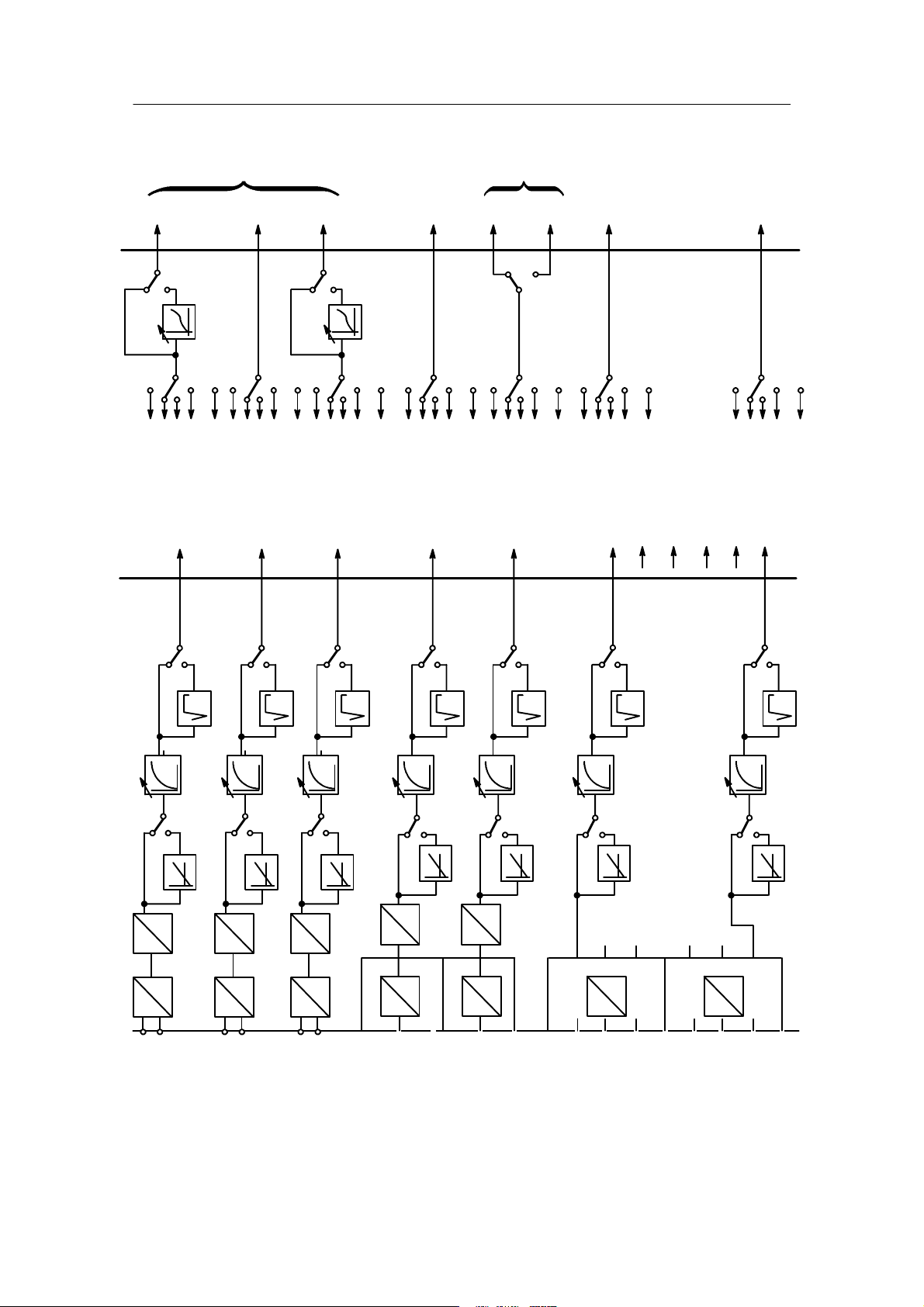
The slots 5 and 6 can accommodate signal convertors of different functions and can be
equipped optionally with modules for expanding digital inputs or digital outputs.
The following assemblies are possible:
2 relays
4 digital outputs/2 digital inputs
5 digital inputs
3 analog outputs/3 digital inputs
1 analog output with digital fault output (y
function) with remote supply
hold
3 analog inputs
1
Manual1 Technical Description
3
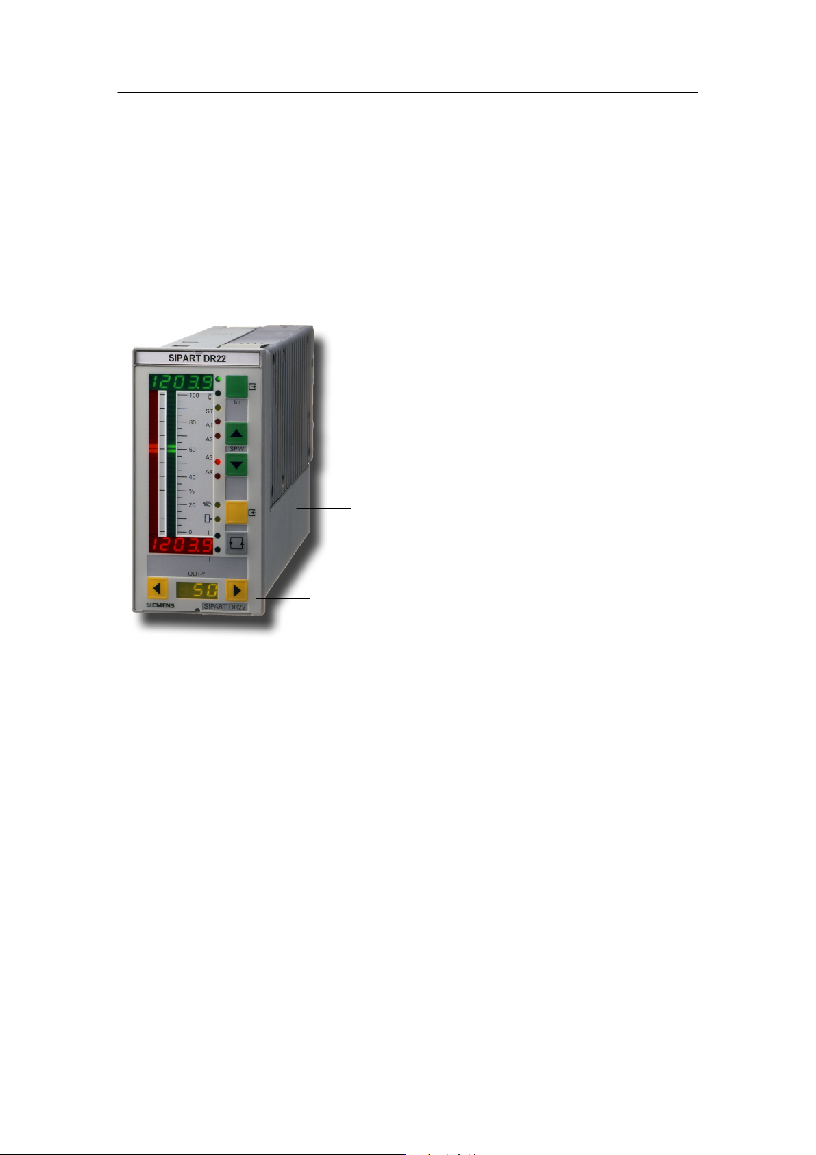
Figure 1-1 Front view of the SIPART DR22
2
1 Power supply unit
2Casing
3 Front module
10
SIPART DR22 6DR2210
C79000-G7476-C154-03
Manual 1 Technical Description
1
12
11
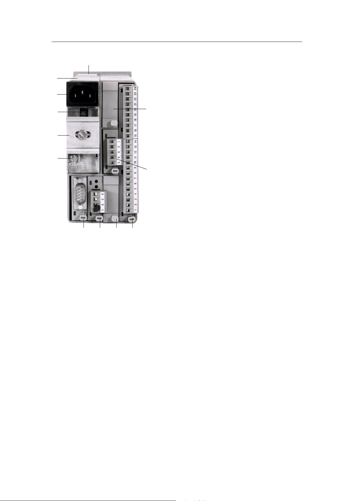
Legend:
10
2
9
8
3
1 PE conductor -- contact spring
2Slot6
3Slot5
4 Slot 1 (basic board)
5Slot2
6Slot3
7 Slot 4 (SES: RS 232/
RS 485, Profibus DP)
8 Grounding screw
9 DIN rail (delivered with the
interface relay)
10 Selector switch Mains voltage
11 Mains plug
12 Power supply unit
1.3 Design (Hardware)
7 6 5 4
Figure 1-2 Rear view of the SIPART DR22
SIPART DR22 6DR2210
C79000-G7476-C154-03
11

1.4 Function principle
1.4.1 Standard controller
Manual1 Technical Description
1.4 Function principle
1.4.1 Standard controller
The standard controller consists of three function blocks:
-- Power supply unit
-- Front module
-- Main board
Power supply unit
Primary clocked power supply plug with high efficiency for AC 115/230 V (switchable) or for UC
24 V. It generates the secondary internal supply voltages +24 V and +5 V from the power
supply. The metal body is mounted on PE conductors (protection class I). The power supply
and internal supply voltages are isolated from each other by safe separation by a protective
shield. The internal supply voltages are functional extra-low voltages due to overvoltage cutoff
in the event of an error. Since no other voltages are generated in the instrument, these
statements apply for all field signal cables (used standards, see chapter 1.6, page 127). A total of
450 mA are available for the outputs L+, AA and BA due to the design for a high power output.
Front module
The front module contains the control and display elements and the appropriate trigger components for the displays.
All display elements are designed in LED technology which provides a longer service life and
higher light density as well as a good viewing angle. The control elements are short-stroke
switches with a tangible ”pressure point” and high return force.
Main board
The main board contains the field signal conditioning of the standard controller, the CPU
(Central Processing Unit) and the connections (through the interface board) to the module slots.
The field signals are fed through protective circuits for external static or dynamic overvoltages
and then adapted to the signal levels of the CPU by the appropriate circuits. This adaptation is
performed for the analog inputs, the analog outputs and the digital outputs by modern thick-film
circuits.
The microcontroller used has integrated AD- and DA converters and operates with 32k batterybacked RAM. The user-specific configuration is stored in an user program memory with a serial
4k EEPROM. When replacing the main board the user memory can be plugged from the old
onto the new module. The whole CPU is designed in C-MOS technology.
A process image is generated at the start of every routine. The analog and digital inputs and
actuation of the front buttons is included and the process variables received from the serial
interface are accepted. All calculations are made with these input signals according to the
configured functions. Then the data are output to the display elements, the analog outputs and
the digital outputs as well as storage of the calculated variables on standby for the serial
interface transmitter. The interface traffic runs in interrupt mode.
12
SIPART DR22 6DR2210
C79000-G7476-C154-03

Manual 1 Technical Description
1.4.2 Description of the option modules
1.4 Function principle
A large number of prepared functions for controlling processing plants as well as machines and
apparatus is stored in the set value memory of the SIPART DR22. The user programs the
instrument himself by selecting the desired functions by setting structure switches. The total
functioning of the instrument is given by the combination of the individual structure switches.
Programming knowledge is not necessary for the settings. All settings are made without an
additional programming unit exclusively through the front panel of the SIPART DR22 or through
the serial interface. The job-specific program written in this way is saved in the non-volatile user
program memory.
1.4.2 Description of the option modules
The following option modules are described in this chapter
6DR2800-8A Module with 3 AE, U- or I-input
6DR2800-8J I/U module
6DR2800-8R R module
6DR2800-8V UNI module
6DR2805-8A Reference junction terminal
6DR2805-8J Measuring range for TC, internal connector
6DR2801-8D Module with 2 BA (relays)
6DR2801-8E Module with 2 BE and 4 BA
6DR2801-8C Module with 5 BE
6DR2802-8A Analog output module with y-hold function
6DR2802-8B Module with 3AA and 3BE
6DR2803-8P Serial interface PROFIBUS-DP
6DR2803-8C Serial interface RS 232 / RS 485
6DR2804-8A Module with 4 BA relays
6DR2804-8B Module with 2 BA relays
6DR2800-8A Module with 3 AE, U- or I-input
D Inputs for current and voltage
To expand the analog inputs.
For a description of the module and technical data, see chapter 1.6.2, page 129 (Inputs standard
controller).
SIPART DR22 6DR2210
C79000-G7476-C154-03
13

1.4 Function principle
1.4.2 Description of the option modules
Manual1 Technical Description
6DR2800-8J I/U module
D Input variables current 0/4 to 20 mA or voltage 0/0.2 to 1 V or 0/2 to 10 V
The input amplifier of the module is designed as a differentiating amplifier with jumperable gain
for 0 to 1 V or 0 to 10 V input signal. For current input signals the 49.9 Ω 0.1 % impedance is
switched on by plug-in bridges on the module. The start value 0 mA or 4 mA or 0 V or 0.2 V
(2 V) is defined by configuration in the standard controller. The differentiating amplifier is
designed for common mode voltages up to 10 V and has a high common mode suppression.
As a result it is possible to connect the current inputs in series as for electrical isolation when
they have common ground. At voltage inputs this circuit technique makes it possible to
suppress the voltage dips on the ground rail by two--pole wiring on non floating voltage supplies.
We refer to an electronic potential isolation.
6DR2800-8R R module
D Input for resistance or current potentiometer
Potentiometers with rated values of 80 Ω to 1200 Ω can be connected as resistance
potentiometers. A constant current of Is = 5 mA is fed to the potentiometer wiper. The wiper
resistance is therefore not included in the measurement. Resistances are switched parallel to
the potentiometer by a slide switch on the module and a rough range selection made. Range
start and end are set with the two adjusting pots on the back of the module.
This fine adjustment can be made by the displays on the front module (with the appropriate
structuring). For adjustment with a remote measuring instrument, the analog output can be assigned to the appropriate input.
The external wiring must be changed for resistance potentiometers which cannot withstand the
5 mA wiper current or which have a rated resistance
> 1kΩ. The constant current is then not
fed through the wiper but through the whole resistance network of the potentiometer. A voltage
divider measurement is now made through the wiper. Coarse adjustment is made by a remote
parallel resistor to the resistance potentiometer.
This module can also be used as a current input with adjustable range start and full scale. The
load is 49.9 Ω and is referenced to ground.
6DR2800-8V UNI module
D Direct connection of thermocouple or Pt100 sensors, resistance of mV transmitters
Measured value sensors such as thermocouples (TC), resistance thermometers Pt100 (RTD),
resistance potentiometers (R) or voltage transmitters in the mV range can be connected directly. The measuring variable is selected by configuring the controller in the HdeF level
(AE4/AE5); the range and the other parameters are set in the CAE4/CAE5 menu. The sensorspecific characteristics (linearization) for thermocouples and Pt100 resistance thermometers are
stored in the contoller’s program memory and are automatically taken into account. No settings
need to be made on the module itself.
14
SIPART DR22 6DR2210
C79000-G7476-C154-03

Manual 1 Technical Description
1.4.2 Description of the option modules
1.4 Function principle
The signal lines are connected by a plug terminal block with screw terminals. When using thermocouples with internal reference junction terminal, this terminal block must be replaced by the
terminal 6DR2805-8A. With the measuring for TC, internal connector 6DR2805-8J in place of
the terminal block, the measuring range of the direct input (0/20 to 100 mV) can be extended to
0/2upto10Vor0/4upto20mA.
The UNI module operates with an AD converter with 18 bit resolution. The measuring inputs
and ground of the standard controller are electrically isolated with a permissible common mode
voltage of 50 V UC.
6DR2805-8A reference junction terminal
D Terminal with internal reference junction terminal for thermocouples
This terminal is used in connection with the UNI module for temperature measuring with thermocouples at an internal reference junction terminal. It consists of a temperature sensor which
is preassembled on a terminal block and plated to avoid mechanical damage.
6DR2805-8J measuring for TC, internal connector
D measuring for TC, internal connector for current 0/4 to 20 mA or voltage 0/2 to 10 V
The measuring for TC, internal connector is used in connection with the UNI module to
measure current orvoltage. The input variable is reduced to 0/20 to 100 mV by a voltage divider
or shunt resistors in the measuring for TC, internal connector.
Wiper resistors with 250 Ω or 50 Ω are available optionally at 2 different terminals for 0/4 to
20 mA signals.
The electrical isolation of the UNI module is retained even when the measuring for TC, internal
connector is used.
6DR2801-8D Module with 2 BA relays
D Digital output module with 2 relay contacts
To convert 2 digital outputs to relay contacts up to 35 V UC.
This module is equipped with 2 relays whose switching contacts have potential free outputs.
The RC combinations of the spark quenching elements are respectively parallel to the rest and
working contacts.
In AC consumers with low power the current flowing through the capacitor of the spark
quenching element when the contact is open may interfere (e.g. the hold current of some
switching elements is not exceeded). In this case the capacitors (1 μF) must be removed and
replaced with low capacitance capacitors.
The 68 V suppressor diodes parallel to the capacitors act additionally to reduce the induced
voltage.
SIPART DR22 6DR2210
C79000-G7476-C154-03
15

1.4 Function principle
1.4.2 Description of the option modules
Manual1 Technical Description
!
WARNING
The relays used on the digital output module are designed for a
maximum rating up to UC 35 V. The same applies for the air and creep
lines on the circuit board. Higher voltages may therefore only be
switched through appropriately approved series connected circuit
elements under observance of the technical data and the pertinent
safety regulations.
6DR2801-8E Module with 2 BE and 4 BA
D Digital signal module with 2 digital inputs and 4 digital outputs
The module serves to extend the digital inputs and digital outputs already existing in the standard controller.
The inputs are designed for the 24 V logic and are non-floating. The functions are assigned to
the inputs and outputs by the configuration of the controller.
The digital outputs are short-circuit-proof and can drive commercially available relays or the
interface relays 6DR2804--8A/8B directly.
6DR2801-8C Module with 5 BE
D Digital input module with 5 digital inputs
The module serves to extend the digital inputs already existing in the standard controller.
The inputs are designed for the 24 V logic and are non-floating. The function is assigned to the
input by the configuration of the controller.
6DR2802-8A Analog output module with y-hold function
For auxiliary control device function when servicing and for extending the analog outputs AA1 to
AA3 existing in the standard controller.
Can be inserted in slot 5/6, S22/S23=4 to be set in the structure mode StrS,
Start value of the outputs S72/S249 can be set in StrS.
The y
module contains a microprocessor which maintains serial data communication with the
hold
processor on the main board through the Rxd/Txd lines. The processor feeds the U/I converter
and the CPU fault message output St
through its analog output. The module can be externally
supplied through an auxiliary voltage input which is OR--linked with the controller power supply.
The analog output of the module is freely available.
-- y
-function
hold
If data communication to the y
processor is interrupted, the analog output receives its last
hold
value. The processor reads the current variable first when data traffic is recovered. The output current is maintained if:
16
SIPART DR22 6DR2210
C79000-G7476-C154-03

Manual 1 Technical Description
1.4.2 Description of the option modules
1.4 Function principle
-- the self diagnostics of the CPU (see chapter 1.4.3, page 20) responds.
-- the supply voltage of the SIPART DR22 fails and the y
-- all modules except the power supply unit are removed (if the y
-module is powered externally.
hold
module is powered
hold
externally).
-- the y
module is removed (Attention: electrostatically sensitive module! Observe the
hold
safety precautions!), if it is powered externally (error message on the front module
oP. *.6 Err/oP.*.5, see chapter 5, page 227). *.6 Err/oP.*.5, see chapter 5).
In this way it is possible to perform all maintenance work right up to replacing the instrument
whilst maintaining the controller controlled variable.
Handling during module replacement, see chapter 5 ”Maintenance”.
Fault message output
-- S t
This digital output is always high when there is no error and becomes low in the event of an
error. It responds when:
-- the self diagnostics of the CPU (see chapter 1.4.3, page 20) responds.
-- the controller power supply fails,
-- the Y
module is removed,
hold
-- the main board is removed.
6DR2802-8B Module with 3AA and 3BE
To extend the analog outputs (0/4 to 20 mA) and digital inputs
can be inserted in slot 5: AA7, AA8, AA9 BE5, BE6, BE7
and in slot 6: AA4, AA5, AA6 BE10, BE11, BE12
6DR2803-8P Serial interface PROFIBUS-DP
The module 6DR2803-8P is a PROFIBUS-DP interface module with RS 485 driver and electrical isolation to the controller. It operates as an intelligent converter module and adapts the private SIPART to the open PROFIBUS-DP protocol.
This optional card can be inserted in all SIPART-DR controllers in slot 4. The following settings
must be made with the appropriate configurations for the serial interface:
-- Interface on
-- Even parity
-- LRC without
-- Baud rate 9600
-- Parameters/process values writable (as desired)
-- Station number according to selection 0 to 125
Make sure that the station number is not assigned double on the bus. The PROFIBUS module
serves to connect the SIPART controllers to a master system for control and monitoring.
In addition the parameters and configuring switches of the controller can be read and written.
Up to 32 process variables can be selected and read out cyclically by configuration of the
PROFIBUS module.
SIPART DR22 6DR2210
C79000-G7476-C154-03
17

1.4 Function principle
1.4.2 Description of the option modules
Manual1 Technical Description
The process data are read out of the controller in a polling procedure with an update time <
300 ms. If the master writes process data to the slave, these become active after a maximum 1
controller cycle.
The description and the controller base file (*.GSD) can be downloaded from Internet under
www.fielddevices.com
.
A technical description including the controller base file (*.GSD) is available for creating a master-slave linking software for interpreting the identifications and useful data from and to the SIPART controller.
The programs SIPART S5 DP and S7 DP are offered for certain hardware configurations.
6DR2803-8C Serial interface RS 232 / RS 485
D Serial interface for RS 232 or RS 485 with electrical isolation
Canbeinsertedinslot4.
For connecting the controller SIPART DR22 to a master system for control and monitoring. All
process variables can be sent, the external setpoint, tracking variable, operating modes, parameters and configurations sent and received.
The interface traffic can take place as follows:
RS 232 as point-to-point connection
SIPART Bus
The SIPART bus is no longer available. Therefore please implement multipoint
connections via RS 485 or PROFIBUS DP.
RS 485 As a serial data bus with up to 32 users.
The interface module 6DR2803-8C offers electrical isolation between Rxd/Txd and the controller. Switching can be performed between RS 232, SIPART bus and RS 485 with a plug-in
bridge.
A detailed technical description of the telegram traffic is available for creating an interface software.
18
SIPART DR22 6DR2210
C79000-G7476-C154-03
Manual 1 Technical Description
1.4.2 Description of the option modules
Txd
24 V
0V
+7.5 V
-7.5 V
+7.5V
+1
-7.5 V
RS 232
SIPART
bus
24 V
0V
Txd
2
Txd
7
Rxd
+7.5 V
1.4 Function principle
RS 485 + 150R
+7.5 V
+7.5 V
RS 485
8
3
Rxd/
Txd A
Rxd/
Txd B
Rxd
-1
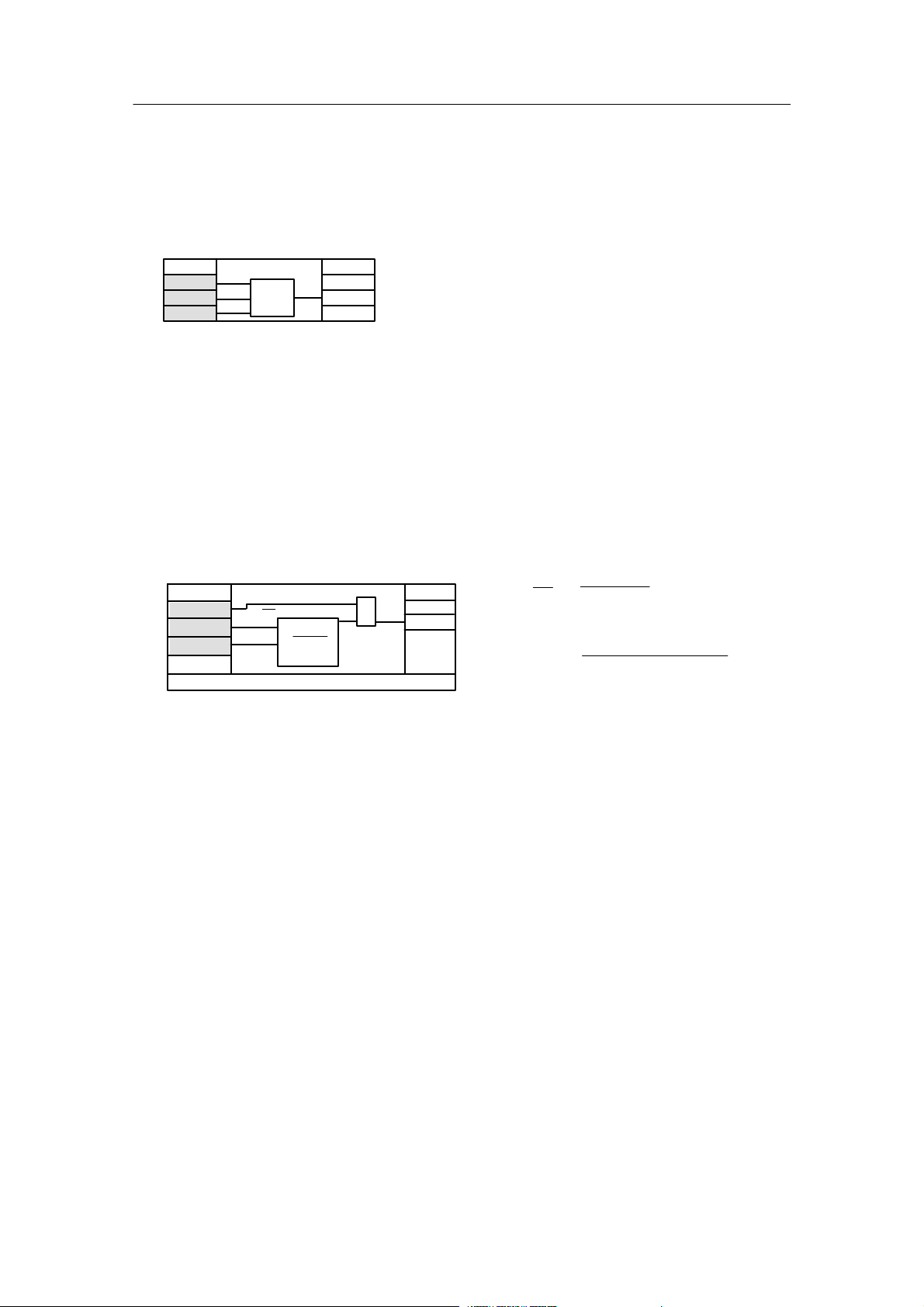
Figure 1-3 Block diagram serial interface
for RS 232 / SIPART BUS
-7.5 V
Other connections: NC
3
Rxd
8
Rxd/
Txd
NC2, 7
Other connections: NC
Figure 1-4 Block diagram serial interface for
RS 485
6DR2804-8A Module with 4 BA relays
6DR2804-8B Module with 2 BA relays
D Interface relay module with 2 or 4 relays
To convert 2 or 4 binary outputs to relay contacts up to 230 V UC.
The module can be snapped onto a mounting rail on the back of the controller. The mounting
rail is delivered with the interface relay module.
One or two relay modules with 2 relays each are installed depending on the version. Every relay
has a switching contact with spark quenching in both switching branches. In AC consumers with
a very low power, the current flowing (e.g. hold current in contactors) through the spark quenching capacitor (33nF) when the contact is open interferes. In this case they should be replaced
by capacitors of the same construction type, voltage strength and lower value.
The switching contact is fed to the plug terminals with 3 poles so that rest and working circuits
can be switched. The relays can be controlled directly from the controller’s digital outputs by
external wiring.
SIPART DR22 6DR2210
C79000-G7476-C154-03
19

1.4 Function principle
1.4.3 CPU self-diagnostics
Manual1 Technical Description
!
WARNING
The relays used on the interface relay module are designed for a
maximum rating of AC 250 V in overvoltage class III and
contamination factor 2 according to DIN EN 61010 Part 1.
The same applies for the air and creep lines on the circuit board.
Resonance increases up to twice the rated operating voltage may
occur when phase shift motors are controlled. These voltages are
available at the open relay contact. Therefore such motors may only
be controlled under observance of the technical data and the
pertinent safety conditions via approved switching elements.
1.4.3 CPU self-diagnostics
The CPU runs safety diagnostics routines which either can only after a reset or cyclically. The
CPU is familiar with two different types of reset.
-- Power on reset
Power-On-Reset always takes place when the 5-V supply drops below 4.45 V, i.e. the power
supply is interrupted for longer than specified in the technical data.
All parameters and configurations are reloaded from the user program memory into the
RAM.
At S100 = 1 the digital x-display flashes as indication after a Power-On-Reset, it is
acknowledged by the Shift key (12).
Flashing is suppressed by S100 = 0.
-- Watch dog reset
When a watch-dog-reset occurs the parameters and configurations from the user program
memory are reloaded into the RAM. The current process variables and the status signals are
read out of the RAM for further processing.
There are no flashing signals on the front module.
CPU-tESt appears in the digital displays dd1 and dd2 for a maximum 5 s after every reset.
Every error detected by the self-diagnostics leads to a flashing error message on the digital displays dd1 and dd2 with defined states of the analog and digital outputs. The fault message output St
of the y
module becomes low. The reactions listed in the table are only possible of
hold
course (since this is a self-test) if the errors occur in such a way that the appropriate outputs or
the front module can still be controlled properly or the outputs themselves are still functioning.
There are other error messages for the input range which indicate defective structurings within
this range (see chapter 1.5.6 ”Error messages”, page 99).
In addition error messages are output in the adaptation (see chapter 3.3.2
”Parameterization mode AdAP”, page 173).
The digital displays flash in the case of error messages.
20
SIPART DR22 6DR2210
C79000-G7476-C154-03

Manual 1 Technical Description
g
/
sages
gofg
Errorcause/
CPU
RAM
0last
0mA00
0
A
y
0mA00
0
memor
y
p
g
)
1
)
municatio
n
cyclic0
operatingwith
tin
g
matchtheplugged
1.4 Function principle
1.4.4 Data storage, User program memory
1.4.4 Data storage, User program memory
All data are written in the RAM first and then transfered to the user program memory
(EEPROM) when returning to the process operation mode (manually or via the SES).
Writing time
The writing time after leaving the parameterization and configuring modes is up to 30 s. Then
the data are stored in a non-volatile memory.
Error messages of the CPU
Reactions
Error
y
mes-
sa
dd1
dd2
CPU
Err
MEM
Err
es
Monitoring
EEPROM,
EPROM
User
program
memor
Monitoring
time
Power
On-Reset
Watch
Dog-Reset
Power
On-Reset
Watch
Dog-Reset
St
0
hold
AA4/7
with
U
last
value
last
value
-module
H
AA4/7
without
U
H
0mA
last
value
0mA
last
value
when
storing
continues operating with current
oP.5.*.
1)
oP.*.6.
1
Data communication
μP-slot 5
Data communication
μP-slot 6
cyclic 0
cyclic 0
pulled
last
value
defective,
pulled
0mA
undefined
1)
Also double error display oP.5.6 possible,
* means digit dark.
2)
At BE5 to 9 and BE10 to 14 the effect of the digital inputs (after inversion) are set to 0 in the event of an error.
Standard
controller
AA1
to 3
0m
data
continues
operating with
current data
Options
BA1
to 8
BA9
to 12
0 0 0
continues
operating with
current data
last
state
or undefined
continues
operating
with
current
data
2)
BA13
to 16
continues
operating
with
current
data
last
state
or undefined
Primary
Error cause
Remedy
Monitored components of the CPU
defective/change
main board
User program
memory not plugged
or defective/plug or
change
Monitored components of the CPU
defective/change
main board
User program
memory not plugged
or defective/plug or
change
Option not plugged,
defective or setting in
hdEF oP5 does not
match the plugged
option.
Plug option or replace
or correct oP5
Option not plugged,
defective or setting in
hdEF oP5 does not
match the plugged
option.
Plug option or replace
or correct oP6
3)
3)
Table 1-1 Error message of the CPU
SIPART DR22 6DR2210
C79000-G7476-C154-03
21

1.5 Functional description of the structure switches
1.5.1 Analog input signal processing permanently connected
Manual1 Technical Description
1.5 Functional description of the structure switches
(S0 to S107, S200 to S268)
In the factory setting (setting when the device is delivered) most of the structure switches are
set to 0. This corresponds to the most usual setting of the individual functions so that only few
structure switches need to be set selectively during commissioning. However, it is recommendable to compare the individual structure switch settings with the task.
With structure switch S0 the user program can be identified by a number from 1 to 254 in the
structuring mode Strs. The setting 0 corresponds to the factory setting and is regenerated automatically in the APSt function (All Preset). All changes in parameters or structures in relation to
the factory setting automatically set S0 from 0 to 1.
The structure switches S1 and S2 are fundamentally significant. With S1 the controller type is
set and thus the processing of command variable, main controlled variable and auxiliary controlled variables up to control difference generation determined. With S2 the controller output
structure is set and thus the processing of the automatic-, manual-, safety- and follow--up variables as well as the manipulated variable output determined as a K- or S-output.
1.5.1 Analog input signal processing permanently connected
(S3 to S21, S200 to 205)
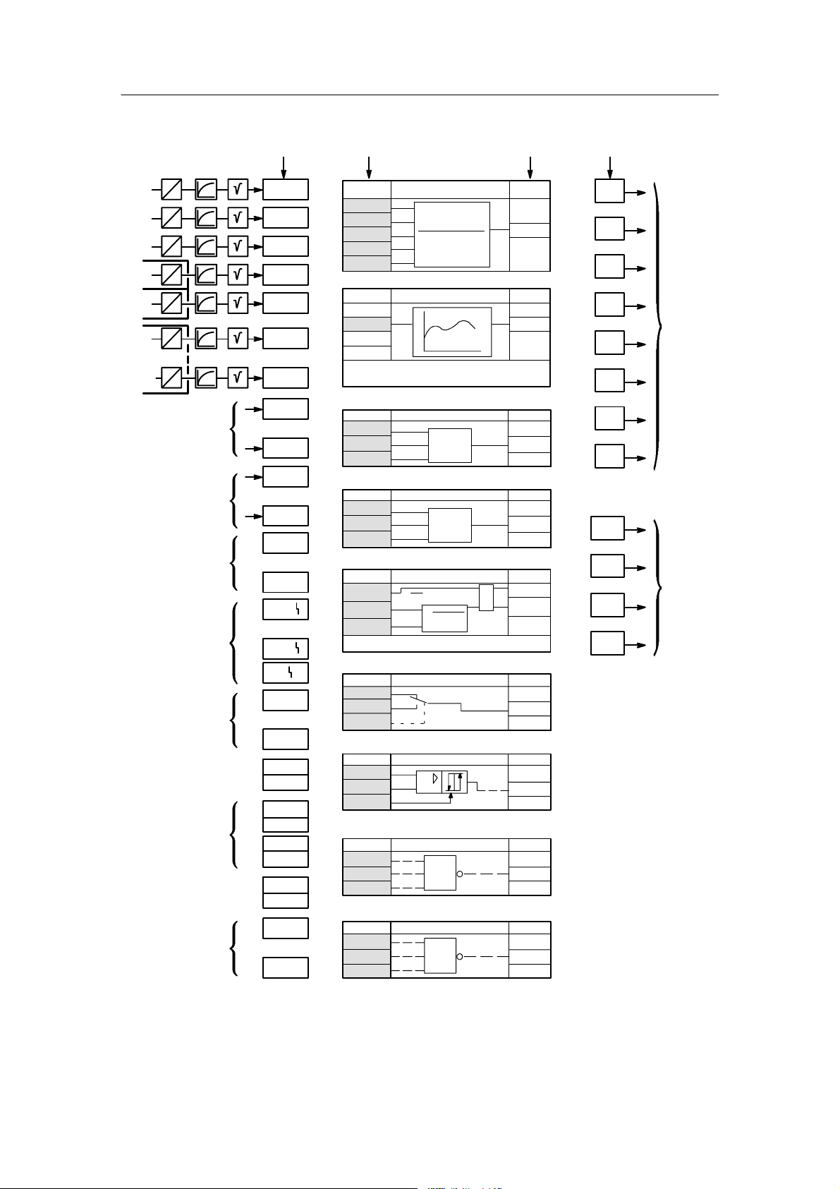
In the structure switch setting S4=0 the analog input range is permanently connected
(see figure 1-5, page 24). With S4=1 the permanent connection is canceled and converted into
a freely connectable input range (see chapter 1.5.2, page 25).
Every one of the maximum 11 analog inputs is fed through an AD converter which performs the
50 or 60 Hz interference suppression by averaging over 20 or 16 2/3 ms. After this the signal
range 0 to 20 mA or 4 to 20 mA is normalized to 0 to 100% calculated value per channel with
S5 to S9 or S200 to S205.
At the same time it is decided with S5 to S9 or S200 to S205 whether operation is to take place
with or without range monitoring (transmitter fault). The monitor signals per channel on dropping
below --2.5 % or exceeding +106.25 % with a hysteresis of 0.25 % to the digital x and w display.
By an OR link of all single messages the group transmitter fault MUF is formed which can be
assigned to the digital outputs and negated optionally (see chapter 1.5.8, page 121). Only the
analog inputs selected with the transmitter fault monitor are monitored, displayed on the front
panel (the appropriate position stays dark in the case of analog inputs not selected with transmitter fault) and signaled with the OR link. The error message is acknowledged with the Shift
key (12). The fault message signal via the OR link is available until the appropriate analog inputs are back in the working range.
After the range monitoring the 11 analog inputs are fed through a 1st order filter which can be
set by the parameters tF1 to tFb in the range of oFF, 0.1 to 1000 s in the parameterization
mode onPA. The factory setting is 1 s.
With S10 to S14 or S206 to S211 every channel can now be root extracted optionally. After root
extraction, the 11 analog inputs are available for further processing as AEA1 to AEbA.
22
SIPART DR22 6DR2210
C79000-G7476-C154-03

Manual 1 Technical Description
1.5.1 Analog input signal processing permanently connected
1.5 Functional description of the structure switches
The function inputs FE1 and FE3 are preceded by a linearizer which enables non-linear process
variables to be displayed physically correctly (for operating method see chapter 1.5.2, page 25)
function block Fu, setting of the 13 vertex values, see chapter 1.5.4, figure 1-19, page 45 to
figure 1-23, page 46).
The outputs of the analog inputs AE1A to AEbA are now assigned to the function inputs FE1 to
FE12 by the structure switches S15 to S19 or S212 to S217. The outputs AE1A to AEbA and
the function inputs FE1 to FE12 are available for the assignment to analog outputs, the limit
value alarm and the parameter control and can be read through the SES. With this input
structure most control tasks can be solved in connection with the different controller types and
controller output structures.
SIPART DR22 6DR2210
C79000-G7476-C154-03
23
1.5 Functional description of the structure switches
1.5.1 Analog input signal processing permanently connected
Manual1 Technical Description
see fig. 1-24 (pg. 48) to
fig. 1-44 (pg. 83)
FE1
FE2
see fig. 1-50
(pg. 90)
FE3
see fig. 1-58 (pg. 102) to
fig. 1-62 (pg. 109)
FE4
FE5Zy
N
FE6
R
y
FE7
FE12
function inputs
S20
1
0
--1 .1
to 11.1
S15
0
o%
1
2
AE1A
AE2A
0
3
11
1
2
...
o%
AE3A
AEbA
AE1A
AE2A
S21
1
0
--1 .3
to 11.3
S16
3
11
...
AE3A
AEbA
0
o%
S17
3
1
11
2
...
AE1A
AE2A
AE3A
AEbA
0
o%
S18
0
3
1
11
2
AE1A
AE2A
o%
AE3A
AEbA
1, 2
0
S2
...
S19
3
1
11
2
...
AE1A
AE2A
AE3A
AEbA
0
o%
S212
3
1
11
2
...
AE1A
AE2A
AE3A
AEbA
0
o%
S217
3
1
11
2
...
AE1A
AE2A
AE3A
AEbA
connectable
AE7A
AE8A
AE1A
S4 = 1 drawn
at S4 = 1 freely
AE2A
AE3A
AE4A
AE5A
AE6A
AE9A
AEAA (AE10A)
AEbA (AE11A)
Outputs of the
tF1
A
+
1/20
analog outputs
AE1
S5
0, 1
AE1A
S10
0
1
AE2A
S11
0
1
AE3A
S12
0
1
AE4A
S13
0
1
AE5A
S14
0
1
AE6A
S206
0
1
AEbA
(AE11A)
S211
0
1
...
tF2
S6
2, 3
0, 1
4bis20mA
D
D
A
U
--
1/19
I, U
+
1/22
AE1
U
--
1/21
I, U
tF3
S7
2, 3
0, 1
4to20mA
D
A
U
+
--
1/23
1/24
AE1
I, U
tF4
S8
2, 3
0, 1
4to20mA
D
A
U
Slot 2
AE4
I, U, R,
P, T
tF5
S9
2, 3
0, 1
4to20mA
D
A
U
Slot 3
AE5
I, U, R,
P, T
tF6
...
S200
2, 3
4to20mA
2, 3
0, 1
...
4bis20mA
D
Slot 6
AE6
I, U
AE7
I, UAAE8
Slot 5
I, U
AE9
tFb
S205
2, 3
0, 1
4to20mA
D
AE10
I, UAAE11
I, U
I, U
Figure 1-5 Analog input signal processing permanently connected (S4 = 0)
24
SIPART DR22 6DR2210
C79000-G7476-C154-03

Manual 1 Technical Description
1.5.2 Analog input signal processing freely connected (S4 = 1)
1.5 Functional description of the structure switches
1.5.2 Analog input signal processing freely connected (S4 = 1)
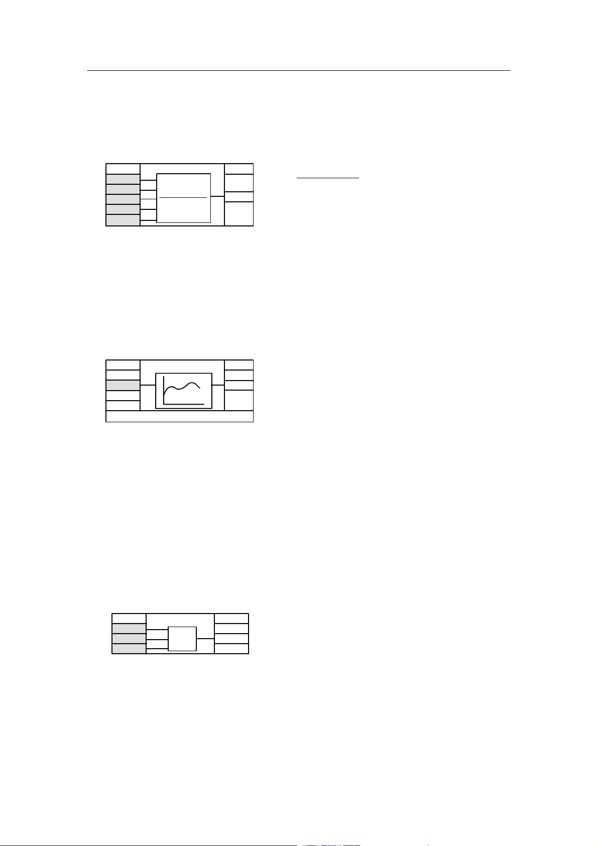
The structure switch setting S4=1 cancels the permanent connection at S4=0 in the analog input range and replaces it with a freely connectable input range. The freely connectable input
range basically represents a multifunctional unit, configuring takes place according to the same
rules.
Up to the outputs AE1A to AEbA (AE11A), the signal processing is identical to that described in
chapter 1.5.1, page 22. The function inputs FE1 to FE12 also operate in the same way with the
difference that FE5 (follow-up input) and FE6 (position feedback input) can be used in parallel
and with the difference that FE5 (follow--up input) and FE6 (position feedback input) can be
used in parallel and connected with different signals.
Nine different function blocks which occur with different frequency can now be connected
absolutely freely between the outputs AE1A to AEbA and the function inputs FE1 to FE12. The
outputs AE1A to AEbA represent data sources whilst the function inputs FE1 to FE12 are data
sources. Parallel to the outputs, 15 connectable linear parameters are arranged with a setting
range of -1.999 to 19.999 (corresponding to -199.9 % to 1999.9 %), a number of normal
constants as well as other variables gained from the controller as data source.
The function blocks have a different number of inputs (data sinks) and 1 output each (data
source) depending on the function depth.
The function blocks ”function transmitter” and ”correction computer” have assigned parameters
which can be set in the structuring mode oFPA. The connectable parameters P1 to P15 are set
in the parameterization mode onPA.
By structuring on the front module the necessary functions are selected or defined (structuring
mode FdEF), connected (structuring mode FCon) and correctly positioned in time in the cycle
(structuring mode FPoS), see chapter 3.3.7, page 201 to 3.3.9, page 205. Connection is absolutely free, i.e. any data source can be connected with any data sink. The operating effort is
minimized by fading the data sources and sinks from undefined function blocks. In addition the
data sinks which are not obliagatory for a function are pre--occupied by constants which can be
overwritten. The inputs pre--occupied with ncon (not connected) are absolutely essential for the
function and must be connected. This very variable connection facility in the analog input range
also enables complex control tasks to be solved.
No distinction is made between analog and digital signals. Digital inputs have a threshold value
of 0.5. Digital outputs supply a value of 0 % (0) or 100 % (1).
SIPART DR22 6DR2210
C79000-G7476-C154-03
25
1.5 Functional description of the structure switches
1.5.2 Analog input signal processing freely connected (S4 = 1)
Data sources Data sinks Data sources Data sinks
Manual1 Technical Description
AE1
AE2
AE3
AE4
AE5
AE6
AE11
Connectable
parameters
Constants
Digital inputs
Fault message
AE1.A
AE2.A
AE3.A
AE4.A
AE5.A
AE6.A
AEb.A
P01
.
.
.
P15
--1,0
.
.
.
1.05
BE01
.
.
.
BE09
AE1
.
.
.
AE5
Ar .F
Ar .1
Ar .2
Ar .3
Ar .4
Ar .5
Fu .F
Fu .1
Parameter:
Vertex value at -10, 0, 10 to 90, 100, 110
MA .F
MA .1
MA .2
MA .3
Mi .F
Mi .1
Mi .2
Mi .3
rE1 .F
rE1 .1
rE1 .2
rE1 .3
Parameter. tA, tE, PA, PE
Ar1 to Ar6
E1
E2
E1 · E2+E3-E4
E3
E4
E5
Fu1, Fu2
E
A
MA1 to MA3
E1
E2
E3
Mi1 to Mi3
E1
E2
E3
rE1
ΔP
E2
f(E2·E3)
E3
E5
Max
Min.
A
A
E
A
A
x
A
nr
Ar .6
nr
Fu .2
nr
MA .4
nr
Mi .4
nr
rE .4
FE1
FE2
FE3
FE4
FE5
FE6
FE7
FE8
FE9
FE10
FE11
FE12
Analog
signals
Analog
or
digital
signals
Alarms A1 to A4
AE
A1
.
.
.
AS .F
AS .1
AS .2
AS .3
AS1 to AS5
E1
E2
E3
A
A4
Status message
Setpoints w1/w2
Manipulated
variable y *)
Serial analog value
Int1
Int2
SPI1
SPI2
SP1
SP2
yI
yII
SAA1
.
.
.
SAA4
Co .F
Co .1
Co .2
Co .3
nA .F
nA .1
nA .2
nA .3
no .F
no .1
no .2
no .3
Co1, Co2
E1
+
E2
-
E3
nA1, nA2
E1
E2
E3
no1, no2
E1
E2
E3
&
≥1
A
H
A
A
Figure 1-6 Analog input signal processing freely connectable (S4=1)
26
nr
AS .4
nr
Co .4
nr
nA .4
nr
no .4
SPI 1/2: internal setpoint
SP 1/2: active setpoint
*) y1: Manipulated value
*) y2: Manipulated value
controller 1/2
controller1/2
y controller 1
y controller 2
(for S1 = 12)
SIPART DR22 6DR2210
C79000-G7476-C154-03
Manual 1 Technical Description
1.5.2 Analog input signal processing freely connected (S4 = 1)
1.5 Functional description of the structure switches
The individual function blocks are described below.
1.5.2.1 Arithmetic Ar1 to Ar6
Ar1toAr6
ncon
ncon
0.000
0.000
1.000
Ar .F
Ar .1
Ar .2
Ar .3
Ar .4
Ar .5
E1
E2
E1 · E2+E3-E4
E3
E4
E5
E5
Figure 1-7 Function block Arithmetic Ar1 to Ar6
-- With this function block the four basic arithmetic functions are implemented with appropriate
assignment of inputs 0 and 1 respectively. The preset E3=E4=0, E5=1 gives A = E1×E2.
-- Typical process-technical applications are dosing or evaluation (E1×E2), range fade-outs
(E1×E2+E3) or differentiations (E3 - E4).
nr
A
Ar .6
E1 · E2 + E3 - E4
A=
E5
E5 is limited to values ≥0.5 %.
1.5.2.2 Function transmitter Fu1 and Fu2
Fu1, Fu2
Fu .F
ncon
Fu .1
-10, 0, 10 bis 90, 100, 110oFPA
E
nr
AA
Fu .2
E
A=f(E)
Figure 1-8 Function block function transmitter
The function transmitter assigns every value of the input variable E in the range from -10 % to
+110 % an output variable A in the range from -199,9 % to +199,9 % with the function entered
by the user: A = f(E). The function is entered by the parameters ”vertex value 1 to 13” for -10 %
to +110 % of E in intervals of 10 %. Parabolae are set by the computing program between
these vertex values which interlink tangentially the vertex values so that a constant function is
produced. The vertex values at -10 % and +110 % of E are required for the overflow. The last
rise remains constant in the case of further overmodulation of E. When used as a linearizer for
the displays, the linearization function is entered by the 13 vertex values so that the series
circuiting of the sensor function gives a linear equation with the linearization function
(see chapter 1.5.4, figure 1-20 to figure 1-23, page 46).
1.5.2.3 Maximum value selection MA1 to MA3
MA1.F to MA3.F
ncon
ncon
0.050
MA .F
MA .1
MA .2
MA .3
E1
E2
E3
Max
nr
A
MA .4
A = max (E1,E2, E3)
The greatest of the three input values is
connected through to the output.
Figure 1-9 Function block maximum value selection
With the preset the greater value of E1 or E2 is connected through to A and at the same time
limited to the value of E3 (-5 %). Typical applications are maximum value selection circuits and
minimum value limitings.
SIPART DR22 6DR2210
C79000-G7476-C154-03
27
1.5 Functional description of the structure switches
1.5.2 Analog input signal processing freely connected (S4 = 1)
Manual1 Technical Description
If only 2 inputs are required, the 3rd input must be set outside the working range of the two
inputs to a minimum value otherwise minimum value limiting takes place.
1.5.2.4 Minimum value selection Mi1 to Mi3
Mi1.F to Mi3.F
ncon
ncon
1.050
Mi .F
Mi .1
Mi .2
Mi .3
E1
E2
E3
Min.
Figure 1-10 Function block minimum value selection
With the preset the smaller value of E1 or E2 is connected through to A and at the same time
limited to the value of E3 (105%). Typical applications are minimum value selection circuits. If
only 2 inputs are required, the 3rd input must be set outside the working range to a maximum
value, otherwise a maximum value limiting takes place.
nr
A
Mi ..4
A = min (E1, E2, E3)
The smallest of the three input values is
connected through to the output.
1.5.2.5 Correction computer for ideal gases rE1
rE1
rE1 .F
1.000
ncon
ncon
rE1 .1
rE1 .2
rE1 .3
E2
E
3
ΔP
f(E2·E3)
x
Figure 1-11 Function block correction computer rE1 for ideal gases
The rooted signal of the active pressure must be applied at input c**.1. The measuring ranges
are normalized to the calculation state with the parameters PA, PE, tA, tE (correction quotients
start/end for pressure and temperature).
Range of Application
The correction computer is used to calculate the flow of gases from the active pressure Δp
depending on pressure and temperature. The medium must be in pure phase, i.e. so that no
liquid separations may take place. This should be noted particularly for gases close to the
saturation point.
nr
A
rE .4
A = Δp·f(E2,E3)
f(E2, E3) =
(oFPA)tA, tE, PA, PE
(PE – PA) E2 + PA
(tE – tA) E3 + tA
Errors due to fluctuating status variables of the medium (pressure, temperature) are corrected
by the flow correction computer here.
28
SIPART DR22 6DR2210
C79000-G7476-C154-03
 Loading...