

Page 1

SIPART DR21
C73000-B7476-C143-08
1
SIPART DR21
6DR 210*--*
Edition 08/2010
Manual
Page 2

SIPART DR21
C73000-B7476-C143-08
2
Page 3

SIPART DR21
C73000-B7476-C143-08
3
Classification of safety--related notices
This manual contains notices which you should observe to ensure your own personal safety, as well
as to protect the product and connected equipment. These notices are highlighted in the manual
by a warning triangle and are marked as follows according to the level of danger:
!
DANGER
indicates an immenently hazardous situation which, if not avoided, will result in
death or serious inury.
!
Warnung
indicates a potentially hazardous situation which, if not avoided, could result in
death or serious injury.
!
CAUTION
used with the safety alert symbol indicates a potentially hazardous situation which,
if not avoided, may result in minor or moderate injury.
CAUTION
used without the safety alert symbol indicates a potentially hazardous situation
which, if not avoided, may result in property damage.
NOTICE
indicates a potential situation which, if not avoided, may result in an undesirable
result or state.
.
NOTE
highlights important information on the product, using the product, or part of the
documentation that is of particular importance and that will be of benefit to the
user.
Copyright e Siemens AG 1999 All rights reserved
The reproduction, transmission or use of this document or its contents is not permitted without express written authority. Offenders will be liable for
damages. All rights, including rights created by patent grant or registration of a utility model or design,
are reserved.
Siemens AG
Bereich Automatisierungs-- und Antriebstechnik
Geschäftsgebiet Prozessinstrumentierung-- und
Analytik
D--76181 Karlsruhe
Disclaimer of Liability
We have checked the contents of this manual for
agreement with the hardware and software described. Since deviations cannot be precluded entirely,
we cannot guarantee full agreement. However, the
data in this manual are reviewed regularly and any
necessary corrections included in subsequent editions. Suggestions for improvement are welcomed.
e Siemens AG 1999
Technical data subject to change.
Page 4

SIPART DR21
C73000-B7476-C143-08
4
Trademarks
SIMATICR,SIPARTR,SIRECR, SITRANSR registered trademarks of Siemens AG.
Third parties using for their own purposes any other names in this document which refer to trademarks might infringe upon the rights of the trademark owners.
Page 5
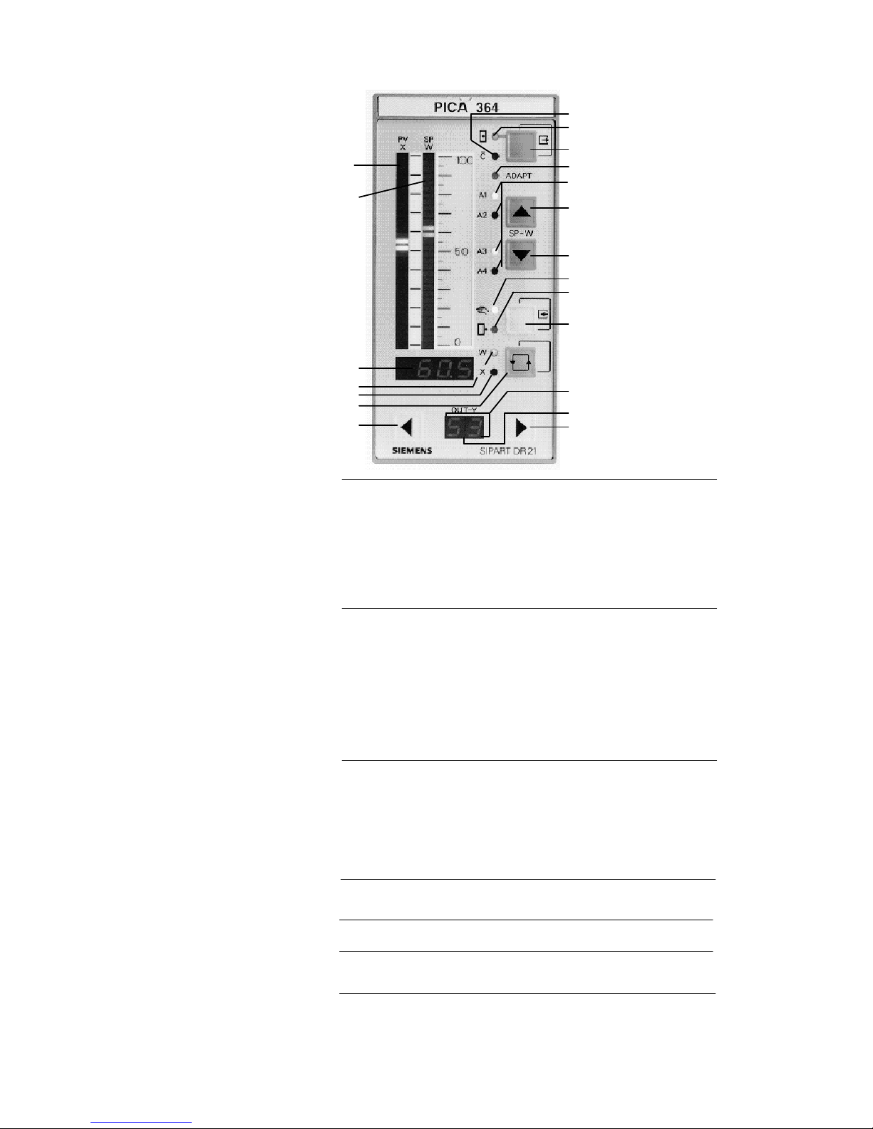
Controls and displays
1
2
3
4
5
6
7
8
9
10
11
13
12
14
15
16
17
18
19
20
1 Analog indication of actual value x
2 Analog indication of setpoint w
3 w/x digital display (other values can be displayed)
4 Signalling lamp w -- lights up if w is displayed
5 Signalling lamp x -- lights up if x is displayed
6 Selector pushbutton for w/x digital display,
acknowledgement pushbutton for flashing following return
of power or pushbutton for entering selection mode
7 Pushbutton for adjustment of manipulated variable --
closed (open)
8 Pushbutton for adjustment of manipulated variable --
open (closed)
9 y digital display
10 Signalling lamps of Δy digital outputs with S controller
11 Switchover pushbutton Manual/Automatic or “Enter” pushbutton
from selection mode of configuring mode
12 Signalling lamp for manual mode
13 Signalling lamp for y--external mode
Modification of setpoint 14 Pushbutton for falling setpoint
15 Pushbutton for rising setpoint
16 Selector pushbutton for internal/external setpoint or “”Exit’”
pushbutton from configuring and selection modes to process
operation mode
17 Signalling lamp for internal setpoint
18 Signalling lamp for computer switched off (with w
ext
)
Further messages 19 Signalling lamp for adaptation procedure running
20 Signalling lamp for “Limit triggered”
. Note Operation can be blocked using the digital signal bLb;
exception: switching over o w/x digital display.
Display of actual value
and setpoint
Modification of
manipulated variable
SIPART DR21
C73000-B7476-C143-08
5
Page 6
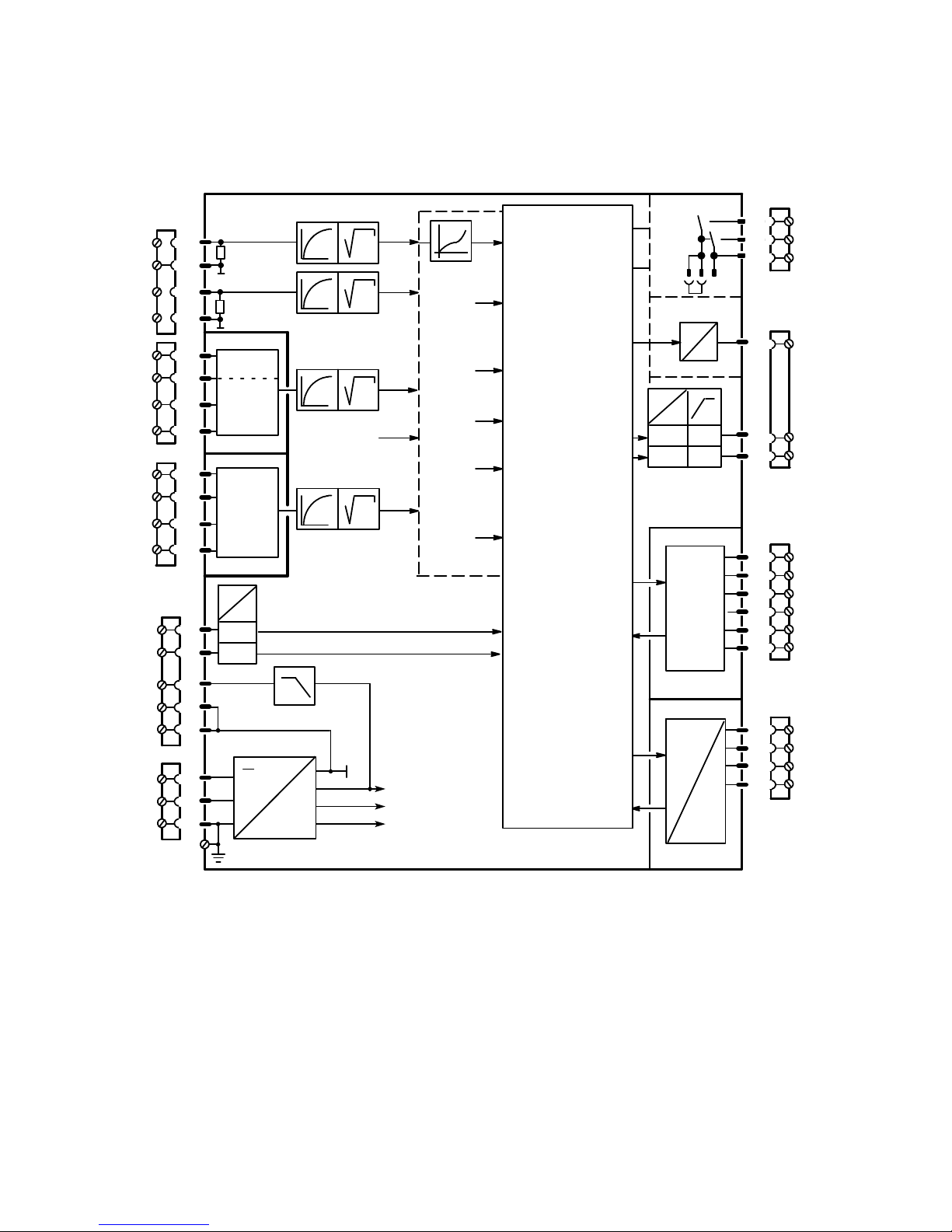
Block diagram
10
AI4A
S13
AI3A
t
S11
AI1A
S6
2
1
4
3
t
AI3
Slot 1
S7
Slot 2
I,U,R
I,U,R
AI4
Options
0%
Y
N
S18
DI1
DI2
24 V
5V
L+
GND
GND
N
L
M
+24 V
+5 V
U
REF
S14
t
S21
S57
DO7
DO8
24 V
5V
I
U
I
S56
15
14
13
8
7
S22
Z
S20
Y
R
S19
w
EA
/x3
S17
x2
S16
x1
S15
4DO 24V
2DI
2DO Rel
5DI
Slot 3
S84toS91
4/2
4/7
4/8
4/3
Slot 4
SES
5V
DO2
DO1
+Δy
--Δy
AO/Jy
I
Options
Txd
Rxd
S3
=
1/4
1/3
1/2
1/1
2/4
2/3
2/2
2/1
5
6
12
11
9
PE
3/6
3/5
3/4
3/3
3/2
3/1
∽
AI1
--
+
AI2
UNI
S8 to S10
t
S12
AI2A
S4
S5
249
249
--
+
Basic
settings
S1 to S3
Analog inputs
S4 to S21
Configuration of slot 3
S22
Digital inputs
S23toS41
Setpoint tracking
S42toS45
Control algorithm
S46toS48
Y switchover
S49toS53
Y indicator
S54toS55
Analog output
S56
Switching output
S57
Digital outputs
S58toS75
Limit monitors
S76toS80
x/w indicator
S81
Restart
conditions
S82toS83
Serial interface
S84toS91
L
SIPART DR21
C73000-B7476-C143-08
6
Page 7

Manual Contents
SIPART DR21
C73000-B7476-C143-08
7
Contents
page
1 General Part -- Fundamental control technology terms 9....................
2 Technical Description 17...................................................
2.1 Safety notes and scope of delivery 17..................................................
2.2 Range of Application 18..............................................................
2.3 Features 19........................................................................
2.4 Design 24..........................................................................
2.5 Function principle 26................................................................
2.5.1 Standard controller 26.................................................................
2.5.2 Option module 28....................................................................
2.6 Technical Data 34...................................................................
2.6.1 General data 34......................................................................
2.6.2 Standard controller 36.................................................................
2.6.3 Option module 40....................................................................
3 Functional description of the structure switches 47..........................
3.1 General 47.........................................................................
3.2 Analog input signal processing (S3 to S21) 47..........................................
3.3 Digital input signal processing (S23 to S41) 50..........................................
3.4 Controller types (S1, S42 to S45) 55...................................................
3.4.1 General, recurrent functions 55.........................................................
3.4.2 Fixed setpoint controller with 2 independent setpoints (S1 = 0) 59............................
3.4.3 Slave controller, synchronized controller, SPC-controller 62.................................
3.4.4 DDC-Fixed setpoint controller (S1 = 2) 68................................................
3.4.5 Controlled ratio controller (S1 = 3) 75....................................................
3.4.6 Control unit/process display (S1 = 4) 80..................................................
3.4.7 Fixed setpoint controller with one setpoint (control system coupling) 89.......................
3.4.8 Slave controller without Int/Ext -switching (control system coupling) 90........................
3.5 Control algorithm 91.................................................................
3.6 Controller output structures (S2, S49 to S55) 94.........................................
3.7 Analog output signal processing (S56) 110...............................................
3.8 Digital output signal processing (S57 to S75) 111.........................................
3.9 Adaptation (S48) 113.................................................................
3.10 Other functions of the standard controller 115............................................
3.10.1 Adaptive filter 115.....................................................................
3.10.2 Response threshold AH 116............................................................
3.10.3 Limit value alarm (S76 to S80) 117.......................................................
3.10.4 Linearizer (S21, oFPA) 118.............................................................
3.10.5 Restart conditions (S82, S83) 120........................................................
3.10.6 Serial interface and PROFIBUS-DP (S84 to S91) 120.......................................
4 Installation 121.............................................................
4.1 Mechanical Installation 121............................................................
4.1.1 Work prior to installation 121............................................................
4.1.2 Installing the controller 124..............................................................
4.1.3 Installation of the options modules 125....................................................
4.2 Electrical Connection 126.............................................................
4.2.1 Warnings and block diagram 126.........................................................
4.2.2 Connection standard controller 130.......................................................
4.2.3 Connection of the options modules 133...................................................
4.2.3.1 Modules for analog measuring inputs 133.................................................
4.2.3.2 Connection examples for analog measuring inputs with the module 6DR2800-8J 137.............
4.2.3.3 Modules for expanding the digital inputs and digital outputs 142...............................
4.2.4 Connection of the interface module 6DR2803-8C 144.......................................
4.2.4.1 RS 232 point-to-point (END/END) 144....................................................
4.2.4.2 RS 485 bus 145.......................................................................
4.2.4.3 PROFIBUS-DP, 6DR2803-8P 146........................................................
Page 8

ManualContents
8
SIPART DR21
C73000-B7476-C143-08
5 Operation 149..............................................................
5.1 General 149.........................................................................
5.2 Process operation mode 150..........................................................
5.3 Selection mode 152..................................................................
5.4 Configuration modes 154..............................................................
5.4.1 General, Online and Offline modes 154...................................................
5.4.2 Configuration mode online-parameters onPA 155..........................................
5.4.3 Configuration mode adaptation AdAP 156................................................
5.4.4 Configuration level offline parameters oFPA 163...........................................
5.4.5 Configuration mode structure switch StrS 165.............................................
5.4.6 Set UNI-module CAE3 173............................................................
5.4.6.1 Measuring range for mV (S8 = 0) 175.....................................................
5.4.6.2 Measuring range for U, I (S8 = 0) 175.....................................................
5.4.6.3 Measuring range for thermocouple with internal reference point (S8 = 1) 175....................
5.4.6.4 Measuring range for thermocouple with external reference point (S8 = 2) 176....................
5.4.6.5 Measuring range for PT100 four-wire and three-wire connection (S8 = 3,4) 176..................
5.4.6.6 Measuring range for PT100 two-wire connection (S8 = 5) 177.................................
5.4.6.7 Measuring range for resistance potentiometer (S8 = 6, 7) 177.................................
5.4.7 APSt (All Preset) Reset to factory setting 178..............................................
5.5 CPU self-diagnostics 179..............................................................
6 Commissioning 181........................................................
6.1 Adapting the direction of control action to the controlled system 181.........................
6.2 Setting of actuating time in K-controllers (S2 = 0) 183......................................
6.3 Adaptation of the S-controller to the actuating drive 183....................................
6.4 Setting the filter and the response threshold 185..........................................
6.5 Automatic setting of control parameters by the adaptation method 186.......................
6.6 Manual setting of the c ontrol parameters without knowledge of the plant behavior 189..........
6.7 Manual setting of the control parameters after the transient function 191......................
7 Application examples for configuring the controller 193.......................
7.1 General 193.........................................................................
7.2 Working with different setpoints 195.....................................................
7.3 Configuration examples 199...........................................................
7.4 Configuring tool, forms 216............................................................
8 Maintenance 223...........................................................
8.1 General information and handling 223...................................................
8.2 Exchanging components 224..........................................................
8.3 LED-test and software version 226......................................................
8.4 Spare parts list 227...................................................................
8.5 Ordering data 228....................................................................
9 General explanation of abbreviations for SIPART DR 229......................
Index 235........................................................................
Page 9
1HL1Manual
SIPART DR21
C73000-B7476-C143-08
9
1 General Part -- Fundamental control technology terms
D Control loop
The function of a closed-loop control is to bring the output variable x of a controlled system
to a predefined value and to retain this value even under the influence of disturbance
variables z. The controlled variable x is compared with the command variable w. The
resulting system deviation xd = w -- x is processed in the controller to the manipulated
variable y which acts on the controlled system.
The controlled variable x is measured cyclically in a digital control.
w Command variable
x Controlled variable
xd System deviation
y Manipulated variable
z Disturbance variable
1 Controlled system
2 Control equipment
z1 z2 z3
1
2
y
x
xd
w
-
+
Figure 1-1 Function diagram of control loop
D Sensors and transmitters
The controlled variable can be any physical variable. Frequently controlled variables in process engineering are pressure, temperature, level and flow.
In most process engineering applications, the process variables are measured using sensors
and transmitters with a standardized signal output (0 to 20 mA or 4 to 20 mA). The standardized signal can be connected to several process process devices (loop between e.g. recorder/indicator/controller). Temperature sensors such as resistance thermometers or thermocouples, as well as resistance transmitters, can be connected directly to the controller
using appropriate input cards (options).
D Final control elements and actuators
In process engineering applications, the manipulated variale y primarily acts on the controlled system via a valve, a butterfly valve or another mechanical means of adjustment.
Three types of drive are possible for actuating such final control elements:
- Pneumatic actuators with compressed air as the auxiliary energy and electropneumatic
signal converters or electropneumatic positioners. These have a proportional action and
are driven by continuous controllers.
- Electric actuators, consisting of an electric motor and gear unit. These have an integral
action and are driven by three-position step controllers. Electric actuators are also possible with an integrated (series-connected) positioner and then have a proportional action
and can be driven by continuous controllers.
Page 10

1 General Part -- Fundamental control technology terms Manual
10
SIPART DR21
C73000-B7476-C143-08
- Hydraulic actuators with electric oil pump and electrohydraulic positioner. These have a
proportional action and are also driven by continuous controllers.
These types of actuators can be used to implement continuous controls.
- Temperature control loops with diret electric or gas heating and/or cooling systems are
driven by two-postion controllers (on/off controllers). The two-position controllers with the
heating or cooling medium via relays, external contactors or thyristor controllers. The manipulated variable y is the on/off ratio. These are referred to as discontinuous controls.
D Controllers and control response
The controlled variable x is compared with the command variable w in the input circuit of the
controller, and the system deviation xd is determined. This is processed with or without a
time response into the output signal. The output signal of the amplifier can directly represent
the manipulated variable y if e.g. proportional-action final control elements are to be driven
by it.
In the case of electric actuators, the manipulated variable is produced by the actuator. The
required positioning inrements are derived from the controller ouptut as a pulse-width-modulated signal by conversion.
Depending on the design of this circuit, the controller has a proportional action (P), a proportional-plus-derivative action (PD), a proportional-plus-integral action (PI) or a proportionalplus-integral-plus-derivative action (PID).
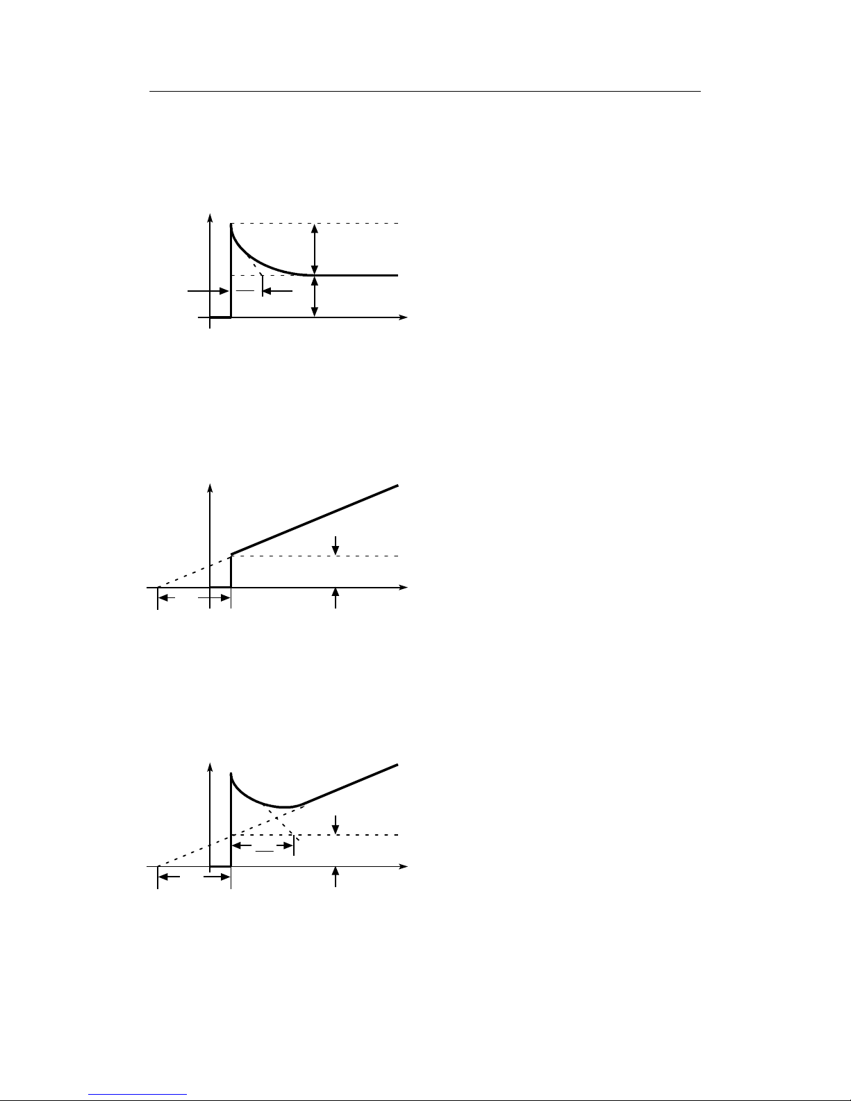
D Step function
If a step function is applied to the controller input, a step-forced response results at the output of the controller in accordance with its time response.
xd
t
Figure 1-2 Step function
D P controller, step-forced response
Characteristic of the P controller are the proportional gain Kp and the working point y
o
.The
working point is defined as the value of the output signal at which the system deviation is
zero. If disturbance variables are present, a steady-state deviation may result depending on
y
o
.
y
t
Kp · xd
y
O
Figure 1-3 Step-forced response of P controller
Page 11
1 General Part -- Fundamental control technology termsManual
SIPART DR21
C73000-B7476-C143-08
11
D PD controller, step-forced response
In the case of the PD controller, the decaying D component is superimposed on the P component. The D component depends on the derivative action gain Vv and the derivative action
time Tv.
y
t
Tv
Vv
Kp · Vv · xd
Kp · xd
yO=0
Figure 1-4 Step-forced response of PD controller
D PI controller, step-forced response
In contrast to the P controller, a steady-state deviation is prevented in the PI controller by
the integral component.
A characteristic of the integral component is the integral action time Tn.
y
t
Kp · xd
Tn
Figure 1-5 Step-forced response of PI controller
D PID controller, step-forced response
The PID controller results in improvement of the dynamic control quality as a result of the
additional application of a D component.
Refer to the PD and PI controllers.
y
t
Kp · xd
Tn
Tv
Vv
Figure 1-6 Step-forced response of PID controller
Page 12
1 General Part -- Fundamental control technology terms Manual
12
SIPART DR21
C73000-B7476-C143-08
D Controller output signal
The controller ouptut signal must be adapted to the final control element. The following must
be used according to the type of drive/final control element:
Type of drive/actuator
Controller output signal
Electric actuators Three-position step controllers
Pneumatic and hydraulic actuators Continuous controllers
Direct heaters/coolers Two-position controllers
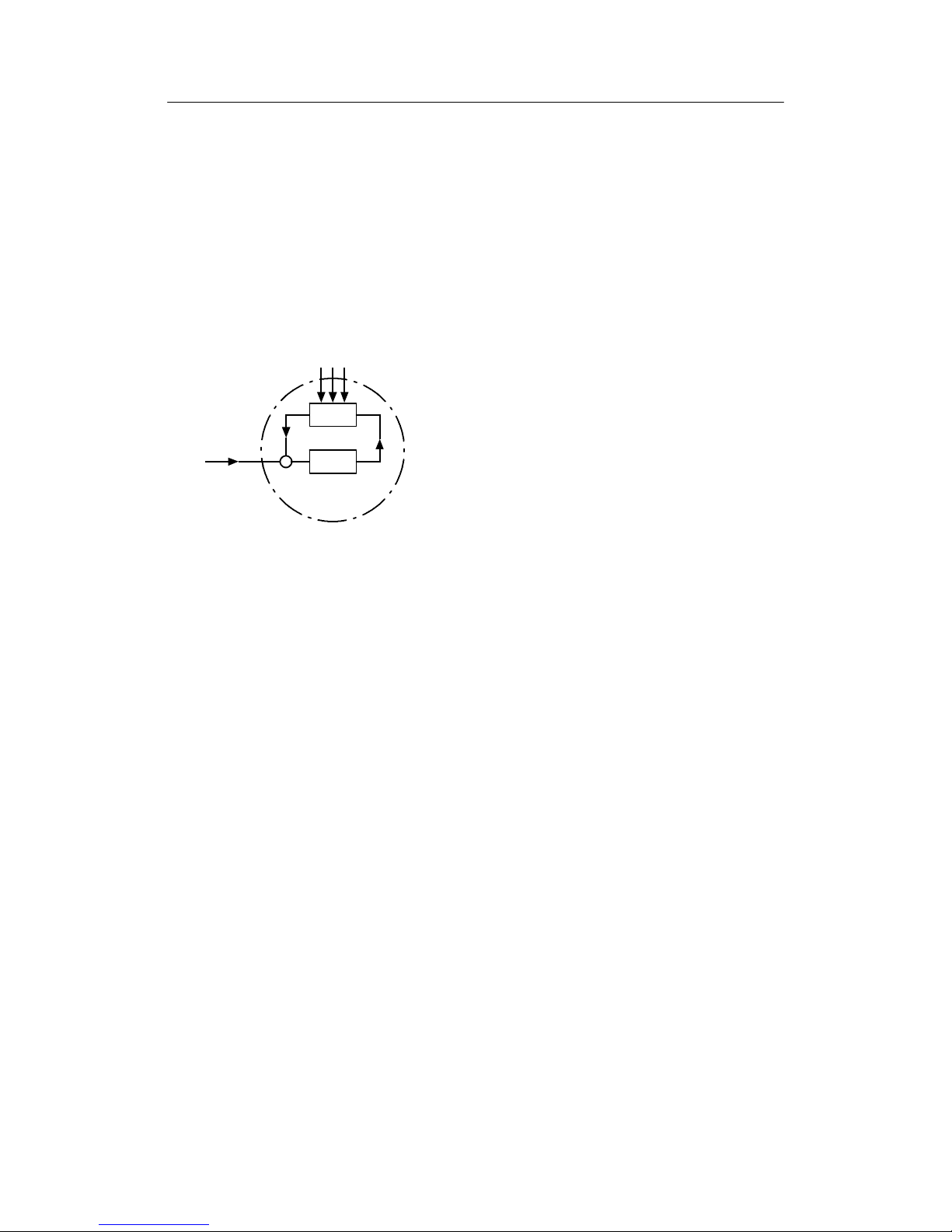
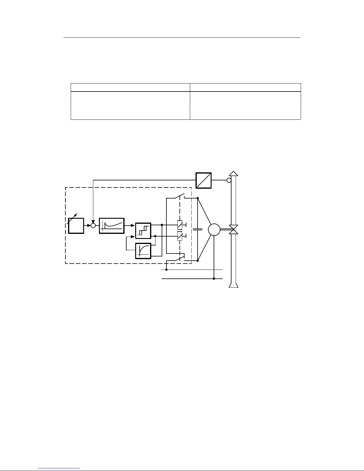
D Three-position step controller with internal feedback
The three-position step controller switches the electric motor of the actuator to clockwise,
stop or counterclockwise by means of relays or semiconductor switches. The rate of adjustment of the actuator can be influenced using different switch-on/pause ratios.
w Command variable
x Controlled variable
xd System deviation
y Manipulated variable
1 Transmitter
2 Stepoint adjuster
3 Three-position switch
4 Feedback with time
response
5 Control amplifier
6 Actuator
2
M
w
xd
5
3
4
L1
N
1
x
6
y
0 to 20mA
(4 to 20mA)
Figure 1-7 Function diagram of three-position step controller
The output response to the three-position amplifier in conjunction with the integral-action
actuator permits a “continuous” manipulated variable taking into account the response
threshold.
Page 13
1 General Part -- Fundamental control technology termsManual
SIPART DR21
C73000-B7476-C143-08
13
Kp Proportional gain
Tn Integral action time
xd System deviation
Δy Manipulated variable of controller
y Manipulated variable of motor
Tn
Kp · xd
y
Δy
t
t
Figure 1-8 Transient function and parameters of the three-position step controller
D Continuous controller
The controller output 0 to 20 mA or 4 to 20 mA acts on the final control element via an
electropneumatic signal converter or an electropneumatic positioner.
2
w
xd
3
1
x
y
-
4
0to20mA
(4 to 20 mA)
0.2 to 1 bar
w Command variable
x Controlled variable
xd System deviation
y Manipulated variable
1 Transmitter
2 Stepoint adjuster
3 Control amplifier
4 Electropneumatic signal
converter
5 Pneumatic actuator
Figure 1-9 Function diagram of continuous controller
This type of controller is preferentially used in the chemical industry.
Page 14
1 General Part -- Fundamental control technology terms Manual
14
SIPART DR21
C73000-B7476-C143-08
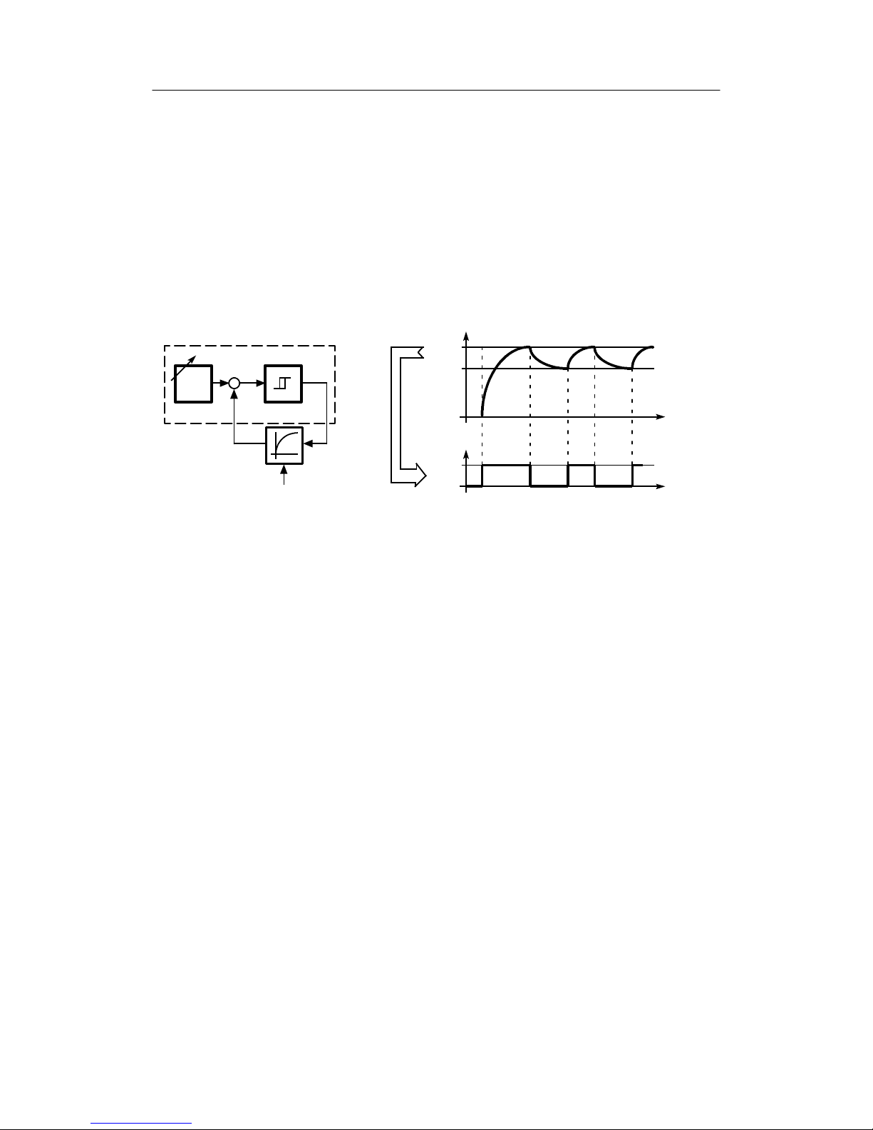
D Two-position controller
The two-position controller (or three-position controller for heating/cooling) is used to activate
relays, contactors or thyristor switches for electric heating or cooling.
- Two-position controller without feedback
In the simplest version without feedback, two-position controllers operate an on/off
switch. The controllers output is switched if the controlled variable violates the upper or
lower limits of the switching hysteresis (x1 and x2). The controlled variable x is subject to
permanent oscillation whose frequency and amplitude depend on the delay time of the
system and the switching hysteresis of the controller.
1 Controller
2 Controlled system
3 Setpoint adjuster
3
w
xd
1
y
2
x
z
t
t
x
y
x1
x2
w Command variable
x Controlled variable
y Manipulated variable ON/OFF
z Disturbance variable
On
Off
Figure 1-10 a) Function diagram b) Switching ouptupt and response of controlled variable
Page 15
1 General Part -- Fundamental control technology termsManual
SIPART DR21
C73000-B7476-C143-08
15
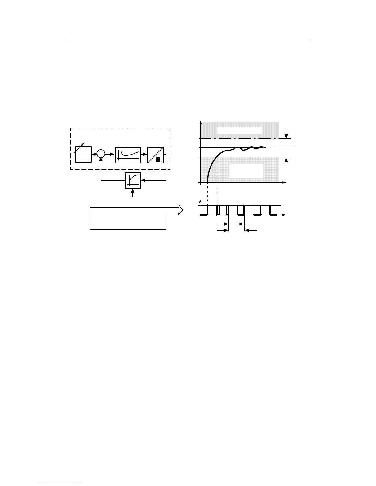
- Two-position controller with feedback
In modern two-position controllers with feedack -- such as the SIPAR T DR21 -- the
switching response is determined by the period, the system deviation and the parameters. The period T is set as a fixed value in the controller. The system deviation xd in
conjunctionw ith the parameters Kp/Tn/Tv determines the duty factor (ON/OFF ratio)
within the period. Thus the switching response of the controller is not only triggered by
changes in the controlled variable; appropriate selection of the parameters results in a
largely constant controlled variable x.
1 Control amplifier
2 Controlled system
3 Setpoint adjuster
4 Pulse/pause converter
3
w
xd
1
y
2
x
z
t
t
y
On
Off
-
-
+
-
4
*)
T
w
Duty factor 0 %
Duty factor
100 %
2 ¢ 100 %
Kp
-PeriodT
- System deviation xd
- Parameters Kp, Tn, Tv
w Command variable
x Controlled variable
y Manipulated variable
Z Disturbance variable
TPeriod
*) Duty factor (in % if period)
Figure 1-11 a) Function diagram b) Switching output and resosne of controlled variable
Adjustment of the period (separately for heating/cooling) permits the controller to be
adapted to the special type of heater or the cooling unit. A compromise has to be made
beween the control quality and the degree of wear.
Short period: Improved control quality, but increased wear on contact/heating valve.
Prime use with electric heaters.
Long period: Low wear on contact/heating valve, but poorer control quality. Prime
application with gas heaters or coolers.
Page 16

1 General Part -- Fundamental control technology terms Manual
16
SIPART DR21
C73000-B7476-C143-08
Page 17

2 Technical Description
2.1 Safety notes and scope of delivery
Manual
SIPART DR21
C73000-B7476-C143-08
17
2 Technical Description
2.1 Safety notes and scope of delivery
!
WARNING
When operating electrical equipment, certain parts of this equipment automatically carry dangerous voltages. Failure to observe these instructions could
therefore lead to serious injury or material damage. Only properly trained and
qualified personnel are allowed to work on this equipment. This personnelmust
be fully conversant with all the warnings and commissioning measures as described in this user’s guide.
The perfect and safe operation of this equipment is conditional upon proper
transport, proper storage, installation and assembly as well as on careful operation and commissioning.
D Scope of delivery
When the controller is delivered the box also contains:
1 Controller as ordered
1 three-pin plug at 115/230 V AC or special plug at 24 V UC
2 Clamps, pluggable
2 Adhesive labels ”Power supply 115 V” (for 115/230 V-version).
1 CD ROM with documentation
D Standard controllers
The following variants of the SIPART DR21 are available:
Order number:
Output stage Power Supply
6DR2100-4 K/S-output 24 V UC
6DR2100-5 K/S-output 1 15/230 V AC, switchable
D Options modules (signal converters)
Signal converters have separate ordering- and delivery items.
For handling reasons standard controllers and signal converters which were ordered at the
same time may be delivered by separate mail.
D Documentation
This user’s guide is available in the following languages:
English C73000-B7476-C143
German C73000-B7400-C143
Page 18

2 Technical Description
2.2 Range of Application
Manual
18
SIPART DR21
C73000-B7476-C143-08
D Subject to modifications
The user’s guide has been compiled with great care. However, it may be necessary, within
the scope of product care, to make changes to the product and its operation without prior
notice which are not contained in this user’s guide. We are not liable for any costs ensuing
for this reason.
2.2 Range of Application
D Application
The SIPART DR21 process controller is a digital instrument of the mid to upper performance
class. It is used in control systems in process engineering for instance in the chemical and
petrochemical industries, control- and power station engineering and in other fields of industry such as the food- and drink and tobacco industries.
The controller’ s great flexibility makes it suitable for use in simple or intermeshed control circuits. The wide setting range of the control parameters allow the SIPART DR21 to be used
in process engineering both for fast (e.g. flow) and slow controlled systems (e.g. temperature). The controller determines the optimum control parameters independently on request
without the user being expected to have any prior knowledge of how the control loop may
respond. The applied adaptation procedure is suitable for systems with compensation and
aperiodic transient behavior; Even greater dead times are taken into account. (Systems without compensation cannot be adapted by this method.)
D Controlling tasks
The input structure of the SIPART DR21 controller can be changed by configuring in such a
way that the following controlling tasks can be solved.
- Fixed value controls, even with disturbance variables applied at the input
- Three-component controls
- Control circuits with up to two internal setpoints
- Follow-up-/synchronization controls
- Disturbance variables applied at the output
- Computer-controlled circuits in SPC- or DDC-operation
- Ratio controls with fixed or manipulated variables
SIPART DR21 can also be configured as a control unit, manual control unit, process display
or resolver transmitter.
The SIPART DR21 controller can be used as a continuous controller with output 0/4 to
20 mA, as a stepper controller with a built-in relay for controlling motorized drives or as a
two-position controller for heating/cooling systems.
Overlaid control functions or status- and alarm messages are possible through digital inputsand outputs.
Page 19

2 Technical Description
2.3 Features
Manual
SIPART DR21
C73000-B7476-C143-08
19
2.3 Features
D General
Up to four signal converters can be added to the already generously and extensively equipped, fully
functional standard controller to expand the range of application by plugging them into the slots at
the back of the closed device.
SIPART DR21 offers the following features:
D Analog inputs
Two analog inputs for current 0/4 to 20 mA, without potential isolation
The SIPART DR21 controller can be expanded to a total of 4 analog inputs with signal
converters.
The following signal converters are available:
Use as (on) Possible signal generators
UNImodule
AI3 (slot 1) TC/RTD/R/mV, with adapter plug also mA or V, electri-
cally isolated, permissible common mode voltage 50 V .
U/Imodule
AI3 (slot 1)
AI4 (slot 2)
0/4to20mA,0/2to10V,0/0.2Vto1V
Electronic potential isolation, permissible common
mode voltage 10 V.
Rmodule
AI3 (slot 1)
AI4 (slot 2)
Resistance potentiometer
In addition, the modules from the previous program (thermocouple/mV and Pt100) can be
used (see SIPART DR20 user’s guide for wiring).
D Output structure
The SIPART DR21 controller has a y-analog output (manipulated variable) with a current
signal of 0/4 to 20 mA and a switching output with two built-in relays which are interlocked.
The relay lock can be released for a universal digital output. The relays are designed for AC
250 V, a spark quenching combination for wiring with contactors is provided.
The SIPART DR21 can be configured to operate as a continuous controller, a stepper controller for motorized drives or as a two-position controller.
When used as S-controllers, the analog output can be used for outputting x, w or xd for
example.
Page 20

2 Technical Description
2.3 Features
Manual
20
SIPART DR21
C73000-B7476-C143-08
!
WARNING
The relays are designed for a maximum switching voltage of AC 250 V/8 A in
overvoltage class III and degree of contamination 2 according to DIN EN
61010 Part 1.
The same applies for the air- and creep lines on the circuit board.
Resonance increases up to three times the rated operating voltage may occur when phase shift motors are controlled. These voltages are available at
the open relay contact. Therefore such motors may only be controlled under
observance of the technical data and the pertinent safety conditions via isolated switching elements.
D Voltage output
A voltage output L+ for feeding two-wire-transmitters or contacts for digital inputs.
D Slots for options
Four rear slots can be used for functional expansions. The options modules are slot coded
so that wrong installation is largely ruled out.
Slot assignment, see figure 2-2 Rear view, page 25.
D Power supply unit
The power supply unit is designed for the following voltages depending on the standard controller:
- 230 V/115 V AC, switchable by plug-in jumpers in the instrument.
-24VUC
Page 21

2 Technical Description
2.3 Features
Manual
SIPART DR21
C73000-B7476-C143-08
21
D Digital inputs
Two digital inputs, potential-bound
It can be upgraded to four or seven potential-bound digital inputs with signal converters.
The digital inputs can be assigned to the following controller-internal switching signals.
bLb Blocking operation
Blocking the entire instrument operation and configuring.
Exception: Switching the w/x-digital display
bLS Blocking structuring
With this signal the controller only allows switching to the
online-parameterization levels outside process operation. In this way the
parameters for adapting the instrument to the process and the necessary
settings for adaptation can be selected. Structuring is blocked.
bLPS Blocking parameterization and structuring
The entire configuring of the instrument is blocked, this means the
parameterization as well. Only the normal process operation according to the
preselected controller type is permitted.
CB Computer-standby
Depending on the controller type, this digital signal together with the
Internal/External key causes either switching in the setpoint range. In
DDC-controllers, DDC-operation begins.
He Manual external
This signal blocks the output of the controller and enables direct manual
adjustment of the manipulated variable on the front control panel.
N Tracking
With this signal the output of the K-controller and the three-position-step
controller with external position feedback is tracked to the tracking signal y
N
.
Si Safety operation
The output of the K-controller or the three-position-stepper controller with
external position feedback accepts the parameterized safety value. In
three-position-stepper controllers with internal position feedback, the
manipulated variable runs defined to 0 or 100 %.
P P-operation
Switching from PI (PID) to P (PD)-controller (i.e. switch off the I-part)
This function simplifies automatic start-up of control circuits.
tS
Switching off the setpoint ramp time
tSH Hold on setpoint change (setpoint ramp)
+yBL / --yBL Direction-dependent blocking of the manipulated variable
Direction-dependent limiting of the manipulated variable by external signals,
e.g. from the limit switches of the actuating drives. This limiting is effective in
every operating mode.
Page 22

2 Technical Description
2.3 Features
Manual
22
SIPART DR21
C73000-B7476-C143-08
D Digital outputs
Two digital outputs, active, potential-bound.
It can be upgraded to four or six digital outputs with signal converters.
The digital outputs are loadable up to 30 mA per output for direct tripping of relays.
The digital outputs can also be used for the variable output, the relay outputs are then free
for any digital signal output.
The following controller-internal switching signals can be assigned to the digital outputs or
relays.
RB
Computer standby
Message that the controller can be switched to the external setpoint by the
CB-signal.
RC
Computer operation
Message that the controller is presently in computer operation or that it has
been switched over to the external setpoint by the CB-signal.
H Manual mode
Message that the controller has been switched over to manual mode with the
Manual/Automatic key.
Nw Tracking operation active
Message that the controller is in tracking operation.
A1 bis A4 Alarm output Alarm 1 to Alarm 4
MUF group alarm transmitter fault
The instruments’s analog input signals can be monitored for exceeding of the
measuring-range. This signal gives a group alarm if an error is detected.
Δw Output of switching signals for setpoint adjustment
This function is only active when the controller is structured as a control unit
(S1=4).
Δy Output of the incremental y-adjustment
Assignment is only possible on DO1, 2, 7 or 8 (S57).
The following signal converters are available for extending the digital inputs and outputs:
Use on Description
4 x DO/2 x DI Slot 3 4 binary outputs 24 V
2 binary inputs 24 V
5xDI Slot 3 5 binary inputs 24 V
2xrelays Slot 3 2 relay outputs 35 V
D Serial interface
An interface can be retrofitted with signal converters for RS 232/RS 485 or PROFIBUS DP.
Page 23

2 Technical Description
2.3 Features
Manual
SIPART DR21
C73000-B7476-C143-08
23
D Others
Further functions are also possible. Examples:
Meaning see chapter
Adaptationprocedure
Automatic determining of the controller parameters by
means of a robust adaptation method which also considerably simplifies commissioning of even critical controlled systems.
Configuring level
AdAP; 3.9 (page
113) and 5.4.3 (page
156)
adaptive filter forxdFilter which dampens amplitude-dependent interference, the
value of the dampening is adapted automatically.
onPA-Parameter tF
3.10.1 (pg. 115) and
5.4.2 (page 155)
Setpoint ramp Prevents the setpoint or nominal ratio being changed too
fast. The desired adjustment speed can be set. The time for
the change is set from 0 to 100 % here. The setpoint ramp is
not active at x-tracking and digital signal tS
.
oFPA-Parameter tS;
3.4.1 (pg. 55) and
5.4.4 (pg. 163)
Filter for all inputs A 1st order filter can be connected to every analog input. onPA-Parameters t1
to t4; 3.2 (pg. 47)
and 5.4.2 (pg. 155)
Root extractor for
all controller inputs
A root extractor can be connected before every analog input. Structure switches
S11 to S14; 3.2 (pg.
47) and 5.4.5 (pg.
165)
Linearizer for an
input variable
A linearizer with 13 (equidistant) support points and parabolic approximation can be assigned to one of the analog
inputs AI1 to AI4 or to the controlled variable x1.
Structure switch
S21; 3.10.4 (pg.
118) and 5.4.5 (pg.
165)
Initialization of the
display x/w
The controlled variable x and the command variable w can
be displayed in physical values.
oFPA-Parameter dA,
dE; 3.4.1 (pg. 55)
and 5.4.4 (pg. 163)
Limits for the setpoint w
The setpoint can be limited anywhere within the selected
measuring range.
oFPA-Parameter
SA, SE;
3.4.1 (pg. 55) and
5.4.4 (pg. 163)
Limits of the
manipulated
variable y
The manipulated variable y can be limited within the setting
range –10% and +110 %.
(Not in S-controllers with internal feedback)
onPA-Parameter YA,
YE; 3.5 (pg. 91) and
5.4.2 (pg. 155)
x-Tracking The setpoint w is tracked to the controlled variable x in
manual-, tracking- and DDC-operation as well as at the
safety setpoint.
Structure switch
S43; 3.4.1 (pg. 55)
and 5.4.5 (pg. 165)
Limit value alarms Any controller-internal variables or inputs can be monitored
for limit values. The output is by way of alarms A1 to A4.
Structure switches
S76 and S77; 3.10.3
(pg. 117) and 5.4.5
(pg 165)
Transmitter
monitoring
All or specific analog inputs can be monitored for dropping
below- or- exceeding the range. In the event of a fault, the
four-digit digital display outputs a message selectively for
every input. A system fault can be output via the digital output MUF.
Structure switches
S4 to S7, S66; 3.2
(pg. 47) and 5.4.5
(pg. 165)
Adaptation of the
direction of action
SIPART DR21 operates with normal direction in the factory
setting. The direction of the controller can be changed for
reversing systems.
Structure switch
S46; 3.5 (pg 91) and
5.4.5 (pg. 165)
Restart conditions After mains recovery the controller starts automatically with
the structured operating modes, setpoints and manipulated
variables.
Structure switch
S82; 3.10.5 (pg.120)
and 5.4.5 (pg. 165)
Page 24

2 Technical Description
2.4 Design
Manual
24
SIPART DR21
C73000-B7476-C143-08
2.4 Design
D Standard controller
The process controller has a modular structure and is therefore maintenance friendly and
easy to convert- and retrofit.
The standard controller consists of
- the front module with the control- and display elements
- the backplane module with the power supply unit
- the plastic housing with four slots for optional modules
D Front module
The front module accommodates the control- and display elements, the CPU (Central Processing Unit) and the connectors for the backplane- and options modules.
It is operated by a membrane keyboard with IP64 degree of protection. The front design is
based directly on the SIPART DR 20/22/24-controller-family with color coded assignment of
the display- and control elements.
For better monitoring of the process, SIPART DR21 has user-friendly analog displays for the
setpoint- and actual value display, a four-digit digital display which can be set for setpoint,
actual value and alarms (depending on the controller setting), a two-digit digital display for
the manipulated variable y, numerous control keys and indicator diodes for various status
signals.
The tag plate and the scales for the analog displays are replaceable.
D Backplane module with power supply unit
The following signal connections are accessible through the backplane.
- 2 analog inputs AI1, AI2, potential-bound to GND, 0/4 to 20 mA
- 1 analog output AO, potential-bound to GND, 0/4 to 20 mA
- 2 digital outputs + Δ y, - Δ y, potential-free via relay contacts
- 2 digital inputs DI1, DI2, for 24V-logic, function can be set
- 2 digital outputs DO1, DO2, for 24V- logic, function and direction can be set
- 1 Voltage output L+ to the transmitter supply
The power supply is located in a die-cast housing on the backplane module. The heat loss is
transferred to the back of the controller by cooling fins.
A DIN rail can be mounted for connecting a powerful coupling relay module.
The power supply unit is high powered and offers a total 200 mA current for:
- supplying the analog output (0/4 to 20 mA)
- Active digital outputs (up to 6 digital outputs)
- L+-output for supplying two-wire-transmitters
- supplying the interface module
Page 25
2 Technical Description
2.4 Design
Manual
SIPART DR21
C73000-B7476-C143-08
25
D Connection technique
The power supply is connected
- for 230 V/115 V AC by a three-pin plug
- for 24 V UC by a special two-pin plug.
On the standard controller the field lines (signal cables) are connected to three functionally
combined plug-in screw-type terminals.
The options modules for analog inputs and digital inputs- and outputs have their own terminals which are also designed as plug-in screw-type terminals.
The interface module is connected by its own plug.
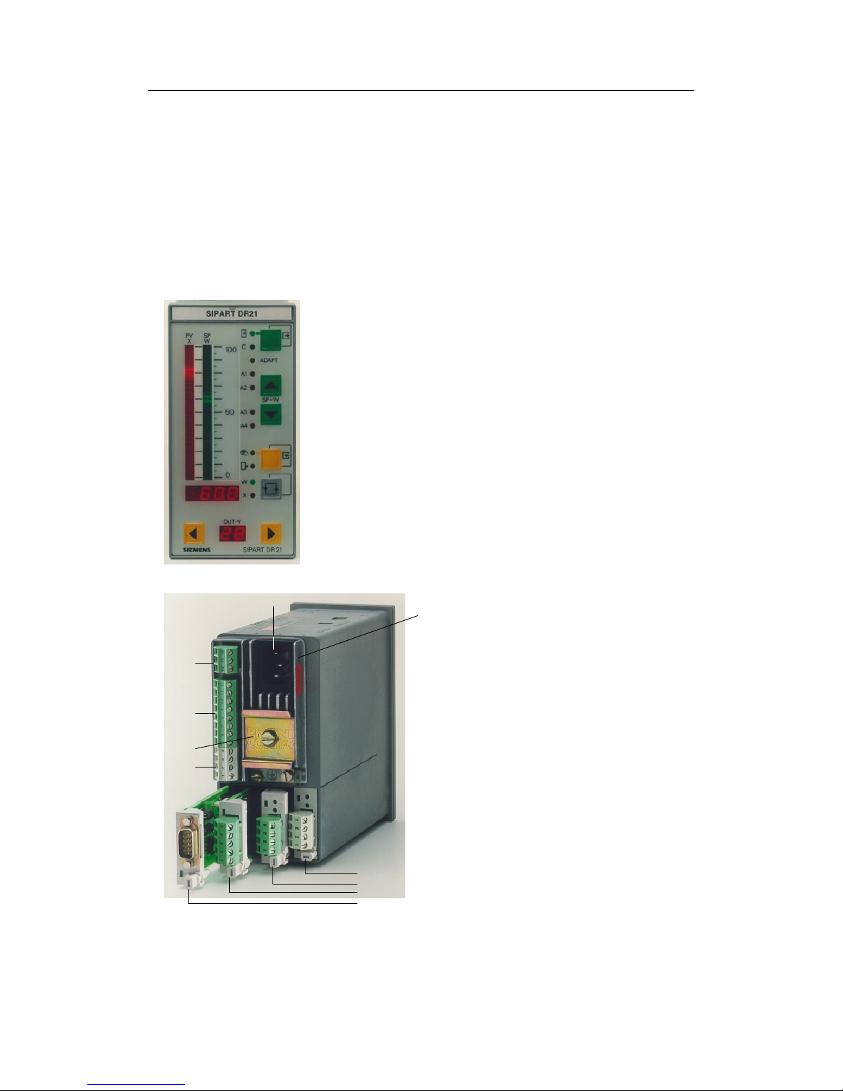
Figure 2-1 Front view
1 Mains plug
2 Power supply unit
3 Slot1 AI3(I/U,R,P,T)
4 Slot2 AI4(I/U,R,P,T)
5 Slot 3 4DO,24 V or
2DO relay or
5DI
6 Slot 4 SES/PROFIBUS-DP
7DINrail
(scope of delivery of the relay module)
8 Terminal block 1
AI1toAI2(I)
9 Terminal block 2
AO1
DI1toDI2
DO1toDO2 24V
L+; M
10 Terminal block 3
Digital outputs ±
Δy
3
4
5
6
2
1
10
9
7
8
Figure 2-2 Rear view
Page 26

2 Technical Description
2.5 Function principle
Manual
26
SIPART DR21
C73000-B7476-C143-08
2.5 Function principle
2.5.1 Standard controller
D General
The SIPART DR21 controller operates on the basis of a modern, highly-integrated microcontroller in C-MOS-technology. A large number of functions for controlling processing plants
are stored in the instrument’s ROM. The user can adapt the controller to the task himself by
configuring it.
D Analog inputs AI1 and AI2.
The analog inputs of the SIPART DR21 are designed for 0/4 to 20 mA input signals. The inputs have an input load resistance of 248 Ω and are potential-bound. The start value 0 mA
or 4 mA is determined by the structure switches S4 and S5.
D Outputs for the manipulated variable Y
The standard controller has the following outputs
K-output: switchable between 0 or 4 to 20 mA, potential-bound (S56)
S-output: two relays, NOC, interlocked in factory setting, built-in spark quenching de-
signed for wiring with medium contactors. Other functions can be assigned
to the relay outputs by configuration (structure switches S57 to S68), e.g.
manipulated variable output ±Δy in S-controllers.
D Digital outputs DO1 and DO2
The digital outputs are short-circuit-proof and can drive commercially available relays or the
interface relays 6DR2804-8A/8B directly. Different functions can be assigned to the digital
outputs by configuration (structure switches S57 to S68).
D Digital inputs DI1 and DI2
The inputs are designed in 24-V-logic and are potential-bound. The function is assigned to
the input by configuration of the controller (structure switches S23 to S33).
D CPU
The microcontroller used has integrated AD- and DA-converters and watchdog-circuits for
cycle monitoring. The processor operates with a 64k EPROM (on a socket and therefore
replaceable) and a 1k RAM.
The SIPART DR21 program runs with a fixed cycle time of 100 ms. A process image is generated at the start of every routine. The analog- and digital inputs, the operation of the front
keyboard and the process variables received by the serial interface are acquired or
accepted. All calculations are made according to the stored functions with these input signals. Then output to the display elements, the analog outputs and the digital outputs and
Page 27

2 Technical Description
2.5 Function principle
Manual
SIPART DR21
C73000-B7476-C143-08
27
storage of the calculated variables for transmission mode of the serial interface take place.
In S-controllers, the program run is interrupted every 5 ms to be able to switch off the S-outputs for better resolution. The interface communication also runs in interrupt mode.
D Power supply unit
A cast, overload-protected mains transformer for 115 V or 230 V AC built into a heat sink or
a primary clocked plug-in type power supply unit for 24 V UC built into a heat sink generates
the secondary internal supply voltages +24 V, +5 V and U
ref
from the power supply. The
metal body rests on protective conductors (protection class
I).
The power supply and internal supply voltages are isolated from each other by safe
separation.
The internal supply voltages are function low voltages.
Since no other voltages are generated in the instrument, these statements apply to all field
signal lines with the exception of relay connection lines (used standards see chapter 2.6
Technical data, page 34).
D Configuring
The controller has a large number of prepared functions for controlling processing plants.
The user programs the instrument himself by selecting the desired functions or setting parameters by setting structure switches. The total functioning of the instrument is given by the
combination of the individual structure switches or parameter settings. No programming
knowledge is necessary (see Operation, chapter 5, page 149).
All settings are made without exception on the front operating panel of the SIPART DR21 or
the serial interface.
The job-specific program written in this way is saved in the non-volatile user program memory.
The instrument is configured as a fixed value controller in the factory setting. This setting
can be restored with the ”APSt”-function at any time.
The following parameterization- and structuring modes are available for configuring the
SIPART DR21 controller.
onPA The transmission properties of the controller and with these the process course
are determined with the online-parameters. They can be changed during control
operation (online)
oFPA The offline-parameters determine the basic functions such as display elements,
limit values, safety values. The controller is blocked (offline) while they are being
set, the last value of the manipulated variable is held.
StrS The instrument structure, e.g. fixed value controller or follow-up controller is de-
termined with the structure switches. The controller is blocked (offline) while
they are being set, the last value of the manipulated variable is held.
APSt The all preset-function restores the factory setting.
Page 28

2 Technical Description
2.5 Function principle
Manual
28
SIPART DR21
C73000-B7476-C143-08
(AdAP) In the adaptation level the output conditions for automatic adaptation of the con-
troller parameters to the process is preset and adaptation started.
(CAE3) The measuring range is set and fine adjustment made if necessary here for the
UNI-module.
The CAE3-menu is only displayed if it has been released in the structuring level
(structure switch S6>3).
2.5.2 Option module
The following option modules are described in this chapter
6DR2800-8J I/U-module
6DR2800-8R R-module
6DR2800-8V UNI-module
6DR2805-8A reference point
6DR2805-8J measuring range plug
6DR2801-8D module with 2 DO (relay)
6DR2801-8E module with 2 DI and 4 DO
6DR2801-8C module with 5 DI
6DR2803-8P serial interface PROFIBUS-DP
6DR2803-8C serial interface RS 232/RS 485
6DR2804-8A module with 4 DO relays
6DR2804-8B module with 2 DO relays
6DR2800-8J I/U-module
D Input variables current 0/4 to 20 mA or voltage 0/0.2 to 1 V or 0/2 to 10 V
The module’s input amplifier is designed as a differentiating amplifier with shuntable gain for
0 to 1 V or 0 to 10 V input signal. For current input signals the 49.9 Ω 0.1 % impedance is
switched on by plug-in bridges on the module. The start value 0 mA or 4 mA or 0 V or 0.2 V
(2 V) is defined by configuration in the standard controller. The differentiating amplifier is designed for common mode voltages up to 10 V and has a high common mode suppression.
As a result it is possible to connect the current inputs in series as for electrical isolation when
they have common ground. For voltage inputs this circuit technique makes it possible to suppress the voltage drops on the ground conductor by two-pole wiring on potential-bound voltage sources. We refer to an electronic potential isolation.
6DR2800-8R R-module
D Input for resistance- or current potentiometer
Potentiometers with rated values of 80 Ω to 1200 Ω can be connected as resistance transmitters. A constant current of Is = 5 mA is fed to the potentiometer wiper. The wiper resistance is therefore not included in the measurement. Resistors are switched parallel to the
potentiometer by settings on the module and a rough range selection made. Start of scale
and -- full scale are set with the two adjusting pots on the back of the module.
Page 29

2 Technical Description
2.5 Function principle
Manual
SIPART DR21
C73000-B7476-C143-08
29
This fine adjustment can be made on the displays on the front module (if structured appropriately). For adjustment with a remote measuring instrument, the analog output can be
assigned to the appropriate input.
The external wiring must be changed for resistance transmitters which cannot withstand the
5 mA wiper current or which have a rated resistance >1 kΩ. The constant current is then not
fed through the wiper but through the whole resistance network of the potentiometer. A voltage divider measurement is now made through the wiper. Coarse adjustment is made by a
remote parallel resistor to the resistance potentiometer.
This module can also be used as a current input with adjustable range start and full scale.
The load is 49.9 Ω and is referenced to ground.
6DR2800-8V UNI-module
D Direct connection of thermocouple- or Pt100-sensors, resistance- or mV-transmitters
Measured value sensors such as thermocouples (TC), resistance thermometers Pt100
(RTD), resistance potentiometers (R) or voltage transmitters in the mV-range can be connected directly. The measuring variable is selected by configuring the controller in the
StrS-level (structure switches S6, S8, S9 and S10), the measuring range and the other parameters are set in the CAE3-menu. The sensor-specific characteristics (linearization) for thermocouples and Pt100-resistance thermometers are stored in the contoller’s program memory and are automatically taken into account. No settings need to be made on the module
itself.
The signal lines are connected by a plug terminal block with screw-type terminals. When
using thermocouples with internal reference point, this terminal block must be replaced by
the terminal 6DR2805-8A. With the measuring range plug 6DR2805-8J in place of the terminal block, the measuring range of the direct input (0/20 to 100 mV) can be extended to 0/2
up to 10 V or 0/4 up to 20 mA.
The UNI-module operates with an AD-converter with 18 bit resolution. The measuring inputs
and ground of the standard controller are electrically isolated with a permissible common
mode voltage of 50 V UC.
The UNI-module can only be used at slot 1 (AI3).
6DR2805-8A Reference point
D Terminal with internal reference point for thermocouples
This terminal is used in connection with the UNI-module for temperature measuring with
thermocouples at an internal reference point. It consists of a temperature sensor which is
pre-assembled on a terminal block and plated to avoid mechanical damage.
Page 30

2 Technical Description
2.5 Function principle
Manual
30
SIPART DR21
C73000-B7476-C143-08
6DR2805-8J Measuring range plug
D Measuring range plug for current 0/4 to 20 mA or voltage 0/2 to 10 V
The measuring range plug is used in connection with the UNI-module to measure current- or
voltage. The input variable is reduced to a signal range of 0/20 to 100 mV by a voltage divider or shunt resistors in the measuring range plug.
Wiper resistors with 250 Ω or 50 Ω are available optionally at 2 different terminals for 0/4 to
20 mA-signals.
The electrical isolation of the UNI-module is retained even when the measuring range plug is
used.
6DR2801-8D 2 DO relays
D Digital output module with 2 relay contacts
To convert 2 digital outputs to relay contacts up to 35 V UC.
This module is equipped with 2 relays whose switching contacts have potential free outputs.
The RC-combinations of the spark quenching elements are respectively parallel to the restand working contacts.
In AC-consumers with low power the current flowing through the capacitor of the spark
quenching element when the contact is open may interfere (e.g. the hold current of some
switching elements is not exceeded). In this case the capacitors (1 μF) must be removed
and replaced with low capacitance capacitors.
The 68 V suppressor diodes parallel to the capacitors act additionally to reduce the induced
voltage.
CAUTION
The relays used on the digital output module are designed for a maximum
rating up to UC 35 V. The same applies for the air- and creep lines on the
circuit board. Higher voltages may therefore only be switched through appropriately approved series connected circuit elements under observance of the
technical data and the pertinent safety regulations.
6DR2801-8E 2 DI and 4 DO
D Digital signal module with two digital inputs and 4 digital outputs
The module serves to extend the digital inputs and digital outputs already existing in the
standard controller.
The inputs are designed in 24-V-logic and are potential-bound. The functions are assigned to
the inputs- and outputs by configuration of the controller. (Structure switches S23 to S33,
S58toS68).
The digital outputs are short-circuit-proof and can drive commercially available relays or the
interface relays 6DR2804-8A/8B directly.
Page 31

2 Technical Description
2.5 Function principle
Manual
SIPART DR21
C73000-B7476-C143-08
31
6DR2801-8C 5 DI
D Digital input module with 5 digital inputs
The module serves to extend the digital inputs already existing in the standard controller.
The inputs are designed in 24-V-logic and are potential-bound. The function is assigned to
the input by configuration of the controller (structure switches S23 to S33).
6DR2803-8P serial interface PROFIBUS-DP
The 6DR2803-8P module is a PROFIBUS-DP-interface module with RS-485-driver and electrical isolation from the instrument. It operates as an intelligent converter module and adapts the
private SIPART - to the open PROFIBUS-DP-protocol.
This options card can be used in all SIPART-DR-instruments in slot 4. The following settings
must be made with the appropriate structure switches for the serial interfaces.
- Interface on
- Even parity
- LRC without
- Baud rate 9600
- Parameters/process values writable (as desired)
- Station number of choice 0 to 125
Make sure that the station number is not assigned double on the bus. The PROFIBUS-module
serves to connect the SIPART-controllers to a master system for control and monitoring. In
addition the parameters and structure switches of the controller can be read and written.
Up to 32 process variables can be selected and read out cyclically by configuration of the
PROFIBUS-module.
The process data are read out of the controller in a polling procedure with an update time
<300 ms. If the master write process data to the slave, these become active after a maximum
of one controller cycle.
A technical description including the controller-base-file (*.GSD) is available in Internet for creating a master-slave-linking software for interpreting the identifications and useful data from and
to the SIPART-controller.
Internet address: www.fielddevices.com [Edition: 05.2000])
The SIPART S5 DP and SIPART S7 DP programs are offered for DP-masters SIMATIC S5 and
S7.
Page 32

2 Technical Description
2.5 Function principle
Manual
32
SIPART DR21
C73000-B7476-C143-08
6DR2803-8C Serial interface RS 232/RS 485
D Serial interface for RS 232 or RS 485 with electrical isolation
Can be used in slot 4, the structure switches S84 to S91 must be set for the transmission
procedure.
For connecting the controller SIPAR T DR21 to a master system for control and monitoring.
All process variables can be sent, the external setpoint, tracking variable, operating states,
parameters and structurings sent and received via the interface.
Interface communication can take place:
RS 232 as a point-to-point connection
SIPART Bus The SIPART bus driver is no longer available.
Therefore, please realize multi--couplings via RS 485 or PROFIBUS DP.
RS 485 As a serial data bus with up to 32 users.
The interface module 6DR2803-8C offers electrical isolation between Rxd/Txd and the controller. Switching can be performed between RS 232 and RS 485 with a plug-in bridge.
A detailed technical description of the data communication for creating a linking software is
available in Internet under www.fielddevices.com [Edition 05.2000].
Rxd/
Txd B
Rxd/
Txd A
24 V
0V
Txd
Rxd
-1
+1
+7.5 V
-7.5 V
+7.5V
-7.5 V
-7.5V
Rxd
Txd
2
3
7
8
Other connections: NC
24 V
0V
Txd
Rxd
Other connections: NC
Rxd/
Txd
3
NC2, 7
8
+7.5 V
+7.5 V
+7.5V
SIPART
bus
RS 485
RS 485+150R
RS 232
Figure 2-3 Block diagram serial interface in
RS 232/SIPART BUS
Figure 2-4 Block diagram serial interface at
Interface RS 485
Page 33

2 Technical Description
2.5 Function principle
Manual
SIPART DR21
C73000-B7476-C143-08
33
6DR2804-8A module with 4 DO-relays
6DR2804-8B module with 2 DO-relays
D Coupling relay module with 2 or 4 relays
To convert 2 or 4 binary outputs to relay contacts up to 230 V UC.
The relays can be snapped onto a mounting rail on the back of the controller. The mounting
rail is delivered with the coupling relay module.
One or two relay modules are installed per version. Each of these modules consists of two
relays with quench diodes parallel to the control winding. Every relay has a switching contact
with spark quenching in both switching branches. In AC-consumers with a very low power,
the current flowing (e.g. hold current in contactors) through the spark quenching capacitor
(33nF) when the contact is open interferes. In this case they should be replaced by capacitors of the same construction type, voltage strength and lower value.
The switching contact is fed to the plug terminals with 3 poles so that the rest and working
circuits can be switched. The relays can be controlled directly from the controller’s digital
outputs by external wiring.
!
CAUTION
The relays used on the interface relay module are designed for a maximum
rating of AC 250 V in overvoltage class III and contamination factor 2 according
to DIN EN 61010 Part 1.
The same applies for the air- and creep lines on the circuit board.
Resonance increases up to double the rated operating voltage may occur when
phase shift motors are controlled. These voltages are available at the open relay contact. Therefore such motors may only be controlled under observance of
the technical data and the pertinent safety conditions via approved switching
elements.
Page 34

2 Technical Description
2.6 Technical Data
Manual
34
SIPART DR21
C73000-B7476-C143-08
2.6 Technical Data
2.6.1 General data
Installation position any
Climate class to IEC 721
Part 3--1 Storage 1k2
Part 3--2 Transport 2k2
Part 3--3 Operation 3k3
--25 t o + 7 5 _C
--25 t o + 7 5 _C
0to+50_C
Type of protection according to EN 60529
Front
Housing
Connections
IP64
IP30
IP20
Housing design
D Electrical safety
-- acc. to DIN EN 61 010 part 1,
-- Protection class I acc. to IEC 536
-- Safe disconnection between mains connection and field signals
-- Air and creep lines, unless specified otherwise, for overvoltage class III and degree of
contamination 2
D EC Declaration of Conformity No. A5E00065058I--01
-- Conformity
The product described above in the form as delivered is in conformity with the
provisions of the following European Directives:
2004/108/EC EMC
Directive of the European Parliament and of the Council on the approximation of the
laws of the Member States relating to electromagnetic compatibility and repealing
Directive 89/336/EEC
2006/95/EC LVD
Directive of the European Parliament and of the Council on the harmonisation of the
laws of Member States relating to electrical equipment designed for use within certain
voltage limits.
D Spurious emission, interference immunity according to EN 61 326, NAMUR NE21 8/98
Weight, standard controller approx. 1.2 kg
Color
Front module frame
Front surface
RAL 7037
RAL 7035
Material
Housing, front frame
Front foil
Backplanes, modules
Polycarbonate, glass-fiber reinforced
Polyester
Polybutylenterephthalate
Page 35

2 Technical Description
2.6 Technical Data
Manual
SIPART DR21
C73000-B7476-C143-08
35
Connection technique
Power Supply
1 15/230 V AC
24 V UC
Field signals
Three-pin plug IEC320/V DIN 49457A
Special 2-pin plug
Plug-in terminals for 1.5 mm
2
AWG 14
1)
Installation depth necessary for
changing the main board
and modules
relay module
6DR2804-8A/B
Figure 2-5 Dimensions SIPART DR21, dimensions in mm
Number of Cut-out
controllers width b
2)
Under consideration of the permissible ambient temperature, tight installation one above the other is allowed
Figure 2-6 Panel cut-outs, dimensions in mm
Page 36

2 Technical Description
2.6 Technical Data
Manual
36
SIPART DR21
C73000-B7476-C143-08
2.6.2 Standard controller
Power Supply
Rated voltage 230 V AC 115 V AC 24 V UC
g
switchable
Operating voltage range 195 to
264 V AC
97 to
132 V AC
20 to
28 V AC
20 to
35 V DC
1)
Frequency range 48 to 63 Hz -- -- --
External current I
Ext
2)
200 mA
Power consumption
Standard controller without options
without I
Ext
active power/apparent
power (capacitive)
Standard controller with options
without I
Ext
active power/apparent
power (capacitive)
Standard controller with options with
I
Ext
active power/apparent power
(capacitive)
5W/9VA
11 W/ 15 VA
15 W/19 VA
5W/9VA
11 W/ 15 VA
15 W/19 VA
4W/6VA
8.5W/12VA
12 W/17 VA
4W
8.5 W
12 W
Permissible voltage breaks based on
0.85 U
N
and max. load
Time
3)
≤20 ms ≤20 ms ≤20 ms ≤20 ms
1)
including harmonic
2)
current transmitted from L+, DO, AO to external loads
3)
The load voltages of the AO are reduced hereby to 13 V, L+ to 15 V and the DO to 14 V
Table 2-1 Power supply standard controller
Analog inputs AI1 to AI2
Current
Rated signal range 0/4 to 20 mA
Modulationrange -0.1to22mA
Input resistance
Difference (load) 248 Ω ± 1%
Filter time constant 10 ms
Zero error see AD-converter
Full scale error see AD-converter
Linearity error see AD-converter
Temperature influence see AD-converter
Static destruction limit ±40 mA
Parameterizable transmitter fault message
AI1/2 0 mA to 20 mA
4mAto20mA
≤-0.5 %;
≤-2.5 %;
≥106.25 %
≥106.25 %
AI3/4 0/4 mA to 20 mA ≤-2.5 %; ≥106.25 %
Page 37

2 Technical Description
2.6 Technical Data
Manual
SIPART DR21
C73000-B7476-C143-08
37
Digital inputs DI1, DI2
Signal status 0 ≤ 4.5 V or open
Signal status 1 ≥ 13 V
Input resistance ≥ 27 kΩ
Static destruction limit 35 V
.
NOTE
All error specifications refer to the rated signal range
Analog outputs AO
Rated signal range (0 to 100 %) 0 to 20 mA or 4 to 20 mA
Modulation range 0 to 20.5 mA or 3.8 to 20.5 mA
Load voltage from --1 to 18 V
No-load voltage ≤ 26 V
Inductive load ≤ 0.1 H
Time constant 10 ms
Residual ripple 900 Hz ≤ 0.2 %
Resolution ≤ 0.1 %
Load dependence ≤ 0.1 %
Zero error ≤ 0.3 %
1)
Full scale error ≤ 0.3 %
1)
Linearity ≤ 0.05 %
Temperature influence
Zero point
Full scale
≤ 0.1%/10K
≤ 0.1%/10K
Static destruction limit --1 to 35 V
S-output (relay 230 V) DO7 and DO8
- Contact material Ag / Ni
- Contact load capacity
Switching voltage
AC
DC
≤ 250 V
≤ 250 V
Switching current Contacts Contacts
locked
unlocked
AC
DC
≤ 8A ≤ 2.5 A
≤ 8A ≤ 2.5 A
Rating
AC
DC
≤ 1250 VA
≤30 W at 250 V
≤100 W at 24 V
1)
Applies for interference acc. to IEC 801-3 to 3 V/m, with 10 V/m at 290 to 310 MHz ≤4.3 %
Page 38

2 Technical Description
2.6 Technical Data
Manual
38
SIPART DR21
C73000-B7476-C143-08
Service life
mechanical
230 V AC 8A electrical ohmic
2 ¢ 10
7
switching cycles
10
5
switching cycles
Spark quenching element Series circuit 22 nF/220 Ω parallel to it
varistor 420 V
rms
Digital outputs DO1 to DO2 (with wired-or diodes)
Signal status 0 ≤1.5 V
Signal status 1 +19 V to 26 V
load current ≤30 mA
Short-circuit current ≤50 mA
Static destruction limit -1 V to +35 V
Measuring transmitter feed L+
Ratedvoltage +20to26V
load current ≤ 60 mA, short-circuit-proof
Short-circuit current ≤ 200 mA clocking
Static destruction limit --1 to +35 V
CPU data
Cycle time 100 ms
Minimum integration speed dy
dt
kp ⋅ xd
tn
0.1 ⋅ 0.1 %
10
4
s
==
A/D conversion except UNI module
6DR2800-8V
Procedure Successive approximation per input > 120
conversions and averaging within 20 or
16.67 ms
Modulation range -5 % to 105 % of the modulation range
Resolution 11 bits ≙ 0.06 % of the modulation range
Zero error ≤ 0.2 % of the modulation range
Full scale error ≤ 0.2 % of the modulation range
Linearity error ≤ 0.2 % of the modulation range
Temperature influence
Zero point ≤ 0.05 %/10 K of the modulation range
Full scale ≤ 0.1 %/10 K of the modulation range
Setpoint- and manipulated variable
adjustment
Setting With 2 keys (more - - less)
Speed progressive
Resolution wi
y
1 digit
0.1%ofratedrange0to20mA
Page 39

2 Technical Description
2.6 Technical Data
Manual
SIPART DR21
C73000-B7476-C143-08
39
Parameters
Setting With two keys (more -- less)
Speed progressive
Resolution
Linear parameters, % ≤0.1 %
Linear parameters, physical 1 digit
Logarithmic parameters 128 values/octave
Accuracy
Time parameters 2%
All others Resolution accordingly, absolute
Display technique
-- x- and w-Digital display 4digit 7-segment LED
Color red
Digit height 7 mm
Display range Adjustable start and end
Number range --1999 to 9999
Overrun <--1999: --oFL
>9999: oFL
Decimal point adjustable (fixed point) _.- ----- to -------Refresh rate Adjustable 0.1 to 9.9 s
Resolution 1 digit but not better than AD-converter
Display error corresponding to AD-converter and analog
inputs
-- x- and w-Analog display LED array vertical 30 LEDs
Color x
w
red
green
Display range 0 to 100 %
Overrun flashing first or last LED
Refresh rate cyclic
Resolution 1.7 % by alternate glowing of 1 or 2 LEDs,
the center of the illuminated field serves as
a pointer
-- y-display (digital) 2digit 7-segment-LED
Color red
Digit height 7 mm
Display range 0 to 100 %
Overrun -9 % to 109 %, display >99 % h0 to h9
Refresh rate Adjustable 0.1 s to 9.9 s
Resolution 1 %
Page 40

2 Technical Description
2.6 Technical Data
Manual
40
SIPART DR21
C73000-B7476-C143-08
2.6.3 Option module
6DR2800-8J/R Analog inputs AI3 (slot 1), AI4 (slot 2)
Signal converter for
Order number:
Current
6DR2800-8J
Volta ge
6DR2800-8J
Resistance
potentiomet er
6DR2800-8R
Range start
Min. span (100 %)
Max. zero point suppression
Range full scale
Dynamic range
0or4mA
1)
20 mA
--4to115%
0Vor2V
1)
or 199.6 mV
1)
10 V, 998 mV
--4to115%
0 Ω
ΔR ≥ 0.3 R
3)
RA ≤ 0.2 R
3)
1.1 R
3)
--4to115%
Transmitter fault message MUF --2,5 % ≥ MUF ≥ 106.25 %
Input resistance
Difference
Common mode
Permissible common mode voltage
Supply current
Line resistance
Three-wire-circuit
49.9 Ω 0.1 %
500 kΩ
0to+10V
200 kΩ
≥ 200 kΩ
0to+10V
5mA5%
per < 10 Ω
Filter time constant 20 % 50 ms 50 ms 50 ms
Error
2)
Zero point
Gain
Linearity
Common mode
≤ 0.3 %
≤ 0.5 %
≤ 0.05 %
≤ 0.07 %/V
≤ 0.2 %
≤ 0.2 %
≤ 0.05 %
≤ 0.02 %/V
≤ 0.2 %
≤ 0.2 %
≤ 0.2 %
--
Influence of temperature
2)
Zero point
Gain
≤ 0.05 %/10 K
≤ 0.1%/10K
≤ 0.02 %/10 K
≤ 0.1%/10K
≤ 0.1%/10K
≤ 0.3%/10K
Static destruction limit
between the inp.
referenced to M
40 mA
35 V
500 V
35 V
35 V
500 V
35 V
35 V
500 V
1)
Start of measuring by structuring
2)
Without errors of A/D-converter
3)
with R = RA +ΔR + RE adjustable in three ranges: R = 200 Ω, R = 500 Ω, R = 1000 Ω
Table 2-2 Technical data for module 6DR2800-8J/R
Page 41

2 Technical Description
2.6 Technical Data
Manual
SIPART DR21
C73000-B7476-C143-08
41
6DR2800-8V UNI-module Analog input AI3 (slot 1)
Analog input AI3
mV
1)
TC
2)
Pt100 R R
Slot 1 C R ≤ 600 Ω R ≤ 2.8 kΩ
StartofscaleMA
Full scale ME
≥-175 mV
≤+175 mV
≥-175 mV
≤+175 mV
≥-200 C
≤+850 C
≥0 Ω
≤600 Ω
≥0 Ω
≤2.8 kΩ
Span Δ =ME--MA parameterizable 0 to Δmax
Min. recommended span 5mV 5mV 10 K 30 Ω 70 Ω
Transmitter fault message MUF
-2.5 % ≥ MUF ≥ 106.25 %
3)
Input current ≤1 μA ≤1 μA -- -- --
Supply current -- -- 400 μA 400 μA 140 μA
Potential isolation
Test voltage 500 V AC
Perm. common mode voltage ≤50 V UC ≤50 V UC -- -- --
Line resistance
2L: RL1+RL4 ≤1kΩ ≤300 Ω ≤50 Ω -- --
3L: (RL1) = RL2 = RL4 -- -- ≤50 Ω -- --
4L: RL1 to RL4 -- -- ≤100 Ω -- --
Open loop signaling without ≥500 to
550 Ω
all
terminals
Open loop between
Terminal 2--3
Error
Transmission ±10 μV ±10 μV ±0.2 K ±60 mΩ ±200 mΩ
Linearity ±10 μV ±10 μV ±0.2 K ±60 mΩ ±200 mΩ
Resolution/noise ±5 μV ±2 μV ±0.1 K ±30 mΩ ±70 mΩ
Common mode ±1 μV/10 V ±1 μV/10 V -- -- --
Internal reference point -- ±0.5 K -- -- --
Temperature error
Transmission
±0.05 %/10 K
3)
Internal reference point -- ±0.1K/10K -- -- --
Static destruction limit ±35 V ±35 V -- -- --
Cycle time 100 ms 200 ms 300 ms 200 ms 200 ms
Filter time constant adaptive
4)
<1.5 s <2 s <2 s <1.5 s <1.5 s
1)
20 mA, 10 V with measuring range plug 6DR2805-8J
2)
Types, see structure switches, internal reference point (plug-in terminal block) 6DR2805-8A
3)
Reference to parameterizable span Δ=ME--MA
4)
In series with adaptive filter changeable by time constant t3 (onPA)
Table 2-3 Technical data for UNI-module 6DR2800-8V
Page 42

2 Technical Description
2.6 Technical Data
Manual
42
SIPART DR21
C73000-B7476-C143-08
6DR2805-8J Measuring range plug 20 mA/10 V
-- 20 mA
conversion to 100 mV
±0,3 %
Load terminal 1--2 50 Ω
1--3 250 Ω
Stat. destruction limit
±40 mA
-- 10 V
divider to 100 mV
±0,2 %
Input resistance 90 kΩ
Statistical destruction limit
±100 V
6DR2801-8D 2DO Relay
35 V
Digital outputs DO3 and DO4 (slot 3)
-- Contact material Ag / Ni
-- Contact load capacity
Switching voltage
AC
DC
≤ 35 V
≤ 35 V
Switching current
AC
DC
≤ 5A
≤ 5A
Rating
AC
DC
≤ 150 VA
≤ 100 W at 24 V
≤ 80 W at 35 V
-- Service life
mechanical 2x10
7
switching cycles
electrical
24 V/4 A ohmic
24 V/1 A inductive
2x10
6
switching cycles
2x10
5
switching cycles
-- Spark quenching element
Series circuit 1 μF/22 Ω parallel to it varistor 75 Vrms
Page 43

2 Technical Description
2.6 Technical Data
Manual
SIPART DR21
C73000-B7476-C143-08
43
6DR2801-8E 4DO 24 V, 2DI Digital outputs DO3 to DO6 and DI3 to DI4 (slot 3)
-- Digital outputs
Signal status 0 ≤ 1.5 V or open, residual current ≤ 50 μA
Signal status 1 19 to 26 V
load current ≤ 30 mA
Short-circuit current ≤ 50 mA, clocking
Static destruction limit --1 V to +35 V
-- Digital inputs
Signal status 0 ≤ 4.5 V or open
Signal status 1 ≥ 13 V
Input resistance ≥ 27 kΩ
Static destruction limit 35 V
6DR2801-8C 5DI 24 V Digital inputs DI3 to DI7 (slot 3)
Signal status 0
≤ 4.5 V or open
Signal status 1
≥ 13 V
Input resistance
≥27 kΩ
Statistical destruction limit ±35 V
6DR2803-8P PROFIBUS-DP
Transmittable signals RS 485, PROFIBUS-DP-protocol
Transmittable data Operating state, process variables, para-
meters and structure switches
Transmission procedure PROFIBUS-/
DP-protocol
According to DIN 19245, Part 1 and Part 3
(EN 50170)
Data rate 9.6 kbit/s to 1.5 Mbit/s
except 45.45 kBit/s
Station number 0 to 125
Time monitoring of the data communication structurable on the controller in connection
with DP-watchdog
Electrical isolation between Rxd/Txd-P/-N and
the controller 50 V UC common mode voltage
Test voltage 500 V AC
Repeater-control signal CNTR-P TTL-level with 1 TTL-load
Page 44

2 Technical Description
2.6 Technical Data
Manual
44
SIPART DR21
C73000-B7476-C143-08
Supply voltage VP (5 V) 5 V -0.4 V/+0.2 V; short-circuit-proof
line lengths, per segment at 1.5 Mbit/s 200 m, see ET 200-Manual 6ES5 998-
3ES12 for further details
6DR2803-8C Serial interface
Transmittable signals RS 232, RS 485 or SIPART BUS *) shun-
table
Transmittable data Operating state, process variables, para-
meters and structure switches
Transmission procedure According to DIN 66258 A or B
Character format 10 bits (start bit, ASCII-characters with
7 bits, parity bit and stop bit)
Hamming-distance h 2 or 4
Data rate 300 to 9600 bit/s
Transmission Asynchronous, semiduplex
Addressable stations 32
Time monitoring of the data communication 1 s to 25 s or without
Electrical isolation between Rxd/Txd
and the controller
max. common mode voltage
Test voltage
50 V UC
500 V AC
RS 232 RS 485
Receiver input Rxd
Signal level 0
Signal level 1
1)
Input resistance
0to+12V
2)
-3 to -12 V
2)
13 kΩ
UA>UB,+0.2to+12V
U
A<UB
,-0.2to-12V
12 Ω
Send output Txd
Signal level 0
Signal level 1
1)
+5 to +10 V
-5 to -10 V
UA>UB,+1.5to+6V
U
A<UB
,-1.5to-6V
Load resistance ≤ 1.67 mA 54 Ω
1)
Signal status 1 is the rest status
2)
Input protected with 14 V Z-diode, higher voltages with current limiting to 50 mA possible.
Line capacitance and lengths
at 9600 bits/s
Line capacitance Reference values line lengths
p
Ribbon cable without shield Round cable with shield
RS 232 pointto-point
≤2.5 nF 50 m 10 m
RS 485 bus ≤250 nF 1,000 m 1,000 m
*)
SIPART bus operation is no longer possible!
The bus driver is no longer available!
Page 45

2 Technical Description
2.6 Technical Data
Manual
SIPART DR21
C73000-B7476-C143-08
45
6DR2804-8A/B Coupling relay 230 V
1 relay module 6DR2804-8B
2 relay modules 6DR2804-8A
per relay module 2 relays with 1 switching contact each with
spark quenching element
- Contact material Silver-cadmium oxide
Switching voltage
AC ≤ 250 V
DC ≤ 250 V
Switching current
AC ≤ 8A
DC ≤ 8A
Rating
AC ≤ 1250 VA
DC ≤30 W at 250 V
≤100 W at 24 V
- Service life
mechanical 2×10
7
switching cycles
electrical AC 220 V, ohmic 2×10
6
/I(A) switching cycles
- Spark quenching element Series circuit 22 nF/220 Ω parallel
plus varistor 420 V
rms
- Exciter winding
Voltage +19 to +30 V
resistance 1.2 kΩ 180 Ω
- Electrical isolation between
Exciter winding -- contacts
Relay module – relay module
(6DR2805-8A)
Safe isolation
1)
by reinforced isolation, air-
and creep lines for overvoltage class III
1)
and degree of contamination 2
1)
contact -- contact
of a relay module
Safe isolation1)by reinforced insulation,
air- and creep lines for overvoltage class II
1)
and degree of contamination 2
1)
1)
according to DIN EN 61010 Part 1
- Type of protection
Housing IP50 according to DIN 40050
Connections (in plugged state) IP20 according to DIN 40050
Page 46

2 Technical Description
2.6 Technical Data
Manual
46
SIPART DR21
C73000-B7476-C143-08
- Housing material Polyamide 66
- Mounted on rail NS 35/7.5 DIN EN 50022
NS 35/15 DIN EN 50035
NS 32 DIN EN 50035
- Dimensioned drawing see fig. 2-7
3
2
1
8
7
NS 35/15
Center of the
mounting rail
12
18
9
139
136
100
130
36
131.5
39
66
NS 32
NS 35/7.5
6
5
4
Figure 2-7 Dimensioned drawing coupling relay, dimensions in mm
Page 47

3 Functional description of the structure switches
3.1 General
Manual
SIPART DR21
C73000-B7476-C143-08
47
3 Functional description of the structure switches
3.1 General
The controller is adapted to the respective job by structure switches. The factory setting corresponds to the most usual setting of the individual functions so that only few structure switches
usually need to be set selectively during commissioning. However, it is recommendable to compare the compatibility of the individual structure switch settings with the task in any case.
The structure switches S1 and S2 are fundamentally important. With S1 the controller type is
set and thus the processing of command variable, main controlled variable and auxiliary controlled variables up to control difference generation determined. With S2 the controller output
structure is set and thus the processing of the automatic-manual-, safety- and tracking variables
as well as the manipulated variable output determined as a K- or S-output.
The functions of structure switches S3 to S81 correspond to the logical order of signal processing. S82 and S83 describe the restart conditions, S84 to S91 the transmission procedure of
the serial interface.
The structure switches are described in this order in the following description.
.
NOTE
The control elements on the front are shown on page 5 and specified by the
digits in the text in brackets. The structure switches are designated by S**.
3.2 Analog input signal processing (S3 to S21)
see fig. 3-1, page 49
Each of the maximum 4 analog inputs is fed through an AD-converter which performs the 50 or
60 Hz interference suppression (S3) by averaging over 20 or 16 2/3 ms. Then standardization
to 0 to 100% calculated value takes place per channel of the signal range 0 to 20 mA or 4 to
20 mA. The UNI-module is structured with S6> 3 and S8 determines its input signal. S9 determines the thermocouple type when a thermocouple input is chosen. The temperature unit for
PT100- or thermocouple signals is determined with S10.
At the same time S4 to S7 decide whether operation is to take place with or without range monitoring (transmitter fault). A separate AD-converter routine without averaging is responsible for
monitoring so that the manual mode which is possible with S50 comes into action bumplessly in
the event of a transmitter fault. The monitor signals per channel on dropping below -2.5% or
exceeding +106.25 % with a hysteresis of 0.25 % on the digital x/w-display. By an OR link of all
single messages the group transmitter fault MUF is formed which can be assigned to the digital
outputs and negated optionally (see figure 3-1, page 49 and chapter 3.8, page 111). Only the
analog inputs selected with the transmitter fault monitor are monitored, displayed on the front
panel (the appropriate position stays dark in the case of analog inputs not selected with transmitter fault) and signaled with the OR link. The error message is acknowledged with the Shift
key (12). The fault message signal via the OR link is available until the selected analog inputs
are back in the working range.
Page 48

3 Functional description of the structure switches
3.2 Analog input signal processing (S3 to S21)
Manual
48
SIPART DR21
C73000-B7476-C143-08
After range monitoring, the 4 analog inputs are each fed through a 1st order filter (parameters
t1 to t4 can be set in the parameterization mode onPA). The factory setting is 1 s.
Now the root of every channel can be extracted with S11 to S14 and they can be linearized with
S21. This allows non-linear process variables to be represented physically correctly as well (see
chapter3.10.4 (page 118 for function principle) setting of the 13 vertex values, see fig. 3-35, page
1 19).
The controllers-, manipulated- or disturbance variables to be processed for the controller types
(S1) can be acquired with S15 to S20 from the 4 analog inputs.
The disturbance variable z is connected either by the D-element or directly to the controller output (S47). y
N
serves as a tracking input for the manipulated variable in K-controllers (S2=0) or
S-controllers with external feedback (S2=3) and y
R
as a manipulated variable feedback in
S-controllers with internal feedback (S2=2) or as a position feedback in S-controllers with external feedback (S2=3).
The controllers- or process variables are available for assignment to the analog output (S6) and
the limit value signal (S76 to S80) and can be read in via the SES. With this input structure
most control tasks can be solved in connection with the different controller types and controller
output structures.
Page 49

3 Functional description of the structure switches
3.2 Analog input signal processing (S3 to S21)
Manual
SIPART DR21
C73000-B7476-C143-08
49
Slot 1
S6< 4
4to20mA
0, 1
2, 3
S4
+
--
U
A
D
0
1
S11
tF1
AI1
I
+1/2
--1/ 1
AI2
I
+1/4
--1/ 3
I
S21
1
4to20mA
0, 1
2, 3
S5
+
--
U
A
D
0
1
S12
tF2
I
S21
2
4to20mA
0, 1
2, 3
S6
U
A
D
0
S13
tF3
S21
3
or
A
D
+I
S6≥4
MA
ME
S8, S9
4
Slot 2
U
A
D
4to20mA
0, 1
2, 3
S7
S3
10
50 Hz 60 Hz
S21
0
1
S14
S21
4
tF4
to
7
50 %
S7
0,2
1,3
S6
4,5
6,7
S5
0,2
1,3
S4
0,2
1,3
1,3
--3 106
--3 106
--3 106
--3 106
x/w display
Transmitter fault-
signaling
1234
S21
0/1/2/3/4
5
x1
1
2
3
4
S15
0
1
2
3
4
x2
0
S16
1
2
3
4
0
S17
x3/w
EA
/
wv
EA
1
2
3
4
0
S18
Y
N
1
2
3
4
0
S19
1
2
3
4
0
S20
Y
R
Z
0%
0%
0%
0%
0%
0%
MUF
AI3
I, U, R
AI4
I, U, R
0/2/3/4/5
0/1/3/4/5
0/1/2/4/5
0/1/2/3/5
0, 2
1
UNI
AI1
AI2
AI3
AI4
AI
AI2A
AI1A
AI3A
AI4A
Figure 3-1 Analog input signal processing
Page 50

3 Functional description of the structure switches
3.3 Digital input signal processing (S23 to S41)
Manual
50
SIPART DR21
C73000-B7476-C143-08
3.3 Digital input signal processing (S23 to S41)
D Assignment and direction of effect of the digital inputs (S23 to S40)
see figure 3-2, page 52
The control signals CB, He ...bLS, bLPS, tSH are assigned by the structure switches S23 to
S33, S92 to the digital inputs DI1 to DI7 or the Lo status. The High status is also possible
when assigning CB (S23) and P (S27). The control signals can be negated optionally by the
structure switches S34 to S40.
The digital inputs DI1 and DI2 of the standard controller can be extended by DI3 to DI7 for
example with the option module 5DI (6DR2801-8C) in slot 3 (S22 = 2).
When using the module 4DO 24 V + 2DI (6DR2801-8E) it is possible to extend by two (DI3,
DI4) inputs (S22=1).
When using option modules in slot 3, structure switch S22 must be set according to the assignment, otherwise there will be an error message (see chapter 5.5, page 179 ).
All digital inputs can be read by the SES.
D Linking the digital inputs DI1 to DI7 with the control signals via the SES.
(S41, S42, S51 and S85)
see figure 3-3, page 53
The control signal CB (S23) may be available at the digital input (S41) either as a static signal or as a pulse (key operation on control desk). Every positive edge trips the flip-flop when
selecting the pulse input. In the following descriptions the output status of the flip-flop is assumed as CB.
All control signals (bLb as of software --B3, tSH as of software --B5) can also be specified in
S85 = 2, 3, (4, 5)
1)
via the SES and or-linked with the corresponding control signals by the
digital inputs. Since the top operation hierarchy in a computer link should be with the autarchic single controller, the control signals can be switched off by the SES by rounding with
RC = Int
∧ CB via the Internal/External key (16) of the controller or via CBES(optionally
time-monitored) or via CB
DI
(central Computer Fail line) .
In addition the internal flip-flop can be activated at S85 = 2 to 5 parallel to pressing the keys
via I nt
ES
.
The CB-signal is formed at S85 = 2, (4)
1)
as an OR-function of CBESvia the serial interface
and CB
DI
via a digital input so that operation can take place optionally with one signal.
1)
as of software version --A5
Page 51

3 Functional description of the structure switches
3.3 Digital input signal processing (S23 to S41)
Manual
SIPART DR21
C73000-B7476-C143-08
51
At S85 = 3, (5)
1)
the OR-function is replaced by an AND-function so that the CB set by the
SES can be reset via a central Computer Fail line.
At the same time, S85 switches over the sources for the external setpoint w
ES
or wEAand
for the tracking manipulated variable y
ES
or yN. The depth of intervention is determined additionally by the serial interface. This makes it possible to specify the process variables analogly for example and the corresponding status signals via the SES.
The function RC = Int
∧CB (computer operation) also controls the command variable switching in the controller types S1 = 0 to 4, i.e. also in SPC-operation or the disturbance variable
switching in DDC-operation (see chapter 3.4, page 55).
The two controller types S1 = 5/6 operate without command variable switching. The Internal
key and the control signal CB are available with the link RC
=Int∨ CB for locking operation
through the serial interface (e. g. when linking to control systems).
At S41 = 0 a static switchover by the logic function RC = Int
∧CB takes place. In the case of
the preset to Int (Internal LED (17) off) you can switch statically with CB between controller
values and computer values (command- and manipulated variables). The computer
standby CB is displayed negated by the C
-LED (18) (C =CB,CB=1≙ C LED off). The
computer standby of the controller is signaled negated as a message signal RB
= Int. Com-
puter operation RC is also signalled negated as a message signal RC =
Int
∧CB
.
At S41 = 1 static switching with acknowledgement takes place. Every time the computer is
recovered (CB from 0 ! 1) If the internal flip-flop is set to 1 (internal LED on, C
LED off), so
that computer operation RC = Int
∧CB only becomes effective after pressing the internal key
(Int = 0).
With S42 = 0/2 the internal/external key is set out of order and only internal- or external
operation is pre-selected.
The control signal H is generated as an OR-function by the Manual-/Automatic key (11) with
subsequent flip-flop (Hi) and the control signal He whereby He can be preset by the SES or
the digital inputs in the way described above.
With the structure switch S51 Automatic-/Manual switching can be blocked at the controller
front (S51 =1 only Automatic or S51 = 2 only Manual. It is still possible to switch to manual
operation by He in the ”Only Automatic” position. The Manual LED (12) always indicates the
active status (see also chapter 3.6, page 94).
At S51 = 0 to 2, He is connected statically by both the SES and the digital inputs. At S51 =
3/4 the connection is made dynamically, i.e. every positive edge causes manual-automatic-manual operation switching. In addition, with structure switch S51 = 4 the locking of He
ES
with RC =Int∨CB is released.
1)
as of software version --A5
Page 52

3 Functional description of the structure switches
3.3 Digital input signal processing (S23 to S41)
Manual
52
SIPART DR21
C73000-B7476-C143-08
3/1
3/2
3/3
3/4
3/5
1/5
1/6
3/1
3/6
DI1
DI3
DI4
DI5
DI6
DI7
DI3
DI4
Assignment
with structure
switches
8
1)
0
1
2
3
4
5
6
7
3
4
5DI S22=2
4DO+2DI
S22=1
Slot 3
Slot 3
S
**
S24
S25
S26
S27
S29
S30
S31
S32
S33
S23
CB
DI
S
iDI
P
DI
-yBL
DI
+yBL
DI
He
DI
N
DI
0
1
S34
1
0
1
S35
0
1
S36
0
1
S37
0
1
S38
0
1
S39
0
1
S40
0
1
S40
S28
bLb
DI
bLS
DI
bLPS
DI
1)
only for CB (S23) and P (S27)
2)
as of software --B5
tS
DI
0
24 V
5V
DI2
24 V
5V
24 V
5V
Structure-
switch setting
S92
tSH
DI
2)
0
1
S39
--1
--1
--1
--1
--1
--1
--1
--1
--1
Figure 3-2 Assignment and direction of action of the digital inputs S23 to S40
Page 53

3 Functional description of the structure switches
3.3 Digital input signal processing (S23 to S41)
Manual
SIPART DR21
C73000-B7476-C143-08
53
0/2 (3/4)
1)
S51
4
0/1
CB
DI
0,1,2,3
S51
2/3/(4/5)
1)
S51
3/4
0/1/2
S51
3/4
0/1/2
2/3 (4/5)
1)
S85
0,1
0,1
2/3 (4/5)
1)
0/1
S85
S41
3/5
1)
S85
CB
02S42
0/1
2/3 (4/5)
1)
S85
0,2
S41
1
1
He
ES
≥
&
&
&
Si
ES
≥
S51
ge
0,1(3/4)
1)
2
tSH
ES
≥
Si
bLb
bLS
bLPS
P
N
tS
PAU
+yBL
-yBL
tSH
3)
0/1
0
1
≥
&
2/3 (4/5)
1)
S85
0/1
≥
2/3 (4/5)
1)
S85
0/1
H
SES
Si
DI
bLb
DI
bLS
DI
bLPS
DI
P
DI
N
DI
tS
DI
+yBL
DI
-yBL
DI
tSH
DI
3)
He
DI
CB
ES
RC=Int∧CB
not for S1 = 4
Control
unit/processdisplay
&
≥
0/1/2/4
1)
1
1
0
S
≥
RB =Int
--1
1)
as of software version --A5
2)
as of software version --B3
3)
as of software version --B5
4)
as of software version --C1
&
bLb
ES
2)
Int
ES
S85
2
1
0
C
gn
gn
1
1
S84
0/1
4)
3
2
Figure 3-3 Linking the digital inputs DI1 to DI7 with the control signals via the SES (S41, S42, S51, S85)
Page 54

3 Functional description of the structure switches
3.3 Digital input signal processing (S23 to S41)
Manual
54
SIPART DR21
C73000-B7476-C143-08
D Functional explanation of the control signals
CB Computer-standby
Depending on the controller type this digital signal together with the
Internal/External key effects either switching in the setpoint range or
DDC-operation begins. Central computer-fail-line in SPC and DDC-operation.
He Manual external
This signal blocks the output of the controller and enables direct manual
adjustment of the manipulated variable on the front control panel.
N Tracking
With this signal the output of the K-controller and the three-position-stepper
controller with external position feedback is tracked to the tracking signal y
N
.
Si Safety operation
In K-controllers and three-position-stepper controllers with external position
feedback, the manipulated variable adopts the parameterized safety value. In
three-position-stepper controllers with internal feedback the manipulated
variable runs independently of the safety setting value to a defined limit
position.
bLS Blocking structuring
The whole configuration is blocked with the exception of the online
parameterization level.
bLPS Blocking parameterization and structuring
The entire configuring of the instrument is blocked, this means the
parameterization as well. Only the normal process operation according to the
preselected controller type is permitted.
bLb Blocking operation
This signal blocks the entire front panel operation of the instrument.
P P-Operation controller
With this signal the controller is switched to P-operation.
tS
setpoint ramp
The set setpoint ramp time can be made ineffective with this signal
(tS
= High ≙ ramp switched off).
tSH setpoint hold (setpoint ramp)
The setpoint change is stopped with this signal. The setpoint change continues
when the signal is reset.
yBL Direction-dependent blocking of the manipulated variable
Direction-dependent limiting of the manipulated variable by external signals,
e.g. from the limit switches of the actuating drives. This limiting is effective in
every operating mode.
Page 55

3 Functional description of the structure switches
3.4 Controller types (S1, S42 to S45)
Manual
SIPART DR21
C73000-B7476-C143-08
55
3.4 Controller types (S1, S42 to S45)
3.4.1 General, recurrent functions
D Manual setpoint preset wi or nominal ratio preset wvi on the control front panel.
The internal setpoint can always be adjusted with the ±Δw-keys (14, 15) when the green
internal-LED (1) lights up. The adjusting facility is marked by
↗ in the tables. Exceptions to
this rule are expressly mentioned in the individual controller types. The adjustment operates
incrementally, in the first step with a resolution of 1 digit and then an adjustment progression
so that major changes can also be performed quickly. After every interruption in the adjustment by releasing the keys, the progression starts again with the smallest adjustment step.
D Setpoint preset wi or nominal ratio preset wvi by the SES
Every time the internal setpoint can be adjusted by the keys (7, 8) on the control front panel,
it is also possible to make a preset with the SES. Since only absolute and not incremental
adjustment is possible with the SES, it is advisable to use the setpoint ramp tS to avoid
steps.
In addition, the control signal Int, the automatic-manual switching and the manual manipulated variable adjustment can be set via the SES. This makes a complete, parallel process
operation via the SES possible (see also chapter 3.6, page 94 ).
D Source for the external setpoint (S85)
The external setpoint w
E
may come from two different sources depending on the controller
type.
External setpoint as an absolute value via the analog inputs (w
EA
) S85 =0, 1, (4, 5)1)or
external setpoint as an absolute value via the SES (w
ES
)S85=2,3
D Setpoint ramp tS
With the parameter tS (oFPA), the adjustment speed of the active setpoint w (in the ratio
controller S1 = 3 the active nominal ratio) can be set over 0 to 100 %. At tS = oFF the adjustment speed moves towards 1. With the control signal tS
= 1 the set setpoint ramp is
switched off (the setpoint then changes suddenly).
With the setpoint ramp, sudden setpoint switchings to the untracked variables SH, wi, w
ES
at
S45=1andw
EA
,
can be avoided.
1)
as of software version –A5
Page 56

3 Functional description of the structure switches
3.4 Controller types (S1, S42 to S45)
Manual
56
SIPART DR21
C73000-B7476-C143-08
safe
Setpoint
external
Setpoint
w
E
Δw
t
tw
α
SH
w
tw=
tan
α =
100 %
tS
Δw
tw
Δw·tS
100 %
=
Figure 3-4 Setpoint switching with ramp
The setpoint change/setpoint ramp can be stopped with the control signal tSH. The setpoint
change continues when the signal is reset.
D Setpoint limits SA, SE
With the parameters SA and SE (oFPA) the effective setpoint w can be limited to minimum
value (SA) and maximum value (SE) in the range from -10 to 110 %.
Exception: Ratio controller (S1 = 3)
D Tracking of the ineffective setpoint to the active setpoint (S45)
Normally the ineffective setpoint is tracked to the effective setpoint so that the setpoint
switching is bumpless. The internal setpoint (wi) and the external setpoint can be tracked via
the SES (w
ES
). The safety setpoint SH cannot be tracked.
The external setpoint w
EA
through the analog inputs is only indirectly trackable by tracking
the feeding instrument to the internal setpoint.
At S45 = 1 the tracking is suppressed. This switch setting is always required especially in
follow-up controllers if the internal setpoint represents a kind of safety function or if multiple
setpoint operation is to be run in the fixed setpoint controller (S1 = 0).
D x-tracking (S43)
With the structure switch S43 = 1, x-tracking (ratio controller xv-tracking) can be switched
on. This means that the setpoint is tracked to the actual value or the nominal ratio is tracked
to the actual ratio and therefore a control difference xd is reset to 0. The tracking always
takes place when there is no automatic operation (A
). This is the case in manual mode (H),
tracking mode (N), DDC-mode and in operation with safety manipulated variable (Si):
A
=H∨N∨Si
x-tracking in direction-dependent blocking operation is not possible because the P-step produced by resetting the driving control error to blocking direction would immediately cancel
the blocking.
x-tracking takes place without the set setpoint ramp tS. By tracking the setpoint to the actual
value (nominal ratio to actual ratio), the control difference xd = 0 and automatic operation
starts absolutely bumplessly. Since it can normally be assumed that, especially in manual
operation and in DDC-operation, the actual value has been driven to the desired value during manual- or DDC-operation, the tracked setpoint then corresponds to the rated value.
Page 57

3 Functional description of the structure switches
3.4 Controller types (S1, S42 to S45)
Manual
SIPART DR21
C73000-B7476-C143-08
57
x-tracking only takes full effect if the tracking of the inactive setpoint is locked onto the active
setpoint (S45 = 0) so that not only the active setpoint w but also the setpoint source which is
supplying after switching to automatic operation is tracked.
At S45 = 1 (without tracking) the control difference during the A
-operation is 0 but the old,
untracked setpoint becomes effective again after switching to automatic operation. With the
setpoint ramp tS this step-shaped setpoint change takes place via a time ramp.
This combination is always useful when it is not guaranteed during A
-operation (especially
in safety mode) that the actual value will be driven to the desired rated value by the actuating manipulation and the tracking variable would not be correct in full x-tracking.
D Constants c1 to c7
Linking of the process variables with the constants is possible depending on the controller
type, whereby the constants c1 to c3 are used for the control variable links, the constants c4
and c5 for the command variable links.
The constants are set in the parameterization mode onPA.
The constant c6 serves for proportioning the disturbance variable connection z to the controller output ya (see figure 3-7, page 62). It can be set in the parameterization mode onPA.
The constant c7 is used in P-controller operation as a factor for increasing the Kp-value.
(P/PI-switchover, see figure 3-21, page 92).
D Control signals for the setpoint switching
If available in the single controller types, the setpoint switching takes place depending on the
control signals Int (Internal/External key) and CB (Computer standby) as an AND-function
RC = Int
∧ CB and its negation. The status of the control signal CB and the Internal key (16)
is indicated by the C
LED (18) and the Internal LED (17).
With S42 the Internal/External key (16) can be set out of function and can block in the positions Internal or External (see figure 3-3, page 53 ). The factory setting is S42 = 0 (only Internal).
With S23, the CB-signal can be set to Low or High or assigned to a digital input, (see figure 3-2, page 52). The factory setting is S23 = 8, CB = High.
The setpoint switching can be varied freely with these structuring possibilities.
Page 58

3 Functional description of the structure switches
3.4 Controller types (S1, S42 to S45)
Manual
58
SIPART DR21
C73000-B7476-C143-08
D Actual value- and setpoint display
A red and a gree analog display with 1.7 % resolution are arranged on the front module. The
green display is assigned to the setpoint, the red display to the actual value. A red, 4-digit
digital display is used for displaying both the setpoint- and the actual value. Since only one
display is available, the displayed variable is switched using the key (6). The scope of the
display is controlled by the structure switch S81. The type of displayed variable is identified
by the signal lamps (4) and (5).
The two analog displays always indicate the active setpoint and the current actual value.
The difference between the two displays is the control difference xd or the control error
xw = --xd. The digital actual value-setpoint display also displays the current actual value/setpoint except in the ratio controllers (ratio controller actual ratio/setpoint ratio). The digital
display shows the setpoint before the setpoint ramp (ratio controller: nominal ratio after the
setpoint ramp).
The following symbols are used in the block diagrams below to simplify the representation:
Display type digital display
↗ analog display
0000
I... IV
x
0000
Display range adjustable with dP, dA,dE
Display levels of the digital display
displayed variables x, w, xv or wv
D Display range
The digital display for x or w is a four-digit 7-segment display. The display range for the
x-and w-display is set together with the parameter dP (decimal point), dA (start value) and
dE (end value) in the structuring mode oFPA.
With dA the numeric value is set which is to be displayed at arithmetic value 0 (corresponding to 0 % display in the analog displays). With dE the numeric value is set which is to be
displayed at arithmetic value 1 (corresponding to 100 % display in the analog displays). With
dP the decimal point is set as a fixed point. If the start value is set less than the end value,
an increasing display is given with increasing arithmetic values and vice versa. The number
range for the start- and end value respectively is from -1999 to 9999, outside these ranges,
--oFL and oFL is displayed in the case of overmodulation in the process operation level. The
factory setting is 0.0 to 100.0 %.
With the refresh rate parameter dr (onPA) the digital displays can be settled down in the
case of restless process variables. Non-linear process variables can be represented physically correctly by the linearization.
The display range set with dP, dA and dE is transferred depending on the controller type
(S1) to the parameters and setpoints which can be assigned to the displayed variable:
With the appropriate assignment, this also applies for the limit value alarms A1 to A4, see
chapter 3.10.3, page 117.
Page 59

3 Functional description of the structure switches
3.4 Controller types (S1, S42 to S45)
Manual
SIPART DR21
C73000-B7476-C143-08
59
The analog displays have a fixed display range of 0 to 100 %. The overshoot or undershoot
is displayed by the flashing 100 % or 0 %-LED. This is displayed by one or two, alternately lit
LEDs. The centre point of the light field represents the ”pointer”. This display technique
doubles the resolution. If a falling characteristic (dE<dA) is set for the digital displays, the
analog displays are switched in direction of effect except for in the ratio controllers.
y-display
A 2-digit red digital display is available for the y-display additionally. The corresponding adjustment keys and status-LEDs are allocated to each other in color and space (see also
chapter 3.6, page 94 ).
3.4.2 Fixed setpoint controller with 2 independent setpoints (S1 = 0)
ya
W
z
x3
x1
x2
ya+c6 S z
PID
W
+
-
wi2
wi1
INT∧CB
x=x1+c1S (x2 -c2Sx3+c3)
x
0000
tS
00
yH
y
x
Figure 3-5 Control principle S1 = 0
This controller type can be used as a fixed setpoint controller with 2 independent setpoints
(two batch mode) or as a fixed setpoint controller with 1 setpoint, by blocking the Internal/External-switching (factory setting). By linking the inputs x1, x2, x3 with the constants c1, c2,
c3 it can be used as a one-, two- or three-component controller.
Switching between the two setpoints which can be set separately on the front panel takes
place dependent on the control signals Int and CB according to table 3-1, page 60. Signaling
of the active setpoint takes place on the LEDs Internal and C
. As soon as a LED lights, wi2
is active.
Page 60

3 Functional description of the structure switches
3.4 Controller types (S1, S42 to S45)
Manual
60
SIPART DR21
C73000-B7476-C143-08
Control commands Alarm signals Active w
Digital inputs Front Front LED Digital outputs at S43= Explanations
H∨N∨Si CB
internal internal C RB RC 01
01000 00 wi1wi1(n)
1)
switchover switchover
00001 01 wi2wi2(n)with CB, Int=0 with Int,CB=1
01110 112)wi2 wi2 (n)
00111 11 wi2wi2(n)
11000 00 wi1x
switchover switchover
10001 01 wi2x with CB,Int=0 with Int,CB=1
11110 112)wi2 x
10111 11 wi2x
1)
tracking takes place at S45 = 0 and S43 = 1 to the control variable x, the tracking does not apply for switchover
wi1/wi2 at S45 = 1 automatic mode starts with wi=x (xd=0), the active setpoint runs to the old set value via the
possibly set setpoint ramp tS
2)
Factory setting fixed setpoint controller with 1 setpoint (S42 = 0: only Internal, Int = 1, S23 = 8: CB = 1) RB =Int
RC = Int∨
CB
Factory setting
Table 3-1 Switching between wi1 and wi2
With the Shift key (6) the digital x/w-display can be switched between the display levels I to
IV depending on the position of S81.
In display level II the active w can be displayed, in display level III the main control variable
x1. The inactive setpoint is displayed in the display level IV . The displayed active or inactive
setpoint can also be adjusted (see table 3-2).
The active setpoint- and actual value is displayed on the analog displays.
Structure
switches
Posi-
tion
Function
S81 Switching the w/x-digital display
Display order
I II III IV
[0] x/xv w/wv -- --
1 x/xv w/wv x1/xv -2 x/xv w/wi1/wv -- wE/wvE/wi2
3 x/xv w/wi1/wv x1/xv wE/wvE/wi2
4 x/xv -- -- -5 -- w/wv -- -6 -- -- x1/xv -7 xv wv x1 w
Identification of the displayed variables by the w- or x-signal lamp:
1 = steady light, 0.5 = flashing light, 0 = off
Display order
I II III IV
1 0 0.5 (0 at S81=6) 0 x-signal lamp
0 1 0 0,5 w-signal lamp
Table 3-2 Display levels (S81)
Page 61

3 Functional description of the structure switches
3.4 Controller types (S1, S42 to S45)
Manual
SIPART DR21
C73000-B7476-C143-08
61
0
S45
Int∧CB
xd
S85
2/3/(4/5)
1)
0/1
0
c1, c2, c3
x
x
w
W
S15
S16
S17
Factory setting
c1=c2=c3=0
x=x1+c1 · (x2 - c2 · x3+c3)
x2
x1
x3
tF
tS
SA,SE
wi1
n
o
1
S43
Adaptation
SES
wi1
ES
Int∧CB
Int
∧CB
A
A
x1
x
A
=H∨N∨Si
IV II
I
x
0000 0000
w
H=Hi∨He
III
0000 0000
+
--
wi1/wi2
S85
2/3/(4/5)
1)
0/1
wi2
wi2
ES
n
o
w
fig.
3-27,
page
104
Note: S51=4 is recommended for this controller
1)
as of software version --A5
fig. 3-1,
page 49
fig.
3-19,
page
89
1
tS tSH
Figure 3-6 Block diagram S1 = 0, fixed setpoint controller with 2 independent setpoints
Page 62

3 Functional description of the structure switches
3.4 Controller types (S1, S42 to S45)
Manual
62
SIPART DR21
C73000-B7476-C143-08
3.4.3 Slave controller, synchronized controller, SPC-controller
with Int/Ext-swtiching (S1 = 1)
SES
w
E=c4 · we+c5
w
E
wi
w
ES
x3/w
EA
ya
W
X
W
+
-
X
PID ya+c6 · z
0000
z
x1
x=x1+c1 · x2+c3
X
x2
tS
y
y
H
00
wi
Int∧CB
Figure 3-7 Control principle S1 = 1
In this controller type you can switch between the internal setpoint wi and the external setpoint w
E
depending on the control signals CB and the Internal-/External key (16) (see
table 3-4, page 65 and table 3-5, page 66).
The external setpoint can be set via the analog input w
EA
or via the SES (wES) (selection by
S85).
This controller type is used for cascade controls with 2 separate controllers (master- and
slave controllers), for synchronized controls, fixed setpoint controls with external setpoint
preset under console conditions with external setpoint generator and SPC-controls (setpoint
control).
Page 63

3 Functional description of the structure switches
3.4 Controller types (S1, S42 to S45)
Manual
SIPART DR21
C73000-B7476-C143-08
63
D SPC-controls
Here a process computer takes over command of the setpoint during computer operation
RC = Int
∧CB = 1. In the case of computer failure (CB from 1 ! 0) the controller takes over
either the last computer setpoint (tracked wi) or the safety setpoint SH (selection via S44).
D Cascade controls
A command controller, e.g. a fixed setpoint controller (with the main controlled variable)
feeds the external setpoint of a slave controller with its manipulated variable (with the auxiliary controlled variable) and this the final control element. This gives faster control of the
main controlled variable in the event of changes in the auxiliary controlled variable, e.g. furnace temperature control (furnace temperature, main controlled variable) with different flow
of the medium to be heated (auxiliary controlled variable).
D Slave controls
A command controller feeds several synchronized controllers simultaneously whose individual setpoints can be set in a ratio to each other by the constants c4 and c5 and then drag
the controlled variables accordingly (controlled variable synchronization).
D Control signals for the setpoint switching
The setpoint switching takes place via the logic link RC = Int
∧CB and its negation (see table
3-4, page 65 and table 3-5, page 66). Both control signals can be set statically to 1 or 0 (int
via S49, CB via S24) in addition to their normal functions as Shift key or control signal with
the states 1 and 0, see fig. 3-2, page 52 and fig. 3-3, page 53.
The factory setting is Int = 1 (S42 = 0) and CB=1 (S23 = 8), so that the internal setpoint
wi is always active and cannot be switched in the factory setting
With this setting option it is possible to make the setting only dependent on Int (S42=2,
S23= 8) or only dependent on CB (S42=1, S23=1 to 7) as a slave controller with Internal/External-switching. If the switching option is blocked in External position (S42=1, S23=8), the controller operates as a slave controller without Internal/External-switching.
Page 64

3 Functional description of the structure switches
3.4 Controller types (S1, S42 to S45)
Manual
64
SIPART DR21
C73000-B7476-C143-08
D Display of the external setpoint w
E
With the Shift key (6) the digital x/w-display can be switched between the display levels I to
IV depending on the position of S81.
In display level II the active w can be displayed, in display level III the main control variable
x1. The external setpoint w
E
is displayed in display level IV. The displayed active or inactive
setpoint can also be adjusted (see table 3-3).
The active setpoint- and actual value are displayed on the analog displays.
Structure
switches
Posi-
tion
Function
S81 Switching the w/x-digital display
Display order
I II III IV
[0] x/xv w/wv -- --
1 x/xv w/wv x1/xv -2 x/xv w/wi1/wv -- wE/wvE/wi2
3 x/xv w/wi1/wv x1/xv wE/wvE/wi2
4 x/xv -- -- -5 -- w/wv -- -6 -- -- x1/xv -7 xv wv x1 w
Identification of the displayed variables by the w- or x-signal lamp:
1 = steady light, 0.5 = flashing light, 0 = off
Display order
I II III IV
1 0 0.5 (0 at S81=6) 0 x-signal lamp
0 1 0 0,5 w-signal lamp
Table 3-3 Display levels (S81)
D Operation with 2 or 3 setpoints
If tracking of the inactive setpoint to the active setpoint is blocked with S45 = 1, a multiple
setpoint operation (switching between wi, w
E
and SH is achieved (see table 3-4, page 65)
and table 3-5, page 66.
D Controlled variable processing
A 2-component control is implemented (disturbance variable connection). With factors c1
and c3 the main controlled variable x1 can connect the auxiliary controlled variable x2 with
weighting.
Page 65

3 Functional description of the structure switches
3.4 Controller types (S1, S42 to S45)
Manual
SIPART DR21
C73000-B7476-C143-08
65
Control signals Message signals
Digital
inputs
Front Front
Digital
outputs
active w at
Com-
pu-
H
∨N
∨Si
CB1)In-
ter-
nal
In-
ter-
nal
LED
C
LED
RB4)RC
4)
S43=0
S44=0
S43=1
S44=0
S43=0
S44=1
S43=1
S44=1
Explanations
terfai-
lure
0 1 0 0 0 0 0 wE(n)
2)
wE(n)
2)
Automatic mode,
SPC-mode
0 0 0 0 1 0 1 wi(n,↗)
SH
3)
or
wi(n,
↗)
Automatic mode,
computer switched off,
computer in
SPC-standby
0 1 1 1 0 1 1 wi(n,↗) wi(n,↗)
Automatic mode,
computer on standby,
controller not in
SPC-standby
5)
0 0 1 1 1 1 1 wi(n,↗) wi(n,↗)
Automatic mode,
computer switched off,
computer in SPCstandby
1 1 0 0 0 0 0
w
E
(n)
2)
x
w
E
(n)
2)
x
1 0 0 0 1 0 1
wi
(n,
↗)
x
SH
3)
or
wi
(n,
↗)
x
Manual-, tracking- or
safety mode
5)
1 1 1 1 0 1 1
wi
(n,
↗)
x
wi
(n,
↗)
x
1 0 1 1 1 1 1
wi
(n,
↗)
x
wi
(n,
↗)
x
1)
The table is shown for static CB-switching without acknowledgement (S41 = 0).
2)
Source for wEat S85 = 0, 1, (4, 5 as of software version -A5) is wEAor at S85 = 2, 3 wES(SES). The external setpoint
fed in through the SES (w
ES
) is tracked. Tracking is not possible when the external setpoint is fed in via wEA.
3)
SH can only be reached after wE, if Int = 0 and CB goes from 1 → 0 (computer failure). If CB = 0 and Int is switched
from 1 → 0, wi is still active. Since SH is not tracked, switching over to SH can take place with the setpoint ramp tS.
4)
By OR-linking with the digital outputs H, N and the control signal Si no computer standby or computer operation can be
signaled in manual-, tracking- or safety operation.
5)
Factory setting
(n) tracked to the value active before switching, therefore bumpless switching
↗ adjustable
Factory setting
Table 3-4 Slave-/synchronized-/SPC-controller with Internal-/External switching S1 = 1 with tracking of
the inactive setpoint to the active S45 = 0
Page 66

3 Functional description of the structure switches
3.4 Controller types (S1, S42 to S45)
Manual
66
SIPART DR21
C73000-B7476-C143-08
Control signals
Message signals
Digital
inputs
Front Front
Digital
outputs
active w at
H
∨N
∨Si
CB1)Inter-
nal
In-
ter-
nal
LED
C
LED
RB4)RC
4)
S43=0
S44=0
S43=1
S44=0
S43=0
S44=1
S43=1
S44=1
Explanations
0 1 0 0 0 0 0 w
E
2)
w
E
2)
0 0 0 0 1 0 1 wi(↗)
SH
3)
or
wi(
↗)
Automatic mode
5)
0 1 1 1 0 1 1 wi(↗) wi(↗)
0 0 1 1 1 1 1 wi(↗) wi,↗)
1 1 0 0 0 0 0 w
E
2)
x w
E
2)
x
1 0 0 0 1 0 1 wi(↗) x
SH
3)
or
wi(
↗)
x
Manual-, tracking- or safety
mode
5)
1 1 1 1 0 1 1 wi(↗) x wi(↗) x
1 0 1 1 1 1 1 wi(↗) x wi(↗) x
1)
The table is shown for static computer switching without acknowledgement (S41 = 0).
2)
Source for wEat S85 = 1, 2, (4, 5 as of software version -A5) is wEAor at S85 = 3, 4 wES. Switching between the setpoints can take place with the setpoint ramp tS.
3)
SH can only be reached after wE, if Int = 0 and CB goes from 1 → 0 (computer failure). If CB = 0 and Int is switched
from 1 → 0, wi is still active. Since SH is not tracked, switching over to SH can take place with the setpoint ramp tS.
4)
By OR-linking with the digital outputs H, N and the control signal Si no computer standby or computer operation can be
signaled in manual-, tracking- or safety operation.
5)
Factory setting
↗ adjustable
Factory setting
Table 3-5 Slave-/synchronized-/SPC controller with Internal-/External switching (SPC-controller), S1 =
1 without tracking of the active setpoint to the active setpoint S45 = 1, 2 or 3 setpoint operation
Page 67

3 Functional description of the structure switches
3.4 Controller types (S1, S42 to S45)
Manual
SIPART DR21
C73000-B7476-C143-08
67
Factory setting
c1=c3=0
S85
tS
w
ES
x
xd
w
E
A
0
2/3
1
1
100
CB
CB
A
Int
Int
wi
w
E
X
X
W
W
SA, SE
c1, c3
tFI
x1
x2
x3/w
EA
S43
S44
S45
Adaptation
x=x1+c1 · x2+c3
w
ES
w-c3
c4
SH
w
E
=c4·w
E
+c5
w
E
c4, c5
Factory setting
c4 = 1, c5 = 0
w
n
o
wi1
S85
wi1
ES
SES
2/3/(4/5)
1)
0/1
1)
S17,
S15,
S16,
w
0/1/(4/5)
1)
0000
I
0000
III
xx1
--
+
0000
II
0000
IV
A
=H∨N∨Si
H=Hi∨He
Note: S51 = 4 is recommended for this controller
1)
as of software version -A5
Figure
3-27,
page
104
Figure 3-1,
page 49
Figure
3-19,
page
89
tS tSH
Figure 3-8 Block diagram S1 = 1 slave controller, synchronized controller, SPC-controller
Page 68

3 Functional description of the structure switches
3.4 Controller types (S1, S42 to S45)
Manual
68
SIPART DR21
C73000-B7476-C143-08
3.4.4 DDC-Fixed setpoint controller (S1 = 2)
The DDC-controller has the job of taking over the control circuit as bumpless as possible in the
case of a computer failure. During DDC operation- the process computer takes over the control
function, the computer is in stand-by-mode and is tracked to the computer manipulated variable. If necessary the control difference is set to zero by x-tracking for absolutely bumpless
switching.
In K-controller circuits, the actuating current can be output parallel by the computer periphery to
achieve full redundancy. In this case the actuating current of the K-controller is switched off during computer operation (S52 = 1). If the actuating current of the computer is also to be switched
off during controller operation, the two currents simply need to be added by OR-diodes. This
OR-diode is integrated in the current outputs of the SIPART-controllers.
If the U/I-converter of the K-controller is to be used during computer operation to feed the final
control element, the actuating current cutoff must be cancelled (S52 = 0).
The DDC-mode corresponds to tracking mode of the other controller types with the difference
that the switching to tracking mode takes place not via the control signal N but as a function of
the control signal CB and the Internal/External key:
DDC-mode ≙ RC = Int
∧CB = 1
Y
W
x3
x1
x2
PID
W
+
-
X
wi
x=x1+c1 · (x2 - c2 · x3+c3)
X
0000
ya+c6 · z
z
y
H
y
a
y
N
00
x - TRACKING
y
N
y
ES
SES
Int∧CB
tS
Figure 3-9 Control principle S1 = 2
Page 69

3 Functional description of the structure switches
3.4 Controller types (S1, S42 to S45)
Manual
SIPART DR21
C73000-B7476-C143-08
69
The DDC-mode is signaled like the tracking mode in the other controller types by the lit y-External-LED. The status of the control signal CB and the Internal/External key is displayed by the
LEDs
C and Internal. During the DDC-mode the setpoint is prepared by tracking to the com-
puter failure. The setpoint is always displayed which would become active after the computer
failure.
With S50 a choice is made between x-tracking and wi, with S44 the safety setpoint is preset.
With S49 the priority between DDC-mode and manual mode is determined. If DDC-mode has
priority over manual mode, you can select with the manual-automatic switching whether
operation is to continue after a computer failure in automatic- or manual mode. If you need to
intervene manually in computer operation, you have to switch to Internal-mode in addition to
switching over to manual mode, then the LEDs Internal (17) and Manual (12) light up, the LED
y-External (13) goes out, the non-lit LED C
(18) still indicates computer standby.
If manual mode has priority over DDC-mode you can switch directly from computer operation to
manual operation. Then the Manual LED (12) lights, the y-External LED (13) goes out, the dark
LEDs Internal (17) and C
(18) still indicate computer standby of the controller or computer
standby.
Automatic mode is always switched to here in the event of a computer failure.
D DDC-control unit
The DDC-control unit function is obtained with S49 = 0 and with S51 = 2 (manual mode
only). In computer operation the manipulated variable is fed through y
N
, manual operation is
always active after a computer failure. If you want to switch over to manual operation during
computer operation, the computer operation must be switched off with the Internal key (16).
The actual value can be indicated on the actual value display.
SH as a flag pointer or wi can be indicated on the setpoint display.
Page 70

3 Functional description of the structure switches
3.4 Controller types (S1, S42 to S45)
Manual
70
SIPART DR21
C73000-B7476-C143-08
Footnote explanation, see page 72
Table 3-6 DDC controller, S1 = 2, manual operation has priority over DDC operation S49 = 1
Page 71

3 Functional description of the structure switches
3.4 Controller types (S1, S42 to S45)
Manual
SIPART DR21
C73000-B7476-C143-08
71
Footnote explanation, see page 72
Table 3-7 DDC controller, S1 = 2, manual operation has priority over DDC operation S49 = 1
Page 72

3 Functional description of the structure switches
3.4 Controller types (S1, S42 to S45)
Manual
72
SIPART DR21
C73000-B7476-C143-08
Notestotable3-9andtable3-7
1)
Manual operation can be achieved by:
Control signals
Message signals
Digital input He Front Hi Front Manual LED Digital output H
0
1
0
1
0
0
1
1
0
0,9
6)
1
1
0
1
1
1
Table 3-8 Generation of the control signal H = Hi∨He
2)
In DDC-operation the setting current is switched off at S52 = 1. Source for yEat S85 = 0,
1,(4, 5 as of software version --A05), y is
N
.AtS85=2,3,yactsES(SES). The external
manipulated variable fed in through the SES (y
ES
) is tracked. When feeding in via yNthe
feeding instrument must be tracked.
3)
The table is shown for static computer switching without acknowledgement, S41 = 0.
4)
By OR-linking of the digital output H with the control signal Si no computer standby or
computer operation can be signaled in manual -- or safety mode.
5)
0.5 = Flashing rhythm 1 : 1
6)
0.9 = Flashing rhythm 0.1 off, 0.9 on
(
↗) = adjustable
(n) = is followed up to the value active before switching, therefore bumpless switching
The control signal Track (N) has no function in DDC-controllers. The tables apply for S45 = 0
(with tracking of the inactive setpoint to the active setpoint). At S45 = 1 (without tracking) and
x-tracking, automatic operation starts with wi = x (xd = 0), the active setpoint runs to the old set
value wi via the possibly set setpoint ramp tS.
Page 73

3 Functional description of the structure switches
3.4 Controller types (S1, S42 to S45)
Manual
SIPART DR21
C73000-B7476-C143-08
73
D Display levels
With the Shift key (6) the digital x/w-display can be switched between the display levels I to
IV depending on the position of S81.
In display level II the active w can be displayed, in display level III the main control variable
x1. The inactive setpoint is displayed in the display level IV. The displayed active or inactive
setpoint can also be adjusted (see table 3-9).
The active setpoint- and actual value is displayed on the analog displays.
Structure
switches
Posi-
tion
Function
S81 Switching the w/x-digital display
Display order
I II III IV
[0] x/xv w/wv -- --
1 x/xv w/wv x1/xv -2 x/xv w/wi1/wv -- wE/wvE/wi2
3 x/xv w/wi1/wv x1/xv wE/wvE/wi2
4 x/xv -- -- -5 -- w/wv -- -6 -- -- x1/xv -7 xv wv x1 w
Identification of the displayed variables by the w- or x-signal lamp:
1 = steady light, 0.5 = flashing light, 0 = off
Display order
I II III IV
1 0 0.5 (0 at S81=6) 0 x-signal lamp
0 1 0 0,5 w-signal lamp
Table 3-9 Display levels (S81)
Page 74

3 Functional description of the structure switches
3.4 Controller types (S1, S42 to S45)
Manual
74
SIPART DR21
C73000-B7476-C143-08
I
X1
X
0
wi
CB
0
S44
1
0
1
S45
S43
0
H
1
S43
1
Si
H
H
Int
W
W
X
tF
c1, c2, c3
1
Factory setting
c1=c2=c3=0
x=x1+c1·(x2-c2·x3+c3)
Adaptation
x
X
CB
SA,SE
tS
0
S49
SH
III
w
n
o
wi1
S85
wi1
ES
SES
2/3/(4/5)
1)
0/1
1)
Note: S52 = 4 is recommended for this controller
1)
as of software --A5
S17, x3/wv
EA
S16, x2
S15, x1
Int
--
+
00000000
0000
II/IV
fig.
3-27,
page
104
fig. 3-1,
page 49
Fig.
3-19,
page
89
H
H
Si
Si
xd
tS tSH
Figure 3-10 Block diagram S1 = 2, DDC fixed setpoint controller
Page 75

3 Functional description of the structure switches
3.4 Controller types (S1, S42 to S45)
Manual
SIPART DR21
C73000-B7476-C143-08
75
3.4.5 Controlled ratio controller (S1 = 3)
wV
ES
x
w
wv
x2
wv
x1
x2
w
VEA
vis=
x1 - c5
x2
y
a
W
+
-
X
PID
ya+c6 · z
y
y
H
z
0000
w=v · x2+c5
tS
wvi
SES
00
v = vA to vE
v=wv·(vE - vA)+vA
xv
x1
w
Int
∧CB
Figure 3-11 Control principle S1 = 3
In a ratio control the commanding process variable x2 is weighted with the adjustable ratio
factor and a basic value c5 added if necessary. The result forms the setpoint w for the following
controlled process variable x1.
w = v · x2 + c5
With xd = w - x1 the result is xd = v · x2 + c5 - x1
In the controlled state (xd = 0) the result is
v=
x1 -- c5
x2
, i.e. in the controlled state and at
c5 = 0
x1
x2
behaves according to the set ratio factor v.
A typical application are combustion rules where a fuel volume x1 belongs to every air volume
x2 to guarantee optimum combustion.
The ratio factor range v = vA to vE is determined with the parameters vA and vE in the structuring mode oFPA in the range from 0.0 to 9.999 (factory setting vA = 0, vE = 1). In addition a
basic value c5 (parameterization mode onPA) can be connected in the range from --1.999 to
9.999 (factory setting = 0.0).
The standardized nominal ratio wv (wvi or wv
E
) in the range from 0 to 1 is converted to the ratio
factor range.
v = wv (vE - vA) + vA
With w = v · x2 + c5 the result is w = [wv (vE - vA) + vA] x2 + c5
In the ratio controller the standardized nominal ratio wv and the standardized actual ratio xv are
displayed on the digital x/w-displays respectively in display levels I and II. A physical display is
possible with dA, dE, dP. The controlled variable x1 and the evaluated commanding process
variable w are displayed on the analog x - and w-displays respectively so that a direct control
Page 76

3 Functional description of the structure switches
3.4 Controller types (S1, S42 to S45)
Manual
76
SIPART DR21
C73000-B7476-C143-08
difference monitoring is possible at all times. At S81 = 7, x1 and w can be displayed on the
digital x/w-display in the levels III and IV. A physical display is possible with Pd, Ad, Ed.
At S81 = 2 or 3, the digital x/w-display can be switched to the external nominal ratio wv
E
(display level IV). The digital x/w-display indicates the actual ratio xy in display levels I and III.
Switching between wvi and wv
E
takes place in the same way as in the slave controller
S1 = 1.
The actual ratio is gained by back calculating the ratio formula with the current process variables x1, x2:
v
is
=
x1-c5
x2
with v
ist
= xv (vE -- vA) + vA the result is for
xv =
v
is
-vA
vE-vA
or
xv =
vE-vA
x1-c5
x2
-vA
xv is displayed and is required for x-tracking-mode. For the xv-display, x1 and x2 are limited to
+0.5 % so that the display does not become too restless for small x1 and x2 or flip from positive
to negative in the case of negative x2. The linearization of the commanding process variable x2
or the following process variable x1 is possible (S21).
The linearization then acts on the analog displays and the ratio formation and therefore indirectly on the digital displays for nominal- and actual ratio. The ratio controller has no nominal
ratio limiting because the ratio factor range already marks the limit.
With the Shift key (6) the digital x/w-display can be switched between the display levels I to IV
depending on the position of S81.
In display level II the active nominal ratio wy can be displayed, in dispaly level I/III the actual
ratio xy. The external setpoint wy
E
is displayed in display level IV. The displayed active or external nominal ratio can also be adjusted.
The active setpoint- and actual value is displayed on the analog displays (see table 3-10).
Structure
switches
Posi-
tion
Function
S81 Switching the w/x-digital display
Display order
I II III IV
[0] x/xv w/wv -- --
1 x/xv w/wv x1/xv -2 x/xv w/wi1/wv -- wE/wvE/wi2
3 x/xv w/wi1/wv x1/xv wE/wvE/wi2
4 x/xv -- -- -5 -- w/wv -- -6 -- -- x1/xv -7 xv wv x1 w
Identification of the displayed variables by the w- or x-signal lamp:
1 = steady light, 0.5 = flashing light, 0 = off
Display order
I II III IV
1 0 0.5 (0 at S81=6) 0 x-signal lamp
0 1 0 0,5 w-signal lamp
Table 3-10 Display levels (S81)
Page 77

3 Functional description of the structure switches
3.4 Controller types (S1, S42 to S45)
Manual
SIPART DR21
C73000-B7476-C143-08
77
CB
wvi
0
A
A
1
10
0
w
V
Adaptation
xw
CB
S85
w
xv =
tF
x2
S43
S45
S44
Int
wv
xv
Factory setting
vA=0, vE=1, c5=0
SH
vA, vE, c5
tS
IV II I/III
w=v · x2+c5
v
is
=
x1 - c5
x2
v=vA to vE
v=wv (vE - vA)+vA
xd
x
2,3
V
is
-vA
vE-vA
1
w
S17,
x3/wv
EA
S16, x2
S15, x1
1)
as of software version --A52)as of software version –A9
SES
n
o
wvi
0/1/(4/5)
1)
wV
ES
wi
ES
S85
0,1
2/3(4/5)
1)
1)
IV
2)
w
III
2)
x1
S81 = 7
wV
ES
A =H∨N∨Si
H=Hi∨He
0000 0000 00000000 0000
w
V
E
wV
E
fig.
3-27,
page
104
fig. 3-1,
page 49
fig. 3-19,
page 89
Int
--
+
tS tSH
Figure 3-12 Block diagram S1 = 3 controlled ratio controller
Page 78

3 Functional description of the structure switches
3.4 Controller types (S1, S42 to S45)
Manual
78
SIPART DR21
C73000-B7476-C143-08
The ratio controller behaves like the slave controller S1 = 1 with respect to switching of the setpoint ratio wv so that the information and tables there apply accordingly. The variables wi and
w
E
must be replaced by wvi and wvE. This controller type can also be used as a ratio controller
with fixed ratio (manually adjustable) or with commanded ratio factor.
A fixed ratio factor is used for example in simple combustion rules, (see example) where the
ratio factor is reset manually if necessary for varying fuels. If it is possible to measure the
effects of the ratio factor (combustion quality, pollutants in the flue gas) a commanded ratio
controller is used. Here a master controller adjusts the ratio factor (ratio cascade) with the
combustion quality as a control variable.
Another application for ratio cascades are concentration controls, e.g. pH-value-controls. The
pH-value is the controlled variable of the command controller, the flow of alkali and acid the
commanded process variable and the following (controlled) process variable of the ratio
controller.
D Example of a ratio control
+
+
x
1
GAS
Q
G
Q
L
K
G
K
L
x
2
v
x
y
x
d
--
w
c
+
AIR
Figure 3-13 Control diagram ratio control
In a combustion control the air-/gas flow should be in a constant ratio. The command variable (commanding process variable) is the air flow Q
L
whichispresetintherange0to
12000 m
3
/h as a signal 4 to 20 mA. The controlled variable (following process variable) is
the gas flow Q
G
with a measuring range 0 to 3000 m3/hwhichisalsoavailableasa4to
20 mA signal. In an ideal combustion the air-/gas ratio is
L
ideal
==4.
Q
L
Q
G
=L
⋅ λ
Q
L
Q
G
The air factor λ is then 1 and should be adjustable in the range from
0.75 to 1.25 on the controller.
Page 79

3 Functional description of the structure switches
3.4 Controller types (S1, S42 to S45)
Manual
SIPART DR21
C73000-B7476-C143-08
79
The ratio factor v (at xd = 0) is determined partly by the transmission factors K of the
transmitters (measuring ranges).
x
1=QG
⋅ K
G
with the values from the example
100 %
3000 m
3
/h
K
G
=
x2=Q
L
⋅ K
L
100 %
12,000 m
3
/h
K
L
=
v= =
Q
G
Q
L
x
1
x
2
⋅
with
Q
G
Q
L
1
L
⋅ λ
=
v=
1
L
⋅ λ
K
G
K
L
K
G
K
L
⋅
With the values from the example
v=
1
λ
⋅
1
4
100 % ⋅ h ⋅ 12,000 m
3
3,000 m3⋅ 100 % ⋅ h
⋅
the result is
v=
1
λ
i.e. the choice of the transmitter ranges has been made so
that
K
G
K
L
=
1
L
corresponds to
The desired adjustment range of λ gives:
vA = =
1
λ
E
1
1
,
25
=0,8
vE = =
1
λ
A
1
0,75
= 1,333
vA and vE are set in the structuring mode oFPA. By setting the nominal ratio wv from 0 to 1
the ratio factor v can now be adjusted from 0.8 to 1.33 or the air factor λ from 1.25 to 0.75.
0.75
1.2
1.25
0.8
0.9
1
1.1
1.2
0.2 0.6
1.33
1.3
1
0.80.40
0.8
1.1
0.9
1
wv
v
λ
Figure 3-14 Relationship ratio factor v and air factor λ to standardized nominal ratio wv
If the combustion is also to take place at small flow volumes with excess air, the constant c
must be set negative. Figure 3-14 shows the gas-/air ratio in the controlled state at different
air factors λ andc=0aswellasatλ = 1 and c <0, i.e. with excess air.
Page 80

3 Functional description of the structure switches
3.4 Controller types (S1, S42 to S45)
Manual
80
SIPART DR21
C73000-B7476-C143-08
1)
constant gas/air-ratio
2)
gas/air-ratio with additional excess air
%mA
Gas
m3/h
V=1,33 λ=0.75
0 2000 4000 6000 8000 10000 12000 m3/h air
Q
L
V=1 λ=1
V=0.8
λ=1.25
1)
V=1, c< 0
2)
X2
4 6 8 10 12 14 16 18 20 mA
X2
0102030405060708090100 %
22
20
18
16
14
12
10
8
6
4
120
110
100
90
80
70
60
50
40
30
20
10
0
3500
3000
2500
2000
1500
1000
500
X
1
X
1
Q
G
0
Figure 3-15 Display of gas-/air ratio in controlled s tatus
3.4.6 Control unit/process display (S1 = 4)
The following functions are possible in this configuration:
Process display and control unit. The configuration is identical for both applications. The input
wiring for both is illustrated in figure 3-16, page 82.
D Process display, two-channel analog display with parallel,
switchable digital display (S85 = 0/1 and S42 = 1)
see figure 3-16, page 82
The process variables are assigned to the green analog display by w
EA
and to the red ana-
log display by x2.
The display range of the analog display is 0 to 100 %. The four-digit digital x/w-display is
connected in parallel to the analog displayd by the Shift key (6) to the positions I and II one
after another.
The display range of the digital display is set for both display positions together with the
parameters dA, dE, dP in the oFPA configuring mode. The linearizer (S21) which can be assigned to the analog input then acts on both the analog- and the digital display. If this is not
desirable, the linearizer can also be assigned to x1 by S21 = 5 and connect the same analog
Page 81

3 Functional description of the structure switches
3.4 Controller types (S1, S42 to S45)
Manual
SIPART DR21
C73000-B7476-C143-08
81
input (AI1 to AI4) by S15 (x1) and S16 (x2). In this case the unlinearized process variable is
displayed in display order position II and the linearized process variable in position III.
Of course it is also possible to use the x1-display channel separately from the two analog
displays as a third display channel.
Another display channel is available with the two-digit y-display via Y
R
.
D Process display, one-channel analog display with parallel,
digital display and displayed limit values
see fig. 3-16, page 82
The red analog display is fed via x2, a parallel physical digitual display is possible by assigning x1 via S15 to the same analog input if the linearizer is assigned to x1 by S21 = 5 and the
display range is set by dA, dE to oFPA-mode.
Of course it is also possible to use the x1-display channel separately from the two analog
displays as a second display channel.
A third display channel is available with the two-digit y-display via yR.
Via S80 = 5/6 the limit values A1, A2 or A1 to A4 can be displayed on the green analog display with a resultion of 3 %. When assigning the limit values to the displayed process variable in the red analog display, the position of the process variable to the limit values can be
read. If a limit value responds, this is signaled by the corresponding alarm lamp (20) and the
flashing alarm-LED on the green bargraph. The alarms can be labeled on the replaceable
scale (21).
Page 82

3 Functional description of the structure switches
3.4 Controller types (S1, S42 to S45)
Manual
82
SIPART DR21
C73000-B7476-C143-08
w
EA
0
x2
yR
XW
w
SH
w-c5
c4
xd
+
--
0
1
S45
wES
SES
2/3
c4, c5
w
E
=c4 · w
E
+c5
SA,SE tS
x1
RC
+Δw
-
Δw
x
1
0
S55
0
1
2
3
oFF
Y1, Y2
x
w
E
Int
Int
CB
CB
S44
1
w
E
0/1/(4/5)
1)
S85
w
e
Factory setting
c4 = 1, c5 = 0
S54
RC
=CB∧INT = CB∨Int
CB
Int
1
1
-Δw
+
Δw
wi
wi
A1, A2
A1 ... A4
5
6
0 ... 4
S80
y
w
1)
as of software --A5
--
+
&
--1
&
&
&
&
&
&
0000
I
0000
III
I
x1
x
00000000
IV II
x1
x
00
y
fig. 3-27,
page 104
fig. 3-1,
page 49
fig. 3-19,
page 89
Figure 3-16 Block diagram control unit/process display (S1 = 4) setpoint generator S/K, manual control
station S/K
Page 83

3 Functional description of the structure switches
3.4 Controller types (S1, S42 to S45)
Manual
SIPART DR21
C73000-B7476-C143-08
83
D Control units
The integrated control unit function always includes a setpoint generator and a manual
control station in the following versions:
-- trackable K-setpoint generator
-- S-setpoint generator
-- trackable K-manual control station (S2 = 0)
-- S-two-position control unit with 2 outputs (heating/cooling) (S2 = 1)
-- S-three-position manual control unit internal feedback (S2 =2)
-- S-three-position manual control unit external feedback (S2 =3)
The ability to combine setpoint generator- and manual control station type depends on the
application. Either the setpoint generator or the manual control station can use the K-output,
the remaining function must have an S-output.
- Setpoint generator see figure 3-16, page 82
S- and K-setpoint generators are installed parallel. In the S-setpoint generator, the
switching outputs ±Δw can be locked depending on the Internal key (16) and the control
signal CB, the status message is output by the signal lamps Int and C, see table 3-7,
page 71. The feedback of the setpoint adjusted incrementally by the switching outputs
takes place via the w-display (input w
EA
, the switching is blocked in position Ext, S42 =
1).
In the K-setpoint generator the tracking of the internal setpoint is controlled dependent on
the Internal key (16) and the control signal CB, see table 3-7, page71. The tracking variable is fed in via w
EA
. The active setpoint is output by assignment of w to the analog out-
put AO (S56 = 2/3).
With the Shift key (6) the digital x/w-display can be switched between the display levels I
to IV depending on the position of S81. The controlled variable is displayed in the display
level I. In display level II the active w can be displayed, in display level III the controlled
variable x1. The inactive setpoint is displayed in the display level IV. The displayed active
or external setpoint can also be adjusted (see table 3-11, page 84).
The active setpoint- and actual value is displayed on the analog displays.
Page 84

3 Functional description of the structure switches
3.4 Controller types (S1, S42 to S45)
Manual
84
SIPART DR21
C73000-B7476-C143-08
Structure
switches
Posi-
tion
Function
S81 Switching the w/x-digital display
Display order
I II III IV
[0] x/xv w/wv -- --
1 x/xv w/wv x1/xv -2 x/xv w/wi1/wv -- wE/wvE/wi2
3 x/xv w/wi1/wv x1/xv wE/wvE/wi2
4 x/xv -- -- -5 -- w/wv -- -6 -- -- x1/xv -7 xv wv x1 w
Identification of the displayed variables by the w- or x-signal lamp:
1 = steady light, 0.5 = flashing light, 0 = off
Display order
I II III IV
1 0 0.5 (0 at S81=6) 0 x-signal lamp
0 1 0 0,5 w-signal lamp
Table 3-11 Display levels (S81)
Control signals Message signals
Digital
in-puts
Front Front Digital outputs
active w at
Eff
ect ofthe
±Δw-keys on
wiredor
Int∨CB
CB
1)
Inter-
nal
Inter-
nal
LED
C
LED
RB RC
5)
S44=0 S44=1 wi ±Δw/BA
0 0 0 1 0 1
3)
we(n)
2) 3)
we(n)
2)
no yes 0
7)
1 0 0 0 0 1
3)
we(n)
2) 3)
we(n)
2)
no no 1
0 1 1 1 1 0
3)
wi(n,↗)3)wi(n,↗) yes no 1
1
6)
1
6)
1
6)
0
6)
1
6)
1
6) 3)
we(n)
2)6)
SH
4)6)
no
6)
no
6)
1
6)
1)
The table is shown for static CB-switching without acknowledgement (S41 = 0).
2)
Source for wEat S85 = 0, 1, (4, 5 as of software version -A5), is wEA, which is assigned by S17 or at S85 = 2, 3 wES,
which is fed in via the SES.
3)
Tracking only takes place at S45=0 and only wESand wi to the active setpoint. When feeding in via wEAthe feeding
instrument must be tracked.
4)
Only to be used as a flag pointer when no analog feedback is possible from the fed instrument.
5)
RC = no K-setpoint generator operation, wi not adjustable.
6)
Factory setting
7)
wired-or-connection of Int = RB and CB supplies Int∨CB
No S-setpoint optentiometer operation, Δw-keys not active
(n) tracked to the value active before switching, therefore bumpless switching
↗ adjustable
Table 3-12 Setpoint switching setpoint generator S/K, S1 = 4 process display/control unit
Page 85

3 Functional description of the structure switches
3.4 Controller types (S1, S42 to S45)
Manual
SIPART DR21
C73000-B7476-C143-08
85
D Manual control station (S2 = 0, 1, 2, 3)
see figure 3-17, page 86 and figure 3-18, page 87
The controller output structures which can be configured by S2 are used for the manual control station function whereby automatic operation is replaced by the ”Hold manipulated variable” mode. All other operating modes are identical with the controller functions. The last
manipulated variable before switching to this operating mode is transferred to this hold operation and the Δy-keys are inactive. If, in this operating mode, the manipulated variable
output is to be tracked e.g. in 2-wait operation, the tracking operation must be activated by
the control signal N and the input yN.
If only manual control function without switching is desired, the instrument must be blocked
in manual mode with S51 = 2.
The following figures only show 2 examples. For the other variations, see the block diagrams
of the controller-output structures (fig. 3-22, page 96, figure 3-23, page 97 and figure 3-25,
page 100 to figure 3-28, page 105).
Page 86

3 Functional description of the structure switches
3.4 Controller types (S1, S42 to S45)
Manual
86
SIPART DR21
C73000-B7476-C143-08
-Δy
y
R
0
1
+
Δy
0
2, 3
S54
1
S55
0
2
S51
1
H
0
2
S51
1
H
+
Δy
H
-Δy
H
N
Si
Si
y
S
>50
+yBL
-yBL
+y
BL
-yBL
N
+
Δy
-
Δy
S19
S57
S57
S29 S30
α
E
y
GND
y
S
≤50
rt
00
y
An
0
0
0 0 1 1 0 1 0
0
0
Block diagrams for S49 = 0 and manual control station S with ext. feedback (S2=3) see controller output structures
figure 3-27, page 104
Figure 3-17 Block diagram control unit/process display (S1 = 4) manual control station S with internal
feedback S2 = 2
(manual operation has priority over tracking S49 = 1)
Page 87

3 Functional description of the structure switches
3.4 Controller types (S1, S42 to S45)
Manual
SIPART DR21
C73000-B7476-C143-08
87
S51
S54
2
1
S85
Y1
Y2
N
+yBL -yBL
oFF
2/3
0
2
0/1/(4/5)
1)
1
1
0
0
0
0
S55
S52
N
Si
yn
A
ya
tP, tM (S2 = 0)YAYE
YS
y
S56
-
Δy
S57
<>
S53
1/3
0/2
YA
YE
3
0
1
S2
tM, tA
tP, tE
+
Δy
S57
1/3
0/2
S53
S18
S29
S30
S19
Y
An
H
0/1
tM
2/3/(4/5)
1)
S85
1)
as of software version --A52)as of software version --B2
1
y
R
y
H
y
N
y
ES
y
ES
y
E
y
HES
SES
00
12/13
10/11
0/1
S56
2)
Block diagram for S49 = 0, see controller output structures figure 3-28, page 105
Figure 3-18 Block diagram control unit/process display (S1 = 4) manual control station with K-output
S2 = 0/two-position output S2 = 1 (manual operation has priority over tracking S49 = 1)
Page 88

3 Functional description of the structure switches
3.4 Controller types (S1, S42 to S45)
Manual
88
SIPART DR21
C73000-B7476-C143-08
Control signals
Message signals
Digital inputs Front Front Digital outputs
±yBL Si N Hi
7)
Hi
8)
H
LED
y-Ext.
LED
H
Nw
activeyatExplanations
0 0 0 0 0 0 0 0 0 ya(n) Hold operation
0 0 0 1 0 0,9
4)
0 1 0 yH(n,↗) Manual mode
0 0 0 0 1 1 0 1 0 yH(n,↗) Manual mode
0 0 0 1 1 1 0 1 0 yH(n,↗) Manual mode
0 0 1 0 0 0 1 0 1 yE(n)
1)
Tracking operation
0 0 1 1 0 0,5
5)
1 1 1 yE(n) Tracking operation
0 0 1 0 1 0,5
5)
1 1 1 yE(n) Tracking operation
0 0 1 1 1 0,5
5)
1 1 1 yE(n) Tracking operation
1 0 0,5
5)6)
1 0 ±yBL
2)
±Blocking operation
1 1
as above
0,5
5)6)
1
as
0 ±yBL
2)
±Blocking operation
0 1
asabove
0,5
5)6)
1
above
0 y
S
3)
Safety operation
Table 3-13 Output switching manual control station S/K (S1 = 4)
Tracking operation has priority over manual operation (S49 = 0)
Control signals Message signals
Digital inputs Front Front Digital outputs
±yBL Si N Hi
7)
Hi
8)
H
LED
y-Ext.
LED
H
Nw
activeyatExplanations
0 0 0 0 0 0 0 0 0 ya(n) Hold operation
0 0 0 1 0 0,9
4)
0 1 0 yH(n,↗) Manual mode
0 0 0 0 1 1 0 1 0 yH(n,↗) Manual mode
0 0 0 1 1 1 0 1 0 yH(n,↗) Manual mode
0 0 1 0 0 0 1 0 1 yE(n)
1)
Tracking operation
0 0 1 1 0 0,9
4)
0,5 1 1 yH(n,↗) Manual mode
0 0 1 0 1 1 0,5
5)
1 1 yH(n,↗) Manual mode
0 0 1 1 1 1 0,5 1 1 yH(n,↗) Manual mode
1 0 0,5
5)6)
1 0 ±yBL
2)
±Blocking operation
1 1
as above
0,5
5)6)
1
as
0 ±yBL
2)
±Blocking operation
0 1
asabove
0,5
5)6)
1
above
0 y
S
3)
Safety operation
1)
Source for yEat S85 = 0, 1, (4, 5 as of software version -A5), y isNas an absolute value assigned via S18. At S85 = 2,
3, y
ES
via the SES. The external manipulated variable through which SES (yES) is fed in is tracked. When feeding in
via y
N
the feeding instrument must be tracked. At S-output with internal feedback, a yE-selection is not possible, here
the last y before switching is held.
2)
Blocking operation acts direction-dependently, changes to the opposite direction are possible.
3)
Function yEin S-controllers with internal feedback (S2 = 1) drive open- or closed otherwise parameterizable safety
setting value.
4)
0.9 flashing rhythm 0.1 off, 0.9 on
5) 0.5 = flashing rhythm 1:1
6) only if HiHe = 1
7) for S51
≠ 3,4
8) As of software version -A7 the signals He
DI
and HeESwith S51 = 3, 4 have dynamic effect (0/1-edge). They then act
like the Hi-signal (see figure 3-3, page 53)
(n) tracking takes place to the value active before switching, therefore bumpless switching
↗ adjustable
Table 3-14 Output switching manual control station S/K (S1 = 4)
Manual operation has priority over tracking operation (S49 = 1)
Page 89

3 Functional description of the structure switches
3.4 Controller types (S1, S42 to S45)
Manual
SIPART DR21
C73000-B7476-C143-08
89
3.4.7 Fixed setpoint controller with one setpoint (control system coupling)
(S1 = 5)
1)
tF
0
0
c1, c2, c3
x
1
S45
SA,SE
1
S43
Factory setting
c1=c2=c3=0
x=x1+c1· (x2-c2 · x3+c3)
x2
x1
x3
xd
x
II, IV
W
A
Adaptation
tS
wi1
n
o
x1
w
0/1
2...5
2/4 0/1/3
S51
1)
as of software version --A5
I
w1
ES
SES
S85
Int∨
CB
A
A
=H∨N∨Si
H=Hi∨He
0000
X
W
+
--
x
III
0000
0000
Figure
3-29,
Page 110
Figure
3-21,
Page 92
Figure
3-1,
Page
49
Figure 3-19 Block diagram S1 = 5, fixed setpoint controller with one setpoint for control system coupling
This fixed setpoint controller is designed specially for coupling to the control system. The control interventions by signals Int and CB are available for locking the control system operation via
SES. With Int∨CB
the setpoint signal wiESis separated and manual intervention via HeESat
S51 = 3 is suppressed.
The other wiring of the input function is almost identical with the structure S1 = 0 (see chapter
3.4.2, page 59). (Due to the control system control possible at S1 = 5, only an internal setpoint
can be implemented here)
S51 = 3 is expressly recommended for this connection.
Page 90

3 Functional description of the structure switches
3.4 Controller types (S1, S42 to S45)
Manual
90
SIPART DR21
C73000-B7476-C143-08
3.4.8 Slave controller without Int/Ext -switching (control system coupling)
(S1 = 6)
1)
tFI
c1, c3
x
SA,SE
Factory setting
c1=c3=0
x=x1+c1· x2+c3
S15, x1
xd
x
Adaptation
tS
x1
w
c4, c5
Factory setting
c4=1, c5=0
w
E
=c4·wE+c5
we
1)
as of software version --A5
S16, x2
II, IV
W
0000
Wx
+
--
S17
w
EA
III
0000
0000
I
x
Figure
3-29,
Page 110
Figure
3-21,
Page 92
Figure
3-1,
Page 49
Figure 3-20 Block diagram S1 = 6, slave controller for control system coupling
This slave controller is designed specially for the control system coupling. It differs from the
structure S1 = 1 (see chapter 3.4.3, page 62) in that the setpoint switching to via Int and CB is
omitted and thus these control signals are available for locking the control system operation via
the SES. With Int∨CB
manual intervention via HeESat S51 = 3 is suppressed.
The other functions are unchanged in relation to S1 = 1. S51 = 3 is expressly recommended for
this connection.
Page 91

3 Functional description of the structure switches
3.5 Control algorithm
Manual
SIPART DR21
C73000-B7476-C143-08
91
3.5 Control algorithm
D Control algorithm
The PID-control algorithm is implemented as an interaction-free parallel structure and follows
the ideal controller equations whilst neglecting the filter constants and the cycle time.
- P-controller
ya = Kp ⋅ xd + yo or
ya
xd
= Kp
- PI-controller
ya = Kp (xd + xd dt) +yo(t) or = Kp (1 + )
1
Tn
t
0
y
a
xd
1
j
⋅ Tn
- D-element connection (zD-part)
The D-element connection can be added optionally .
ya
E
Tv
vv
= Kp
j
⋅ Tv
1+j
⋅
The input variable E for the D element is xd, x, x1,-z, or +z depending on the setting of
S47.
- z-connection
The z-part can be added optionally to the controller output ya.
ya = c6 ⋅ zor
ya
z
= c6
D Controller direction of effect
The controller direction of effect is set with S46. It must always have the opposite behavior
(negative follow-up) to the controlled system (including final control element and transmitter).
S46= 0, normally acting controller (+Kp, rising x causes falling y) for normally acting systems
(rising y causes rising x)
S46=1, reversing controller (-Kp, rising x causes rising y) for reversing systems (rising y
causes falling x).
Page 92

3 Functional description of the structure switches
3.5 Control algorithm
Manual
92
SIPART DR21
C73000-B7476-C143-08
z
S20
x1
S15
x
2
y
n
y
a
S47
c6
Kp·c7
1)
i
P
tn
S2
P (S27)
Kp
S46
S46
0
AHItF
0/1/3
0
1
0
1
+
+
+
-1
c6 z
y
o
YA, YE
y
o
=y
n
-(kp·c7·xd+c6·z)
Control structure
1
2
3
4
xd
p
1)
c7 in PI-operation = 1
c7 in P-operation 1 to 9.999 adjustable
-1
-1
-1
-1
vv tv
+
Output structures S2
+
p
d
y
o
=y
n
-p
Input signal processing figure 3-1, page 49 and controller types S1
Figure 3-21 Block diagram controller structure
Page 93

3 Functional description of the structure switches
3.5 Control algorithm
Manual
SIPART DR21
C73000-B7476-C143-08
93
D Operating point yo for P-controllers
The operating point yo of the P-controller can be set either automatically or as a parameter
(onPA).
Automatic working point (Yo = Auto)
Whenever there is no automatic operation (manual-, tracking-, safety- or blocking operation)
the operating point yo is tracked so that switching to automatic operation is bumpless.
This gives an automatic setting of the operating point yo in manual mode:
yo = y
H
-(Kp·c7·(w-xH) + c6 · z)
If the actual value in manual mode (x
H
) is driven to the desired setpoint w by the appropriate
manual manipulated variable y
H
, the operating point yo is identical to the manual manipu-
lated variable y
H
.
yo = yH or yo = yH + c6 · z.
Fixed working point (Yo = 0 to 100 %)
The controller operates in all operating modes with the working point set as a permanent
parameter.
D manipulated variable limit YA, YE
The manipulated variable limit with the parameters YA and YE is only active in automatic
operation or in all operating modes depending on the switch position of S53. The limits of
these parameters are at -10 and +110 %. However, it should be taken into account that the
controller neither outputs negative actuating currents nor detects any negative position feedback signals.
If the manipulated variable y
a
reaches one of the limits Y A or YE in the limited operating
mode, further integration is aborted to avoid integral saturation. This ensures that the
manipulated variable can be changed immediately after reversing the polarity.
In manual-, tracking-(DDC) or safety operation, the manipulated variable y at S53 = 0 (limiting only in automatic operation) can be driven out of the limiting range. When switching to
automatic operation the last manipulated variable is then transferred bumplessly but only
changes in the manipulated variable in the direction of the YA to YE range are subsequently
executed.
The manipulated variable limiting is possible at K-, two-position-and three-position-steppercontrollers with external position feedback (S2 = 0, 1, 3).
Page 94

3 Functional description of the structure switches
3.6 Controller output structures (S2, S49 to S55)
Manual
94
SIPART DR21
C73000-B7476-C143-08
D Bumpless switching to automatic mode
If there is no automatic operation (manual-, tracking, safety- or active blocking operation) the
I-part or the operating point yo (only at Yo = Auto) is tracked so that the switching to automatic operation is bumpless. Any still active D-part is set to zero.
D P-PI-switching
With the control signal P = 1, the controller is switched from PI-to P-behavior, at Yo = Auto,
the switching is bumpless.
3.6 Controller output structures (S2, S49 to S55)
The controller structures follow four different controller output structures depending on structure
switch S2.
S2=0 K-controller
S2=1 Two-position controller with 2 S-outputs heating/cooling, optionally one K-output
S2=2 S-controller with internal feedback
S2=3 S-controller with external feedback
D S2=0: continuous (K) controller (figure 3-22, page 96 and figure 3-23, page 97)
To control proportional active actuators (e.g. pneumatic actuators or I/P-transformers) or as
command controllers in cascades.
actuating time tP,tM (onPA)
The setting speed of the automatic manipulated variable is set with the parameters tP and
tM. In the oFF position, no limiting takes place, in positions 1 to 1000 s the minimum
actuating time for 0 to 100 % manipulated variable is preset. Whereby tP acts during increase and tM during decrease of the manipulated variable. The P-, I- and D-part as well as
the disturbance variable z is limited in the rise speed.
This setting speed limit is used:
- to avoid integral saturations in the actuating times of the following actuator>1 s
- to avoid hard output surges of the P-, D- and z-part.
In this case it must be taken into account that the control time is greater.
Page 95

3 Functional description of the structure switches
3.6 Controller output structures (S2, S49 to S55)
Manual
SIPART DR21
C73000-B7476-C143-08
95
D S2 = 1: two-position controller, with 2 S-outputs heating/cooling;
optionally one K-output
This output structure is identical to the K-output structure in its switching options (see figure
3-22, page96 and figure 3-23, page97).
The controller can be operated exclusively as a two-position controller (both outputs as
switching outputs) or as a controller with one K-output and one switching output.
The output variable can only adopt two states for every switching output + Δy, -Δy. Switching
on or switching off. The relationship between switching on- and switching off is defined as
setting ratio =
switch-on duration
switch-on duration + switch-off duration
Switch on duration and switch off duration together give the period duration.
The setting range y from 0 to 100 % can be divided into two sub-ranges. The range Y1 with
a falling characteristic for cooling, the range 100% Y2 with rising characteristic for heating.
Two pulse stages are connected in series which transform the two sub manipulated variables into pulse-pause ratio. It is possible to use the manipulated variable limiting of y with
the parameters yA and yE, the setting ratio 1 is then not reached. Since the minimum pulse
duration or -pause can be set by tA or tE, further limiting is not normally necessary. A dead
zone can bset between these two sub manipulated variables. By changing Y1 or Y2 (oFPA)
the dead zone is preset and the slope adapted to the cooling- or heating aggregate.
Factory setting Y1 = Y2 = 50 % corresponds to dead zone = 0 %.
Every sub manipulated variable can be assigned a different period duration tP and tM
(onPA). In every chapter the setting ratio 0 to 1 is run through, whereby the shortest switch
on- or switch off duration is set with tE and tA (onPA). The period duration must be set so
that the respective best compromise between the minimum permissible switch on duration of
the actuator (e.g. contactor , solenoid valve, fan, cooling compressor), the switching frequency and the resulting curve of the controller variable is found.
With structure switch S56 one of the outputs Y1 and Y2 can be switched to the analog
output (as of software version --B2).
Page 96

3 Functional description of the structure switches
3.6 Controller output structures (S2, S49 to S55)
Manual
96
SIPART DR21
C73000-B7476-C143-08
N/
DDC
tE, tP
tA, tM
S51
S54
2
1
S85
Y1
Y2
+yBL -yBL
oFF
2/3
2
0/1/(4/5
1)
1
1
1
0
0
0
S55
S52
N
Si
yn
A
ya
tP, tM (S2 = 0)YAYE
H
YS
-Δy
S57
S53
1
0
YA
YE
3
0
1
S2
+
Δy
S57
1
0
S53
S29
S30
S19
PID
0/(3/4)
1)
<>
S18
SES
0/1
2/3/4/5
1)
S85
tP, tM
1)
as of software version –A52)as of software version --B2
N/DDC
y
R
y
N
y
H
y
H
A=H∧N∧Si
H=Hi∨He
y
H
y
ES
y
HES
00
y
An
y
ES
y
S56
12/13
10/11
0/1
S56
Y1
Y2
2)
Figure 3-22 Block diagram K-controller S2 = 0 or two-position output S2 = 1
Tracking (DDC) has priority over manual operation S49 = 0
Page 97

3 Functional description of the structure switches
3.6 Controller output structures (S2, S49 to S55)
Manual
SIPART DR21
C73000-B7476-C143-08
97
N/
DDC
N/
DDC
S29
S51
S85
+yBL -yBL
2/3
0
2
0
/1/(4/5)
1)
110
S52
Si
yn
A
ya
tP, tM (S2 = 0)YAYE
YS
S53
1
0
YA
YE
1
0
S53
S30
0/(3/4)
1)
<>
SES
0/1
2/3/4/5
1)
S85
tP, tM
S18
H
tE, tP
tA, tM
S54
2
1
Y1
Y2
oFF
1
0
0
S55
-Δy
S57
3
0
1
+
Δy
S57
S19
y1
y2
y
R
00
y
An
yH
ES
PID
y
H
y
H
y
E
y
ES
y
H
A=H∧N∧Si
H=Hi∨He
y
ES
yn
y
S56
12/13
10/11
0/1
S56
S2
1)
as of software version –A52)as of software version --B2
2)
Figure 3-23 Block diagram K-controller S2 = 0 or two-position output S2 = 1
Manual operation has priority over tracking operation S49 = 1
Page 98

3 Functional description of the structure switches
3.6 Controller output structures (S2, S49 to S55)
Manual
98
SIPART DR21
C73000-B7476-C143-08
Y-display:
In switch position S54=2 the setting ranges heating/cooling are displayed with their setting
ratio [%]. Switching of the output stages is visible as a point in the display (10) and indicates
the setting range heating/cooling.
The ±Δy
-outputs can be assigned to the appropriate digital outputs with the structure switch
S57.
The analog output is assigned by the structure switch S56.
y=0toY1(cooling-Δy)
period duration tM from 0 to 1000 s
minimum pulse pause, -length: tA
y = Y2 to 100% (heating +Δy)
period duration tP from 0 to 1000s
minimum pulse pause, -length: tE
setting ratio
y
1
1
0,5
0,5
100 %
40%
0%
+
Δy
―Δy
Y1
Heating
35%
Y2
Chapter y = Y1 to Y2
Dead zone no setting pulses
tA
tE
On
Off
On
Off
tM tM
tP tP
Cooling, example
with setting ratio = 50 %
Heating, example
with setting ratio = 50 %
Cooling
y-display
Continuous contact
clocking
Dead zone, no output
Cooling
Heating
to
to
Figure 3-24 Setting ratio, actuating pulses of two-position controller
Page 99

3 Functional description of the structure switches
3.6 Controller output structures (S2, S49 to S55)
Manual
SIPART DR21
C73000-B7476-C143-08
99
D S2 = 2: Three-position step controller (S) with internal feedback
see figure 3-25, page 100 and figure 3-26, page 101
To control I-acting motorized actuating drives.
In S-controllers with internal feedback the K-controller is followed by an internal position controller. The positioning control circuit consists of a comparator with following three-position
switch with hysteresis and an integrator in the feedback. The I-function of the actuator is
simulated by the integrator with adjustable actuating time tY (parameterization mode onPA)
which replaces the position feedback. T o ensure the internal integrator and the K-controller
output do not drift apart or into saturation in time, both are set back rhythmically by the same
amount (synchronized). The y-output is only a relative manipulated variable. It is therefore
not possible to perform a manipulated variable limiting of Y
A and an absolute value preset of
Y
E und YS. The safety manipulated variable YS is specified as a direction-dependent con-
tinuous contact. At Y
S
≤50 % (oFPA) -Δyswitches,atYS >50%,+Δy switches to continu-
ous contact so that the end positions of the actuator represent the safety position. The position controller has an adjustable minimum pulse length (tE) and-pause (tA) with which the
response threshold of the position controller is set indirectly:
- Switching on
Aee = 2
100 % ⋅ tE
tY
- Switching off
Aea =
100 % ⋅ tE
tY
- Hysteresis
Aee -- Aea =
100 % ⋅ tE
tY
- Pause
Aa =
100 % ⋅ tA
tY
- tY = tP, tM set actuating time (parameterization mode onPA)
Aee must be set up after a pulse pause at least as a deviation until an actuating pulse with
length tE is output. Aea can remain as a constant control error of the position control circuit.
Aa can be set up after an actuating pulse as a deviation until an actuating pulse is output in
the same or opposite direction. When time tA has expired, the position controller reacts
accordingly to the set tE.
Setting criteria of tA and tE, see chapter 6.3, page 183.
The position feedback y
R
is only used to display the manipulated variable in S-controllers
with internal feedback. If it is not connected, S54 is set to 3, the y-display (9) is then dark.
Page 100

3 Functional description of the structure switches
3.6 Controller output structures (S2, S49 to S55)
Manual
100
SIPART DR21
C73000-B7476-C143-08
1
0
2, 3
S54
1
S55
2
S51
1
H
2
S51
1
H
+
Δy
H
-Δy
H
N
N
Si
Si
y
S
>50
+yBL -yBL
+
-
PID
+
-
tP, tM
tA, tE
internal position control circuit
+
ΔY
a
yn
ya
0/(3/4)*
S30S29
* as of software version –A5
0/(3/4)*
y
S
≤50
-
Δy
y
R
+Δy
S19
S57
S57
μ
E
y
GND
0
Y
An
00
A=H
∧N∧Si
H=Hi∨He
1
1
1 00 00
0
Figure 3-25 Block diagram
S-controller with internal feedback S2 =2
Tracking (DDC) has priority over manual operation S49 = 0
 Loading...