

Siemens SIPART DR20 Project Planning Manual
s
Compact Controller
SIPART DR20
Project Planning Manual 02.05
Order No. 6ZB5600-0AAO2-0BA0

Project Planning Manual SIPART DR20
empty page
2

SIPART DR20 Project Planning Manual
SIPART DR20
Project Planning Manual
This edition 1990 of the Project Planning Manual describes the SIPART DR20 compact
controller in the design with software version A09 (see page 91). This device can be used
to implement all functions which have already been described in earlier documents. A
number of function extensions have been made compared to earlier devices; these are
especially identified.
Notice
The controller SIPART DR20 is powered by electricity. Certain components within electrical
instruments are by necessity subject to very high voltages. Serious physical injury or damage to
property / equipment may ensue if the hints in this manual are ignored. Only suitable qualified
personnel should use this controller. The trouble-free and safe operation depends on proper
transport, professional storage, as well as careful operation and maintenance.
Subject to change
SIPART, TELEPERM, SIMATIC and COROS are registered trade marks
of the Siemens Aktiengesellschaft
3

Project Planning Manual SIPART DR20
Contents Page
1. Fundamental Control Technology Terms
5
1.1 Control Loop 5
1.2 Sensors and Transmitters 5
1.3 Final Control Elements and Actuators 5
1.4 Controllers 6
2. The SIPART DR20 Controller
10
2.1 Application 10
2.2 Operation and Display Functions 11
3. Technical Description
13
3.1 Hardware 13
3.1.1 Front Module 14
3.1.2 Basic Circuit Board 15
3.1.3 Additional Modules (Options) 16
3.2 Software 18
3.2.1 Input Signal Processing 22
3.2.2 Input Signal Processing and Switchover 25
3.2.3 Control Algorithm 43
3.2.4 Output Signal Processing and Switchover 46
3.2.5 Restart Conditions 58
3.2.6 Optical Signalling of Functions and Operating State 58
3.2.7 Bus Interface 60
4. Technical Data
62
5. Mounting
70
5.1
Mechanical Installation
70
5.2 Electric Connection 70
5.2.1 Wiring 71
5.2.2 Serial Interface and Bus Driver 71
6. Adjustments and Operation
87
6.1 Process Operation 87
6.2 Parameterization 88
6.3 Configuring 89
6.4 Lamp Test 91
6.5 Display of Software Version 91
6.6 Further Information 91
6.7 Standard Measuring Ranges for Temperature 93
Measurements Using Thermocouples
7. Commissioning
95
7.1 Matching to Direction of Action 95
7.2 Matching of Step Controllers to Final Control Elements 96
7.3 Optimization Guidelines 97
8. Abbreviations
100
9. Ordering Data
101
10. SIPART Controllers in Systems
102
11. Representation of Various Setpoints
103
12. Planning Examples
108
4
SIPART DR20 Project Planning Manual
1. Fundamental Control Technology Terms
1.1 Control Loop
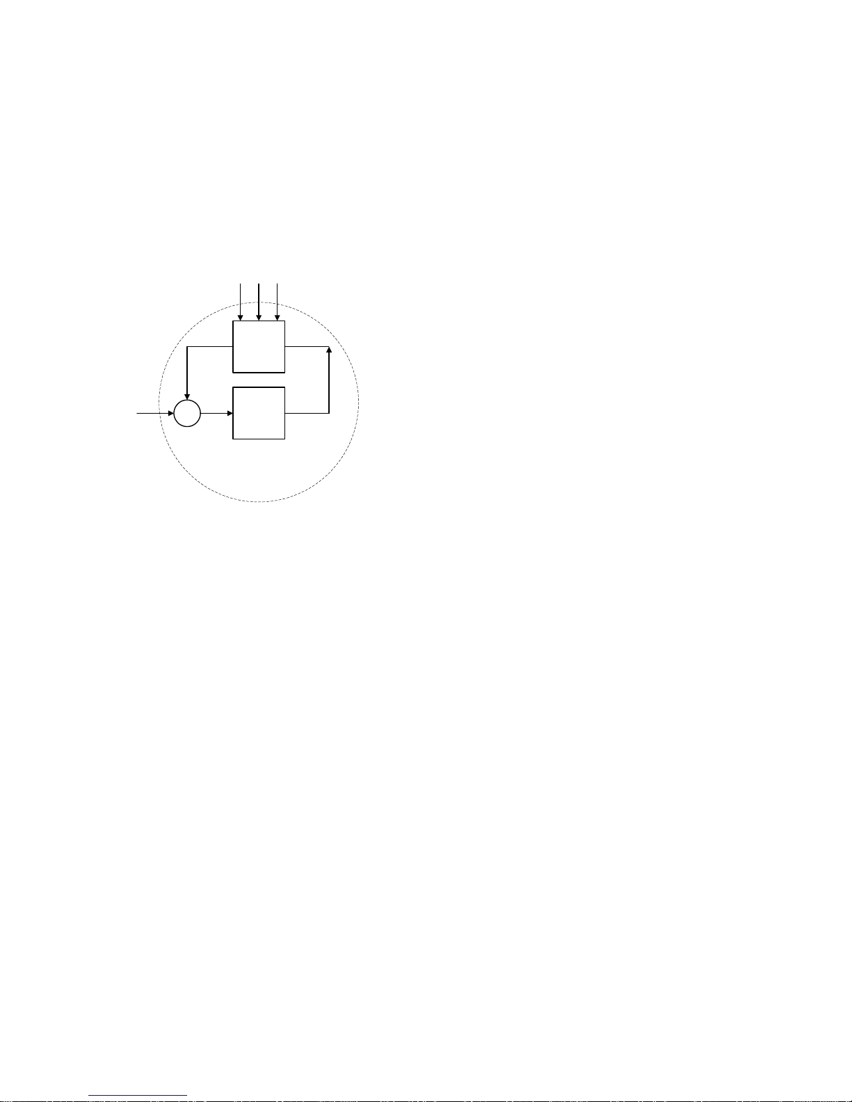
An automatic control system has the function of bringing the output variable x of a controlled
system to a predetermined value and to maintain this value against the influence of disturbances z.
With digital controller, the controlled variable x is measured cyclically and compared with the
command variable w. The resulting negative deviation xd = w - x is processed in the controller to
form the manipulated variable y which acts on the controlled system.
w
2
1
x
y
z
1
xd
z2z
3
w
Command variable
x
Controlled variable
xd
Negative deviation
y
Manipulated variable
z
Disturbance variables
1
Controlled system
2
Controlling means
Fig.1/1 Block diagram of a control loop
1.2 Sensors and Transmitters
The controlled variable may be any physical quantity. Frequently encountered variables in process
engineering are e.g. pressure, temperature, level and flow.
Certain sensors such as resistance thermometers, resistance transmitters and thermocouples can
be directly connected to the controller. Otherwise, transmitters supplying an electric output variable
must be connected between the sensor and the controller. Our controllers are designed for
transmitters with standardized signal outputs (0 to 10 V, 0 to 20 mA or 4 to 20 mA).
1.3 Final Control Elements and Actuators
In most cases in heating and process engineering, the manipulated variable y acts through a valve,
a damper or another mechanical positioning device on the controlled system. Three types of
actuators are possible to actuate such final control elements:
• Electric actuators, consisting of electric motor and gear unit. They have an integral action
and are driven by three-position step controllers. There are also electric actuators with
integrated (series-connected) positioners which then have a proportional action and are
driven by continuous controllers.
• Pneumatic actuators with compressed air as the supply and with electropneumatic positioner
or converter. These have a proportional action and are driven by continuous controllers.
5
Project Planning Manual SIPART DR20
•
Hydraulic actuators with electrically driven oil pump and electrohydraulic positioner. These
have a proportional action and are also driven by continuous controllers.
Electric actuators with single-phase or three-phase motors are robust, economical and require
practically no maintenance.
Pneumatic actuators are faster than electric actuators and are also explosion-proof. However, they
are not particularly suitable for large positioning forces.
Hydraulic actuators are fast and can also be used for large positioning forces, but they are more
expensive than electric or pneumatic actuators.
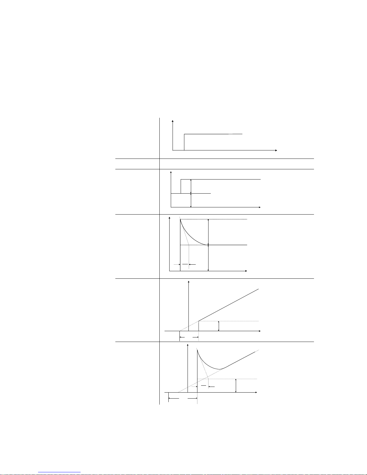
xd
t
step function
control action
step response
P
y
t
Kp ∗ xd
y
0
PD
y
t
Kp ∗ xd
Tv
Vv
Kp ∗ Vv ∗ xd
y0 = 0
PI
y
t
Kp ∗ xd
Tn
PID
y
t
Kp ∗ xd
Tn
Tv
Vv
1.4 Controllers
In the input circuit, the
controlled variable x is
compared with the
command variable W and
the negative deviation xd
is determined. This is
processed with or without
a time response into the
output signal. The output
signal of the amplifier can
represent the manipulated
variable w directly, e.g. if it
controls final control elements or actuators with a
proportional action. With
electric actuators, the
mani- pulated variable y
only appears after the
actuator. The positioning
increments required are
obtained as a PDM signal
from the con- troller output
by conversion.
Depending on the construction of this circuit, the
controller has a
proportional (P),
proportional-differential
action (PD), proportionalintegral action (PI) or
proportional-integraI-differential action (PID).
Fig. 1/2
Step responses with different control actions
6
SIPART DR20 Project Planning Manual
If a step function is applied to the controller input, then step responses corresponding to Fig. 1/2
are produced.
Characteristic values of the P controller are the proportional gain Kp and the working point yo. The
working point is defined as the value of the output signal at which the negative deviation becomes
zero.
In contrast to the P controller, a permanent deviation is avoided in the PI controller, irrespective of
the working point, the setting of the command variable and the variation in the disturbance
variables, by means of an integrating component. The characteristic value of the integrating
component is the reset time Tn.
The PID controller achieves an improvement of the dynamic control performance by the addition of
a D component. The D component is determined by the derivative action gain Vv and the
derivative action time Tv.
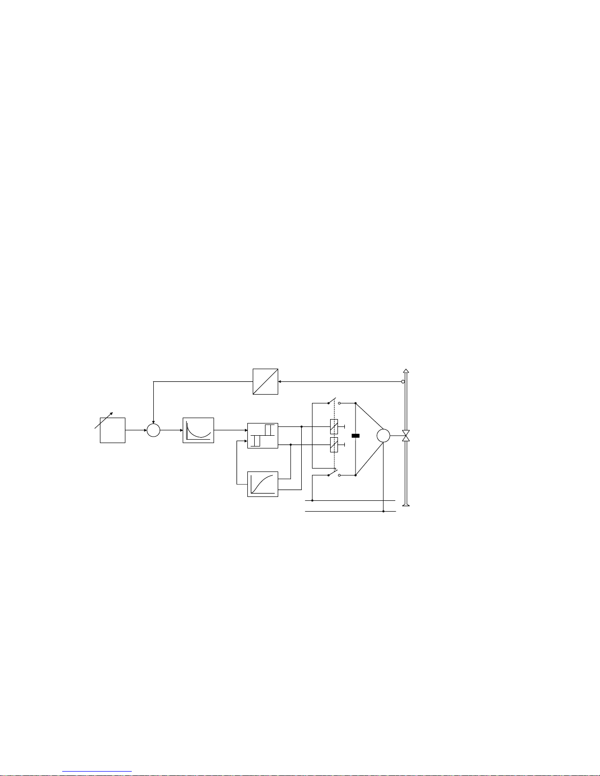
The controller output signals must be matched to the actuators. Two types of controllers are
common for the most important kinds of actuator:
Æ three-position step controllers for electric actuators and
Æ continuous controllers for pneumatic and hydraulic actuators
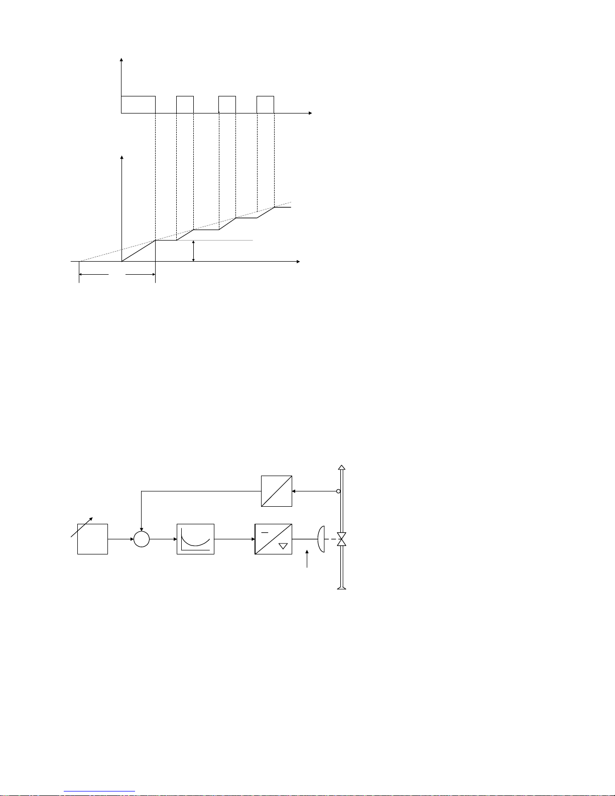
The three-position step controller switches the electric motor of the actuator to clockwise rotation,
stop or counterclockwise rotation by means of relays or semiconductor switches and can affect the
positioning speed of the final control element by means of different on/off ratios.
w
52
x
-
+
xd
3
1
y
x
4
M
L1
N
6
w Command
variable
x Controlled
variable
xd Negative
deviation
y Manipulated
variable
1 Transmitter
2 Setpoint adjuster
3 Three-point
switch
4 Feedback with
time response
5 Control amplifier
6 Final control
element
Fig 1/3 Three-position step controller, functional diagram
The switching performance of the three-point amplifier is reproduced in Fig 1/4 as a pulse diagram.
7
Project Planning Manual SIPART DR20
y
∆y
t
t
Kp ∗ xd
Tn
Kp Proportional gain
Tn Reset time
xd Negative deviation
∆y Manipulated variable
(controller)
y Manipulated variable
(motor)
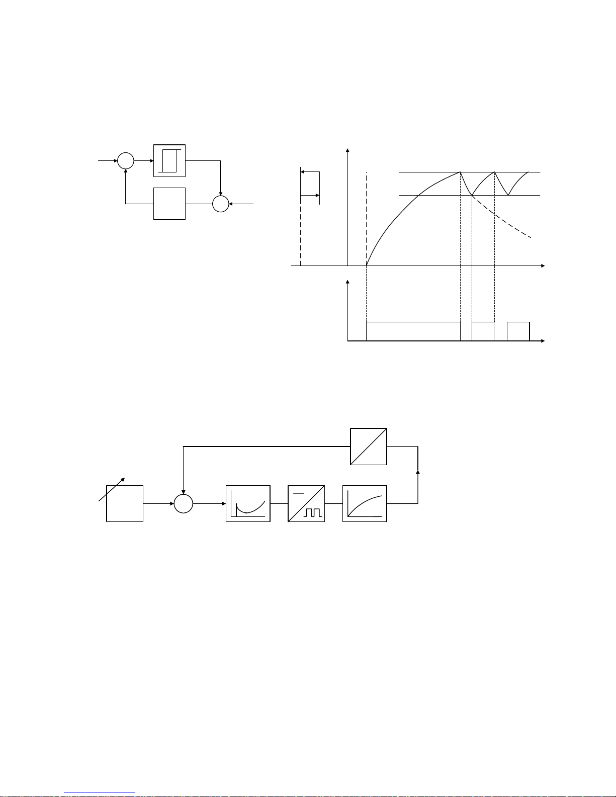
Fig. 1/4 Three-position step controller,
transient function and parameters
The transient function produced at the final control element by these pulses resembles that of a
continuous PI controller. Therefore the parameters Kp and Tn are also applied to the description of
the transient function of three-position step controllers. This is referred to as quasi-continuous
control (see Fig. 1/4).
The response threshold A is adjustable in our controllers. Thus, for example, noise suppression
and a stabilizing effect can be achieved.
The main field of application of continuous controllers is in installations with pneumatic
actuators. The controller output signal of 0 to 20 mA or 4 to 20 mA acts continuously on the final
control element through an electropneumatic signal converter.
w
32
x
-
+
xd
4
1
y
0.2 ... 1.0 bar
y
x
5
0 ... 20 mA
(4 ... 20 mA)
w Command variable
x Controlled variable
xd Negative deviation
1 Transmitter
2 Setpoint adjuster
3 Control amplifier
4 Electropneumatic
signal converter
5 Pneumatic final
control element
Fig. 1/5 Continuous controller,
functional diagram
Two-position or three-position controllers are used to activate relays, contactors or thyristor
switches for switching electric heaters or coolers. The two-position controller (Fig. 1/6) switches, if
the controlled variable goes below the value x1 or above x2. A continuous oscillation occurs whose
frequency depends on the delay time of the controlled system and the switching hysteresis of the
controller.
8
SIPART DR20 Project Planning Manual
Since the control result thus obtained does not completely meet the requirements in most cases,
the switching frequency is increased and the amplitude of the oscillation is thus reduced. The
performance of a P or PI controller can thus be achieved in many cases using a two-position
controller. In the SIPART DR20 the control amplifier is followed by a duty factor converter with
adjustable period, resulting in a PID two- position controller (Fig. 1/7).
w
2
1
x
y
z
+
-
1. Controller
2. Controlled system
x
x1
x2
OFF
ON
y
ON
OFF
t
t
Fig. 1/6 Two-position controller without feedback
w
21
x
-
+
xd
34
5
1. Setpoint adjuster
2. Control amplifier
3. Duty factor converter
4. Controlled system
5. Transmitter
Fig. 1/7 SIPART DR20 two-position controller
In the case of controllers with mechanical contacts, the switching frequency possibly is limited
because of the contact life. However, if thyristor units are used as switching elements, the
switching frequency can be increased.
The control problem often requires the controller action to be divided between various final control
elements or manipulated variables, e.g. for heating and cooling. Two- position controllers are used
for these problems where the manipulated variables are divided into two sections and assigned to
two outputs. An adjustable dead zone is present between the two sections. A duty factor of 0 to
100 % is possibly in each section.
These controllers are also referred to as three-position controllers.
9

Project Planning Manual SIPART DR20
2. The SIPART DR20 Controller
2.1 Application
The SIPART DR20 is a stand-alone process controller for a wide range of applications in process
engineering, mechanical engineering and apparatus engineering. It is available in the following
designs:
• K controller with continuous output
for connection of pneumatic or hydraulic actuators with proportional action
• S controller with step output,
programmable either as:
- three-position step controller for electric actuators
- two-position controller with two outputs for heating and cooling
Its flexibility means that SIPART DR20 is suitable for designing simple control loops as well as for
solving control tasks in meshed controls. It can be used in conventional parallel wiring via its
analog and digital interfaces. In addition, it can be connected to higher-level systems (process
computers or control systems) via an addressable serial interface which can be retrofitted at any
time or incorporated into a central operating and monitoring system with a personal computer and
the SIPART software, if applicable also together with devices from the TELEPERM D range.
The SIPART DR20 can be programmed to the most common types of controller:
• Fixed setpoint controller with and without disturbance variable feedforward at
input and output
• DDC backup fixed setpoint controller
• Follow-up controller with and without local/remote switchover (SPC)
• Synchronization controller for controlled variable
• Ratio controller
In addition, the device can also be used as a ratio station, manual/automatic control station (also
DDC manual control station) and process indicator.
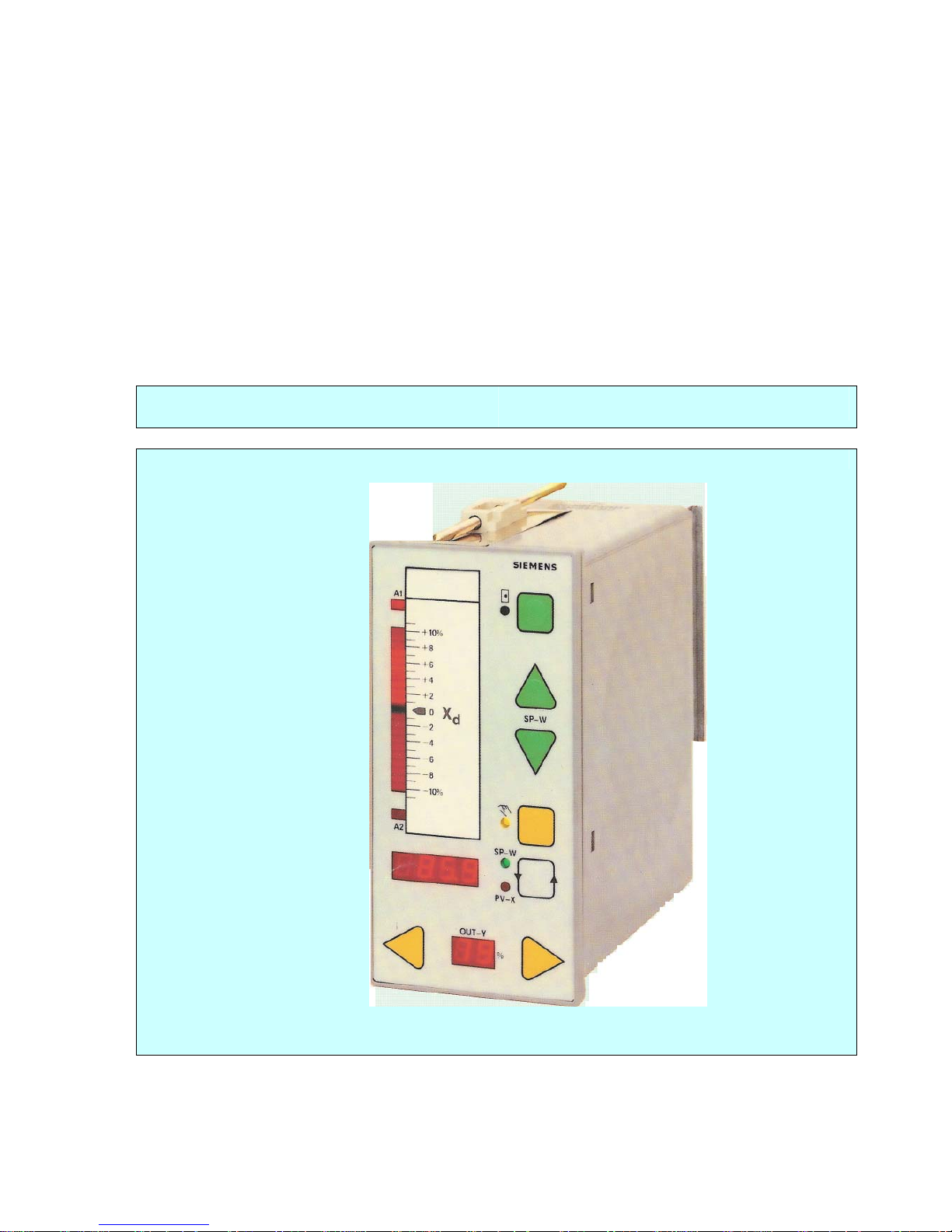
The control and display unit (front module) of the SIPART DR20 is sealed by a plastic foil so that
degree of protection IP 64 is possible with a suitable installation configuration. The mounting depth
of the device is very small so that it is not only suitable for panel and switchboard mounting but
also for direct installation in machines and equipment.
An extremely high reliability for the device has been achieved by extensive and expensive
measures during development and manufacture. In addition to appropriate selection of the
components used, a worst-case design of the circuits and a 24-hour burn-in with subsequent
computer-controlled final test, special measures have been included to provide an interference-free
design of the circuits and high noise immunity towards RF sources.
10
SIPART DR20 Project Planning Manual
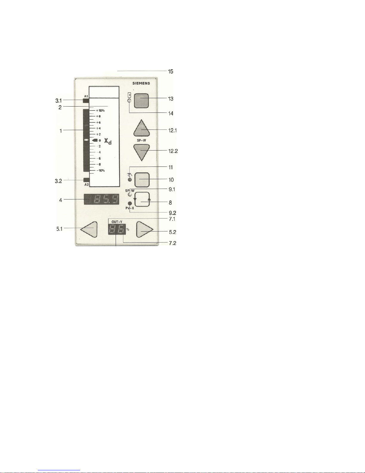
2.2 Operation and Display Functions
1 Negative deviation display
2 Replaceable label
3.1 LED for alarm A1
3.2 LED for alarm A2
4 Digital display for w-x-A2-A1 and for
parameters and configurations
5.1 Manipulated variable adjustment in
manual mode in direction of 0 % display
5.2 Manipulated variable adjustment in manual
mode in direction of 100 % display
6 Digital display of manipulated variable
from - 9 to + 109 %
7.1 Point lights up in S controllers when - ∆y is
switched through
7.2 Point lights up in S controllers when + ∆y is
switched through
8 Selector for digital display 4, for activation
of parameterization/configuring and for
lamp test
9.1 LED lights up if w is output in display 4
9.2 LED lights up if x is output in display 4
10 Selector for manual/automatic mode
11 LED lights up in manual mode, flashes
with remote intervention (N, Si, Bl)
12.1 Pushbutton to increase the local setpoint
12.2 Pushbutton to decrease the local setpoint
13 Selector for local/remote setpoint
14 LED lights up with local setpoint,
flashes with certain SPC and DDC
operating states
15 Cover for scale replacement
Fig. 2/1 Front view
11
Project Planning Manual SIPART DR20
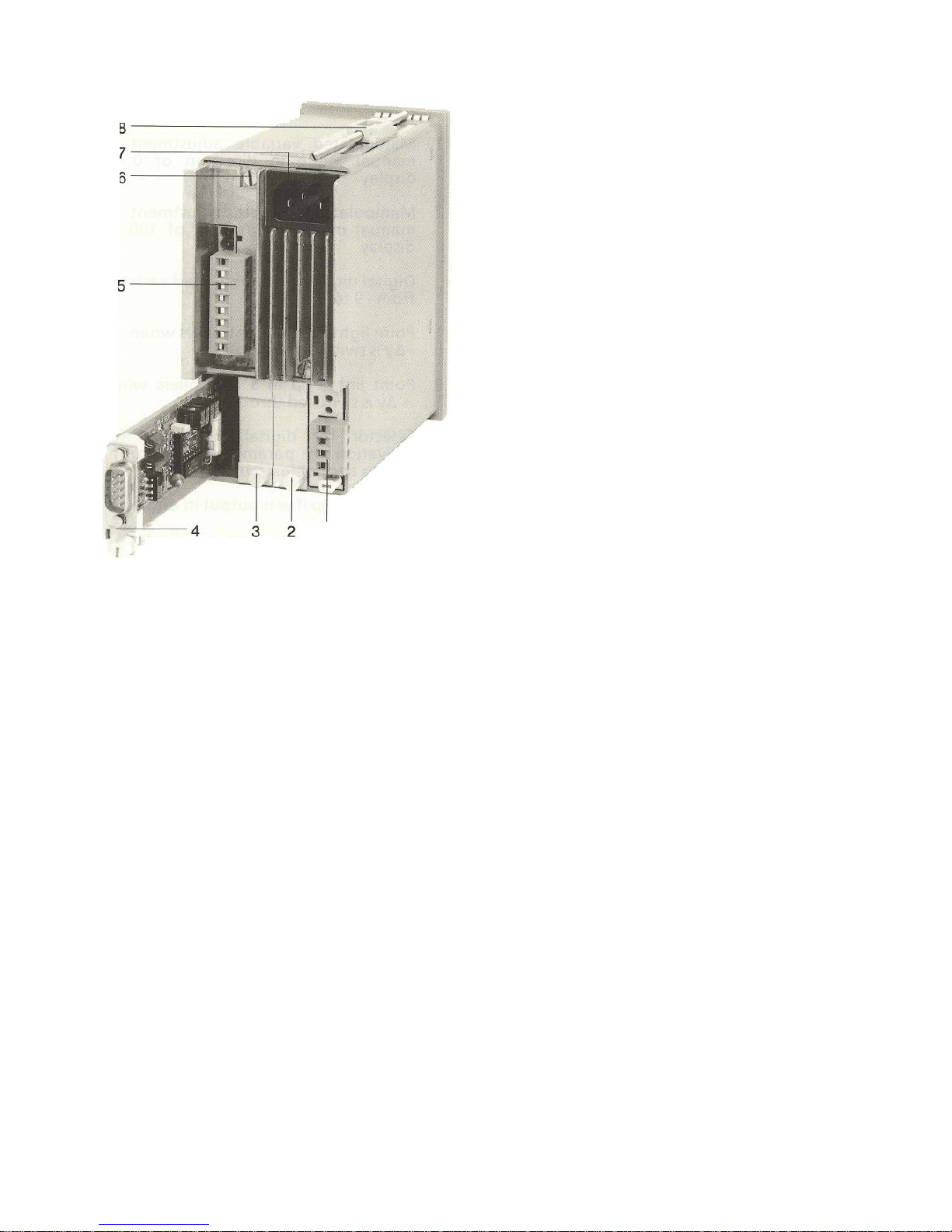
1 Slot AE3, fitted with module
2 Slot AE4, unfitted, with dummy panel
3 Slot GW, unfitted, with dummy panel
4 Slot SES, module pulled out
5 Terminal block of standard controller
6 Earthing screw
7 Mains plug
8 Clamp for fixing the device in a panel;
second clamp underneath device
Fig. 2/2 Rear view of SIPART DR20
12
SIPART DR20 Project Planning Manual
3. Technical Description
3.1 Hardware
The SIPART DR20 process controller is of modular design and therefore easy to service and to
convert or retrofit. It consists of a standard controller in which additional option modules can be
inserted to extend the functions. These option modules are inserted into slots at the rear side of the
closed controller (see Fig. 2/2).
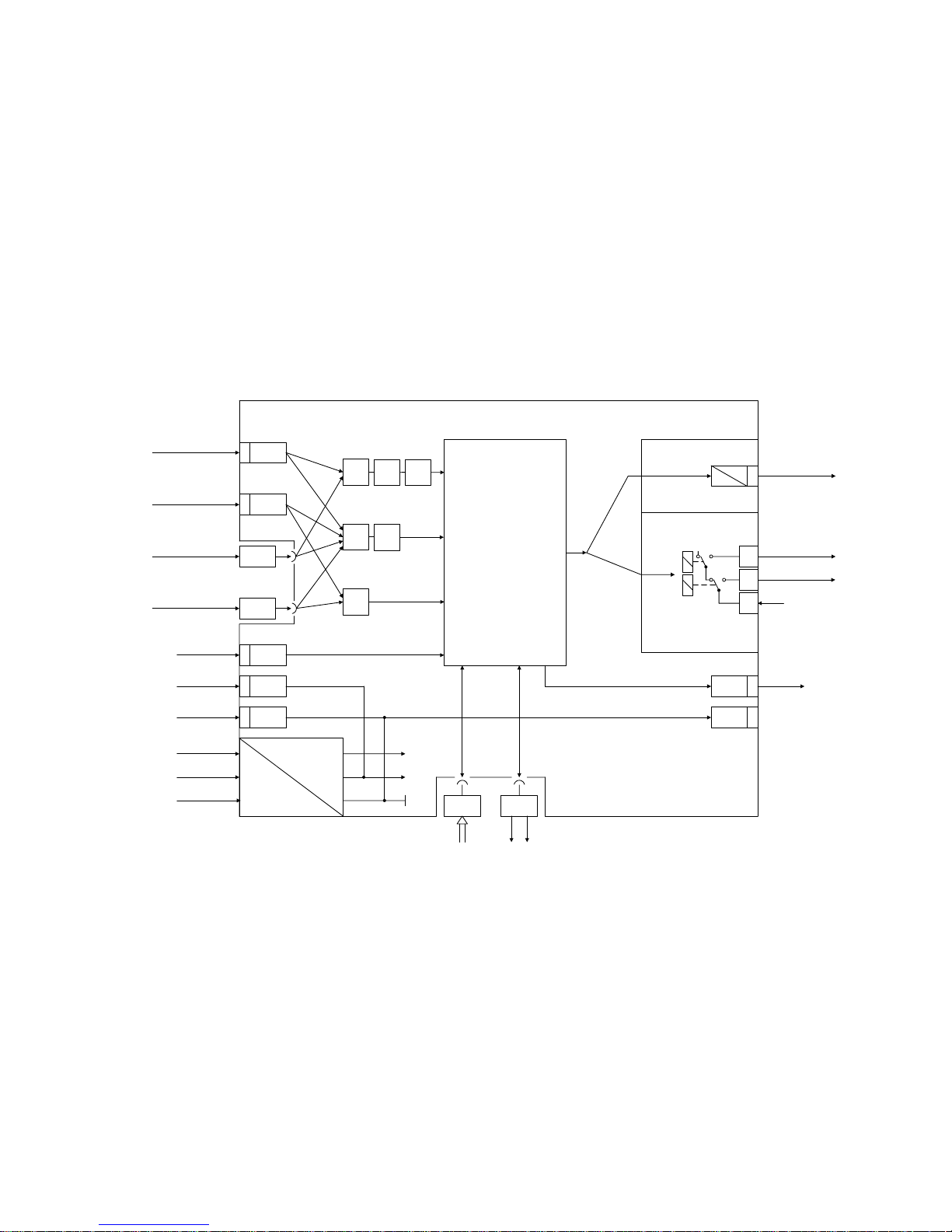
The standard controller contains two non-floating inputs for analog currents. Since other input
signals are sometimes to be processed or a floating condition is desired and the SIPART DR20
can also process three analog input signals simultaneously, two of the rear slots are designed for
fitting with additional input modules. The arrangement of the fixed and optional input signal
converters to the process signals is optional; the possibilities are shown in Fig. 3/1.
AE3
I
0/4 ... 20 mA
0/4 ... 20 mA
I
I - U - R - P - T
I - U - R - P - T
Options
AE4
AE22
AE11
x1
√
lin.
x2
wE
√
yR
yN
BE3
L +5
M6
BE
20 V
M
L
N
PE
SES GW
Options
BA 4
Front panel
with
microcontroller
EPROM and EEPROM
and
control and display
unit
M 7
BA
M
8
K: 6DR2004
S: 6DR2001
+ ∆y / Heating
K --> continous
U
I
Iy
- ∆y / Cooling
0/4 ... 20 mA
y
10
8
9
Two-position/
Two channel or
Three-position step
L
Fig. 3/1 Functional diagram of SIPART DR20
13

Project Planning Manual SIPART DR20
The standard controller comprises :
• a plastic housing with clamps for installation in switchboards, panels or machines
• a front module latched into this housing
• a basic circuit board which can be replaced towards the rear and which contains the output
stage for the K (continuous) or S (step) output and the power supply unit for various
operating voltages.
As already mentioned, a further four signal converter module can also be inserted into the rear of
the device (also during operation). The following are present:
• two slots for analog inputs (AE3 and AE4)
• one slot for alarm outputs with relays (A1/A2)
or
alarm and S outputs via four digital outputs with an additional input for blocking programming
inputs
• one slot for a serial interface module
The mains connection is via a standardized plug for low-power appliances; a special plug is used
for a 24 V connection. All connections for field signals (except serial interface) consist of terminal
strips which can be inserted or removed for each circuit board as a complete block. This enables
prewiring and convenient replacement of modules or controllers. The terminal blocks have different
number of poles and mixing up in a controller is therefore impossible (except AE3 and AE4). All
additional modules are protected against incorrect insertion by mechanical coding of the circuit
boards. The slots are closed by covers if additional modules are not used.
3.1.1 Front module
The front module consists of a plastic frame (material: Macrolon 8320), a printed, water-tight cover
foil (material: Mylar D), a replaceable scale with seals and a circuit board screwed to the frame.
The front module is latched into the housing and can only be removed using a special tool. Plug
connectors are arranged at the rear of the circuit board into which the basic circuit board and the
additional modules are inserted from the rear.
The front circuit board contains the display and control elements and the "intelligence" of the
device. LSI circuits enable a very small volume. The module contains:
• the CPU
• the non-erasable program memory
• the non-volatile data memory for the parameters and configurations entered by the user
• the time base
• the data processing of the serial interface
• the self-monitoring
• the A/D and D/A conversion for all analog variables
• the acquisition and output of digital signals
• the acquisition of input functions and control of the display elements
14

SIPART DR20 Project Planning Manual
All display elements are designed using LEDs thus ensuring a high service life and intensity and a
he controller has a very high number of different functions. All pushbuttons and displays are
d for
.1.2 Basic Circuit Board
he basic circuit board contains the power supply unit and the circuits required to match the field
a transformer power pack for the AC 115 V and AC 230 V designs, a primary switched-mode
• internally required operating and reference voltages
f-scaIe
• he function are
• als. The direction of action and the function are
• d variable signal output for 0/4 to 20 mA. The
or
/cooling)
aution: The relays used are designed to carry a maximum switching voltage of 250 V
good viewing angle. The individual segments are driven in TDM mode. The control elements are
pushbuttons with a short travel, clear point of contact and high resetting force. They are activated
through the foil via a flexible switching board designed such that the foil cannot be over-stressed.
They are scanned in parallel mode by the processor and several pushbuttons can therefore be
activated simultaneously.
T
activated on the front module which are required for the specific function. Elements not require
a particular function have no effect.
3
T
signals of the standard controller to the microcontroller of the front module. This results in the
following function units:
•
power pack for the AC / DC 24 V design
a highly efficient voltage stabilizer for the
• a short-circuit-proof voltage output of 20 V (L +) for transmitters or signal contacts
• two current inputs of 0/4 to 20 mA into 249 Ω without electrical isolation. The start-o
values and the functions can be programmed (see Section 3.2)
a digital input for 24 V logic signals. The direction of action and t
programmable (see Section 3.2)
a digital output for 24 V logic sign
programmable (see Section 3.2)
either a continuous manipulate
start-of-scale value can be programmed
or a switching output with two relays for 230 V / 5 A with a spark suppress
assembly, suitable for two-position controllers with two zones (e.g. heating
or as a three-position step controller for motorized actuators.
C
AC / DC 240 V phase-shift motors, that generate a resonance sharpness of
up to double the rated voltage on the open contact assembly, must therefore
only be driven by suitable separate switching elements !
15

Project Planning Manual SIPART DR20
3.1.3 Additional Modules (Options)
3.1.3.1 Analog Inputs AE 3 and AE 4
As already mentioned and shown in Fig. 3/1, the standard controller can be equipped
with two additional input modules. Definition of the functions and all other programming are
described in Section 3.2. The following signal converters are available:
6DR2800-8J Input module with electronic isolation for standardized current signal of 0/4 to 20 mA
with 49.9 Ω load or voltage signal of 0 to 10 V.
6DR2800-8R Input module for resistance transmitter (potentiometer); the start-of- scale and
full-scale values can be adjusted during operation on the rear of the device. Three
rated resistance ranges (full-scale values) can be preset on the module: 100 to
220 Ω, 200 to 500 Ω and 470 to 1000 Ω. This module can also be used as
a current input without electrical isolation and with adjustable start-of scale and
full-scale values.
6DR2800-8P Input module for connection of a Pt 100 resistance thermometer with a two-wire,
three-wire or four-wire system within a measuring range from -50 to + 850 °C.
Span ≥ 50 °C; the start-of-scale and span values can be set on the module using
jumpers, the fine adjustment of the start-of-scale and full-scale values is made on
the rear of the device during operation. The output is linear.
6DR2800-8T Input module for mV signals or for direct connection of thermocouples. The span is
≥10 mV, the start-of-scale value ≤ 50 mV. The module is electrically isolated. The
start-of-scale and span values are set on the module itself using jumpers. The fine
adjustment is made at the rear of the module during operation. Linearization is
carried out by a function generator in the standard controller. A temperature sensor
fitted to the connection terminal is used for cold junction compensation; an external
cold junction is possible. The following thermocouples according to the new DIN IEC
584 Section 1 can be connected:
Cu-CuNi (type T), Fe-CuNi (type J), NiCr-Ni (type K), NiCr-CuNi (type E), Pt10Rh-Pt (type S),
Pt13Rh-Pt (type R), Pt30Rh-Pt6Rh (type B) as well as types U (Cu-CuNi) and L (Fe- CuNi) to
DIN 43 710.
A further jumper setting determines whether the device input is driven to zero or full-scale in the
event of a thermocouple breakage.
16

SIPART DR20 Project Planning Manual
3.1.3.2 Alarm Outputs GW
The standard controller contains an adjustable alarm monitoring system with two LEDs on the front
module. This circuit can be programmed such that either the controlled variable, command variable
or deviation is monitored. Two additional modules are available for external signalling of the alarms
which can be inserted as options into the standard controller.
6DR2801-8A Output module with two floating (relay) contacts for 24 V 5 A.
The contact assignment can be set using jumpers.
6DR2801-8B Output module with four digital outputs 20 V / 30 mA and an additional digital input.
Two of the digital outputs are for alarms, the manipulated variable signals are output
via the two other outputs in the S controller. In this case the output relays in the
standard controller for output of the manipulated variable pulses are switched off. If
the digital input of this module is connected to L+ of the standard controller (or to
another 24 V supply), the parameterization and configuring facilities via the front
module of the device are blocked.
3.1.3.3 Serial Interface (SES)
6DR2803-8A Interface module to connect the SIPART DR20 to a serial data bus. The levels of
this data bus are based on V.28; switching to V.28 point-to-point communication is
possible using a jumper. Using this module, the device can transmit and receive
process variables, operating states, parameter settings and configuring switch
positions. Up to 32 SIPART DR controllers can be connected in parallel to a bus
line. Combinations with TELEPERM D devices are also possible if the control of the
higher-level computer allows this. A bus driver C73451-A347-B202 must be
connected into the transmission line if more than three bus interfaces are to be
connected together or if the transmission is to be via a line of more than 50 m.
SIPART bus signals can be transmitted over distances up to 500 m; 20 mA current
loop signals (TTY level) are transmitted over larger cable lengths - up to 1000 m.
A separate power supply (± 24 V 100 mA) must be provided for the bus driver if only
SIPART DR controllers are operated on a bus line. A TELEPERM D device can
supply the bus driver if SIPART DR and TELEPERM D controllers are connected
simultaneously to the bus line.
17

Project Planning Manual SIPART DR20
3.2 Software
The program of the SIPART DR20 operates with a fixed cycle time of 100 ms. A process image is
generated at the start of each routine. The analog and digital inputs and actions on the front keys
are acquired and the process variables transferred which are received from the serial interface. All
calculations are carried out on these input signals according to the stored functions. The data are
then output to the display elements, the D/A converter and the digital outputs and the calculated
variables are stored ready for the transmitter of the transmission interface. The program is
interrupted every 20 ms in the S controllers in order to switch off the S outputs to obtain a good
resolution. Data transfer is also executed in interrupt mode.
The ROM of the SIPART DR20 contains a large number of dedicated functions for the control of
process plants, machines and apparatus. The user can program the controller by selecting the
desired functions using the configuring switches. The total controller function results from the
combination of individual configuring switches. Programming knowledge is not required for the
settings. All settings are made on the front of the SIPART DR20 without an additional programmer.
The problem-specific program produced in this manner is stored in the non-volatile part of the data
memory and is therefore protected against power failure.
There are 48 configuring switches (S1 to S48). A setting corresponding to the desired function can
be selected for each switch from a function table.
The factory settings of the configuring switches are always "0". This corresponds to the most
common setting of the individual functions so that only a few switches need be set selectively in
most cases during start-up. It is always advisable, however, to compare the compatibility of the
various configuring switch positions with the actual problem.
Configuring switches 1 and 2 are of fundamental importance. S1 is used to define the type of
controller and thus the signal processing and linking at the input as well as the switching response
of the output circuit. S2 is used to define the output configuration. The functions of the following
configuring switches S3 to S40 correspond to the logical sequence of signal processing. Switches
S41 to S48 are used to define general functions such as restart conditions and data transmission
via the serial interface.
The complete configuring switch table (Table 3/1) follows on the next pages. Detailed information
is then provided on the individual functions and links.
18

SIPART DR20 Project Planning Manual
Structuring
switches
and
positions
Function
S1
0
1
2
3
4
5
6
7
8
9
10
Device type
Fixed setpoint controller
Fixed setpoint controller with disturbance
variable feed-forward at input
Fixed setpoint controller with disturbance
variable feed-forward at output
DDC back-up fixed setpoint controller
Slave controller without local/ remote switchover
Slave controller with local/remote switchover and
SPC via the serial interface
Synchronization controller without local/remote
switchover
Ratio controller
Ratio station (only in “K” version)
Manual/automatic control station and manual
control device, DDC manual control device
Process indicator K: with setpoint value output
Process indicator S with 2nd limit monitor
S2
0
1
2
3
Output structure
K output (0/4 to 20 mA)
S output. two-step controller with 2 outputs for
heating/cooling
S output. three-pos. step controller for motoroperated devices, internal position feedback
S output. three-pos. step controller for motoroperated devices. external position feedback
Basic positions
S3
0
1
Mains trequency suppression
For 50 Hz
For 60 Hz
S4
0
1
Input signal from AE1:
0 to 20 mA
4 to 20 mA
S5
0
1
Input signal from AE2:
0 to 20 mA
4 to 20 mA
S6
0
1
Input signal from AE3:
0 to 20 mA or U, R, P, T
4 to 20 mA
S7
0
1
Input signal from AE4:
0 to 20 mA or U, R, P, T
4 to 20 mA
S8
0
1
Allocation of the analog inputs to the main
controlled variable X1
AE 1 (0/4 to 20 mA without electrical isolation)
AE 3 (option for I/U, R, P, T)
Analog inputs
S9
0
1
Allocation of the analog inputs to the position
feedback Y
R
or position tracking YN:
AE 2 (0/4 to 20 mA without electrical isolation)
AE 4 (option for I/U, R, P, T)
Table 3/1 Configuring switches
Structuring
switches
and
positions
Function
S10
-2
-1
0
1
Allocation of the analog inputs to the auxiliary
controlled variable X2/command variable X2
(ratio control) or remote setpoint WE:
AE1 (0/4 to 20 mA without electrical isolation)
AE2 (0/4 to 20 mA without electrical isolation)
AE3 (option for I/U, R, P, T)
AE4 (option for I/U, R, P, T)
S11
0
1
2
3
4
5
6
7
Transmitter monitoring
None
X1 - X2/wE X1 X2/wE -
- - Y
R/YN
X1 - YR/Y
N
- X2/wE YR/Y
N
X1 X2/wE YR/Y
N
S12
0
1
Root extraction of main controlled variable X1:
No
Yes
S13
0
1
Root extraction of X2:
No
Yes
Analog inputs
S14
0
1
Linearization of main controlled variable X1:
No
Yes
S15
0
1
2
3
4
5
Function of the digital input BE
BL blocking of manipulated output
Si safety value of manipulated
variable y = yS
N tracking of the output y = yN
CB computer ready signal
BE on serial interface
BLPS Block parameterization /
structuring
CB without
acknowledgement
6
7
8
9
10
11
BL blocking of manipulated output
Si safety value of manipulated
variable y = yS
N tracking of the output y = yN
CB computer ready signal
BE on serial interface
BLPS Block parameterization /
structuring
CB with
acknowledgement
Analog inputs
S16
0
1
Sense of the digital input BE:
13 to 30 V = logical 1
0 V / open = logical 1
S17
0
1
x-tracking (w = x, wv = xv) in H, N, DDC, BI
and Si operation
No
Yes
S18
0
1
Setpoint w with CB failure:
Local w
Safety setpoint w
s
Setpoint control
S19
0
1
Tracking of the local setpoint wi to the effective
setpoint w
Yes
No
19

Project Planning Manual SIPART DR20
Structuring
switches
and
positions
Function
S20
-1
0
1
2
Decimal point in display 4 for SP-PV-A2-A1
(ineffective with S1=7 and 8)
x x x x
x x x. x
x x. x x
x. x x x
Display
S21
-3
-2
-1
0
1
2
OFF
Repetition rate of the digital display:
0.1 sec
0.2 sec
0.5 sec
1.0 sec
2.0 sec
5.0 sec
display 4 switched OFF, indicator 6: 0.1 sec
S22
0
1
2
Input of the limit monitors:
S1 = 0 to 6, 9, 10 ⏐ 7, 8____
Xd ⏐ Wv – Xv
2)
X ⏐ Xv
W ⏐ Wv
S23
0
1
2
Function of the alarm monitors:
A1 = max. and A2 = min.
A1 = min. and A2 = min.
A1 = max. and A2 = max.
Alarm signalling
S24
0
1
Setting the alarm monitors:
Only in the parametrization level
Also in the process operation level
Xd display
S25
-2
-1
0
1
2
OFF
3
4
5
6
7
Display range of the display 1:
± 2.5 %
± 5.0 %
± 10 %
± 20 %
± 40 %
Display switched OFF
± 40 %
± 20 %
± 10 %
1)
± 5.0 %
± 2.5 %
S26
0
1
Sense of the controller in the controlled system
Normal (cP > 0) referred to
Reversed (cP < 0) Xd = w-x
S27
0
1
2
3
D element input
Xd
X
X2/W
E
direction of action against X
X2/W
E
direction of action with X
Algorithm
S28
0
1
Control algorithm
PI (D)
P (D)
Structuring
switches
and
positions
Function
S29
0
1
Priority N (DDC), BL or H:
N (DDC), BL
H
S30
0
1
2
Manual mode with transmitter fault (S11):
Switchover does not take place to manual mode
Starts with last manipulated variable
Starts with safety manipulated variable
Output switchover
S31
0
1
2
Blocking of the manual/automatic switchover:
No
Only automatic operation, switchover to manual
mode not possible
Only manual operation with interlocking (the ∆y
readjustment facility can be switched off by key
10,
LED 11 then does not light up)
S32
0
1
OFF
Manipulated variable display:
Control output Y
Feedback signal Y
R
No display
Y Display
S33
0
1
Sense of position display on the controlled system
Normal (Y-display = Y or Y
R
)
Reversed (Y-display = 100%-Y or 100%-Y
R
)
S34
0
1
2
3
4
Function of the digital output BA:
/RC Controller not in computer mode
H Controller in manual mode
/RB Controller not in computer standby
MuSt Transmitter fault
BA is activated via the serial interface
Digital output BA
S35
0
1
Sense of the digital output BA:
Logical 1 = 24 V
Logical 1 = 0 V
Alarm components
S36
0
1
Components supplied with the optional module
GW:
Alarm outputs:
Controller supplied with module 6DR2801-8A Æ 2
relays for A1/A2, or GW is not used
Controller supplied with module
6DR2801-8B Æ 4 digital outputs for A1, A2 and
± ∆y, and 1 digital input for blocking of parameterization and structuring (the relay outputs ± ∆y of
basic device have no function)
S37
0
1
Current output Iy of the K controller
(only with S2 = 0):
0 to 20 mA
4 to 20 mA
K controller
S38
0
1
Iy switch-off with DDC operation
(only with S2 = 0 and S1 = 3 or 9):
No
Yes
Table 3/1 Configuring switches (continued)
1)
Software release – A08 or greater
2)
Software release – A09 or greater
20

SIPART DR20 Project Planning Manual
Structuring
switches
and
positions
Function
S39
-9
-8
-7
:
:
-1
0
1
:
:
8
9
10
Minimum control pulse length te
(only with S2 = 2 or 3)
20 ms
40 ms
60 ms
:
:
180 ms
200 ms
220 ms
:
:
360 ms
380 ms
400 ms
S-controller
S40
-9
-8
-7
:
:
-1
0
1
:
:
8
9
10
Min. control pulse pause ta (function as S39)
20 ms
40 ms
60 ms
:
:
180 ms
200 ms
220 ms
:
:
360 ms
380 ms
400 ms
S41
0
1
2
3
Restart conditions after power failure:
Automatic operation, remote, with the last w
or wv, y begin, with y
S
with S controllers
(S2 = 2 and 3) with the last position
Automatic operation, local,
with w = w
s
or wv = wvS, y as S41 = 0
Manual operation, remote, with the last or wv
and y = y
S
with S controllers (S2 = 2 and 3)
with the last position
Manual operation, local
with w = w
S
or wv = wvS, y as S41 = 2
With flashing of display 4
Startup conditions
4
5
6
7
Automatic operation, remote, with the last w or
wv, y begins with y
s
, wIth S controllers (S2 = 2
and 3) with the last position
Automatic operation, local,
with w = w
s
or wv = wvs, y as S41 = 0
Manual operation, remote, with the last w or wv
and y = ys, with S controllers (S2 = 2 and 3)
with the last position
Manual operation, local
with w = w
s
or wv = wvs, y as S41 = 2
Without flashing of
display 4
Structuring
switches
and
positions
Function
S42
0
1
2
Serial interface, only in conjunction with optional
module 6DR2803-8A:
Without; controller transmits all variables, receives
none
With; controller transmits all variables, receives
only parameters and structuring switches
With; controller transmits all variables, receives
parameters, structuring switches and W
es
, Yes,
STes (CB, BL, Si and BA
)
S43
0
1
2
3
4
5
Data transmission rate:
9600 bit/s
4800 bit/s
2400 bit/s
1200 bit/s
600 bit/s
300 bit/s
S44
0
1
Vertical parity:
Even
Odd
S45
0
1
2
Longitudinal parity position:
Without
After ETX
Before ETX
S46
0
1
Longitudinal parity:
Normal
Inverted
S47
0
1
2
:
:
31
Station number (address):
0
1
2
:
:
31
Serial interface
S48
0
1
2
3
:
:
24
25
Time monitoring CB
ES
:
Without
1 s
2 s
3 s
:
:
24 s
25 s
Table 3/1 Configuring switches (continued)
The following sections demonstrate and describe hardware and software functions in the form of
function diagrams. The sequence of diagrams largely corresponds to the sequence of configuring
switches except that the input signal processing is handled before the diagrams of the possible
settings of the configuring switch S1 (device types) to enable better understanding of the
subsequent diagrams.
21
Project Planning Manual SIPART DR20
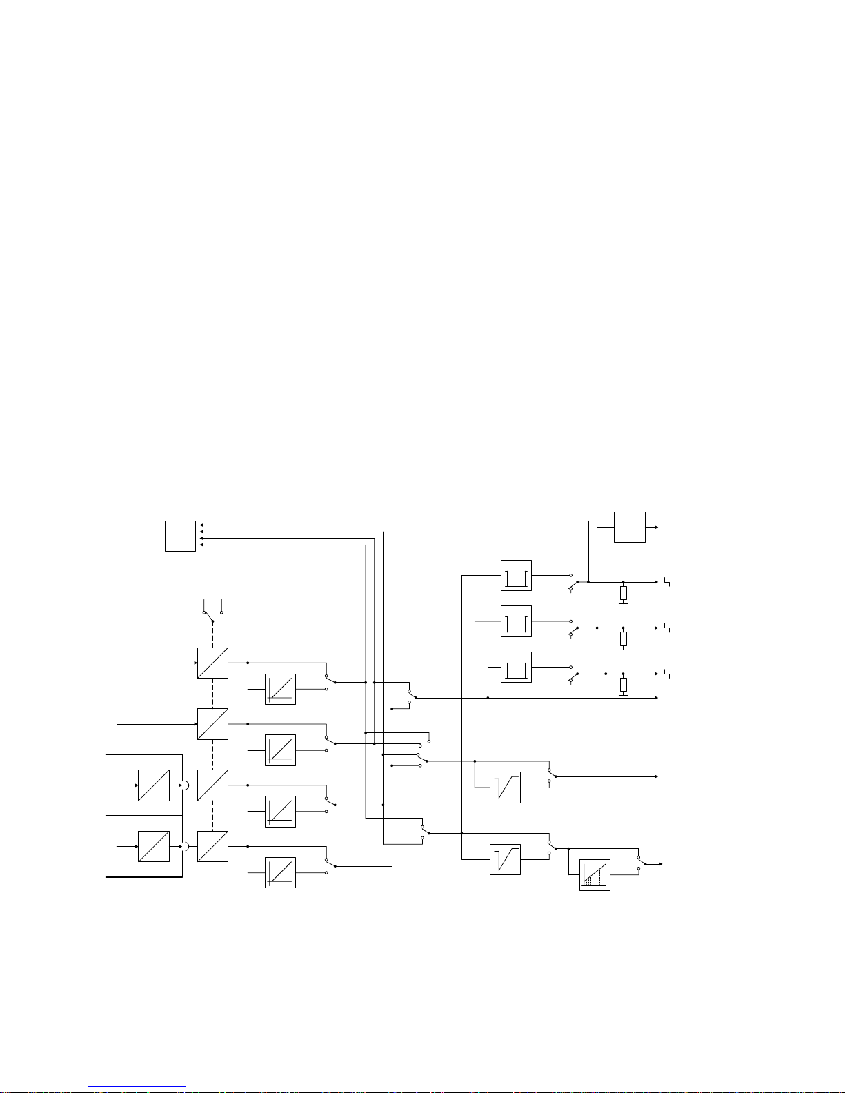
3.2.1 Input Signal Processing (Figs. 3/2 and 3/3)
Analog-to-digital conversion is carried out using a quasi-integrating measurement. All analog
inputs are converted approximately 120 times within 20 or 16.67 ms and the results averaged so
that the mains frequency and its harmonics can be filtered out. This adaptation to the mains
frequency is made using configuring switch S3.
0/4 to 20 mA switchover: The configuring switches S4 to S7 are used to define whether the
measuring range starts at 0 or 4 mA. The corresponding switches must be left in position 0 if nonstandardized signals (potentiometers, thermocouples, Pt100) are connected to AE3 and AE4 and
with 0 to 10 V signals.
Signal assignment: Up to three analog input variables can be processed for the control tasks of
the device:
• Main controlled variable x1
• Remote setpoint wE / command variable x2 with ratio controller / disturbance variable x2
• Position feedback yR / position tracking yN
The four analog inputs AE1 to AE4 are assigned to these variables using the configuring switches
S8, S9 and S10. The unused inputs can be scanned via the bus interface, transmitter monitoring
does not take place, however.
S4
1
0
SES
0/2/4/6
1/3/5/7
S11
-2
U
U
A
D
AE4
A
D
AE3
A
D
AE2
A
D
AE1
S3
50 Hz 60 Hz
4 .. 20 mA
4 .. 20 mA
4 .. 20 mA
4 .. 20 mA
S5
1
0
S6
1
0
S7
1
0
S9
0
1
S10
0
1
-1
S8
0
1
S12
0
1
S13
0
1
x2/wE
x1
yR/yN
1
S14
0
LA, L1, .. L7, LE
-3 .. 103%
-3 .. 103%
-3 .. 103%
2/3/6/7
0/1/4/5
MuSt
1
2
Y
Fault signal
on display 4
4/5/6/7
0/1/2/3
Fig. 3/2 Processing of analog input signals
22

SIPART DR20 Project Planning Manual
Transmitter monitoring:
The measured values processed in this manner can be assigned to the monitoring circuit using
configuring switch S11. If one or more of the monitored variables violates the limits of -3 or
+103 %, the following is monitored on the four-digit display: " 1", " 2" or " Y". This message
remains until acknowledged using the pushbutton 8 (Fig. 2/1). The value which was last displayed
then appears again. If several inputs are faulty simultaneously, all are monitored simultaneously.
As shown, all individual signals are “OR”-ed together in addition. The fault message "MuSt" can be
transmitted via the digital output or the serial interface. It is simultaneously available for
programmed switchover to manual mode.
Square-root extraction:
The position of configuring switches S12 and S13 determines whether the controlled variables x1
and x2/wE are square-rooted. Negative input values are not square-rooted; in this case the output
value is set to zero.
Linearization:
The main controlled variable x1 can be linearized if required; this is selected using configuring
switch S14. Linearization is carried out using a polygon characteristic with eight straight lines
(see page 91 for setting and example).
The linearization circuit must always be used in the case of non-linear input values since
intermediate values can only be indicated correctly on the digital display in this manner. The
control response is also improved.
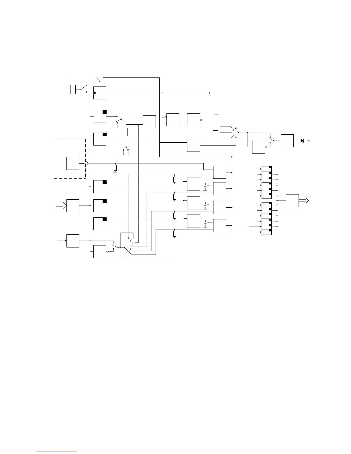
Digital input BE:
The controller has a digital input which acts normally (digital signal ≥ 13 V = logical 1) or inverted
(digital signal ≤ 4.5 V or open-circuit = logical 0) according to the position of configuring switch
S16. The function is assigned to the digital input by configuring switch S15 which has been
extended in software version A06 / A07:
Configuring switch
position of S15
Function of digital input
0 BL Blocking of manipulated variable. The last manipulated
variable current is retained in the K controller, the last duty
factor (heating or cooling output) is retained in the twoposition controller. A manipulated variable signal is no longer
output in the three-position step controller.
1 Si Safety manipulated variable. The manipulated variable
assumes the parameterized safety value (yS) in the K
controller, two-position controller and three-position step
controller with external position feedback. In the threeposition step controller with internal simulation of the position,
the manipulated variable tends towards zero if the
parameterized safety value is less than 50 %, and towards
100 % if the parameterized safety value is equal to or greater
than 50 %.
CB without acknowledgement
23

Project Planning Manual SIPART DR20
Configuring switch
position of S15
Function of digital input
2 N Tracking of output. In the K controller and two- position
controller, the output stage is isolated from the control
algorithm by this signal and directly connected to the input
yN. The manipulated variable or the duty factor is then
determined by this input signal. Tracking is not possible in
the three-position step controller.
3 CB Computer readiness. In the DDC backup controller, the
controller is set to backup mode by this signal, in SPC
controllers, SPC mode is then started. The CB signal can
also be used for controlled two-setpoint or three-setpoint
mode.
4 SES A digital input signal does not trigger a function in the
controller but is transmitted via the serial interface.
Functions can then be triggered or displayed in a higherlevel system.
5 BLPS The parameterization and configuring facility via the front
module of the controller is blocked by means of a digital
signal. Unauthorized adjustments to parameters or
configuring switches can then be prevented.
CB without acknowledgement
6 BL Blocking of manipulated variable, function as "Switch
position 0”
7 Si Safety manipulated variable, function as "Switch position 1"
8 N Tracking of output, function as "Switch position 2"
9 CB Computer enabled, function as "Switch position 3"
10 SES The binary input only acts on the serial interface, function as
"Switch position 4"
11 BLPS Blocking of parameters and configuring switches, function
as "Switch position 5"
CB with acknowledgement
Only one of these functions can be processed via the digital input BE of the controller.
The non-selected functions therefore have defined signal states as follows:
CB = 1 with S42 = 0 or 1 BL = Si = N = SES = BLPS = 0
CB = 0 with S42 = 2
The digital functions BL, Si, N and CB can be addressed in parallel via the serial interface if
configuring switch S42 is in position 2.
Acknowledgement of CB signal:
The controller is immediately switched to computer mode in positions 0 to 5 of the configuring
switch S15 with a CB switchover from 0 to 1 and with the front panel key 13 in position "Remote",
i.e. the controller operates "Without CB acknowledgement".
24
SIPART DR20 Project Planning Manual
The device is switched to local mode with configuring switch positions 6 to 11, a CB switchover
from 0 to 1 and with front switch 13 in position "Remote". The computer coupling is only achieved
again by manual switching back to remote mode. The controller operates "With CB
acknowledgement".
Option module
6DR2801-8B
INT
INT
CB
ES
S42
0/1
·
S15
0 ... 5
6 ... 11
local
S42
≥
2
0/1
2
+
BE
ES
BE
NE
ES
Si
ES
Bl
ES
SES
BE
&
&
RC
H
RB
MuSt
SES
BA
0
1
S35
CB
S34
≥
&
&
≥
2
≥
≥
&
BLPS
N
Si
Bl
S16
0
1
0/6
1/7
4/10
3/9
5/11
2/8
S15
S42
S42
S42
2
2
0/1
0/1
0/1
0
1
2
3
4
SES
BL
MuSt
INT
A2
A1
H
yE
CB
Si
N
BE
PS
Fig. 3/3 Digital functions via digital input/output and the serial interface (including status signals)
3.2.2 Input Signal Processing and Switchover
The following functions are explained in this section:
• Manual setpoint input w
i
or setpoint ratio wv
• x-tracking
• Setpoint limiting and setpoint ramp
• Formation of negative deviation
• Alarm monitor
• Digital display of setpoint and actual value or the setpoint and actual ratio factor
and the limits
and, depending on the possible types of devices:
• Switchover and calculation of the setpoint w or the setpoint ratio factor
• Calculation of the controlled variable x
25

Project Planning Manual SIPART DR20
General, repeatedly encountered functions:
Manual setpoint input w
i
or setpoint ratio wv:
The setpoint wi can be adjusted using the S and T push buttons (12) in the controller types with a
facility for local setpoint adjustment providing the green LED next to the local/remote selector (13)
indicates "Iocal mode" and the green LED next to the display selector (8) indicates "Display of
setpoints". The adjustment is made every 0.1 s in steps with 0.01 %. The step size is increased
linearly with time so that larger ranges of adjustment can also be covered in a reasonable time. If
the adjustment is interrupted by releasing the pressed pushbutton, it can then be started again with
the smallest rate of adjustment. An adjustment over the complete measuring range lasts approx.
7 s.
x-tracking:
It is possible to provide x-tracking for all types of controllers using configuring switch S17 = 1. This
means that the setpoint is made equal to the actual value and the setpoint ratio to the actual ratio
and tracked as soon as, and also as long as, the control loop is isolated in the output of the device
by manual, tracking, DDC backup mode or by y-blocking or a safety manipulated variable
(identified by /A = no automatic mode in the function displays). Thus when returning to automatic
mode, the control loop can be closed without bumps and drift with xd = 0. The setpoint may have
changed in the process.
Setpoint limit and setpoint ramp:
In all controller types the setpoint or the setpoint ratio can be limited by the parameters wa and we
within the measuring range adjusted. In the ratio controller and ratio station, the range of
adjustment of the ratio factor is defined by these parameters (page 38).
The rate of change can be adjusted using the parameter Tw (tS). The time Tw refers to a change
in setpoint over the complete measuring range. The setpoint ramp is always effective except with
x-tracking.
The setpoint ramp can be adjusted between 1 and 9984 s, but only between 1 and 100 s in the
ratio controller and ratio station (S1 = 7 and 8).
Formation of negative deviation:
The negative deviation is calculated from the effective setpoint w and the effective actual value x:
xd = w - x
and is the negation of the deviation x
w
. Further processing is described in Section 3.2.3 (page 43).
Alarm monitor: This can be used to monitor the minimum and/or maximum values of a variable.
The variable to be monitored is selected using configuring switch S22, the type of monitoring is
selected using configuring switch S23. Configuring switch S24 defines whether the alarms are to
be set only in the parameterization level or also in the operation level of the device.
26

SIPART DR20 Project Planning Manual
The alarms A1 and A2 are indicated on the four-digit display (4) in the same engineering units as
the setpoint and actual value. The hysteresis is 1 % of the measuring range.
Caution: In addition to monitoring on the instrument, alarm signals can also be output
externally using an additional module (page 80). It should be noted that only one
external alarm signal is output at a time.
For example, if the alarm monitors have been programmed for max./max. signalling
(preliminary alarm and main alarm), the preliminary alarm signal is cancelled when the
main alarm signal appears. This only applies to external alarms via an optional module
and not to LED signals on the front panel of the controller.
Digital display of setpoint and actual value or setpoint ratio and actual ratio and limits:
The setpoint, actual value and limits are indicated in engineering units where the start-of-scale
value is scaled by parameter LA and the full-scale value by LE. The factory setting is LA = 0.0 and
LE = 100.0 corresponding to a percentage scale. Configuring switch S20 can be used to adjust the
position of the decimal point, S21 the repetition rate of the displays.
With software version A06 / A07 it is also possible to set the full-scale value LE below the start-ofscaIe value LA, i.e. to operate the controller with falling characteristic of the actual value.
The setpoint ratio, actual ratio and limit setting are displayed with ratio controllers and ratio
stations. The decimal point is fixed at x.xxx so that ratio factors are possible between 0.000 and
9.999 (cf. S1 = 7 and 8).
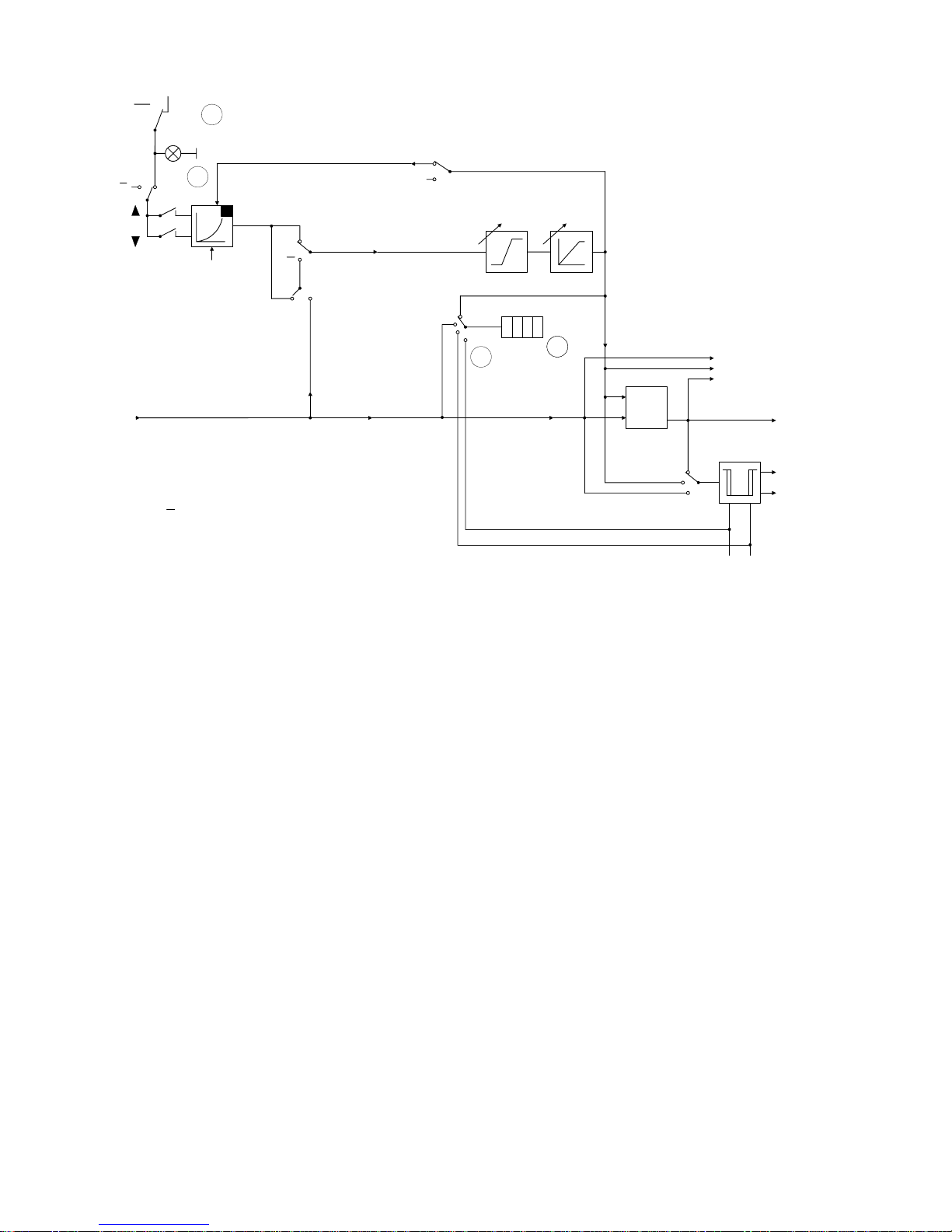
Functions which depend on the configured type of controller:
• S1 = 0 Fixed setpoint controller (Fig. 3/4)
In this type the controller only processes the main controlled variable x1 as an analog input signal.
The setpoint can be adjusted using the setpoint pushbuttons (12) if the two green LEDs (9.1 and
14) light up on the front of the device, i.e. with local mode and setpoint display. It is thus possible to
block the intentional or unintentional adjustment of the setpoint by pressing pushbutton (13) (LED
14 then does not light up). The x-tracking function (with manual or tracking mode or with blocking
of the manipulated variable or safety manipulated variable) is independent thereof, i.e. x-tracking
(with S17 = 1) is effective with and without LED 14).
In line with the definition of the fixed setpoint controller, the device does not accept an external
setpoint with this programming.
27
Project Planning Manual SIPART DR20
X1
INT
+
INT
gn
SP - w
w
i
ww
w
i
w
a
w
e
T
w
X
00 00
S20, S21
Display
Key
8884
+
-
SES
W
X
Xd
0
2
1
S23
A2
A1
a1 a2
S17
x - tracking
Key
Key
13
888
0
1
0
1
S19
8888
A
A
A = H or N or Bl or Si
Fig. 3/4 Processing of command variable and formation of the negative deviation with a fixed
setpoint controller
• S1 = 1 Fixed setpoint controller with disturbance variable feed-forward at the input
(Fig. 3/5)
The constant c1 (zero offset) and the disturbance variable x2(r) which can be apportioned using c2
are added to the main controlled variable x1 (r, 1) which can be processed further as the controlled
variable x:
x = x1 + c1 + c2 ∗ x2
The calculation is made between 0 and 100 %. The constants c1 and c2 can be set as parameters
between -199.9 % (corresponds to number -1.999) and +199.9 % (corresponds to number
1.999).
The effective controlled variable x is displayed in the selected measuring range LA to LE.
If only "dynamic disturbance variable feed-forward" is required, the constant c2 is set to 0 and the
input variable x2 applied directly to the D element via configuring switch S27 (see Section 3.2.3
- D element).
28

SIPART DR20 Project Planning Manual
X1
INT
+
INT
gn
SP - w
w
i
ww
X2
w
i
w
a
w
e
T
w
X
00 00
S20, S21
Display
Key
8884
+
-
SES
W
X
Xd
0
2
1
S23
A2
A1
a1 a2
D-element (S27)
see Fig. 3/19
S17
x - tracking
Key
Key
13
888
0
1
0
1
S19
8888
A
A
X1 + c1 + c2 ∗ X2
c1 c2
A = H or N or Bl or Si
Fig. 3/5 Processing of command variable, calculation of controlled variable and
formation of negative deviation with fixed setpoint controller and disturbance
variable feed-forward at the input
• S1 = 2 Fixed setpoint controller with disturbance variable feed-forward at the output
Fig. 3/3 also applies to processing of the command variable and formation of the deviation. The
evaluation and the addition of the disturbance variable to the output signal are described in Section
3.2.3 (page 44).
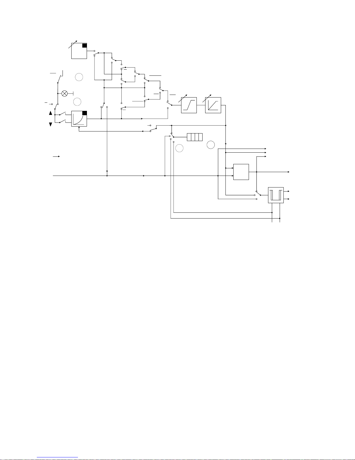
• S1 = 3 DDC backup fixed setpoint controller (Fig. 3/6)
In the case of direct digital control (DDC) all control functions are transferred directly from a
process computer (control system), but individual loops, or all loops, are frequently protected by
parallel hardware controllers. Their function is to take over control of the respective loop in a
hitchless manner if the computer fails. During DDC mode (non-faulty), the backup controllers are at
standby, i.e. their outputs are made to track the respective computer manipulated variable. The
negative deviation can also be set to zero in the individual controllers by x-tracking so that control
is continued in a hitchless manner as well as driftfree following switchover.
29
Project Planning Manual SIPART DR20
X1
w
S
INT
+
INT
gn
SP - w
w
i
ww
X2
1
0
S18
w
i
CB
CB
INT
INT
w
awe
T
w
0
1
X
00 00
S20, S21
Display
Key
8884
+
-
SES
W
X
Xd
0
2
1
S23
A2
A1
a1 a2
D-element
S17
H
H
1
0
S17
x - tracking
Key
Key
13
888
H
S29
Si v Bl
Si v Bl
Si v Bl
H
H
01
0
1
S19
8888
S19=1
is not used
Fig. 3/6 Processing of command variable and formation of negative deviation with DDC backup
fixed setpoint controller
DDC mode corresponds to tracking mode of other types of controller except that the switchover to
tracking mode is not made via the control signal N but as a function of the CB signal (also possible
via the serial interface) and the local/remote selector pushbutton:
DDC mode = RC = CB ∗ /I (with S29 = 0, see Fig. 3/7)
DDC mode = RC = CB ∗ /I ∗ /H (with S29 = 1, see Fig. 3/8)
No status LED lights up on the controller in DDC mode. The value which becomes effective upon
computer failure is always indicated as the setpoint. If the computer fails (CB = 1 Æ 0), the green
LED of the "Local" display (14) flashes and the controller continues to operate with the displayed,
internal setpoint. After switching over to local mode (green LED 14 steady), the setpoint can be
adjusted manually. A clear display of the optical signals is shown in Fig. 3/34 on page 59.
The switchover in the output circuit is explained in the description of section 3.2.4. The following
tables (Figs. 3/7 and 3/8) provide a complete summary of the signals and the effective setpoints
and manipulated variables depending on the front-panel signals, control signals and configuring
switches S17, S18 and S29. The version in Fig. 3/7 is used if manual mode is to be selected
directly following a computer failure.
30
 Loading...