

Siemens SION 3AE Operating Instructions Manual
SION®
Vacuum circuit breaker 3AE
Instructions for assembling and disassembling ten-pole
X01 and X02 connectors
OPERATING INSTRUCTIONS
General
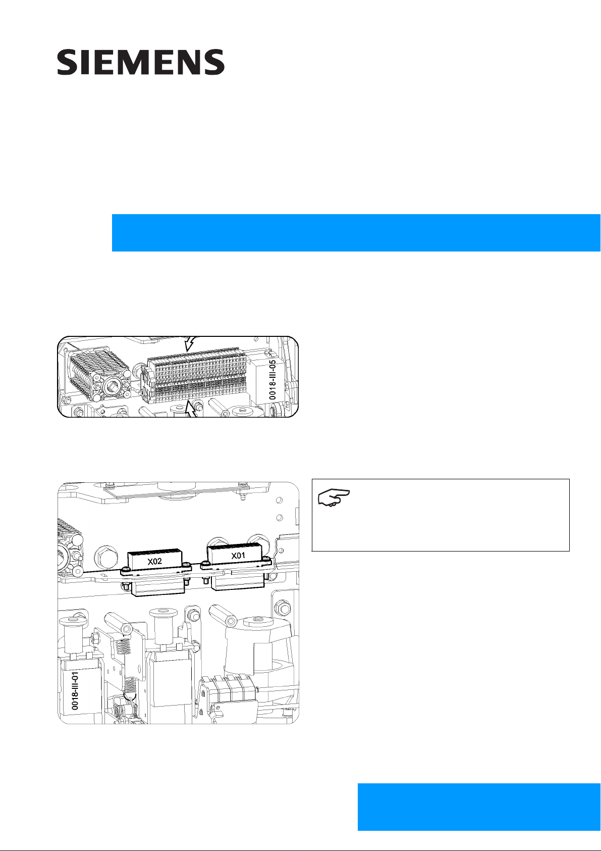
These operating instructions describe how to assemble and disassemble the ten-pole X01 and X02 connectors. In
doing so, it is possible to wire the upper parts of the ten-pole X01 and X02 connectors in such a way that the lowvoltage interface is connected to the signaling switch in the plug-in unit.
Fig. 1 Terminal strip with the ten-pole X01 and X02
connectors located behind
Disassembly
Note
For clearer orientation, the terminal strip is no longer
illustrated in Fig. 2 to Fig. 4.
1. Disassemble and remove the shrouding cover and
cover for the low-voltage interface (see vacuum circuit breaker 3AE 9229 0001 176 operating instructions, chapter entitled "Disassembling and assembling covers").
Fig. 2 Position of the ten-pole connectors (illustra-
tion without terminal strip)
© Siemens AG 2010. All rights reserved.
Order no.: 9229 0018 176 0Ordering location: E D MV C S
AG 01.2011 en
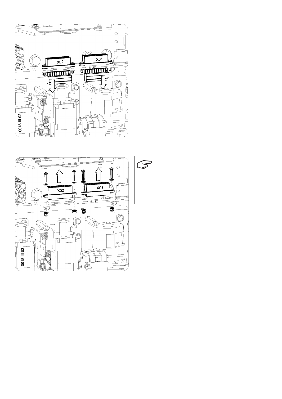
2. Pull the lower parts of the X01 and X02 connectors
downward.
Fig. 3 Pulling the lower parts of the connectors
downward
Fig. 4 Disassembling the upper parts of the con-
nectors
Note
Nuts and washers may fall into the drive of the SION
vacuum circuit breaker.
Secure nuts and washers so that they do not fall down.
3. If necessary, secure nuts (x4) and washers (x8)
using a magnetic socket, to ensure that they do not
fall down and disassemble them.
4. Pull the upper parts of the X01 and X02 connectors
upward.
®
Assembly
Assembly is carried out in reverse order and should be performed using new self-locking nuts (from the accessories pack).
Tighten the Phillips screws using a tightening torque of 1.4 ±0.1 Nm. Exceeding the tightening torque will result in
damage to the plug flanges.
Published by
Published by
Energy Sector
Power Distribution Division
Medium Voltage Components
Berlin Schaltwerk switchgear factory
D - 13629 Berlin
 Loading...