

Page 1

SINUMERIK 840C
SIMODRIVE 611-D
Diagnostics Guide 09.2001 Edition
User Documentation
Page 2

Page 3
Valid for
09.2001 Edition
SINUMERIK 840C
SIMODRIVE 611–D
Diagnostics Guide
Alarms 1
Diagnostics on the PLC 2
Error Display on CPU 3
Errors with Function Macros 4
Parameterization Errors
Spindle/Axis 5
Control Drive
SINUMERIK 840C/CE
(Standard/Export version)
SIMODRIVE 611–D
Software Version Software Version
1.x
2.x
3.x 1.x
4.x 2.x
5.x 3.x
6.x 4.x
6.4 5.x
Page 4

SINUMERIK documentation
Printing history
Brief details of this edition and previous editions are listed below.
The status of each edition is shown by the code in the “Remarks” column.
Status code in the “Remarks” column:
A New documentation.. . . .
B Unrevised reprint with new Order No.. . . .
C Revised edition with new status. . . . .
If factual changes have been made on the page since the last edition, this is
indicated by a new edition coding in the header on that page.
Edition Order No. Remarks
09.95 6FC5198–5AB40–0BP0 A
04.96 6FC5198–5AB40–0BP1 C
08.96 6FC5198–5AB40–0BP2 C
07.97 6FC5198–6AB40–0BP0 C
01.99 6FC5198–6AB40–0BP1 C
09.01 6FC5198–6AB40–0BP2 C
This manual is included in the documentation on CD–ROM (DOCONCD)
Edition Order No. Remarks
11.01 6FC5 198–6CA00–0BG2 C
Trademarks
SIMATIC
R
, SIMA TIC HMIR, SIMA TIC NETR, SIROTECR, SINUMERIKR and SIMODRIVER are trademarks
of Siemens AG. All other product and system names are registered trademarks of their respective
companies and must be treated accordingly.
For further informationvisit our Internet address:
http://www.ad.siemens.de/sinumerik
This publication was produced with Interleaf V 7
The reproduction, transmission or use of this document or its
contents is not permitted wihout express written authority. Offenders
will be liable for damages. All rights, including rights created by patent
grant or registration of a utility model or design, are reserved.
Siemens AG 1996–2001. All rights reserved.
Other functions not decribed in this documentation might be
executable in the control. This does not, however, represent an
obligation to supply such functions with a new control or when
servicing.
We have checked that the contents of this document correspond to
the hardware and software described. Nonetheless, differences might
exist and therefore we cannot guarantee that they are completely
identical. The information contained in this document is, however,
reviewed regularly and any necessary changes will be included in the
next edition. We welcome suggestions for improvement.
Subject to change without prior notice.
Siemens–AktiengesellschaftOrder No. 6FC 5198–6AB40–0BP2
Printed in the Federal Republic of Germany
Page 5

11/92
Siemens AG 2001 All rights reserved 6FC5198–jAB40
SINUMERIK 840C / SIMODRIVE 611–D (DA)
Preliminary notes
This Guide serves as a reference work. It allows the machine tool user:
S to assess irregularities during operation at the machine correctly
S to obtain information about the response of the system to the irregularity
S to make use of the options for continuing operation after the irregularity
Scope This description lists the diagnostics options of the PLC and the alarms of the
MMC, NCK, servo and drive (SIMODRIVE 611–D) areas.
Sequence In the Diagnostics Guide the alarms are sorted in ascending order of alarm num-
bers. The numbers are not necessarily contiguous.
Safety
!
Danger
Please assess the condition of your plant carefully against
the description of the alarm that has occurred. Eliminate
the cause of the alarm and acknowledge it as described.
If alarms are ignored, danger to the machine, workpiece,
stored settings, and in certain cases, to your health, could
result.
!
Warning
This warning notice means that loss of life, severe personal
injury or substantial material damage can result if the
appropriate precautions are not taken.
!
Caution
This warning notice (with warning triangle) means that
a minor personal injury can result if the appropriate precautions are not taken.
Caution
This warning notice (without warning triangle) means that a
material damage can result if the appropriate precautions
are not taken.
Notice
This warning notice means that an undesired event or an
undesired state can result if the appropriate notices are not
observed.
Page 6

12/93
Siemens AG 2001 All rights reserved 6FC5198–jAB40
SINUMERIK 840C / SIMODRIVE 611–D (DA)
Page 7

Contents
1 Alarms 1–1. . . . . . . . . . . . . . . . . . . . . . . . . . . . . . . . . . . . . . . . . . . . . . . . . . . . . . . . . . . . . . . . .
1.1 Alarm groups 1–1. . . . . . . . . . . . . . . . . . . . . . . . . . . . . . . . . . . . . . . . . . . . . . . . . . . . . . . . . . . .
1.2 Alarm numbers/cancellation of alarms 1–2. . . . . . . . . . . . . . . . . . . . . . . . . . . . . . . . . . . . . . .
1.3 Display of the alarms in the alarm line 1–4. . . . . . . . . . . . . . . . . . . . . . . . . . . . . . . . . . . . . . .
1.4 Display of the alarms as dialog box 1–6. . . . . . . . . . . . . . . . . . . . . . . . . . . . . . . . . . . . . . . . .
1.5 Priority of alarms 1–8. . . . . . . . . . . . . . . . . . . . . . . . . . . . . . . . . . . . . . . . . . . . . . . . . . . . . . . . .
1.5.1 Alarm description 1–8. . . . . . . . . . . . . . . . . . . . . . . . . . . . . . . . . . . . . . . . . . . . . . . . . . . . . . . . .
1.6 Dialog text 1–223. . . . . . . . . . . . . . . . . . . . . . . . . . . . . . . . . . . . . . . . . . . . . . . . . . . . . . . . . . . . . . .
1.6.1 Notes for the operator 1–223. . . . . . . . . . . . . . . . . . . . . . . . . . . . . . . . . . . . . . . . . . . . . . . . . . . . .
1.6.2 Listing of dialog texts 1–223. . . . . . . . . . . . . . . . . . . . . . . . . . . . . . . . . . . . . . . . . . . . . . . . . . . . . .
2 Diagnostics on the PLC 2–1. . . . . . . . . . . . . . . . . . . . . . . . . . . . . . . . . . . . . . . . . . . . . . . . .
2.1 Error numbers (ACCU 3 high byte, DB 1 DW 160) 2–1. . . . . . . . . . . . . . . . . . . . . . . . . . . .
2.2 Additional error information (ACCU 3 low byte, DB 1 DW 161–163) 2–7. . . . . . . . . . . . . .
3 Error Display on CPU 3–1. . . . . . . . . . . . . . . . . . . . . . . . . . . . . . . . . . . . . . . . . . . . . . . . . . . .
4 Errors with Function Macros 4–1. . . . . . . . . . . . . . . . . . . . . . . . . . . . . . . . . . . . . . . . . . . . .
5 Parameterization Errors Spindle/Axis 5–1. . . . . . . . . . . . . . . . . . . . . . . . . . . . . . . . . . . . .
Page 8

Page 9
04/96
Siemens AG 2001 All rights reserved 6FC5198–jAB40
1–1
SINUMERIK 840C / SIMODRIVE 611–D (DA)
1 Alarms
1.1 Alarm groups
NC alarms The alarms are divided into alarm groups.
S General alarms
S Computer link alarms
S Axis-specific alarms
S Spindle-specific alarms
S Channel-specific alarms
At POWER ON RESET (switching on control), all
NC alarms are cancelled.
The CANCEL alarms can be deleted in the associated operating area only .
PLC alarms
The PLC alarms are assigned error numbers
6000 to 9999. The alarm text, alarm action and
deletion conditions are configured by the machine manufacturer.
MMC alarms
MMC alarms do not interrupt an active NC
program. The alarms are acknowledged
automatically provided the correct sequence of
operations is adhered to or via softkeys.
1 Alarms
9.1.1 Alarmgruppen
Page 10

04/96
Siemens AG 2001 All rights reserved 6FC5198–jAB40
1–2
SINUMERIK 840C / SIMODRIVE 611–D (DA)
1.2 Alarm numbers/cancellation of alarms
Alarm number
Kind of alarm
1 General alarms
2 to 15 General alarms
16 to 36 Computer link alarms
43 to 1 10 General alarms
1000 to 121 1
1240 to 1251
Axis-specific alarms
1280 to 1371 Axis-specific alarms
1440 to 1971 Axis-specific alarms
2000 to 2193 General alarms
2250 to 2263 Spindle-specific alarms
2270 to 2273 Spindle-specific alarms
2280 to 2283 Spindle-specific alarms
3000 to 3220 General alarms
4000 to 4299
5000 to 5299
Cycle alarms
6000 to 9999 PLC error messages or PLC operational messages
10000 to 12031 Axis-specific alarms
20000 to 20309 Spindle-specific alarms
100000 to 169999 MMC alarms
200000 to 209999 PLC dialogs
210000 to 219999 Free area
300000 to 399999 611D alarms
1 Alarms
1.2 Alarm numbers/cancellation of alarms
Page 11
04/96
Siemens AG 2001 All rights reserved 6FC5198–jAB40
1–3
SINUMERIK 840C / SIMODRIVE 611–D (DA)
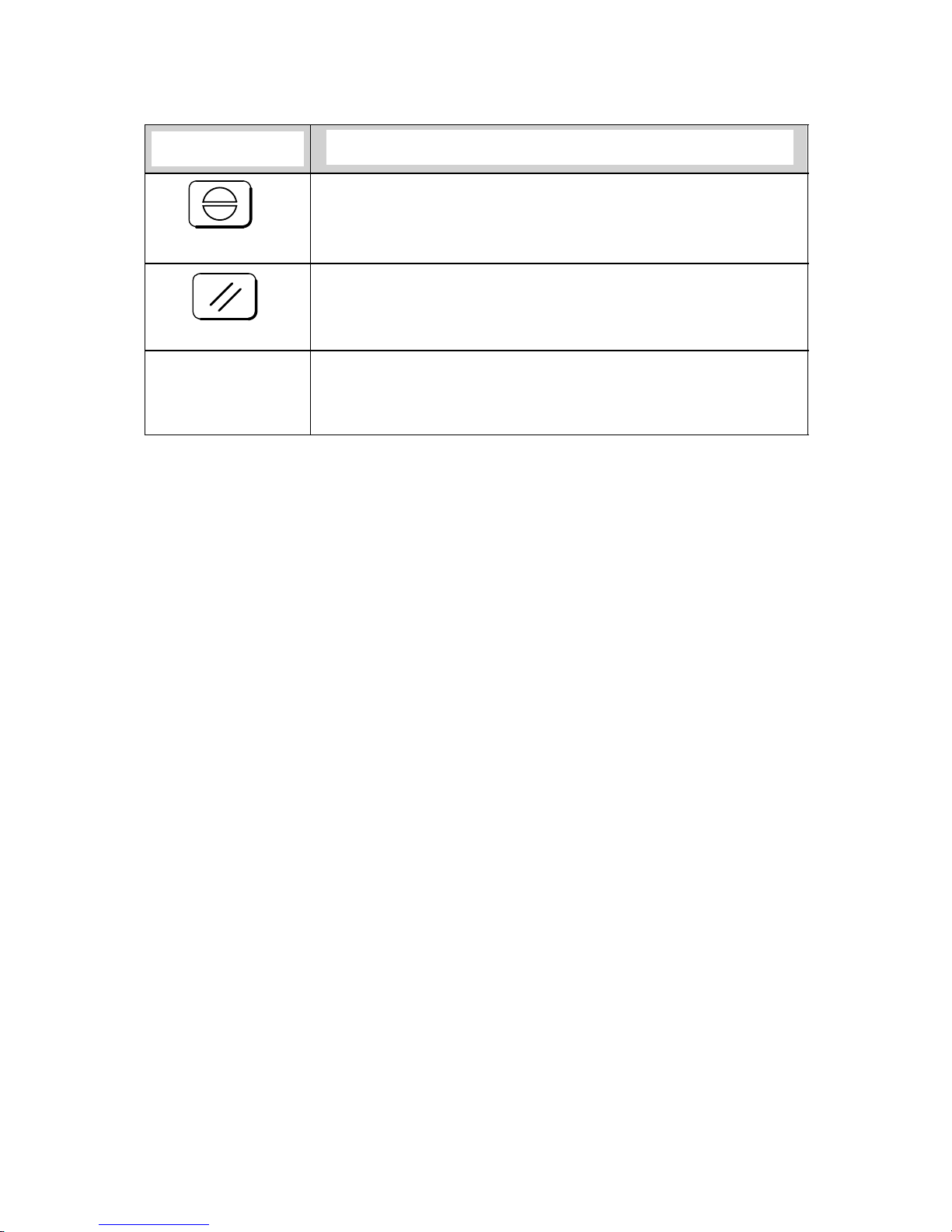
Key
Effect of cancelling alarms
Acknowledgement
An active NC program is not aborted but only stopped.
After eliminating the error, it is possible to continue execution of the NC program from the point at which it was stopped.
Reset
Execution of an active NC program is aborted. After eliminating the error, the
NC program must be restarted.
POWER ON Execution of the active NC program is aborted. After eliminating the error, the
NC program must be restarted and the reference points must be reapproached.
Caution! On switching off the control, the contents of the NCK part program
memory are lost.
POWER ON means switching off the control and switching it on again.
Please note the information provided by the machine tool manufacturer.
1 Alarms
1.2 Alarm numbers/cancellation of alarms
Page 12
04/96
Siemens AG 2001 All rights reserved 6FC5198–jAB40
1–4
SINUMERIK 840C / SIMODRIVE 611–D (DA)
1.3 Display of the alarms in the alarm line
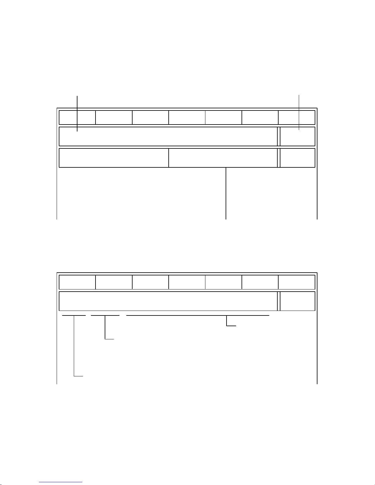
Messages from the monitoring system are displayed in the alarm line. Existing
comments are overwritten by alarm texts. The alarm line is the second display
line from the top.
Machine Parameter Programm. Services Diagnosis
AUTOMATIC
Program stop
M. grp.: 1
Channel: 1
POWER
ON
Actual
values
Distances to
go
Program pointer
%1234
N1234
L1234 N1234P12
X 10.789
Y 5.231
Z 210.643
100.000
10.000
200.000
Alarm line
Delete error condition
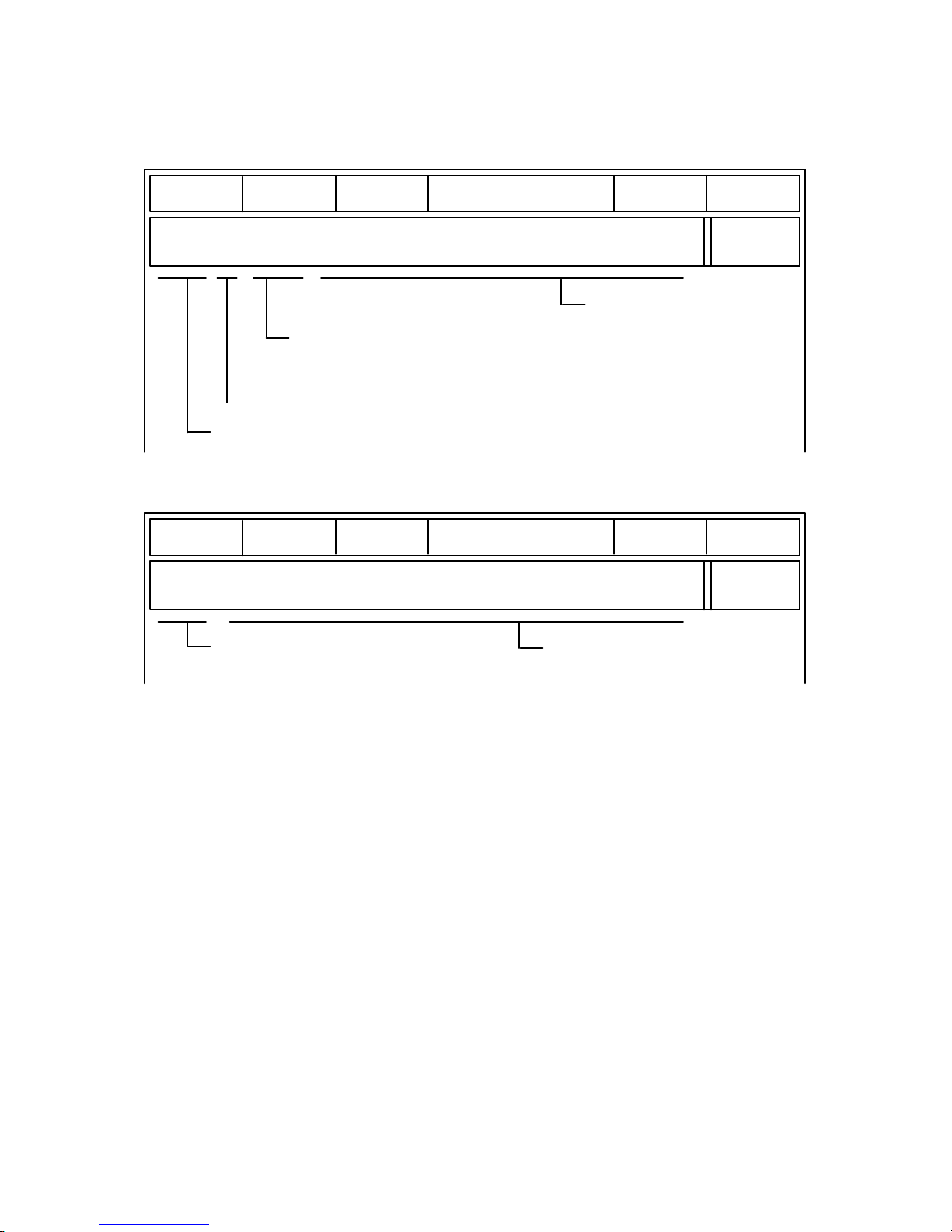
There are three types of display representation for alarm messages: Types A, B
and C.
Example of display Alarm display in sequence order
representation Type A:
Machine Parameter Programm. Services Diagnosis
10243 ORD 5 X Illegal pulse multiplication
max. 6 characters for alarm number
max. 5 characters for ordinal number
The ordinal number shows the order
in which the alarms have occurred.
max. 40 characters
for explanatory text
(for single-line alarm)
max. 100 characters
(for two-line alarm)
1 Alarms
1.3 Display of the alarms in the alarm line
Page 13
04/96
Siemens AG 2001 All rights reserved 6FC5198–jAB40
1–5
SINUMERIK 840C / SIMODRIVE 611–D (DA)
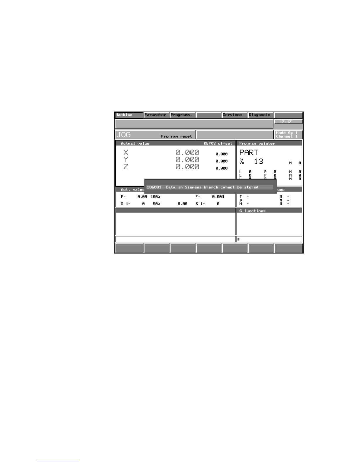
Example of display Alarm display in block number order
representation Type B:
Machine Parameter Programm. Services Diagnosis
3000 1 N0045 General programming error
max. 5 characters for alarm number
max. 5 characters for block number
E.g.: the error has occurred in block N0045.
max. 38 characters
for explanatory text
(for single-line alarm)
1 character for channel number
Example of display
representation Type C:
Machine Parameter Programm. Services Diagnosis
6000 Hydraulic oil min.
max. 4 characters for alarm number
max. 47 characters
for explanatory text
(for single-line alarm)
1 Alarms
1.3 Display of t h e a l a r m s i n t h e a l a r m line
Page 14
04/96
Siemens AG 2001 All rights reserved 6FC5198–jAB40
1–6
SINUMERIK 840C / SIMODRIVE 611–D (DA)
1.4 Display of the alarms as dialog box
The machine tool manufacturer can configure whether the alarm messages are
displayed in the alarm line or in a dialog box. MMC messages are displayed as a
dialog box.
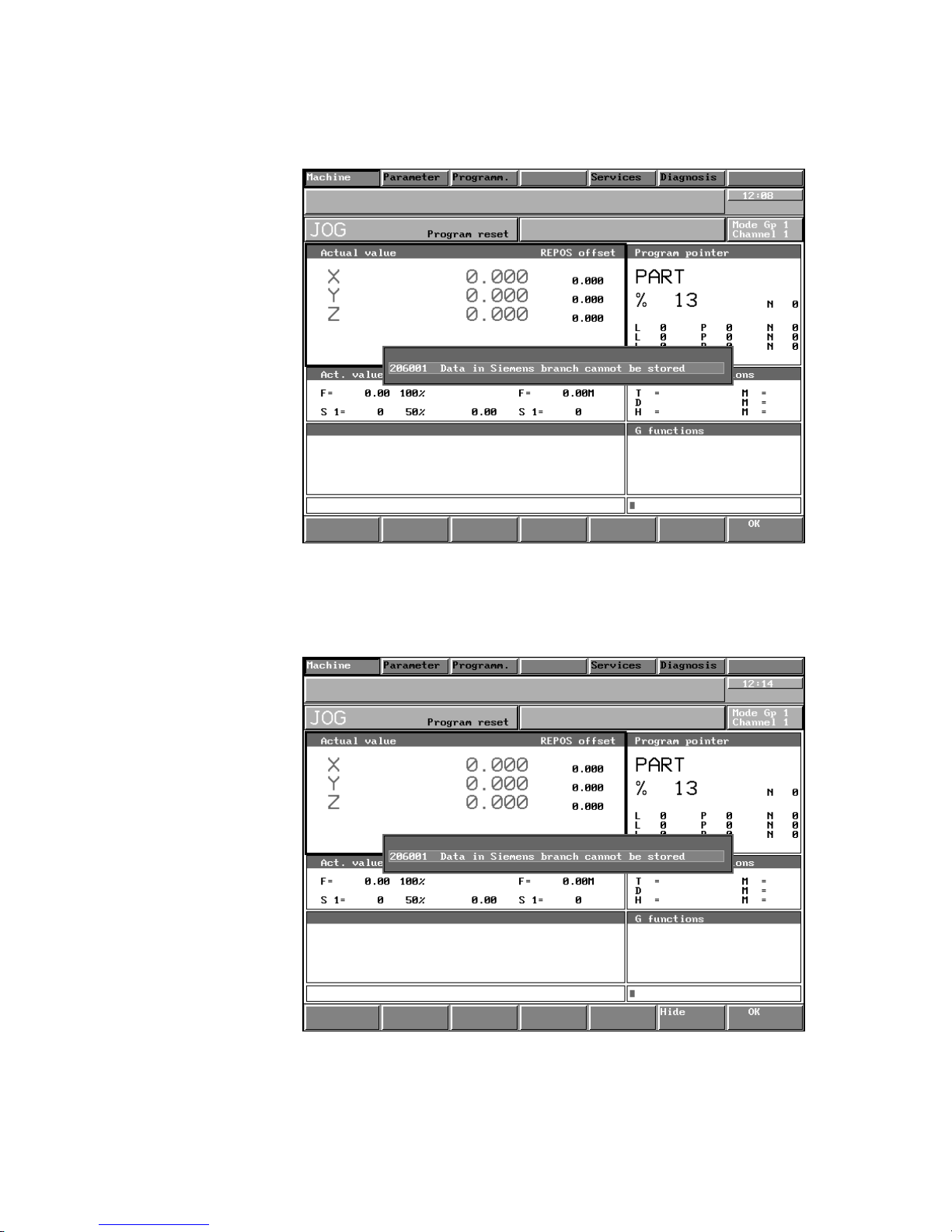
There are 3 types of dialog box:
Dialog box with The dialog must be acknowledged from a configured application.
empty softkey bar
Fig. 1.1 Example 1 dialog box
1 Alarms
1.4 Display of the alarms as dialog box
Page 15
04/96
Siemens AG 2001 All rights reserved 6FC5198–jAB40
1–7
SINUMERIK 840C / SIMODRIVE 611–D (DA)
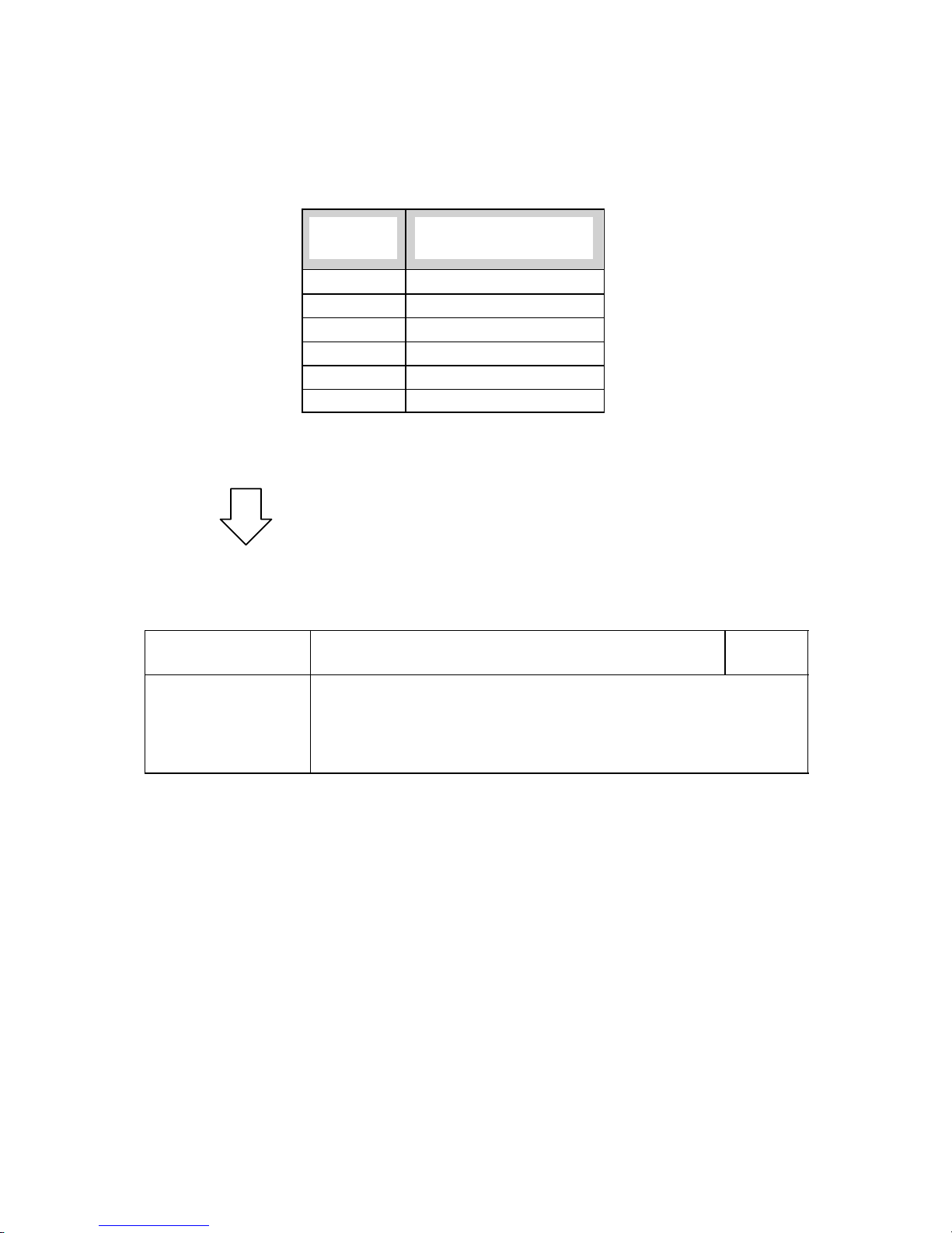
Dialog box with OK The dialog box can be acknowledged with the OK key.
softkey
Fig. 1.2 Example 2 dialog box
Dialog box with The dialog box can either be acknowledged with the OK key or it can be
OK softkey and with the HIDE softkey without being acknowledged.
HIDE softkey
Fig. 1.3 Example 3 dialog box
1 Alarms
1.4 Display of the alarms as dialog box
Page 16
04/96
Siemens AG 2001 All rights reserved 6FC5198–jAB40
1–8
SINUMERIK 840C / SIMODRIVE 611–D (DA)
1.5 Priority of alarms
Only one alarm can be displayed in the alarm line and the following priorities
apply:
Priority
range
Alarm type
0 – 100 Power on
101 – 200 Reset
201 – 300 Cancel
301 – 500 Message
301 – 500 PLC alarm
1000 Diagnosis
Within the alarm groups, the priority is in accordance with the alarm number or
priority range, i.e. the lowest alarm number/priority range has the highest priority .
The alarm priorities can be configured by the machine tool manufacturer.
An arrow on the right in the alarm line indicates that further alarms exist. These
alarms are displayed if you select the alarm overview display in the DIAGNOSIS
area.
1.5.1 Alarm description
The alarms are described in a uniform style. The column alarm heading boxes
show the alarm number, alarm text and the means of cancellation.
Alarm number Alarm text Means of
cancel.
Scan: Specifies in which state the alarm occurs.
Effect:
Specifies the sphere of influence of processing.
Explanation:
States the reasons for the alarm.
Remedy:
Instructions for eliminating the alarm state.
1 Alarms
1.5.1 Alarm description
Page 17

04/96
Siemens AG 2001 All rights reserved 6FC5198–jAB40
1–9
SINUMERIK 840C / SIMODRIVE 611–D (DA)
1 Battery: Data loss at power off! Acknowledgement key
POWER ON
Cyclic
Data is not battery-backed after power off.
During operation: Do not interrupt the production process. Data will be lost if the control is switched off.
Run-up: Data has been lost. Obligatory re-installation is activated.
Backup battery is empty.
Replace the battery when the control is switched on
If data has been lost the whole NCK/PLC unit must be re-installed.
2 Overtemperature Acknowledgement key
POWER ON
Cyclic
The second temperature monitoring threshold has been triggered because the ambient temperature is too high.
NC program is not interrupted.
Safe functioning of the hardware can no longer be guaranteed, serious damage to hardware may result.
Processing is not interrupted directly. A contact is opened on the CSB which the NC user must use to take the
appropriate measures.
A low temperature level will eliminate the error.
Switch off control (hardware damage possible).
3 Fan failure Acknowledgement key
POWER ON
Cyclic
Fan monitoring is triggered because of incorrect fan functioning.
Safe functioning of the hardware can no longer be guaranteed, serious damage to hardware may result.
Processing is not interrupted directly. A contact is opened on the CSB which the NC user must use to take the
appropriate measures.
Eliminate the fan fault, e.g. by replacing the fan.
Switch off control (hardware damage possible).
4 System of units not allowed POWER ON
S POWER ON
S After modification of NC machine data
S Interlocking of NC READY
S Interlocking of NC START
S Interlocking of Mode Group Ready
S Machining stops
An illegal combination of machine data MD 18000 display resolution and MD 5002 input resolution has been
selected. Both data must use the same system of units
For rotary axes with a position control resolution smaller than = 0.5 10–4 degrees, the function bit “High-resolution rotary axis” must be set.
Check and correct machine data combinations. Then cancel the alarm with POWER ON.
5 Power failure protection / data loss Acknowledgement key
POWER ON
The power failure protection integrated in the software could not be executed correctly because of a hardware
fault.
Data loss in the NCK unit.
Obligatory re-installation is activated.
The whole NCK unit must be re-installed.
Eliminate hardware fault.
Scan
Effect
Explanation
Remedy
Scan
Effect
Explanation
Remedy
Scan
Effect
Explanation
Remedy
Scan
Effect
Exlanation
Remedy
Scan
Effect
Explanation
Remedy
1 Alarms
1.5.1 Alarm description
Page 18

04/96
Siemens AG 2001 All rights reserved 6FC5198–jAB40
1–10
SINUMERIK 840C / SIMODRIVE 611–D (DA)
6 Start-up due to system error Acknowledgement key
POWER ON
Start-up of the control shows that a fatal error was present before reset/power off (e.g. obligatory re-installation is
activated. Alarm 5 can be set in conjunction with alarm 6. EPROM error, DRAM error, processor exceptions).
Re-installation is necessary as data loss or corruption is to be expected (no data consistency).
The NCK unit must be completely re-installed.
Cause of error can be eliminated as follows:
a) Replace hardware
b) Report the software error leading to the processor exception to the manufacturer of the control.
7 15 V undervoltage Acknowledgement key
POWER ON
Cyclic
Activates 15V voltage monitoring
Safe operation of the NC is no longer possible so NC Ready is cancelled.
Eliminate hardware fault
8 Wrong axis/spindle assignment POWER ON
S After modification of machine data
S On POWER ON
S Interlocking of NC START
S Removal of Mode Group Ready
S NC Ready relay drops out
S Machining stops
The NC machine data for axis assignment MD200* or spindle assignment MD400* have been input incorrectly or
transposed.
If error in MD 461* C axis definition:
S C axis must not be fictitious (MD 564*, bit 6)
S C axis must be defined (MD 564*, bit 7)
S Mode group numbers of C axis and spindle must be same
(MD 360*, MD 453*)
Check and correct machine data for axis and spindle assignment.
Cancel alarm with POWER ON.
9 Not enough memory for UMS POWER ON
S At POWER ON in normal mode, not in start-up mode
None
The RAM area reserved on the NC is too small for the UMS address lists for the modified system area.
Describe fewer elements (displays/texts) in modified system area (merge).
Applies up to SW 2 only
9 Overflow in altered system area POWER ON
When powering up the control
The UMS does not function
In the UMS, an altered system area has been configured that exceeds the memory area.
Configure UMS properly
Applies as from SW 4
Scan
Effect
Explanation
Remedy
Scan
Effect
Explanation
Remedy
Scan
Effect
Explanation
Remedy
Scan
Effect
Explanation
Remedy
Note
Scan
Effect
Explanation
Remedy
Note
1 Alarms
1.5.1 Alarm description
Page 19

04/96
Siemens AG 2001 All rights reserved 6FC5198–jAB40
1–11
SINUMERIK 840C / SIMODRIVE 611–D (DA)
10 UMS error POWER ON
S At POWER ON
S Interlocking of NC START
The UMS loaded in NCK has a faulty internal structure.
Reinstall UMS on hard disk.
Applies up to SW 2 only
10 Startup after software upgrade POWER ON
S At POWER ON
S The NCK–internal static memory has been deleted.
There are two causes for the alarm:
– A new NCK software version has been loaded (only when booting for the first time after software upgrade)
– The NCK–internal static RAM has failed (e.g. because of an empty back–up battery); alarm 5 is then dis-
played additionally.
The complete NCK unit must be started up again.
Applies as from SW 6
11 Undervoltage on secondary side Cancel
POWER ON
Cyclic
Short circuit on secondary side or overloading of 5V voltage
Caution: The error may have been signalled during initial start-up without the error being present (hardware wiring).
When the error occurs the shutdown routine is activated to achieve a safe state.
Restart:
Data loss has occurred, obligatory re-installation is activated
Eliminate the hardware error
Re-install
20 Cam activation wrong POWER ON
POWER ON
S Interlocking of NC start
S Interlocking of Mode Group Ready
Software cams can only be used for linear axes.
Correct the PLC user program
26 Part program block >120 char. V.24 POWER ON
S On reading data into the NC via the computer link
S Computer link transmission interrupted
S Last block declared invalid
The part program block that has been read in contains more than 120 characters. Only the characters actually
stored are counted (no spaces, no CR, etc.)
Divide the block into two or more blocks. The number of the faulty block is displayed.
Applies up to SW 2 only
Scan
Effect
Explanation
Remedy
Note
Scan
Effect
Explanation
Remedy
Note
Scan
Effect
Explanation
Remedy
Scan
Effect
Explanation
Remedy
Scan
Effect
Explanation
Remedy
Note
1 Alarms
1.5.1 Alarm description
07/97
Page 20

04/96
Siemens AG 2001 All rights reserved 6FC5198–jAB40
1–12
SINUMERIK 840C / SIMODRIVE 611–D (DA)
27 Data input disabled V.24 POWER ON
S On reading data into the NC via the computer link
No data has been read in
S The “Cycle lock” interface signal (DB 48 D0.11) is present
S An attempt has been made to read in NC machine data in normal mode
S An attempt has been made to transfer UMS data to the NC although the UMS was not enabled or not plugged
in.
S Reset DB 48 DW 0 bit 11 via PLC STATUS
S Enter new NC machine data
Applies up to SW 2 only
29 Block >254 characters V.24 POWER ON
S On reading tool data into the NC via the computer link
S Computer link transmission interrupted
S Last block declared invalid
The block read in has more than 254 characters (counting all characters read in, including blanks, CR, LF, etc.)
Divide the block into two or more blocks. The number of the faulty block is displayed.
Applies up to SW 2 only
30 Part program memory overflow V.24 POWER ON
S While reading programs in via the computer link of the NC
S Computer link transmission interrupted
S Last block declared invalid
The maximum memory space for part programs is already assigned
S Delete old programs to release memory for the reading in of new programs. The number of the faulty block is
displayed.
Applies up to SW 2 only
31 No more part program input V.24 POWER ON
S On reading in via computer link
No data has been read in
The part program memory available has been used up.
S Read and delete old part programs no longer required in order to provide more memory.
Applies up to SW 2 only
32 Data format error V.24 POWER ON
S On reading data into the NC via the computer link
S Computer link transmission interrupted
S Last block declared invalid
S The number of decades used after an address is not permissible
S The decimal point occurs in the wrong place
S Part programs or subroutines are not defined or concluded correctly (check header)
Check the program to be read in. The number of the faulty block is displayed.
Applies up to SW 2 only
Scan
Effect
Explanation
Remedy
Note
Scan
Effect
Explanation
Remedy
Note
Scan
Effect
Explanation
Remedy
Note
Scan
Effect
Explanation
Remedy
Note
Scan
Effect
Explanation
Remedy
Note
1 Alarms
1.5.1 Alarm description
Page 21

04/96
Siemens AG 2001 All rights reserved 6FC5198–jAB40
1–13
SINUMERIK 840C / SIMODRIVE 611–D (DA)
33 Programs different V.24 POWER ON
S On reading part programs into the NC memory via the computer link of the NC
No data is read in/stored
If a new program is to be read in with the same program number as one already stored in the NC, the program to
be read in is compared. If they are different, an NC alarm occurs. The point of disagreement is shown in the data
input display. The new program is not stored.
Delete the old program or rename it in the NC so that the new program can be read in.
Applies up to SW 2 only
43 PLC–CPU not ready for operation POWER ON
S Cyclic or on Restart
S Interlocking of NC START
S Interlocking of Mode Group Ready
S Interlocking of NC Ready relay
S Processing is terminated
S Hardware or software error in PLC or general data interface link
S PLC machine data error or not in agreement with user program
S Error in the PLC user program
S Selection of error fine coding
S Remove cause of error
S Check detailed error coding in PLC service menu
S Read out ISTACK
S Ascertain cause of error using the error list in the installation lists
45 Cam signal output wrong POWER ON
POWER ON
S Interlocking of NC START
S Interlocking of Mode Group Ready
Incorrect values in NC MD 310, 311
Interface output via MIXED I/O selected without the corresponding hardware
Slot in the MIXED I/O before switching on the control.
46 Invalid TO parameter number POWER ON
S After altering machine data and then formatting user memory or when powering up if MD 13 (as from SW 4
MD 60006) is not correct.
Function not usable
S Interlocking of NC START
On installation, a value greater than 32 or less than 10 has been specified for machine data 13, “Number of TO
parameters”.
“Extended tool parameter for type 50..59” deselected: 10 – 32
“Extended tool parameter for type 50..59” selected: 10 – 32
S Correct machine data
S Format user memory or, in General Reset mode, format the area for the TO data
Scan
Effect
Explanation
Remedy
Note
Scan
Effect
Explanation
Remedy
Scan
Effect
Explanation
Remedy
Scan
Effect
Explanation
Remedy
1 Alarms
1.5.1 Alarm description
Page 22

04/96
Siemens AG 2001 All rights reserved 6FC5198–jAB40
1–14
SINUMERIK 840C / SIMODRIVE 611–D (DA)
47 Wrong TO assignment lists POWER ON
S At POWER ON after modifying machine data
S Interlocking of NC START
S Value of machine data 210, “Number of TO areas”, is greater than 4
S TO start numbers in NC MD211 to 214 have not been entered in ascending order
S Input value in channel-specific NC MD 1040 to 1043 is greater than the number of TO areas under MD 210 or
is specified as 0 in the TO area
S Correct machine data
S Where appropriate format user memory if machine data were input correctly or format the TO data in General
Reset mode
S POWER ON
48 Data link to PLC not ready POWER ON
S Interlocking of NC S TART
S Interlocking of NC Ready relay
S Interlocking of Mode Group Ready
S Machining stops
During the start-up synchronization or data exchange between interface-CPU (IFC) and PLC CPU an error was
established, leading to the alarm. Data exchange between NC and PLC is still possible but the link to the programmer via the interface is not possible.
Error fine coding can give information on further error sources; in addition, check whether alarm 43 is present.
Applies up to SW 2 only
49 NC in general reset POWER ON
POWER ON
None
The software has recognized that the control is in general reset mode.
Leave general reset mode
50 Flex. memory incorrectly configured POWER ON
50 Insufficient memory for block buffer POWER ON
On pressing NC Start
Interlocking of machining
Interlocking of “NC Start”
1. The channel-specific machine data 6100* that defines the number of block buffers in a channel is not in the
permissible range.
2. No memory has been made available (MD 60014) for loading of drive software (MD 60003 or 60004).
Check and correct the values of the machine data.
Alarm Insufficient memory for block buffer (with SW 4 and higher)
Alarm Flex. memory incorrectly configured (with SW 5.4 and higher)
57 Drive link failure POWER ON
Cyclic
Interlocking of NC Ready, NC Start, Mode Group Ready, NC Stop
Internal software error or ring programming for GI or gantry axes.
S Eliminate ring programming for GI or gantry axes
S Notify service
Scan
Effect
Explanation
Remedy
Effect
Explanation
Remedy
Note
Scan
Effect
Explanation
Remedy
Scan
Effect
Explanation
Remedy
Note
Scan
Effect
Explanation
Remedy
1 Alarms
1.5.1 Alarm description
07/97
Page 23

04/96
Siemens AG 2001 All rights reserved 6FC5198–jAB40
1–15
SINUMERIK 840C / SIMODRIVE 611–D (DA)
60 Internal software error POWER ON
Cyclic
Computer stops, machining stops, interlocking of NC Start
The software has recognized an internal error but cannot rectify it.
Notify service.
67 1st computer link not ready for operation POWER ON
Cyclic or after POWER ON
Message frame transfer between host computer and NC is not possible
Host computer and NC are not synchronized owing to an incorrect input or a fault in the interface module. This
means that message frame transfer is not possible.
S Check programming of interface module
S Check machine data settings for computer link
S Check whether host computer is ready or connected
68 2nd computer link not ready for operation POWER ON
Cyclic or after POWER ON
Message frame transfer between host computer and NC is not possible
Host computer and NC are not synchronized owing to an incorrect input or a fault in the interface module. This
means that message frame transfer is not possible.
S Check programming of interface module
S Check machine data settings for computer link
S Check whether host computer is ready or connected
70 Define at least one channel POWER ON
S At POWER ON
S Interlocking of NC START
S Interlocking of Mode Group Ready
S Interlocking of NC Ready relay
S Machining not possible
At start-up, an incorrect assignment of machine data was made.
The NC will not work without channel assignment.
Check and correct machine data for channel assignment
S POWER ON
71 Too many real axes POWER ON
S At POWER ON
S Interlocking of NC START
S Interlocking of Mode Group Ready
S Interlocking of NC Ready relay
S Machining stops
S Surplus axes are not shown on the service display
More real axes than are permitted were defined in axis-specific machine data bits 564* at the time of start-up
The machine data MD 60013 (memory for real axes) is not within the permissible range or has been set too small.
Correct axis-specific machine data bits 564*.
Correct MD 60013.
Scan
Effect
Explanation
Remedy
Scan
Effect
Explanation
Remedy
Scan
Effect
Explanation
Remedy
Scan
Effect
Explanation
Remedy
Scan
Effect
Explanation
Remedy
1 Alarms
1.5.1 Alarm description
Page 24

04/96
Siemens AG 2001 All rights reserved 6FC5198–jAB40
1–16
SINUMERIK 840C / SIMODRIVE 611–D (DA)
72 Too many fictitious axes POWER ON
S At POWER ON or warm restart
S Interlocking of NC START
S Interlocking of Mode Group Ready
S Interlocking of NC Ready relay
S Machining stops
More fictitious axes than are permitted were defined in axis-specific machine data bits 564* during installation.
Correct axis-specific machine data bits 564*.
73 Axis preset in wrong mode group POWER ON
S At POWER ON or warm restart
S Interlocking of NC START
S Interlocking of Mode Group Ready
S Interlocking of NC Ready relay
S Machining not possible
At start-up, an incorrect assignment of NC machine data was made or the assignment of axis selector switch with
2 machine control panels is incorrect or a wrong axis is set in the program.
Check and correct NC machine data “Axis valid in mode group”.
S Correct program
S POWER ON
74 Too many drives POWER ON
S At POWER ON or warm restart
S Interlocking of NC START
S Interlocking of Mode Group Ready
S Interlocking of NC Ready relay
S Machining stops
S Surplus axes do not appear in the service display
The total number of spindles and real axes defined during installation is greater than permitted.
Correct axis-specific machine data bits 564* and spindle-specific machine data bits 521*.
75 Max. number of meas. circuits exceeded POWER ON
S At POWER ON or warm restart
S Interlocking of NC START
S Interlocking of Mode Group Ready
S Interlocking of NC Ready relay
S Machining stops
S Surplus axes do not appear in the service display
Output of alarm if too many axes and spindles are defined.
Reduce the number of axes (MD 564*) and spindles (MD 512*).
Axes/spindles that are not assigned to a measuring circuit are included in the number of measuring circuits.
77 Mode group no. of axis invalid POWER ON
S At POWER ON
S Interlocking of NC START
S Interlocking of Mode Group Ready
S Interlocking of NC Ready relay
S Interlocking of machining
Check and correct machine data for axis assignment and spindle assignment.
S Check and correct machine data for “Axis valid in mode group”
S Perform POWER ON
Scan
Effect
Explanation
Remedy
Scan
Effect
Explanation
Remedy
Scan
Effect
Explanation
Remedy
Scan
Effect
Explanation
Remedy
Note
Scan
Effect
Explanation
Remedy
1 Alarms
1.5.1 Alarm description
Page 25

04/96
Siemens AG 2001 All rights reserved 6FC5198–jAB40
1–17
SINUMERIK 840C / SIMODRIVE 611–D (DA)
78 Mode group no. of spindle invalid POWER ON
S At POWER ON
S Interlocking of NC START
S Interlocking of Mode Group Ready
S Interlocking of NC Ready relay
S Interlocking of machining
Check and correct machine data for axis assignment and spindle assignment.
S Check and correct machine data for “Mode group of spindle”
S Perform POWER ON
79 Mode group no. of channel invalid POWER ON
S At POWER ON
S Interlocking of NC START
S Interlocking of Mode Group Ready
S Interlocking of NC Ready relay
S Interlocking of machining
An incorrect assignment (e.g. channel gap) has been made in the channel-specific machine data for “Channel
valid in mode group”.
S Check machine data
S Perform POWER ON
80 Error in C axis definition POWER ON
S At POWER ON and warm restart
S Interlocking of NC START
S Interlocking of Mode Group Ready
S Interlocking of NC Ready relay
S Machining stops
S If C axes and spindles are incorrectly assigned, the spindle does not appear in the service display.
The C axes assigned to the spindles were either defined as non-existent or fictitious during installation, or the
spindle and assigned C axis mode groups are not identical.
Check and correct axis-specific machine data bits 564*, axis-specific machine data 360* and spindle-specific machine data 453* and 461*.
84 Coupled motion grouping defined wrong POWER ON
S At POWER ON
S At warm restart
S Interlocking of NC START
S Interlocking of Mode Group Ready
S Interlocking of machining
An illegal coupled axis grouping has been set for the assignment of coupled axes in machine data, e.g.:
S The axes do not belong to the same mode group
S The axes have different position control resolutions
S The axes are of different types (linear axis/rotary axis)
S The axes are declared as being not present
S The axes are fictitious
S The leading axis is defined as a coupled axis
Correct machine data using the “Coupled motion” function and perform a warm restart (see Start-up Guide).
Scan
Effect
Explanation
Remedy
Scan
Effect
Explanation
Remedy
Scan
Effect
Explanation
Remedy
Scan
Effect
Explanation
Remedy
1 Alarms
1.5.1 Alarm description
Page 26

04/96
Siemens AG 2001 All rights reserved 6FC5198–jAB40
1–18
SINUMERIK 840C / SIMODRIVE 611–D (DA)
85 Coupled-motion combination wrong POWER ON
S POWER ON
S Warm restart
S Interlocking of NC START
S Interlocking of Mode Group Ready
S Interlocking of machining
An undefined combination has been input in NC machine data for the coupled axis combination.
Correct machine data and perform a warm restart (see Start-up Guide).
87 Illegal software limit switch POWER ON
S After altering machine data
S Interlocking of NC START
S Interlocking of Mode Group Ready
S Interlocking of machining
An excessively large value has been entered in the NC machine data for the software limit switch. The maximum
traversing range of the individual axes results from the axis-specific position control resolution set and the input
resolution. With alarm 87, the control has automatically entered the maximum permissible value in the appropriate
NC machine data.
Check machine data for software limit switch and where appropriate correct.
Applies up to SW 2 only
88 Interpolation greater than 3D POWER ON
S When executing part programs in AUTOMATIC or MDA
S Interlocking of NC START
S Interlocking of machining
More than 3 axes have been programmed in one block in the part program block of the NC, or the “5D” function is
not active.
S Modify part program
S Do not execute more than 2 programs at once
89 More than two 3D interpolations POWER ON
S When executing part program blocks in AUTOMATIC or MDA
S Interlocking of NC START
S Machining stops
More than 3 axes have been programmed in more than 2 channels in the NC in one program block in each case.
S Modify program
S Do not execute more than 2 programs at once
90 Customer UMS invalid POWER ON
S At POWER ON when UMS bit is set
Interlocking of NC START until alarm is acknowledged.
Standard UMS is loaded.
Customer UMS faulty or >512 KB.
Check customer UMS.
Applies up to SW 2 only
91 ID no. in UMS header faulty POWER ON
S At POWER ON and with activated UMS data
Interlocking of NC START until alarm is acknowledged.
The programmed ID number in the UMS header, which is evaluated by the system software, is incorrect or has
been read incorrectly because the UMS submodules were plugged in incorrectly.
Check WS 800A software version.
Applies up to SW 3 only
Scan
Effect
Explanation
Remedy
Scan
Effect
Explanation
Remedy
Note
Scan
Effect
Explanation
Remedy
Scan
Effect
Explanation
Remedy
Scan
Effect
Explanation
Remedy
Note
Scan
Effect
Explanation
Remedy
Note
1 Alarms
1.5.1 Alarm description
Page 27

04/96
Siemens AG 2001 All rights reserved 6FC5198–jAB40
1–19
SINUMERIK 840C / SIMODRIVE 611–D (DA)
91 UMS invalid POWER ON
At POWER ON and activated UMS data
Interlocking of NC START until alarm is acknowledged.
The configured identifying number in the UMS header, evaluated by the system software, is incorrect or no UMS
has been loaded because the memory reserved for this (MD 60000) is smaller than the UMS to be loaded.
Check MD 60000 or install the correct UMS.
Applies as from SW 4
93 Wrong UMS selector POWER ON
S At POWER ON and with activated UMS data
S Interlocking of NC START until alarm is acknowledged.
The address lists preset by the NC workstation do not contain the set selectors required for error-free processing
of a UMS.
Check the system software of the NC workstation, or have it checked.
94 Wrong UMS identifier POWER ON
S At POWER ON and with activated UMS data
S Interlocking of NC START until alarm is acknowledged.
An incorrect identifier is programmed in the UMS.
Check UMS and NC workstation software.
95 Wrong number in GSB POWER ON
S At POWER ON and with activated UMS data
S Interlocking of NC START until alarm is acknowledged.
Numbers have been used in the modified system area (GSB) which are outside the reserved areas.
Check the numbers used in the modified system area.
96 Language in UMS not available Acknowledgement key
At UMS analysis (POWER ON of control not during start-up)
UMS is connected in its basic language
Two-language UMS does not contain the language activated in the control
Put correct UMS in control
Applies up to SW 1 only
101 Prewarning replace battery Acknowledgement key
POWER ON
Cyclic
Battery monitoring is activated if battery voltage falls below the advance warning voltage threshold.
The working process is not interrupted
User is advised to replace the backup battery to avoid the risk of data loss – see alarm 1.
Replace battery when control is switched on
Scan
Effect
Explanation
Remedy
Note
Scan
Effect
Explanation
Remedy
Scan
Effect
Explanation
Remedy
Scan
Effect
Explanation
Remedy
Scan
Effect
Explanation
Remedy
Note
Scan
Effect
Explanation
Remedy
1 Alarms
1.5.1 Alarm description
Page 28

04/96
Siemens AG 2001 All rights reserved 6FC5198–jAB40
1–20
SINUMERIK 840C / SIMODRIVE 611–D (DA)
102 Prewarning overtemperature Acknowledgement key
POWER ON
Cyclic
The first temperature monitoring threshold on the CBS module is activated because the ambient temperature is too
high
User is given advance warning.
The working process is not interrupted.
A lower temperature level is required to eliminate the fault
103 Initializing error NCK FB POWER ON
When powering up the control
Interlocking of NC START
Follow–up mode
Removal of Mode Group Ready
The initialization routine of the NCK FB has returned a value which is not equal to zero. The return value is output
in the alarm as block number N.
Check the NCK FB.
The alarm is initiated when powering up the control. No program can be started. Acknowledge alarm by
POWER ON.
S Alarm 103 is output only if appropriately configured by the machine manufacturer. An error has occurred in the
safety NCK–FB. For more information and remedy, refer to the manufacturer’s documentation.Applies as from
SW 5.4.
S Applies as from SW 5.4.
104 Error in machine data
When powering up the control
After a warm start
After changing a machine data
Interlocking of NC START
Follow–up mode
Removal of Mode Group Ready
A machine data contains an implausible value. The machine data error is output in the alarm as block number N.
Evaluate the block number and correct the corresponding machine data.
The alarm is initiated when powering up the control. No program can be started. Acknowledge alarm by
POWER ON.
Applies as from SW 5.4
105 Error in NCK FB
During cyclic operation of control
Interlocking of NC START
Follow–up mode
Removal of Mode Group Ready
Interruption of machining
The cyclic routines of the NCK FB have returned a value which is not equal to zero.
Evaluate the block number and check the NCK FB.
No program can be started. Acknowledge alarm by POWER ON.
S Alarm 105 is output only if appropriately configured by the machine manufacturer. An error has occured in the
safety NCK–FB. For more information and remedy, refer to the manufacturer’s documentation.
S Applies as from SW 5.4
Scan
Effect
Explanation
Remedy
Scan
Effect
Explanation
Remedy
Continuation:
Note
Scan
Effect
Explanation
Remedy
Continuation
Note
Scan
Effect
Explanation
Remedy
Continuation
Note
1 Alarms
1.5.1 Alarm description
Page 29

04/96
Siemens AG 2001 All rights reserved 6FC5198–jAB40
1–21
SINUMERIK 840C / SIMODRIVE 611–D (DA)
110 Checksum error safe monitorings POWER ON
When powering up the control
Interlocking of NC START
The MDs for the safety system are protected by a checksum after acceptance of the control. The alarm indicates
that the current checksum no longer matches the stored checksum, i.e. either an MD value has been changed
without authorization or a data is defective.
Check the MDs. Inspect the safety functions again. Have the checksum calculated again.
The alarm is initiated when powering up the control. No program can be started. Alarm acknowledgement only
possible by POWER ON.
Applies as from SW 5.4
111 Error in collision monitoring data POWER ON
At POWER ON
Block number (4–digit) Nxxss:
3rd and 4th digit: Number of protection zone 00–09 = Protection zone 1–20
1st and 2nd digit: Error identifier (see explanation)
Nibble 3,4=Error identifier:
01=Motion axis does not exist
02=Motion axes not in same mode group
03=Error in monitoring relation
04=Protection zone dimensions not available (all dimensions=0)
05=Negative protection zone dimension
06=Protection zones not defined in same plane
Machining standstill;
interlocking of machining (NC Start);
BAG–BB=0; NC–Ready=0
Error identifiers
01=Motion axis does not exist
A non–existing axis has been specified in the machine data 3800*, 3802*, 3804*.
02=Motion axes not in same mode group
Axes that are not in same mode group have been specified In the machine data 3800*, 3802*, 3804*.
03=Error in monitoring reference
The mutual deselection of the protection zone monitoring in the MD bits 38803+s*3 has not been executed correctly.
Deselection of monitoring of protection zone 2 in the machine data of protection zone 1 causes the deselection of
monitoring of protection zone 1 in the machine data of protection zone 2, i.e. deselection must always be carried
out mutually.
04=Protection zone dimensions not available
The protection zone dimensions specified in the machine data 3812*, 3814*, 3816* are all=0.
05=Negative protection zone dimension
At least one of the protection zone dimensions specified in the machine data 3812*, 3814*, 3816* is negative. But
only positive dimensions are allowed.
06=Protection zones not defined in same plane
The protection zone specified is 2–dimensional. It is related to another 2–dimensional protection zone, which is
defined in another plane. But 2–dimensional protection zones that are in a monitoring relation must lie in the same
plane.
1st possibility:
The plane of the protection zone defined in the machine data 3812*, 3814*, 3816* is not identical with the planes of
the other protection zones to be monitored.
2nd possibility:
The protection zone should not monitor the protection zones in other planes, i.e. the protection zone relation must
be corrected in the machine data bits 38803 – 38815 (monitoring relation).
Correct machine data and execute POWER ON.
Applies as from SW 6
Scan
Effect
Explanation
Remedy
Continuation
Note
Scan
Parameters:
Effect
Explanation
Remedy
Note
1 Alarms
1.5.1 Alarm description
07/97
Page 30

04/96
Siemens AG 2001 All rights reserved 6FC5198–jAB40
1–22
SINUMERIK 840C / SIMODRIVE 611–D (DA)
100* Leadscr. err. comp.-illegal grid spacg. POWER ON
S After POWER ON
S Interlocking of NC START
S Interlocking of Mode Group Ready
Leadscrew error compensation with rotary axes in NC machine data “Distance between 2 values” has been
entered for the appropriate axis with a value which cannot be divided into 360 degrees to give an integer, i.e. grid
spacing is not equal; e.g.
S Correct: NC–MD= 10 (rotary axis)
S Results in: 360/10 = 36 grid points
S Incorrect: NC–MD= 1 1
S Would give: 360/11 = 32,7 grid points
The compensation value chosen is too large compared with the distance between two leadscrew error compensation points (valid for rotary and linear axes).
Modify NC machine data “Distance between 2 values” – check NC MD 324* and 328*.
S The compensation value in NC MD 328* must be less than NC MD 324*.
104* Speed setpoint value warning limit responded Reset key
S Cyclic
S Interlocking of NC S TART
For analog measuring circuit:
The DAC set value entered is higher than in NC machine data 268* “Maximum setpoint speed (DAC)”. It is not
possible to increase the set value further.
S Traverse more slowly
S Check actual values (encoder)
S Check NC machine data “Maximum setpoint speed (DAC)”
S Check the drive actuator
112* Zero-speed control Reset key
S When accelerating
S When stopped
S When clamping
S When decelerating (delay)
S Interlocking of NC START
S Interlocking of Mode group READY
S Setpoint 0
S The control enable is removed after the time stored in NC machine data “Control enable cutout delay” has
elapsed
S Follow-up operation
S The following error could not be cleared faster than the time entered in NC machine data “Control enable
cutout delay” during positioning
S On clamping, the limit defined in NC machine data “Zero speed monitoring” was exceeded
S A mechanically clamped axis has been pushed out of position
S Fault in the control device (actuator), at the tacho, at the motor, in the CNC measuring circuit hardware or
at/on the pulse encoder
S Incorrect specification on assigning the set value output
S At start-up: wrong position control direction
S NC machine data “Zero speed monitoring” must be greater than “Coarse exact positioning limit”
S NC machine data “Control enable cutout delay” must be large enough for the following error to be removed
within this time (only applies if NC machine data “Zero speed monitoring delay” = 0)
S NC machine data “Zero speed monitoring delay” must be large enough for the following error of the individual
axis to be removed within the time entered
S Check actual values (encoder) and position control direction
Scan
Effect
Explanation
Remedy
Scan
Effect
Explanation
Remedy
Scan
Effect
Explanation
Remedy
1 Alarms
1.5.1 Alarm description
Page 31

04/96
Siemens AG 2001 All rights reserved 6FC5198–jAB40
1–23
SINUMERIK 840C / SIMODRIVE 611–D (DA)
116* Contour monitoring Reset key
In all modes
S When decelerating
S When accelerating
S At velocities greater than in NC machine data “Contour threshold speed”
S Interlocking of NC START
S Interlocking of Mode Group Ready
S Setpoint 0
S The control enable is removed after the time stored in NC machine data “Control enable cutout delay” has
elapsed
S Follow-up operation
S At a velocity greater than in NC machine data “Contour threshold speed”, the NC machine data
“Tolerance band contour monitoring” was exceeded
S When accelerating or decelerating the axis has not reached the new speed within the time defined by the K
V
factor
S Increase NC machine data “Tolerance band contour monitoring”
S Check K
V
(servo gain) factor
S Check the optimization of the speed controller
S Check the actual values (pulse encoder)
S Check the free movement of the axes
S Reduce acceleration
120* Axis specification illegal Reset key
S At POWER ON
S Axis is not processed
S Controller disable for the relevant axis
S Mode Group Ready removed
S Interlocking of NC START
S Specification of MD200x or MD384x in the relevant axis missing.
Example: MD2000 = 01020101 and MD384 = 00000000
S Specification of module number in MD200x or MD384 is greater than the number of measuring circuit modules
present.
Example: MD2000 = 04010000 and 3 measuring circuit modules are plugged in.
S Specification of the connection number in MD200x or MD384 is greater than the number of connections on the
relevant module.
Example: MD3840 = 02070000; the 2nd measuring circuit module is a SPC module and therefore has only 6
connections.
S Connection number for an input is assigned to an output and vice versa.
Example: MD3840 = 01030000; the 1st measuring circuit module is a HMS module and connection number 3
there is an input connection.
S Input or output assignment is not compatible with the plug-in submodule.
Example: MD2000 = 01040101; the 1st measuring circuit module is a HMS module with output submodule
Servo-Command 6FX1132–5BAxx on its submodule slot 1.
S Check and correct MD200x and MD384x of the relevant axis. Both these machine data must be
specified or must be zero. In addition, they must agree with the hardware configuration.
Applies up to SW 2 only
128* Measuring circuit not available POWER ON
S At POWER ON
S Axis is not processed
S Control disable for the axis concerned
S NC Ready 2 removed
S Interlocking of NC START
S Interlocking of Mode Group Ready
S Interlocking of NC RDY relay
S MD200x or MD384x indicates an empty slot on a measuring circuit module containing submodules.
Example: MD3840 = 01090000; the 1st measuring circuit module is a HMS module with submodule slot 2
empty.
S Measuring circuit module removed or defective.
S Compare and correct MD200x or MD384x with hardware configuration.
Scan
Effect
Explanation
Remedy
Scan
Effect
Explanation
Remedy
Note
Scan:
Effect
Explanation
Remedy
1 Alarms
1.5.1 Alarm description
Page 32

04/96
Siemens AG 2001 All rights reserved 6FC5198–jAB40
1–24
SINUMERIK 840C / SIMODRIVE 611–D (DA)
132* Closed-loop system hardware axis POWER ON
S Cyclic
S Interlocking of NC S TART
S Interlocking of Mode Group Ready
S Setpoint = 0
S The control enable is removed after the time stored in NC machine data “Control enable cutout delay” has
elapsed
S Follow-up operation
The measuring circuit difference signals.
S Are not in phase
S Have a fault to earth
S Are completely missing
S Check whether the measuring circuit connector has been plugged in
S By plugging in the measuring circuit short-circuit connector it is possible to check whether the measuring cir-
cuit group is in working order
S Check the difference signals using an oscilloscope
S Replace the encoders
S Check NC MD 200*, 384*
The alarm can only be cancelled by POWER ON.
136* Contamination measuring system axis POWER ON
S Cyclic
S Interlocking of NC S TART
S Interlocking of Mode Group Ready
S Machining stops
S On measuring systems with a contamination signal (e.g. EXE) an error is sent to the NC from the measuring
system.
Check the measuring system in accordance with the manufacturer’s instructions.
140* Pulse code monitoring Reset key
S Cyclic
S Interlocking of Mode Group Ready
S Interlocking of NC START
S Alarm leads to machining stop
S Transmission errors or noise from encoder
S Check encoder, cable, connector
144* Zero mark monitoring responded Reset key
S Cyclic
S Interlocking of NC S TART
Transmission errors, noise or excessive speed have caused pulses to be lost relating to an encoder revolution
S Check encoder pulses
S Check transmission path
S Switch off monitoring system briefly with MD 1820* bit 1=0
148* SW limit switch plus Reset key
S With each axis movement
S Machining stops
S Interlocking of NC START
S The software limit switch only becomes active after approach to reference point.
S Depending on the PLC interface signal “Second software limit switch active”, the first or the second limit switch
has been approached.
S Traverse away from the limit switch in the opposite direction in JOG mode.
S Check the values in machine data for software limit switches.
Scan
Effect
Explanation
Remedy
Scan
Effect
Explanation
Remedy
Scan
Effect
Explanation
Remedy
Scan
Effect
Explanation
Remedy
Scan
Effect
Explanation
Remedy
1 Alarms
1.5.1 Alarm description
Page 33

04/96
Siemens AG 2001 All rights reserved 6FC5198–jAB40
1–25
SINUMERIK 840C / SIMODRIVE 611–D (DA)
152* SW limit switch minus Reset key
S On each axis movement
S Machining stops
S Interlocking of “NC START”
S The software limit switch becomes active only after reference point approach has taken place.
S The first or second software limit switch has been approached, according to the PLC interface signal “Second
software limit switch active”.
S Travel away from the software limit switch in the opposite direction using JOG mode.
S Check NC machine data for 1st software limit switch minus or 2nd software limit switch minus.
156* Speed set val. alarm limit responded Reset key
Cyclic
S Interlocking of NC S TART
S Interlocking of Mode Group Ready
S Setpoint 0
S The control enable is removed after the time stored in NC machine data “Control enable cutout delay” has
elapsed
S Follow-up operation
S A higher set speed value has been output within the control than set in NC machine data “Threshold for drive
errors”.
S The motor could not follow the setting of the speed set value.
S On installation: wrong position control direction
S Check whether the value in NC machine data “Threshold for drive errors” is greater than the value in NC ma-
chine data “Max. speed setpoint (DAC)”
S Check the drive
S Check the position control direction
S Check the speed set value cable
S Check actual values (encoder)
160* Drift too high Reset key
Where there is semi-automatic drift compensation and changes to MDs
S Interlocking of NC START
S “Position not yet reached” is displayed
S No traversing movement is possible
S The drift to be compensated by the NC automatically has risen beyond approximately 500 mV.
S Carry out drift compensation in NC machine data “Drift compensation”
S Check whether the drift on the drive unit has been set correctly
164* Coupled-motion axis programmed Reset key
When executing a part program
S Machining is interrupted
S Interlocking of NC START
The axis-specific alarm appears if a coupled axis is assigned several times in one part program block or if an axis
is “Leading axis” and coupled axis at the same time in one part program block.
S Check and correct program
168* Servo enable traversing axis Reset key
With each axis movement
S Interlocking of NC START
S Interlocking of Mode Group Ready
S Setpoint 0
S The control enable is removed after the time stored in NC machine data “Control enable cutout delay” has
elapsed
S Follow-up operation
The axis-specific controller enable has been removed by the PLC during a traversing movement.
S Check the PLC program
Scan
Effect
Explanation
Remedy
Scan
Effect
Explanation
Remedy
Scan
Effect
Explanation
Remedy
Scan
Effect
Explanation
Remedy
Scan
Effect
Explanation
Remedy
1 Alarms
1.5.1 Alarm description
07/97
Page 34

04/96
Siemens AG 2001 All rights reserved 6FC5198–jAB40
1–26
SINUMERIK 840C / SIMODRIVE 611–D (DA)
172* Working area limitation plus Reset key
When executing a part program
S Interlocking of NC START
S Machining stops
The working area limitation specified in the setting data has been reached.
S Check the working area limitation in the setting data
S Check the program
S Program G26 with different values
176* Working area limitation minus Reset key
When executing a part program
S Machining stops
S Interlocking of NC START
The working area limitation minus preset in the setting data of the NC has been reached.
S Check the working area limitation in the setting data
S Check the machining program
S Program G25 with different values
180* Axis active in several channels Reset key
When executing a part program
S Interlocking of NC START
S Machining stops
When executing two or more programs in different channels at the same time, one axis has been programmed in
both programs (channels).
S Check both programs
S Insert L999 or @714
S Stop a channel by pressing NC STOP
Channel-specific
188* HW limit switch plus Reset key
Cyclic
S Interlocking of NC S TART
S Direction key in the direction of approach disabled
S Machining stops
The limit switch is approached in the plus direction or triggered by other errors.
S Travel away in the opposite direction
S Check PLC user program
S Check limit switches
192* HW limit switch minus Reset key
Cyclic
S Machining stops
S Interlocking of NC START
S Direction key disabled in approach direction
The machine limit switch in the minus direction has been approached or has been activated by other errors.
S Travel away in the opposite direction in JOG mode
S Check limit switches
S Check PLC user program
Scan
Effect
Explanation
Remedy
Scan
Effect
Explanation
Remedy
Scan
Effect
Explanation
Remedy
Note
Scan
Effect
Explanation
Remedy
Scan
Effect
Explanation
Remedy
1 Alarms
1.5.1 Alarm description
07/97
Page 35

04/96
Siemens AG 2001 All rights reserved 6FC5198–jAB40
1–27
SINUMERIK 840C / SIMODRIVE 611–D (DA)
196* Coupled-motion axis assigned twice Reset key
When executing a part program
S Interlocking of NC START
S Machining is interrupted
S 2 leading axes have been programmed whose coupled axes are the same.
Axis X → Axis Y
Axis Z → Axis Y
S 2 leading axes have been programmed with one leading axis also being the coupled axis of the other leading
axis.
Axis X → Axis Y
Axis Y → Axis Z
S Correct program
2000 Emergency Stop POWER ON
Cyclic
S Interlocking of NC S TART
S Setpoint 0
S Follow-up operation as internal setting
The “EMERGENCY STOP” signal is output to the NC from the PLC.
S Check with PLC STATUS
S Check whether “EMERGENCY STOP” cam has been approached or “EMERGENCY STOP” button has been
actuated
S Check the PLC user program
On selecting Start-up mode, there is always an Emergency Stop message.
2021 Contour violation with tool radius compensation Reset key
When executing a part program, with active TRC
Not: in the selection block
in the deselection block
The tool radius compensation has recognized a contour violation. Processing of the part program is interrupted
(depending on MD 5024, bit 0), the alarm is cancelled with RESET.
– The contour calculation results in a traversing movement which is opposite to the programmed movement
(e.g. when machining an internal circle, where the milling radius is larger than the circle radius).
– Between two blocks in the TRC plane, too many blocks have been programmed outside the TRC plane (see
also Programming Guide, Section 11.11). In this case, the block number displayed indicates the 4th block
outside the TRC plane.
– If the path to be traversed with perpendicular external contours is smaller than the active tool radius and G450
is programmed (TRC with transition circle).
S Check program specifications
S Deselect compensation at the respective point and select it again
S Check used tool against the specifications (tool radius too large?)
S G451, program TRC with intersection.
S Alarm is displayed with reference to block and channel.
2022 Plane not defined for TO type Reset key
When executing a part program
S Interlocking of NC START
S Machining stops
On selecting a D No. of tool type 50..59, the CRC plane and the length compensations were not defined with G16.
Define CRC plane and length compensations with G16!
Applies as from SW 4
Alarm is displayed with reference to block and channel
Scan
Effect
Explanation
Remedy
Scan
Effect
Explanation
Remedy
Note
Scan
Effect
Explanation
Remedy
Note
Scan
Effect
Explanation
Remedy
Note
Note
1 Alarms
1.5.1 Alarm description
01/99
Page 36

04/96
Siemens AG 2001 All rights reserved 6FC5198–jAB40
1–28
SINUMERIK 840C / SIMODRIVE 611–D (DA)
2023 Invalid type of tool Reset key
When executing a part program
S Interlocking of NC START
A tool has been selected with unknown tool type (0, >59), or a tool of type 50..59 has been selected, even though
the tool offset memory has been formatted with fewer than 12 parameters.
Enter a permissible tool type for the selected tool.
Applies as from SW 4
Alarm is displayed with reference to block and channel
2031 Weighting factor too large/small Reset key
When executing a part program
S Interlocking of NC START
S Machining stops
S Deletion of part setpoint
The actual axis velocity has become so large, as a result of recalculation with the specified weighting factor, that
the maximum permissible velocity with the axis-specific position control resolution set has been exceeded.
S Check NC machine data “Weighting factor” (MD 388*)
S Program a lower velocity
S Reduce the feedrate or rapid override
2036 G35 pitch decrease too high Reset key
When thread cutting
S Interlocking of NC START
S Machining stops
The lead decrease in the thread is so large that a lead greater than or equal to 0 would result at the end of the
thread.
S Program a smaller lead decrease or a shorter thread
Channel-specific
2037 Programmed S value too high Reset key
When executing a part program
None; for information only
S The programmed spindle speed in AUTOMATIC/MDA is too high.
S Resulting velocity too high for thread, see Installation and Start–up Guide, Section 10.2.
S Program lower spindle speed
2038 Path feed too great Reset key
When executing a part program
S Machining is interrupted
S Interlocking of NC START
S Axes go into follow-up mode, servo-enable is cancelled
The axis velocity has been made so large by the programmed path feedrate that the maximum permissible axis
velocity with the position control resolution set has been exceeded.
The entered acceleration data are too small.
S Program a smaller path feedrate
S Check interpolation combinations in the part program block
Channel-specific
Scan
Effect
Explanation
Remedy
Note
Note
Scan
Effect
Explanation
Remedy
Scan
Effect
Explanation
Remedy
Note
Scan
Effect
Explanation
Remedy
Scan
Effect
Explanation
Remedy
Note
1 Alarms
1.5.1 Alarm description
01/99
Page 37

04/96
Siemens AG 2001 All rights reserved 6FC5198–jAB40
1–29
SINUMERIK 840C / SIMODRIVE 611–D (DA)
2039 Reference point not reached Acknowledgement key
When executing a part program
S Interlocking of “NC START”
The reference point has not been approached by at least one axis and NC START has been pressed in MDA or
AUTOMATIC mode.
Nockensignale wurden aktiviert, ohne daß für diese ”Referenzpunkt erreicht” war .
S Approach reference point
S The alarm does not occur if the NC machine data “NC START without reference point” is set
2040 Program disabled Reset key
When executing a part program
S Machining stop
The program (MPF, SPF) called has not been enabled for processing.
Enable
Alarm is displayed with reference to channel
2041 Program does not exist in memory Reset key
When specifying a program number and then pressing NC START
S Interlocking of NC START
S Machining stops
S The preselected program is not in the memory
S A non-existent subroutine is called in the main program
S The contour for the stock removal cycle does not exist
S Select “Overview”
S Check prgram
Channel-specific
2042 Parity error in memory Reset key
When executing a part program
S Interlocking of NC START
S Machining stops
One or more characters in the memory have been corrupted so that they can no longer be recognized
S These characters are displayed in the “Correction block” or in the part program under “Programming” as “?”
S Clear part program block and re-enter
Channel-specific
2043 Program error in transformation Reset key
When executing a part program
S Interlocking of NC START
S Machining is interrupted
S Programming actual axes with transformation selected
S Programming fictitious axes with transformation deselected
S Selecting transformation although transformation has already been selected
S Programming traversing movements in the selection block of transformation
S Correct program
Channel-specific
Scan
Effect
Explanation
Remedy
Scan
Effect
Explanation
Remedy
Note
Scan
Effect
Explanation
Remedy
Note
Scan
Effect
Explanation
Remedy
Note
Scan
Effect
Explanation
Remedy
Note
1 Alarms
1.5.1 Alarm description
07/97
Page 38

04/96
Siemens AG 2001 All rights reserved 6FC5198–jAB40
1–30
SINUMERIK 840C / SIMODRIVE 611–D (DA)
2044 Error execution external Reset key
When starting a program from external
NC START is interrupted
The alarm is displayed
S When the selected program from external is already being processed in another channel
S When an interface (file transfer) is to be addressed in several channels
S When an interface is to be addressed which is already busy
S When an interface is to be addressed while an alarm is present
S When “Location receiver” or “Logical peer receiver” are unknown at the beginning of the file transfer.
S Check machine data 130*
S Check the active interfaces
S Check machine data 5148 – 5152
2046 Block > 120 characters Reset key
When executing a part program
S Interlocking of NC START
S Machining stops
An “LF” in the memory is corrupted so that a block of more than 120 characters has resulted.
S Insert “L
F
” without deleting the whole block
Channel-specific
2047 Option not available Reset key
After presetting or programming a function which is not present
S Interlocking of NC START
S Machining stops
A function has been programmed which is not included in the function set of the control.
S Correct program
S Check NC machine data
S Have Service Dept. check function options
Channel-specific
2048 Circle end point error Reset key
When processing a circle block in AUTOMATIC or MDA
S Interlocking of NC START
S Machining stops
S The programmed circle end point is not on the circle.
S The end point is further out than the limit input in NC machine data “Circle end point monitoring”
S Correct program
Alarm is displayed with reference to block and channel
2049 Axis/spindle converter not available Reset key
After presetting or programming the axis/spindle converter function which has not been implemented
S Interlocking of NC START
S Machining stops
The axis/spindle converter function has been programmed which is not included in the function set of the control.
S Correct program
S Check NC–MD
S Have Service Dept. check function options
Alarm is displayed with reference to channel
Scan
Effect
Explanation
Remedy
Scan
Effect
Explanation
Remedy
Note
Scan
Effect
Explanation
Remedy
Note
Scan
Effect
Explanation
Remedy
Note
Scan
Effect
Explanation
Remedy
Note
1 Alarms
1.5.1 Alarm description
07/97
Page 39

04/96
Siemens AG 2001 All rights reserved 6FC5198–jAB40
1–31
SINUMERIK 840C / SIMODRIVE 611–D (DA)
2050 Rotary axis path is too small with G98 Reset key
When executing a part program
S Machining stops
S Interlocking of NC start
The traversed distance to go of the rotary axis in G98 is so small (or 0) that it is not possible to calculate a path
feedrate for the linear axes to be traversed.
Check the programmed values in the block. If the rotary axis has to traverse a distance to go, path feed (G94)
should be used in this block.
Alarm is displayed with reference to channel
2056 Travel through transformation center Reset key
When executing a part program
S Interlocking of NC START
S Machining is interrupted
With TRANSMIT transformation selected, a part program block which brings about a movement directly through
the transformation centre has been programmed.
S Check program
S Check whether the function ”Travel through transformation center” can be used.
Alarm is displayed with reference to block and channel
2057 Thread/revolutional feedrate missing Reset key
When executing a part program
S Machining is not started or is terminated
S Interlocking of NC START
S A thread has been programmed with G33, G34, G35 although this function has not been implemented in the
control.
S Revolutional feedrate G95 has been programmed
S With 840 T, the NC machine data “Revolutional feedrate” has not been set
S A program not included in the function set of the control has been programmed
S Check program
S Check NC machine data
S Have function options upgraded.
Alarm is displayed with reference to block and channel.
2058 3D interpolation missing Reset key
When executing a part program
S Machining stops
S Interlocking of NC START
More than two axes have been programmed in one block in a program, or a function has been selected which may
result in additional axes from the programming, e.g. when setting the coordinate rotation
S Check program
S Have function option retrofitted if possible
Alarm is displayed with reference to block and channel
2059 Programming error with G92 Reset key
When executing a part program
S Machining is not started or is terminated
S Interlocking of NC START
S An illegal address letter has been used
S The unit and working diameter factor is ZERO
S Check program block
S Check machine data
Alarm is displayed with reference to block and channel
Scan
Effect
Explanation
Remedy
Note
Scan
Effect
Explanation
Remedy
Note
Scan
Effect
Erläuterung
Remedy
Scan
Effect
Explanation
Remedy
Note
Scan
Effect
Explanation
Remedy
Note
1 Alarms
1.5.1 Alarm description
07/97
Page 40

04/96
Siemens AG 2001 All rights reserved 6FC5198–jAB40
1–32
SINUMERIK 840C / SIMODRIVE 611–D (DA)
2060 Programming error with TO or ZO Reset key
When executing a part program
S Machining is interrupted
S Interlocking of NC START
S Tool type is 0 (i.e. no tool)
S A tool offset number which is not present has been selected
S The values in the zero offsets or tool offsets selected are too large
S Check and correct specifications of tool offsets and zero offsets
S Check and correct program
Alarm is displayed with reference to block and channel
2061 General programming error Reset key
When executing a part program
S Machining is stopped or is not started
S Interlocking of NC START
S The programmed distance to go has exceeded the permissible distance to go. This is dependent on the input
resolution, for example.
S G63 was not programmed together with G01 (G63 has no effect with G0).
S An axis for which mirroring is active has been programmed with G220 or @736.
S A thread block has been programmed with thread lead 0 or distance to go 0.
S G02/G03 has been programmed together with G63.
S The residual path of an axis in the thread block is 0 after block search with calculation.
S Check the program part and correct the incorrect setting
S Check the input resolution selected
Alarm is displayed with reference to block and channel
2062 Feed is missing Reset key
When executing a part program
S Machining stops
S Interlocking of NC START
S Revolutional feedrate G95 greater than 50 mm/min. has been programmed
S No revolutional feedrate has been programmed
S No feedrate value (F value) has been programmed
S Feedrate is missing for soft approach and retraction
S Setting in machine data MD 280* for max. speed of an axis has been given the value 0
S Check settings in program block
S Check machine data settings
S Cancel alarm using RESET key
Alarm is displayed with reference to block and channel
2063 Thread pitch too large Reset key
When thread cutting with G33
S Machining stops
S Interlocking of NC START
S The thread lead can be specified in the program under I, J or K. The programmed set value exceeds the
permissible value depending on the preset display resolution.
S Correct program block whose block number and channel number are specified in the alarm display
S Cancel alarm using RESET
Alarm is displayed with reference to block and channel
Scan
Effect
Explanation
Remedy
Note
Scan
Effect
Explanation
Remedy
Note
Scan
Effect
Explanation
Remedy
Note
Scan
Effect
Explanation
Remedy
Note
1 Alarms
1.5.1 Alarm description
01/99
Page 41

04/96
Siemens AG 2001 All rights reserved 6FC5198–jAB40
1–33
SINUMERIK 840C / SIMODRIVE 611–D (DA)
2064 Wrong programming of rounding axis Reset key
When executing a part program
S Interlocking of NC START
S Programmed path is not exited
S Machining stops
If a rotary axis is rounded to a half or whole degree, then the control monitors whether the rounding has been
maintained for the programmed positions.
S Program correct position in the rotary axis
S Check the machine data “Whole/half degree” and “Rotary axis”
S Check whether the interface signal “Clear distance to go” has been set, in which case no automatic rounding
takes place.
In the JOG modes, the control automatically rounds to valid values. In AUTOMA TIC or MDA, the control only
monitors the programmed positions without itself carrying out rounding.
Alarm is displayed with reference to block and channel
2065 Progr. position behind SW limit switch Reset key
When executing a part program
S Interlocking of NC START
S Programmed path is not traversed
S Machining stops
The programmed end point of the block is beyond the software limit switch.
S Correct program
S Machine data “1st software limit switch plus”
S Machine data “1st software limit switch minus”
S Machine data “2nd software limit switch plus”
S Check machine data “2nd software limit switch minus” depending on the PLC interface signal “2nd software
limt switch active”
Alarm is displayed with reference to block and channel
2066 Thread increase/decrease too high Reset key
When executing a part program
S Interlocking of NC START
S Machining stops
A thread or lead increase or decrease of more than 16 mm/revolution
(0.6 inches/revolution) has been programmed.
S Program smaller lead increase/decrease
Alarm is displayed with reference to block and channel
2068 Position behind working area limitation Reset key
When executing a part program
S Interlocking of NC START
S Programmed path is not traversed
S Machining stops
The programmed end point of the block is beyond the working area limitation.
S Correct program
Alarm is displayed with reference to block and channel
Scan
Effect
Explanation
Remedy
Note
Note
Scan
Effect
Explanation
Remedy
Note
Scan
Effect
Explanation
Remedy
Note
Scan
Effect
Explanation
Remedy
Note
1 Alarms
1.5.1 Alarm description
07/97
Page 42

04/96
Siemens AG 2001 All rights reserved 6FC5198–jAB40
1–34
SINUMERIK 840C / SIMODRIVE 611–D (DA)
2069 5D tool length comp. not possible Reset key
When executing a part program
S Machining is interrupted or not performed
S Interlocking of NC START
S Cutter radius compensation has been selected
S No linear interpolation has been selected
S Function is not enabled
S Machine data have been entered incorrectly
S Export version
S Check program
S Check machine data
Alarm is displayed with reference to block and channel
2070 5D interpolation missing Reset key
When executing a part program
S Machine stops
S Interlocking of NC START
More than three axes have been programmed in one block in a program, or a function has been selected which
may result in additional axes from the programming, e.g. when specifying the coordinate rotation.
S Check program
S Have function option retrofitted if possible
Alarm is displayed with reference to block and channel
2072 Wrong input value contour definition Reset key
When working in AUTOMATIC or MDA
S Machining is not performed or is terminated
S Interlocking of NC START
When programming, an input which cannot be calculated was specified for contour definition calculation.
S Check program and correct input values
S Cancel alarm using “RESET”
Alarm is displayed with reference to block and channel
2073 No intersection contour definition Reset key
When working in AUT OMATIC
S Machining is not performed or is terminated
S Interlocking of NC START
In calculating the contour definition with the programmed values, no intersection results.
S Check program settings
S Cancel alarm using “RESET”
Alarm is displayed with reference to block and channel
2074 Wrong angle value contour definition Reset key
When working in AUTOMATIC or MDA
S Interlocking of NC START
S Machining stops
S Angle > or = 360 degrees has been programmed
S Value of angle for the contour described is meaningless
S Check and correct program settings
S Cancel alarm using “RESET”
Alarm is displayed with reference to block and channel
Scan
Effect
Explanation
Remedy
Note
Scan
Effect
Explanation
Remedy
Note
Scan
Effect
Explanation
Remedy
Note
Scan
Effect
Explanation
Remedy
Note
Scan
Effect
Explanation
Remedy
Note
1 Alarms
1.5.1 Alarm description
07/97
Page 43

04/96
Siemens AG 2001 All rights reserved 6FC5198–jAB40
1–35
SINUMERIK 840C / SIMODRIVE 611–D (DA)
2075 Wrong radius angle contour definition Reset key
When working in AUTOMATIC or MDA
S Interlocking of NC START
S Machining stops
S Radius value too large
S Radius value not permitted with the contour described
S Check program
S Cancel alarm using Reset
Alarm is displayed with reference to block and channel
2076 Wrong G02/G03 contour definition Reset key
When working in AUTOMATIC or MDA
S Interlocking of NC START
S Machining stops
Circle direction with the contour described is not possible
S Correct program
S Cancel alarm using “RESET”
Alarm is displayed with reference to block and channel
2077 Wrong block sequence contour def Reset key
When processing part programs in AUTOMATIC
S Machining is terminated
S Interlocking of NC START
In calculating the contour definition several blocks are required.
S Block sequence cannot be correct
S Inadequate information is available (under-defined)
S Check program
S Cancel alarm using Reset
Alarm is displayed with reference to block and channel
2078 Wrong input parameters contour def. Reset key
When processing part programs in AUTOMATIC or MDA
S Machining stops
S Interlocking of NC START
S Programmed parameter sequence is not permitted
S Parameter sequence is incomplete with the contour described
Example:
N10... X60 B15 LF (Z axis missing
N20... X90 B10 L
F
S Check program
S Cancel alarm using Reset
Alarm is displayed with reference to block and channel
2081 Block not allowed with TRC Reset key
When processing in AUT OMATIC
S Machining is stopped
S Interlocking of NC START
With TRC selected, the following functions may not be programmed:
G33, G34, G35, G58, G59, G92, @714 and all the functions that trigger an @714. e.g. G74, G200
S Program G40 beforehand
S Deselection of TRC with G41, G42 D00
Alarm is displayed with reference to block and channel
Scan
Effect
Explanation
Remedy
Note
Scan
Effect
Explanation
Remedy
Note
Scan
Effect
Explanation
Remedy
Note
Scan
Effect
Explanation
Remedy
Note
Scan
Effect
Explanation
Remedy
Note
1 Alarms
1.5.1 Alarm description
07/97
Page 44

04/96
Siemens AG 2001 All rights reserved 6FC5198–jAB40
1–36
SINUMERIK 840C / SIMODRIVE 611–D (DA)
2082 TRC plane cannot be defined Reset key
When processing a part program in AUTOMATIC
S Machining is stopped
S Interlocking of NC START
The axes of the TRC plane selected do not exist.
S Machine data “Abscissa for prog. G16”
S Machine data “Ordinate for prog. G16”
S Machine data “Applicate for prog. G16”
S Select correct plane using G16
Alarm is displayed with reference to block and channel
2083 Contour violation with TRC Reset key
When TRC is selected in AUT OMATIC
Not: in the selection block
in the deselection block
A contour violation may have occurred on the workpiece. The program is continued if MD 5024, bit 0, is set or
machining is aborted.
This also depends on whether the alarm has been acknowledged with the Acknowledgement key or the Reset key.
The calculated compensation results in a direction of travel that is opposite to the programmed direction.
S Check the program
S Deselect the compensation at a suitable point and reselect
Alarm is displayed with reference to block and channel
2087 Coordinate rotation/ZO not allowed Reset key
When working in AUTOMATIC or MDA
S Interlocking of NC START
S Machining is interrupted
S After selecting coordinate rotation (G54 to G59) a circular movement (G02, G03) was programmed in the follo-
wing block.
S After selecting coordinate rotation (angle ≠ 0 degrees) the settable zero offset (G54 to G57) was changed.
S After selecting coordinate rotation (angle ≠ 0 degrees) the plane (G16, G17, G18, G19) was changed.
S Correct program
S The plane can only be changed if the angle of rotation is 0 degrees.
S The settable zero offset (G54 to G57) can only be changed if the angle of rotation is 0 degrees.
S Set angle of rotation in the settable zero offsets (G54 to G57) to 0 degrees and work only with G58 and G59.
Alarm is displayed with reference to block and channel
2160 Illegal scale factor Reset key
When working in AUTOMATIC or MDA
S Interlocking of NC START
S Machining is interrupted
The scale factor has exceeded the valid range of values:
+ P is negative
+ P = 0
+ P > 99.99999
Note the valid range of values for scale factor:
(P = 0.00001 to 99.99999)
Alarm is displayed with reference to block and channel
Scan
Effect
Explanation
Remedy
Note
Scan
Effect
Explanation
Remedy
Note
Scan
Effect
Explanation
Remedy
Note
Scan
Effect
Explanation
Remedy
Note
1 Alarms
1.5.1 Alarm description
07/97
Page 45

04/96
Siemens AG 2001 All rights reserved 6FC5198–jAB40
1–37
SINUMERIK 840C / SIMODRIVE 611–D (DA)
2161 Illegal scale modification Reset key
When working in AUTOMATIC or MDA
S Interlocking of NC START
S Machining is interrupted
With a scale factor of 1, an axis position was programmed which was so large that internal representation is no
longer possible.
S Check programmed axis position
S Reduce scale factor
Alarm is displayed with reference to block and channel
2171 Approach not possible Reset key
When working in AUTOMATIC or MDA
S Machining is interrupted
In the block after approach, no axis for the selected plane (G16, G17, G18, G19) has been programmed, so that a
vector to the tangential approach cannot be calculated.
S In the selection block, or in the following block for soft approach, @714 has been programmed.
S Correct program (G147, G247, G347), programming at least one axis of the selected plane in the block after
the approach.
Alarm is displayed with reference to block and channel
2172 Retraction not possible Reset key
When working in AUTOMATIC or MDA
S Machining is interrupted
In the block before retraction no axis for the selected plane (G16, G17, G18, G19) has been programmed, so that
a vector to the tangential exit cannot be calculated.
S In the deselection block or in the previous block @714 has been programmed
S G48 programmed without previous selection
S More than 5 axes are traversed in the deselection block because 1 axis has been added to the plane.
S Correct program (G148, G248, G348, G48), programming at least one axis of the selected plane in the block
before the retraction movement.
Alarm is displayed with reference to block and channel
2173 Approach/retraction plane wrong Reset key
When executing a part program
S Machining is interrupted
S A plane change is programmed in the block after selection (G16, G17, G18, G19)
S A plane change is programmed in the deselection block
S Correct program (plane change)
Alarm is displayed with reference to block and channel
2184 M fct. for C axis switchover not allowed CANCEL
Cyclic
None
M function for C axis ON/OFF (MD 260, MD 261) has been given a value reserved by the system.
Enter the correct value
Scan
Effect
Explanation
Remedy
Note
Scan
Effect
Explanation
Remedy
Note
Scan
Effect
Explanation
Remedy
Note
Scan
Effect
Explanation
Remedy
Note
Scan
Effect
Explanation
Remedy
1 Alarms
1.5.1 Alarm description
07/97
Page 46

04/96
Siemens AG 2001 All rights reserved 6FC5198–jAB40
1–38
SINUMERIK 840C / SIMODRIVE 611–D (DA)
2189 Transformation not defined Reset key
On transformation selection
S Interlocking of NC START
S Machining stops
S The type of transformation is not defined
S The transformation axes are in different mode groups
S The option of selecting transformation is not available
S Transformation has been selected in an illegal channel
S Transformation is defined several times or wrongly
S Transformation data block has been declared invalid by alarm 3087 (error in transformation data)
S Check transformation data block
S Check program
S Order option
S Check channel number
Alarm is displayed with reference to block and channel
2190 Transformation axes assigned Reset key
On transformation selection
S Interlocking of NC START
S Machining stops
A transformation has been selected whose actual axes are also used in another channel in a parallel transformation.
S Wait until transformation is deselected in the parallel channel
S Check program
Alarm is displayed with reference to block and channel
2191 Transformation in zero Reset key
On selecting transformation in AUTOMATIC or MDA
S Interlocking of NC START
S Machining is interrupted
Transformation was selected at a time when one or more axes involved in transformation have the actual position
ZERO.
When selecting TRANSMIT, the X axis (transverse axis) must not have the actual position ZERO.
Before selecting transformation, set the actual axes of the transformation to be selected to permissible actual positions. (With TRANSMIT set the X axis to X ≠ 0)
Alarm is displayed with reference to block and channel
2192 Following error comp. not possible Reset key
At the beginning of a threading block, if the option has been selected.
Machining is stopped and NC START is interlocked
The servo gain (KV) factors of the axes involved in thread cutting are too small.
Check the servo gain factors of the axes involved in thread cutting and correct if necessary–
2193 Wrong axis/spindle operation Reset key
When switching over from C axis to spindle
S Machining stops
S Interlocking of NC START
A spindle has been programmed in C axis mode or a C axis has been programmed in spindle mode
Change C axis/spindle mode
Applies up to SW 2
Scan
Effect
Explanation
Remedy
Note
Scan
Effect
Explanation
Remedy
Note
Scan
Effect
Explanation
Remedy
Note
Scan
Effect
Explanation
Remedy
Scan
Effect
Explanation
Remedy
Note
1 Alarms
1.5.1 Alarm description
07/97
Page 47

04/96
Siemens AG 2001 All rights reserved 6FC5198–jAB40
1–39
SINUMERIK 840C / SIMODRIVE 611–D (DA)
2194 There is no FIFO Reset key
After POWER ON or warm start
S Function is not executed
S Interlocking of NC START
FIFO has been assigned to a channel but has not been activated.
S Correct program
S Check NC MD
S Have service personnel check the function option
S Have function option retrofitted
Applies up to SW 2
2195 Too many FIFO channels defined Reset key
At POWER ON or warm restart
S Interlocking of NC START
S Machining not possible
The FIFO memory can be assigned to a maximum of two channels
S Check NC MD
Applies up to SW 2
2260 Incorrect parameters “Ext. stop” Reset key
When con f i guring G421–6.
Machining stops
1. Axis/spindle already involved in extended stopping and retraction.
2. Axis/spindle already involved through G422/5/6 in extended stopping and retraction.
Check and modify programming/parameterization.
Applies as from SW 4. Alarm is displayed with reference to channel
2500 Program is being edited Acknowledgement key
At NC STAR T
S Interlocking of NC START
S Machine stops
NC START calls a program which is in the process of being edited
Terminate editing
2501 Program is being read-in Acknowledgement key
At NC STAR T
S Function is not executed
S Interlocking of NC START
NC START calls a program which is in the process of being read in through the computer link or from disk from the
MMC.
Wait for the end of the read-in process
2502 Program already exists Reset key
When starting a program from external
S NC START is interrupted
The alarm is displayed
S If a program with the same program no. as the program to be processed externally is already in the part pro-
gram memory.
S Rename or delete the program which already exists
Channel-specific
Scan
Effect
Explanation
Remedy
Note
Scan
Effect
Explanation
Remedy
Note
Scan
Effect
Explanation
Remedy
Note
Scan
Effect
Explanation
Remedy
Scan
Effect
Explanation
Remedy
Scan
Effect
Explanation
Remedy
Note
1 Alarms
1.5.1 Alarm description
07/97
Page 48

04/96
Siemens AG 2001 All rights reserved 6FC5198–jAB40
1–40
SINUMERIK 840C / SIMODRIVE 611–D (DA)
2503 Not enough memory available Reset key
When starting a program from external
S NC START is interrupted
The alarm is displayed
S When the memory set in MD30 is not available for the program to be processed externally.
S Make sufficient part program memory available (delete part programs)
S Lower value in MD30
Channel-specific
2504 Emergency retract triggered Reset key
Cyclic in the servo cycle when LINK_ON for the following axis (from servo).
Machining interrupt, interlocking of NC START; removal of Mode Group Ready.
The threshold MD “Emergency retraction threshold” programmed for monitoring of synchronism has been excee-
ded and emergency retraction triggered.
Prerequisite: Enable by means of PLC IS “Emergency retraction enabled”.
Inspect the drives; check the velocity and acceleration limit values of the following axis/spindle; check the emergency retraction threshold; check the link factors.
Applies as from SW 3. Alarm is displayed with reference to channel
2505 Error in NCK FB
During cyclic operation of control
Interlocking of NC START
Follow–up mode
Removal of Mode Group Ready
Interruption of machining
The machine data for the SGE/SGA input/output allocations (46000 – 47999) have been entered incorrectly. The
incorrect MD No. is output in the alarm as block no. Nxxxxx.
Correct the indicated machine data.
No program can be started. Acknowledge alarm by RESET.
S The alarm 2505 is only output if configured correspondingly by the machine manufacturer. An error has
ocurred in the Safety–NCK–FB. For explanation and remedy, please refer to the machine manufacturer‘s documentation.
S Applies as from SW 5.4
2506 Extended function outp. in target block
During block preprocessing in AUT OMATIC or MDA
Interlocking of NC–START
The target block during block preprocessing cannot be a G511/G522 block, as the output of accumulated miscella-
neous functions and the extended output of the G511/G522 block collide functionally.
Select another target block.
Channel–specific reset alarm (as from SW 5.4), alarm is displayed with reference to channel
Scan
Effect
Explanation
Remedy
Note
Scan
Effect
Explanation
Remedy
Note
Scan
Effect
Explanation
Remedy
Continuation
Note
Scan
Effect
Explanation
Remedy
Note
1 Alarms
1.5.1 Alarm description
07/97
Page 49
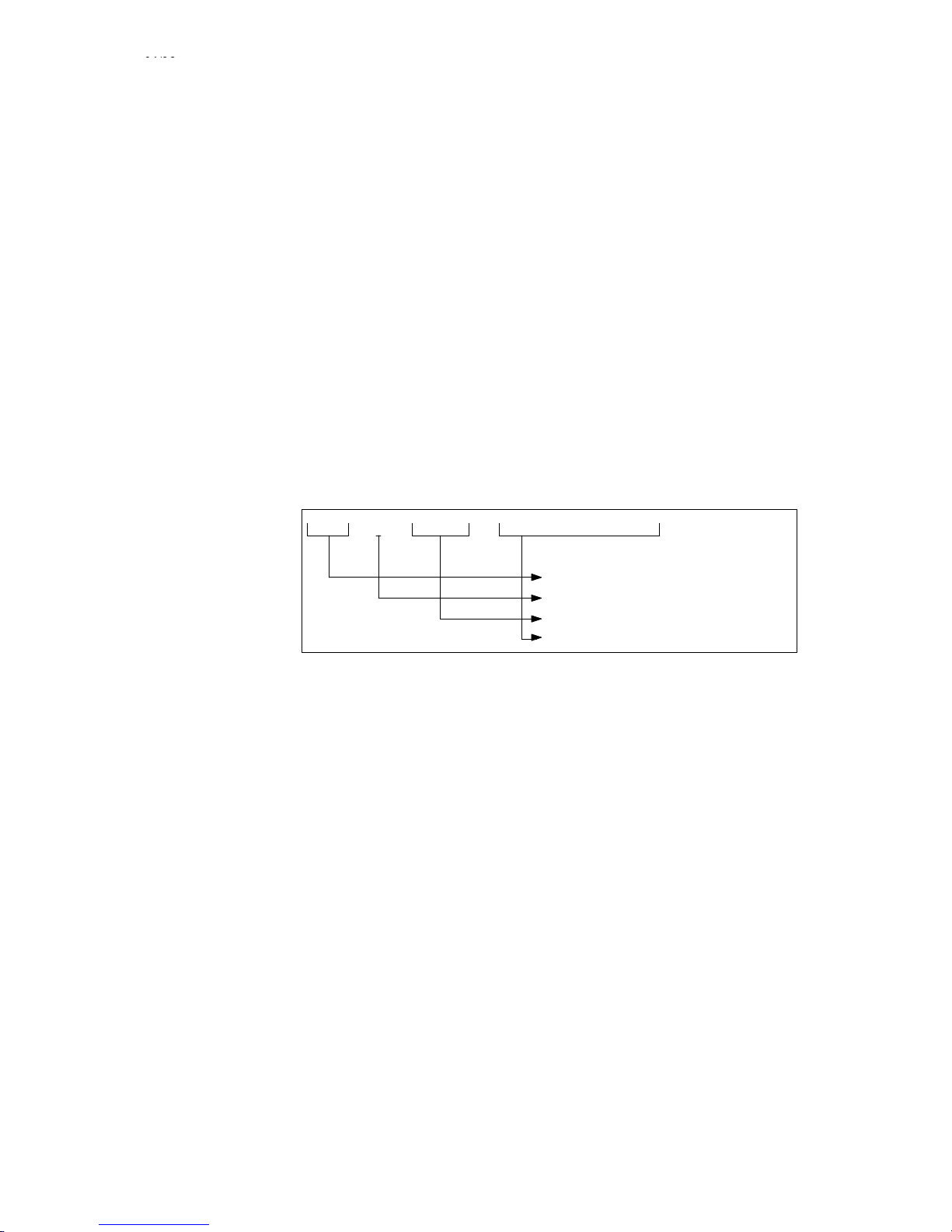
04/96
Siemens AG 2001 All rights reserved 6FC5198–jAB40
1–41
SINUMERIK 840C / SIMODRIVE 611–D (DA)
3000 General programming error Acknowledgement key
S A general programming error which cannot properly be explained has been made in one block in the program.
S Division by 0
S A G function which does not exist has been programmed
S An R parameter which does not exist has been programmed
S No +,–, /,” has been programmed in the R parameter chaining
S Range of values has been exceeded with R parameter calculation
S No M19 function allowed with active G96 ”Constant cutting rate”
S Number of decades exceeded (M, S, T, D, H, L, P, F)
S Subroutine number of passes P not programmed directly behind L
S Main block “:” programmed in subroutine
S Two decimal points programmed
S Decimal point programmed with M, S, T, D, H, L, P
S More than 8 decades programmed
S The programmed axis values exceed the travel range limits with the set input resolution
S Auxiliary functions D, F, S or T are programmed with a minus sign.
S SW 3 and higher, block search to a spline interpolation coefficient block
S The F word in G501 exceeds the value range or is negative.
S Check the incorrect block in the “Correction block” display
S The cursor is placed on the incorrect word, if possible
S The block number of the incorrect block is positioned behind the alarm number in the alarm line.
S Correct the F word accordingly.
Example:
3000 N00101
Channel number
Alarm number
Block number ”N10” which contains errors
Alarm text
General programming error
Alarm is displayed with reference to channel
Explanation
Remedy
Note
1 Alarms
1.5.1 Alarm description
09/01
Page 50

04/96
Siemens AG 2001 All rights reserved 6FC5198–jAB40
1–42
SINUMERIK 840C / SIMODRIVE 611–D (DA)
3001 Number of geometry parameters > 5 Acknowledgement key
When executing a part program
S Machining stops
S More than 2 radii or more than 2 angles have been programmed in the block
S More than 5 geometry parameters such as axes, interpolation parameters, radii, angles, etc. have been
programmed in the block
S Check the faulty block in the “Correction block” display
S If possible the cursor is positioned in front of the faulty word
S The number of the faulty block is after the alarm number in the alarm line
Example:
3000 1 N0010 General programming error
3000 – Alarm number
1 – Channel number
N0010 – Block number “N10” containing errors.
Alarm is displayed with reference to block and channel
3002 Polar coordinates/radius error Acknowledgement key
When executing a part program
S Machining stops
S Interlocking of NC START
S When programming circle/radius, full circle programmed.
S For cylindrical interpolation if:
– Calculated interpolation parameters in the C axis are too large or P factor is too small
– P factor or axial distance to go of the rotary axis for cylindrical interpolation too large
S Check the faulty block in the “Correction block” display
S If possible the cursor is positioned in front of the faulty word
S The number of the faulty block is after the alarm number in the alarm line
Scan
Effect
Explanation
Remedy
Note
Scan
Effect
Explanation
Remedy
1 Alarms
1.5.1 Alarm description
07/97
Page 51

04/96
Siemens AG 2001 All rights reserved 6FC5198–jAB40
1–43
SINUMERIK 840C / SIMODRIVE 611–D (DA)
3003 Invalid address programmed Acknowledgement key
When executing a part program
S Machining stops
An address has been programmed other than that entered in NC machine data.
The error can also occur when invalid values for G functions are entered in the channel-specific MD as from 108*
(delete position specification for G channel-specific functions).
Example:
Wrong: N20 G0 C100 L
F
(rapid traverse for fourth axis)
However , the fourth axis is defined by the address Q in the NC
machine data.
Correct: N20 G0 Q100 L
F
S Check the faulty block in the “Correction block” display
S If possible, the cursor is positioned in front of the faulty word
S The number of the faulty block is after the alarm number in the alarm line
Alarm is displayed with reference to block and channel
3004 Error in CL800 programming Acknowledgement key
Machining stops
Formal errors
S Machining stops
S Incorrectly entered characters (0...9 and a...f are possible)
S @ number is greater than the decades for a text-type message
S @ number or @ function not implemented with SINUMERIK 840
S @ number or @ function cannot be programmed in CL800 or are not defined
Input errors with address letters and numerical values
S Incorrect address letters (K, R and P are permitted)
S Number of decades too high (max. K 8 decades permitted)
S Number of decades too high (max. R 4 decades permitted)
S Number of decades too high (P 4 decades permitted)
S R parameter number not defined or too high
S Point programmed in R parameter number
S Point programmed in P parameter number
S Incorrect number of words
Input errors with specific @ functions:
Program branching
S Error in the block number (programmed point, block number greater than four decades)
Data transfer system line – R parameter
S Constant or R parameter contents programmed too large for information such as: axis number, channel
number, TO area, NC/PLC machine data, NC setting data, D number , P number, group for zero offsets, preset
“COARSE/FINE” alarm number
S Bit number too large (0 to 7 are permitted)
S System line non-existent
S Incorrect value input for system line
Mathematical and logical functions
S Value selected too high for square root
(+/– 00 000 001...99 999 999 permitted)
S Incorrect angle selected for sine (–360 (0) + 360 permitted)
S Two constants used for:
Angle from two vector components, OR, EXOR, AND, NAND
S Incorrect characters input for logical functions (0, 1 permitted)
(Only bits and bytes) (max. eight bits)
NC specific functions
S Incorrect address letter used for number of axes
S Number of axes selected too high (max. 3 axes permitted per block)
S No axis name programmed (0)
Alarm is displayed with reference to block and channel
Scan
Effect
Explanation
Remedy
Note
Effect
Explanation
Note
1 Alarms
1.5.1 Alarm description
07/97
Page 52

04/96
Siemens AG 2001 All rights reserved 6FC5198–jAB40
1–44
SINUMERIK 840C / SIMODRIVE 611–D (DA)
3005 Error in contour definition Acknowledgement key
When executing a part program
S Machining stops
The coordinates in the contour description have been defined so that there is no intersection.
S Too many geometry values have been programmed
S Check the faulty block in the “Correction block” display
S If possible the cursor is positioned in front of the faulty word
S The number of the faulty block is after the alarm number in the alarm line
Alarm is displayed with reference to block and channel
3006 Wrong block structure Acknowledgement key
When executing a part program
S Machining stops
S Interlocking of NC START
S Approach to reference point with program and specification of the wrong G function or more than one axis, or
an impermissible axis.
S Wrong thread lead parameters with G33
S More than 3 M functions in the block
S More than 1 S function in the block
S More than 1 T function in the block
S More than 1 H function in the block
S More than 4 auxiliary functions in the block
S More than 6 axes + geometry parameters
S More than 5 axes with G00, G01, G02, G03
S More than 2 axes with G10, G11, G12, G13, G110, G111, G112
S More than one radius/angle with G10, G11, G12, G13, G110, G111, G112
S Negative radius with G10, G11, G12, G13, G110, G111, G112
S First programming of polar coordinates G10, G11, G12, G13 or angle/radius
S More than two axes with G02, G03 (circle radius programming)
S G04 programmed with addresses other than X, F or S
S G04 is not programmed in the block by itself
S M19 S is programmed with other functions
S Incorrect circle parameters with G02, G03 axes
S Axis missing with circle radius programming
S Before the first G110 block in the program, a G10/G11 block must have been programmed
S G110 may not be programmed with axes
S Incorrect programming in connection with G176 freeze function
S Either too few measured value memories or none at all have been defined for G720/721/722 via the flexible
memory configuration
S On G511/G522
– An F word does not immediately follow G511/G522
– G511/G522 is superfluous, because neither a miscellaneous function nor a program coordination
command or an F word output to the PLC is programmed.
S Check the faulty block in the “Correction block” display
S If possible the cursor is positioned in front of the faulty word
S The number of the faulty block is after the alarm number in the alarm line
S Re G511/G522
– Place the F word immediately after G511/G522
– Delete G511/G522 F...
Alarm is displayed with reference to block and channel
Scan
Effect
Explanation
Remedy
Note
Scan
Effect
Explanation
Remedy
Note
1 Alarms
1.5.1 Alarm description
07/97
Page 53

04/96
Siemens AG 2001 All rights reserved 6FC5198–jAB40
1–45
SINUMERIK 840C / SIMODRIVE 611–D (DA)
3007 Error in programming setting data Acknowledgement key
When executing a part program
S Machining stops
S M19 without S word
S Spindle not present
S Illegal setting data programmed,
e.g. G92 X... Y..., G92 D, T, A, I, J
S Error in parameterization of handwheel pulse weighting for G27 (SD 564*)
S Check the faulty block in the “Correction block” display
S If possible the cursor is positioned in front of the faulty word
S The number of the faulty block is after the alarm number in the alarm line
Alarm is displayed with reference to block and channel
3008 Subroutine error Acknowledgement key
When executing a part program
S Machining stops
S M17 not in the subroutine
S M02, M30 in the subroutine
S M17 in the main program
S More than 8 subroutine levels
S Check the faulty block in the “Correction block” display
S If possible the cursor is positioned in front of the faulty word
S The number of the faulty block is after the alarm number in the alarm line
S SW 3 and higher, number of permissible subroutine levels exceeded
S Subroutine call in the block with M2, M30 or M17
S From SW 5 subroutines and main programs can be terminated with M02, M17 and M30.
Alarm is displayed with reference to block and channel
3009 Program disabled Acknowledgement key
S On NC STAR T, or when editing a program during machining
S Machining stops
S Pressing “NC START” calls a program which was disabled by being opened, by “Copy” or by “Rename”. While
a program is being edited it may not be called by “NC START”.
Once editing is complete, the locked program must be enabled.
Alarm is displayed with reference to block and channel
3010 Intersection error Acknowledgement key
S When executing a part program
S Machining stops
A mistake has been discovered during reference processing in conjunction with the calculation of intersection.
Possible causes are:
S Contour program without G00, G01, G03
S Contour program with “Empty buffer memory” (@714)
S Programmed axes are not the same as the plane selected
S No intersection found
S Stock removal path circular
S R parameter number not available
Check program in which contour is stored.
Alarm is displayed with reference to block and channel
Scan
Effect
Explanation
Remedy
Note
Scan
Effect
Explanation
Remedy
Note
Scan
Effect
Explanation
Remedy
Note
Scan
Effect
Explanation
Remedy
Note
1 Alarms
1.5.1 Alarm description
01/99
Page 54

04/96
Siemens AG 2001 All rights reserved 6FC5198–jAB40
1–46
SINUMERIK 840C / SIMODRIVE 611–D (DA)
3011 Axis twice or too many axes Acknowledgement key
S When executing a part program
S Machining stops
S An axis has been programmed twice in the same block
S More than five axes have been programmed
S Check the faulty block in the “Correction block” display
S If possible the cursor is positioned in front of the faulty word
S The number of the faulty block is after the alarm number in the alarm line
Alarm is displayed with reference to block and channel
3012 Block does not exist in memory Reset key
S On block search or jumps in the part program
S Machining stops
S Interlocking of “NC START”
S On block search, the block number is not available in the program.
S On jumping in the program, the programmed block number cannot be found.
S Program which does not conclude with M30, M17
S The alarm is displayed
– if a forward jump has been programmed outside the maximum memory area with “Execution from
external”. (The target of the jump cannot be read in to the available memory area)
– when backward jumps or jumps to the present block location have been programmed
S Check the part program as regards the correct block number target or the correct program conclusion with
M30/M02 or M17.
– Increase maximum memory for “Execution from external” (MD 30)
– Reduce jump distance
– Delete backward jumps or jumps to the present block location.
Alarm is displayed with reference to block and channel
3014 Axis disabled in channel Acknowledgement key
S When executing a part program
S Machining stops
The programmed axis is disabled for this channel by means of the NC machine data “Axis not valid for channel 1,
2, 3 or 4”.
S Observe the programming notes of the machine manufacturer.
S Correct machine data if necessary.
Alarm is displayed with reference to block and channel
3015 Main block not in memory Acknowledgement key
S On automatic block search
S Processing is not started
No main block was found in front of the target block during an automatic block search.
S Check target block
S Use another block search
Channel-specific
Applies up to SW 2 only
Scan
Effect
Explanation
Remedy
Note
Scan
Effect
Explanation
Remedy
Note
Scan
Effect
Explanation
Remedy
Note
Scan
Effect
Explanation
Remedy
Note
1 Alarms
1.5.1 Alarm description
07/97
Page 55

04/96
Siemens AG 2001 All rights reserved 6FC5198–jAB40
1–47
SINUMERIK 840C / SIMODRIVE 611–D (DA)
3016 Error in external data input Acknowledgement key
S On entering data from the PLC to the NC
S Machining stops
With external data input from PLC and NC:
S The code is incorrect
S The value is too high
S The dimension ID is not valid
S Check PLC program
3017 Part program available twice Acknowledgement key
S At POWER ON
S Machining stops
The UMS contains a part program which is already stored in the part program memory of the NC (with the same
ID).
S Delete or rename the program in the part program memory
S Use a different UMS
Applies up to SW 2 only
3018 Distance to contour too large Acknowledgement key
S With AUTO interrupt in the circle block and travelling away from the point of interruption
S Machining stops
S Additional alarm 2048
If AUTOMATIC mode is interrupted while processing a circle block and the axes are positioned in a range, for
example for tool change, outside the permissible tolerance for reapproach (scratching) (MD9), this alarm is triggered. To prevent incorrect positioning, the additional alarm 2048 – circle end point error – is set.
Reapproach is only possible after a Reset.
Cancel alarms and perform a block search as far as the point of interruption. If necessary, check whether the
MD9 setting can be made larger.
Alarm is displayed with reference to channel
3019 Target block within coupled motion Acknowledgement key
S When using the function ”Block search”
S None
The target block is within the programmed coupled motion function. In the case of block search with calculation,
it is possible that the ZO, TRC components and progr. paths are not assigned correctly to the coupled axes.
Prevent block search target for blocks with active coupled motion or check distances to go for block search!
3020 Option not available Acknowledgement key
S On specifying a non-existent function
S Function is not processed
A function not included or not enabled in the control has been programmed or selected.
S Have function option retrofitted or set function enable bit.
Alarm is displayed with reference to channel
Scan
Effect
Explanation
Remedy
Scan
Effect
Explanation
Remedy
Note
Scan
Effect
Explanation
Remedy
Note
Scan
Effect
Explanation
Remedy
Scan
Effect
Explanation
Remedy
Note
1 Alarms
1.5.1 Alarm description
09/01
Page 56

04/96
Siemens AG 2001 All rights reserved 6FC5198–jAB40
1–48
SINUMERIK 840C / SIMODRIVE 611–D (DA)
3021 Contour violation with tool radius comp. Acknowledgement key
When executing a part program, with active TRC
Not:
S In the selection block
S In the deselection block
A contour violation has occurred on the workpiece. The program is continued, nevertheless (see MD 5024, bit 0).
The alarm can be cancelled with the acknowledge key.
– The contour calculation results in a traversing movement which is opposite to the programmed movement
(e.g. when machining an internal circle, where the milling radius is larger than the circle radius).
– Between two blocks in the TRC plane, too many blocks have been programmed outside the TRC plane (see
also Programming Guide, Section 11.11). In this case, the block number displayed indicates the 4th block
outside the TRC plane.
S Check programming.
S Deselect correction at a suitable point and select it again.
S Check tool used against specifications
(tool radius too large?).
S Alarm is displayed with reference to channel
S In the case of an error, the block number indicated refers to the 4th block outside the compensation plane
(TRC). See Programming Guide Section 11.1.
3022 Too many spindles programmed Reset key
S When executing part program blocks in AUTOMATIC or MDA
S Function is not executed
Only one spindle may be programmed in any one part program block.
Divide spindle programming into two or more blocks.
3023 Wrong spindle position in setting data Reset key
The alarm is output if M19 is programmed without an S value with MDA or in a part program and if an illegal value
is set in the spindle setting data for oriented spindle stop (M19).
S Interlocking of NC START
S Machining stops
An illegal value has been entered in the spindle setting data for oriented spindle stop (M19).
Enter legal value in setting data
permissible range 0 – 359.99
3024 Display description missing Acknowledgement key
S On display selection
S Selected display does not appear
Using a programmed softkey, an attempt has been made to select a display not available in the UMS or system
memory.
With the aid of the NC workstation, the programmed display number and softkey function must be checked.
3025 Display description has errors Acknowledgement key
S On display selection
S Selected display does not appear
On checking the display information an error has been discovered, e.g.:
S The programmed display type is unknown
S Block increment for the extended table display is incorrect (must always be 1 for absolute display)
Check the display description with the NC workstation, in particular the information for data group, data type and
format.
Scan
Effect
Explanation
Remedy
Note
Scan
Effect
Explanation
Remedy
Scan
Effect
Explanation
Remedy
Scan
Effect
Explanation
Remedy
Scan
Effect
Explanation
Remedy
1 Alarms
1.5.1 Alarm description
07/97
Page 57

04/96
Siemens AG 2001 All rights reserved 6FC5198–jAB40
1–49
SINUMERIK 840C / SIMODRIVE 611–D (DA)
3026 Fixed-text component too large Acknowledgement key
S On display selection via softkey
S Not all fixed texts are displayed
The programmed fixed text part in the display description is too large.
Using the NC workstation, reduce the fixed text part of the display or split up the contents over several displays.
3027 Graphics section too large Acknowledgement key
S On display selection
S No graphics display
The programmed graphics part in the display description is too large
(max. 4 Kbytes).
Using the NC workstation, reduce the fixed text part of the display or split up the contents over several displays.
3029 Window beyond configuring area Acknowledgement key
S On display selection
Display build-up is aborted when the window of a display being configured is outside the configuring area.
Additional subdisplays can be configured in a screen. The subdisplay windows can be moved in the configuring
area. As a result the window may have been moved outside the configuring area → configuring error.
Configure the window movement so that it does not leave the configuring area (see also alarm 3037).
3030 Cursor memory not available Acknowledgement key
S On display selection
The display selected is treated as though there were no cursor memory.
The cursor memory programmed in the selected display is incorrect (illegal number, or too large).
Redefine cursor memory with NC workstation, since the cursor memory has the task, when a display is recalled,
of putting the cursor back where it was when the display was removed.
3031 Too many part programs
On display selection
Slower display build-up and processing time may result.
The configuring engineer has called up too many display descriptions with part program parts
Only incorporate a maximum of 5 part programs in the display descriptions if possible. The alarm need not be
acknowledged as it is only for information.
Applies to SW 1 only
3031 Error: NCK softkey text to MMC Acknowledgement key
S When selecting the menu
S The softkey text is not displayed
An error has occurred while transferring the softkey text from NCK to MMC.
Activate notebook for I code and send message to
System support together with notebook entry (system program change required)
Applies as from SW 2
3032 Variable component too large Acknowledgement key
S When selecting a display with a softkey
S None
The programmed variable display part of the display description is too large.
S Check display with NC workstation, and if necessary regenerate
S Reduce variable display part
Scan
Effect
Explanation
Remedy
Scan
Effect
Explanation
Remedy
Scan
Effect
Explanation
Remedy
Scan
Effect
Explanation
Remedy
Scan
Effect
Explanation
Remedy
Note
Scan
Effect
Explanation
Remedy
Note
Scan
Effect
Explanation
Remedy
1 Alarms
1.5.1 Alarm description
Page 58

04/96
Siemens AG 2001 All rights reserved 6FC5198–jAB40
1–50
SINUMERIK 840C / SIMODRIVE 611–D (DA)
3033 There is no display text Acknowledgement key
S Cyclic
S Display text not displayed
The display text generated at the NC workstation has not been transferred to the link list.
Check the link list and relink to the NC workstation; watch out for linking errors.
3034 There is no special text Acknowledgement key
S On display selection
S Special text not displayed
The following texts have not been inserted or have been inserted incorrectly:
S Menu texts
S Dialog texts
S Mode texts
Check the display generated with NC workstation and where appropriate regenerate.
3035 Indirect addressing faulty Acknowledgement key
S Cyclic
S Variable values/texts not displayed
S The display description for indirect addressing is incorrect. This affects the details in the display
header for
– data group,
– data type,
– data number and
– data block.
S Information for number of indirect elements of the list/display (IEL) is incorrect.
S Variable text is selected but status or offset is not cancelled.
S Variable value has been selected but status not cancelled.
Check the information for
S Start of range pointer,
S Length of range pointer and
S Cursor pointer
and check their relationship to one another
S Check deselection of status or offset
3036 Variable status faulty Acknowledgement key
S Cyclic
S Status taken from display description
In the display description form variable status, which can only be selected by the PLC, an incorrect data group has
been specified or variable status has not been cancelled.
The display description must be modified with the aid of the NC workstation.
3037 User window faulty Acknowledgement key
On control power-up
Displays to be shown in incorrect user windows are not displayed.
User windows can be defined in the UMS. These must lie within the configuring area, otherwise an alarm is given.
Check and correct user window in the UMS.
Scan
Effect
Explanation
Remedy
Scan
Effect
Explanation
Remedy
Scan
Effect
Explanation
Remedy
Scan
Effect
Explanation
Remedy
Scan
Effect
Explanation
Remedy
1 Alarms
1.5.1 Alarm description
Page 59

04/96
Siemens AG 2001 All rights reserved 6FC5198–jAB40
1–51
SINUMERIK 840C / SIMODRIVE 611–D (DA)
3038 Double call of display Acknowledgement key
On selecting the display
Display build-up is aborted with the display that is repeatedly called in the same path.
In a display, additional subdisplays can be configured which themselves can have subdisplays. If a display is cal-
led which does not correspond to a display already configured, recursion results. This is prevented by aborting the
display build-up and issuing an alarm.
Avoid subdisplay linking which can lead to recursion.
3039 No multichannel display option Acknowledgement key
S Cyclic
S Fixed display parts only are displayed
If data which is reserved for multi-channel display is configured in a display, it can be displayed correctly only if the
multi-channel display option is available.
Set multi-channel display option.
3040 Field/variable cannot be displayed Acknowledgement key
S Cyclic
S Not all variable values/texts are displayed
S Field/variable incorrectly configured
(data group not available)
S Field/variable programmed with too few places
S Field/variable overflow (value range exceeded)
S Format error; format cannot be changed
S Illegal pointer
S Check field/variable with NC workstation and if appropriate delete and re-enter.
If the alarm occurs with standard displays then the value range has been exceeded.
3041 Too many fields/variables Acknowledgement key
S Cyclic
S Not all values/texts are displayed
S The display description is too long so that the internal buffer is no longer adequate for processing the display.
S More than one display (main displays/secondary displays) have been configured with data selector.
S Using the NC workstation, the desired information must be reduced or divided amongst more than one display.
A maximum number of fields/variables cannot be specified since the fields/variables have different formats and
positions.
S Configure only one display with data selector in conjunction with other displays.
3042 Error in dynamic graphics section Acknowledgement key
S Cyclic
S Dynamic graphics (columns) not entirely displayed
The column graphics configured at the NC workstation are too extensive. A maximum of 4 Kbytes are available for
the whole cyclic part of the display (variable part of display including dynamic graphics) for all displays and insets.
Reconfigure the display at the NC workstation, reduce the variable display parts and dynamic graphics.
3043 Error: NCK fixed display to MMC Acknowledgement key
S On display selection
S Not all fixed texts are displayed
An error has occurred during transmission of fixed texts e.g.: delete window, fixed texts, etc. from NCK to MMC.
Activate notebook for I code and send message to
S System Support (system program change required)
Scan
Effect
Explanation
Remedy
Scan
Effect
Explanation
Remedy
Scan
Effect
Explanation
Remedy
Scan
Effect
Explanation
Remedy
Scan
Effect
Explanation
Remedy
Scan
Effect
Explanation
Remedy
1 Alarms
1.5.1 Alarm description
Page 60

04/96
Siemens AG 2001 All rights reserved 6FC5198–jAB40
1–52
SINUMERIK 840C / SIMODRIVE 611–D (DA)
3044 Error: NCK display update to MMC Acknowledgement key
S Cyclic
S No dynamic display parts are displayed
An error has occurred during transmission of dynamic display parts such as variable values/texts from the NCK to
MMC.
Activate notebook for I code and send message together with notebook entry to
System Support (system program change required)
3045 Error: NCK fixed graphics to MMC Acknowledgement key
S On selecting the display
S Not all fixed graphics parts of the display description are shown on the screen
An error has occurred during transmission of the graphics part of the display from NCK to MMC.
Activate notebook for I code and send message together with notebook entry to
System Support (system program change required)
3046 Faulty variable Acknowledgement key
as from SW 5.4: POWER ON
S On selecting the display
S Not all variable values/texts are displayed
In the display description, a variable text has been programmed without an end identifier because of an error in
the NC workstation software. This produces a transfer format error.
S Check NC workstation
The error must be at the point of interruption of the subsequent elements which are no longer displayed.
3047 Read data selector from harddisk Acknowledgement key
as from SW 5.4: POWER ON
S Cyclic if there is no response from the MMC approximately 5 seconds after the harddisk has requested the
data selector.
The data selector does not switch over to the disk directory.
There is no response from the MMC to the request for the data selector from the harddisk.
Switch the control off and then on again.
3061 Processing sections cannot be loaded Acknowledgement key
When processing a program with execution from external in AUTOMATIC while reloading a section
Processing stops
The program section which is to be read in no longer fits in the circular buffer for execution from external
The program can be continued with NC START although processing may be interrupted when the program is re-
loaded.
Increase the size of the circular buffer for execution from external
Applies to SW 2 only
3072 Alarm text not available Acknowledgement key
S If an alarm occurs without alarm text
S None
S When generating cycles, alarms have been provided for which no text was programmed
S NC alarms which are not provided with a text in the system have been triggered
Look at the complete listing of alarm displays and check off alarm numbers without text.
With cycle alarms, program an appropriate text.
With system alarms, notify your Systems Support.
Applies to SW 1 only
Scan
Effect
Explanation
Remedy
Scan
Effect
Explanation
Remedy
Scan
Effect
Explanation
Remedy
Scan
Effect
Explanation
Remedy
Scan
Effect
Explanation
Remedy
Note
Scan
Effect
Explanation
Remedy
Note
1 Alarms
1.5.1 Alarm description
Page 61

04/96
Siemens AG 2001 All rights reserved 6FC5198–jAB40
1–53
SINUMERIK 840C / SIMODRIVE 611–D (DA)
3073 Error: NCK input line to MMC Acknowledgement key
S On input
S Input line is not displayed
An error has occurred during transmission of the input line from NCK to MMC.
Activate notebook for I code and send message together with notebook entry to
System Support (system program change required)
3081 CRC not selected at approach/retraction Acknowledgement key
S When executing a part program
Machine stop does not occur but the program is executed without the approach element.
S CRC/TNRC (G41/G42) was not selected in or before the approach block.
S CRC/TNRC was not deselected in or after the exit block.
S Soft approach/exit is only possible when CRC/TNRC is selected because it is only then possible to calculate
the programmed compensation movement exactly.
S Correct program (G41/G42)
S Program with G41/G42 DO if necessary
Alarm is displayed with reference to block and channel
3084 Illegal working area limitation Acknowledgement key
S Cyclic
The control automatically enters the maximum possible value in accordance with the traversing range in the working area limitation.
A value outside the permissible traversing area of the respective axis has been entered in the minimum or
maximum axis-specific working area limitation.
S Check input
S Check program (G25, G26, @..)
S For maximum traversing range, refer to table (combination of axis-specific position control resolution and input
resolution)
Channel-specific
Applies up to SW 2 only
3085 NC–CPU time watchdog Acknowledgement key
S Cyclic
S Interlocking of NC S TART
S Interlocking of Mode Group Ready
S Interlocking of machining
S Interlocking of NC Ready relay
The NC–CPU is overloaded with respect to time by a parallel program operation or by the selection of functions
such as
S Transformation (TRANSMIT, etc.)
S Coupled axis motion
S GI ring links
S Increase IPO/servo cycles, check the GI configuration.
Channel-specific
3086 Illegal transformation selection Acknowledgement key
S On selecting or deselecting transformation via the command channel of the PLC
S Interlocking of NC Start
An illegal value has been transferred from the PLC via the command channel. Evaluation is in the error byte in the
PLC.
Check PLC user program
Scan
Effect
Explanation
Remedy
Scan
Effect
Explanation
Remedy
Note
Scan
Effect
Explanation
Remedy
Note
Scan
Effect
Explanation
Remedy
Note
Scan
Effect
Explanation
Remedy
1 Alarms
1.5.1 Alarm description
07/97
Page 62

04/96
Siemens AG 2001 All rights reserved 6FC5198–jAB40
1–54
SINUMERIK 840C / SIMODRIVE 611–D (DA)
3087 Error in transformation data Acknowledgement key
S At POWER ON
S On warm restart
S Selected transformation data block is locked
An NC machine data with an illegal value is present in the selected transformation data block. The invalid NC machine data number is entered in the block number of alarm 3087.
S Check NC machine data for transformation data (block number of alarm 3087)
Alarm is displayed with reference to block and channel
3088 F collapse at block change Acknowledgement key
Processing in a channel with FIFO memory
None
The programmed feedrate is too high. The control has not yet prepared the next block for processing.
S Decrease feedrate
S Program G171 (to bridge the critical point with a rapid block change)
3091 Reduction on SW prelimit switch Acknowledgement key
S In AUTOMATIC or MDA when processing a part program block or when positioning the axes in JOG
S Speed reduction to the value set in the machine data
The software prelimit switch has been exceeded and the axis speed is decelerated to the reduction speed (MD1).
If a position behind the software prelimit switch is taken with rapid traverse G00, the alarm ”Reduction on SW preli-
mit switch” is not output. But the reduction is executed.
S Check the traversing block
S Check value in NC machine data 1100 “Prelimit switch”
S Position axis beyond the prelimit switch range and cancel the alarm by means of “Acknowledgement”.
3092 Specified velocity too high Acknowledgement key
S When traversing by the program in AUTOMATIC or MDA
S Machining stops
The specified speed (either programmed or by setting an override) is greater than the path speeds resulting from
the maximum speeds of the axes
In a circle block, the path velocity is reduced to the smallest velocity of the axes involved.
S Program a lower path speed or check override
S Check NC machine data “Maximum velocity”
S Program a smaller spindle speed with G95
3093 G171 not allowed Acknowledgement key
After programming G171
S Function is not executed
G171 is illegal for the following reasons:
S No FIFO has been assigned to the current channel
S “FIFO” has not been activated.
S Program a lower path speed or check override
S Check NC machine data “Maximum speed”
S Program a smaller spindle speed with G95
Channel-specific
Applies up to SW 2
Scan
Effect
Explanation
Remedy
Note
Scan
Effect
Explanation
Remedy
Scan
Effect
Explanation
Remedy
Scan
Effect
Explanation
Remedy
Scan
Effect
Explanation
Remedy
Note
1 Alarms
1.5.1 Alarm description
Page 63

04/96
Siemens AG 2001 All rights reserved 6FC5198–jAB40
1–55
SINUMERIK 840C / SIMODRIVE 611–D (DA)
3094 Error in compensation data Acknowledgement key
On POWER ON/warm restart
Interpolatory compensation (IKA) is not executed, an IKA already active is ended.
It is not possible to convert the error curves because the input data are incorrect.
1. Only one of the start and end pointers is 0. Both must be 0 or <> 0.
2. End pointer is not greater than start pointer
3. Within an error curve section, the interpolation position (n+1) is less than or equal to the interpolation position (n)
4. The straight line slope within an error curve section is >= 45 degrees
5. Both pointers of the table are zero
6. Intermediate point or intermediate value not calculated
The block number indicates which IKA point is affected
Correct the compensation data
3095 Handwheel 1 – wire breakage Acknowledgement key
S Cyclic
S It is no longer possible to traverse the axes in the normal way using the handwheel.
S The alarm is only relevant for handwheels with differential signal evaluation
S Check the handwheels
Eliminate the hardware fault
S If necessary, connect wire jumper on CSB, if handwheel is not connected, to avoid triggering alarm
3096 Handwheel 2 – wire breakage Acknowledgement key
S Cyclic
S It is no longer possible to traverse the axes in the normal way using the handwheel.
S The alarm is only relevant for handwheels with differential signal evaluation
S Check the handwheels
Eliminate the hardware fault
S If necessary, connect wire jumper on CSB, if handwheel is not connected, to avoid triggering alarm.
3097 Illegal handwheel function Acknowledgement key
G27 programmed with active DRF
Setting data 564* not provided with values
S Interlocking of NC START
Deselect DRF
Alarm is displayed with reference to channel
Scan
Effect
Explanation
Remedy
Scan
Effect
Explanation
Remedy
Scan
Effect
Explanation
Remedy
Scan
Effect
Remedy
Note
1 Alarms
1.5.1 Alarm description
09/01
Page 64
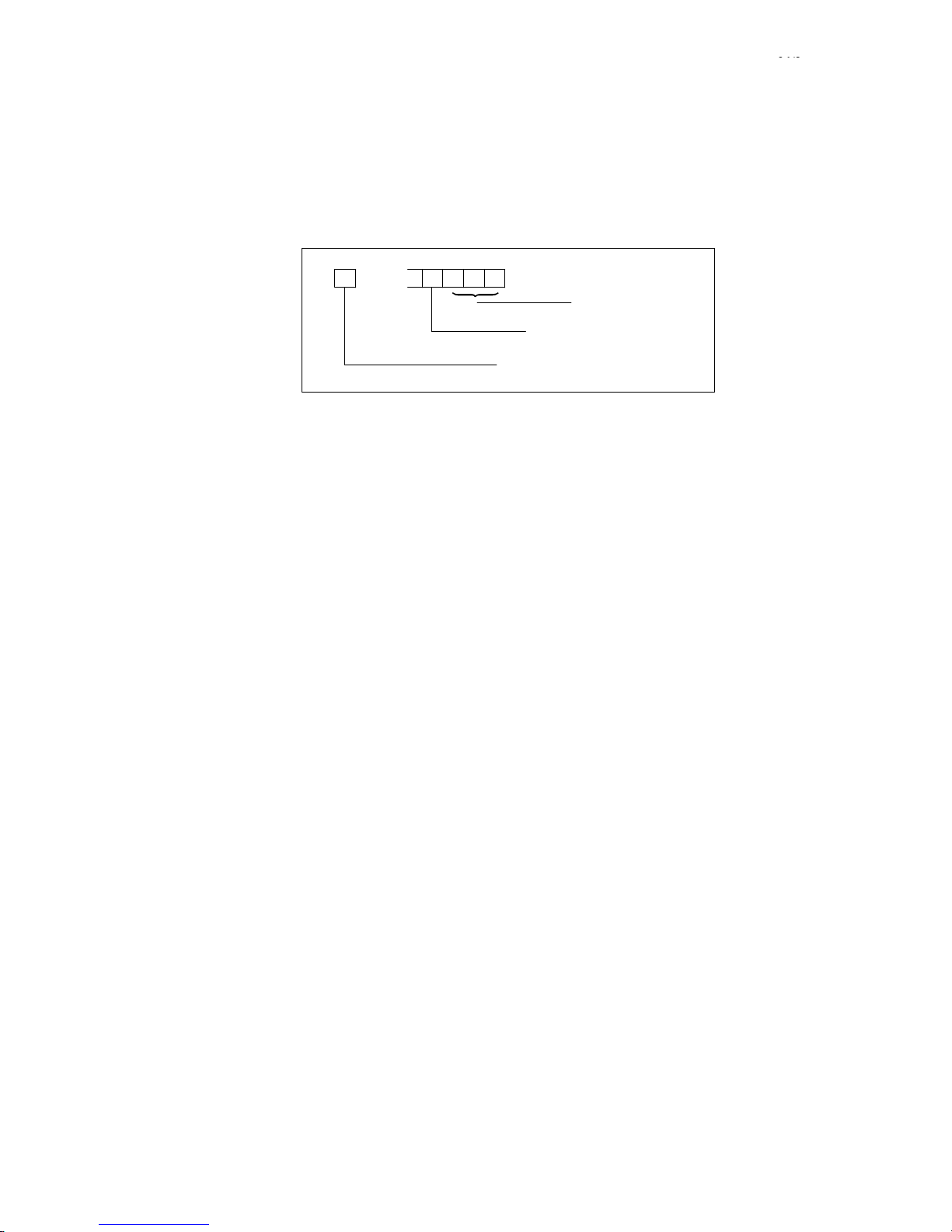
04/96
Siemens AG 2001 All rights reserved 6FC5198–jAB40
1–56
SINUMERIK 840C / SIMODRIVE 611–D (DA)
3098 Error in IKA input/output data CANCEL
On changing input/output assignment of the IKA with inactive relationship (input screen or @40C), not G411.
None
A check is made to determine whether the input/output assignment of an IKA relationship contains permissible
data, and in particular whether the pairs T2/T20, T25/T25, T3/T33 contain compatible values. An error fine coding
ensues relating to block and channel number as follows:
I/O identifier:
IKA relationship
Error fine coding
0 = Input A
1 = Input B
2 = Output
KS
Error fine coding:
1; Error = “Wrong group”
2; Error = “Illegal type of axis”
3; Error = “Wrong axis number”
4; Error = “Axis/channel not available”
5; Error = “Not a real axis”
6; Error = “Wrong R parameter number”
Enter the correct values
3100 Transfer buffer already assigned Acknowledgement key
S During computer link operation
S No data transfer between NC and host computer
This alarm is not displayed but only sent from the NC to the host computer when data is to be transferred from the
computer but the transfer buffer is still occupied.
3101 Program not in memory Acknowledgement key
S When calling a program via computer link
S None
A program has been requested for read-out but is not located in the NC memory.
This alarm is not displayed in the message line but is only indicated in the operator display.
S Check whether program request is correct
3102 Data input disabled FTR Acknowledgement key
When reading in programs via FTR
FTR is aborted
S You have tried to read in a part program via FTR which has already been edited and executed NC internally .
S “Execution from external”
A program with the same number as the program to be executed from external already exists
Stop execution or delete program in the case of “Execution from external”.
3110 Wrong block structure for axis-specific override Acknowledgement key
(2nd step)
When G160 and G161 commands are not programmed alone in a block
S Interlocking of NC START
S Alter the part program
Applies to SW 2 only
Scan
Effect
Explanation
Remedy
Scan
Effect
Explanation
Scan
Effect
Explanation
Remedy
Scan
Effect
Explanation
Remedy
Scan
Effect
Remedy
Note
1 Alarms
1.5.1 Alarm description
01/99
Page 65

04/96
Siemens AG 2001 All rights reserved 6FC5198–jAB40
1–57
SINUMERIK 840C / SIMODRIVE 611–D (DA)
3111 Wrong block struct. for delete dist-to-go Acknowledgement key
S When @736 has not been programmed after the programmed axis movements
S If the axis concerned has not been programmed
S Interlocking of NC START
S Alter the part program
Alarm is displayed with reference to block and channel
3112 Wrong block structure for reciprocation Acknowledgement key
S Reciprocation incorrectly programmed (syntax, reciprocation parameters)
S Too many reciprocation movements in the block
S Interlocking of NC START
S Alter the part program
Applies to SW 2 only
3113 Error on accessing mixed I/O or CSB Acknowledgement key
S MIXED I/O module does not exist or is faulty
S Attempt made to output to CSB without output driver (wrong hardware) or defective CSB output driver, NC MD
312–321 refer to non-existent modules or inputs.
S Interlocking of NC START
S PLC attempts to read from a non-existing module via fast data channel
S Slot in MIXED I/O module
S Check MIXED I/O module
S Replace the CSB module
S Correct NC MD 312 to 321
3157 Stop in thread Acknowledgement key
S During thread cutting a stop has occurred in the revolution feedrate which has destroyed the thread.
S Check axis-specific feedrate lock (DB32)
3158 PLC number not allowed Acknowledgement key
S On selecting via softkey in a configured display
S None
Configured field shows a non-existent PLC number; SINUMERIK 840C has only 1 PLC.
S Check assignments using NC workstation and correct
3159 There is no data block Acknowledgement key
S On selecting via softkey in a configured display
S None
Configured field indicates a non-existent data block.
S Check assignments using NC workstation and correct
Scan
Explanation
Remedy
Note
Scan
Explanation
Remedy
Note
Scan
Explanation
Remedy
Explanation
Remedy
Scan
Effect
Explanation
Remedy
Scan
Effect
Explanation
Remedy
1 Alarms
1.5.1 Alarm description
07/97
Page 66

04/96
Siemens AG 2001 All rights reserved 6FC5198–jAB40
1–58
SINUMERIK 840C / SIMODRIVE 611–D (DA)
3164 Axis conversion error Acknowledgement key
S While executing in AUTOMATIC, MDA or Teach In mode
S Machining stops
S Interlocking of NC START
S The alarm is displayed in channel and block.
S Wrong entries in axis converter list (SD)
– Axis name not entered
– Axis does not exist
Correct axis converter list
Alarm is displayed with reference to block and channel
3166 Program coordination wrong Acknowledgement key
While executing a part program
S Machining stops
Addressed channel has not been defined or is not enabled
Change channel addressing
Define or enable channel
Alarm is displayed with reference to block and channel
3167 T/H word not acknowledged Acknowledgement key
Cyclic
None
S The target channel is not enabled in the PLC MD (signals from channel)
S Routing in target channel has not yet been acknowledged by the user
The current routing and/or error must be acknowledged through the PLC program before the next routing is assigned.
3200 Program coordination syntax wrong Acknowledgement key
When executing a part program
Interlocking of machining
Syntax error: invalid command mnemonics
invalid modification parameters
Correct the faulty command
Alarm is displayed with reference to block and channel
3201 Program coord. too many parameters Acknowledgement key
When executing a part program
Interlocking of machining
More command parameters have been programmed than are permitted in the command description.
Correct the faulty command
Channel-specific
3202 Program coordination area violation Acknowledgement key
When executing a part program
Interlocking of machining
One or more command parameters violate the permitted lower and upper limit values
Correct the faulty command
Alarm is displayed with reference to block and channel
Scan
Effect
Explanation
Remedy
Note
Scan
Effect
Explanation
Remedy
Note
Scan
Effect
Explanation
Remedy
Scan
Effect
Explanation
Remedy
Note
Scan
Effect
Explanation
Remedy
Note
Scan
Effect
Explanation
Remedy
Note
1 Alarms
1.5.1 Alarm description
07/9707/97
Page 67

04/96
Siemens AG 2001 All rights reserved 6FC5198–jAB40
1–59
SINUMERIK 840C / SIMODRIVE 611–D (DA)
3203 Program coord. illegal character Acknowledgement key
When executing a part program
Interlocking of machining
Illegal separators are in the coordination command.
Correct the faulty command
Alarm is displayed with reference to block and channel
3204 Program coord. command incomplete Acknowledgement key
When executing a part program
Interlocking of machining
Parameters or closing brackets are missing in the programmed command
or channel no. = 0
Correct the faulty command
Alarm is displayed with reference to block and channel
3205 Program coord. R parameter error Acknowledgement key
When executing a part program
Interlocking of machining
S An error occurred while programmed R parameters were being substituted
Correct the faulty command
Alarm is displayed with reference to block and channel
3206 Program coord. symbol. paras. not allowed Acknowledgement key
When executing a part program
Interlocking of machining
With the exception of the R parameters, no symbol. parameters are permitted
Correct the faulty command
Alarm is displayed with reference to block and channel
3220 Change from G176 G175 Acknowledgement key
S When executing a part program
S Activated freeze function is terminated leading to G175 function.
During an activated freeze function for angle of rotation, zero offset or length compensation, the ZO group was
changed or the D No. was changed, an angle of rotation offset was activated or a G53 programmed.
These functions result in termination of the “Freeze” function and a change to the G175 function.
S Check program blocks and correct
Channel-specific
3225 Invalid plane specification Acknowledgement key
Before executing a part program
S Processing stops
The plane assignment (cube) and the axis definitions in the channel do not correspond.
Check NC MD 548* 550*552*
Alarm is displayed with reference to channel
Scan
Effect
Explanation
Remedy
Note
Scan
Effect
Explanation
Remedy
Note
Scan
Effect
Explanation
Remedy
Note
Scan
Effect
Explanation
Remedy
Note
Scan
Effect
Explanation
Remedy
Note
Scan
Effect
Explanation
Remedy
Note
1 Alarms
1.5.1 Alarm description
07/97
Page 68

04/96
Siemens AG 2001 All rights reserved 6FC5198–jAB40
1–60
SINUMERIK 840C / SIMODRIVE 611–D (DA)
3226 Invalid G function initial setting Acknowledgement key
Before processing the first block in AUT OMATIC or MDA
S Processing stops
Invalid G function initial settings positions have been entered in the channel-specific machine data.
Check NC MD 108* to 122*
Alarm is displayed with reference to channel
3233 Approach reference point not allowed Reset key
In “AUTOMATIC interrupted” state.
No referencing possible.
If a program is interrupted with the NC STOP key or when changing
from AUTOMA TIC to JOG mode, it must not be possible to activate the submode of JOG, REFPOINT.
(Safety function)
S Reference in program (G74)
S Abort program and reference using keys
3234 There is no target block Acknowledgement key
When block search function is being applied
S Machining stops
S Interlocking of NC START
Block being sought is not in the part program or is to be found after M30
Check entered block number
Applies as from SW 2
Alarm is displayed with reference to channel
3235 End of program missing Acknowledgement key
When executing a part program
Machining stops
The program end M30 is missing in the part program.
Check the part program
Channel-specific
3236 Illegal pole specification Acknowledgement key
When executing a part program
S Machining stop
S Interlocking of NC START
Illegal pole programming with polar coordinates when:
S G110, G111, G112 programmed without having specified a pole plane
S Programmed pole plane with G110, G111, G112 does not correspond to the current pole plane
S G110, G111, G112 programmed with axes and with angles and radii
S Pole displacement (by way of G9 programming) with G10, G11, G12, G13 does not correspond to the current
pole plane
S G10, G11, G12, G13 programmed for the first time without axis specification
S G10, G11, G12, G13 programmed for the first time with G91
S G91 programmed before the angle
S Check the incorrect block in the “Correction block” display.
S The cursor is positioned in front of the incorrect word, if possible.
Alarm is displayed with reference to block and channel
Scan
Effect
Explanation
Remedy
Note
Scan
Effect
Explanation
Remedy
Scan
Effect
Explanation
Remedy
Note
Note
Scan
Effect
Explanation
Remedy
Note
Scan
Effect
Explanation
Remedy
Note
1 Alarms
1.5.1 Alarm description
07/97
Page 69

04/96
Siemens AG 2001 All rights reserved 6FC5198–jAB40
1–61
SINUMERIK 840C / SIMODRIVE 611–D (DA)
3237 Program is being edited Acknowledgement key
When starting read-out via the computer link
Part program is not output
The control tries to output via the computer link a part program which is in the process of being edited.
Terminate editing and repeat read-out process
3238 Program being read-in Acknowledgement key
When starting read-out via the computer link
Part program is not read out
The control tries to output via the computer link a part program which is in the process of being read in via the
computer link
Wait for the end of the read-in process and repeat read-out.
3239 EPROM cycle overwritten by SPF POWER ON
When reading in subroutines via the computer link
Cycle replaced by subroutine
At least one subroutine has been read in which has the same number as an existing cycle. The cycle can
therefore no longer be called from a part program.
The first cycle to be overwritten is displayed in the N number.
Delete the read in subroutine to save the cycle.
To prevent overwriting generally, set MD 5147, bit 3 to 1 on file transfer.
Channel-specific
3240 Subroutine not read-in Acknowledgement key
When reading in subroutines via computer link
At least one subroutine has not been read
The control has attempted to read in at least one subroutine which has the same number as an existing UMS cy-
cle.
The first subroutine not to be read in is displayed in the N number.
If the UMS cycle is to be replaced by a subroutine, the MD 5147, bit 3 must be set to 0 on file transfer.
Channel-specific
3260 Incorrect parameters “Ext. overstore” Reset key
On decoding G421–6.
Decoding stop
When programming G421–6, it is found that the required behaviour requested through the program has been lok-
ked by the machine data parameterization.
Perform no programming or check MD parameterization.
Applies as from SW 4
Alarm is displayed with reference to channel
Scan
Effect
Explanation
Remedy
Scan
Effect
Explanation
Remedy
Scan
Effect
Explanation
Remedy
Note
Scan
Effect
Explanation
Remedy
Note
Scan
Effect
Explanation
Remedy
Note
Note
1 Alarms
1.5.1 Alarm description
Page 70

04/96
Siemens AG 2001 All rights reserved 6FC5198–jAB40
1–62
SINUMERIK 840C / SIMODRIVE 611–D (DA)
3261 Workpiece not available Reset key
At Power On and active MD “Load workpiece last active after Power On”
The workpiece selected in the program pointer cannot be transferred from MMC to NCK.
In the volatile NCK part program memory, a workpiece directory has been opened and not saved to harddisk be-
fore Power Off. After Power On, it is therefore not possible to transfer the workpiece entered in the program pointer
from harddisk to the NCK part program memory.
S Select existing workpiece
S Preselect part program for execution (which means that the program pointer will automatically be assigned to
the workpiece belonging to the preselected part program).
Applies as from SW 4
Alarm is displayed with reference to channel
3262 Error in NCK FB Acknowledgement key
During cyclic operation of control
None
The cyclic routines of the NCK FB have returned a value which is not equal to zero, and have requested the CAN-
CEL alarm class. The return value is output in the alarm as block number N.
Evaluate the block number and check the NCK FB.
Acknowledge the alarm with the Acknowledgement key
S Alarm 3262 is output only if appropriately configured by the machine manufacturer. An error has occurred in
the safety NCK–FB. For more information and remedy, refer to the manufacturer’s documentation.
S Applies as from SW 5.4.
3263 Impermissible axis position Acknowledgement key
When executing a part program
Interlocking of NC START
Machining stops
The position of the material entry coordinate is outside the travel range of the block.
Modify the part program.
Acknowledge the alarm with the Acknowledgement key
Applies as from SW 5.4
Alarm is displayed with reference to channel
3264 NC STOP is effective at the end of block
When pressing NC STOP with active G04 S..., G14 and G24 with set MD bit ”No NC STOP in the dwell block”.
NC–STOP is delayed until the end of block
NC STOP has been pressed in a dwell block in which NC STOP is not to become ef fective. Processing of the
dwell block continues, NS STOP becomes effective only at the end of the block.
The message is deleted when the NC STOP has become effective at the end of the block or when the NC ST OP
request has been cancelled with NC START.
S Alarm channel-specific
S Applies as from SW 5.4
3265 IKA output without enable Cancel key
Cyclically in IPO cycle
Feed stop of ”slave axis” (IKA output variable)
The IKA setpoint output will be disabled because the IKA output variable (normally an axis) was stopped for safety
reasons (e.g. feed disable, follow–up mode, override, controller enable).
Remove the reason for the feed stop.
Caution:
If the reason for the feed stop is no longer present, the IKA link is automatically reactivated. As a result, the
”following error” that has been built up in the meantime is reduced again. The ”reduction” is executed with the
modification limit of the IKA.
Applies as from SW 6, the IKA number will be shown in the block number.
Scan
Effect
Explanation
Remedy
Note
Note
Scan
Effect
Explanation
Remedy
Continuation
Note
Scan
Effect
Explanation
Remedy
Continuation
Note
Note
Scan
Effect
Explanation
Remedy
Note
Scan
Effect
Explanation
Remedy
Note
1 Alarms
1.5.1 Alarm description
07/9709/01
Page 71

04/96
Siemens AG 2001 All rights reserved 6FC5198–jAB40
1–63
SINUMERIK 840C / SIMODRIVE 611–D (DA)
3266 IKA table not calculated Reset key
On selection of IKA
IKA is not effective, machining standstill for all channels from SW 6.4
If a curve that has not (yet) been calculated is used when an IKA is selected, alarm 3266 (IKA table not calculated)
is issued. The number of the curve that has not been calculated is displayed in the ”block number”. The channel
number will always show 1.
Cancel alarm and press button ”Calculate” in the ”Show IKA curves” display or initiate the calculation with @xxx.
Alarm from SW 6.3
3267 Protection zone modification not possible Acknowledgement key
On execution of a part program in automatic or MDI automatic mode
PLC interface signal ”protection zone modification not allowed” (DB 10, DL 16.6) is set.
– MD 3948* ”Coordinate assignment” does not contain coordinates for an axis used in the plane definition,
so that TO and protection zone modification cannot be executed.
– The number of the protection zone is displayed as the ”block number”.
Enter MD 3948* completely and correctly
Alarm from SW 6.3
3280 NC start disable Acknowledgement key
On NC START
None
Interlocking of NC START set internally. User has operated NC START.
Change to the required operating mode or enable the function (e.g. Teach in).
3281 Set-up disable POWER ON
While operating the manual travel keys
None
Set-up disable has been set internally. The user wishes to move an axis with the manual travel keys.
Change to the required operating mode or enable the function (e.g. Teach in).
3282 Data not available Acknowledgement key
While reading in machine data or setting data into the NCK
None
A machine data or setting data which does not exist (or which no longer exists in the present software version) has
been read in.
Remove invalid machine data or setting data from file.
3283 Number range for encoder coarse position exceeded Acknowledgement key
Cancel key
When reading in machine data
None
The stored encoder coarse position is outside the range which can be displayed in MD 3944*. The first start–up of
the function extension of range for EnDat absolute encoder has presumably been carried out incorrectly.
Perform first start–up of the extension of range for EnDat absolute encoder in accordance with the documentation.
4000 Delete alarm
::
::
4220 Parallel straight lines
This area is reserved for measuring cycle messages. The messages are listed in the publication SINUMERIK
840C MEASURING CYCLES.
Scan
Effect
Explanation
Remedy
Note
Scan
Effect
Explanation
Remedy
Note
Scan
Effect
Explanation
Remedy
Scan
Effect
Explanation
Remedy
Scan
Effect
Explanation
Remedy
Acknowledgement
Scan
Effect
Explanation
Remedy
1 Alarms
1.5.1 Alarm description
09/01
Page 72

04/96
Siemens AG 2001 All rights reserved 6FC5198–jAB40
1–64
SINUMERIK 840C / SIMODRIVE 611–D (DA)
1000* Terminal assigned more than once POWER ON
as from SW 2: Reset key
S When inputting machine data for axis assignment
No machining of the axes for which the connection number concerned has been assigned more than once
S Servo disable for the axis concerned
S Mode Group Ready removed
S Interlocking of NC START
S Interlocking of NC RDY relay
S A connection number of a measuring circuit module has been specified more than once under MD200x or
MD384x.
Example: MD3840 = 01060000, MD3845 = 01060000. Connection number 6 of the 1st measuring circuit
module has thus been assigned more than once.
S Check and correct MD200x or MD384x
Applies up to SW 2
1000* Terminal assigned more than once Reset key
S Cyclic for digital drives if double assignment of setpoint output via MD is permissible.
S As before
S Two NC axes assigned the same digital setpoint output are being controlled at the same time. This simulta-
neous output of setpoints at the same drive is not allowed.
The interface signal ”Parking axis” is not allowed for the axis that is not being controlled.
S One of the NC axes must be disconnected from the control loop (servo enable, follow-up mode).
Applies as from SW 3
1004* Permissible feed/limit frequency exceeded Reset key
Cyclic
S Interlocking of NC S TART
S Interlocking of Mode Group Ready
S Setpoint 0
S Servo enable is cancelled after the time in NC MD “Cutout delay”
S Follow-up mode
The maximum value set in the NC MD “Encoder frequency” has been exceeded.
Is only activated for C axes to spindles (assignment via NC MD 461*).
If the service number 309 is indicated here, the reason for the alarm is a format overflow, which can be avoided by
reduction of the resolution.
Check feedrate and NC MD “Encoder limit frequency” MD 308*.
1008* Speed controller limitation Reset key
POWER ON and warm restart
S Interlocking of NC START
S Interlocking of Mode Group Ready
Alarm causes machining stop
S Speed alarm limit has been reached
S Check current controller
S Set speed control loop to a slower rate
S Increase parameters
S Check mechanical parts
Scan
Effect
Explanation
Remedy
Note
Scan
Effect
Explanation
Remedy
Note
Scan
Effect
Explanation
Remedy
Scan
Effect
Explanation
Remedy
1 Alarms
1.5.1 Alarm description
09/01
Page 73

04/96
Siemens AG 2001 All rights reserved 6FC5198–jAB40
1–65
SINUMERIK 840C / SIMODRIVE 611–D (DA)
1012* Parameterization error drive MD (SW 3) Reset key
1012* Parameterization error NC–MD (SW 4 and higher) Reset key
S At POWER ON and warm restart
S Corresponding axes switched to follow-up operation
S Machining stops
S Interlocking of NC START
S Mode Group Ready is removed
Setting error in the NC machine data, e.g.
S Too large a ratio between interpolator clockrate and position control clockrate, because MD160>8
S Too large an internal K
V
(servo gain) factor by specification of
– KV factor (252*)
– Multgain (260*)
– Pulse weighting
S Ratio of cycle rate (MD165) to setting for fine interpolation (MD160) or check of MD584* “Identifier of auxiliary
axes” is not a whole number
S Incorrect measuring system adjustment with MD364* to MD368* (values chosen too large)
S General parameter error in a drive MD
S An illegal value has been entered for the pulse multiplication in connection with the high-resolution measuring
system. Permissible values are: 1, 2, 4, 8, 16, 32, 64 and 128.
S Error in parameterization of the SI machine data.
S Check and new input of the corresponding machine data.
S The AXIS service display shows the service number for the parameterization errors and therefore the exact
cause.(see Diagnostics Guide, Section Parameterization errors spindle/axis).
S Alarm “Parameterization error drive MD”: up to SW 3
S Alarm “Parameterization error NC–MD”: as from SW 4
1016* MS switchover not possible Reset key
When the PLC requests a measuring system switchover
S Interlocking of NC START
S Interlocking of Mode Group Ready
S Setpoint 0
S Servo enable is withdrawn after the time in NC–MD “Cutout delay controller enable” has elapsed
S Follow-up mode
S The difference between measuring system 1 and measuring system 2 is greater than the tolerance specified in
MD 1216*.
Check the mechanical parts and find out the reason for the differences in the measuring value acquisition via the
1st and the 2nd measuring system.
Check sign change actual value 2nd measuring system MD 1824* bit 4, if necessary.
1028* Unable to set reference dimension Reset key
Negative edge of signal DB32, DL K+1, bit 6, (“Set reference dimension”)
S Interlock of NC Start
S Setpoint 0
S No servo enable
S Follow-up mode
If the “Set reference dimension” could not be performed (axis not stationary), the “Reference point reached” signal
is no longer set and also the axis-specific RESET alarm 1028* “Unable to set reference dimension” is triggered.
Make sure that the axes are stationary.
1040* Absolute encoder defective POWER ON
POWER ON
S Interlocking of NC START
S Interlocking of Mode Group Ready
S Machining stops
If a SIPOS absolute encoder with absolute submodule is fitted and the absolute encoder function is selected in MD
1808*, bit 0, the absolute position is requested by the control on POWER ON. If it is not possible to transmit an
absolute position from the encoder without any errors, this alarm is released.
Scan
Effect
Explanation
Remedy
Note
Scan
Effect
Explanation
Remedy
Scan
Effect
Explanation
Remedy
Scan
Effect
Explanation
1 Alarms
1.5.1 Alarm description
Page 74

04/96
Siemens AG 2001 All rights reserved 6FC5198–jAB40
1–66
SINUMERIK 840C / SIMODRIVE 611–D (DA)
Check the encoder hardware (encoder, cable, connectors, absolute submodule). The SIPOS encoder must remain
stationary during transmission of the absolute value, the axis must therefore be held by the brake if necessary.
Drive MD 1033 contains fine coding of errors.
1044* Battery absolute module Acknowledgement key
Cyclic, every 10 minutes
None
The SIPOS encoder has a battery back-up on the absolute submodule so that the absolute position is not lost
even when switched off. The remaining capacity of this battery is checked by the absolute module approximately
every 10 minutes and an alarm is released if a critical minimum limit is reached.
Replace the battery on the absolute module
(see SIPOS absolute encoder description)
1052* Drive fault Reset key
S 611–D alarm 300100 “Drive link off”
S Power On / Reset alarms (ZK1) from 611–D
S Interlocking of NC START
S Interlocking of Mode Group Ready
S Setpoint 0
S Servo enable cancelled after the time set in NC MD “Switchoff delay servo enable” has passed (not with alarm
“Drive link off”)
S Follow-up mode
S 611–D status signals “Drive ready” and “Drive connected” are reset
S Further detailed information on the cause are given in the MMC diagnosis display
Applies as from SW 3
1056* Programmed axis is slave Reset key
S Setpoint specified for a slave axis
S Travel to fixed stop with a slave axis
S Interlocking of NC START
S Follow-up mode
S Cancellation of Mode Group Ready
S Processing interrupt
The designated axis is coupled to its master axis through a speed setpoint coupling. Setpoings should therefore
not be specified.
Setpoints should not be specified for the slave axis.
Applies as from SW 4.4
1064* Output not available POWER ON
Setpoint incorrectly assigned
S Interlocking of NC START
S Interlocking of Mode Group Ready
S Interlocking of NC Ready
S Setpoint 0
S No servo enable
S Follow up mode
A digital setpoint output which does not exist has been assigned
Check the setpoint assignment machine data
Applies as from SW 3
Remedy
Note
Scan
Effect
Explanation
Remedy
Scan
Effect
Explanation
Note
Scan
Effect
Explanation
Remedy
Note
Scan
Effect
Explanation
Remedy
Note
1 Alarms
1.5.1 Alarm description
01/99
Page 75

04/96
Siemens AG 2001 All rights reserved 6FC5198–jAB40
1–67
SINUMERIK 840C / SIMODRIVE 611–D (DA)
1068* Drive fault POWER ON
S 611–D alarms
– Drive configuration faulty
– Ramp-up error (error on 611–D ramp-up. Adjusting data has caused errors)
– Fault along transmission line
S Interlocking of NC START
S Interlocking of Mode Group Ready
S Interlocking of NC Ready
S Setpoint 0
S Servo enable cancelled after the time set in NC MD “Switch off delay servo enable” has passed
S Follow-up mode
S Further detailed information on the cause in MMC diagnosis display
Applies as from SW 3
1076* Measure hardware Reset key
Once only after incorrect operator action/function selection
S Machining stops
S NC Start disable
S Removal of Mode Group Ready
S Invalid measuring circuit assignment
S Pushbutton 2 programmed for SPC/HMS
S Alternating edges programmed for SPC/HMS
S Positive edge programmed for SPC/HMS
S Measuring system change during extended measurement
Check and rectify possible causes of error.
1080* Hardware referencing with passive monitoring axis Reset key
S Referencing
S Interlocking of NC Start
S Follow–up mode
S Mode group ready cancelled
S Machining interrupted
S Referencing is attempted with the axis concerned, but a passive monitoring axis cannot be referenced.
Set reference dimension for passive monitoring axis.
Alarm from SW 6.3
1164* Emergency retraction triggered Reset key
Cyclic in servo cycle when LINK ON is set for following axis (from servo).
Machining interrupted, interlocking of NC START; Mode Group Ready cancelled;
The threshold MD “Emergency retraction threshold” programmed for synchronism monitoring has been exceeded
and “Emergency retraction triggered”.
Condition: enable via PLC interface signal emergency retraction enabled.
Check the drives; check the speed and acceleration limit values of the following axis/spindle; check the
emergency retraction threshold; check the link factors.
Applies as from SW 3
1168* Overlay of FA not enabled Acknowledgement key
Path defined for following axis (NCK).
Setpoint not output, i.e. overlay not executed.
Overlaid offset of following axis although the PLC interface signal “Enable FA overlay” has not been set.
Traverse the following axis with the fictitious leading axis or set PLC interface signal “Enable FA overlay”
Applies as from SW 3
Scan
Effect
Explanation
Note
Scan
Effect
Explanation
Remedy
Scan
Effect
Explanation
Remedy
Note
Scan
Effect
Explanation
Remedy
Note
Scan
Effect
Explanation
Remedy
Note
1 Alarms
1.5.1 Alarm description
01/99
Page 76

04/96
Siemens AG 2001 All rights reserved 6FC5198–jAB40
1–68
SINUMERIK 840C / SIMODRIVE 611–D (DA)
1172* Speed limit exceeded Acknowledgement key
Cyclic in servo cycle when LINK ON has been set for the following axis (from servo)
No reaction, machining not interrupted; the speed of the following axis is limited to the programmed maximum
value; the setpoint determined by the compensatory controller is not used in the calculation.
The maximum value set for the following axis/spindle has been exceeded. Synchronism is in danger.
Reduce feedrate or speed of leading axes. Check the speed limit value. Check the link factors.
Applies as from SW 3
1176* Acceleration limit exceeded Acknowledgement key
Cyclic in servo cycle when LINK ON has been set for the following axis and MD bit “Suppression of acceleration
limitation” is not set (from servo).
No reaction. Machining is not interrupted; when interface signal “Acceleration limitation synchronous” is set; travel
is continued at maximum acceleration; any suppressed partial setpoints are traversed afterwards;
If interface signal “Acceleration limit synchronous” has not been set; any suppressed partial setpoints are not traversed. The setpoint determined by the compensatory controller is not used in the calculation.
The maximum value programmed for the following axis has been exceeded. Synchronism is in danger.
Reduce the acceleration of the leading axes. Check the acceleration limit value. Check the link factors. Set MD bit
“Suppress acceleration limitation”.
Applies as from SW 3
1180* Following spindle corrected autom. Reset key
An error has occurred that has cancelled “Mode Group Ready”.
Cyclic in servo cycle when LINK ON is set
Machining is interrupted. Interlocking of NC START: switchover to actual position link.
An error has occurred for an axis/spindle in the mode group which usually causes a switch over to follow-up mode.
As long as the following axis is not affected by the fault, the link is maintained until “Delay controlled follow-up” has
been executed.
Remove error from faulty axis/spindle.
Applies as from SW 3
1192* Centering edge violated Acknowledgement key
Cyclic in IPO cycle when LINK ON and PLC interface signal “Semi-automatic centring is active” are set.
Interlocking of NC START, any movement towards edges already recognized are suppressed.
The alarm is set when the axis tries to traverse across an edge that has already been recognized or if PLC inter-
face signal “Semi-automatic centring on” and “First edge approached” have been set without first traversing the
following axis.
Move following axis away from the edge (in opposite direction to approach direction: if necessary remove interface
signal “x edge approached” traverse at least 1 increment between interface signal “Semi-automatic centring on”
and “First edge approached”.
Applies as from SW 3 up to SW 4.3
1192* No synchronous/switching positions defined Reset key
When synchronizing or switching on in relation to a position from PLC.
Interlocking of NC START, MACHINING STOP
An attempt has been made to synchronize master and slave axes/spindles from PLC, or to switch on with
reference to a position, without there being any valid switching or synchronizing positions. Synchronization or
switching on with reference to a position is therefore not possible.
For example, specified positions through the GI input display.
Applies as from SW 4.4
Scan
Effect
Explanation
Remedy
Note
Scan
Effect
Explanation
Remedy
Note
Scan
Scan
Effect
Explanation
Remedy
Note
Scan
Effect
Explanation
Remedy
Note
Scan
Effect
Explanation
Remedy
Note
1 Alarms
1.5.1 Alarm description
Page 77

04/96
Siemens AG 2001 All rights reserved 6FC5198–jAB40
1–69
SINUMERIK 840C / SIMODRIVE 611–D (DA)
1196* Reconfiguration not allowed Acknowledgement key
When RECONFIGURING with G function (G401), i.e. when adding, removing a leading axis or changing the link
structure or on CLEAR configuration (from NCK)
Interlocking of NC START
“Reconfiguration allowed” is not set (MD 1844, bit 1)
Correct input, set MD bit
Applies as from SW 3
1200* Division wrong POWER ON
S
Cyclic
S Interlocking of NC S TART
S Machining is interrupted
The “Division from PLC” function is not possible because:
S NC machine data “Number of divisions” has an invalid value
S NC machine data “Absolute division increment” has an invalid value
S NC machine data “Division offset” has an invalid value
S Indexing axis has been defined as a rounding axis, which is impermissible.
S Check and correct the relevant machine data.
1204* Traversing range limits exceeded Reset key
S Cyclic (only with linear axes)
S Interlocking of NC START
S Machining is interrupted
S Set value 0 (abrupt, no deceleration ramp)
If no software limit switches or working area limitations are active, it is theoretically possible to exceed the
maximum possible traversing range (set by the combination of axis-specific position control resolution and input
resolution). As this would lead to traversing errors, however, the traversing range limit is monitored and, when it is
exceeded, alarm 1204* is set.
Traverse back into the permissible range in the opposite direction using INC or JOG mode.
1208* Link factor KF not allowed Acknowledgement key
When entering a new link factor via the G function (from NCK).
Command is not executed, the previous link factor is maintained. Interlocking of NC start.
Denominator J=0 is programmed, link factor incorrectly programmed, following axis not programmed.
Correct link factor
Applies as from SW 3
1212* Overwriting of pos. not allowed Acknowledgement key
When pro g r a m ming a position with GI command.
G command is not executed: interlocking of NC START
GI positions must not be overwritten (enabled with MD 1844 *, bit 3)
Correct input
Applies as from SW 3
1216* Reconfiguration/deletion not allowed Reset key
When RECONFIGURING with G function (G401), i.e. when a leading axis is added or removed or when the link
structure is altered or on DELETE CONFIGURATION (from NCK)
Interlocking of NC START, NC STOP, i.e. channel is stopped: command is not executed: JOG mode still possible.
RECONFIGURA TION or DELETE CONFIGURATION is not possible until LINK OFF has been set.
RECONFIGURA TION is only possible after DELETE CONFIGURATION. Program a new configuration block
(G401); following axis already exists.
First set LINK OFF for the GI grouping in question.
Applies as from SW 3
Scan
Effect
Explanation
Remedy
Note
Scan
Effect
Explanation
Remedy
Scan
Effect
Explanation
Remedy
Scan
Effect
Explanation
Remedy
Note
Scan
Effect
Explanation
Remedy
Note
Scan
Effect
Explanation
Remedy
Note
1 Alarms
1.5.1 Alarm description
Page 78

04/96
Siemens AG 2001 All rights reserved 6FC5198–jAB40
1–70
SINUMERIK 840C / SIMODRIVE 611–D (DA)
1220* GI configuration not allowed Acknowledgement key
When programming DEFINE CONFIGURATION with G function. (From NCK)
Command is not executed. Interlocking of NC START
Possible causes:
S Do leading and following axes have a position measuring system (encoders)?
S Is the following axis linked to itself as a leading axis?
S Can the axis be a following axis (MD 1844*)?
S Link structure switchover not permissible (MD 1844*)
S Link type for the LA/LS not allowed (MD 1456*/496*)?
S The following axes must always be real available axes, i.e. a measuring circuit (POS encoder) must be defi-
ned. A measuring circuit must be defined for leading axes/spindles with link structure K2 (actual position link).
S Leading axes/spindles and following axis are not in the same mode group.
S Not exactly one leading spindle defined for following spindle.
S One of the axes in the GI grouping is a fictitious transformation axis.
S No synchronous positions have been defined for on-the-fly synchronization.
Check configuration
Applies as from SW 3
1224* Change of KF not allowed Acknowledgement key
When a new link factor is entered via G function (from NCK).
The command is not executed, the previous link factor is kept.
Interlocking of NC START
The link factor default setting must not be changed (MD 1844*).
Change default setting if necessary.
Applies as from SW 3
1228* Link factor KF not allowed Reset key
When entering a new link factor via G function (from NCK).
Command is not executed, the previous link factor remains. Interlocking of NC START; NC STOP. Channel stop;
JOG mode still possible.
The entered link factor does not lie within the range 0.00000001 <= /KF/ <= 10.000000 or denominator J = 0 or the
individual values are so high that internal overflows are the result.
Correct or shorten link factor KF
Applies as from SW 3
1232* Change of link factor KF not allowed Reset key
When entering a new link factor via G function (from NCK).
Command is not executed, the previous link factor remains. Interlocking of NC START; NC STOP. Channel stop;
JOG mode still possible.
The link factor default setting must not be changed (MD 1844*).
Change default setting if necessary.
Applies as from SW 3
Scan
Effect
Explanation
Remedy
Note
Scan
Effect
Explanation
Remedy
Note
Scan
Effect
Explanation
Remedy
Note
Scan
Effect
Explanation
Remedy
Note
1 Alarms
1.5.1 Alarm description
Page 79

04/96
Siemens AG 2001 All rights reserved 6FC5198–jAB40
1–71
SINUMERIK 840C / SIMODRIVE 611–D (DA)
1236* GI configuration not allowed Reset key
When programming DEFINE CONFIGURATION via G function. (From NCK)
Command is not executed. Interlocking of NC START; NC STOP, channel stopped; JOG mode still possible.
Possible causes:
S Do leading and following axes have a position measuring system (encoders)?
S Is the following axis linked to itself as a leading axis?
S Can the axis be a following axis (MD 1844*)?
S Link structure switchover not permissible (MD 1844*)
S Link type for the LA/LS not allowed (MD 1456*/496*)?
S The following axes must always be real available axes, i.e. a measuring circuit (POS encoder) must be defi-
ned. A measuring circuit must be defined for leading axes/spindles with link structure K2 (actual position link).
S Leading axes/spindles and following axis are not in the same mode group.
S Not exactly one leading spindle defined for following spindle.
S One of the axes in the GI grouping is a fictitious transformation axis.
S No synchronous positions have been defined for on-the-fly synchronization.
Check configuration
Applies as from SW 3
1240* Following axis not defined Reset key
When programming an axis as a following axis which is not defined as such (from NCK).
G command is not executed. Interlocking of NC START; NC STOP, channel is stopped: JOG mode still possible.
A GI grouping with the stated axis defined as a following axis does not exist.
Correct input.
Applies as from SW 3
1244* Axis not in C axis mode Reset key
The following axis is a C axis, is however not in axis mode.
G command is not executed
Interlocking of NC START; NC STOP, channel is stopped; JOG mode still possible.
For all GI commands except G401, C axis mode must also be set for the C axis which is to be programmed as a
following axis. When G401 is programmed, a GI grouping must not also be defined for the assigned spindle.
Correct input.
Applies as from SW 3
1248* Leading axis not defined Reset key
When programming an axis as a following axis or a spindle as a leading spindle which are not defined as such.
(from NCK)
Command is not executed.
Interlocking of NC START; NC STOP, channel stopped: JOG mode still possible.
A GI grouping with the stated axis defined as a leading axis does not exist.
Correct input.
Applies as from SW 3
1252* Overwriting of GI position not allowed Reset key
When pro g r a m ming a position with GI command.
GI command is not executed.
Interlocking of NC START; NC STOP, channel stopped: JOG mode still possible.
The GI positions cannot be overwritten (enable with MD 1844*, bit 3)
Correct input
Applies as from SW 3
Scan
Effect
Explanation
Remedy
Note
Scan
Effect
Explanation
Remedy
Note
Scan
Effect
Explanation
Remedy
Note
Scan
Effect
Explanation
Remedy
Note
Scan
Effect
Explanation
Remedy
Note
1 Alarms
1.5.1 Alarm description
Page 80

04/96
Siemens AG 2001 All rights reserved 6FC5198–jAB40
1–72
SINUMERIK 840C / SIMODRIVE 611–D (DA)
1256* Retraction axis is following axis Reset key
On decoding the retraction command
None
Alarm occurs when a following axis is defined as retraction axis because the link is violated by the retraction.
Also, the overlay must be enabled by the PLC.
Select another retraction axis.
Applies as from SW 4
1260* Retraction axis in several channels Reset key
With configuration G425/6
Machining interrupt
An axis has been programmed as retraction axis that has already been selected in another channel for retraction.
Remove axis from the retraction block.
Applies as from SW 4
1264* Sel./desel. endl. rot. axis illegal Reset key
On decoding
Machining interrupt
An endlessly rotating rotary axis programmed for a retraction operation should be switched over to normal axis
operation.
Before deselecting the endless rotary axis, write a G block without this rotary axis.
Applies as from SW 4
1268* IKA path reconfiguration illegal Reset key
When programming G401/G411
Interlocking of NC Start
Interlocking of NC Stop
S An IKA path has been defined that is already configured.
S An attempt has been made to delete with G411 an IKA path that is still active.
Activate an IKA path that is not yet configured. On deselection: Switch IKA inactive.
1272* Error in IKA path input/output Reset key
When programming G401/411/G412
Interlocking of NC Start, NC Stop
If an input/output value is specified with G410/G411/412 that does not correspond to the configuration or is not
permissible, this alarm is triggered.
Specify input/output correctly or omit I/O designation with G410.
1276* Illegal software limit switch POWER ON
S After changing MD
S Interlocking of NC START
S Interlocking of Mode Group Ready
S Interlocking of machining stops
An impermissibly high value has been entered in the software limit switch NC MD. The maximum traversing range
of the individual axes is determined by the set axis-specific position control resolution and the input resolution. The
control entered the maximum permissible value in the relevant NC MD when alarm 87 was triggered.
Check software limit switch machine data and correct if necessary.
Applies as from SW 3
Scan
Effect
Explanation
Remedy
Note
Scan
Effect
Explanation
Remedy
Note
Scan
Effect
Explanation
Remedy
Note
Scan
Effect
Explanation
Remedy
Scan
Effect
Explanation
Remedy
Scan
Effect
Explanation
Remedy
Note
1 Alarms
1.5.1 Alarm description
Page 81

04/96
Siemens AG 2001 All rights reserved 6FC5198–jAB40
1–73
SINUMERIK 840C / SIMODRIVE 611–D (DA)
1280* Illegal working area limitation Acknowledgement key
S Cyclic
The control automatically enters the maximum possible value for the traversing range in the working area limitation.
A value has been entered in the minimum or maximum axis-specific working area limitation which is outside the
permissible traversing range of the axis in question.
S Check input
S Check program (G25, G26, @..)
S Take maximum traversing range from table (combination of axis-specific position control resolution and input
resolution).
Applies as from SW 3
1284* Fixed stop not reached Reset key
In the block or on every block change
S Alarm is triggered
S Machining stops
Alarm 1284* is output when the fixed stop is not between the starting and target position in the selection block and
no R parameter has been programmed for function acknowledgement in the selection block.
Ensure that the fixed stop is between the starting and target position in the selection block. Also enter the R parameter number for the function acknowledgement in the selection block.
Applies as from SW 3
1288* No fixed stop axis Reset key
In a block or on every block change
S Programmed path in block is not traversed
S Machining stops
The function, Move Against Fixed Stop, has been selected for an axis which cannot traverse to the fixed stop.
Select the function Move Against Fixed Stop for an axis which is able to. Set MD 1804* for the axis which is to
move against the fixed stop.
Applies as from SW 3
1292* Axis at fixed stop Reset key
In a block or on every block change
Path programmed in block is not traversed
The axes which have moved to the fixed stop cannot be included in an interpolation grouping while the function
Move Against Fixed Stop is active.
Deselect the function move against fixed stop for the axis which is to be part of an interpolation grouping.
Applies as from SW 3
1296* Clamping tolerance exceeded Reset key
While moving against fixed stop
S Interlocking of NC START
S Setpoint 0
S No servo enable
S Follow-up mode
The alarm is triggered if the fixed stop is moved away from by more than the tolerance set in MD 1284*.
Check parameter settings
Applies as from SW 3
Scan
Effect
Explanation
Remedy
Note
Scan
Effect
Explanation
Remedy
Note
Scan
Effect
Explanation
Remedy
Note
Scan
Effect
Explanation
Remedy
Note
Scan
Effect
Explanation
Remedy
Note
1 Alarms
1.5.1 Alarm description
Page 82

04/96
Siemens AG 2001 All rights reserved 6FC5198–jAB40
1–74
SINUMERIK 840C / SIMODRIVE 611–D (DA)
1300* Progr. axis is not a rotary axis CANCEL
When executing AUTOMATIC, MDA and TEACH IN
S Interlocking of NC START
S Machining stop
G[...]103, G[...]104, G[...]105, G[...]119, G195, G295 not programmed in connection with a rotary axis.
Correct the block!
Applies as from SW 4; alarm is channel-specific and block-specific!
1304* Axis turning endlessly Reset key
On block search with calculation
S Cancellation of the block search
An endlessly rotating rotary axis is programmed as contouring axis although the axis is still rotating endlessly.
Stop the endlessly rotating rotary axis and start the block search again.
Applies as from SW 4; alarm is channel-specific and block-specific!
1308* Error in progr. of sim. axis Reset key
When executing a part program
S Machining abort
The “Endlessly rotating rotary axis” is programmed with G[..]119P[..].. without the endless rotation being switched
on.
Correct the block!
Applies as from SW 4; alarm is channel-specific and block-specific!
1312* Error in progr. of sim. axis CANCEL
When executing a part program
S Machining abort
The “Endlessly rotating rotary axis” has been incorrectly programmed.
Correct the block!
Applies as from SW 4; alarm is channel-specific and block-specific!
1316* Programmed position behind SW limit switch Reset key
When executing a part program
Processing stops at indicated block.
The programmed end point of the displayed axis (incl. the active offsets) lies behind the software limit switch.
S Correct program
S Check MD “1st and 2nd software limit switch plus/minus”
S Check PLC interface signal “2nd software limit switch active”
Alarm is displayed axis-specifically, for the block and channel in question.
Alarm applies as from SW 5
1320* Axis not in C axis mode CANCEL
When traversing a C axis that is in spindle mode.
Axis is not traversed.
A C axis has been programmed in spindle mode.
The alarm is only output if MD 5025.5 is set.
Switch C axis to C axis mode.
Scan
Effect
Explanation
Remedy
Note
Scan
Effect
Explanation
Remedy
Note
Scan
Effect
Explanation
Remedy
Note
Scan
Effect
Explanation
Remedy
Note
Scan
Effect
Explanation
Remedy
Note
Scan
Effect
Explanation
Remedy
1 Alarms
1.5.1 Alarm description
07/9707/97
Page 83

04/96
Siemens AG 2001 All rights reserved 6FC5198–jAB40
1–75
SINUMERIK 840C / SIMODRIVE 611–D (DA)
1324* Tolerance for safe standstill exceeded POWER ON
After selection of safe standstill
After initiation of STOP C, D, E and expired timer
Display of the alarm
Initiation of STOP B and A
The axis has moved too far from the set position, i.e. further than permitted in MD 4180*: (standstill tolerance for
safe operation).
Check the tolerance of the standstill monitoring:
If the value does not match the accuracy and dynamic control response of the axis –> increase the tolerance.
If the value matches the accuracy and dynamic control response of the axis –> inspect the machine for damage
and repair the damage.
Applies as from SW 5.4.
1328* Safe speed exceeded Reset key
After selection of safe speed
Display of the alarm
Initiation of STOP C, D, E (depending on configuration)
The axis has moved too quickly, i.e. faster than permitted in MD 4184*, 4188*, 4192*, 4196*: (limit value for safe
speed 1, 2, 3, 4).
If no apparent operating error occurred:
Check the input value of the MD, check the SGEs: of the 4 available speeds, was the correct one selected? If
MDs and SGEs are correct, inspect the machine for damage and repair the damage.
Applies as from SW 5.4.
1332* Safe end position exceeded Reset key
After enabling of the safe end position function
Display of the alarm
Initiation of STOP C, D, E (depending on configuration)
The axis has traveled beyond the end position entered in MD 4200*, 4204*: (upper limit for safe end position 1, 2)
or MD 4208*, 4212*: (lower limit for safe end position 1, 2).
If no apparent operating error occurred:
Check the input value of the MD, check the SGEs: of the 2 end positions, was the correct one selected? If MDs
and SGEs are correct, inspect the machine for damage and repair the damage.
Cancel the user enable for this axis. Then activate the RESET key. The program is aborted and the alarm is
cleared. Move the axis into the valid travel range in JOG mode. When the error in the NC program has been remedied and the position of the axis has been checked, the user enable can be reactivated and the program started.
Applies as from SW 5.4.
1336* Failure in a monitoring channel Reset key
After selection of at least one safety function
Display of the alarm
NC START interlock
STOP F
STOP B and A on active SI function
The comparison of both monitoring channels has uncovered a difference between the input data or the monitoring
results. One of the monitoring functions is no longer operating reliably, i.e. safe monitored operation is no longer
possible.
Find the difference between the monitoring channels. The error code that indicates the cause appears in the following machine data:
on 840C MD 301: diagnostics for STOP F (SI service display)
on 611D MD 1395: diagnostics for STOP F (SI drive display)
The meaning of the error code can be found in the error code table for STOP F on the 840C. It is possible that the
safety–related machine data are no longer identical (load them again if necessary) or that the SGEs do not have
the same signal level (measure again or check in the SI service display). If no such error is found, an error may
have occurred in the CPU, such as a corrupt memory cell. This error can be transient (remedied by POWER ON)
or permanent (reoccurs after POWER ON, in this case replace the hardware).
Remedy the error, and press the RESET key. The program is aborted. If safe monitoring was active, STOP B was
also initiated automatically. In this case, it is necessary to switch the control of f and on (POWER ON).
Applies as from SW 5.4.
Scan
Effect
Explanation
Remedy
Note
Scan
Effect
Explanation
Remedy
Note
Scan
Effect
Explanation
Remedy
Continuation
Note
Scan
Effect
Explanation
Remedy
Continuation
Note
1 Alarms
1.5.1 Alarm description
Page 84

04/96
Siemens AG 2001 All rights reserved 6FC5198–jAB40
1–76
SINUMERIK 840C / SIMODRIVE 611–D (DA)
Table: Error codes for STOP F on 840C
No. Name Explanation Cause, Remedy
0 No error There is no error in this channel, however an error
may have occurred in another channel.
Find the cause in the other channel and interpret the error code
1 Result list 1 Differences in the evaluation of the safe standstill/
safe speed/safe end position functions in the NCK
and drive monitoring channel
e.g. through unbalanced activation of the functions via the SGEs
2 Result list 2 Differences in the evaluation of the SN function in
the NCK and drive monitoring channel
Check the tolerance of the cams
3 Actual position value The difference between the actual position value in
the NCK and drive monitoring channel is greater
than the actual value cross–comparison tolerance
specified in MD 4256* or MD 1342
Incorrect encoder evaluation
(check MDs)
different standstill positions stored
4 No cross–comparison – –
5 Function enables MD 4500*, 4504* and MD 1301 are not identical Enter the same MD values
6 Limit value for SG1 MD 4184* and MD 1331 are not identical Enter the same MD values
7 Limit value for SG2 MD 4188* and MD 1331 are not identical Enter the same MD values
8 Limit value for SG3 MD 4192* and MD 1331 are not identical Enter the same MD values
9 Limit value for SG4 MD 4196* and MD 1331 are not identical Enter the same MD values
10 Standstill tolerance MD 4180* and MD 1330 are not identical Enter the same MD values
11 Upper limit SE1 MD 4200* and MD 1334 are not identical Enter the same MD values
12 Lower limit SE1 MD 4208* and MD 1335 are not identical Enter the same MD values
13 Upper limit SE2 MD 4204* and MD 1334 are not identical Enter the same MD values
14 Lower limit SE2 MD 4212* and MD 1335 are not identical Enter the same MD values
15 Safe cam 1+
(+ Tolerance)
MD 4216* + MD 4248* and MD 1336 + MD 1340
are not identical
Enter the same MD values
16 Safe cam 1+ MD 4216* and MD 1336 are not identical Enter the same MD values
17 Safe cam 1–
(+ Tolerance)
MD 4232* + MD 4248* and MD 1337 + MD 1340
are not identical
Enter the same MD values
18 Safe cam 1– MD 4232* and MD 1337 are not identical Enter the same MD values
19 Safe cam 2+
(+ Tolerance)
MD 4220* + MD 4248* and MD 1336 + MD 1340
are not identical
Enter the same MD values
20 Safe cam 2+ MD 4220* and MD 1336 are not identical Enter the same MD values
21 Safe cam 2–
(+ Tolerance)
MD 4236* + MD 4248* and MD 1337 + MD 1340
are not identical
Enter the same MD values
22 Safe cam 2– MD 4236* and MD 1337 are not identical Enter the same MD values
23 Safe cam 3+
(+ Tolerance)
MD 4224* + MD 4248* and MD 1336 + MD 1340
are not identical
Enter the same MD values
24 Safe cam 3+ MD 4224* and MD 1336 are not identical Enter the same MD values
25 Safe cam 3–
(+ Tolerance)
MD 4240* + MD 4248* and MD 1337 + MD 1340
are not identical
Enter the same MD values
26 Safe cam 3– MD 4240* and MD 1337 are not identical Enter the same MD values
27 Safe cam 4+
(+ Tolerance)
MD 4228* + MD 4248* and MD 1336 + MD 1340
are not identical
Enter the same MD values
28 Safe cam 4+ MD 4228* and MD 1336 are not identical Enter the same MD values
29 Safe cam 4–
(+ Tolerance)
MD 4244* + MD 4248* and MD 1337 + MD 1340
are not identical
Enter the same MD values
30 Safe cam 4– MD 4244* and MD 1337 are not identical Enter the same MD values
31 Position tolerance MD 4256* and MD 1342 are not identical Enter the same MD values
32 Reference position tolerance MD 4252* and MD 1344 are not identical Enter the same MD values
33 Time/velocity switchover MD 4264* and MD 1351 are not identical Enter the same MD values
34 T olerance time/ SGE switch-
over
MD 4260* and MD 1350 are not identical Enter the same MD values
1 Alarms
1.5.1 Alarm description
Page 85

04/96
Siemens AG 2001 All rights reserved 6FC5198–jAB40
1–77
SINUMERIK 840C / SIMODRIVE 611–D (DA)
No. Cause, RemedyExplanationName
35 Delay time pulse deletion MD 4268* and MD 1356 are not identical Enter the same MD values
36 Time for pulse deletion check MD 4272* and MD 1357 are not identical Enter the same MD values
37 Transition time STOP C to
SBH
MD 4276* and MD 1352 are not identical Enter the same MD values
38 Transition time STOP D to
SBH
MD 4280* and MD 1353 are not identical Enter the same MD values
39 Transition time STOP E to
SBH
MD 4284* and MD 1354 are not identical Enter the same MD values
40 Stop reaction after SG MD 4508*.4,4508*.5 and MD 1361 are not identical Enter the same MD values
41 Stop reaction after SE MD 4508*.2,4508*.3 and MD 1362 are not identical Enter the same MD values
42 Shut–down speed pulse dele-
tion
MD 4288* and MD 1360 are not identical Enter the same MD values
43 Memory test stop reaction – –
44 Position actual value+limit va-
lue SG1
Position actual value (error code 3) different or
MD 4184* and MD 1331[0] not equal (error code 6)
–
45 Position actual value–limit va-
lue SG1
Position actual value (error code 3) different or
MD 4184* and MD 1331[0] not equal (error code 6)
–
46 Position actual value+limit va-
lue SG2
Position actual value (error code 3) different or
MD 4188* and MD 1331[1] not equal (error code 7)
–
47 Position actual value–limit va-
lue SG2
Position actual value (error code 3) different or
MD 4188* and MD 1331[1] not equal (error code 7)
–
48 Position actual value+limit va-
lue SG3
Position actual value (error code 3) different or
MD 4192* and MD 1331[2] not equal (error code 8)
–
49 Position actual value–limit va-
lue SG3
Position actual value (error code 3) different or
MD 4192* and MD 1331[2] not equal (error code 8)
–
50 Position actual value+limit va-
lue SG4
Position actual value (error code 3) different or
MD 4196* and MD 1331[3] not equal (error code 9)
–
51 Position actual value–limit va-
lue SG4
Position actual value (error code 3) different or
MD 4196* and MD 1331[3] not equal (error code 9)
–
52 Standstill position + tolerance Position actual value (error code 3) dif ferent or
MD 4180* and MD 1330 not equal (error code 10)
–
53 Standstill position – tolerance Position actual value (error code 3) different or
MD 4180* and MD 1330 not equal (error code 10)
–
54 Position actual value+nx+tole-
rance
Position actual value (error code 3) different or
MD 4292* and MD 1346 not equal (error code 75)
or MD 4256* and MD 1342 not equal (error
code 31)
–
55 Position actual value+n
x
Position actual value (error code 3) different or
MD 4292* and MD 1346 not equal (error code 75)
–
56 Position actual value–n
x
Position actual value (error code 3) different or
MD 4292* and MD 1346 not equal (error code 75)
–
57 Position actual value–nx–tole-
rance
Position actual value (error code 3) different or
MD 4292* and MD 1346 not equal (error code 75)
or MD 4256* and MD 1342 not equal (error
code 31)
–
58 Stop request MD 1301 bit 6 is not 0 –
59 SG correction factor 1 MD 1301 bit 5 is not 0 –
60 SG correction factor 2 MD 1301 bit 5 is not 0 –
61 SG correction factor 3 MD 1301 bit 5 is not 0 –
62 SG correction factor 4 MD 1301 bit 5 is not 0 –
63 SG correction factor 5 MD 1301 bit 5 is not 0 –
64 SG correction factor 6 MD 1301 bit 5 is not 0 –
65 SG correction factor 7 MD 1301 bit 5 is not 0 –
66 SG correction factor 8 MD 1301 bit 5 is not 0 –
67 SG correction factor 9 MD 1301 bit 5 is not 0 –
68 SG correction factor 10 MD 1301 bit 5 is not 0 –
69 SG correction factor 11 MD 1301 bit 5 is not 0 –
70 SG correction factor 12 MD 1301 bit 5 is not 0 –
71 SG correction factor 13 MD 1301 bit 5 is not 0 –
72 SG correction factor 14 MD 1301 bit 5 is not 0 –
1 Alarms
1.5.1 Alarm description
07/97
Page 86

04/96
Siemens AG 2001 All rights reserved 6FC5198–jAB40
1–78
SINUMERIK 840C / SIMODRIVE 611–D (DA)
No. Cause, RemedyExplanationName
73 SG correction factor 15 MD 1301 bit 5 is not 0 –
74 SG correction factor 16 MD 1301 bit 5 is not 0 –
75 Velocity limit n
x
MD 4292* and MD 1346 not equal Enter MDs equal
76 Stop reaction with SG1 MD 4508*.4, 4508*.5 and MD 1361 not equal Enter MDs equal
77 Stop reaction with SG2 MD 4508*.4, 4508*.5 and MD 1361 not equal Enter MDs equal
78 Stop reaction with SG3 MD 4508*.4, 4508*.5 and MD 1361 not equal Enter MDs equal
79 Stop reaction with SG4 MD 4508*.4, 4508*.5 and MD 1361 not equal Enter MDs equal
80 SI modulo value for SN MD 1367 is not 0 Enter MDs equal
81 Speed tolerance for SBR MD 4296* and MD 1348 not equal Enter MDs equal
1000 Control timer expired The SGE modification timer did not expire within
the time of the control timer (i.e. too many switching
operations in SGEs).
e.g. contact problems (loose contact)
1001 Control timer initialization error The SGE modification timer did not start the control
timer.
–
1002 User enable timer expired Different status of user enable from drive and NCK –
1003 Reference tolerance violated The comparison of stored standstill position and
current position has a greater deviation than speci-
fied in MD 4252*: actual value tolerance (referenc-
ing) or MD 1344
–
1004 Plausibility violation of user
enable
The user enable has been specified for an axis
which is
– already referenced
– not yet referenced
–
1005 Pulses already deleted on test
stop selection
The ”pulses are deleted” signal is already active on
test stop selection
Test stop selection on pulse enable error during wiring of the
”pulses are deleted” SGE
1006 Error on SGA forced dynamic
response
An error was detected on the cyclic check of the
SGAs.
–
1007 Breakdown of the communi-
cation between PLC and drive
If the drive releases a breakdown in communica-
tion, either the PLC or the NC has broken down.
1008 Erroneous data transfer bet-
ween PLC and drive
The data transfer of the SGEs/SGAs between PLC
and drive is guaranteed by a checksum. In the
event of an error, the calculated checksum does
not coincide with the transferred checksum. If the
stop is released by the drive, either the PLC or the
NC has broken down.
Note:
If the value 12 is stored in this value, the cross–comparison has detected a difference in the MD for lower limit SE1 in the NCK
and drive monitoring channel.
1 Alarms
1.5.1 Alarm description
07/97
Page 87

04/96
Siemens AG 2001 All rights reserved 6FC5198–jAB40
1–79
SINUMERIK 840C / SIMODRIVE 611–D (DA)
1340* Axis has not been referenced safely
After selection of SE/SN
Display of the alarm
The ”axis has been referenced safely” SGA is not enabled
The safe end positions are not active
The safe cams are output, but are not safe
1. The axis has not been referenced, or
2. The user enable for this axis is missing or has been canceled. This can occur, for example, if the axis is
moved after the machine is switched off, with the result that the standstill position, which was stored before the
machine was switched off, is no longer correct.
for 1. Reference the axis
for 2. Activate the user enable
The alarm disappears automatically when the enable has been activated
If the axis has not been referenced safely, and the user enable is not active:
S The safe cams are active but not yet safe
S The safe end positions are not yet active
Applies as from SW 5.4.
1344* Test stop running
After selection of at least one safety function
Display of the alarm
The correct operation of the shut–down path is tested by enabling the ”test stop selection” SGE.
One is not necessary. It is used exclusively to inform the operator. The alarm disappears automatically when the
delay time defined in MD 4272*: (time for checking pulse deletion) expires, if the control detects pulse deletion, i.e.
if the test was successfully completed.
Applies as from SW 5.4.
1348* Stop E triggered Reset key
After selection of SG, SE
Interlocking of NC START
Initiation of ESR
Activation of SBH
Follow–up mode for all axes of this mode group
Removal of Mode Group Ready
Interruption of machining
This alarm occurs with the alarms ”safe speed exceeded” or ”safe position exceeded” (when configured accord-
ingly in MD 4508* Bit 4: (STOP D/E selection for SG) or MD 4508* Bit 2: (STOP D/E selection for SE). It indicates
the initiation of a configured ESR and the internal activation of safe standstill.
Remedy the causes of ”safe speed exceeded” or ”safe end position exceeded” (see description of the alarms).
Remedy the error and press the RESET key (the program is aborted and must be restarted).
Applies as from SW 5.4.
1352* Stop D triggered Reset key
After selection of SG, SE
Interlocking of NC START
Braking on the path
Activation of SBH
Interruption of machining
This alarm occurs with the alarms ”safe speed exceeded” or ”safe position exceeded” (when configured accordingly in MD 4508* Bit 4: (STOP D/E selection for SG) or MD 4508* Bit 2: (STOP D/E selection for SE). It indicates
the initiation of ”braking on the path” and the internal activation of ”safe standstill monitoring”.
Remedy the causes of ”safe speed exceeded” or ”safe end position exceeded” (see description of the alarms).
Remedy the error and press the RESET key (the program is aborted and must be restarted).
Applies as from SW 5.4.
Scan
Effect
Explanation
Remedy
Warning!
Note
Scan
Effect
Explanation
Remedy
Note
Scan
Effect
Explanation
Remedy
Continuation
Note
Scan
Effect
Explanation
Remedy
Continuation
Note
1 Alarms
1.5.1 Alarm description
Page 88

04/96
Siemens AG 2001 All rights reserved 6FC5198–jAB40
1–80
SINUMERIK 840C / SIMODRIVE 611–D (DA)
1356* Stop C triggered Reset key
After selection of SG, SE
Interlocking of NC START
Follow–up mode for all axes of this mode group
Removal of Mode Group Ready
Interruption of machining
This alarm occurs with the alarms ”safe speed exceeded” or ”safe position exceeded” (when configured accordingly in MD 4508* Bit 4: (STOP D/E selection for SG) or MD 4508* Bit 2: (STOP D/E selection for SE). It indicates
the initiation of ”braking at the current limit” and the internal activation of the ”safe standstill”.
Remedy the causes of ”safe speed exceeded” or ”safe end position exceeded” (see description of the alarms).
Remedy the error and press the RESET key (the program is aborted and must be restarted).
Applies as from SW 5.4.
1360* Stop B triggered POWER ON
After selection of SG, SE after selection of SBH
After initiation of STOP C, D, E
After initiation of STOP F and activated SBH/SG or SE, SN
Interlocking of NC START
Follow–up mode for all axes of this mode group
Removal of Mode Group Ready
Interruption of machining
Pulse deletion after timer expires (SGA)
This alarm occurs with the alarm ”tolerance for safe standstill exceeded” or alarm ”STOP F triggered”. It indicates
the initiation of ”braking at the current limit” and the internal activation of the timer for switchover to STOP A (see
MD 4268*: (pulse deletion delay time).
Remedy the causes of ”tolerance for safe standstill exceeded” or for ”STOP F triggered” (see description of the
alarms).
Not possible. Acknowledgement of the alarm only possible by POWER ON.
Applies as from SW 5.4.
1364* Stop A triggered POWER ON
After selection of SBH
After initiation of STOP B
Interlocking of NC START
Removal of Mode Group Ready
Interruption of machining
Immediate pulse deletion (SGA)
This alarm occurs with the alarm ”tolerance for safe standstill exceeded” or as a result of STOP B or an unsuccessful test stop. It indicates the initiation of a ”pulse deletion”.
Remedy the causes of ”tolerance for safe standstill exceeded” or for ”STOP F triggered” (see description of the
alarms).
Not possible. Acknowledgement of the alarm only possible by POWER ON.
Applies as from SW 5.4.
1368* Protection zone collision plus RESET
Cyclic with active function ”Collision monitoring”
Axis number
Machining standstill;
disabling of NC Start
Overlap of two protection zones has been recognized
Travel free and trigger mode group reset
Applies as from SW 6.
Scan
Effect
Explanation
Remedy
Continuation
Note
Scan
Effect
Explanation
Remedy
Continuation
Note
Scan
Effect
Explanation
Remedy
Continuation
Note
Scan
Parameters
Effect
Explanation
Remedy
Note
1 Alarms
1.5.1 Alarm description
07/97
Page 89

04/96
Siemens AG 2001 All rights reserved 6FC5198–jAB40
1–81
SINUMERIK 840C / SIMODRIVE 611–D (DA)
1372* Protection zone collision minus RESET
Cyclic with active function ”Collision monitoring”
Axis number
Machining standstill;
disabling of NC Start
Overlap of two protection zones has been recognized
Travel free and trigger mode group reset
Applies as from SW 6.
1376* Check absolute value encoder position Cancel key
S Loading of complete NC MD files
S Absolute value encoder available and range expansion of Endat absolute value encoder parameterized
None
Startup, whjich is to be performed by loading an NC MD file, has possibly not yet been terminated on an axis with
absolute value encoder. The start–up engineer must then decide whether further startup steps have to be carried
out. This alarm remains present even after Power Off.
S Bring axes to closed–loop control mode (terminate possible initial clear mode) and check the actual postion
displayed.
S If the actual postion is not correct (e.g. after loss of data in SRAM through hardware replacement), startup
steps must be carried out.
S Acknowledge alarm (not possible in initial clear mode!)
2000* LEC – grid spacing illegal POWER ON
Cyclic
Removal of N C S TART
In the case of the spindle (e.g. synchronous spindle mode), a modulo value has been entered for the axis concer-
ned which cannot be divided exactly into 360°, which means that the grid spacing is not equal.
Check NC MD* 3440*
Applies as from SW 3
2001* Speed setpoint warning limit responded Reset key
Cyclic
Interlocking of NC START
S The setpoint on the DAC is higher than entered in NC MD 268* “Max. speed setpoint (DAC)”. It is not possible
to increase the setpoint any further.
The alarm 2001* “Speed setpoint warning limit” can occur when an M19 positioning is requested while the
drive unit is not ready (e.g. setpoint cable break: actuator switched off; actuator not enabled by PLC).
S An incorrect feedback polarity has been parameterized in the spindle positioning mode (sign error).
S Traverse at slower speed
S Check the actual values (encoder)
S Check NC MD “Max. speed setpoint (DAC)”
S Check the drive actuator
Scan
Parameters
Effect
Explanation
Remedy
Note
Scan
Effect
Explanation
Remedy
Scan
Effect
Explanation
Remedy
Note
Scan
Effect
Explanation
Remedy
1 Alarms
1.5.1 Alarm description
07/97
Page 90

04/96
Siemens AG 2001 All rights reserved 6FC5198–jAB40
1–82
SINUMERIK 840C / SIMODRIVE 611–D (DA)
2003* Zero speed monitoring Reset key
S When accelerating
S When at zero speed
S When clamped
S When decelerating (delay)
S Interlock of NC START
S Interlock of Mode Group Ready
S Setpoint 0
S Servo enable is removed on expiry of the time in NC–MD “Cutoff delay servo enable”
S Follow-up mode
S When positioning, the following error could not be eliminated faster than the time given in NC–MD “Cutoff delay
servo enable”.
S When clamped, the limit defined in the NC–MD “Zero speed monitoring” has been exceeded.
S Mechanically clamped spindle has been pushed out of position.
S Error on the activating device, on the tacho, on the motor, in the mechanical construction, in the CNC measu-
ring circuit hardware or on/in the encoder.
S Wrong setpoint output assignment specified
S When starting up: wrong sense of position control
S NC–MD “Zero speed monitoring” must be greater than NC–MD “Exact stop limit coarse”.
S NC–MD “Cutoff delay servo enable” must be great enough for the following error to be eliminated within this
time (applies only when NC–MD “Delay zero speed monitoring” = 0).
S NC–MD “Delay zero speed monitoring” must be great enough for the following error of the various spindles to
be eliminated within the time entered.
S Check actual values (encoder) and sense of position control.
2007* There is no measuring circuit POWER ON
S On POWER ON
S Spindle is not processed
S Servo disable of spindle concerned
S Removal of Mode Group Ready
S Interlocking of NC START
S Interlocking of NC RDY relay
S MD 400* and/or MD 460* indicates an empty submodule slot on a measuring circuit module with submodules.
Example: MD 460* = 01090000, the first measuring circuit module is an HMS module with empty submodule
slot 2.
S Measuring circuit module has been removed or is defective.
S Compare MD 400* and/or MD 460* with the hardware configuration and correct.
2008* Closed-loop hardware spindle POWER ON
Cyclic
S Interlocking of NC S TART
S Setpoint relay drops out, setpoint 0
S Removal of Mode Group Ready
S Spindle servo enable is removed after the time in MD “Delay for servo enable” has elapsed.
The measuring circuit difference signals
S are not in phase
S have a short circuit to groand
S are absent
S Check wether the measuring circuit connector has been inserted
S The measuring circuit short circuit connector can be slotted in to check whether the measuring circuit module
is functioning correctly.
S Check the difference signals with the oscilloscope
S Replace the encoder/cable
Scan
Effect
Explanation
Remedy
Scan
Effect
Explanation
Remedy
Scan
Effect
Explanation
Remedy
1 Alarms
1.5.1 Alarm description
Page 91

04/96
Siemens AG 2001 All rights reserved 6FC5198–jAB40
1–83
SINUMERIK 840C / SIMODRIVE 611–D (DA)
2009* Contamination measuring system spindle POWER ON
S Cyclic
S Interlocking of NC S TART
S Interlocking of Mode Group Ready
S Where measuring systems have a contamination signal (e.g. EXE) an error is sent to the NC from the measu-
ring system.
S Check the measuring system against the manufacturer’s specifications.
2010* Pulse code monitoring Reset key
S Cyclic
S Interlocking of Mode Group Ready
S Interlocking of NC START
S Alarm causes machining stop
S Transmission error or interference from encoder
S Check encoder, cable, connecter
2011* Zero marks monitoring has responded Reset key
S Cyclic, depending on the tolerance band set for the difference pulses
S Interlocking of NC START
S Machining stops
Pulses have been lost per encoder revolution, above the permitted tolerance band, due to transmission errors,
interference or too high speed. The reference counter checks this zero mark.
S Check the encoder pulses
S Check transmission path
2014* Setpoint or actual speed alarm limit exceeded Reset key
2014* Speed setpoint value alarm limit responded Reset key
Cyclic
S Interlocking of NC S TART
S Interlocking of Mode Group Ready
S Setpoint 0
S Servo enable is removed after the time in NC MD “Cutout delay servo enable” has elapsed
S Follow-up mode
S The motor could not follow the entered speed setpoint.
S During start-up: incorrect position control direction, incorrect spindle multgain
S The speed actual value exceeds the maximum spindle speed + tolerance
If the service number 309 is indicated here, the reason for the alarm is a format overflow, which can be avoided by
reduction of the resolution. Another reason can also be the resolution of the C axis assigned.
S Check the drive
S Check position control direction
S Match spindle multgain (MD 468*)
S Check speed setpoint cable
S Check actual values (pulse encoder)
S Increase spindle speed tolerance (MD 445*)
S Increase acceleration time constant (MD 419* – 426*)
S Alarm ”Setpoint or actual speed alarm limit exceeded”: up to SW 3
S Alarm ”Speed setpoint alarm limit actuated”: as from SW 4
2015* Drift too high Reset key
With input of NC MD 401* or with semi-automatic drift compensation (axis only)
Interlocking of NC START
The entered drift is greater than approx. 500 mV . In the case of semi-automatic drift compensation, the drift to be
compensated for by the NC has risen to above approx. 500 mV .
Check whether the drift has been compensated for correctly at the driving unit.
Scan
Effect
Explanation
Remedy
Scan
Effect
Explanation
Remedy
Scan
Effect
Explanation
Remedy
Scan
Effect
Explanation
Remedy
Note
Scan
Effect
Explanation
Remedy
1 Alarms
1.5.1 Alarm description
07/97
Page 92

04/96
Siemens AG 2001 All rights reserved 6FC5198–jAB40
1–84
SINUMERIK 840C / SIMODRIVE 611–D (DA)
2016* Terminal assigned more than once POWER ON
as from SW 3: Reset key
S
During machine data input for spindle assignment
No processing of the spindles of which the corresponding connection number has been assigned more than once.
S Servo disable for the spindle in question
S Removal of Mode Group Ready
S Interlocking of NC START
S Interlocking of NC RDY relay
S A connection number of a measuring circuit module is entered several times in MD 400* and/or MD 460*.
Example: MD 4600 = 01060000, MD 4605 = 01060000. Connection number 6 of the 1st measuring circuit
module is thus assigned several times.
S Check and correct MD 400* and/or MD 460*.
2018* Speed controller limitation Reset key
Cyclic
S Interlocking of Mode Group Ready
S Interlocking of NC START
S Alarm causes machining to stop
S Speed controller limitation triggered
S Check current control. Set speed control loop slower.
S Check SIMODRIVE
S Check machine
Scan
Effect
Explanation
Remedy
Scan
Effect
Explanation
Remedy
1 Alarms
1.5.1 Alarm description
Page 93

04/96
Siemens AG 2001 All rights reserved 6FC5198–jAB40
1–85
SINUMERIK 840C / SIMODRIVE 611–D (DA)
2019* Parameterization error NC MD Reset key
2019* Parameterization error NC MD Reset key
S At POWER ON or warm restart
S The spindles concerned are switched to follow-up mode
S Machining stops
S Interlocking of NC START
S Mode Group Ready removed
Input error in machine data, e.g.
S Ratio of interpolator pulse to position control pulse too great because MD 160 > 80
S Internal servo gain (K
V
) factor too large due to
– Servo gain factor (469*)
– Multgain (468*)
– Pulse weighting
S No whole-number ratio between entry in MD 165 (timing ratio) and MD 160 (fine interpolation)
S Incorrect measuring system adaptation in MD 455* to MD 456*
(values selected too large)
S General parameterization error of a drive MD
S The pulse multiplication value entered for the high-resolution measuring system is impermissible. The following
values are permissible: 1, 2, 4, 8, 16, 32, 64 and 128.
S Check and new input of the corresponding machine data.
S Error in parameterization of the SI machine data.
S The SPINDLE service display displays the service number for parameterization errors and with it the exact
cause (see Diagnostics Guide, Section Parameterization errors spindle/axis).
S Alarm “Parameterization error drive MD”: up to SW 3
S Alarm “Parameterization error NC–MD”: as from SW 4
2021* Spindle not synchronized Reset key
On execution of an M19 command
Machining stops
M19 was used to approach a spindle position, although the spindle had not yet been synchronized.
Synchronize the spindle; execute the M19 again.
2028* MD M19 not selected Reset key
When executing in AUTOMATIC mode or input in MDA or external
S Machining stops
“M19 S...” has been programmed in the part program although this function is not implemented in the control.
S Check program
S Check NC MD
Scan
Effect
Explanation
Remedy
Note
Scan
Effect
Explanation
Remedy
Scan
Effect
Explanation
Remedy
1 Alarms
1.5.1 Alarm description
Page 94

04/96
Siemens AG 2001 All rights reserved 6FC5198–jAB40
1–86
SINUMERIK 840C / SIMODRIVE 611–D (DA)
2029* Drive fault Reset key
S 611–D alarm 300100 “Drive link off”
S Power On / Reset alarms (ZK1) from 611–D
S Interlocking of NC START
S Interlocking of Mode Group Ready
S Setpoint 0
S Setpoint enable is removed after the time set in NC MD “Switch off delay servo enable” (not with alarm “Drive
link off”)
S Follow up mode
S 611–D status signals “Drive ready” and “Drive connected” are reset
S Further detailed information on the cause in MMC diagnosis display
Applies as from SW 3
2030* Spindle speed too high Reset key
Only when NC MD “Encoder available” is set
S Machining stops
S Interlocking of NC START
S Interlocking of Mode Group Ready
The spindle speed is higher than defined in the machine data or setting data.
S Program a smaller S value
S NC MD “Max spindle speed for 1st to 8th gearing”
S NC MD “Tolerance band of max. spindle speed”
S NC MD “Max. spindle speed”
S Check PLC gear speed
S Check G92 S... at “v = constant”
S Check setting data of spindle speed limitation
S Program G26 S...
2032* Output not available POWER ON
When setpoint incorrectly assigned
S Interlocking of NC START
S Interlocking of Mode Group Ready
S Interlocking of NC Ready
S Setpoint 0
S No servo enable
S Follow-up mode
A digital setpoint output that does not exist has been assigned
Check the setpoint output machine data
Applies as from SW 3
2033* Drive fault POWER ON
S 611–D alarms
– Drive configuration description incorrect
–– Drive number
–– Drive type (FDD/MSD)
–– Module type (single-axis/double-axis module)
– Ramp up error (error during 611–D rump-up, error during data matching)
– Transmission line fault (CRC, bus timeout)
S Interlocking of NC START
S Interlocking of Mode Group Ready
S Interlocking of NC Ready
S Setpoint 0
S Servo enable removed after time set in NC MD “Switchoff delay servo enable” has passed
S Follow-up mode
Additional detailed information about the cause is given in the MMC diagnosis display
Applies as from SW 3
Scan
Remedy
Note
Scan
Effect
Explanation
Remedy
Scan
Effect
Explanation
Remedy
Note
Scan
Effect
Remedy
Note
1 Alarms
1.5.1 Alarm description
Page 95

04/96
Siemens AG 2001 All rights reserved 6FC5198–jAB40
1–87
SINUMERIK 840C / SIMODRIVE 611–D (DA)
2057* Emergency retraction triggered Reset key
Cyclic in servo cycle, when LINK ON is set for the following spindle (from servo).
Machining interrupted, interlocking of NC START; Mode Group Ready cancelled
The threshold MD “Emergency retraction threshold” programmed for synchronism monitoring has been exceeded
and emergency retraction triggered.
Prerequisite: Enable with PLC interface signal “Emergency retraction enabled”.
Check the drives; check the speed and acceleration limit values of the following spindle; check the emergency
retraction threshold; check the link factors.
Applies as from SW 3
2058* Overlay of following axis not enabled Acknowledgement key
When path for following axis defined (NCK).
Setpoint is not output, i.e. the overlay is not executed.
Overlaid offset of the following spindle although the PLC interface signal “Enable FA overlay” is not set.
Traverse a following axis with fictitious leading axis or set PLC interface signal “Enable FA overlay”.
Applies as from SW 3
2059* Speed limit exceeded Acknowledgement key
Cyclic in servo cycle, when LINK ON is set for following spindle (from servo)
S No reaction
S Machining is not interrupted
The speed of the following spindle is limited to the programmed maximum value; the setpoint determined by the
compensatory controller is not included in the calculation.
The maximum value programmed for the following spindle has been exceeded. Synchronism is at risk
S Reduce feedrate or speed of leading spindles
S Check the speed limit value
S Check the link factors
Applies as from SW 3
2060* Acceleration limit exceeded Acknowledgement key
Cyclic in servo cycle, when LINK ON is set for the following spindle and MD bit “Suppress acceleration limitation”
(MD 526*) is not set (from servo).
S No reaction
S Machining is not interrupted
Interface signal “Acceleration limitation synchronous” is set, spindle continues to travel at maximum acceleration;
any suppressed TSW are traversed afterwards. If interface signal “Acceleration limitation synchronous” is not set,
suppressed partial setpoints are not traversed. The setpoint determined by the compensatory controller is not
included in the calculations.
Maximum value programmed for the following spindle has been exceeded. Synchronism is at risk.
S Reduce the acceleration of the leading spindles
S Check the acceleration limit value
S Check the link factors
Applies as from SW 3
Scan
Effect
Explanation
Remedy
Note
Scan
Effect
Explanation
Remedy
Note
Scan
Effect
Explanation
Remedy
Note
Scan
Effect
Explanation
Remedy
Note
1 Alarms
1.5.1 Alarm description
Page 96

04/96
Siemens AG 2001 All rights reserved 6FC5198–jAB40
1–88
SINUMERIK 840C / SIMODRIVE 611–D (DA)
2061* Aut. contr. corr. of following spindle Reset key
An error has occurred which has cancelled “Mode group ready”.
Cyclic in servo cycle when LINK ON is set
S Machining is interrupted
S Interlocking of NC START
S Switchover to actual position link
An axis/spindle within the mode group is subject to an error which usually results in switchover to follow-up mode.
As long as the following axis is not affected by this fault, the link is maintained until the “Delay controlled follow-up”
has come to an end.
Rectify axis/spindle error.
Applies as from SW 3
2065* Reconfiguration not allowed Acknowledgement key
With RECONFIGURA TION using the G function (G401), i.e. when a leading axis is added or removed, the link
structure is altered or with CLEAR CONFIGURATION (from NCK).
Interlocking of NC START
Reconfiguration permitted not set (MD 525*, bit 1)
Correct input, set MD bit
Applies as from SW 3
2066* GI configuration not allowed Acknowledgement key
When programming DEFINE CONFIGURATION with G function (from NCK).
S Command is not executed
S Interlocking of NC START
Possible causes:
S Do leading and following axes have a position measuring system (encoders)?
S Is the following axis linked to itself as a leading axis?
S Can the axis be a following axis (MD 1844*)?
S Link structure switchover not permissible (MD 1844*)
S Link type for the LA/LS not allowed (MD 1456*/496*)?
S The following axes must always be real available axes, i.e. a measuring circuit (POS encoder) must be defi-
ned. A measuring circuit must be defined for leading axes/spindles with link structure K2 (actual position link).
S Leading axes/spindles and following axis are not in the same mode group.
S Not exactly one leading spindle defined for following spindle.
S One of the axes in the GI grouping is a fictitious transformation axis.
S No synchronous positions have been defined for on-the-fly synchronization.
Check configuration
Applies as from SW 3
2067* Change of KF not allowed Acknowledgement key
When entering a new link factor via G function (from NCK).
S Command is not executed, the previous link factor is maintained
S Interlocking of NC START
The link factor default setting must not be changed (MD 525*, bit 2).
Change default setting if necessary.
Applies as from SW 3
Cause
Scan
Effect
Explanation
Remedy
Note
Scan
Effect
Explanation
Remedy
Note
Scan
Effect
Explanation
Remedy
Note
Scan
Effect
Explanation
Remedy
Note
1 Alarms
1.5.1 Alarm description
Page 97

04/96
Siemens AG 2001 All rights reserved 6FC5198–jAB40
1–89
SINUMERIK 840C / SIMODRIVE 611–D (DA)
2068* Link factor KF illegal Acknowledgement key
When entering a new link factor via G function (from NCK).
S Command is not executed, the previous link factor is maintained
S Interlocking of NC START
Denominator J=0 programmed
Correct link factor
Applies as from SW 3
2069* Overwriting of position not allowed Acknowledgement key
When pro g r a m ming a position with GI command.
S G command not executed
S Interlocking of NC START
GI positions must not be overwritten (enable with MD 525*, bit 3)
Correct input
Applies as from SW 3
2070* Reconfiguration/deletion not allowed Reset key
At RECONFIGURATION via G function (G401), i.e. addition, cancellation of a leading spindle or changing a coupling structure or on DELETE CONFIGURATION (from NCK).
Interlocking of NC START; NC Stop, stopping of the channel, command is not executed, JOG mode still possible.
A RECONFIGURATION or DELETE CONFIGURATION is not allowed without being preceeded by LINK_OFF.
Reconfiguration not allowed (MD 525, bit 1)
New configuration block; following spindle already exists
Precede by LINK_OFF for the specified GI combination.
2073* Change of link factor KF illegal Reset key
When entering a new link factor with G function (from NCK).
Command is not executed, the previous link factor is maintained. Interlocking of NC Start; NC Stop, channel stop-
ped: JOG mode still possible.
The link factor entered is not in the range 0.00000001 <= /KF/ <= 10.000000 or denominator J=0 or the individual
values are so large that internal overflows occur.
Correct the link factor KF.
2074* Change of link factor KF not allowed Reset key
When entering a new link factor with G function (from NCK).
S Command is not executed, the previous link factor is maintained
S Interlocking of NC START
S NC STOP
S Channel is stopped: JOG mode still possible
The link factor must not be switched over from the default setting (MD525*).
Change default setting if necessary.
Scan
Effect
Explanation
Remedy
Note
Scan
Effect
Explanation
Remedy
Note
Scan
Effect
Explanation
Remedy
Scan
Effect
Explanation
Remedy
Scan
Effect
Explanation
Remedy
1 Alarms
1.5.1 Alarm description
Page 98

04/96
Siemens AG 2001 All rights reserved 6FC5198–jAB40
1–90
SINUMERIK 840C / SIMODRIVE 611–D (DA)
2075* GI configuration not allowed Reset key
When programming DEFINE CONFIGURATION with G function (from NCK).
S Command is not executed
S Interlocking of NC START
S NC STOP
S Channel stopped: JOG mode still possible
Possible causes:
S Do leading and following axes have a position measuring system (encoders)?
S Is the following axis linked to itself as a leading axis?
S Can the axis be a following axis (MD 1844*)?
S Link structure switchover not permissible (MD 1844*)
S Link type for the LA/LS not allowed (MD 1456*/496*)?
S The following axes must always be real available axes, i.e. a measuring circuit (POS encoder) must be defi-
ned. A measuring circuit must be defined for leading axes/spindles with link structure K2 (actual position link).
S Leading axes/spindles and following axis are not in the same mode group.
S Not exactly one leading spindle defined for following spindle.
S One of the axes in the GI grouping is a fictitious transformation axis.
S No synchronous positions have been defined for on-the-fly synchronization.
Check configuration
Applies as from SW 3
2076* Following spindle not defined Reset key
When programming a spindle as a following spindle which has not been defined as such (from NCK).
S G command is not executed
S Interlocking of NC START
S NC STOP
S Channel stopped: JOG mode still possible
A GI grouping with the stated axis as a following spindle does not exist.
Correct input.
Applies as from SW 3
2077* Spindle not in spindle mode Reset key
The programmed following spindle has a C axis which has been selected for C axis mode.
S Command is not executed
S Interlocking of NC START
S NC STOP
S Channel stopped: JOG mode still possible
When programming a following spindle which is assigned to a C axis, this C axis must be in spindle mode.
This is not necessary with G401, but a GI grouping must not be defined for the C axis at the same time.
Correct mode/input.
2078* Leading spindle not defined Reset key
When programming a spindle as a leading spindle or an axis as a leading axis which have not been defined as
such (from NCK).
S G command is not executed
S Interlocking of NC START
S NC STOP
S Stop channel: JOG mode is still possible
A GI grouping with the stated axis as a leading axis does not exist
Correct input.
Applies as from SW 3
Scan
Effect
Explanation
Remedy
Note
Scan
Effect
Explanation
Remedy
Note
Scan
Effect
Explanation
Remedy
Scan
Effect
Explanation
Remedy
Note
1 Alarms
1.5.1 Alarm description
Page 99

04/96
Siemens AG 2001 All rights reserved 6FC5198–jAB40
1–91
SINUMERIK 840C / SIMODRIVE 611–D (DA)
2079* Overwriting of GI position not allowed Reset key
When pro g r a m ming a position with GI command.
S G command is not executed
S Interlocking of NC START
S NC STOP
S Channel stopped: JOG mode still possible
The GI positions must not be overwritten (enabled with MD 525*, bit 3)
Correct input.
Applies as from SW 3
2080* Wrong spindle assignment to channel Reset key
When pro g r a m ming a position with GI command.
S G command is not executed
S Interlocking of NC START
S NC STOP
S Channel stopped: JOG mode still possible
The GI command for the following spindle must only be programmed in the channel to which the spindle is assigned
Change channel or alter assignment.
Applies as from SW 3
2081* Retraction spindle is following spindle Reset key
On decoding the retraction command
None
Alarm occurs when a following spindle has been defined as retraction spindle because the link is violated by the
retraction.
Also, the overlay must be enabled by the PLC.
Select another retraction spindle.
Applies as from SW 4
2082* Retraction spindle in several channels Reset key
On decoding G425/6
Machining interrupt
A spindle has been programmed as retraction axis that has already been selected in another channel for retrac-
tion.
Remove spindle from the retraction block.
Applies as from SW 4
2084* IKA path reconfiguration not allowed Reset key
When programming G401/G411
Interlocking of NC Start
Interlocking of NC Stop
S An IKA path has been defined that is already configured.
S An attempt has been made to delete G411 – an IKA path that is still active.
Activate an IKA path that is not yet configured. On deselecting: switch IKA inactive.
2085* Error in IKA path input/output Reset key
When programming G410/G411/G412
Interlocking of NC Start, NC Stop
If an input/output value is specified with G410/G411/G412 that does not correspond to the configuration or is not
permissible, this alarm is triggered.
Specify input/output correctly or omit I/O designation with G410.
Scan
Effect
Explanation
Remedy
Note
Scan
Effect
Explanation
Remedy
Note
Scan
Effect
Explanation
Remedy
Note
Scan
Effect
Explanation
Remedy
Note
Scan
Effect
Explanation
Remedy
Scan
Effect
Explanation
Remedy
1 Alarms
1.5.1 Alarm description
Page 100

04/96
Siemens AG 2001 All rights reserved 6FC5198–jAB40
1–92
SINUMERIK 840C / SIMODRIVE 611–D (DA)
2086* Programmed spindle is slave Reset key
S Setpoint specified for a slave spindle
S Initiate oscillation mode for a slave spindle
S M19 for a slave spindle
S Interlocking of NC Start
S Follow-up mode
S Cancellation of Mode Group Ready
S Processing interrupt
The designated spindle is coupled to its master spindle through a speed setpoint coupling. Setpoints should therefore not be specified.
Setpoints should not be specified for the slave spindle.
Applies as from SW 4.4
2087* No synchronous/switching positions defined Reset key
When synchronizing or switching on in relation to a position from PLC.
Interlocking of NC START, MACHINING STOP
An attempt has been made to synchronize master and slave axes/spindles from PLC, or to switch on with
reference to a position, without there being any valid switching or synchronizing positions. Synchronization or
switching on with reference to a position is therefore not possible.
For example, specified positions through the GI input display or G403.
Applies as from SW 4.4
2088* Test stop running Reset key
Alarm description see 1344*
2089* Stop E triggered Reset key
Alarm description see 1348*
2090* Stop D triggered Reset key
Alarm description see 1352*
2091* Stop C triggered Reset key
Alarm description see 1356*
2092* Stop B triggered Reset key
Alarm description see 1360*
2093* Stop A triggered Reset key
Alarm description see 1364*
2094* Tolerance for safe standstill exceeded POWER ON
Alarm description see 1324*
2095* Safe speed exceeded Reset key
Alarm description see 1328*
Scan
Explanation
Explanation
Remedy
Note
Scan
Effect
Explanation
Remedy
Note
Note
Note
Note
Note
Note
Note
Note
Note
1 Alarms
1.5.1 Alarm description
 Loading...