

Page 1
© Siemens Industry, Inc. 2018
Catalog
NC 81.1
US
Edition
2019
Motion Control
SINUMERIK 808
Equipment for Machine Tools
siemens.com/sinumerik
Page 2
Related catalogs
Motion Control NC 62
SINUMERIK 840
Equipment for Machine Tools
E86060-K4462-A101-A2-7600
Motion Control NC 82
SINUMERIK 828
Equipment for Machine Tools
E86060-K4482-A101-A6-7600
Motion Control Drives D 31.1
SINAMICS Inverters for Single-Axis Drives
Built-In Units
E86060-K5531-A111-A1-7600
Motion Control Drives D 31.2
SINAMICS Inverters for Single-Axis Drives
Distributed Inverters
© Siemens Industry, Inc. 2018
E86060-K5531-A121-A1-7600
SITRAIN
Training for Industry
www.siemens.com/sitrain
Products for Automation and Drives CA 01
Interactive Catalog
Download
www.siemens.com/ca01download
Industry Mall
Information and Ordering Platform
in the Internet:
www.siemens.com/industrymall
Page 3
SINUMERIK 808
Equipment for Machine Tools
© Siemens Industry, Inc. 2018
Motion Control
Catalog NC 81.1 · 2019
Supersedes:
Catalog NC 81.1 · 2018
Refer to the Industry Mall for current updates of
this catalog:
www.siemens.com/industrymall
The products contained in this catalog can also be found
in the Interactive Catalog CA 01.
Article No.: E86060-D4001-A510-D8-7500
Introduction
Overview of functions
SINUMERIK 808D ADVANCED CNC controls
SINUMERIK 808D ADVANCED system
SINUMERIK 808D ADVANCED PPU 15x.3/PPU 16x.3
Operator components
Feed axis solutions
Spindle solutions
MOTION-CONNECT connection systems
Example packages
1
2
3
Please contact your local Siemens branch.
Click on an Article No. in the catalog PDF to call it up in the
Industry Mall and to obtain all the information.
Article No.
6SL3070-0AA00-0AG0
6SL3072-0AA00-0AG0
Or directly on the Internet, e.g.
www.siemens.com/product?6SL3070-0AA00-0AG0
The products and systems described in
this catalog are distributed under application
of a certified quality management system in
accordance with DIN EN ISO 9001 (Certified
Registration No. 001258 UM). The certificate
is recognized by all IQNet countries.
Accessories
Operator components
Supplementary components
Direct spindle encoder
Services and training
Services
Training
Documentation
Appendix
Certificates of suitability
Subject index
Conversion tables
Metal surcharges
Conditions of sale and delivery
Export regulations
4
5
6
Page 4

© Siemens Industry, Inc. 2018
Digital Enterprise
The building blocks that ensure
everything works together
perfectly in the digital enterprise
Digitalization is already changing all areas of life and existing
business models. It is placing greater pressure on industry
while at the same time creating new business opportunities.
Today, thanks to scalable solutions from Siemens, companies
can already become a digital enterprise and ensure their
competitiveness.
Industry faces tremendous challenges
Reduce
time-to-market
Today manufacturers
have to bring products to
market at an ever-increasing pace despite the
growing complexity of
these products. In the
past, a major manufacturer would push aside a
small one, but now it is a
fast manufacturer that
overtakes a slow one.
Boost
flexibility
Consumers want customized products, but at
a price they would pay
for a mass-produced
item. That only works
if production is more
flexible than ever
before.
Improve
quality
To ensure a high level of
quality while meeting
legal requirements,
companies have to
establish closed quality
loops and enable the
traceability of products.
Boost
efficiency
Today the product itself
needs to be sustainable
and environmentally
friendly, while energy
efficiency in production
has become a competitive advantage.
Increase
security
Increasing networking
escalates the threat to
production facilities
of cyberattacks. Today
more than ever, companies need suitable
security measures.
2
Siemens NC 81.1 · 2019
Page 5

© Siemens Industry, Inc. 2018
The digital enterprise has already
become a reality
To fully benefit from all the advantages of
digitalization, companies first have to
achieve complete consistency of their data.
Fully digitally integrated business processes,
including those of suppliers, can help to
create a digital representation of the entire
value chain. This requires
• the integration of industrial software
and automation,
• expansion of the communication networks,
• security in automation,
• and the use of business-specific
industrial services.
MindSphere
The cloud-based open IoT operating
system from Siemens
With MindSphere, Siemens offers a costeffective and scalable cloud platform as a
service (PaaS) for the development of applications. The platform, designed as an open
operating system for the Internet of Things,
makes it possible to improve the efficiency
of plants by collecting and analyzing large
volumes of production data.
Totally Integrated Automation (TIA)
Where digitalization becomes reality
Totally Integrated Automation (TIA) ensures
the seamless transition from the virtual to
the real world. It already encompasses all
the necessary conditions for transforming
the benefits of digitalization into true added
value. The data that will form the digital
twin for actual production is generated from
a common base.
Digital Plant
Learn more about the
digital enterprise for the
process industry
www.siemens.com/
digitalplant
Digital Enterprise Suite
Learn more about the
digital enterprise for the
discrete industry
www.siemens.com/
digital-enterprise-suite
Siemens NC 81.1 · 2019
3
Page 6
With Integrated Drive
Systems you can reduce
your main tenance costs
by up to
15 %
With TIA Portal you can
cut your engineering time
by up to
30 %
© Siemens Industry, Inc. 2018
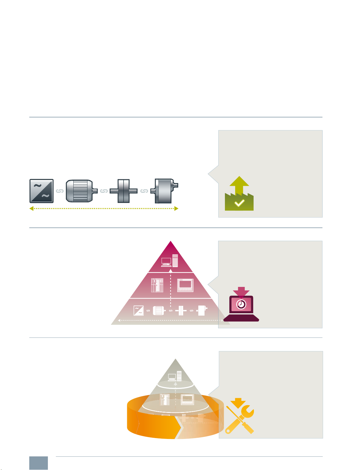
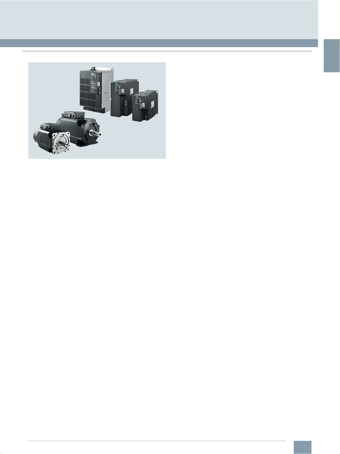
Integrated Drive Systems
Faster on the market and in the black with Integrated Drive Systems
Integrated Drive Systems are Siemens’ trendsetting answer to the high
degree of complexity that characterizes drive and automation technology
today. The world’s only true one-stop solution for entire drive systems is
characterized in particular by its threefold integration: Horizontal, vertical,
and lifecycle integration ensure that every drive system component fits
seamlessly into the whole system, into any automation environment, and
even into the entire lifecycle of a plant.
Horizontal integration
Integrated drive portfolio: The core elements of a fully integrated drive
portfolio are frequency converters, motors, couplings, and gear units.
At Siemens, they‘re all available from a single source. Perfectly integrated,
perfectly interacting. For all power and performance classes. As standard
solutions or fully customized. No other player in the market can offer a
comparable portfolio. Moreover, all Siemens drive components are
perfectly matched, so they are optimally interacting.
The outcome is an optimal workflow – from engineering all the way to
service that entails more productivity, increased efficiency, and better
availability. That’s how Integrated Drive Systems reduce time to market
and time to profit.
You can boost the avail ability
of your application or plant
to up to
*
99 %
*e.g., conveyor application
Vertical integration
Thanks to vertical integration, the complete drive train is
seamlessly integrated in the entire automation environment –
an important prerequisite for production with maximum
value added. Integrated Drive Systems are part of Totally
Integrated Automation (TIA), which means that they
are perfectly embedded into the system architecture
of the entire industrial production process. This
enables optimal processes through maximum
communication and control.
Lifecycle integration
Lifecycle integration adds the factor of time: Software and service
are available for the entire lifecycle of an Integrated Drive System.
That way, important optimization potential for maximum
productivity, increased efficiency, and highest availability
can be leveraged throughout the system’s lifecycle –
from planning, design, and engineering to operation,
maintenance, and all the way even to
modernization.
With Integrated Drive Systems, assets
become important success factors. They
ensure shorter time to market, maximum
productivity and efficiency in operation,
and shorter time to profit.
4
Siemens NC 81.1 · 2019
www.siemens.com/ids
Page 7
1
Introduction
© Siemens Industry, Inc. 2018
1/2 How to use this catalog
1/3 The system
1/4 SINUMERIK 808D ADVANCED
1/5 Feed and spindle drive solutions
1/6 MOTION-CONNECT
connection systems
Siemens NC 81.1 · 2019
Page 8
1
Introduction
How to use this catalog
■
Overview
© Siemens Industry, Inc. 2018
See chapter
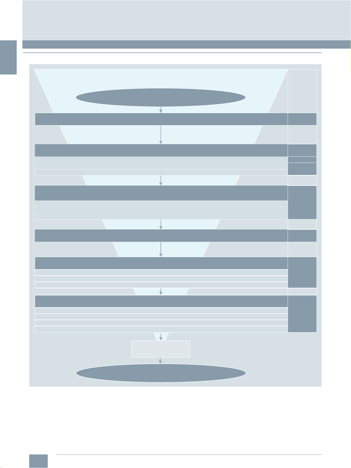
my CNC/drive/motor order list ?
Quick overview of the CNC/drive/motor system
SINUMERIK 808D ADVANCED
Overview of CNC functions
Technical specifications of CNC
Selection and ordering data of CNC
Feed and spindle drive solution SINAMICS V70/
SIMOTICS S-1FL6/SIMOTICS M-1PH1
Technical specifications of drive modules, motors and cables
Selection and ordering data of drive modules, motors and cables
Dimensional drawings of drive modules, motors and cables
Example packages to cross-check my order list
CNC accessories (MCP, handwheels, PLC I/O, power supply, direct spindle encoder)
Technical specifications of CNC accessories
Selection and ordering data of CNC accessories
Dimensional drawings of CNC accessories
1
2
3
3
3
4
1/2
SINUMERIK 808D on PC (training and offline programming system for PC)
Siemens NC 81.1 · 2019
Services and training
Material warranty and on-site service
System documentation
Training portfolio
Spindle solution
my CNC/drive/motor order list
5
G_NC01_EN_00796
!
Page 9
1
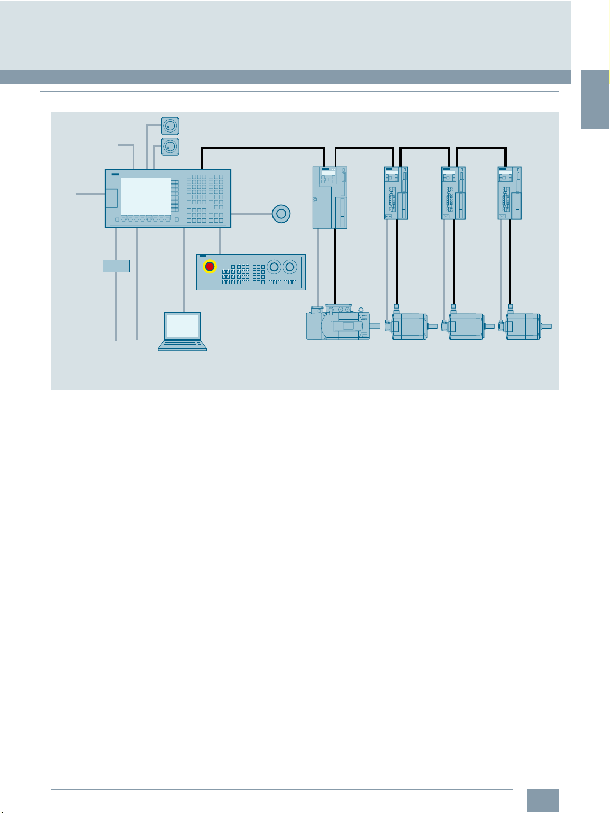
■
Overview
Digital tool probe
USB stick
Terminal strip
converter
Ribbon cable
© Siemens Industry, Inc. 2018
Introduction
The system
Handwheels
SINAMICS V70
1)
Ethernet/
factory
network
Drive bus
SINUMERIK 808D
ADVANCED
TTL
USB
SINUMERIK 808D MCP
spindle drive
Spindle
encoder
SINAMICS V70
servo drive
SINAMICS V70
servo drive
SINAMICS V70
servo drive
G_NC01_EN_00548b
PLC
process signals
1)
Only used for milling version
Notebook
SINUMERIK 808D ADVANCED system
SIMOTICS
M-1PH1
asynchronous
main spindle motor
SIMOTICS
S-1FL6
synchronous
feed motor
SIMOTICS
S-1FL6
synchronous
feed motor
SIMOTICS
S-1FL6
synchronous
feed motor
Siemens NC 81.1 · 2019
1/3
Page 10
1
© Siemens Industry, Inc. 2018
Introduction
SINUMERIK 808D ADVANCED
■
Overview
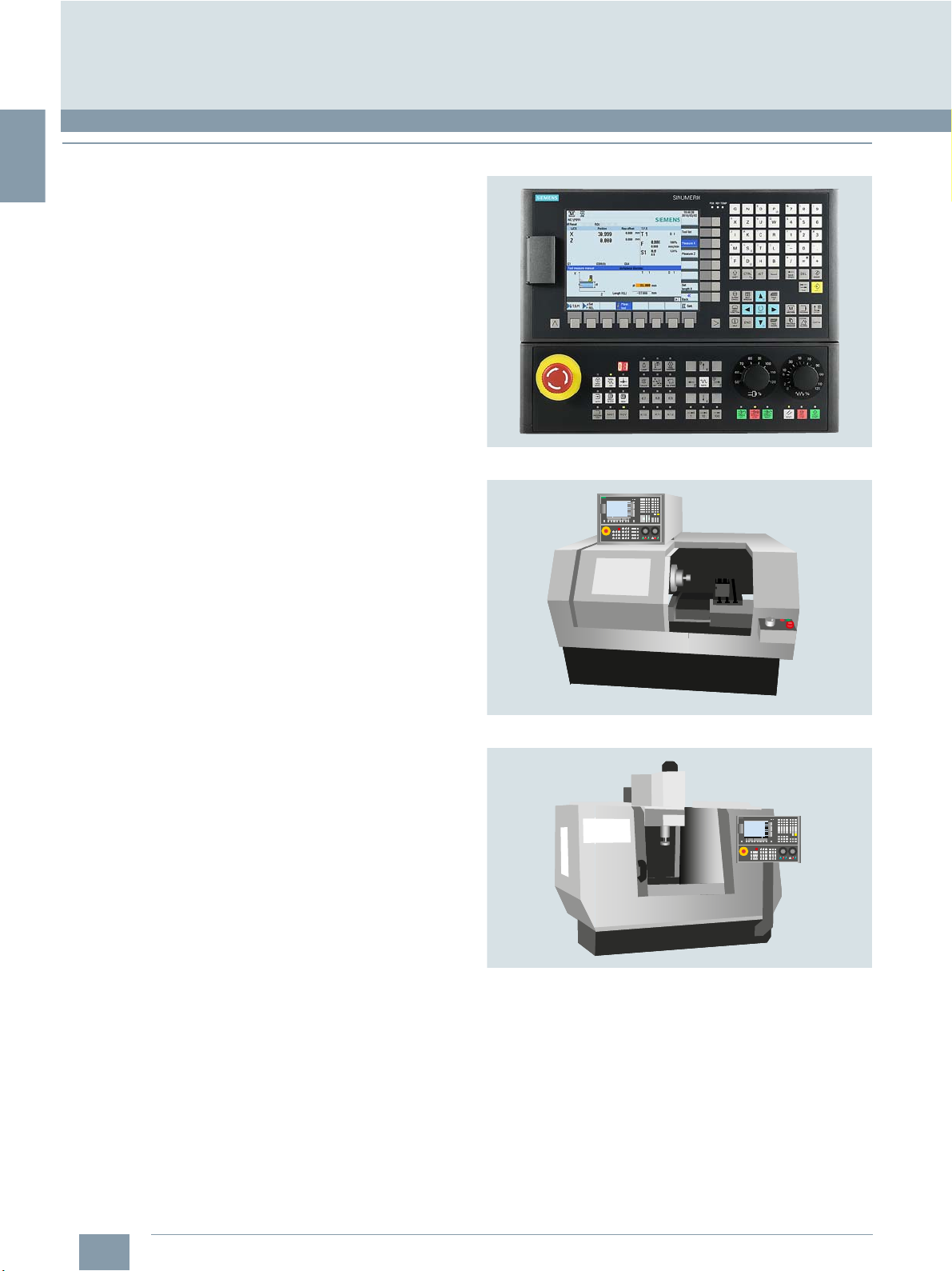
Small, robust, easy, simply smart
The operator-panel-based CNC SINUMERIK 808D ADVANCED
is extremely compact, rugged and very easy to maintain.
With variable software options and high-dynamic servo drive
systems, the SINUMERIK 808D ADVANCED system is offering
the latest CNC solution for high-performance basic machines.
Preconfigured for basic standard turning machines …
The SINUMERIK 808D ADVANCED T CNC is perfectly preconfigured to meet the requirements of modern standard turning
machines. Intelligent CNC features such as full servo controlled
rigid tapping or the flying switchover between spindle and C axis
enable most precise and fastest turning operation.
Perfectly preconfigured for:
7 SINUMERIK 808D ADVANCED T:
Up to 6 axes/spindles in one machining channel with/without
driven tool
7 Preconfigured system software for inclined bed fully
automated lathes and flat bed semi-automatic lathes
... and basic standard milling machines
The SINUMERIK 808D ADVANCED M CNC is perfectly preconfigured to meet the requirements of modern standard milling
machines.
7 SINUMERIK 808D ADVANCED M:
Up to 6 axes/spindles in one machining channel
7 Preconfigured system software for vertical machining centers
G_NC01_XX_00494
1/4
Siemens NC 81.1 · 2019
Page 11
1
■
Overview
© Siemens Industry, Inc. 2018
Introduction
Feed and spindle drive solutions
SINAMICS V70, SIMOTICS S-1FL6 and SIMOTICS M-1PH1
SINAMICS V70 servo drives, SIMOTICS S-1FL6 feed motors and
SIMOTICS M-1PH1 main spindle motors are designed for the
maximum cutting performance for the basic turning and milling
machine tool applications. The bus communication with the
SINUMERIK 808D ADVANCED CNC system, threefold overload
capacity and the 20 bit high-resolution absolute encoder installed in SIMOTICS S-1FL6 feed motors and SIMOTICS M-1PH1
main spindle motors allow to increase the precision and
efficiency of the machines.
With a robust design, SINAMICS V70 together with
SIMOTICS S-1FL6 feed motors and SIMOTICS M-1PH1 main
spindle motors are perfectly prepared for maximum availability
even in harsh environments.
Up to 36 months material warranty and on-site service
Siemens offers a standard material warranty and free
on-site service period of 24 months for the
SINUMERIK 808D ADVANCED and the associated components.
Warranty can be easily extended up to 36 months by end user
registration.
Moreover, Siemens ensures elimination of any defects on the
components free of cost on site during the warranty period.
Further information about the conditions and the scope of the
warranty and the on-site service can be found at:
www.siemens.com/automation/oss
Siemens NC 81.1 · 2019
1/5
Page 12
1
© Siemens Industry, Inc. 2018
Introduction
MOTION-CONNECT connection systems
■
Overview
MOTION-CONNECTION 300 connection system
The MOTION-CONNECT 300 cables in this catalog are suitable
for use with standard turning and milling machines.
The use of pre-assembled MOTION-CONNECT 300 cables ensures high quality and system-tested, problem-free operation.
Degree of protection of pre-assembled power and signal cables
and their extensions is IP65 when closed and connected unless
otherwise stated.
MOTION-CONNECT 300 cables are not suitable for outdoor use.
MOTION-CONNECT cables are approved for a maximum
horizontal traverse path of 5 m.
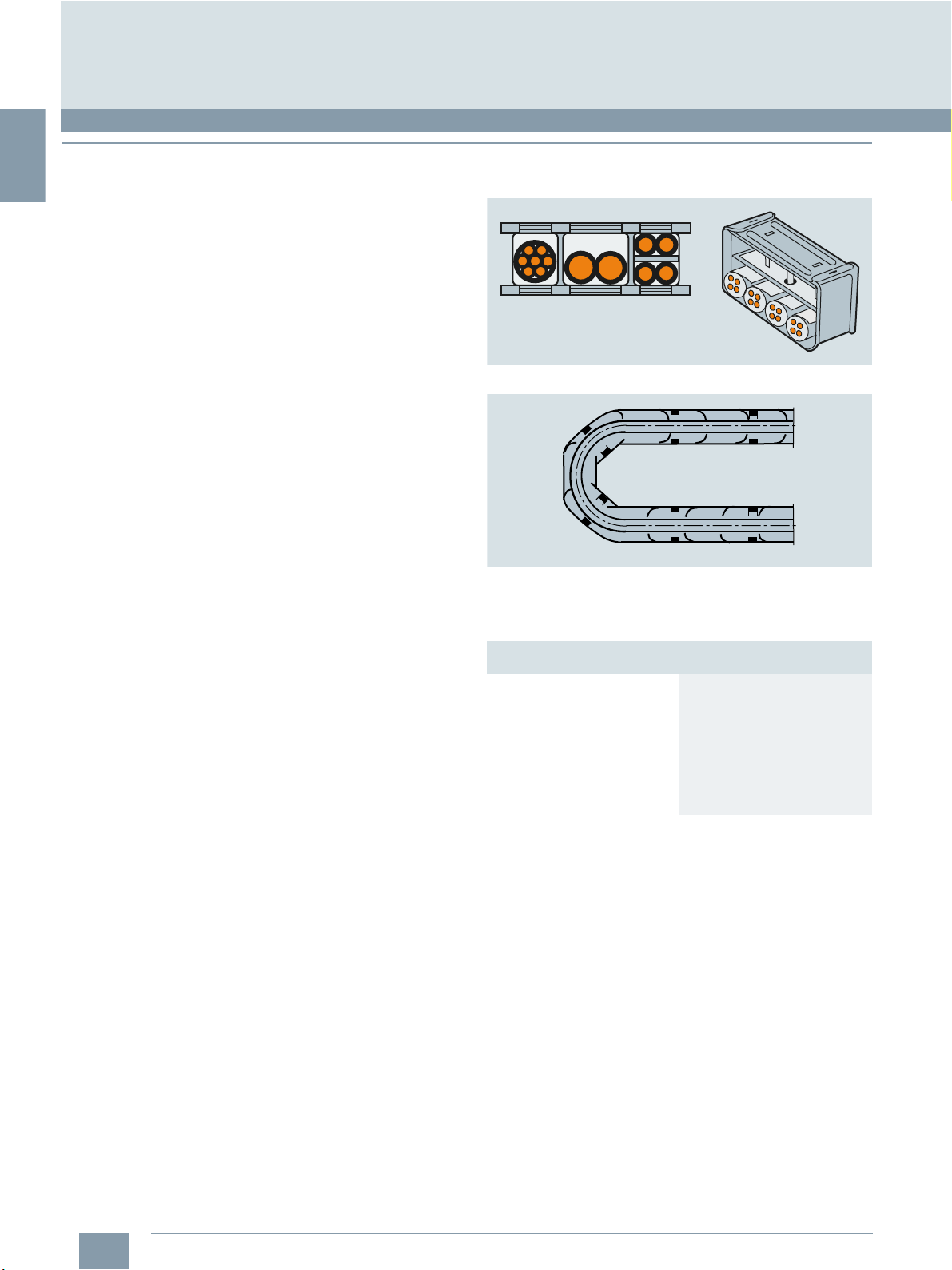
To maximize the service life of the cable carrier and cables,
cables in the carrier made from different materials must be
separated in the cable carrier using spacers. The spacers must
be filled evenly to ensure that the position of the cables does not
change during operation. The cables should be distributed as
symmetrically as possible according to their weights and dimensions. Cables with different outer diameters should be separated
by spacers as well.
When inserting pre-assembled cables into the cable carrier, do
not pull at the connector, as this may damage the strain relief or
cable clamping.
The cables must not be fixed in the cable carrier. They must be
freely movable.
The cables must be unwound without twisting.
G_NC01_XX_00455
G_NC01_XX_00290
The cables must be able to be moved without applying force,
specifically in the bending radii of the carrier. The specified
minimum bending radii must be adhered to.
The cable fixings must be attached at both ends at an appropriate distance from the end points of the moving parts in a dead
zone.
Cables must be installed in accordance with the instructions
supplied by the cable carrier manufacturer.
In case of vibration load and with horizontal or vertical cable
entries, we recommend that the cable is additionally fixed if
between the cable strain relief on the cable carrier and the
terminal at the motor part of the cable is hanging loose or is not
routed. To prevent machine vibrations being transmitted to the
connectors, the cable should be fixed at the moving part where
the motor is mounted.
Derating factors for power and signal cables
Ambient air temperature
°C (°F)
30 (86) 1.15
35 (95) 1.08
40 (104) 1.00
45 (113) 0.91
50 (122) 0.82
55 (131)
60 (140)
Derating factor
according to EN 60204-1 Table D.1
0.71
0.58
1/6
Siemens NC 81.1 · 2019
Page 13
2
Overview of functions
© Siemens Industry, Inc. 2018
2/2 SINUMERIK 808D ADVANCED
CNC controls
2/2 Control structure and configuration
2/2 Connectable drives
2/2 Connectable measuring systems
2/3 Operation
2/3 Axis functions
2/4 Spindle functions
2/4 Interpolations
2/4 Measuring functions
2/4 Motion-synchronous actions
2/5 Open Architecture
2/5 CNC programming language
2/6 Technology cycles
2/6 Canned cycles
2/7 Program and workpiece management
2/7 Programming support
2/7 Simulations
2/8 Operating modes
2/8 Tools
2/9 Communication and data management
2/10 HMI functions
2/10 Monitoring functions
2/10 Compensations
2/11 PLC area
2/12 Commissioning and serial production
2/12 Diagnostic functions
2/12 Service and maintenance
2/12 Training and offline programming
The functionality of the SINUMERIK 808D
ADVANCED CNCs PPU 15x and PPU 16x
complies with the export list restrictions.
Accordingly, these CNC controls do not
require official approval as a result of their
type in accordance with EU or German
law.
The following overview lists all the
functions that are available with
SINUMERIK 808D ADVANCED controls.
The information in the overview of
SINUMERIK 808D ADVANCED functions
is based on the following software
version:
CNC Software
SINUMERIK 808D
ADVANCED
PPU 15x.3/PPU 16x.3
Siemens NC 81.1 · 2019
version
4.90
Page 14
2
© Siemens Industry, Inc. 2018
Overview of functions
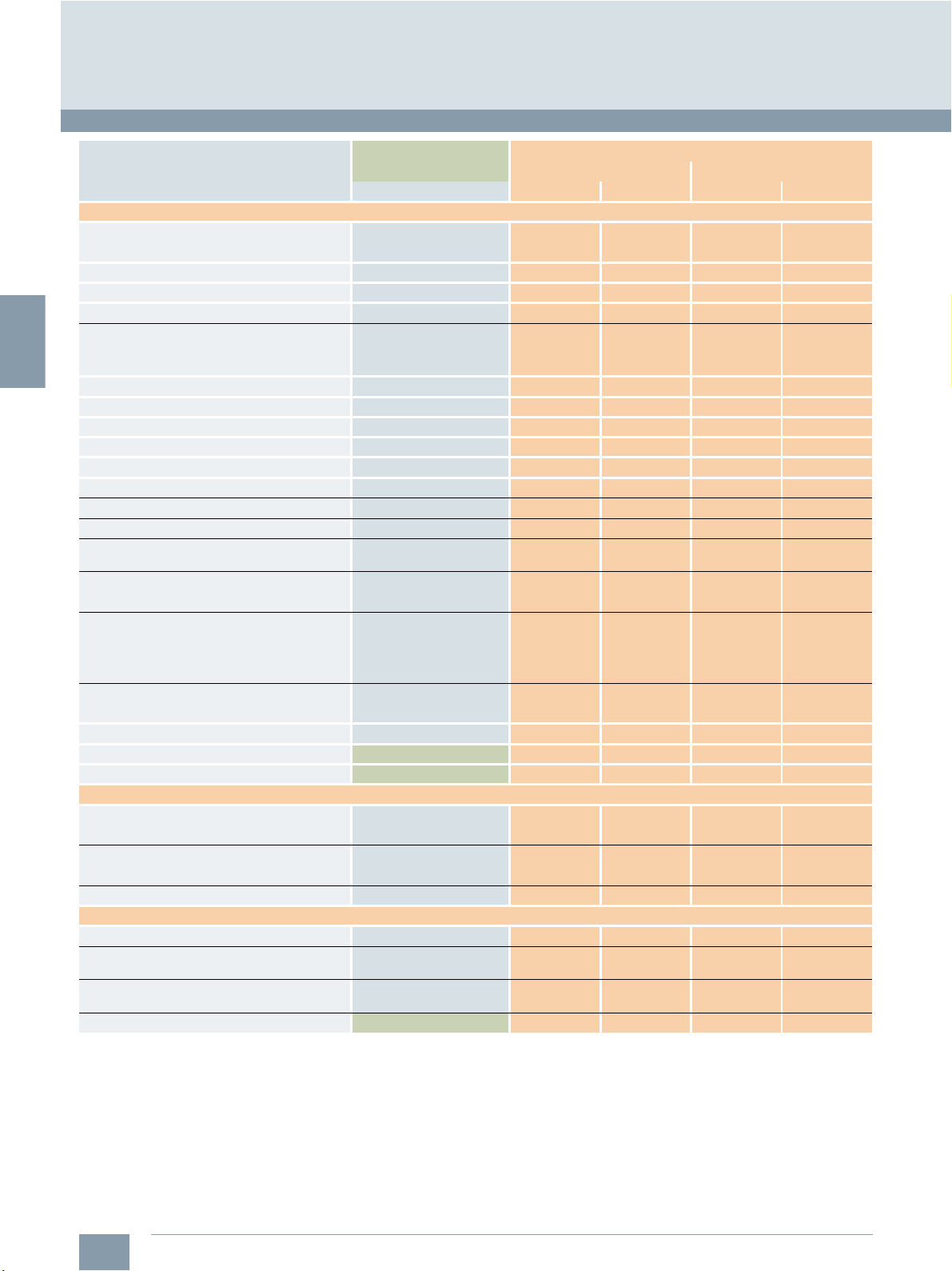
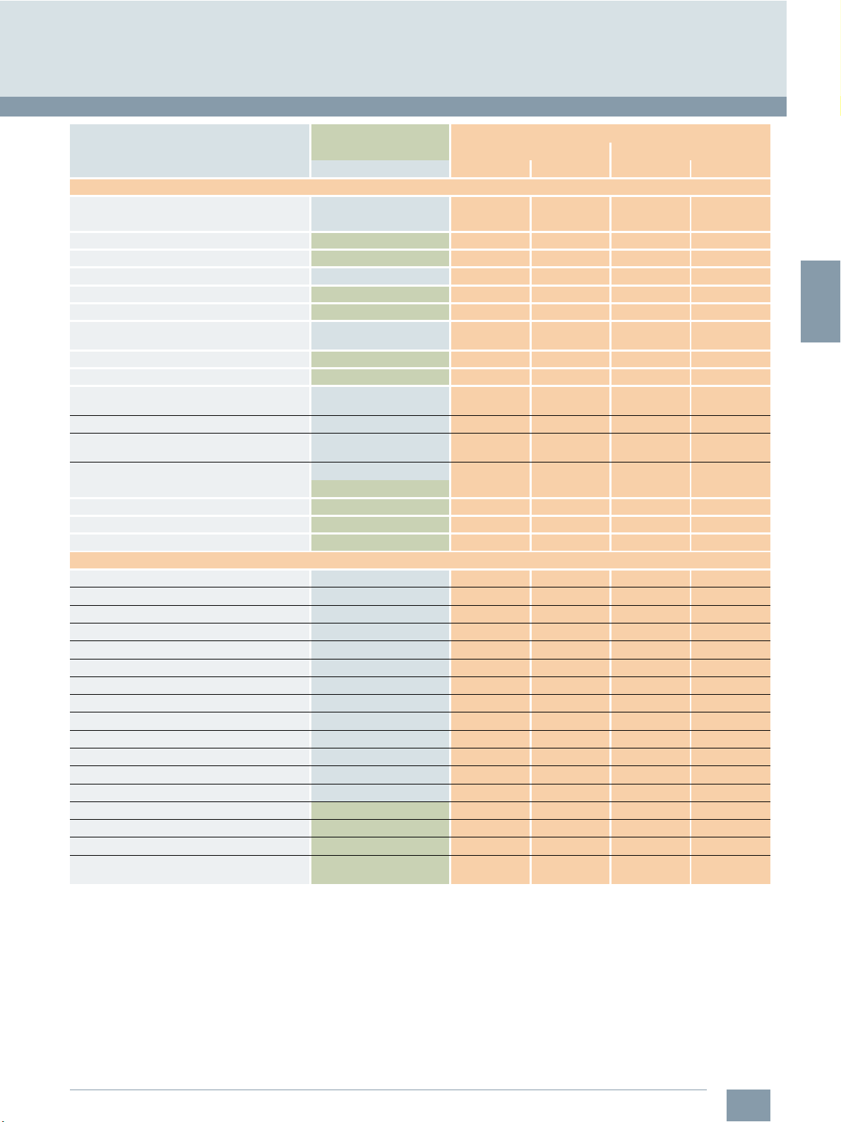
SINUMERIK 808D ADVANCED CNC controls
Control structure and configuration/Connectable drives/Connectable measuring systems
Basic version
O Option
– Not available
Control structure and configuration
Panel-based control system comprising:
• Compact operator panel
• CNC/PLC Control Unit
• Onboard digital PLC inputs/outputs
• CF card with system software Export version Tur ni ng Milling Tur ni ng Milling
SINUMERIK operator panel CNC:
• Operator panel layout
horizontal/vertical
• Color display 8.4" 8.4" 8.4" 8.4"
• Display resolution 800 × 600 800 × 600 800 × 600 800 × 600
• Integrated CNC keyboard with hard keys
• Specific CNC keyboard layout for Tur ni ng Milling Tur ni ng Milling
• Operator panel with Simplified Chinese layout
• Operator panel with English layout
SINUMERIK Operate BASIC
Quantity of bus interfaces for axis converter 1 1 1 1
Quantity of analog ±10 V interfaces for
spindle converter
Channels/mode groups MG:
• Maximum configuration 1 1 1 1
CNC user memory (buffered) for
CNC part programs
Axes/spindles:
• Basic quantity of axes/spindles 3 4 3 4
• Maximum configuration axes/spindles 4 4 6 6
• Axis/spindle, each additional 6FC5800-0AK70-0YB0 O – O O
• Additional 1 positioning axis/auxiliary spindle 6FC5800-0AK80-0YB0 O – O O
Connectable drives
Feed drives:
• SINAMICS V70 via bus interface O O O O
Spindles:
• Analog Drive Interface O O O O
SINAMICS V70 spindle via bus interface O O O O
Connectable measuring systems
Number of measuring systems per axis, max. 1 1 1 1
Encoder installed in
SIMOTICS S-1FL6 feed motors
Encoder installed in
SIMOTICS M-1PH1 main spindle motors
RS422 (TTL) direct incremental spindle encoder 6FX2001-2E... O O O O
Article No. SINUMERIK 808D ADVANCED
PPU 15x.3 PPU 16x.3
Note Turn in g Milling Tu rn in g Milling
/ / / /
1 1 1 1
The 1.25 MB memory is for
storing and editing the user
program. There is another
500 MB memory for NC
program storage.
1.25 MB 1.25 MB 1.25 MB 1.25 MB
2/2
Siemens NC 81.1 · 2019
Page 15
2
© Siemens Industry, Inc. 2018
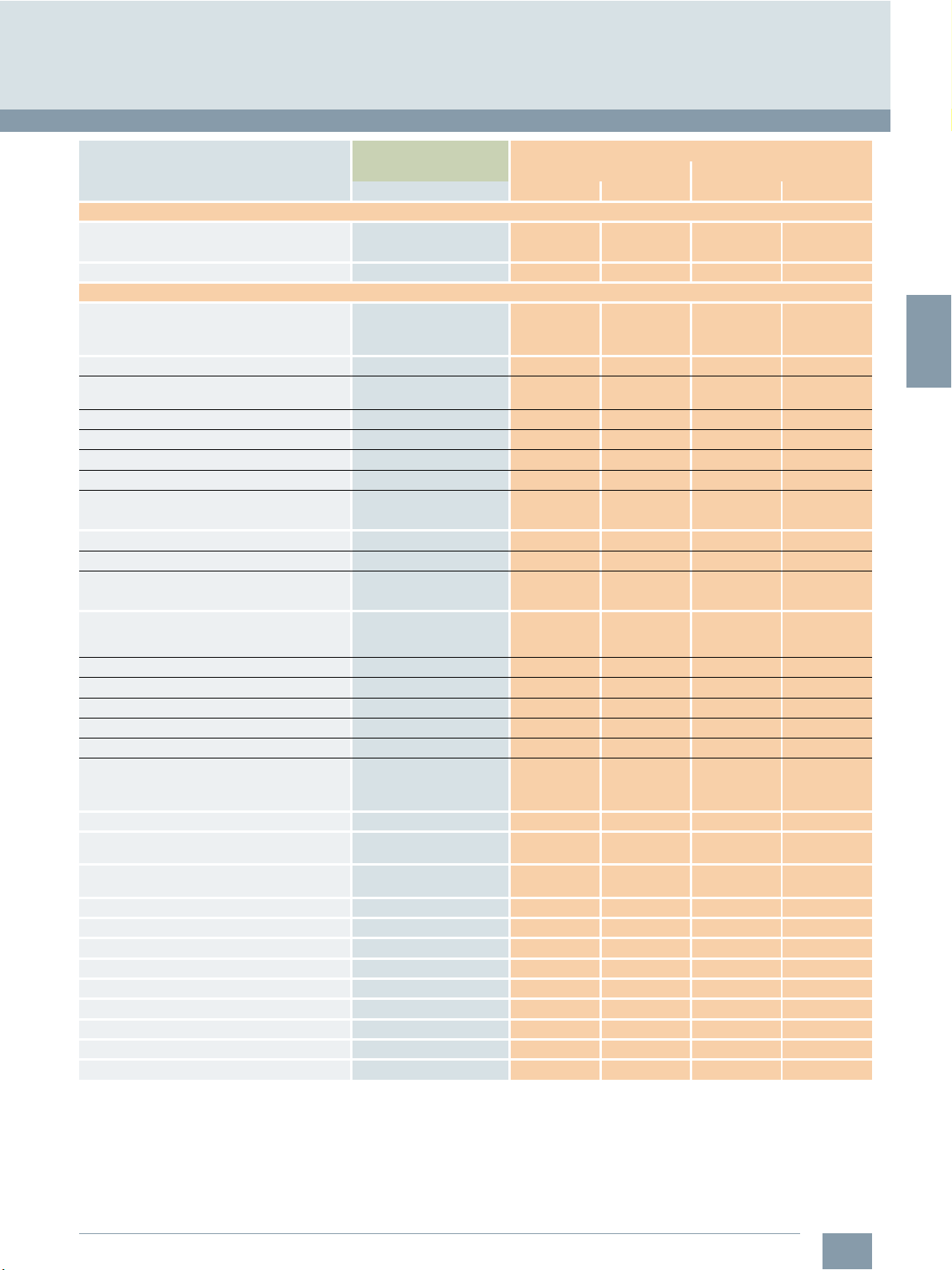
SINUMERIK 808D ADVANCED CNC controls
Overview of functions
Operation/Axis functions
Basic version
O Option
– Not available
Operation
Machine Control Panel:
• SINUMERIK 808D MCP horizontal:
- English layout 6FC5303-0AF35-0AA0 O O O O
- Simplified Chinese layout 6FC5303-0AF35-0CA0 O O O O
• SINUMERIK 808D MCP vertical:
- English layout 6FC5303-0AF35-2AA0 O O O O
- Simplified Chinese layout 6FC5303-0AF35-2CA0 O O O O
• SINUMERIK 808D MCP vertical:
with handwheel slot
- English layout 6FC5303-0AF35-3AA0 O O O O
- Simplified Chinese layout 6FC5303-0AF35-3CA0 O O O O
• 3rd-party MCP via onboard digital
PLC inputs/outputs
Number of digital tool probes, max. – 1 – 1
Number of electronic handwheels
RS422 5 V DC, max.
Electronic handwheels 5 V DC:
• With 120 mm × 120 mm front panel 6FC9320-5DB01 O O O O
• With 76.2 mm × 76.2 mm front panel 6FC9320-5DC01 O O O O
• Without front panel, without setting wheel 6FC9320-5DF01 O O O O
• Without front panel, with setting wheel 6FC9320-5DM00 O O O O
Axis functions
Feedrate override 0 ... 200 % 0 ... 200 % 0 ... 200 % 0 ... 200 %
Feedrate override axis-specific 0 ... 200 % 0 ... 200 % 0 ... 200 % 0 ... 200 %
Traversing range decades ± 9 ± 9 ± 9 ± 9
Rotary axis, turning endlessly
Velocity, max. 300 m/s 300 m/s 300 m/s 300 m/s
Acceleration with jerk limitation
Programmable acceleration
Feedrate interpolation
Separate path feed for corners and chamfers
Velocity-dependent feed forwad control
Friction compensation
Auto Servo Tuning AST
Direct Servo Control DSC
TRANSMIT/TRACYL Transformation without Y axis 6FC5800-0AS50-0YB0 – – O O
Pair of synchronized axes (gantry axes), basic 6FC5800-0AS51-0YB0 – – O O
Contour handwheel 6FC5800-0AM08-0YB0 O O O O
Generic coupling, CP-Basic, e.g. multi-edge
turning
Article No. SINUMERIK 808D ADVANCED
PPU 15x.3 PPU 16x.3
Note Turn in g Milling Tu rn in g Milling
O O O O
2 2 2 2
6FC5800-0AM72-0YB0 – – O –
Siemens NC 81.1 · 2019
2/3
Page 16

2
© Siemens Industry, Inc. 2018
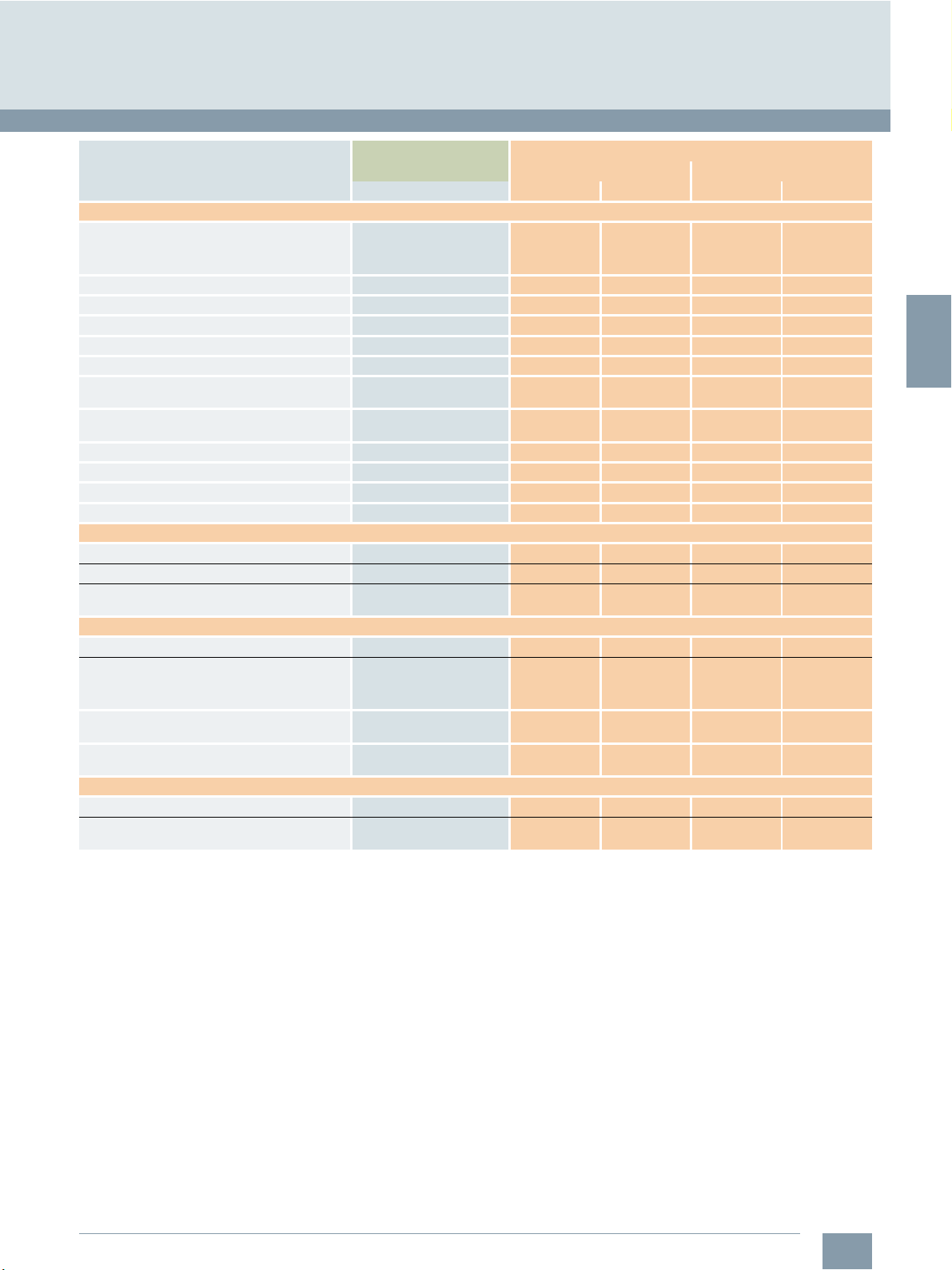
Overview of functions
SINUMERIK 808D ADVANCED CNC controls
Spindle functions/Interpolations/Measuring functions/Motion-synchronous actions
Basic version
O Option
– Not available
Spindle functions
Spindle speed, analog
Spindle speed, max. programmable value range
(display ± 999999999.9999)
Spindle override 0 ... 200 % 0 ... 200 % 0 ... 200 % 0 ... 200 %
Gear stages 5 5 5 5
Intermediate gear
Automatic gear stage selection
Oriented spindle stop Requires direct spindle
Spindle speed limitation min./max.
Constant cutting rate
Spindle control via PLC (positioning, oscillation)
Changeover to axis mode Requires servo spindle and
Axis synchronization on-the-fly Requires servo spindle and
Thread run-in and run-out programmable
Thread cutting with constant or variable pitch
Tapping with compensating chuck/rigid tapping Requires servo spindle and
Interpolations
Linear interpolation axes, max. 3 3 3 4
Circle via center point and end point
Circle via interpolation point
Helical interpolation
Continuous-path mode with programmable
rounding clearance
Advanced Surface look ahead, velocity control
and CNC block compression
High-speed setting cycle CYCLE832 – – –
Look ahead (number of blocks) 1 50 1 150
Measuring functions
Measuring in JOG:
• Number of probes (switching)
with/without deletion of distance-to-go
Motion-synchronous actions
CNC inputs/outputs, high-speed:
• Digital inputs CNC onboard 3 3 3 3
- Digital inputs cycle time 0.2 ms 0.2 ms 0.2 ms 0.2 ms
• Digital outputs CNC onboard 1 1 1 1
- Digital outputs cycle time 0.3 ms 0.3 ms 0.3 ms 0.3 ms
Synchronized actions and high-speed auxiliary
function output incl. 3 synchronous functions
Positioning axes and spindles via
synchronized actions (command axes)
Article No. SINUMERIK 808D ADVANCED
PPU 15x.3 PPU 16x.3
Note Turn in g Milling Tu rn in g Milling
encoder.
direct encoder.
direct encoder.
direct encoder.
-4
106 ... 10
– – –
– 1 – 1
106 ... 10
-4
106 ... 10
-4
106 ... 10
-4
2/4
Siemens NC 81.1 · 2019
Page 17
2
© Siemens Industry, Inc. 2018
SINUMERIK 808D ADVANCED CNC controls
Overview of functions
Open Architecture/CNC programming language
Basic version
O Option
– Not available
Open Architecture
Customizable HMI:
• Customizable screens in the HMI
• Input screens for customized user cycles
CNC programming language
Programming methods:
• SINUMERIK style programming language
(DIN 66025 and high-level language expansion)
• ISO code
Main program call from main program and
subroutine
Subprogram levels, max. 11 11 11 11
Number of subprogram passes 9999 9999 9999 9999
Number of levels for skip blocks 1 1 1 1
Polar coordinates
Dimensions metric/inch, changeover:
• Manually
•Via program
Inverse-time feedrate
Auxiliary function output:
• Via M word, max. programmable value range INT 231-1 INT 231-1 INT 231-1 INT 231-1
• Via H word, max. programmable value range
REAL ± 3.4028 ex 38
(display ± 999999999.9999)
Basic frames, max. number 1 1 1 1
Settable offsets, max. number 6 6 32 32
Work offsets, programmable (frames)
Global and local user data
Global program user data
SINUMERIK high-level CNC language with:
• Frame concept
TRANS/ROT/SCALE/MIRROR
• User variables, configurable
• Predefined user variables
(arithmetic parameters)
• Predefined user variables
(arithmetic parameters), configurable
• Read/write system variables
• Indirect programming
• Program jumps and branches
• Arithmetic and trigonometric functions
• Compare operations and logic combinations
• Macro techniques
• Control structures IF-ELSE-ENDIF
• Control structures WHILE, FOR, REPEAT, LOOP
• STRING functions
Article No. SINUMERIK 808D ADVANCED
PPU 15x.3 PPU 16x.3
Note Turn in g Milling Tu rn in g Milling
INT -231 ...
-1
231
INT -231 ...
-1
231
INT -231 ...
-1
231
INT -231 ...
-1
231
Siemens NC 81.1 · 2019
2/5
Page 18

2
© Siemens Industry, Inc. 2018
Overview of functions
SINUMERIK 808D ADVANCED CNC controls
Technology cycles/Canned cycles
Basic version
O Option
– Not available
Technology cycles
Technology cycles for SINUMERIK style
programming language:
• Drilling, centering – CYCLE81
• Drilling, counterboring – CYCLE82
• Deep-hole drilling – CYCLE83
• Rigid tapping – CYCLE84
• Tapping with compensating chuck – CYCLE840
• Reaming 1 – CYCLE85
• Boring – CYCLE86
• Position pattern: Row of holes – HOLES1 – –
• Position pattern: Circle of holes – HOLES2 – –
• Cutoff - CYCLE92 – –
• Groove – CYCLE93 – –
• Undercut (forms E and F according to DIN) –
CYCLE94
• Contour cutting with relief cut – CYCLE95 – –
• Thread undercut – CYCLE96 – –
• Thread chaining – CYCLE98 – –
• Thread cutting – CYCLE99 – –
• Face milling – CYCLE71 – –
• Contour milling – CYCLE72 – –
• Milling a rectangular spigot – CYCLE76 – –
• Milling a circular spigot – CYCLE77 – –
• Long holes located on a circle – LONGHOLE – –
• Slots on a circle – SLOT1 – –
• Circumferential slot – SLOT2 – –
• Milling a rectangular pocket – POCKET3 – –
• Milling a circular pocket – POCKET4 – –
• Thread milling – CYCLE90 – –
• High-speed settings – CYCLE832 – –
Canned cycles
Canned cycles for ISO code milling:
• High-speed deep hole drilling cycle with chip
breakage (G73)
• Drilling a left-hand thread without any
compensating chuck cycle (G74)
• Fine drilling cycle (G76) – –
• Deselection of a fixed cycle (G80) – –
• Drilling cycle, counterboring (G81) – –
• Countersink drilling cycle (G82) – –
• Deep hole drilling cycle with chip removal (G83) – –
• Drilling a right-hand thread without any
compensating chuck cycle (G84)
• Boring cycle (G85) – –
• Boring cycle, retraction with G00 (G86) – –
• Boring cycle, reverse countersinking (G87) – –
• Boring cycle, retraction with machining feedrate
(G89)
Article No. SINUMERIK 808D ADVANCED
PPU 15x.3 PPU 16x.3
Note Turn in g Milling Tu rn in g Milling
– –
– –
– –
– –
– –
2/6
Siemens NC 81.1 · 2019
Page 19
2
© Siemens Industry, Inc. 2018
Overview of functions
SINUMERIK 808D ADVANCED CNC controls
Canned cycles/Program and workpiece management/Programming support/Simulations
Basic version
O Option
– Not available
Canned cycles (continued)
Canned cycles for ISO code turning
(G code system A):
• Thread cutting with constant lead (G32) – –
• Thread cutting with variable lead (G34) – –
• Finishing cycle (G70) – –
• Stock removal cycle longitudinal axis (G71) – –
• Stock removal cycle transverse axis (G72) – –
• Closed cutting cycle (G73) – –
• Multiple repetitive grooving cycles in the
longitudinal axis (G74)
• Deep hole drilling and recessing in
facing axis (G75)
• Multiple thread cutting (G76) – –
• Axial cutting (G90) – –
• Thread cutting (G92) – –
• Radial cutting (G94) – –
Program and workpiece management
Part programs on PPU, max. number 255 255 255 255
Readable part program names
Sub-folders for part programs with
readable names
Programming support
Background editing
Program editor:
• Full screen CNC editor with cut, copy and
paste functionality
• Programming support programGUIDE BASIC
for SINUMERIK technology cycles
• Contour computer with programming
graphics/free contour input (contour calculator)
Simulations
2D simulation
Real-time simulation of current machining
operation
Article No. SINUMERIK 808D ADVANCED
PPU 15x.3 PPU 16x.3
Note Turn in g Milling Tu rn in g Milling
– –
– –
Siemens NC 81.1 · 2019
2/7
Page 20
2
© Siemens Industry, Inc. 2018
Overview of functions
SINUMERIK 808D ADVANCED CNC controls
Operating modes/Tools
Basic version
O Option
– Not available
Operating modes
Manual Machine plus for manual controlled
semi-CNC lathes
JOG:
• T, S, M screen for quick activation of machine
functions
• Face milling cycle for workpiece preparation – –
• Handwheel selection
• Switchover: inch/metric
• Manual measurement of work offset
• Manual measurement of tool offset
• Semi-automatic tool measurement with
tool probe
MDI:
• Input in text editor
Automatic:
• Execution from memory stick connected to
USB interface on operator panel front
• Program control
(dry-run feed, block skip etc.)
• Program editing
• Block search with/without calculation
Repos (repositioning on the contour):
• With operator command/semi-automatically
• Program-controlled
Preset:
• Set actual value
Too ls
Tools/cutting edges, max. 64/128 64/128 64/128 64/128
Tool types:
• Turning – –
• Drilling
• Milling
Tool radius compensations in plane:
• With approach and retract strategies
• With transition circle/ellipse on outer edges
Tool offset selection via T and D numbers
Look-ahead detection of contour violations
Article No. SINUMERIK 808D ADVANCED
PPU 15x.3 PPU 16x.3
Note Turn in g Milling Tu rn in g Milling
6FC5800-0AP07-0YB0 O – O –
– –
2/8
Siemens NC 81.1 · 2019
Page 21

2
© Siemens Industry, Inc. 2018
SINUMERIK 808D ADVANCED CNC controls
Overview of functions
Communication and data management
Basic version
O Option
– Not available
Communication and data management
USB interface on panel front for memory stick
and USB PC keyboard:
• Transfer of:
- Machine and setting data
-PLC data
- Compensation data
- Tool and work offset data
- R parameter
-HMI data
- User cycles
- Part programs
- PLC program (*.pte)
• Execute part program
Ethernet interface:
• Transfer of:
- Machine and setting data
-PLC data
- Compensation data
- Tool and work offset data
- R parameter
-HMI data
- User cycles
- Part programs
• Execute part program
• Part program send/receive
• PLC program upload/download
• PLC status monitoring
Article No. SINUMERIK 808D ADVANCED
PPU 15x.3 PPU 16x.3
Note Turn in g Milling Tu rn in g Milling
Siemens NC 81.1 · 2019
2/9
Page 22
2
© Siemens Industry, Inc. 2018
Overview of functions
SINUMERIK 808D ADVANCED CNC controls
HMI functions/Monitoring functions/Compensations
Basic version
O Option
– Not available
HMI functions
CNC lock function 6FC5800-0AS71-0YB0 O O O O
Lock MyCycles 6FC5800-0AP54-0YB0 O O O O
SINUMERIK 808D startGUIDE:
• Startup assistant
Built-in graphical interactive assistant for
1st commissioning of machines with
SINUMERIK 808D
• Series startup assistant
Built-in graphical interactive assistant for
the series production of machines with
SINUMERIK 808D
• Sales assistant
Built-in viewer for bitmaps with sales arguments
for SINUMERIK 808D, extendable by customerspecific sales arguments for the machine
Online help for programming, alarms and
machine data
CNC program messages
Screen saver
Access protection level support
Chinese input method editor for part program
names, sub-directory names and CNC comments
Operating software languages:
• Chinese Simplified, Czech, English, French,
German, Italian, Korean, Polish, Portuguese,
Russian, Spanish, Turkish, Hungarian
• Language switchover online
Monitoring functions
Working area limitation
Limit switch monitoring
Software and hardware limit switches
Position monitoring
Standstill (zero-speed) monitoring
Clamping monitoring
Contour monitoring
Axis limitation from the PLC
Spindle speed limitation
Compensations
Backlash compensation
Leadscrew error compensation
Bidirectional leadscrew error compensation 6FC5800-0AM54-0YB0 O O O O
Article No. SINUMERIK 808D ADVANCED
PPU 15x.3 PPU 16x.3
Note Turn in g Milling Tu rn in g Milling
2/10
Siemens NC 81.1 · 2019
Page 23
2
© Siemens Industry, Inc. 2018
SINUMERIK 808D ADVANCED CNC controls
Overview of functions
PLC area
Basic version
O Option
– Not available
PLC area
Integrated PLC
Style of PLC program:
• Prepared and ready to run PLC program
on board
• Fully customized PLC programs by
offline PLC programming tool
Fixed cycle time for PLC 12 ms 12 ms 12 ms 12 ms
Maximum number of ladder steps 6000 6000 6000 6000
PLC programming language:
• LAD ladder diagram
Offline PLC programming tool 6FC5811-0CY00-0YA8 O O O O
PLC Ladder Viewer on PPU
PLC I/O:
• On-board digital PLC: Connection via screw-clamp
- Inputs 24 V 24 24 24 24
- Outputs 24 V, 0.2 A 16 16 16 16
• On-board digital PLC: Connection via 50-pole
- Inputs 24 V 48 48 48 48
- Outputs 24 V, 0.2 A 32 32 32 32
Connection via 50-pole ribbon cable
connector to PPU:
• Terminal strip converter 6EP5406-5AA00 O O O O
• Cable set 6EP5306-5BG00 O O O O
PLC alarms/messages, max. number 128 128 128 128
Bit memories, number 256 bytes 256 bytes 256 bytes 256 bytes
Timers, number 64 64 64 64
Counters, number 64 64 64 64
Subroutines 64 64 64 64
User machine data for configuring the
PLC user program
Article No. SINUMERIK 808D ADVANCED
PPU 15x.3 PPU 16x.3
Note Turn in g Milling Tu rn in g Milling
On toolbox DVD-ROM
connector on PPU.
ribbon cable connector.
Siemens NC 81.1 · 2019
2/11
Page 24
2
© Siemens Industry, Inc. 2018
Overview of functions
SINUMERIK 808D ADVANCED CNC controls
Commissioning and serial production/Diagnostic functions/Service and maintenance/Training and offline programming
Basic version
O Option
– Not available
Commissioning and serial production
SINUMERIK 808D startGUIDE
• Startup assistant
Built-in graphical interactive assistant for
1st commissioning of machines with
SINUMERIK 808D controls
• Series startup assistant
Built-in graphical interactive assistant for the
series production of machines with
SINUMERIK 808D controls
Backup/restore of system software via
USB memory stick
Cloning of serial startup files for serial production
via USB memory stick
SINUMERIK 808D family toolbox with: 6FC5811-0CY00-0YA8 O O O O
• Offline PLC programming tool O O O O
• Sample PLC program O O O O
• MCP strip template O O O O
• MCP icon library O O O O
• User manuals O O O O
• Access My Machine AMM
Diagnostic functions
Alarms and messages
Action log can be activated for diagnostic
purposes
PLC status
LAD display
Service and maintenance
Integrated service planner for monitoring of
service intervals
One touch system backup
(Ctrl + S)
CNC memory buffering via battery
Training and offline programming
SINUMERIK 808D on PC 6FC5870-0YC40-0YT0 O O O O
Article No. SINUMERIK 808D ADVANCED
PPU 15x.3 PPU 16x.3
Note Turn in g Milling Tu rn in g Milling
On toolbox DVD-ROM.
Free download of trial
version from:
www.cnc4you.com
2/12
Siemens NC 81.1 · 2019
Page 25
3
SINUMERIK 808D ADVANCED system
© Siemens Industry, Inc. 2018
3/2
3/2
3/5 Operator components
3/5 SINUMERIK 808D MCP
3/8 Feed axis solutions
3/8 SINAMICS V70 servo drive
3/12 SIMOTICS S-1FL6 feed motor
3/16 Spindle solutions
3/16 SINAMICS V70 spindle drive
3/20 SIMOTICS M-1PH1 main spindle motor
3/26 MOTION-CONNECT connection systems
3/26 MOTION-CONNECT cables for
3/29 MOTION-CONNECT cables for
3/31 MOTION-CONNECT cables for
3/33 Sample packages
3/33 Sample package for Turning with
3/34 Sample package for Milling with
CNC control
SINUMERIK 808D ADVANCED
PPU 15x.3/PPU 16x.3
horizontal/vertical
SINUMERIK 808D ADVANCED
SINAMICS V70 servo drive
SINAMICS V70 spindle drive
SINUMERIK 808D ADVANCED T
SINUMERIK 808D ADVANCED M
Siemens NC 81.1 · 2019
Page 26

3
1)
Only for turning
2)
Only for PPU 16x.3 milling
3)
Up to 4 axes/spindle for PPU 15x.3
4)
Only for milling
© Siemens Industry, Inc. 2018
SINUMERIK 808D ADVANCED system
CNC control
SINUMERIK 808D ADVANCED PPU 15x.3/PPU 16x.3
■
Overview
SINUMERIK 808D ADVANCED PPU 151.3/PPU 161.3 horizontal
SINUMERIK 808D ADVANCED PPU 150.3/PPU 160.3 vertical
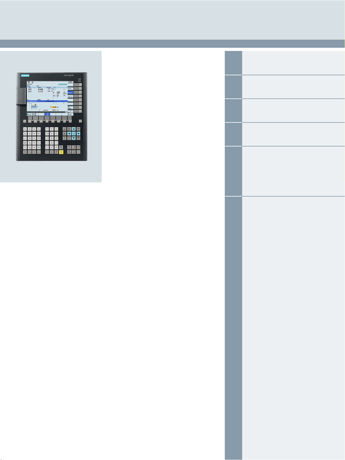
The SINUMERIK 808D ADVANCED PPU 15x.3/PPU 16x.3 is an
operator-panel-based CNC, preconfigured for use in modern
basic standard turning and milling machines.
There are two variants of SINUMERIK 808D ADVANCED PPU's –
PPU 15x.3 and PPU 16x.3 – with same appearance and different
functionalities. The differences are described between PPU
15x.3 and PPU 16x.3 in chapter 2 - Overview of functions.
■
Benefits
7 Compact, rugged, and maintenance-friendly operator-panel
CNC
7 Actual position feedback to CNC
7 Intelligent clamp mounting without drilling holes into the
cabinet
7 Minimum commissioning efforts due to plug and play machine
control panel connected via USB interface
7 Direct commissioning on HMI for feed drives and automatic
servo tuning (AST)
7 Maximum performance and accuracy due to most modern
CNC features
7 SINUMERIK 808D startGUIDE: assists all process steps of the
machine – from engineering to production, from sales to operation and programming at the push of a button
7 SINUMERIK Operate BASIC: maximum operator convenience
similar to SINUMERIK 828D and SINUMERIK 840D sl
7 SINUMERIK programGUIDE BASIC: wide range of
technology cycles for turning, milling and drilling with
graphical input screens
7 Manual Machine plus: easy semi-automatic machining with
handwheel controlled flat-bed lathes
7 Fast data transmission via USB stick and high-speed Ethernet
1)
interface
7 More software options can cover more applications and
enhance the machine performance
7 Maximum performance and accuracy due to the Advanced
Surface function
■
Function
2)
• 2 operator panel variants for horizontal and vertical operator
panel housings
• IP65 protection for CNC front panel and machine control panel
• Integrated CNC keyboard with mechanical keys
• Simplified Chinese or English panel layout
• 8.4” color LCD display
• USB user interface on the operator panel front
• Drive bus interface for feed drives and spindle
• Analog ±10 V interface for spindle drive
• Data buffering without battery
• Pre-configured system software for turning and milling
technologies
• Up to 6 axes/spindles
3)
• Automatic servo tuning AST
• Ethernet interface for commissioning and data transfer
• Graphically guided SINUMERIK CNC programming and
standard ISO-code programming with canned cycles
• Graphical CNC simulation
• Integrated contour computer
• Integrated PLC based on the SIMATIC S7-200 command set
with ladder logic programming
• Integrated/distributed PLC I/O concept with 72 digital PLC
inputs and 48 digital PLC outputs
• CNC options subject to license
• Customized user screens
• Machine maintenance tasks are accomplished by integrated
service planner
■
Integration
The following components can be connected to the
SINUMERIK 808D ADVANCED PPU 15x.3/PPU 16x.3:
• Up to 2 electronic handwheels
• Up to 72 digital PLC inputs and 48 digital PLC outputs
• 1 TTL direct spindle encoder
• SINUMERIK 808D MCP via USB interface
• SINAMICS V70 drive system for feed axes and spindle
• Spindle drives via ±10 V analog output
• PC via Ethernet interface
• 1 digital tool probe
4)
3/2
Siemens NC 81.1 · 2019
Page 27

3
1)
Only for PPU 15x.3 turning and PPU 16x.3
2)
Only for turning
3)
Only for PPU 16x.3
4)
Only for PPU16x.3 turning
© Siemens Industry, Inc. 2018
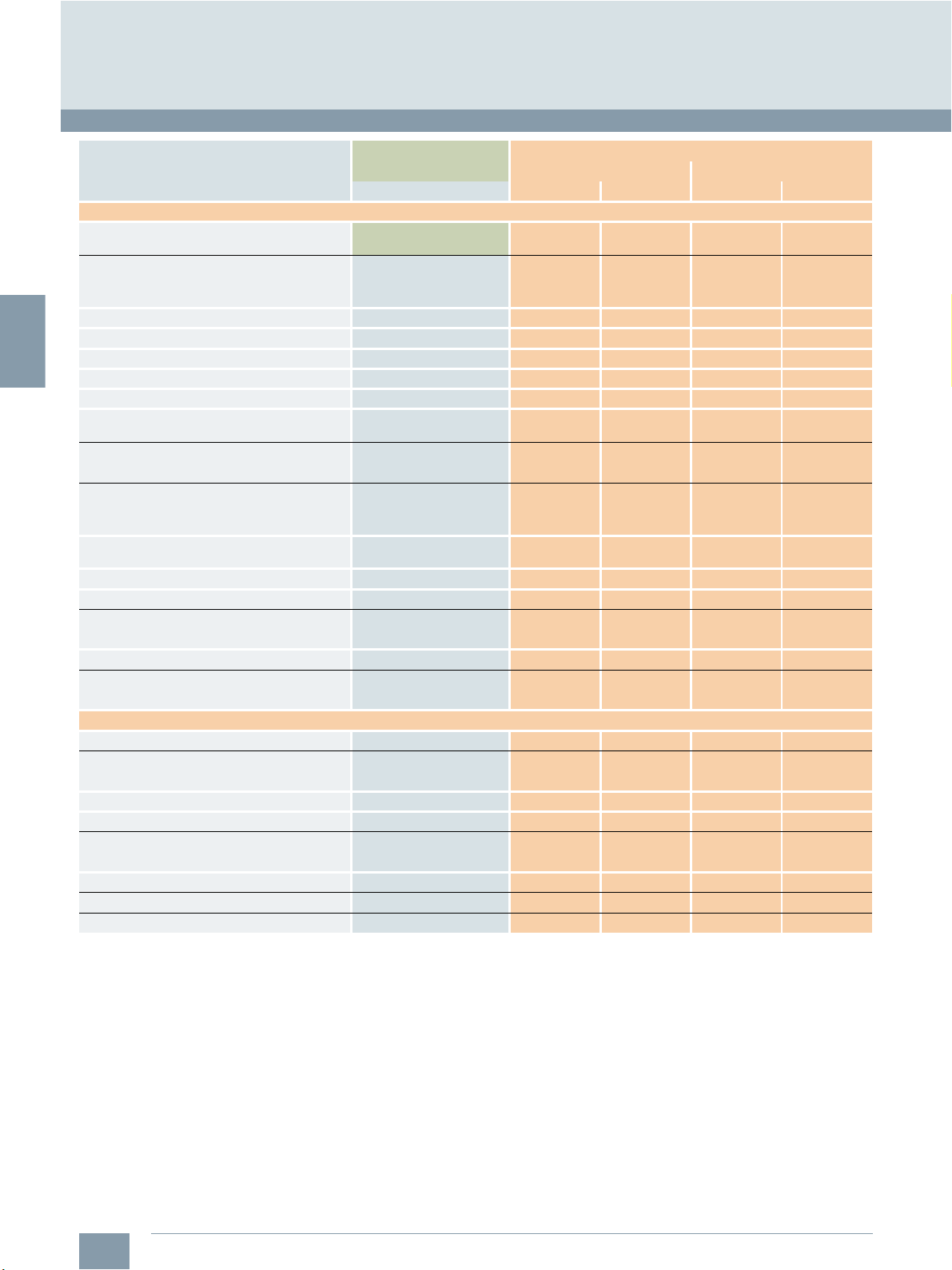
SINUMERIK 808D ADVANCED system
SINUMERIK 808D ADVANCED PPU 15x.3/PPU 16x.3
■
Technical specifications
Article No. 6FC5370-.B.03-0.A0 6FC5370-.A.03-0.A0
Product name SINUMERIK 808D ADVANCED
PPU 150.3/PPU 160.3 vertical
Supply voltage at DC 24 V + 20 %/- 15 %
Active power consumption maximum 50 W
Buffering time in the event of power failure 3 ms (20 ms with SITOP smart power supply)
Degree of protection
• Front, with the front flap closed IP65
•Rear IP20
Relative humidity at 25 °C, during
• storage and transport 5…95%
•operation 5…90%
Ambient temperature, during
• storage and transport -20 ... +60 °C
•operation
-front 0...45°C
-rear 0...50°C
Width 265 mm 420 mm
Height 330 mm 200 mm
Depth 104 mm 104 mm
Mounting surface
• Section width 244.1 mm 406 mm
• Section height 307.1 mm 186 mm
• Tolerance + 1 mm + 1 mm
Net weight 2.9 kg 3.0 kg
Certificate of suitability CE, EAC, KC
SINUMERIK 808D ADVANCED
PPU 151.3/PPU 161.3 horizontal
CNC control
■
Selection and ordering data
Description Article No.
Hardware components
SINUMERIK 808D ADVANCED T
PPU 160.3 vertical
• English layout 6FC5370-2BT03-0AA0
• Simplified Chinese layout 6FC5370-2BT03-0CA0
SINUMERIK 808D ADVANCED T
PPU 161.3 horizontal
• English layout 6FC5370-2AT03-0AA0
• Simplified Chinese layout
SINUMERIK 808D ADVANCED M
PPU 160.3 vertical
• English layout 6FC5370-2BM03-0AA0
• Simplified Chinese layout 6FC5370-2BM03-0CA0
SINUMERIK 808D ADVANCED M
PPU 161.3 horizontal
• English layout 6FC5370-2AM03-0AA0
• Simplified Chinese layout 6FC5370-2AM03-0CA0
SINUMERIK 808D ADVANCED T
PPU 150.3 vertical
• English layout 6FC5370-3BT03-0AA0
• Simplified Chinese layout 6FC5370-3BT03-0CA0
SINUMERIK 808D ADVANCED T
PPU 151.3 horizontal
• English layout 6FC5370-3AT03-0AA0
• Simplified Chinese layout 6FC5370-3AT03-0CA0
6FC5370-2AT03-0CA0
Description Article No.
Hardware components (continued)
SINUMERIK 808D ADVANCED M
PPU 150.3 vertical
• English layout 6FC5370-3BM03-0AA0
• Simplified Chinese layout 6FC5370-3BM03-0CA0
SINUMERIK 808D ADVANCED M
PPU 151.3 horizontal
• English layout 6FC5370-3AM03-0AA0
• Simplified Chinese layout
Software components
SINUMERIK 808D T/M
toolbox
On DVD-ROM
■
Options
Description Article No.
Additional NC axis
Additional 1 positioning axis/
auxiliary spindle
Manual Machine plus (MM+)
TRANSMIT/TRACYL
Transformation without Y axis
Pair of synchronized axes
(gantry axes), basic
Generic coupling CP-Basic
Bidirectional leadscrew error
compensation
Contour handwheel
Lock MyCycles
CNC lock function
1)
1)
3)
4)
6FC5370-3AM03-0CA0
6FC5811-0CY00-0YA8
6FC5800-0AK70-0YB0
6FC5800-0AK80-0YB0
2)
6FC5800-0AP07-0YB0
6FC5800-0AS50-0YB0
3)
6FC5800-0AS51-0YB0
6FC5800-0AM72-0YB0
6FC5800-0AM54-0YB0
6FC5800-0AM08-0YB0
6FC5800-0AP54-0YB0
6FC5800-0AS71-0YB0
Siemens NC 81.1 · 2019
3/3
Page 28
3
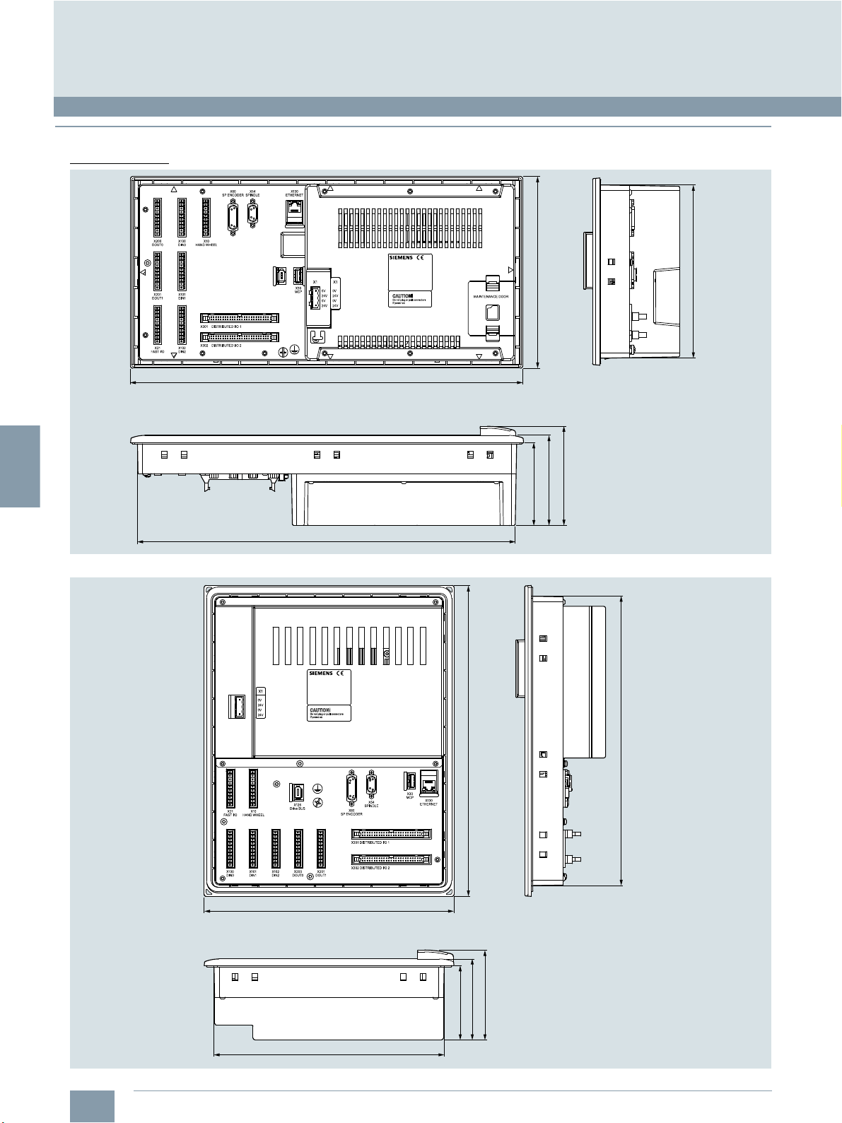
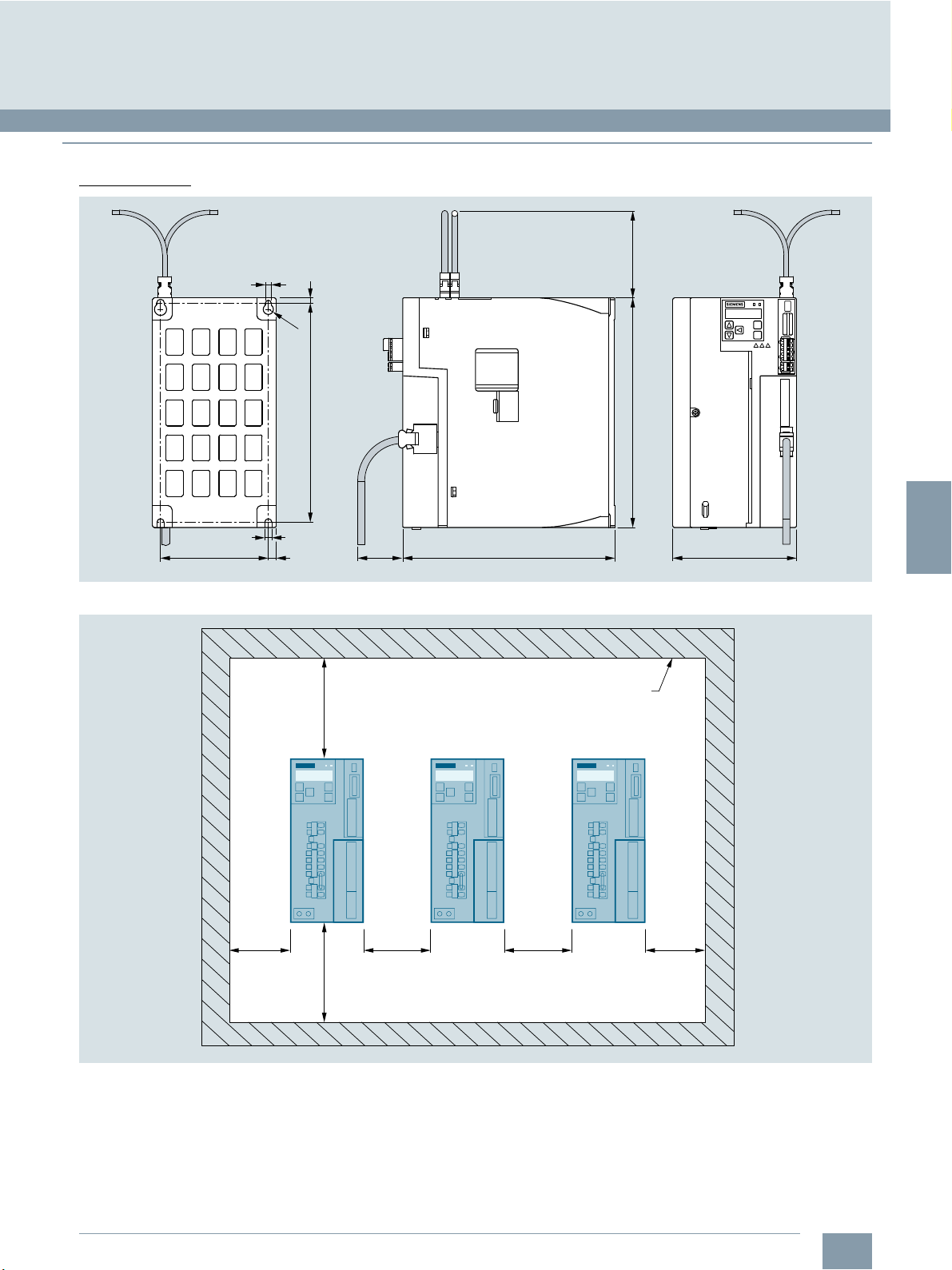
SINUMERIK 808D ADVANCED system
G_NC01_XX_00741
87
95
104
200
185
420
405
CNC control
SINUMERIK 808D ADVANCED PPU 15x.3/PPU 16x.3
■
Dimensional drawings
Dimensions in mm
© Siemens Industry, Inc. 2018
SINUMERIK 808D ADVANCED T/M horizontal
265
330
307
G_NC01_XX_00742
SINUMERIK 808D ADVANCED T/M vertical
3/4
Siemens NC 81.1 · 2019
244
96
86
79
Page 29
3
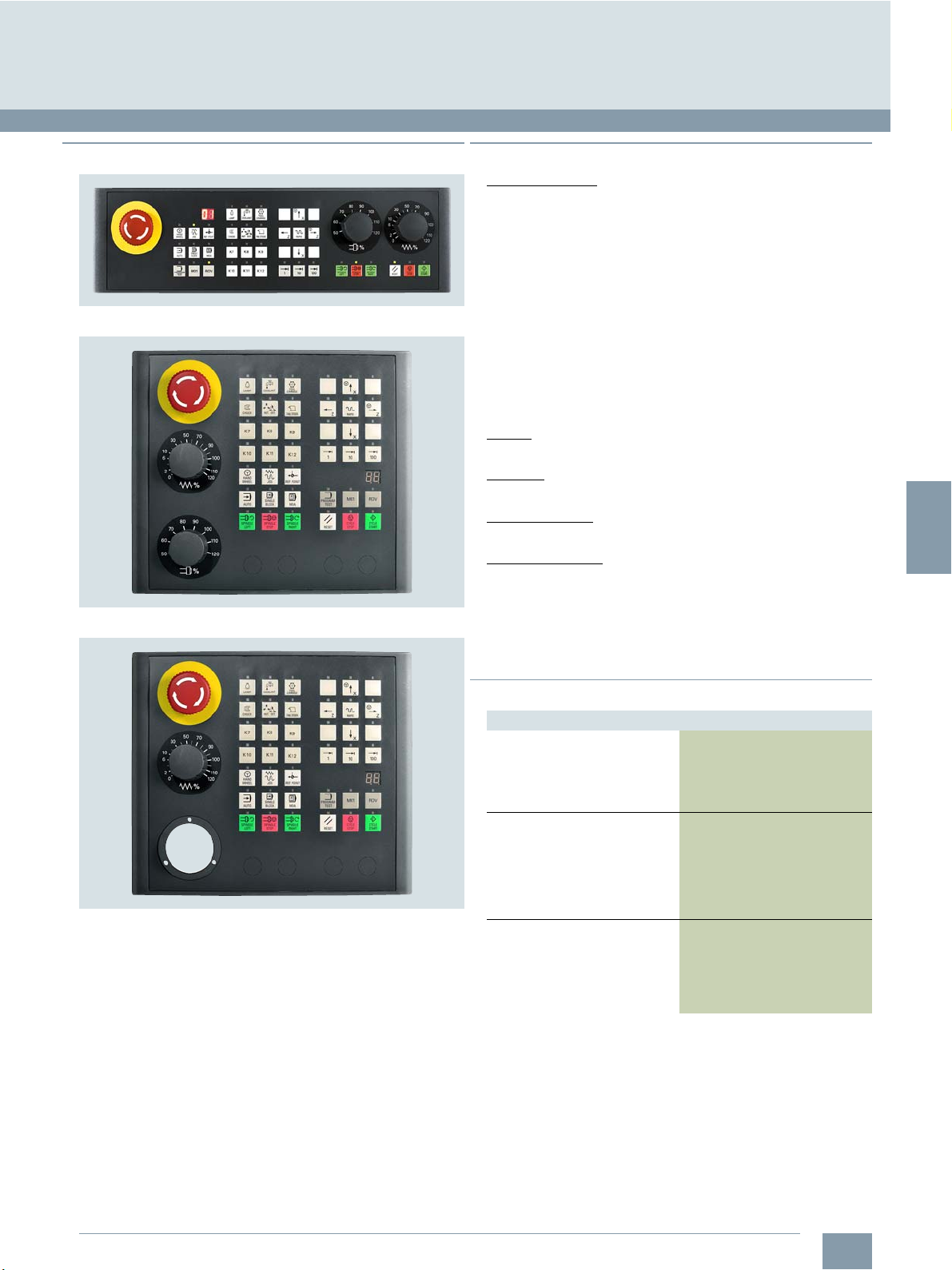
■
Overview
SINUMERIK 808D MCP horizontal
SINUMERIK 808D MCP vertical
© Siemens Industry, Inc. 2018
■
Design
Operator controls:
• Mode selectors and function keys
- 39 keys (horizontal version: of which 30 keys with LEDs,
vertical version: 39 keys with LEDs)
- Direction keys for machines with rapid traverse override
(The machine control panel is equipped with slide-in labels
for turning at the factory – slide-in labels for milling are
enclosed.)
- Preassigned keys for common functions, such as handwheel
selection, tool change, coolant control or program testing
• Horizontal version and vertical version without handwheel slot:
Spindle control with spindle override (rotary switch with
15 positions)
• Feedrate control with feedrate/rapid traverse override (rotary
switch with 18 positions)
• 7-segment display for tool number
Layout:
• English or Chinese Simplified
Key type:
• Mechanical keys with protection film
Interface to CNC:
•USB
Expansion options:
• 1 slot for emergency stop button (d = 22 mm)
• Horizontal version: 3 slots for control devices (d = 16 mm)
• Vertical version: 4 slots for control devices (d = 16 mm)
• 1 slot for handwheel (d = 44 mm), only for the vertical version
with handwheel slot. The handwheel with a diameter of 44 mm
must be ordered separately
SINUMERIK 808D ADVANCED system
Operator components
SINUMERIK 808D MCP horizontal/vertical
SINUMERIK 808D MCP vertical, with handwheel slot
The SINUMERIK 808D MCP machine control panels with
mechanical keys are designed to permit user-friendly, wellstructured operation of the machine functions. They are suitable
for machine-level operation of turning and milling machines.
Customized keys can be individually labeled using slide-in
strips.
The machine control panel is available as vertical and horizontal
version for different machine designs. Depending on the design
of the machine, the SINUMERIK 808D MCP can also be ordered
with a handwheel slot.
The machine control panel can be mounted from the rear using
special clamps without drilling holes into the cabinet.
■
Selection and ordering data
Description Article No.
SINUMERIK 808D MCP
machine control panel, horizontal
With USB cable
• English layout 6FC5303-0AF35-0AA0
• Simplified Chinese layout 6FC5303-0AF35-0CA0
SINUMERIK 808D MCP
machine control panel, vertical
with rotary switch for spindle
override
With USB cable
• English layout 6FC5303-0AF35-2AA0
• Simplified Chinese layout 6FC5303-0AF35-2CA0
SINUMERIK 808D MCP
machine control panel, vertical
with handwheel slot
With USB cable
• English layout 6FC5303-0AF35-3AA0
• Simplified Chinese layout 6FC5303-0AF35-3CA0
The following are included in the scope of delivery of the
SINUMERIK 808D MCP horizontal/vertical machine control
panel:
• USB cable 0.5 m
• Mounting clamps
• Slide-in labels for turning application (already inserted)
• Slide-in labels for milling applications
• Blank labeling strips for individual inscription
Siemens NC 81.1 · 2019
3/5
Page 30

3
© Siemens Industry, Inc. 2018
SINUMERIK 808D ADVANCED system
Operator components
SINUMERIK 808D MCP horizontal/vertical
■
Integration
The SINUMERIK 808D MCP machine control panel can be used for:
• SINUMERIK 808D ADVANCED T
• SINUMERIK 808D ADVANCED M
■
Technical specifications
Article No. 6FC5303-0AF35-0.A0 6FC5303-0AF35-..A0
Product name SINUMERIK 808D MCP
Supply voltage at DC 5 V via USB interface of PPU
Active power consumption maximum 5W
Degree of protection
•Front IP65
•Rear IP00
Environmental category acc. to IEC 60721-3-3 Condensation and icing excluded. Low air temperature 0 °C.
Relative humidity at 25 °C, during
•storage 5…95%
•transport 5…95%
•operation 5…90%
Ambient temperature, during
•storage -20 ... +60 °C
•transport -20 ... +60 °C
•operation
-front 0...45°C
-rear 0...50°C
Transmission link to PCU maximum 0.5 m
Width 420 mm 265 mm
Height 120 mm 230 mm
Depth 58 mm 58 mm
Mounting surface
• Section width 406 mm 245 mm
• Section height 106 mm 211 mm
• Tolerance + 1 mm + 1 mm
Net weight 0.86 kg
• With handwheel slot – 0.79 kg
• With rotary switch
Certificate of suitability
machine control panel
horizontal version
– 0.93 kg
CE, EAC
SINUMERIK 808D MCP
machine control panel
vertical version
3/6
Siemens NC 81.1 · 2019
Page 31

3
■
Dimensional drawings
Dimensions in mm
© Siemens Industry, Inc. 2018
SINUMERIK 808D ADVANCED system
Operator components
SINUMERIK 808D MCP horizontal/vertical
X10
NC
SINUMERIK 808D MCP horizontal
405
420
265
120
58
38
30
X10
NC
BB
230
210
105
G_NC01_XX_00552
G_NC01_XX_00551
244
SINUMERIK 808D MCP vertical with handwheel slot/without handwheel slot
30
38
58
Siemens NC 81.1 · 2019
3/7
Page 32
3
SINUMERIK 808D ADVANCED system
Feed axis solutions
SINAMICS V70 servo drive
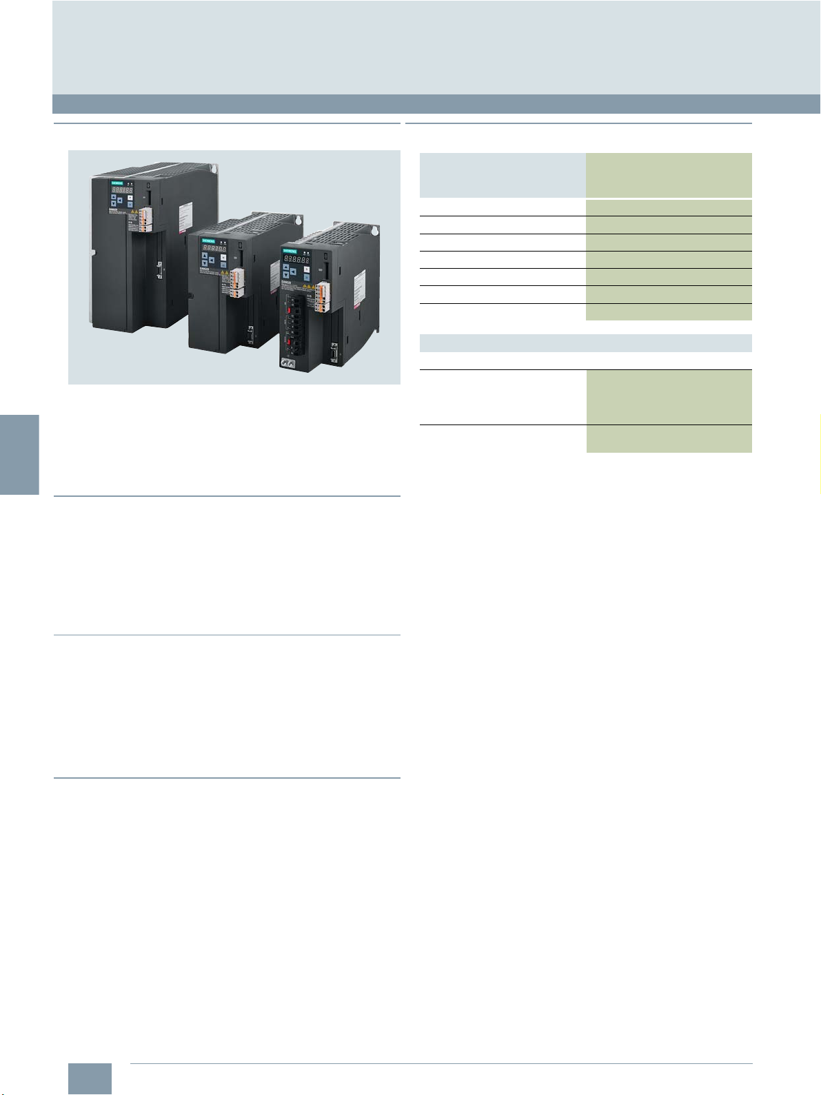
■
Overview
© Siemens Industry, Inc. 2018
■
Selection and ordering data
SINAMICS V70, frame sizes FSC/FSB/FSA
The SINAMICS V70 servo drive is specially designed to control
the feed axes in standard machine tool applications. The system
is designed essentially for applications where cost effectiveness
is the primary consideration. The key performance data of the
drive are aligned to perfectly fit to the solution provided by the
SINUMERIK 808D ADVANCED.
■
Benefits
7 Compact module with integrated infeed, inverter and closed-
loop position control for one feed axis
7 Coated electronic modules
7 Commissioning on CNC directly
7 Faster commissioning thanks to pre-configured motor data
stored in the drive.
7 CE certified
Rated output
current
A Article No.
1.2 FSA
3.0 FSA 6SL3210-5DE13-5UA0
4.6 FSB 6SL3210-5DE16-0UA0
5.3 FSB 6SL3210-5DE17-8UA0
7.8 FSB 6SL3210-5DE21-0UA0
11 FSC 6SL3210-5DE21-4UA0
13.2 FSC 6SL3210-5DE21-8UA0
Description Article No.
Spare parts
SINAMICS V70/V90
fan kits
• Frame size FSB 6SL3200-0WF00-0AA0
• Frame size FSC 6SL3200-0WF01-0AA0
SINAMICS V70
drive bus terminator
Frame size SINAMICS V70
servo drive
6SL3210-5DE12-4UA0
6FC5548-0BA21-0AA0
■
Function
• 7 versions cover power range from 0.4 kW to 7 kW
• Supply voltage 380 V to 480 V 3 AC
• 300 % overload capability
• Drive bus communication to the
SINUMERIK 808D ADVANCED
• Integrated motor brake switch
• Safe Torque Off (STO)
■
Integration
The following components can be connected to the
SINAMICS V70:
• SINUMERIK 808D ADVANCED PPU 15x.3/PPU 16x.3
• SIMOTICS S-1FL6 feed motor
• Encoder in SIMOTICS S-1FL6 feed motor
• Brake in SIMOTICS S-1FL6 feed motor
3/8
Siemens NC 81.1 · 2019
Page 33

3
■
1)
Minimum distance between drive modules: 10 mm.
Technical specifications
© Siemens Industry, Inc. 2018
SINUMERIK 808D ADVANCED system
Feed axis solutions
SINAMICS V70 servo drive
Article No.
Product name SINAMICS V70 servo drive
Frame size
Input voltage 380... 480V3AC -15%/+10%
Input frequency 50...60Hz ±10%
Infeed Non-stabilized
Electronics power supply 24 V DC ± 10 %
24 V DC supply 2.0 A (4.0 A) combined with motors without brake (with brake)
Cooling Natural cooling Forced ventilation
Ambient temperature
• Storage/transport -40 ... +70 °C
• Operation 0 ... 45 °C without derating,
Air humidity
• Storage/transport 90 % (non-condensing)
• Operation < 90 % (non-condensing)
Ambient conditions Indoor (without sunshine), without corrosive gas, combustible gas, oil gas, nor dust
Installation altitude Up to 1000 m without derating
Connectable motors SIMOTICS S-1FL6
Degree of protection IP20
Encoder evaluation Absolute encoder 20 bit/incremental encoder with 2500 S/R (13 bit resolution through electronic multiplication)
Output current
• Rated current I
• Peak current I
Rated output power P
Power loss 36 W 47 W 54 W 70 W 47 W 54 W 70 W
Cooling air required 0.005 m3/s 0.005 m3/s 0.005 m3/s 0.005 m3/s 0.005 m3/s 0.005 m3/s 0.005 m3/s
Conductor cross-section, max. 1.5 mm
Dimensions
• Width 80 mm 100 mm 140 mm
•Height 180 mm 180 mm 260 mm
•Depth 200 mm 200 mm 240 mm
Weight, approx. 1.85 kg 2.45 kg 5.65 kg
Certificate of suitability CE, EAC
S/R = Signals/Revolution
rated
max
rated
1)
6SL32105DE12-4UA0
FSA FSB FSC
> 45 ... 55 °C with derating (derating by 0 % at 45 °C up to 20 % at 55 °C)
1.2 A 3.0 A 4.6 A 5.3 A 7.8 A 11.0 A 13.2 A
3.6 A 9.0 A 13.8 A 15.9 A 23.4 A 33.0 A 39.6 A
0.4 kW 1kW 1.5 kW 1.75 kW 2.5 kW 3.5 kW 7kW
2
6SL32105DE13-5UA0
6SL32105DE16-0UA0
2
2.5 mm
6SL32105DE17-8UA0
6SL32105DE21-0UA0
6SL32105DE21-4UA0
6SL32105DE21-8UA0
Siemens NC 81.1 · 2019
3/9
Page 34
3
SINUMERIK 808D ADVANCED system
G_NC01_XX_00555
100
180
6
6
Ø11
168
6
9
63
50
200
80
Feed axis solutions
SINAMICS V70 servo drive
■
Dimensional drawings
Dimensions in mm
© Siemens Industry, Inc. 2018
SINAMICS V70, frame size FSA
SINAMICS V70, frame size FSB
82
100
Ø11
6
168
9
50
220
180
G_NC01_XX_00556
100
6
6
3/10
Siemens NC 81.1 · 2019
Page 35
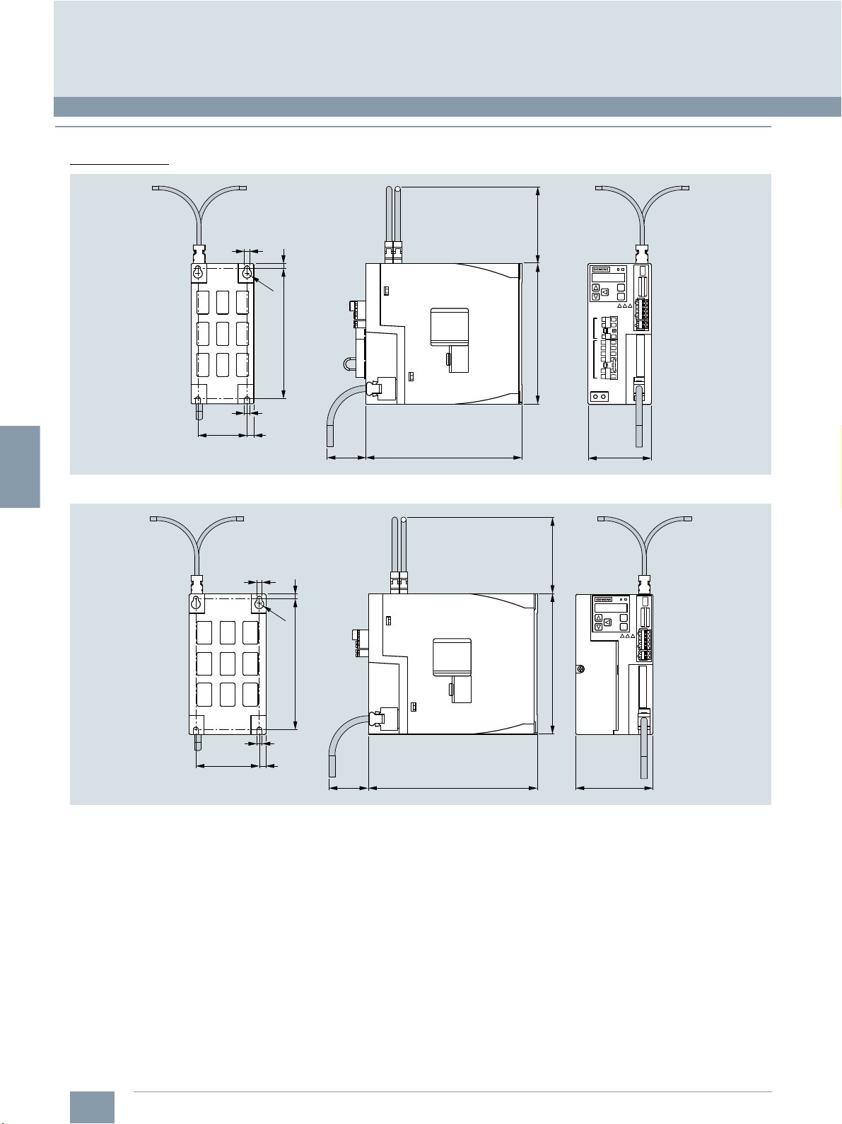
3
■
Dimensional drawings (continued)
Dimensions in mm
6
© Siemens Industry, Inc. 2018
SINUMERIK 808D ADVANCED system
Feed axis solutions
SINAMICS V70 servo drive
100
6
Ø11
122
SINAMICS V70, frame size FSC
248
6
9
> 100 mm
50
SINAMICS V70 Servo drive
240 140
260
G_NC01_XX_00557
Cabinet wall
Mounting clearance
> 10 mm > 10 mm> 10 mm> 10 mm
> 100 mm
G_NC01_EN_00558
Siemens NC 81.1 · 2019
3/11
Page 36
3
1)
It is not permissible to use the holding brake for an emergency stop.
2)
Shaft extension run-out, concentricity of centering ring and shaft, and
perpendicularity of flange to shaft.
© Siemens Industry, Inc. 2018
SINUMERIK 808D ADVANCED system
Feed axis solutions
SIMOTICS S-1FL6 feed motor
■
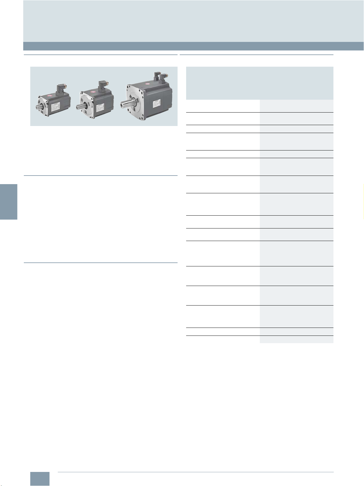
Overview
SIMOTICS S-1FL6 motors
SIMOTICS S-1FL6 motors are permanent-magnet synchronous
motors and designed for operation without external cooling.
The heat is dissipated through the motor surface. Quick and
easy mounting of the motors is possible. Together with the
SINAMICS V70, the SIMOTICS S-1FL6 feed motors provide a
highly dynamic solution for the machine tool application.
■
Benefits
7 High-performance magnet material
7 Rugged design with IP65 degree of protection for complete
motor including connectors
7 Smooth running quality thanks to low torque ripple
7 High rated speed for some variants
7 High acceleration due to the 300 % overload capacity
7 Rotatable connectors
7 Maximum flexibility due to variants with
incremental encoder/20 bit absolute encoder,
with/without brake and plain shaft/feather key,
half-key balancing
■
Function
• 3 motor shaft heights: SH 45, SH 65 and SH 90
• Rated speed of 2000 rpm/3000 rpm
• Max. speed up to 4000 rpm
• 300 % overload capacity
• Integrated 20 bit absolute encoder or incremental encoder
with 2500 S/R (13 bit resolution through electronic multiplication of the V70 drive)
• Degree of protection IP65, natural cooling
• Optional holding brake
• With plain shaft or feather key, half-key balancing
1)
■
Technical specifications
Article No. 1FL6...
Product brand name SIMOTICS
Product type designation S-1FL6
Product designation Feed motor
Type of motor Synchronous motor
Type of motor Permanent-magnet
Magnet material High-performance magnet
Cooling Natural cooling
Insulation of the stator winding in
accordance with EN 600034-1
(IEC 60034-1)
Thermal class B (130 °C)
Type of construction in
accordance with EN 60034-7
(IEC 60034-7)
Degree of protection in
accordance with EN 60034-5
(IEC 60034-5)
Shaft extension in accordance with
IEC 60072-1
Shaft and flange accuracy in
accordance with IEC 60072-12)
Vibration severity in accordance
with IEC 60034-14
Sound pressure level, max.
• 1FL604 65 dB
• 1FL606 70 dB
• 1FL609 70 dB
Ambient temperature
• Storage/transport -20 ... +65 °C
• Operation 0 ... 40 °C without derating
Humidity
• Storage/transport 90 % at 30 °C
• Operation 90 % at 30 °C
Installation altitude
Paint finish
Certificate of suitability CE, EAC
synchronous motor
material
Temperature class 130 (B)
IM B5 (IM V1, IM V3)
IP65, with oil seal
Plain shaft/feather key (C type,
motors with a keyway are
balanced with a half-fitted key
by the manufacturer)
Tolerance N
Grade A
Up to 1000 m above sea level
without power derating
>1000m...5000m
with power derating
Black
3/12
Siemens NC 81.1 · 2019
Page 37

3
1)
Rated power allows for a production tolerance of 10 %.
2)
Motor weight with incremental encoder.
3)
For SIMOTICS S-1FL6096-... motors with brake, when the ambient
temperature exceeds 30 ºC, the power should be derated by 10 %.
Power derating is not required for other motors.
© Siemens Industry, Inc. 2018
SINUMERIK 808D ADVANCED system
Feed axis solutions
SIMOTICS S-1FL6 feed motor
■
Selection and ordering data
Rated
Max.
speed
speed
n
ratednmax.
rpm rpm kW Nm Article No. 10
3000 4000 45 0.4 1.9 1FL6042-1AF61-2 ■ ■ 1 2.7 3.2 3.4 4.8 5DE12-4UA0 FSA
4000 0.75 3.5 1FL6044-1AF61-2 ■ ■ 1 5.2 5.7 5.2 6.6 5DE13-5UA0 FSA
2000 3000 65 0.75 4 1FL6061-1AC61-2 ■ ■ 1 8.0 9.1 5.7 8.8 5DE13-5UA0 FSA
3000 1 6 1FL6062-1AC61-2 ■ ■ 1 11.7 13.5 7 10.1 5DE13-5UA0 FSA
3000 1.5 8 1FL6064-1AC61-2 ■ ■ 1 15.3 16.4 8.4 11.5 5DE16-0UA0 FSB
3000 1.75 11 1FL6066-1AC61-2 ■ ■ 1 22.6 23.7 11.1 14.2 5DE17-8UA0 FSB
3000 2 15 1FL6067-1AC61-2 ■ ■ 1 29.9 31.0 13.7 16.8 5DE21-0UA0 FSB
2000 3000 90 2.5 15 1FL6090-1AC61-2 ■ ■ 1 47.4 56.3 15.4 21.5 5DE21-0UA0 FSB
3000 3.5 22 1FL6092-1AC61-2 ■ ■ 1 69.1 77.9 19.8 25.9 5DE21-4UA0 FSC
2500 5 30 1FL6094-1AC61-2 ■ ■ 1 90.8 99.7 24.4 30.5 5DE21-8UA0 FSC
2000 7
Encoder type
Incremental encoder 2500 S/R
Absolute encoder 20 bit
Shaft extension Holding brake
Feather key, half-key balancing
Feather key, half-key balancing
Plain shaft
Plain shaft
Shaft
height
SH P
Rated
1)
power
rated
at
T=100K
3)
Static
torque
M
0
at
T = 100 K
40 1FL6096-1AC61-2 ■ ■1 134.3 143.2 33.3 39.3 5DE21-8UA0 FSC
SIMOTICS S-1FL6
Feed motors
Synchronous motors
Natural cooling
Without
With
Without
With
Moment of
inertia of rotor
without
brake
J J m m
kgm
A
L
A
B
G
H
with
brake
-4
-4
10
2
kgm
2
2)
Weight
without
brake
kg kg Article No.
with
brake
SINAMICS V70
6SL3210-...
Frame
size
Siemens NC 81.1 · 2019
3/13
Page 38
3
SINUMERIK 808D ADVANCED system
Feed axis solutions
SIMOTICS S-1FL6 feed motor
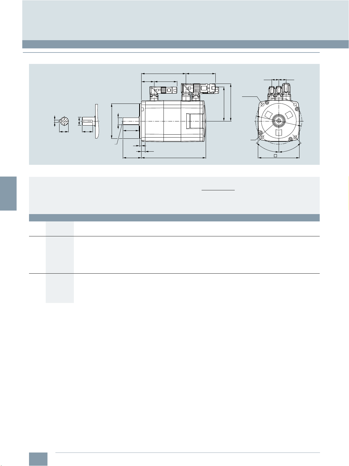
■
Dimensional drawings
© Siemens Industry, Inc. 2018
KB1
KB2
Version with feather key
F
DB
ØD
ØLB
E
T
LR
DE shaft extension Encoder system:
ØD
GA
SIMOTICS S-1FL6 feed motor with incremental encoder
For motor Dimensions in mm
Shaft
height
1FL6 natural cooling without/with brake
45 1FL6042 90 100 7 80 35 4 10 19 M6×16 30 25 21.5 6 154.5 93.5 – 201 140 31.5 96.2 84.6 13 14
65 1FL6061 130 145 9 110 58 6 12 22 M8×16 50 44 25 8 148 85.5 – 202.5 140 39.5 118 108 23 22
90 1FL6090 180 200 13.5 114.3 80 3 18 35 M12×25 75 60 38 10 189.5 140 – 255 206 44.5 143 133 34 34
Typ e without brake with brake
1FL6044 201.5 140.5 – 248 187
1FL6062 164.5 102 – 219 156.5
1FL6064 181 118.5 – 235.5 173
1FL6066 214 151.5 – 268.5 206
1FL6067 247 184.5 – 301.5 239
1FL6092 211.5 162 – 281 232
1FL6094 237.5 188 – 307 258
1FL6096 289.5 240 – 359 310
QK
LC LA LZ LB LR T LG D DB E QK GA F LL KB1 KB2 LL KB1 KB2 KL1 KL2 KL3 KL4
71
LG
LL
87.5
4 x ØLZ
KL1
KL2
Oil seal
Incremental encoder 2500 S/R
KL4 KL3
ØLA
45°
45°
LC
G_D011_EN_00526
3/14
Siemens NC 81.1 · 2019
Page 39
3
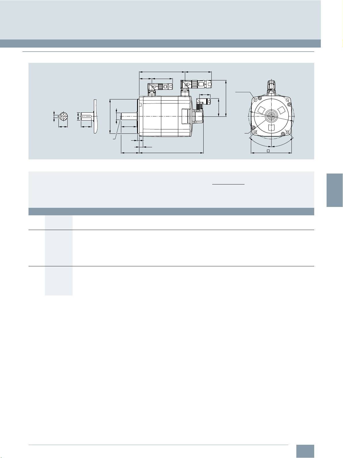
■
Dimensional drawings (continued)
© Siemens Industry, Inc. 2018
SINUMERIK 808D ADVANCED system
Feed axis solutions
SIMOTICS S-1FL6 feed motor
KB1
KB2
Version with feather key
F
DB
ØD
ØLB
E
T
LR
ØD
GA
SIMOTICS S-1FL6 feed motor with absolute encoder
For motor Dimensions in mm
Shaft
height
1FL6 natural cooling without/with brake
45 1FL6042 90 100 7 80 35 4 10 19 M6×16 30 25 21.5 6 157 100 – 203.5 147 31.5 96.2 60
65 1FL6061 130 145 9 110 58 6 12 22 M8×16 50 44 25 8 151 92 – 205.5 147 39.5 117.5 60
90 1FL6090 180 200 13.5 114.3 80 3 18 35 M12×25 75 60 38 10 197 135 – 263 201 44.5 143 60
Typ e without brake with brake
1FL6044 204 147 – 250.5 194
1FL6062 167.5 108.5 – 222 163.5
1FL6064 184 125 – 238.5 180
1FL6066 217 158 – 271.5 213
1FL6067 250 191 – 304.5 246
1FL6092 223 161 – 289 227
1FL6094 249 187 – 315 253
1FL6096 301 239 – 367 305
QK
LC LA LZ LB LR T LG D DB E QK GA F LL KB1 KB2 LL KB1 KB2 KL1 KL2
71
LG
LL
DE shaft extension Encoder system:
87.5
38
KL1
KL2
Oil seal
Absolute encoder 20 bit
4 x ØLZ
45°
LC
ØLA
45°
G_D011_EN_00527
Siemens NC 81.1 · 2019
3/15
Page 40
3
© Siemens Industry, Inc. 2018
SINUMERIK 808D ADVANCED system
Spindle solutions
SINAMICS V70 spindle drive
■
Overview
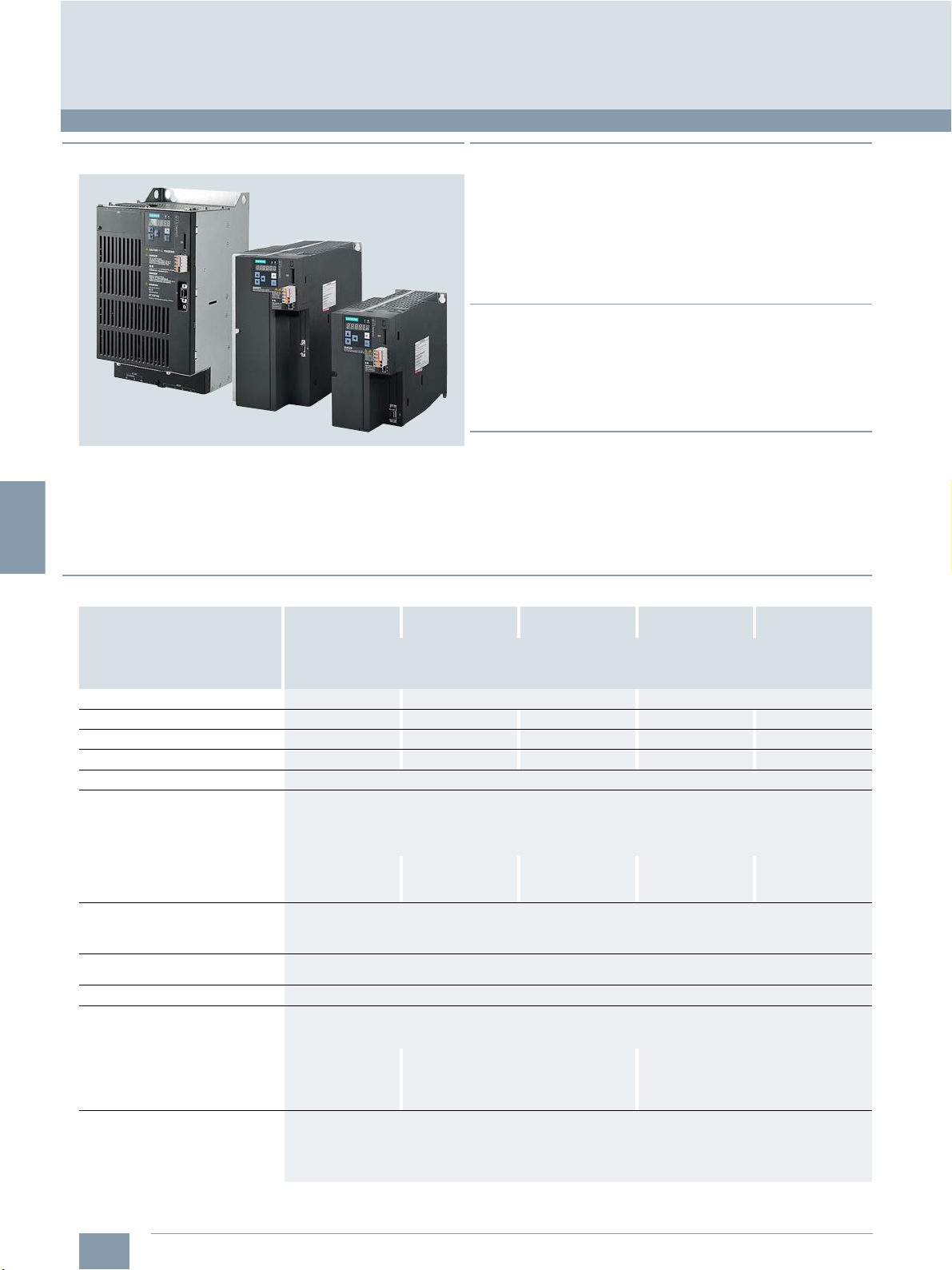
SINAMICS V70 spindle drive, frame sizes FSD/FSC/FSB
The SINAMICS V70 spindle drive controls the spindle in standard machine tool applications. The system is designed essentially for applications where cost effectiveness is the primary
consideration. The key performance data of the drive are
aligned to perfectly fit to the solution provided by the
SINUMERIK 808D ADVANCED.
■
Benefits
7 Compact module with integrated infeed, inverter and closed-
loop for spindle
7 Coated electronic modules
7 Commissioning on CNC directly
7 Faster commissioning thanks to pre-configured motor data
stored in the drive
7 CE certified
■
Function
• Power range from 3.7 kW to 15 kW
• Supply voltage 380 V to 480 V 3 AC
• Drive bus communication to the
SINUMERIK 808D ADVANCED
• Safe Torque Off (STO)
■
Integration
The following components can be connected to the
SINAMICS V70 spindle drive:
• SINUMERIK 808D ADVANCED PPU 15x.3/PPU 16x.3
• SIMOTICS M-1PH1 main spindle motor
• Encoder in SIMOTICS M-1PH1 main spindle motor
■
Technical specifications
Article No.
Product brand name
Product type designation
Product designation
Frame size
Rated output current
Max. output current
Max. supported motor power
Output frequency
Power supply
• Voltage/frequency 380 V... 480 V 3 AC, 50/60 Hz
• Permissible voltage fluctuation -15 % ... +10 %
• Permissible frequency fluctuation
• Rated input current
• Power supply capacity 8.7 kVA 10.7 kVA 16.1 kVA 24.5 kVA 30.9 kVA
• Inrush current 4A 2.5 A 2.5 A 2.5 A 2.5 A
24 V DC power supply
• Voltage 24 V (-15 % ... +20 %)
• Maximum current 3A
Overload capability
Control system
Braking resistor
• Resistance 70 27 18
•Max. power 9.1 kW 23.7 kW 37.4 kW
• Rated power 229 W 1185 W 1870 W
• Max. energy 18.3 kJ 189.6 kJ 299.2 kJ
Protective functions • Earthing fault protection
6SL32105DE21-1UA0
SINAMICS
V70
Spindle drive
FSB FSC FSD
10.5 A 12.9 A 19.6 A 29.8 A 37.6 A
21 A 24.6 A 39.2 A 59.6 A 75.2 A
3.7 kW 3.7 kW 7.5 kW 11 kW 15 kW
0 Hz to 400 Hz
-10 % ... +10 %
13.2 A 16.2 A 24.5 A 37.3 A 47 A
The overload capability is 150 % by default. It can be set up to 200 % via p0640, but the corresponding overload
duration might be reduced under the circumstances.
Servo control
Braking resistor is not included in the standard system package.
Choose an external braking resistor according to the technical specifications as listed below from Siemens product
portfolio or from 3rd party.
• Output short-cut protection
• Overvoltage/undervoltage protection
•I2t detection
• IGBT overtemperature protection
6SL32105DE21-3UA0
6SL32105DE22-0UA0
6SL32105DE23-0UA0
6SL32105DE24-0UA0
3/16
Siemens NC 81.1 · 2019
Page 41

3
© Siemens Industry, Inc. 2018
■
Technical specifications (continued)
Article No.
Product brand name
Product type designation
Product designation
Cooling method
Degree of protection
Degree of pollution
Operating environment
Relative humidity, during
•storage 90 % (non-condensing)
•operation < 90 % (non-condensing)
Ambient temperature, during
•storage -40°C...+70°C
•operation 0 °C ... 45 °C without power derating
Installation altitude
Vibration
• transport and storage 5 Hz ... 9 Hz: 3.5 mm deflection
•operation Operational area II/3M2
Shock
• transport and storage Covered by vibration test
•operation Operational area: II
Width
Height
Depth
Net weight
Certificate of suitability
6SL32105DE21-1UA0
SINAMICS
V70
Spindle drive
Fan-cooled
IP20
Class 2
Indoor (without direct sunlight), free from corrosive gas, combustible gas, oil gas, or dust
45 °C ... 55 °C with power derating
< 1000 m above sea level (without derating)
9Hz...200Hz: 1g vibration
Ambient Classification: 1M2
10 Hz ... 58 Hz: 0.075 mm deflection
58 Hz ... 200 Hz: 1 g vibration
Ambient classification: 3M2
Peak acceleration: 5 g + 15 g
Duration: 30 ms + 11 ms
Quantity of shocks: 3
Summed shocks: 18
Cycle time: 1 s
100 mm 140 mm 140 mm 190 mm 190 mm
180 mm 260 mm 260 mm 350 mm 350 mm
220 mm 240 mm 240 mm 185 mm 185 mm
2.35 kg 5.05 kg 5.05 kg 8.05 kg 8.3 kg
CE, EAC, RCM
6SL32105DE21-3UA0
SINUMERIK 808D ADVANCED system
Spindle solutions
SINAMICS V70 spindle drive
6SL32105DE22-0UA0
6SL32105DE23-0UA0
6SL32105DE24-0UA0
■
Selection and ordering data
Motor output
power
kW
Line voltage 380 V ... 480 V 3 AC
3.7 FSB 6SL3210-5DE21-1UA0
3.7 FSC 6SL3210-5DE21-3UA0
7.5 FSC 6SL3210-5DE22-0UA0
11 FSD 6SL3210-5DE23-0UA0
15 FSD 6SL3210-5DE24-0UA0
Frame size
SINAMICS V70
spindle drive
Article No.
■
Accessories
A shield plate can be ordered as an option for FSD devices.
Description Article No.
Shield plate
for V70 spindle drive
Frame size FSD 6SL3266-1ED00-0VA0
Siemens NC 81.1 · 2019
3/17
Page 42

3
SINUMERIK 808D ADVANCED system
G_NC01_XX_00557
100
260
6
6
Ø11
248
6
9
122
240 140
50
Spindle solutions
SINAMICS V70 spindle drive
■
Dimensional drawings
Dimensions in mm
6
6
Ø11
© Siemens Industry, Inc. 2018
100
6
82
SINAMICS V70 spindle drive, frame size FSB
168
9
50
220
180
G_NC01_XX_00556
100
SINAMICS V70 spindle drive, frame size FSC
Siemens NC 81.1 · 2019
3/18
Page 43

3
■
Dimensional drawings (continued)
Dimensions in mm
© Siemens Industry, Inc. 2018
SINUMERIK 808D ADVANCED system
Spindle solutions
SINAMICS V70 spindle drive
4-
140
Ø 6.5
25
6
337
SINAMICS V70 spindle drive, frame size FSD
19085 185
100
Ø 13
2-
G_NC01_EN_00724
140. 5
20
32612
304.5
20
Siemens NC 81.1 · 2019
3/19
Page 44

3
1)
This lifetime is only for reference. When a motor keeps running at rated
speed under rated load, replace its bearing after 20000 hours to
30000 hours of service time. Even if the time is not reached, the bearing
must be replaced when unusual noise, vibration, or faults are found.
© Siemens Industry, Inc. 2018
SINUMERIK 808D ADVANCED system
Spindle solutions
SIMOTICS M-1PH1 main spindle motor
■
Overview
SIMOTICS M-1PH1 main spindle motors SH 132/SH 100
1PH1 main spindle motors have been especially designed for
use as main drives in machine tools. These motors are available
as asynchronous version with forced fan cooling. Together with
the SINAMICS V70 spindle drive, a dynamic and powerful main
drive system with high performance is created.
■
Benefits
7 High productivity
- Short ramp up and ramp down time
- High overload capability
- Low moment of motor inertia
7 Better cutting performance
- High vibration resistance (R/S)
- Low torque ripple
7 Compact design
7 Easy commissioning together with drive
- Easy wiring via drive bus communication
- Easy parameter setting and monitor servo status in HMI
7 Easy service
- Fan design optimized for easy replacement
7 High robustness
- Optimized bearing concept for high transverse force
■
Technical specifications
Article No.
Product brand name
Product type designation
Product designation
Type of motor
Cooling
Ambient temperature, admissible
•Storage -20 ... +65 °C
• Operation -15 ... +40 °C
Relative humidity, during
•Storage 95 %
• Operation 90 %
Installation altitude
Maximum noise level
Thermal class
Vibration severity grade
• 1PH11..-1.F Grade B is maintained
• 1PH11..-1.D Grade B is maintained
Shock resistance
Static bearing lifetime
Oil seal lifetime
Encoder lifetime
Motor lifetime
Degree of protection
Type of construction
Paint finish
Certificate of suitability
1PH1...
SIMOTICS
M-1PH1
Main spindle motor
Squirrel-cage asynchronous motor
Forced ventilation
without power derating
Up to 1000 m above sea level
without power derating
72 dB
F
up to 1800 rpm
Grade S is maintained from
1800 rpm to 10000 rpm
up to 1800 rpm
Grade R is maintained from
1800 rpm to 6000 rpm
2.25 m/s2
(continuous in axial direction);
2
10 m/s
(continuous in radial direction)
> 20000 h
> 20000 h
> 20000 h
20000 h
IP54 (dust-tight and splash-proof
during motor operation)
IM B5, IM B3, IM V1, and IM V5
Anthracite
CE, EAC
1)
■
Function
• Robust, cost optimized design
• Shaft height: SH 100/SH 132
• Rated speed: 1000 rpm/1500 rpm
• Max. speed: up to 10000 rpm
• Rated output: 3.7 kW to 15 kW
• Rated torque 24 Nm to 105 Nm
• 2 times overload capability for high dynamic response
• Foot mounting and flange mounting available
• Degree of protection IP54
• Incremental encoder TTL 2500 S/R / Absolute encoder
single-turn 20-bit
• Plain shaft or with key
S/R = Signals/Revolution
3/20
Siemens NC 81.1 · 2019
Page 45

3
1)
Maximum speed that must not be exceeded.
© Siemens Industry, Inc. 2018
SINUMERIK 808D ADVANCED system
Spindle solutions
SIMOTICS M-1PH1 main spindle motor
■
Selection and ordering data
Rated
Maxi-
speed
mum
speed
n
ratednmax.
rpm rpm kW Nm Article No. A A Article No.
1000 6000 100 3.7 35 1PH1103-1 ■ D 1 ■ - ■ GA0 12.9 12.9 5DE21-3UA0 FSC
1500 10000 100 3.7 24 1PH1101-1 ■ F 1 ■ - ■ GA0 10.3 10.5 5DE21-1UA0 FSB
10000 5.5 35 1PH1103-1 ■ F 1 ■ - ■ GA0 16.9 19.6 5DE22-0UA0 FSC
10000 7.5 48 1PH1105-1 ■ F 1 ■ - ■ GA0 19.6 19.6 5DE22-0UA0 FSC
1000 6000 132 7.5 72 1PH1131-1 ■ D 1 ■ - ■ GA0 26.6 29.8 5DE23-0UA0 FSD
1500 8000 132 11 70 1PH1131-1 ■ F 1 ■ - ■ GA0 28.8 29.8 5DE23-0UA0 FSD
Encoder type
Incremental encoder TTL 2500 S/R L
Absolute encoder, single-turn, 20 bit H
Type of construction
IM B3/IM V5, foot mounting
IM B5/IM V1, flange mounting
Shaft extension DE Balancing
Plain shaft - 0
Feather key
Feather key
S/R = Signals/Revolution
Shaft
Rated
height
SH P
power
S1 duty
rated
1)
6000 5.5 53 1PH1105-1 ■ D 1 ■ - ■ GA0 18.8 19.6 5DE22-0UA0 FSC
6000 11 105 1PH1133-1 ■ D 1 ■ - ■ GA0 28.3 29.8 5DE23-0UA0 FSD
8000 15 96 1PH1133-1 ■ F 1 ■ - ■ GA0 36.7 37.6 5DE24-0UA0 FSD
Rated
torque
S1 duty
M
rated
SIMOTICS M-1PH1
Main spindle motors
Asynchronous motors
Forced ventilation
NDE DE
0
2
Full-key
Half-key
Rated
current
for
S1 duty
I
rated
1
2
SINAMICS V70 spindle drive
Rated
output
current
for S1
duty
I
rated
6SL3210-...
Frame
size
Siemens NC 81.1 · 2019
3/21
Page 46

3
© Siemens Industry, Inc. 2018
SINUMERIK 808D ADVANCED system
Spindle solutions
SIMOTICS M-1PH1 main spindle motor
■
Dimensional drawings
Mounting position
The SIMOTICS M-1PH1 main spindle motor supports flange
mounting and foot mounting as shown below:
Mounting method Standard type of
construction
Foot mounting IM B3 IM V5
Flange mounting IM B5 IM V1
Rotated type of
construction
Minimum clearance between a fan and parts/components
mounted by the customer
The minimum clearance between a fan and parts/components
mounted by the customer or the air discharge opening, and the
minimum clearance S between the air intake/air discharge
opening and adjacent components must be maintained.
Shaft
height
SH 100 Non-drive end axial,
327.5
Fan mounting Minimum
can be rotated through 180°
clearance
between a fan
and parts/
components
30 mm 30 mm
Minimum
clearance S
0.05 A
Center hole
C-type, M12×30
Ø180h7
key, GB/T1096
For motor Dimensions in mm
Shaft
height
1PH1, type of construction IM B5/IM V1
100
0.025
==
10
Ø38h6
A
Typ e
1PH1101-1.F12-.GA0
1PH1103-1.F12-.GA0
1PH1103-1.D12-.GA0
1PH1105-1.F12-.GA0
1PH1105-1.D12-.GA0
B
0.05
60.39.5
80
5
A
L
419
449
449
499
499
45°
158.6
196
Ø215
G_NC01_EN_00727
4-Ø14
L
196
3/22
Siemens NC 81.1 · 2019
Page 47

3
■
Dimensional drawings (continued)
0.025 A
Center hole
C-type, M12×30
Ø38h6
key, GB/T1096
==
9.5 60.3
80 L 199
© Siemens Industry, Inc. 2018
327.5
SINUMERIK 808D ADVANCED system
Spindle solutions
SIMOTICS M-1PH1 main spindle motor
258.6
0
-0.2
G_NC01_EN_00725
9.8
100
A
4-Ø12
160
119.6
For motor Dimensions in mm
Shaft
height
1PH1, type of construction IM B3/IM V5
100
Typ e
1PH1101-1.F10-.GA0
1PH1103-1.F10-.GA0
1PH1103-1.D10-.GA0
1PH1105-1.F10-.GA0
1PH1105-1.D10-.GA0
L L1
419 183
449 213
449 213
499 263
499 263
0.2 Total flatness of the four feet: 0.2
G_NC01_EN_00726
L1
Siemens NC 81.1 · 2019
3/23
Page 48
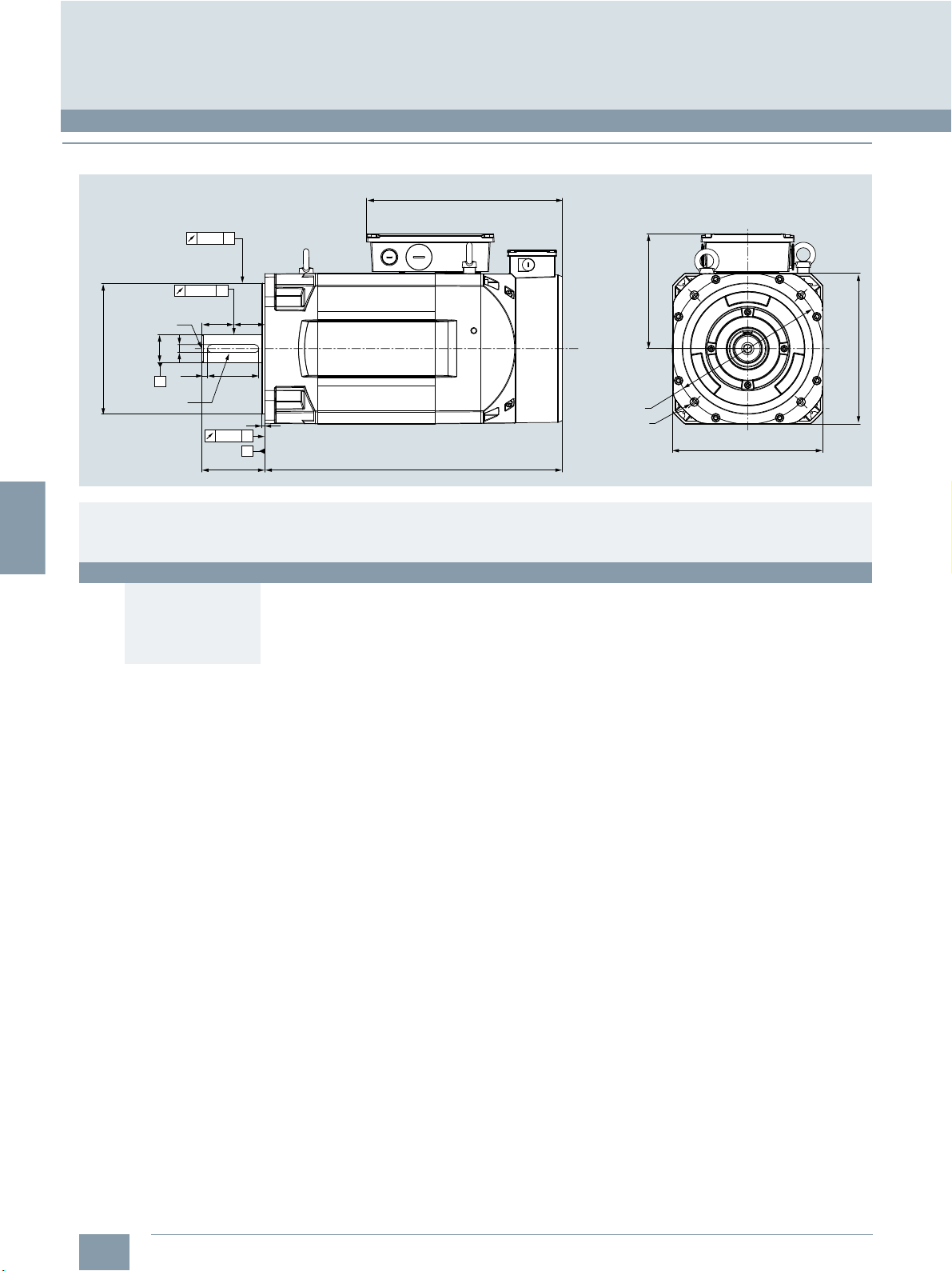
3
SINUMERIK 808D ADVANCED system
Spindle solutions
SIMOTICS M-1PH1 main spindle motor
■
Dimensional drawings (continued)
0.05
A
0.025
Center hole
C-type, M16×40
B
==
© Siemens Industry, Inc. 2018
341.4
14
Ø230h7
For motor Dimensions in mm
Shaft
height
1PH1, type of construction IM B5/IM V1
132 1PH1131-1.F12-.GA0 475
Ø48h6
9.5 90.3
A
key, GB/T1096
5
A
0.05
B
110
Typ e
1PH1131-1.D12-.GA0 465
1PH1133-1.F12-.GA0 525
1PH1133-1.D12-.GA0 525
L
264
Ø265
G_NC01_EN_00730
4-Ø15
264
L
3/24
Siemens NC 81.1 · 2019
Page 49
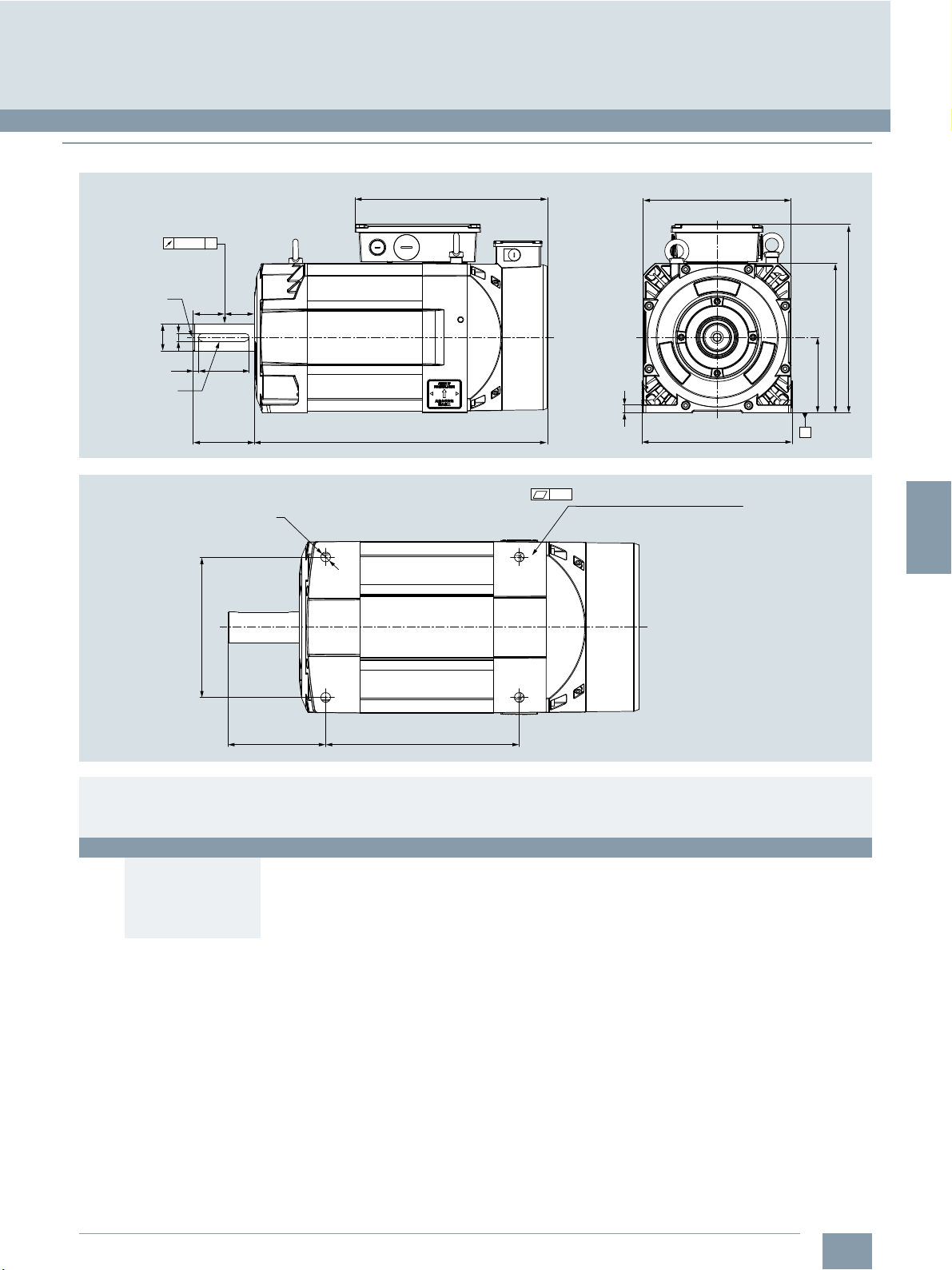
3
■
Dimensional drawings (continued)
© Siemens Industry, Inc. 2018
SINUMERIK 808D ADVANCED system
Spindle solutions
SIMOTICS M-1PH1 main spindle motor
Center hole
C-type, M16×40
Ø48h6
key, GB/T1096
0.025 A
==
14
9.5 90.3
110
216
4-Ø15
341.4
G_NC01_EN_00728
L
0.2
15
Total flatness of the four feet: 0.2
264
268.2
336.5
267
135
A
150.3
For motor Dimensions in mm
Shaft
height
1PH1, type of construction IM B3/IM V5
132
Typ e
1PH1131-1.F10-.GA0
1PH1131-1.D10-.GA0
1PH1133-1.F10-.GA0
1PH1133-1.D10-.GA0
L L1
475 251.8
465 241.8
525 301.8
525 301.8
G_NC01_EN_00729
L1
Siemens NC 81.1 · 2019
3/25
Page 50
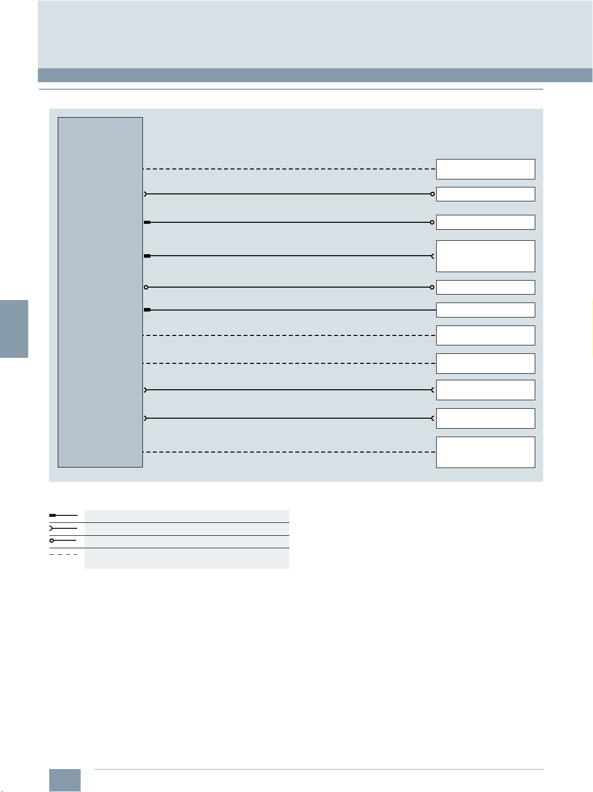
3
© Siemens Industry, Inc. 2018
SINUMERIK 808D ADVANCED system
MOTION-CONNECT connection systems
MOTION-CONNECT cables for SINUMERIK 808D ADVANCED
■
Integration
SINUMERIK 808D
ADVANCED T/M
X100/X101/X102
X200/X201
X1
X126
X54
X60
X10
X30
X301
Article No.
Pre-assembled cable
6FC5548-0BA20-….
0.25 m/0.35 m/1 m/3 m/5 m/7 m/10 m/15 m/20 m
(0.82 ft/1.1 ft/3.3 ft/9.8 ft/16 ft/23 ft/32 ft/49 ft/64 ft)
6FC5548-0BA05-….
3 m/5 m/7 m/10 m/15 m/20 m (9.8 ft/16 ft/23 ft/32 ft/49 ft/64 ft)
6FX8002-2CD01-....
5 m/7 m/10 m (16 ft/23 ft/32 ft)
6FX8002-2BB01-....
≤ 25 m (82 ft) for handwheel signals
USB cable
0.5 m (1.6 ft) (included in scope of delivery of MCP)
6EP5306-5BG00
≤ 6 m (20 ft)
Power supply
24 V DC
SINAMICS V70
Spindle drive
Incremental encoder for
spindle (TTL) RS422
6FX2001-2...
Handwheels (max. 2)
SINUMERIK 808D MCP
24 digital inputs
24 V DC
16 digital outputs
24 V DC
24 DI / 16 DO, 24 V DC
Terminal strip converter
X302
X21
Connection overview of SINUMERIK 808D ADVANCED T/M
Connector with pin contacts
Connector with socket contacts
Exposed core ends
Cable is not included in the scope of delivery.
It must be provided by the customer.
6EP5306-5BG00
≤ 6 m (20 ft)
Wire (0.14 ... 1.5 mm2)
24 DI / 16 DO, 24 V DC
Terminal strip converter
NC Ready, CW, CCW,
3 fast inputs (e.g. BERO
signals), 1 fast output 24 V DC
G_NC01_EN_00559e
3/26
Siemens NC 81.1 · 2019
Page 51

3
1)
The respective registration number is printed on the cable jacket.
© Siemens Industry, Inc. 2018
SINUMERIK 808D ADVANCED system
MOTION-CONNECT connection systems
MOTION-CONNECT cables for SINUMERIK 808D ADVANCED
■
Technical specifications
Article No. 6FC5548-0BA20-…. 6FC5548-0BA05-….
Product name Drive bus cable
No. of cores
Certificate of suitability
• cURus or UR/CSA
• RoHS conformity Yes Yes
Operating voltage 100 V 30 V
Test voltage, rms 3600 V 500 V
Operating temperature
on the surface
• Fixed installation -40 … +80 °C -20…+80°C
• Flexible installation -40 … +60 °C 0…60°C
Smallest bending radius
• Fixed installation 75 mm 60 mm
• Flexible installation
Insulation material,
incl. jacket
Oil resistance Limited mineral oil and fats resistance 70 °C × 4 h
Outer jacket PVC
Flame-retardant IEC 60332–3–24 VW-1
1)
PPU 15x.3/PPU 16x.3 – SINAMICS V70
SINAMICS V70 – SINAMICS V70
2 4
UL1581 UL2576
150 mm 120 mm
PVC PVC
Gray
Setpoint cable
PPU 15x.3/PPU 16x.3 – spindle drive
PVC
Gray
Article No. 6FX8002-2CD01-.... 6FX8002-2BB01-....
Product name Signal cable
Certificate of suitability
• cURus or UR/CSA
• RoHS conformity Ye s Ye s
Rated voltage 30 V 30 V
Test voltage, rms 500 V 500 V
Operating temperature
on the surface
• Fixed installation -50…+80°C -50…+80°C
• Flexible installation
Tensile stress, max.
• Fixed installation 50 N/mm
• Flexible installation 20 N/mm
Smallest bending radius
• Fixed installation 35 mm 35 mm
• Flexible installation 70 mm 70 mm
Torsional stress Absolute 30°/m Absolute 30°/m
Bending 10 million 10 million
Traversing velocity 300 m/min 300 m/min
Acceleration 5m/s
Insulation material,
incl. Jacket
Oil resistance EN 60811-2-1 EN 60811-2-1
Outer jacket PVC
Flame-retardant EN 60332-1-1 to 1-3 EN 60332-1-1 to 1-3
1)
PPU 15x.3/PPU 16x.3 –
Incremental encoder
for spindle (TTL)
UL758-CSA-C22.2-N.210.2-M90 UL758-CSA-C22.2-N.210.2-M90
-20…+60°C -20…+60°C
2
2
2
CFC/silicone-free
IEC 60754-1/DIN VDE 0472-815
DESINA color green RAL 6018
Signal cable
PPU 15x.3/PPU 16x.3 – handwheel
50 N/mm
20 N/mm
5m/s
CFC/silicone-free
IEC 60754-1/DIN VDE 0472-815
PVC
DESINA color green RAL 6018
2
2
2
For general information about MOTION-CONNECT please refer to Introduction.
Siemens NC 81.1 · 2019
3/27
Page 52

3
© Siemens Industry, Inc. 2018
SINUMERIK 808D ADVANCED system
MOTION-CONNECT connection systems
MOTION-CONNECT cables for SINUMERIK 808D ADVANCED
■
Selection and ordering data
Description Article No.
Pre-assembled bus cable
PPU PPU 15x.3/PPU 16x.3 –
SINAMICS V70 and
SINAMICS V70 – SINAMICS V70
Length
•0.25m 6FC5548-0BA20-1AA2
•0.35m 6FC5548-0BA20-1AA3
•1m 6FC5548-0BA20-1AB0
•3m 6FC5548-0BA20-1AD0
•5 m 6FC5548-0BA20-1AF0
•7 m 6FC5548-0BA20-1AH0
•10 m 6FC5548-0BA20-1BA0
•15m 6FC5548-0BA20-1BF0
•20 m 6FC5548-0BA20-1CA0
Pre-assembled setpoint cable
PPU PPU 15x.3/PPU 16x.3 –
spindle drive
Length
•3 m 6FC5548-0BA05-1AD0
•5 m 6FC5548-0BA05-1AF0
•7 m 6FC5548-0BA05-1AH0
•10 m 6FC5548-0BA05-1BA0
•15 m 6FC5548-0BA05-1BF0
•20 m 6FC5548-0BA05-1CA0
Pre-assembled signal cable
PPU PPU 15x.3/PPU 16x.3 –
incremental encoder
for spindle (TTL)
Length
•5 m 6FX8002-2CD01-1AF0
•7 m 6FX8002-2CD01-1AH0
•10 m 6FX8002-2CD01-1BA0
Pre-assembled signal cable
PPU PPU 15x.3/PPU 16x.3 –
handwheel
Length
•1 m 6FX8002-2BB01-1AB0
•5 m 6FX8002-2BB01-1AF0
•7 m 6FX8002-2BB01-1AH0
•10 m 6FX8002-2BB01-1BA0
3/28
Siemens NC 81.1 · 2019
Page 53
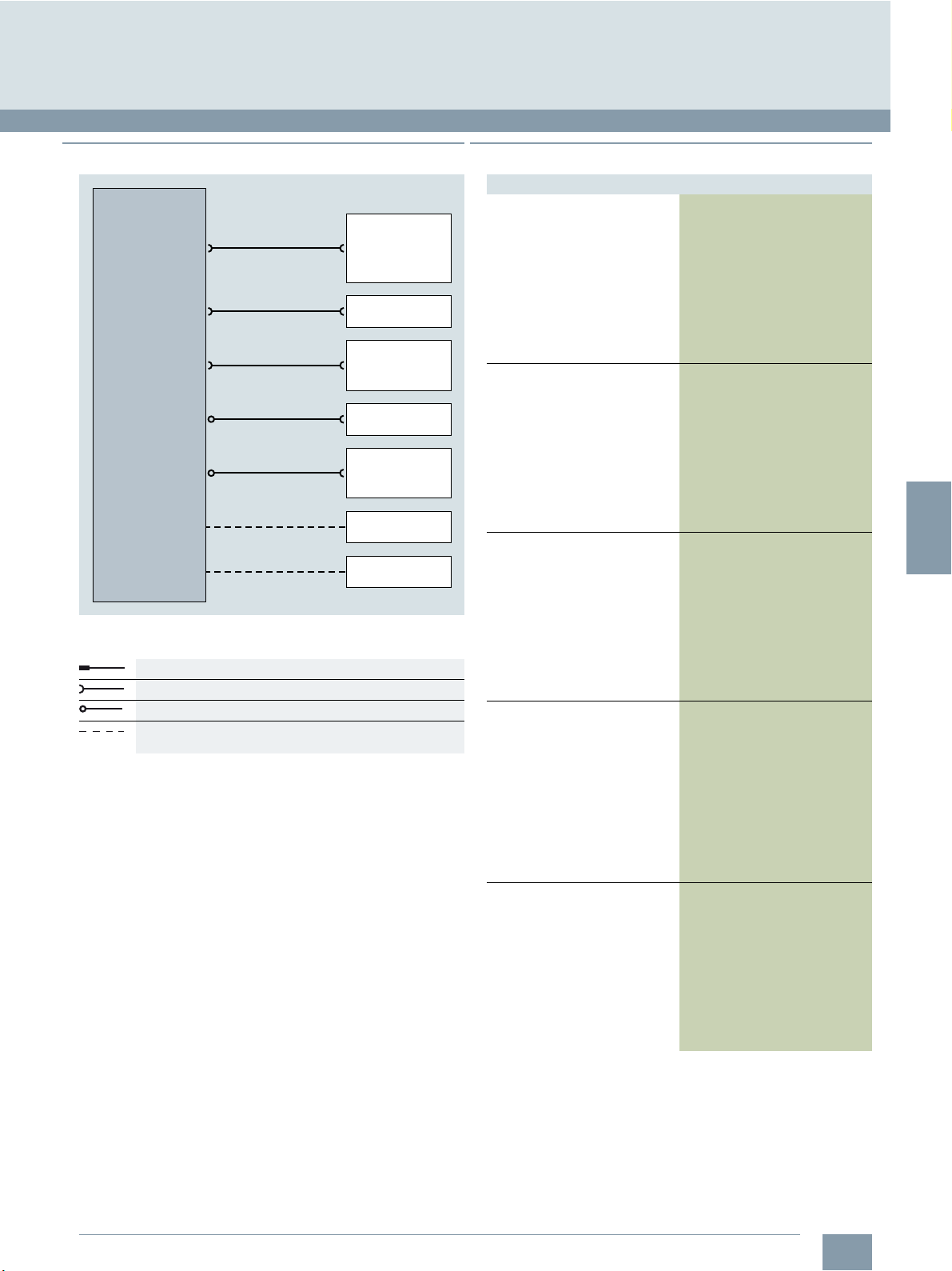
3
■
Integration
© Siemens Industry, Inc. 2018
MOTION-CONNECT cables for SINAMICS V70 servo drive
■
Selection and ordering data
SINUMERIK 808D ADVANCED system
MOTION-CONNECT connection systems
SINAMICS V70
servo drive
U / V / W
L1 / L2 / L3
Connection overview of SINAMICS V70 servo drive
Connector with pin contacts
Connector with socket contacts
Exposed core ends
Cable is not included in the scope of delivery.
It must be provided by the customer.
Article No.
Pre-assembled cable
6FC5548-0BA20-….
X10
3/5/7/10/15/20 m
(9.8/16/23/32/49/64 ft)
6FC5548-0BA20-....
X11
0.25/0.35/1 m
(0.82/1.1/3 ft)
6FX3002-2CT12-….
X9
3/5/7/10/15/20 m
(9.8/16/32/49/64 ft)
6FX3002-5CL02-….
3/5/7/10/15/20 m
(9.8/16/32/49/64 ft)
6FX3002-5BL03-….
X7
3/5/7/10/15/20 m
(9.8/16/32/49/64 ft)
X6
SINUMERIK 808D
ADVANCED
PPU 15x.3/
PPU 16x.3 (setpoint)
SINAMICS V70
X10
TTL encoder in
SIMOTICS S-1FL6
feed motor
SIMOTICS S-1FL6
feed motor
Brake in
SIMOTICS S-1FL6
feed motor
24 V DC
power supply
380 V 3 AC
main supply
G_NC01_EN_00753
Description Article No.
Pre-assembled signal cable
SINAMICS V70 –
SIMOTICS S-1FL6 feed motor
with absolute encoder
Length
•3m 6FX3002-2DB10-1AD0
•5m 6FX3002-2DB10-1AF0
•7m 6FX3002-2DB10-1AH0
•10m 6FX3002-2DB10-1BA0
•15m 6FX3002-2DB10-1BF0
•20m 6FX3002-2DB10-1CA0
Pre-assembled signal cable
SINAMICS V70 –
SIMOTICS S-1FL6 feed motor
with incremental encoder
Length
•3m 6FX3002-2CT12-1AD0
•5m 6FX3002-2CT12-1AF0
•7m 6FX3002-2CT12-1AH0
•10m 6FX3002-2CT12-1BA0
•15m 6FX3002-2CT12-1BF0
•20m 6FX3002-2CT12-1CA0
Pre-assembled power cable
4×1.5mm
SINAMICS V70, frame size FSA –
SIMOTICS S-1FL6 feed motor
Length
•3m 6FX3002-5CL02-1AD0
•5m 6FX3002-5CL02-1AF0
•7m 6FX3002-5CL02-1AH0
•10m 6FX3002-5CL02-1BA0
•15m 6FX3002-5CL02-1BF0
•20m 6FX3002-5CL02-1CA0
Pre-assembled power cable
4×2.5mm
SINAMICS V70,
frame size FSB/FSC –
SIMOTICS S-1FL6 feed motor
Length
•3m 6FX3002-5CL12-1AD0
•5m 6FX3002-5CL12-1AF0
•7m
•10m 6FX3002-5CL12-1BA0
•15m 6FX3002-5CL12-1BF0
•20m
Pre-assembled brake cable
SINAMICS V70 –
SIMOTICS S-1FL6 feed motor
with brake
Length
•3m 6FX3002-5BL03-1AD0
•5m 6FX3002-5BL03-1AF0
•7m 6FX3002-5BL03-1AH0
•10m 6FX3002-5BL03-1BA0
•15m 6FX3002-5BL03-1BF0
•20m 6FX3002-5BL03-1CA0
2
2
6FX3002-5CL12-1AH0
6FX3002-5CL12-1CA0
Siemens NC 81.1 · 2019
3/29
Page 54

3
© Siemens Industry, Inc. 2018
SINUMERIK 808D ADVANCED system
MOTION-CONNECT connection systems
MOTION-CONNECT cables for SINAMICS V70 servo drive
■
Technical specifications
Article No. 6FX3002-2DB10-....
Product name Signal cable
No. of cores 10 4 2
Degree of protection
(when closed and connected)
Certificate of suitability
•RoHS Yes Yes Ye s
•CE No Yes No
Rated voltage U0/U 30 V/30 V 600V/1000V 30 V/30 V
Test voltage, rms
Operating temperature
on the surface
• Fixed installation -15 … +80 °C -15…+80°C -15…+80°C
Tensile stress, max.
• Fixed installation 50 N/mm
• Flexible installation 20 N/mm
Smallest bending radius
• Fixed installation 6 × diameter 6 × diameter 6 × diameter
• Flexible installation 155 mm 155 mm 155 mm
Torsional stress Absolute 30°/m Absolute 30°/m Absolute 30°/m
Bending 1000000 1000000 1000000
Insulation material,
incl. jacket
Oil resistance EN 60811-2-1 EN 60811-2-1 EN 60811-2-1
Outer jacket PVC PVC PVC
Flame-retardant FT1 FT1 FT1
6FX3002-2CT12-….
SINAMICS V70 –
Encoder in SIMOTICS S-1FL6
feed motor
IP65 IP65 IP65
500 V 4kV 500 V
2
2
PVC PVC PVC
6FX3002-5CL02-....
6FX3002-5CL12-….
Power cable
SINAMICS V70 –
SIMOTICS S-1FL6 feed motor
50 N/mm
20 N/mm
2
2
6FX3002-5BL03-....
Signal cable
SINAMICS V70 –
brake in SIMOTICS S-1FL6
feed motor
50 N/mm
20 N/mm
2
2
For general information about MOTION-CONNECT please refer to Introduction.
3/30
Siemens NC 81.1 · 2019
Page 55
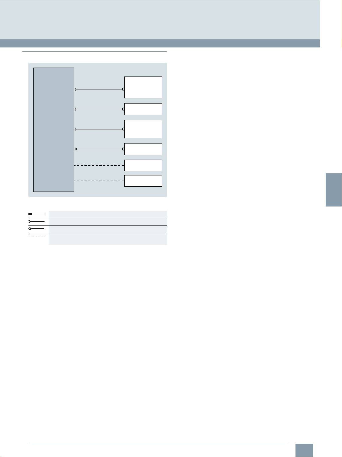
3
■
30 m (98 ft)
3/5/7/10/15/20 m
(9.8/16/32/49/64 ft)
3/5/7/10/15/20 m
(9.8/16/23/32/49/64 ft)
Pre-assembled cables
Article No.
6FX5008-1BB21-1DA0
6FX3002-2CT30-….
6FC5548-0BA20-….
TTL encoder in
SIMOTICS
M-1PH1 motor
SIMOTICS
M-1PH1 motor
24 V DC
power supply
380 V 3 AC
main supply
SINUMERIK 808D
ADVANCED
PPU 15x.3/
PPU 16x.3 (setpoint)
0.25/0.35/1 m
(0.82/1.1/3 ft)
6FC5548-0BA20-....
SINAMICS V70
X10
SINAMICS V70
spindle drive
G_NC01_EN_01048
X9
U / V / W
X6
L1 / L2 / L3
X10
X11
Integration
© Siemens Industry, Inc. 2018
SINUMERIK 808D ADVANCED system
MOTION-CONNECT connection systems
MOTION-CONNECT cables for SINAMICS V70 spindle drive
Connection overview for SINAMICS V70 spindle drive
Connector with pin contacts
Connector with socket contacts
Exposed core ends
Cable is not included in the scope of delivery.
It must be provided by the customer.
Siemens NC 81.1 · 2019
3/31
Page 56

3
© Siemens Industry, Inc. 2018
SINUMERIK 808D ADVANCED system
MOTION-CONNECT connection systems
MOTION-CONNECT cables for SINAMICS V70 spindle drive
■
Technical specifications
Article No. 6FX5008-1BB21-1DA0
Product name MOTION-CONNECT 500
No. of cores 4 10
Degree of protection
(motor side only)
Certificate of suitability
•RoHS Yes Yes
•CE Yes No
Rated voltage 1000 V 30 V
Operating temperature
on the surface
Smallest bending radius
• Fixed installation 5 × outer diameter 5 × outer diameter
• Flexible installation 180 mm, 210 mm 20 × outer diameter
Bending 100000 100000
Shielding Yes (coverage 80 %) Ye s
Oil resistance DIN VDE 472-803 Part B EN 60811-2-1
Outer jacket PVC PVC
Flame-retardant IEC 332.1 EN 60332-1-1 to 1-3
6FX5008-1BB31-1DA0
6FX5008-1BB51-1DA0
6FX5008-1BB61-1DA0
power cable
– IP20
-20…+80°C -30…+90°C
6FX3002-2CT30-....
6FX3002-2DB30-....
MOTION-CONNECT 300
signal cable
For general information about MOTION-CONNECT please refer to Introduction.
■
Selection and ordering data
Description Article No.
MOTION-CONNECT 500
power cable
4×2.5mm2, sold by the meter,
for SIMOTICS M-1PH1 motor
3.7 kW
Length
•30 m 6FX5008-1BB21-1DA0
MOTION-CONNECT 500
power cable
4×4 mm2, sold by the meter,
for SIMOTICS M-1PH1 motor
5.5 kW to 7.5 kW
Length
•30 m 6FX5008-1BB31-1DA0
MOTION-CONNECT 500
power cable
4×10 mm2, sold by the meter,
for SIMOTICS M-1PH1131-1.F...
motor
Length
•30 m 6FX5008-1BB51-1DA0
Description Article No.
MOTION-CONNECT 500
power cable
4×16 mm2, sold by the meter,
for SIMOTICS M-1PH1133-1.D...
motor and for
SIMOTICS M-1PH1133-1.F...
motor
Length
• 30 m 6FX5008-1BB61-1DA0
MOTION-CONNECT 300
pre-assembled signal cable
SINAMICS V70 spindle drive –
SIMOTICS M-1PH1 motor
with incremental encoder
Length
•3m 6FX3002-2CT30-1AD0
•5 m 6FX3002-2CT30-1AF0
•7 m 6FX3002-2CT30-1AH0
• 10 m 6FX3002-2CT30-1BA0
•15m 6FX3002-2CT30-1BF0
• 20 m 6FX3002-2CT30-1CA0
MOTION-CONNECT 300
pre-assembled signal cable
SINAMICS V70 spindle drive –
SIMOTICS M-1PH1 motor
with absolute encoder
Length
•3m 6FX3002-2DB30-1AD0
•5 m
•7 m 6FX3002-2DB30-1AH0
• 10 m 6FX3002-2DB30-1BA0
•15m 6FX3002-2DB30-1BF0
• 20 m 6FX3002-2DB30-1CA0
6FX3002-2DB30-1AF0
3/32
Siemens NC 81.1 · 2019
Page 57

3
1)
For braking resistor selection, please refer to page 3/16.
2)
The 30 m power cables (raw cables) listed above could be selected
for use with 1PH1 motors. You must assemble the power cable with
connectors by yourself. You could also select the third party power cable
by yourselves according to the system configuration.
© Siemens Industry, Inc. 2018
SINUMERIK 808D ADVANCED system
Sample packages
Sample package for Turning with SINUMERIK 808D ADVANCED T
■
Overview
The following composition of an equipment package is an
example of an inclined-bed lathe with:
• 2 machining axes (X, Z)
• 1 digital spindle with direct spindle encoder
• 24 digital PLC input signals and 16 digital PLC output signals
Designation Quantity Article No.
SINUMERIK CNC
SINUMERIK 808D ADVANCED T PPU 160.3 vertical, English layout 1 6FC5370-2BT03-0AA0
SINUMERIK 808D MCP vertical, with handwheel slot, English layout 1 6FC5303-0AF35-3AA0
Stabilized power supply, SITOP PSU200M 24 V, 5 A 1 6EP1333-3BA10
RS422 (TTL) incremental encoder, 1024 S/R 1 6FX2001-2EB02
Spring disk coupling, shaft diameter 6 mm/6 mm 1 6FX2001-7KF10
Clamp strap for encoders with Synchro flange 3 6FX2001-7KP01
Pre-assembled bus cable PPU 160.3 – SINAMICS V70, length 5 m 1 6FC5548-0BA20-1AF0
Pre-assembled bus cable SINAMICS V70 – SINAMICS V70, length 0.25 m 2 6FC5548-0BA20-1AA2
Pre-assembled signal cable PPU 160.3 – handwheel, length 1 m 1 6FX8002-2BB01-1AB0
Pre-assembled signal cable PPU 160.3 – incremental spindle encoder (TTL), length 5 m 1 6FX8002-2CD01-1AF0
SINAMICS V70
SINAMICS V70, I
SINAMICS V70, I
SINAMICS V70 spindle1), I
Pre-assembled signal cable SINAMICS V70 – absolute encoder in SIMOTICS S-1FL6 feed motor,
length 5 m
Pre-assembled power cable 4 × 1.5 mm
SINAMICS V70 – SIMOTICS S-1FL6 feed motor, length 5 m
Pre-assembled power cable 4 × 2.5 mm
SINAMICS V70 – SIMOTICS S-1FL6 feed motor, length 5 m
Pre-assembled brake cable SINAMICS V70 – brake in SIMOTICS S-1FL6 feed motor
with holding brake, length 5 m
Pre-assembled signal cable SINAMICS V70 – incremental encoder in M-1PH1, length 5 m 1 6FX3002-2CT30-1AF0
Power cable 4 × 4 mm2, sold by the meter, (optional)2)
SINAMICS V70 – SIMOTICS M-1PH1 main spindle motor, length 30 m
SIMOTICS motors
SIMOTICS S-1FL6 feed motor, 4 Nm, 2000 rpm, absolute encoder, plain shaft,
without holding brake
SIMOTICS S-1FL6 feed motor, 11 Nm, 2000 rpm, absolute encoder, plain shaft, with holding brake
SIMOTICS M-1PH1 main spindle motor, 53 Nm, 1000 rpm, incremental encoder, plain shaft
3.0 A 1 6SL3210-5DE13-5UA0
rated
5.3 A 1 6SL3210-5DE17-8UA0
rated
19.6 A 1 6SL3210-5DE22-0UA0
rated
2 6FX3002-2DB10-1AF0
2
2
1 6FX3002-5CL02-1AF0
1 6FX3002-5CL12-1AF0
1 6FX3002-5BL03-1AF0
1 6FX5008-1BB31-1DA0
1 1FL6061-1AC61-2LG1
1 1FL6066-1AC61-2LH1
1 1PH1105-1LD10-0GA0
Siemens NC 81.1 · 2019
3/33
Page 58

3
1)
For braking resistor selection, please refer to page 3/16.
2)
The 30 m power cables (raw cables) listed above could be selected
for use with 1PH1 motors. You must assemble the power cable with
connectors by yourself. You could also select the third party power cable
by yourselves according to the system configuration.
© Siemens Industry, Inc. 2018
SINUMERIK 808D ADVANCED system
Sample packages
Sample package for Milling with SINUMERIK 808D ADVANCED M
■
Overview
The following composition of an equipment package is an
example of a vertical machining center with:
• 3 machining axes (X, Y, Z)
• 1 digital spindle without direct spindle encoder
• 35 digital PLC input signals and 22 digital PLC output signals
Designation Quantity Article No.
SINUMERIK CNC
SINUMERIK 808D ADVANCED M PPU 161.3 horizontal, English layout 1 6FC5370-2AM03-0AA0
SINUMERIK 808D MCP, English layout 1 6FC5303-0AF35-0AA0
Electronic handwheel with front panel 120 mm × 120 mm, with setting wheel 5 V DC, RS422 1 6FC9320-5DB01
Terminal strip converter 50-pole 1 6EP5406-5AA00
Cable set, 50-pole ribbon cable, with insulation displacement connectors, 50-pole 1 6EP5306-5BG00
Stabilized power supply, SITOP PSU200M 24 V, 5 A 1 6EP1333-3BA10
Pre-assembled bus cable PPU 161.3 – SINAMICS V70, length 5 m 1 6FC5548-0BA20-1AF0
Pre-assembled bus cable SINAMICS V70 – SINAMICS V70, length 0.25 m 2 6FC5548-0BA20-1AA2
Pre-assembled bus cable SINAMICS V70 – SINAMICS V70, length 1 m 1 6FC5548-0BA20-1AB0
Pre-assembled signal cable PPU 161.3 – handwheel, length 1 m 1 6FX8002-2BB01-1AB0
Pre-assembled signal cable PPU 161.3 – incremental spindle encoder (TTL), length 7 m 1 6FX8002-2CD01-1AH0
SINAMICS V70
SINAMICS V70, I
SINAMICS V70, I
SINAMICS V70 spindle1), I
Pre-assembled signal cable SINAMICS V70 – incremental encoder in
SIMOTICS S-1FL6 feed motor, length 10 m
Pre-assembled power cable 4 × 2.5 mm
SINAMICS V70 – SIMOTICS S-1FL6 feed motor, length 10 m
Pre-assembled brake cable SINAMICS V70 – brake in SIMOTICS S-1FL6 feed motor, length 10 m 1 6FX3002-5BL03-1BA0
Pre-assembled signal cable SINAMICS V70 – incremental encoder in M-1PH1, length 10 m 1 6FX3002-2CT30-1BA0
Power cable 4 × 4 mm2, sold by the meter, (optional)2)
SINAMICS V70 – SIMOTICS M-1PH1 main spindle motor, length 30 m
SIMOTICS motors
SIMOTICS S-1FL6 feed motor, 8 Nm, 2000 rpm, incremental encoder, plain shaft,
without holding brake
SIMOTICS S-1FL6 feed motor, 15 Nm, 2000 rpm, incremental encoder, plain shaft,
with holding brake
SIMOTICS M-1PH1 main spindle motor, 48 Nm, 1500 rpm, incremental encoder, plain shaft 1 1PH1105-1LF12-0GA0
4.6 A 2 6SL3210-5DE16-0UA0
rated
7.8 A 1 6SL3210-5DE21-0UA0
rated
19.6 A 1 6SL3210-5DE22-0UA0
rated
3 6FX3002-2CT12-1BA0
2
3 6FX3002-5CL12-1BA0
1 6FX5008-1BB31-1DA0
2 1FL6064-1AC61-2AG1
1 1FL6067-1AC61-2AH1
3/34
Siemens NC 81.1 · 2019
Page 59

4
Accessories
© Siemens Industry, Inc. 2018
4/2 Operator components
4/2 Electronic handwheel
4/5 Supplementary components
4/5 Terminal strip converter
4/6 SITOP power supply
4/8 Direct spindle encoder
Siemens NC 81.1 · 2019
Page 60

4
© Siemens Industry, Inc. 2018
Accessories
Operator components
Electronic handwheel
■
Overview
Electronic handwheel
This handwheel generates signals which correspond to the
movements of the handwheel as it is turned. The axis selected
via the control can be positioned. The handwheels are equipped
with a magnetic latching mechanism that supports traversing
with incremental accuracy. The front panel can be removed.
■
Selection and ordering data
Description Article No.
Electronic handwheel
5 V DC, RS422
• With front panel
120 mm × 120 mm,
with setting wheel
• With front panel
76.2 mm × 76.2 mm,
with setting wheel
• Without front panel,
with small setting wheel
• Without front panel,
without setting wheel,
for installation
Adapter set
For installation in front panel
with 3-hole fixing
6FC9320-5DB01
6FC9320-5DC01
6FC9320-5DM00
6FC9320-5DF01
6FC9320-5DN00
■
Technical specifications
Article No. 6FC9320-5DB01 6FC9320-5DC01/
Product name Electronic handwheel
Rated voltage 5VDC±5% 5VDC±5%
Rated current, max. 60 mA 60 mA
Interface RS422 (TTL) RS422 (TTL)
Phase angle of pulse sequence A to B 90° electrical 90° electrical
Pulses 2×100S/R 2×100S/R
Actuating force 8Ncm 4Ncm
Output frequency, max. 2kHz 2kHz
Distance to PPU, max.
Degree of protection according to EN 60529
(IEC 60529)
•Front IP65 IP65
•Rear IP50 IP50
Relative humidity
•Storage 10 ... 95 % at 25 °C 10 ... 95 % at 25 °C
•Transport 10 ... 95 % at 25 °C 10 ... 95 % at 25 °C
• Operation 5 ... 80 % at 25 °C 5 ... 80 % at 25 °C
Ambient temperature
•Storage -40 ... +85 °C -40 ... +85 °C
•Transport -40 ... +85 °C -40 ... +85 °C
• Operation 0 ... 70 °C 0 ... 70 °C
Weight, approx. 0.6 kg 0.4 kg
Approvals, according to cULus cULus
S/R = Signals/Revolution
25 m 25 m
6FC9320-5DF01/
6FC9320-5DM00
4/2
Siemens NC 81.1 · 2019
Page 61

4
■
View A
Switch panel cutout
for mounting version
Flat connector for
push-on contacts 6.3 mm
DIN 46342 part 1
G_NC01_EN_00478
29.1
38.439.5
9.6
Ø58.5
76.20
Ø4.2
13.6
6.8
Ø15.1
+ 0.1
0
+ 0.05
0
A
Ø50
Ø40
4
65
65
Dimensional drawings
Dimensions in mm
39.4
29.1 11.60
A
Ø50
G_NC01_EN_00481
9.6
Flat connector for
push-on contacts 6.3 mm
DIN 46342 part 1
© Siemens Industry, Inc. 2018
64.3
12
h9
Ø7.98
Ø25
M15x1
25
View A
Accessories
Operator components
Electronic handwheel
Switch panel cutout
for mounting version
+ 0.1
Ø15.1
0
6.8
13.6
+ 0.05
0
Electronic handwheel without front panel without setting wheel
Electronic handwheel with front panel 76.2 mm × 76.2 mm
Siemens NC 81.1 · 2019
4/3
Page 62

4
Accessories
Operator components
Electronic handwheel
■
Dimensional drawings (continued)
Dimensions in mm
© Siemens Industry, Inc. 2018
29.1
Ø5.2
38.439.4
4
View A
G_NC01_EN_00479
Ø90
Ø63
100
120
Electronic handwheel with front panel 120 mm × 120 mm
29.6
Ø40
Ø58.5
A
Ø50
9.6
Flat connector for
push-on contacts 6.3 mm
DIN 46342 part 1
A
100
Ø50
9.6
Flat connector for
push-on contacts 6.3 mm
DIN 46342 part 1
37.939.9
G_NC01_EN_00480
Recomm. distance of 0.40 mm
switch panel/rotary button
Switch panel thickness 2 to max. 6 mm
Seal disc
View A
Switch panel cutout
for mounting version
Ø15.1
6.8
Switch panel cutout
for mounting version
6.8
13.6
13.6
+ 0.05
Ø15.1
+ 0.05
0
+ 0.1
0
0
+ 0.1
0
Electronic handwheel without front panel with small setting wheel
4/4
Siemens NC 81.1 · 2019
Page 63

4
© Siemens Industry, Inc. 2018
■
Overview
Terminal strip converter
The SINUMERIK 808D ADVANCED PPU 15x.3/PPU 16x.3 feature
24 digital PLC inputs and 16 digital PLC outputs which can be
connected directly using screw-clamps on the PPU.
In addition, the PPU 15x.3/PPU 16x.3 feature 48 digital PLC
inputs and 32 digital PLC outputs which can be connected via
2 terminal strip converters.
This allows the connection of process signals directly in the
cabinet with significantly reduced wiring efforts.
Supplementary components
■
Design
Connection of PLC process signals
• Screw-clamps
- 24 digital inputs
- 16 digital outputs
Connection to PPU
• Ribbon cable, 50-pole
• Insulation displacement connectors
Cabinet mounting
• Standard mounting rails
■
Selection and ordering data
Description Article No.
Terminal strip converter
50-pin
Cable set
Ribbon cable, 50-pin
length: 6 m
8 insulation displacement
connectors, 50-pin
6EP5406-5AA00
6EP5306-5BG00
Accessories
Terminal strip converter
■
Dimensional drawings
Dimensions in mm
50
43.7
17.5
22.5
45
G_NC01_XX_00473
6.3
151
Terminal strip converter
Siemens NC 81.1 · 2019
4/5
Page 64
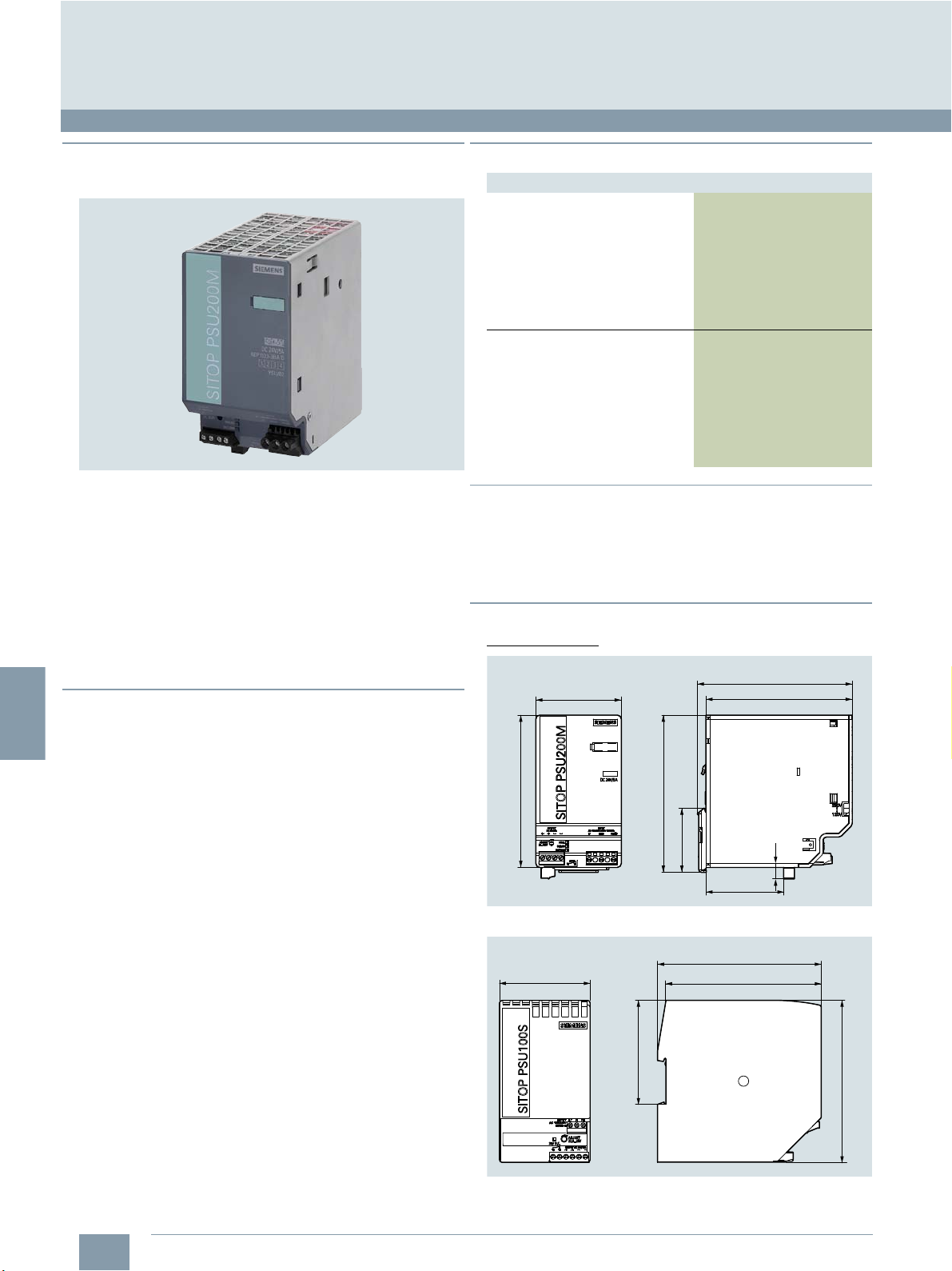
4
Accessories
Supplementary components
SITOP power supply
■
Overview
Stabilized power supply units
© Siemens Industry, Inc. 2018
■
Selection and ordering data
Description Article No.
Stabilized power supply
SITOP modular
SITOP PSU200M 24 V DC/5 A
Input voltage:
120 V/230 V AC
(85 … 264 V/176 ... 550 V AC)
Output voltage:
24 V DC ± 3 %
Approvals: cULus, CSA
Stabilized power supply
SITOP smart
PSU100S 24 V DC/10 A
Input voltage:
120 V/230 V AC
(85 … 132 V/170 ... 264 V AC)
Output voltage:
24 V DC ± 3 %
Approvals: cULus, CSA
6EP1333-3BA10
6EP1334-2BA20
SITOP modular power supply unit
The 24 V power supply units from the SITOP range are optimized
for industrial use and operate on the switched-mode principle.
Due to the precisely regulated output voltage, the devices are
even suitable for the connection of sensitive sensors.
SITOP smart/modular
Slimline dimensions, strong performance. SITOP smart/modular
requires little space on the mounting rail and offers high performance at a reasonable price. With its tolerant overload
response, even loads with a high inrush current can be smoothly
switched on.
If required, 50 % extra power is made available for 5 seconds.
■
Benefits
7 High efficiency
7 Low space requirements and easy installation
7 Exact output voltage and low residual ripple
7 Integrated short-circuit protection and safe electrical
separation
7 National and international approvals
7 No release of silicone
■
More information
You can find additional information in Catalog KT 10.1 or on the
Internet at:
www.siemens.com/sitop
www.siemens.com/industrymall
■
Dimensional drawings
Dimensions in mm
70
125
Stabilized power supply SITOP modular 5 A
129
52.3
127.2
120
9.5
64
4/6
Siemens NC 81.1 · 2019
70
79.8
Stabilized power supply SITOP smart 10 A
126.5
120
125
G_KT01_XX_00733
Page 65

4
© Siemens Industry, Inc. 2018
■
Application
RS422 (TTL) incremental encoder
The optoelectronic incremental TTL encoders are tailored for the
use as direct spindle encoders in conjunction with the
SINUMERIK 808D CNCs.
Accessories
Direct spindle encoder
Direct spindle encoder
■
Design
The direct incremental spindle encoder features a Synchro
flange and can be attached to the machine with 3 clamp straps
and a spring disk coupling.
The encoder supply voltage of 5 V DC is provided by the
SINUMERIK 808D CNC.
The direct incremental spindle encoder delivers specific pulses
per revolution according to your selection which are multiplied
by the factor of 4 internally to reach the precision level suitable
for standard lathes and milling machines.
Incremental encoders operate on the principle of optoelectronic
scanning of dividing disks with the transmitted light principle.
With an appropriate arrangement of the line pattern on the
dividing disk connected to the shaft and the fixed aperture, the
optoelectronic elements provide two trace signals A and B at
90° to one another, as well as a reference signal R. The encoder
electronics amplify these signals and convert them into different
output levels.
Siemens NC 81.1 · 2019
4/7
Page 66

4
1)
With recommended cable and input circuitry of the downstream
electronics, observe max. permissible cable length of module to be
evaluated.
© Siemens Industry, Inc. 2018
Accessories
Direct spindle encoder
Direct spindle encoder
■
Technical specifications
Article No. 6FX2001-2E...
Product name RS422 (TTL)
Operating voltage U
on encoder
Scanning frequency, max. 300 kHz
No-load current
consumption, max.
Resolution, max. 5000 S/R
Signal level RS422 (TTL)
Outputs protected against
short-circuit to 0 V
Switching time (10 ... 90 %)
(for 1 m cable and recommended
input circuit)
Phase angle, signal A to B
Edge spacing, min.
•At 300kHz 0.45 s
Cable length to downstream
electronics, max.
Accuracy
(in angular seconds)
LED failure monitoring High-resistance driver
Maximum mechanical speed 12000 rpm
Starting torque (at 20 °C) 0.01 Nm
Shaft loading capacity
•n 6000 rpm
- Axial 40 N
- Radial at shaft extension 60 N
•n>6000rpm
- Axial 10 N
- Radial at shaft extension 20 N
Shaft diameter 6mm
Shaft length 10 mm
Angular acceleration, max. 105rad/s
Moment of inertia of rotor 2.9×10⁻⁶kgm
Vibration (55 ... 2000 Hz) to
EN 60068-2-6
Shock to EN 60068-2-27
•2ms 2000 m/s
Degree of protection to
EN 60529 (IEC 60529)
• At housing IP67
• At shaft input IP64
Ambient temperature
Operation
• Flange outlet
-AtUp = 5V ±10% -40 ... +100 °C
Net weight 0.3 kg
EMC EMC Directive 2014/30/EC and
Certificate of suitability
S/R = Signals/Revolution
p
1)
incremental encoder for spindle
5VDC ±10%
150 mA
Yes
Rise/fall time
t
50 ns
+/t-
90°
100 m without fault signal
50 m with fault signal
± 18 mech. × 3600/
PPR count z
2
2
300 m/s
regulations of EMC directives
(applicable basic standards)
CE, CSA, UL
2
2
■
Technical specifications (continued)
Article No. 6FX2001-7KF10
Product name Spring disk
Transferable torque, max. 0.8 Nm
Shaft diameter 6 mm both ends
Center offset of shafts, max. 0.4 mm
Axial displacement ±0.4mm
Angular displacement
of shafts, max.
Torsional rigidity 150 Nm/rad
Lateral spring stiffness 6N/mm
Moment of inertia 19 gcm
Speed mechanical max. 12000 rpm
Ambient temperature
• Operation -40 ... +150 °C
Net weight 16 g
■
Selection and ordering data
Description Article No.
RS422 (TTL) incremental
encoder
Synchro flange
5 V DC supply voltage
Radial flange outlet
•500S/R 6FX2001-2EA50
• 1000 S/R 6FX2001-2EB00
• 1024 S/R 6FX2001-2EB02
• 1250 S/R 6FX2001-2EB25
• 1500 S/R 6FX2001-2EB50
• 2000 S/R 6FX2001-2EC00
• 2048 S/R 6FX2001-2EC04
• 2500 S/R 6FX2001-2EC50
• 3600 S/R 6FX2001-2ED60
• 5000 S/R 6FX2001-2EF00
Spring disk coupling
For shaft diameter 6 mm/6 mm
Clamp strap (1 unit)
For encoders with Synchro flange
(3 units are required)
S/R = Signals/Revolution
coupling
3°
6FX2001-7KF10
6FX2001-7KP01
2
4/8
Siemens NC 81.1 · 2019
Page 67
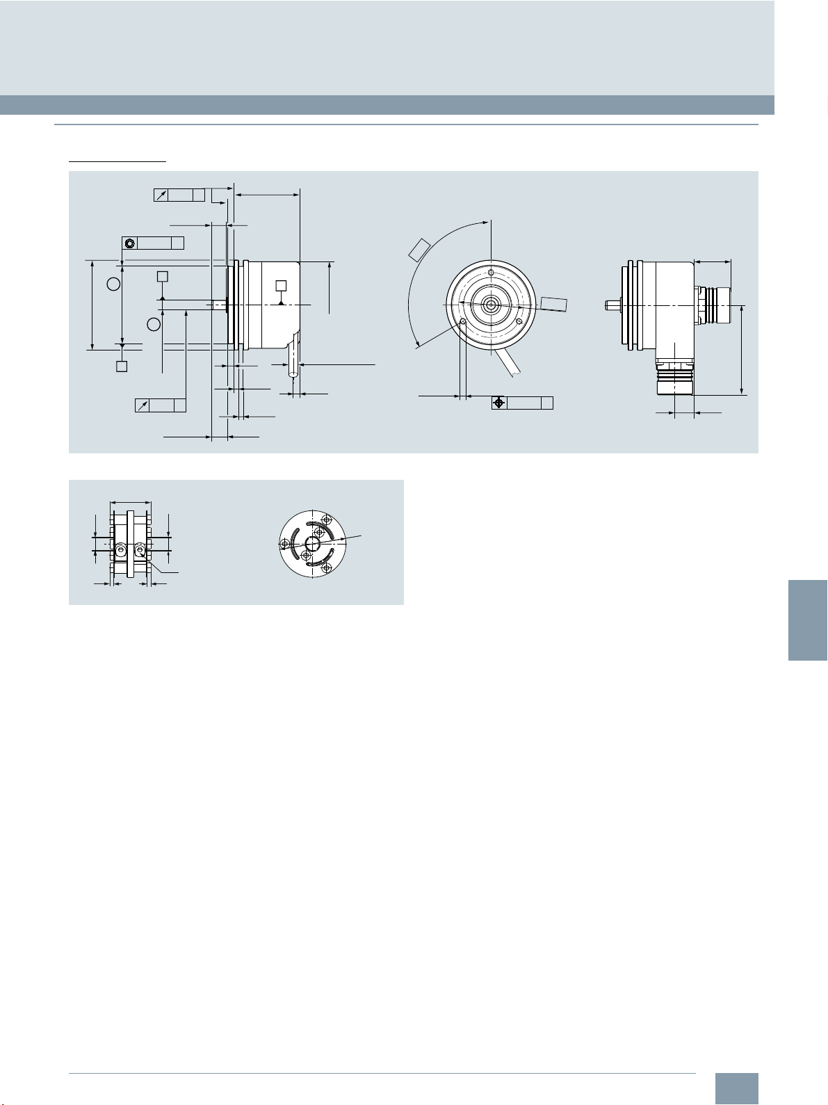
4
■
Dimensional drawings
Dimensions in mm
© Siemens Industry, Inc. 2018
Accessories
Direct spindle encoder
Direct spindle encoder
0.08
A
9.5±0.1
Ø 0.08
B
Ø 50h7
C
E
-0.01
-0.02
Ø 6
0.03
B
A
10.5±0.5
E
Ø 58
RS422 (TTL) incremental encoder
18.5
n d1H8
n d2 H8
M2.5 × 10 DIN 912
12.9 (2 ×)
1.5 1.5
42.7±0.5
4
0.1
3
-0.1
+0.2
3
0
A
Ø 56
Ø 6
EnDat22: Ø 4.5
4.4
Ø30
120°
3×
Ø 42
M4 × 5
G_NC01_EN_00474
3×
Ø 0.25
C
23.6
58.1
12.5
G_NC01_EN_00475
Spring disk coupling, d1=d2=6mm
Siemens NC 81.1 · 2019
4/9
Page 68

4
Accessories
Notes
© Siemens Industry, Inc. 2018
4/10
Siemens NC 81.1 · 2019
Page 69
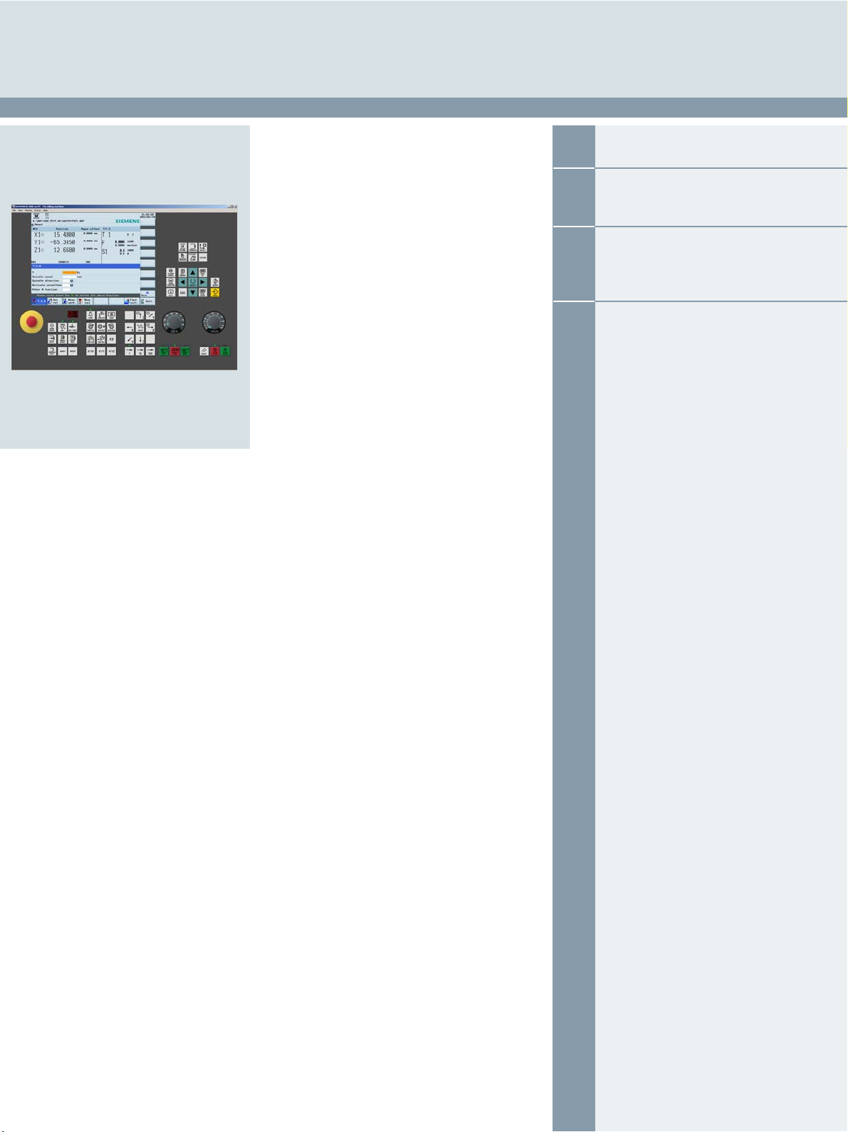
5
Services and training
© Siemens Industry, Inc. 2018
5/2 Services
5/2 Material warranty and on-site service
5/3 Training
5/3 Training services
5/4 SINUMERIK 808D on PC
5/5 Siemens Automation Cooperates
with Education (SCE)
5/5 Teaching made easy – Comprehensive
support on the way to Industrie 4.0
5/8 Documentation
5/8 Specific documentation for
SINUMERIK 808D ADVANCED
Siemens NC 81.1 · 2019
Page 70
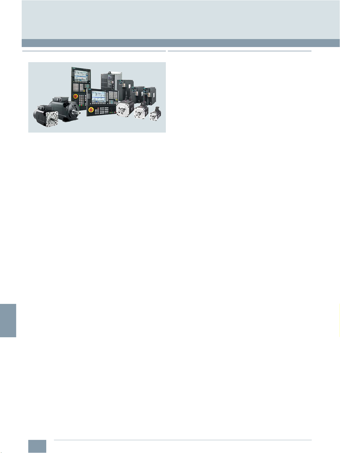
5
Services and training
1)
Not applicable to complete motor spindles.
2)
Standard warranty period: 24 months from 1st delivery of equipment
package from Siemens factory.
Extended warranty period: 36 months from 1st delivery of equipment
package from Siemens factory. When registration completed within
standard warranty period.
Services
Material warranty and on-site service
■
Overview
Equipment package SINUMERIK 808D ADVANCED T, PPU 161.3,
horizontal with MCP - SINAMICS V70 FSA ... FSD, 400 V 3 AC –
SIMOTICS S-1FL6 servomotors - SIMOTICS M-1PH1 main spindle
motor
For the SINUMERIK 808D ADVANCED and the associated
components
warranty and free on-site service of up to 36 months
1)
by Siemens DF & PD you will receive a material
© Siemens Industry, Inc. 2018
■
More information
For the material warranty and on-site support the same scope
as for Repair Service Contracts applies. Further information can
be found at:
www.siemens.com/automation/oss
2)
.
5/2
Siemens NC 81.1 · 2019
Page 71

5
© Siemens Industry, Inc. 2018
■
Overview
Siemens offers training directly from the manufacturer and thus
first-hand know-how. The training courses comprise Siemens'
entire product and system range in the area of automation and
drive technology as well as further training regarding branch
and system solutions.
Services and training
Training
Training services
■
Benefits
7 Training centers in more than 60 countries.
7 Standardized or individual training courses.
7 Teaching of basic knowledge, advanced and special
knowledge.
7 Training makes optimum use and adjustment of products and
systems possible.
■
More information
You can find additional information on the Internet at:
https://support.automation.siemens.com/WW/view/en/24486113
Siemens NC 81.1 · 2019
5/3
Page 72
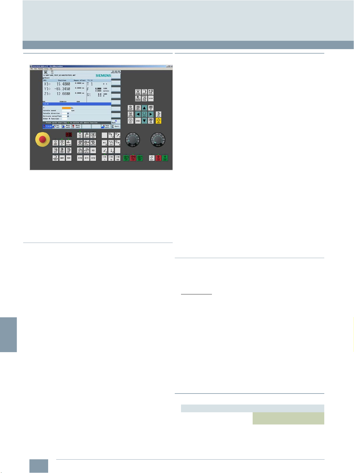
5
© Siemens Industry, Inc. 2018
Services and training
Training
SINUMERIK 808D on PC
■
Overview
SINUMERIK 808D on PC is a PC-based CNC training/CNC programming software package. SINUMERIK 808D on PC enables
completely identical CNC operation and CNC programming as
on SINUMERIK 808D ADVANCED. SINUMERIK 808D on PC
can be used for the following applications:
• Self-study or professional training of
SINUMERIK 808D ADVANCED operation and
CNC programming
• Offline CNC program creation and simulation
• Professional presentation of SINUMERIK 808D ADVANCED
operation and CNC programming
■
Benefits
7 User-friendly, control-identical simulation of operation and
CNC programming of SINUMERIK controls on the PC
7 Maximum compatibility thanks to integrated original
SINUMERIK CNC software
7 Accurate simulation of machine operation with inexpensive
virtual machine control panel
7 Optimum training software for the most common CNC
programming styles – ISO code and SINUMERIK style CNC
programming
7 Easy CNC program exchange via PC and CNC of machine via
USB memory stick
7 The full version of SINUMERIK 808D on PC can be
downloaded free of charge
■
Function
Technologies and machine types
SINUMERIK 808D on PC can be used for the following most
common machine types:
• Vertical machining centers or milling machines with geometry
axes X, Y, Z and a main spindle
• Turning machines with geometry axes X, Z and a main spindle
If the SINUMERIK 808D ADVANCED of the target machine has
been configured with the standard parameters, CNC programs
created with SINUMERIK 808D on PC can be executed on the
machine without any program adaptations.
Accurate simulation of real operator control on the machine
With its fully-fledged virtual machine control panel,
SINUMERIK 808D on PC offers functions such as CNC Start,
CNC Stop, feedrate and spindle override or direction keys and
can therefore be operated just like a real machine.
Online help
Like a SINUMERIK 808D ADVANCED, SINUMERIK 808D on PC
also offers a context-based online help.
Languages
The following languages are available:
•English
• Chinese Simplified
• Russian
• Portuguese
Free download
SINUMERIK 808D on PC can be downloaded free of charge at:
www.cnc4you.siemens.com
■
Integration
SINUMERIK 808D on PC can be used for:
• SINUMERIK 808D ADVANCED T
• SINUMERIK 808D ADVANCED M
Preconditions
Hardware
• PC with 1.5 GHz processor (single core)
•RAM: 1GB
• Hard disk: 2 GB of free memory space
• DVD drive for installation from DVD
• Graphics card: Minimum resolution 640 × 480 pixels
•USB interface
• Mouse, keyboard
Software
• Operating system Windows XP SP3 32 bit Professional/
Home Edition
• Operating system Windows 7 32 bit/64 bit
• Adobe Acrobat Reader
5/4
Siemens NC 81.1 · 2019
■
Selection and ordering data
Description Article No.
SINUMERIK 808D on PC
on DVD-ROM
6FC5870-0YC40-0YT0
Page 73

5
© Siemens Industry, Inc. 2018
Siemens Automation Cooperates with Education (SCE)
Teaching made easy – Comprehensive support on the way to Industrie 4.0
■
Knowledge & technology – the keystones to success in digitalization
Services and training
Digitalization is quickly and radically changing our world.
What does this mean for education?
In the world of Industrie 4.0, companies can expect a host of new
opportunities and challenges. New systems are verified on the
spot through simulations. Automated mass production
processes can make every product on the conveyor belt a
unique product.
■
The SCE digitalization concept for educators
The SCE digitalization concept presented here shows
how digitalization can be implemented in educational
institutions – from vocational schools to universities.
6,08/$7,21 $8720$7,21 &/28'
New products are now market-ready much faster. Siemens is
shaping this transformation as a technology leader in the field of
automation and process lifecycle management (PLM).
These new digitalization processes are changing the know-how
requirements for employees. Many educational institutions are
facing the challenge of conveying Industrie 4.0 know-how as
part of their teaching and training. The Siemens Automation
Cooperates with Education (SCE) program is supporting
educators on the way to Industrie 4.0.
Digitalization (or Industrie 4.0) know-how is now introduced
through CAx and cloud technologies. It is founded on the basics
of automation, such as digital technologies, PLC and information
technologies, and on advanced automation and industrial
communication technologies.
The level of digitalization knowledge can be weighted,
depending on the vocational field or branch of study –
e.g. mechanical engineering, automation engineering or
computer science.
&$[
DQGFORXG
WHFKQRORJLHV
$XWRPDWLRQ
DQGLQGXVWULDO
FRPPXQLFDWLRQ
WHFKQRORJLHV
%DVLFVRI
DXWRPDWLRQ
WHFKQRORJLHV
&RPSXWHUDVVLVWHGWHFKQRORJLHV&$[
9LUWXDOFRPPLVVLRQLQJXVLQJVLPXODWLRQPRGHOV
,QGXVWULDODXWRPDWLRQ
HJGLVWULEXWHG,2+0,5),',2/LQN
GULYHV\VWHPVVDIHW\WHFKQRORJLHV
'LJLWDOWHFKQRORJLHV
%RROHDQIXQFWLRQV
3/&WHFKQRORJLHV
3/&SURJUDPPLQJ
DFFRUGLQJWR,(&
&ORXGWHFKQRORJLHV
&RQQHFWLRQDQGGDWDDQDO\VLVZLWKVPDUWGDWD
PDQXIDFWXULQJH[HFXWLRQV\VWHP0(6DQG
HQWHUSULVHUHVRXUFHSODQQLQJ(53
,QGXVWULDO,7WHFKQRORJLHV
HJ,QGXVWULDO(WKHUQHWLQWHUODFHZLWKVRIWZDUHRI
WKLUGSDUW\SURYLGHUV23&8$VHFXULW\FRPPXQL
FDWLRQQHWZRUNV
,7WHFKQRORJLHV
(WKHUQHWDQGKLJKOHYHOSURJUDP
PLQJODQJXDJHVHJ3\WKRQ
1RGH5('&&/LQX[
Siemens NC 81.1 · 2019
5/5
Page 74

5
© Siemens Industry, Inc. 2018
Services and training
Siemens Automation Cooperates with Education (SCE)
Teaching made easy – Comprehensive support on the way to Industrie 4.0
■
The SCE digitalization concept for educators (continued)
As part of their project work, students at Vocational School 2 in
Wolfsburg, Germany, have implemented the three levels of the
SCE Industrie 4.0 concept. A virtual twin created with the
Siemens NX Mechatronics Designer (MCD) CAD software was
used for the design and virtual commissioning. This enables fast
and efficient assembly of the real automation system, e.g. with
SIMATIC S7-1500/ET 200SP/RFID, for use in classes. Production
data, such as the number of bottles filled, production date and
system parameters, are uploaded to a cloud using SIMATIC
IOT2000.
siemens.com/iot2020
siemens.com/nx
The SCE offers
Learning and training documents
More than 100 didactically prepared learning and training
documents are available through SCE and incorporate the
digitalization concept. They are designed for use in classes,
but can also be customized or used for individual study.
These documents are available for free download, most of them
in 7 languages.
siemens.com/sce/documents
Educator courses
Excellent teaching content is needed to introduce students to
digitalization. For this purpose, SCE holds educator courses in
certain regions. Based on our learning and training documents
and through practical exercises, educators acquire the latest
Industrie 4.0 know-how.
siemens.com/sce/courses
Trainer packages
The 90 SCE trainer packages help educators teaching and
implementing the SCE digitalization concept. Trainer packages
comprise specially compiled, genuine Siemens hardware and
software products. The trainer packages are based on the
learning and training documents and are offered to schools,
colleges and universities at special terms.
siemens.com/sce/tp
Support for your projects / textbooks
We support you on selected projects with advice and assistance
from SCE contact partners.
As a special service, we support textbook authors. We maintain
a list of textbooks on the SCE website.
siemens.com/sce/contact
siemens.com/sce/books
5/6
Siemens NC 81.1 · 2019
Page 75

5
© Siemens Industry, Inc. 2018
Teaching made easy – Comprehensive support on the way to Industrie 4.0
■
Partnerships for proliferation of Industrie 4.0 in education
Services and training
Siemens Automation Cooperates with Education (SCE)
Partnership with WorldSkills
As a technology powerhouse, we support vocational training of
students around the world. Since 2010, we have partnered with
WorldSkills as a Global Industry Partner in order to amplify this
cause.
WorldSkills is an international organization whose mission is to
raise the profile and recognition of skilled people, and show how
important vocational skills are in achieving economic growth and
personal success. Every two years, WorldSkills hosts the world
championships of skills.
Siemens provides the competitors with automation products,
such as SIMATIC S7-1500 and LOGO!, for the disciplines: industrial control, electrical installations, Polymechanics/Automation
and manufacturing technology.
The next international skill competitions are scheduled for
Kazan/Russia, in 2019 and Shanghai/China, in 2021.
Additionally, we support selected continental and regional
competitions.
siemens.com/worldskills
■
Information portal
Partnerships with educators
We provide support to educators and educational organizations
in the form of one-on-one advice through SCE contact partners
and Siemens experts as well as long-term cooperation.
siemens.com/sce/contact
Partnerships with producers of learning systems
For practical training in classrooms and labs, numerous
producers of learning systems offer a wide range of complete
didactic solutions based on SCE trainer packages.
siemens.com/sce/partner
To facilitate your teaching assignment and/or for selfstudy, we
offer educators and students a comprehensive SCE information
portal. At this portal you have quick access to all SCE offers, e.g.
learning and training documents including projects, Getting
Started information, videos, manuals, trial software and
newsletters.
siemens.com/sce
*OREDO,QGXVWU\
3DUWQHURI
:RUOG6NLOOV
,QWHUQDWLRQDO
Siemens NC 81.1 · 2019
5/7
Page 76

5
© Siemens Industry, Inc. 2018
Services and training
Documentation
Specific documentation for SINUMERIK 808D ADVANCED
■
Overview
Comprehensive documentation is available for the
SINUMERIK 808D ADVANCED CNC controls, including the
SINAMICS V70 drive system. This documentation includes
Operator’s Guides, Programming Guides or Configuration
Guides, as well as Installation Guides.
Information is available in the following formats:
• Paper version, printed copy
https://support.industry.siemens.com/cs/ww/en/view/108464614
• PDF file available for download on the Internet at:
www.siemens.com/automation/support
You will find further information on the Internet at:
www.siemens.com/motioncontrol/docu
■
Selection and ordering data
Description
Specific documentation for SINUMERIK 808D ADVANCED
for machine tool manufacturers
SINUMERIK 808D ADVANCED
Commissioning Manual
•English
• Chinese Simplified
SINUMERIK 808D ADVANCED
Function Manual
•English
• Chinese Simplified
SINUMERIK 808D ADVANCED
Parameter Manual
•English
• Chinese Simplified
Specific documentation for SINUMERIK 808D ADVANCED
for users
SINUMERIK 808D ADVANCED
Diagnostics Manual
•English
• Chinese Simplified
SINUMERIK 808D ADVANCED T
Programming and Operating Manual
•English
• Chinese Simplified
SINUMERIK 808D ADVANCED M
Programming and Operating Manual
•English
• Chinese Simplified
SINUMERIK 808D ADVANCED
Manual Machine plus (Turning)
Programming and Operating Manual
•English
• Chinese Simplified
SINUMERIK 808D ADVANCED
Programming and Operating Manual
ISO dialects (Turning and Milling)
•English
• Chinese Simplified
Article No.
6FC5397-4EP10-0BA6
6FC5397-4EP10-0RA6
6FC5397-7EP40-0BA3
6FC5397-7EP40-0RA3
6FC5397-8EP40-0BA3
6FC5397-8EP40-0RA3
6FC5398-6DP10-0BA5
6FC5398-6DP10-0RA5
6FC5398-5DP10-0BA6
6FC5398-5DP10-0RA6
6FC5398-4DP10-0BA6
6FC5398-4DP10-0RA6
6FC5398-3DP10-0BA4
6FC5398-3DP10-0RA4
6FC5398-0DP40-0BA3
6FC5398-0DP40-0RA3
5/8
Siemens NC 81.1 · 2019
Page 77

6
Appendix
© Siemens Industry, Inc. 2018
6/2 Certificates of suitability
6/4 Partners at Siemens
6/4 Siemens Partner Program
6/5 Partner · Industry Mall and
Interactive Catalog CA 01
6/7 Notes on software
6/7 Software licenses
6/9 Setup texts and software update services
6/10 Subject index
6/12 Conversion tables
6/14 Metal surcharges
6/17 Conditions of sale and delivery
6/18 Export regulations
Siemens NC 81.1 · 2019
Page 78

6
© Siemens Industry, Inc. 2018
Appendix
Certificates of suitability
■
Overview
Many of the products in this Catalog fulfill requirements, e.g. for
UL, CSA or FM and are labeled with the corresponding approval
designation.
All of the certificates of suitability, approvals, certificates,
declarations of conformity, test certificates, e.g. CE, UL, Safety
Integrated etc. have been performed with the associated system
components as they are described in the Configuration
Manuals.
Test code Teste d b y Device series/
UL: Underwriters Laboratories
Independent public testing body in North America
UL according to UL standard
UL according to CSA standard
UL according to UL and CSA standards
UL according to UL standard
UL according to CSA standard
UL according to UL and CSA standards
TUV: TUV Rheinland of North America Inc.
Independent public testing body in North America, Nationally Recognized Testing Laboratory (NRTL)
TÜV: TÜV SÜD Product Service
Independent public testing body in Germany, Nationally Recognized Testing Laboratory (NRTL) for North America
TUV according to
UL and CSA standards
Component
SINUMERIK Standard UL 508, CSA C22.2 No. 142 NRAQ/7.E164110
SIMOTION Standard UL 508, CSA C22.2 No. 142 NRAQ/7.E164110
SINAMICS Standard UL 508, 508C, 61800-5-1
SIMODRIVE Standard UL 508C, CSA C22.2 No. 274 NMMS/2/7/8.E192450
SIMOTICS Standard UL 1004-1, 1004-6, 1004-8,
Line/motor reactors Standard UL 508, 506, 5085-1, 5085-2, 1561,
Line filters, dv/dt filters,
sine-wave filters
Resistors UL 508, 508C, CSA C22.2 No. 14, 274 NMTR2/8.E224314
SINAMICS NRTL listing according to standard UL 508C U7V 12 06 20078 013
SIMOTION NRTL listing according to standard UL 508 U7V 13 03 20078 01
SIMODRIVE NRTL listing according to standard UL 508C,
Motion Control Encoder NRTL listing according to UL 61010-1
The certificates are only valid if the products are used with the
described system components, are installed according to the
Installation Guidelines and used for their intended purpose.
In other cases, the vendor of these products is responsible for
arranging for the issue of new certificates.
Test standard Product category/
CSA C22.2 No. 142, 274
CSA C22.2 No. 100
CSA C22.2 No. 14, 47, 66.1-06, 66.2-06
UL 1283, CSA C22.2 No. 8 FOKY2/8.E70122
CSA C22.2. No. 14
CSA C22.2 No. 61010-1
File-No.
NRAQ/7.E217227
NRAQ/7.E164110,
NMMS/2/7/8.E192450,
NMMS/2/7/8.E203250,
NMMS/7.E214113,
NMMS/7.E253831
NMMS/2/7/8.E121068
NMMS/7.E355661
NMMS/7.E323473
NMMS/7.E214113
PRGY2/8.E227215
PRHZ2/8.E93429
PRHJ2/8.E342747
PRGY2/8.E253922
PRHZ2/8.E342746
XQNX2/8.E257859
NMTR2/8.E219022
NMMS2/8.E333628
XPTQ2/8.E257852
XPTQ2/8.E103521
NMMS2/8.E224872
XPTQ2/8.E354316
XPTQ2/8.E198309
XQNX2/8.E475972
NMMS2/8.E192450
NMTR2/8.E221095
NMTR2/8.E226619
U7 11 04 20078 009
U7 11 04 20078 010
U7 11 04 20078 011
CU 72090702
U8V 10 06 20196 024
6/2
Siemens NC 81.1 · 2019
Page 79

6
■
Overview (continued)
Test code Teste d b y Device series/
CSA: Canadian Standards Association
Independent public testing body in Canada
CSA according to CSA standard SINUMERIK Standard CSA C22.2 No. 142 2252-01 : LR 102527
FMRC: Factory Mutual Research Corporation
Independent public testing body in North America
FM according to FM standard SINUMERIK Standard FMRC 3600, FMRC 3611, FMRC 3810,
EAC: Ivanovo-Certificate
Independent public testing body in the Russian Federation
EAC in accordance with the
EAC Directive
RCM: Australian Communications and Media Authority
Independent public testing body in Australia
RCM according to EMC standard SINAMICS
KC: National Radio Research Agency
Independent public testing body in South Korea
KC according to EMC standard SINAMICS
BIA
Federal Institute for Occupational Safety
– Functional safety SINAMICS
TÜV SÜD Rail
– Functional safety SINAMICS
Component
SINAMICS
SINUMERIK
SIMOTION
SINUMERIK
SIMOTION
SINUMERIK
SIMOTION
SINUMERIK
SIMOTION
SINUMERIK
SIMOTION
More information about certificates can be found online at:
https://support.industry.siemens.com/cs/ww/en/ps/cert
© Siemens Industry, Inc. 2018
Test standard Product category/
ANSI/ISA S82.02.1
Standard IEC 61800-5-1/-2, IEC 61800-3 –
Standard IEC AS 61800-3, EN 61800-3 –
Standard KN 11 –
Standard EN 61800-5-2 –
Standard EN 61800-5-2 –
Appendix
Certificates of suitability
File-No.
–
Siemens NC 81.1 · 2019
6/3
Page 80
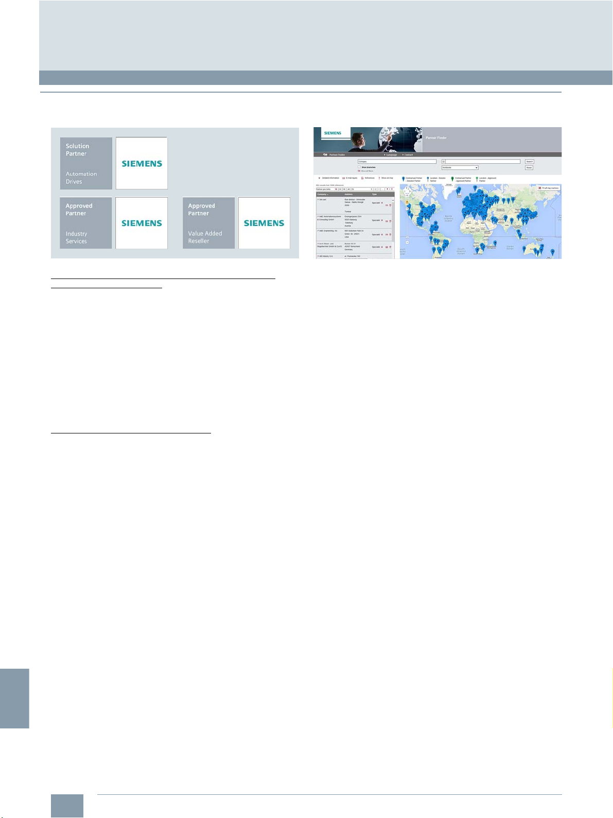
6
Appendix
Partners at Siemens
Siemens Partner Program
■
Overview
Siemens Solution und Approved Partners
© Siemens Industry, Inc. 2018
Partner Finder
Highest competence in automation and drive technology
as well as power distribution
Siemens works closely together with selected partner companies around the world in order to ensure that customer requirements for all aspects of automation and drives, as well as power
distribution, are fulfilled as best as possible wherever you are,
and whatever the time.
We place great value on our customers acting in accordance
with the same ideals which characterize Siemens as a whole:
Competence, professionalism and quality. That is why continuous development through qualification and certification measures in line with global standards is a central aspect of our
Partner Program. This means that with our partners, you benefit
from the same high quality standards all over the world.
The partner emblem is the symbol for tried and tested quality.
Solution Partners and Approved Partners
Our global network of partners includes both Solution Partners
and Approved Partners. The latter can be further differentiated
into "Value Added Reseller" and "Industry Services".
At present we are working with more than 1,500 Solution
Partners worldwide. They are characterized by extensive application, system and sector knowledge, as well as proven project
experience, and are able to implement future-proof tailored
solutions of the highest quality, based on our product and
system portfolio.
With their detailed technical knowledge, Siemens Approved
Partners Value Added Resellers offer a combination of
products and services that range from specialist technologies
and customized modifications to the provision of high-quality
system and product packages. They also provide qualified
technical support and assistance.
Approved Partners Industry Services put their unique exper-
tise entirely at the service of enhancing your productivity and
can be instrumental in ensuring the availability of your plants.
In the Siemens global Solution Partner program, customers are
certain to find the optimum partner for their specific requirements - with no great effort. The Partner Finder is basically a
comprehensive database that showcases the profiles of all our
solution partners.
Easy selection:
Set filters in the search screen form according to the criteria that
are relevant to you. You can also directly enter the name of an
existing partner.
Skills at a glance:
Gain a quick insight into the specific competencies of any
particular partner with the reference reports.
Direct contact option:
Use our electronic query form:
www.siemens.com/partnerfinder
Additional information on the Siemens Solution Partner Program
is available online at:
www.siemens.com/partner-program
6/4
Siemens NC 81.1 · 2019
Page 81
6
Partner at Siemens
© Siemens Industry, Inc. 2018
Appendix
Partner · Industry Mall and Interactive Catalog CA 01
At your service locally, around the globe for consulting, sales,
training, service, support, spare parts on the entire portfolio of
Digital Factory and Process Industries and Drives.
Your partner can be found in our Personal Contacts Database at:
www.siemens.com/automation-contact
You start by selecting
• the required competence,
• products and branches,
• a country and a city
or by a
• location search or free text search.
Easy product selection and ordering in the Industry Mall and with the Interactive Catalog CA 01
Industry Mall
The Industry Mall is a Siemens Internet ordering platform.
Here you have a clear and informative online access to a huge
range of products.
Powerful search functions make it easy to select the required
products. Configurators enable you to configure complex
product and system components quickly and easily. CAx data
types are also provided here.
Data transfer allows the whole procedure, from selection through
ordering to tracking and tracing, to be carried out online. Availability checks, customer-specific discounts and bid creation are
also possible.
www.siemens.com/industrymall
Interactive Catalog CA 01 - Products for Automation and Drives
The Interactive Catalog CA 01 combined with the Siemens
Industry Mall unites the benefits of offline and online media in
one application – the performance of an offline catalog with
the availability of manifold and up-to-date information on the
Internet.
Select products and assemble orders with the CA 01, determine
the availability of the selected products and track & trace via the
Industry Mall.
More information and download:
www.siemens.com/automation/ca01
Siemens NC 81.1 · 2019
6/5
Page 82
6
Appendix
Information and Download Center
Downloading catalogs
© Siemens Industry, Inc. 2018
In the Information and Download Center you can download
catalogs and brochures in PDF format without having to register.
The filter dialog makes it possible to carry out targeted searches.
www.siemens.com/industry/infocenter
6/6
Siemens NC 81.1 · 2019
Page 83

6
© Siemens Industry, Inc. 2018
■
Overview
Software types
Software requiring a license is categorized into types.
The following software types have been defined:
• Engineering software
• Runtime software
Engineering software
This includes all software products for creating (engineering)
user software, e.g. for configuring, programming, parameterizing, testing, commissioning or servicing.
Data generated with engineering software and executable
programs can be duplicated for your own use or for use by
third-parties free-of-charge.
Runtime software
This includes all software products required for plant/machine
operation, e.g. operating system, basic system, system
expansions, drivers, etc.
The duplication of the runtime software and executable programs created with the runtime software for your own use or for
use by third-parties is subject to a charge.
You can find information about license fees according to use in
the ordering data (e.g. in the catalog). Examples of categories of
use include per CPU, per installation, per channel, per instance,
per axis, per control loop, per variable, etc.
Information about extended rights of use for parameterization/configuration tools supplied as integral components of the
scope of delivery can be found in the readme file supplied with
the relevant product(s).
License types
• Floating license
• Single license
• Rental license
• Rental floating license
• Trial license
• Demo license
• Demo floating license
Floating license
The software may be installed for internal use on any number of
devices by the licensee. Only the concurrent user is licensed.
The concurrent user is the person using the program. Use
begins when the software is started.
A license is required for each concurrent user.
Single license
Unlike the floating license, a single license permits only one
installation of the software per license.
The type of use licensed is specified in the ordering data and
in the Certificate of License (CoL). Types of use include for
example per instance, per axis, per channel, etc.
One single license is required for each type of use defined.
Rental license
A rental license supports the sporadic use of engineering
software. Once the license key has been installed, the software
can be used for a specific period of time (the operating hours do
not have to be consecutive).
One license is required for each installation of the software.
Appendix
Notes on software
Software licenses
Rental floating license
The rental floating license corresponds to the rental license,
except that a license is not required for each installation of the
software. Rather, one license is required per object (for example,
user or device).
Trial license
A trial license supports short-term use of the software in a nonproductive context, e.g. for testing and evaluation purposes.
It can be transferred to another license.
Demo license
The demo license support the sporadic use of engineering software in a non-productive context, for example, use for testing
and evaluation purposes. It can be transferred to another
license. After the installation of the license key, the software can
be operated for a specific period of time, whereby usage can be
interrupted as often as required.
One license is required per installation of the software.
Demo floating license
The demo floating license corresponds to the demo license,
except that a license is not required for each installation of the
software. Rather, one license is required per object (for example,
user or device).
Certificate of License (CoL)
The CoL is the licensee's proof that the use of the software has
been licensed by Siemens. A CoL is required for every type of
use and must be kept in a safe place.
Downgrading
The licensee is permitted to use the software or an earlier version/
release of the software, provided that the licensee owns such a
version/release and its use is technically feasible.
Delivery versions
Software is constantly being updated.
The following delivery versions
• PowerPack
• Upgrade
can be used to access updates.
Existing bug fixes are supplied with the ServicePack version.
PowerPack
PowerPacks can be used to upgrade to more powerful software.
The licensee receives a new license agreement and CoL
(Certificate of License) with the PowerPack. This CoL, together
with the CoL for the original product, proves that the new software is licensed.
A separate PowerPack must be purchased for each original
license of the software to be replaced.
Siemens NC 81.1 · 2019
6/7
Page 84

6
© Siemens Industry, Inc. 2018
Appendix
Notes on software
Software licenses
■
Overview
Upgrade
An upgrade permits the use of a new version of the software on
the condition that a license for a previous version of the product
is already held.
The licensee receives a new license agreement and CoL with
the upgrade. This CoL, together with the CoL for the previous
product, proves that the new version is licensed.
A separate upgrade must be purchased for each original license
of the software to be upgraded.
ServicePack
ServicePacks are used to debug existing products.
ServicePacks may be duplicated for use as prescribed according to the number of existing original licenses.
You can download explanations concerning license conditions from:
www.siemens.com/automation/salesmaterial-as/catalog/en/terms_of_trade_en.pdf
License key
Software products with and without license keys are supplied.
The license key serves as an electronic license stamp and
is also the switch for activating the software (floating license,
rental license, etc.).
The complete installation of software products requiring license
keys includes the program to be licensed (the software) and the
license key (which represents the license).
Software Update Service (SUS)
As part of the SUS contract, all software updates for the respective product are made available to you free of charge for a period
of one year from the invoice date. The contract will automatically
be extended for one year if it is not canceled three months
before it expires.
The possession of the current version of the respective software
is a basic condition for entering into an SUS contract.
6/8
Siemens NC 81.1 · 2019
Page 85

6
© Siemens Industry, Inc. 2018
■
Overview
For supplies and deliveries of software products see also
Conditions of sale and delivery.
Legal notes during setup for new software products
All software products feature a uniform reference to the license
conditions. The license conditions are enclosed either with the
documentation or in the software pack. When software is downloaded from the Internet, the license contract is displayed before
the ordering procedure and must be accepted by the user
before downloading can continue.
Notice:
This software is protected by German and/or US copyright laws
and the regulations of international agreements. Unauthorized
reproduction or sale of this software or parts of it is a criminal
offense. This will lead to criminal and civil prosecution, and may
result in significant fines and/or claims for damages. Prior to
installing and using the software, please read the applicable
license conditions for this software. You will find these in the
documentation or packaging.
If you have received this software on a CD-ROM that is marked
Trial version, or accompanying software that is licensed for
your use, the software is only permitted to be used for test and
validation purposes in accordance with the accompanying conditions for the trial license. To this end, it is necessary for programs, software libraries, etc. are installed on your computer. We
therefore urgently recommend that installation is performed on a
single-user computer or on a computer that is not used in the
production process or for storing important data, since it cannot
be completely excluded that existing files will be modified or
overwritten. We accept no liability whatsoever for damage
and/or data losses that result from this installation or the nonobservance of this warning. Every other type of use of this software is only permitted if you are in possession of a valid license
from Siemens is obtained.
If you are not in possession of a valid license that can be proven
by presenting an appropriate Certificate of License/software
product certificate, please abort installation immediately and
contact a Siemens office without delay to avoid claims for
damages.
Appendix
Notes on software
Setup texts and software update services
■
Overview (continued)
Software update services
Order
To order the software update service, an article number must be
specified. The software update service can be ordered when the
software products are ordered or at a later date. Subsequent
orders require that the ordering party is in possession at least of
a single license.
Note:
It is recommended that the software update service is ordered
as early as possible. If a new software version of a software
product is released for delivery by Siemens, only those customers will receive it automatically who are entered in the appropriate delivery list at Siemens at this time. Previous software versions, or the current software version are not supplied when the
software update service is ordered. The software update service
requires that the software product is up-to-date at the time of
completion of the contract for the software update service.
Delivery
When a software update service is ordered, you will be sent the
contractual conditions of this service and the price is due for
payment. At the same time, you will be included in a delivery list
for the software product to be updated. If Siemens releases a
new software version for the corresponding software product
for general sale (function version or product version), it will be
delivered automatically to the goods recipient specified in the
delivery address within the contract period.
■
More information
Security information
Siemens provides products and solutions with industrial security
functions that support the secure operation of plants, systems,
machines and networks. In order to protect plants, systems,
machines and networks against cyber threats, it is necessary to
implement – and continuously maintain – a holistic, state-of-theart industrial security concept. Siemens’ products and solutions
constitute one element of such a concept. Customer are responsible for preventing unauthorized access to theire plants, systems, machines and networks. Such systems, machines and
components should only be connected to an enterprise network
or the internet if and to the extent such a connection is necessary
and only when appropriate security measures (e.g. firewalls
and/or network segmentation) are in place.
For additional information on industrial security measures that
may be implemented, please visit:
https://www.siemens.com/industrialsecurity
Siemens’ products and solutions undergo continuous development to make them more secure. Siemens strongly recommends
that product updates are applied as soon as they are available
and that the latest product versions are used. Use of product
versions that are no longer supported, and failure to apply the
latest updates may increase customer’s exposure to cyber
threats.
To stay informed about product updates, subscribe to the
Siemens Industrial Security RSS Feed under
https://www.siemens.com/industrialsecurity
Siemens NC 81.1 · 2019
6/9
Page 86

6
Appendix
Subject index
© Siemens Industry, Inc. 2018
Numerics Page
1FL6 feed motors ........................................................................1/5, 2/2, 3/12
1PH1 main spindle motors ..........................................................1/5, 2/2, 3/20
A
Absolute encoder ............................................1/5, 3/9, 3/12, 3/13, 3/20, 3/21
Accessories ................................................................................2/3, 3/17, 4/1
Adapter set .................................................................................................4/2
Additional 1 positioning axis/auxiliary spindle......................................2/2, 3/3
Additional NC axis ...............................................................................2/2, 3/3
Advanced Surface ...............................................................................2/4, 3/2
Approvals ....................................................................................................6/2
Auxiliary spindle, 1 additional...............................................................2/2, 3/3
Axis functions ..............................................................................................2/3
Axis/spindle, each additional ...............................................................2/2, 3/3
B
Battery.................................................................................................2/12, 3/2
Bidirectional leadscrew error compensation .....................................2/10, 3/3
Brake cable ...............................................................................................3/29
Bus cable ..................................................................................................3/27
C
Cable set ............................................................................................2/11, 4/5
Cables, pre-assembled ........................................3/26, 3/28, 3/29, 3/31, 3/32
Canned cycles .....................................................................................2/6, 3/2
Certificates of suitability ..............................................................................6/2
Clamp strap ................................................................................................4/8
CNC control ................................................................................................3/2
CNC lock function ..............................................................................2/10, 3/3
CNC programming .....................................................................................2/5
CNC user memory ......................................................................................2/2
Commissioning .........................................................................................2/12
Communication ...........................................................................................2/9
Compensations .........................................................................................2/10
Conditions of sale and delivery ................................................................6/17
Configuration ..............................................................................................2/2
Connectable CNC accessories ..................................................................2/3
Connectable measuring systems ...............................................................2/2
Connection of PLC process signals ...........................................................4/5
Connection overview
• SINAMICS V70 servo drive....................................................................3/29
• SINAMICS V70 spindle drive ................................................................3/31
• SINUMERIK 808D ADVANCED T/M .....................................................3/26
Connection system .....................................................................................1/6
Control configuration ...................................................................................2/2
Control structure .........................................................................................2/2
Contour handwheel ..............................................................................2/3, 3/3
Conversion tables .....................................................................................6/12
CP-Basic ...............................................................................................2/3, 3/3
Cycles .........................................................................................................2/6
D
Data management ......................................................................................2/9
Derating factors for power and signal cables ............................................1/6
Diagnostic functions .................................................................................2/12
Dimensional drawings
• Direct spindle encoder ...........................................................................4/9
• Electronic handwheel .............................................................................4/3
• SIMOTICS M-1PH1 main spindle motor ...............................................3/22
• SIMOTICS S-1FL6 feed motor ..............................................................3/14
• SINAMICS V70 servo drive ...................................................................3/10
• SINAMICS V70 spindle drive ................................................................3/18
D (continued) Page
Dimensional drawings (continued)
• SINUMERIK 808D ADVANCED T/M .......................................................3/4
• SINUMERIK 808D MCP horizontal/vertical ............................................3/7
• SITOP power supply ..............................................................................4/6
• Terminal strip converter ..........................................................................4/5
Direct spindle encoder ........................................................................ 2/2, 4/7
Documentation ........................................................................................... 5/8
Download Center ........................................................................................ 6/6
Downloading Catalogs ............................................................................... 6/6
Drive bus terminator ................................................................................... 3/8
Drives ......................................................................................................... 2/2
E
Electronic handwheel ..........................................................................2/3, 4/2
Encoder ............................................................................... 2/2, 3/8, 3/16, 4/8
Equipment package examples ....................................................... 3/33, 3/34
Export regulations .................................................................................... 6/17
F
Fan kits .......................................................................................................3/8
Feed axis solutions .............................................................................. 1/5, 3/8
Feed motor ............................................................................................... 3/12
Free on-site service .............................................................................1/5, 5/2
G
Generic coupling, CP-Basic.................................................................2/3, 3/3
H
HMI functions ...........................................................................................2/10
I
Incremental encoder .................................................................................. 2/2
Industry Mall ...............................................................................................6/5
Information and Ordering on the Internet ...................................................6/6
Interactive Catalog CA 01 .......................................................................... 6/5
Interpolations .............................................................................................. 2/4
L
License key ................................................................................................6/8
License types .............................................................................................6/7
Lock MyCycles ................................................................................... 2/10, 3/3
M
Machine control panel .........................................................................2/3, 3/5
Main spindle motors .......................................................................... 2/2, 3/20
Maintenance .............................................................................................2/12
Manual ........................................................................................................5/8
Manual Machine plus ...................................................................2/8, 3/2, 3/3
Material warranty .................................................................................1/5, 5/2
Measuring functions ...................................................................................2/4
Measuring systems ....................................................................................2/2
Metal surcharges ...................................................................................... 6/14
MM+ .............................................................................................2/8, 3/2, 3/3
Mode groups ..............................................................................................2/2
Monitoring functions .................................................................................2/10
MOTION-CONNECT .......................................................................... 1/6, 3/26
MOTION-CONNECT cables
• for SINAMICS V70 servo drive .............................................................. 3/21
• for SINAMICS V70 spindle drive .......................................................... 3/31
• for SINUMERIK 808D ADVANCED........................................................3/26
MOTION-CONNECT connection systems .........................................1/6, 3/26
Motion-synchronous actions .......................................................................2/4
6/10
Siemens NC 81.1 · 2019
Page 87

6
© Siemens Industry, Inc. 2018
Appendix
Subject index
O Page
Offline PLC programming tool ..................................................................2/11
Offline programming .................................................................................2/12
On-site service .....................................................................................1/5, 5/2
Open Architecture .......................................................................................2/5
Operating modes ........................................................................................2/8
Operating software languages .................................................................2/10
Operator components ..........................................................................3/5, 4/2
Operator-panel-based CNCs ......................................................................1/4
Options .......................................................................................................3/3
P
Pair of synchronized axes (gantry axes), basic ...................................2/3, 3/3
Partner at Siemens ...............................................................................6/4, 6/5
PC-based CNC training ..............................................................................5/4
PLC area ...................................................................................................2/11
Positioning axis, 1 additional ................................................................2/2, 3/3
Power cable ..............................................................................................3/32
Power supply ..............................................................................................4/6
Program and workpiece management .......................................................2/7
Programming support .................................................................................2/7
R
RS422 (TTL) incremental encoder ................................................2/2, 4/7, 4/8
S
Sample packages.............................................................................3/33, 3/34
Security information ....................................................................................6/9
Serial production .......................................................................................2/12
Service ........................................................................................2/12, 5/1, 5/2
Servo drive ..................................................................................................3/8
Setpoint cable ...........................................................................................3/28
Setup texts ..................................................................................................6/9
Shield plate ...............................................................................................3/17
Siemens Automation Cooperates with Education .......................................5/5
Siemens Solution Partner ............................................................................6/4
Signal cable ............................................................................3/28, 3/29, 3/32
SIMOTICS M-1PH1 main spindle motor ............................................1/5, 3/20
SIMOTICS S-1FL5 feed motor ....................................................................1/5
SIMOTICS S-1FL6 feed motor ...........................................................1/5, 3/12
Simulation ...................................................................................................2/7
SINAMICS V70 .....................................................................................1/5, 3/8
SINAMICS V70 spindle .............................................................................3/16
SINUMERIK 808D ADVANCED ............................................................1/4, 2/1
SINUMERIK 808D ADVANCED M ........................................................1/4, 3/3
SINUMERIK 808D ADVANCED PPU 150.3/160.3 vertical ..........................3/2
SINUMERIK 808D ADVANCED PPU 151.3/161.3 horizontal ......................3/2
SINUMERIK 808D ADVANCED system ...............................................1/3, 3/1
SINUMERIK 808D ADVANCED T .........................................................1/4, 3/3
SINUMERIK 808D CNC controls
• Overview of functions .............................................................................2/1
• Toolbox .........................................................................................2/11, 2/12
S (continued) Page
SINUMERIK 808D MCP ....................................................................... 2/3, 3/5
SINUMERIK 808D MCP horizontal/vertical .................................................3/5
SINUMERIK 808D MCP machine control panel .........................................3/5
SINUMERIK 808D MCP machine control panel, horizontal ........................3/5
SINUMERIK 808D MCP machine control panel, vertical ...........................3/5
SINUMERIK 808D MCP machine control panel,
vertical with handwheel slot .......................................................................3/5
SINUMERIK 808D on PC ................................................................... 2/12, 5/4
SINUMERIK 808D startGUIDE .................................................2/10, 2/12, 3/2
SINUMERIK 808D T/M toolbox ................................................. 2/11, 2/12, 3/3
SINUMERIK Operate BASIC ............................................................... 2/2, 3/2
SINUMERIK programGUIDE BASIC ....................................................2/7, 3/2
SITOP power supply ................................................................................... 4/6
Slot for handwheel ...................................................................................... 3/5
Software licenses ........................................................................................6/7
Software Update Service ..................................................................... 6/8, 6/9
Software version .........................................................................................2/1
Solution Partner ..........................................................................................6/4
Spindle functions ........................................................................................2/4
Spring disk coupling ....................................................................4/7, 4/8, 4/9
Supplementary components ......................................................................4/5
Support, on-site .................................................................................... 1/5, 5/2
SUS ............................................................................................................. 6/8
T
Teaching support ........................................................................................5/5
Technology cycles ...............................................................................2/6, 3/2
Terminal strip converter ..................................................................... 2/11, 4/5
Tools ........................................................................................................... 2/8
Training .............................................................................................. 2/12, 5/3
TRANSMIT/TRACYL Transformation without Y axis ............................. 2/3, 3/3
U
Upgrade ..............................................................................................6/7, 6/8
W
Workpiece management ............................................................................2/7
Siemens NC 81.1 · 2019
6/11
Page 88

6
© Siemens Industry, Inc. 2018
Appendix
Conversion tables
■
Rotary inertia (to convert from A to B, multiply by entry in table)
2
BAlb-in
2
lb-in
2
lb-ft
2
lb-in-s
2
lb-ft-s
2
slug-ft
2
kg-cm
2
kg-cm-s
2
gm-cm
gm-cm-s
2
oz-in
2
oz-in-s
■
Torq ue (to convert from A to B, multiply by entry in table)
16.94 × 10–32.59 × 10–32.15 × 10–42.926 2.98 × 10–32.92 × 1032.984 16 4.14 × 10
144 1 0.3729 3.10 × 10–2421.40 0.4297 4.21 × 105429.71 2304 5.967
386.08 2.681 1 8.33 × 10–21.129 × 1031.152 1.129 × 1061.152 × 1036.177 × 10316
4.63 × 10332.17 12 1 1.35 × 10413.825 1.355 × 1071.38 × 1047.41 × 104192
0.3417 2.37 × 10–38.85 × 10–47.37 × 10–511.019 × 10–31000 1.019 5.46 1.41 × 10
335.1 2.327 0.8679 7.23 × 10–2980.66 1 9.8 × 1051000 5.36 × 10313.887
3.417 × 10–42.37 × 10–68.85 × 10–77.37 × 10–81 × 10
2
0.335 2.32 × 10–38.67 × 10–47.23 × 10–50.9806 1 × 10
0.0625 4.34 × 10–41.61 × 10–41.34 × 10–50.182 1.86 × 10–4182.9 0.186 1 2.59 × 10
24.13 0.1675 6.25 × 10–25.20 × 10–370.615 7.20 × 10–27.09 × 10472.0 386.08 1
BAlb-in lb-ft oz-in N-m kg-cm kg-m gm-cm dyne-cm
lb-ft
2
lb-in-s
2
lb-ft-s
slug-ft
2
2
kg-cm2kg-cm-s2gm-cm
–3
1.01 × 10–611.01 × 10–35.46 × 10–31.41 × 10
–3
980.6 1 5.36 1.38 × 10
2
gm-cm-s2oz-in
2
oz-in-s
2
–2
–2
–5
–2
–3
lb-in 1 8.333 × 10
–2
16 0.113 1.152 1.152 × 10–21.152 × 10
lb-ft 12 1 192 1.355 13.825 0.138 1.382 × 10
oz-in 6.25 × 10
–2
5.208 × 10
–3
17.061 × 10–37.200 × 10
–2
7.200 × 10
–4
72.007 7.061 × 10
N-m 8.850 0.737 141.612 1 10.197 0.102 1.019 × 10
kg-cm 0.8679 7.233 × 10
kg-m 86.796 7.233 1.388 × 10
gm-cm 8.679 × 10
dyne-cm 8.850 × 10
■
Length (to convert from A to B, multiply by entry in table)
–4
–7
7.233 × 10
7.375 × 10
BAinches feet cm yd mm m
inches 1 0.0833 2.54 0.028 25.4 0.0254
feet 12 1 30.48 0.333 304.8 0.3048
cm 0.3937 0.03281 1 1.09 × 10–210 0.01
yd 36 3 91.44 1 914.4 0.914
mm 0.03937 0.00328 0.1 1.09
–2
13.877 9.806 × 10–2110–21000 9.806 × 10
–5
1.388 × 10
–8
1.416 × 10
3
9.806 100 1 1 × 10
–2
9.806 × 10–51 × 10
–5
–7
10
■
Force (to convert from A to B, multiply by entry in table)
–3
1 × 10
–5
1.0197 × 10–61.019 × 10
1 980.665
–8
1.019 × 10
BAlb oz gm dyne N
lb 1 16 453.6 4.448 × 1054.4482
oz 0.0625 1 28.35 2.780 × 1040.27801
gm 2.205 × 10–30.03527 1 1.02 × 10⁻³N.A.
–6
× 10
3.59 × 10–5980.7 1 0.00001
× 10
–3
1 0.001
dyne 2.248
N 0.22481 3.5967 N.A. 100000 1
m 39.37 3.281 100 1.09 1000 1
■
Mass (to convert from A to B, multiply by entry in table)
■
Power (to convert from A to B, multiply by entry in table)
BAhp Watts
hp (English) 1 745.7
(lb-in) (deg./s) 2.645 × 10
(lb-in) (rpm) 1.587 × 10
(lb-ft) (deg./s) 3.173 × 10
(lb-ft) (rpm) 1.904 × 10
Watts 1.341 × 10
–6
–5
–5
–4
–3
1.972 × 10
1.183 × 10
2.366 × 10
0.1420
1
–3
–2
–2
lb 1 16 453.6 0.4536 0.0311
oz 6.25 × 10⁻²¹ 28.35 0.02835 1.93 × 10
gm 2.205 × 10–33.527 × 10–2110–36.852 × 10
kg 2.205 35.27 10
slug 32.17 514.8 1.459 × 10414.59 1
■
Rotation (to convert from A to B, multiply by entry in table)
BAlb oz gm kg slug
BArpm rad/s degrees/s
3
1.129 × 10
4
1.355 × 10
4
1 × 10
5
3
9.806 × 10
–3
1
16.852 × 10
6
7
4
7
5
7
–3
–5
–2
6/12
Siemens NC 81.1 · 2019
rpm 1 0.105 6.0
rad/s 9.55 1 57.30
degrees/s 0.167 1.745 × 10
–2
1
Page 89

6
■
Temperature Conversion
°F °C °C °F
0–17.8–10 14
32 0 0 32
50 10 10 50
70 21.1 20 68
90 32.2 30 86
98.4 37 37 98.4
212 100 100 212
subtract 32 and multiply by 5/9multiply by 9/5 and add 32
■
Mechanism Efficiencies
Acme-screw with brass nut ~0.35–0.65
Acme-screw with plastic nut ~0.50–0.85
Ball-screw ~0.85–0.95
Chain and sprocket ~0.95–0.98
Preloaded ball-screw ~0.75–0.85
Spur or bevel-gears ~0.90
Timing belts ~0.96–0.98
Worm gears ~0.45–0.85
Helical gear (1 reduction) ~0.92
■
Friction Coefficients
Materials
Steel on steel (greased) ~0.15
Plastic on steel ~0.15–0.25
Copper on steel ~0.30
Brass on steel ~0.35
Aluminum on steel ~0.45
Steel on steel ~0.58
Mechanism
Ball bushings <0.001
Linear bearings <0.001
Dove-tail slides ~0.2++
Gibb ways ~0.5++
© Siemens Industry, Inc. 2018
■
Material Densities
Material lb-in
Aluminum 0.096 2.66
Brass 0.299 8.30
Bronze 0.295 8.17
Copper 0.322 8.91
Hard wood 0.029 0.80
Soft wood 0.018 0.48
Plastic 0.040 1.11
Glass 0.079–0.090 2.2–2.5
Titanium 0.163 4.51
Paper 0.025–0.043 0.7–1.2
Polyvinyl chloride 0.047–0.050 1.3–1.4
Rubber 0.033–0.036 0.92–0.99
Silicone rubber, without filler 0.043 1.2
Cast iron, gray 0.274 7.6
Steel 0.280 7.75
■
Wire Gauges
Cross-section
2
mm
0.2 25 24
0.3 23 22
0.5 21 20
0.75 20 19
1.0 19 18
1.5 17 16
2.5 15 13
41311
6129
10 9 7
16 7 6
25 5 3
35 3 2
50 0 1/0
70 000 2/0
95 00000 3/0
120 0000000 4/0
150 – 6/0
185 – 7/0
Appendix
Conversion tables
3
1)
Standard Wire
Gauge (SWG)
3
gm-cm
American Wire
Gauge (AWG)
1)
The table shows approximate SWG/AWG sizes nearest to standard metric
sizes; the cross-sections do not match exactly.
Siemens NC 81.1 · 2019
6/13
Page 90

6
Appendix
Metal surcharges
© Siemens Industry, Inc. 2018
■
Explanation of the raw material/metal surcharges1)
2) 3) 4)
Surcharge calculation
To compensate for variations in the price of the raw materials
silver, copper, aluminum, lead, gold, dysprosium
neodym
2)
, surcharges are calculated on a daily basis using the
2)
and/or
so-called metal factor for products containing these raw
materials. A surcharge for the respective raw material is calculated as a supplement to the price of a product if the basic
official price of the raw material in question is exceeded.
The surcharges are calculated in accordance with the following
criteria:
• Basic official price of the raw material
Basic official price from the day prior to receipt of the order or
prior to release order (daily price) for
3)
- Silver (sales price, processed)
- Gold (sales price, processed)
4)
and for
- Copper (lower DEL notation + 1 %)
- Aluminum (aluminum in cables)
- Lead (lead in cables)
• Metal factor of the products
Certain products are displayed with a metal factor. The metal
factor determines the official price (for those raw materials
concerned) as of which the metal surcharges are applied and
the calculation method used (weight or percentage method).
An exact explanation is given below.
Structure of the metal factor
The metal factor consists of several digits; the first digit indicates
whether the percentage method of calculation refers to the list
price or a possible discounted price (customer net price) (L = list
price / N = customer net price).
The remaining digits indicate the method of calculation used for
the respective raw material. If no surcharge is added for a raw
material, a "-" is used.
1st digit List or customer net price using the percentage method
2nd digit for silver (AG)
3rd digit for copper (CU)
4th digit for aluminum (AL)
5th digit for lead (PB)
6th digit
7th digit
8th digit for neodym (Nd)
for gold (AU)
for dysprosium (Dy)
2)
2)
Weight method
The weight method uses the basic official price, the daily price
and the raw material weight. In order to calculate the surcharge,
the basic official price must be subtracted from the daily price.
The difference is then multiplied by the raw material weight.
The basic official price can be found in the table below using the
number (1 to 9) of the respective digit of the metal factor. The raw
material weight can be found in the respective product descriptions.
Percentage method
Use of the percentage method is indicated by the letters A-Z at
the respective digit of the metal factor.
The surcharge is increased - dependent on the deviation of the
daily price compared with the basic official price - using the percentage method in "steps" and consequently offers surcharges
that remain constant within the framework of this "step range". A
higher percentage rate is charged for each new step. The respective percentage level can be found in the table below.
Metal factor examples
L E A – – – – –
Basis for % surcharge: List price
Silver Basis 150 , Step 50 , 0.5 %
Copper Basis 150 , Step 50 , 0.1 %
No surcharge for aluminum
No surcharge for lead
No surcharge for gold
No surcharge for dysprosium
No surcharge for neodym
N – A 6 – – – –
Basis for % surcharge: Customer net price
No surcharge for silver
Copper Basis 150 , Step 50 , 0.1 %
Aluminum acc. to weight, basic offic. price 225
No surcharge for lead
No surcharge for gold
No surcharge for dysprosium
No surcharge for neodym
– – 3 – – – – –
No basis necessary
No surcharge for silver
Copper acc. to weight, basic official price 150
No surcharge for aluminum
No surcharge for lead
No surcharge for gold
No surcharge for dysprosium
No surcharge for neodym
1)
Refer to the separate explanation on the next page regarding the raw materials dysprosium and neodym (= rare earths).
2)
For a different method of calculation, refer to the separate explanation for these raw materials on the next page.
3)
Source: Umicore, Hanau (www.metalsmanagement.umicore.com).
4)
Source: Schutzvereinigung DEL-Notiz e.V. (www.del-notiz.org).
6/14
Siemens NC 81.1 · 2019
Page 91

6
© Siemens Industry, Inc. 2018
Appendix
Metal surcharges
■
Explanation of the raw material/metal surcharges for dysprosium and neodym (rare earths)1)
Surcharge calculation
To compensate for variations in the price of the raw materials
1)
silver
, copper1), aluminum1), lead1), gold1), dysprosium and/or
neodym, surcharges are calculated on a daily basis using the
so-called metal factor for products containing these raw
materials. The surcharge for dysprosium and neodym is calculated as a supplement to the price of a product if the basic
official price of the raw material in question is exceeded.
The surcharge is calculated in accordance with the following
criteria:
• Basic official price of the raw material
2)
Three-month basic average price (see below) in the period
before the quarter in which the order was received or the release order took place (= average official price) for
- dysprosium (Dy metal, 99 % min. FOB China; USD/kg)
- neodym (Nd metal, 99 % min. FOB China; USD/kg)
• Metal factor of the products
Structure of the metal factor
The metal factor consists of several digits; the first digit is not relevant to the calculation of dysprosium and neodym.
The remaining digits indicate the method of calculation used for
the respective raw material. If no surcharge is added for a raw
material, a "-" is used.
1st digit List or customer net price using the percentage method
2nd digit for silver (AG)
3rd digit for copper (CU)
4th digit for aluminum (AL)
5th digit for lead (PB)
6th digit for gold (AU)
7th digit for dysprosium (Dy)
8th digit for neodym (Nd)
Certain products are displayed with a metal factor. The metal
factor indicates (for those raw materials concerned) the basic
official price as of which the surcharges for dysprosium and
neodym are calculated using the weight method. An exact explanation of the metal factor is given below.
Three-month average price
The prices of rare earths vary according to the foreign currency,
and there is no freely accessible stock exchange listing. This
makes it more difficult for all parties involved to monitor changes
in price. In order to avoid continuous adjustment of the surcharges, but to still ensure fair, transparent pricing, an average
price is calculated over a three-month period using the average
monthly foreign exchange rate from USD to EUR (source: European Central Bank). Since not all facts are immediately available
at the start of each month, a one-month buffer is allowed before
the new average price applies.
Examples of calculation of the average official price:
Period for calculation of
the average price:
Sep 2016 - Nov 2016 Q1 in 2017 (Jan - Mar)
Dec 2016 - Feb 2017 Q2 in 2017 (Apr - Jun)
Mar 2017 - May 2017 Q3 in 2017 (Jul - Sep)
Jun 2017 - Aug 2017 Q4 in 2017 (Oct - Dec)
Period during which the order/release order is
effected and the average price applies:
Weight method
The weight method uses the basic official price, the average
price and the raw material weight. In order to calculate the surcharge, the basic official price must be subtracted from the average price. The difference is then multiplied by the raw material
weight.
The basic official price can be found in the table below using the
number (1 to 9) of the respective digit of the metal factor. Your
Sales contact can inform you of the raw material weight.
Metal factor examples
– – – – – – 7 1
No basis necessary
No surcharge for silver
No surcharge for copper
No surcharge for aluminum
No surcharge for lead
No surcharge for gold
Dysprosium acc. to weight, basic official price
300 €
Neodym acc. to weight, basic official price 50 €
2)
1)
1)
1)
1)
1)
1)
For a different method of calculation, refer to the separate explanation for these raw materials on the previous page.
2)
Source: Asian Metal Ltd (www.asianmetal.com)
Siemens NC 81.1 · 2019
6/15
Page 92

6
© Siemens Industry, Inc. 2018
Appendix
Metal surcharges
■
Values of the metal factor
Percentage
method
A 150 50 0.1 0.2 0.3 0.4 0.1
B 150 50 0.2 0.4 0.6 0.8 0.2
C 150 50 0.3 0.6 0.9 1.2 0.3
D 150 50 0.4 0.8 1.2 1.6 0.4
E 150 50 0.5 1.0 1.5 2.0 0.5
F 150 50 0.6 1.2 1.8 2.4 0.6
G 150 50 1.0 2.0 3.0 4.0 1.0
H 150 50 1.2 2.4 3.6 4.8 1.2
I 150 50 1.6 3.2 4.8 6.4 1.6
J 150 50 1.8 3.6 5.4 7.2 1.8
O 175 50 0.1 0.2 0.3 0.4 0.1
P 175 50 0.2 0.4 0.6 0.8 0.2
R 175 50 0.5 1.0 1.5 2.0 0.5
S 225 50 0.2 0.4 0.6 0.8 0.2
U 225 50 1.0 2.0 3.0 4.0 1.0
V 225 50 1.0 1.5 2.0 3.0 1.0
W 225 50 1.2 2.5 3.5 4.5 1.0
Y 150 25 0.3 0.6 0.9 1.2 0.3
Z 400 25 0.1 0.2 0.3 0.4 0.1
L Calculation based on the list price
N Calculation based on the customer net price (discounted list price)
Weight
method
1 50
2 100
3 150
4 175
5 200
6 225
7 300
8 400
9 555
Miscellaneous
- No metal surcharge
Basic official
price
in €
Price basis (1st digit)
Basic official price in €
Step range
in €
% surcharge
1st step
Price in € Price in € Price in € Price in €
150.01 - 200.00 200.01 - 250.00 250.01 - 300.00 300.01 - 350.00
175.01 - 225.00 225.01 - 275.00 275.01 - 325.00 325.01 - 375.00
225.01 - 275.00 275.01 - 325.00 325.01 - 375.00 375.01 - 425.00
150.01 - 175.00 175.01 - 200.00 200.01 - 225.00 225.01 - 250.00
400.01 - 425.00 425.01 - 450.00 450.01 - 475.00 475.01 - 500.00
% surcharge
2nd step
Calculation based on raw material weight
% surcharge
3rd step
% surcharge
4th step
% sur-
charge
per addi-
tional step
6/16
Siemens NC 81.1 · 2019
Page 93

6
© Siemens Industry, Inc. 2018
■
1. General Provisions
By using this catalog you can acquire hardware and software
products described therein from Siemens AG subject to the
following Terms and Conditions of Sale and Delivery (hereinafter
referred to as "T&C"). Please note that the scope, the quality and
the conditions for supplies and services, including software
products, by any Siemens entity having a registered office
outside Germany, shall be subject exclusively to the General
Terms and Conditions of the respective Siemens entity. The
following T&C apply exclusively for orders placed with Siemens
Aktiengesellschaft, Germany.
1.1 For customers with a seat or registered office in
Germany
For customers with a seat or registered office in Germany, the
following applies subordinate to the T&C:
• for installation work the "General Conditions for Erection
Works Germany"
Deutschland" (only available in German at the moment))
and/or
• for Plant Analytics Services the "Standard Terms and
Conditions for Plant Analytics Services for Customer in
Germany"
Plant Analytics Services für Kunden in Deutschland" (only
available in German at the moment)) and/or
• for stand-alone software products and software products
forming a part of a product or project, the "General License
Conditions for Software Products for Automation and Drives
for Customers with a Seat or registered Office in Germany"
and/or
• for other supplies and/or services the "General Conditions for
the Supply of Products and Services of the Electrical and
Electronics Industry"
In case such supplies and/or services should contain Open
Source Software, the conditions of which shall prevail over the
" General Conditions for the Supply of Products and Services
of the Electrical and Electronics Industry "
contained in the scope of delivery in which the applicable
conditions for Open Source Software are specified. This shall
apply mutatis mutandis for notices referring to other third party
software components.
1.2 For customers with a seat or registered office outside
Germany
For customers with a seat or registered office outside Germany,
the following applies subordinate to the T&C:
• for Plant Analytics Services the "Standard Terms and
Conditions for Plant Analytics Services"
• for services the "International Terms & Conditions for
Services"
Conditions"
•
for other supplies of hard- and/or software the "International
Terms & Conditions for Products"
"Software Licensing Conditions"
1.3 For customers with master or framework agreement
To the extent our supplies and/or services offered are covered
by an existing master or framework agreement, the terms and
conditions of that agreement shall apply instead of T&C.
1)
1)
1)
("Allgemeine Montagebedingungen
("Allgemeine Geschäftsbedingungen für das
1)
.
1)
. A notice will be
1)
and/or
supplemented by "Software Licensing
1)
and/or
1)
supplemented by
1)
Conditions of sale and delivery/Export regulations
■
2. Prices
The prices are in (Euro) ex point of delivery, exclusive of
packaging.
The sales tax (value added tax) is not included in the prices. It
shall be charged separately at the respective rate according to
the applicable statutory legal regulations.
Prices are subject to change without prior notice. We will charget
the prices valid at the time of delivery.
To compensate for variations in the price of raw materials (e.g.
silver, copper, aluminum, lead, gold, dysprosium and neodym),
surcharges are calculated on a daily basis using the so-called
metal factor for products containing these raw materials. A
surcharge for the respective raw material is calculated as a
supplement to the price of a product if the basic official price of
the raw material in question is exceeded.
The metal factor of a product indicates the basic official price
(for those raw materials concerned) as of which the surcharges
on the price of the product are applied, and with what method of
calculation.
You will find a detailed explanation of the metal factor on the
page headed "Metal surcharges".
To calculate the surcharge (except in the cases of dysprosium
and neodym), the official price from the day prior to that on which
the order was received or the release order was effected is used.
To calculate the surcharge applicable to dysprosium and
neodym ("rare earths"), the corresponding three-month basic
average price in the quarter prior to that in which the order was
1)
received or the release order was effected is used with a onemonth buffer (details on the calculation can be found in the
explanation of the metal factor).
■
3. Additional Terms and Conditions
The dimensions are in mm. In Germany, according to the
German law on units in measuring technology, data in inches
apply only to devices for export.
Illustrations are not binding.
Insofar as there are no remarks on the individual pages of this
catalog - especially with regard to data, dimensions and weights
given - these are subject to change without prior notice.
Appendix
1)
The text of the Terms and Conditions of Siemens AG can be
downloaded at
www.siemens.com/automation/salesmaterial-as/catalog/en/
terms_of_trade_en.pdf
Siemens NC 81.1 · 2019
6/17
Page 94

6
© Siemens Industry, Inc. 2018
Appendix
Conditions of sale and delivery/Export regulations
■
4. Export regulations
We shall not be obligated to fulfill any agreement if such
fulfillment is prevented by any impediments arising out of
national or international foreign trade or customs requirements
or any embargoes and/or other sanctions.
Export may be subject to license. We shall indicate in the
delivery details whether licenses are required under German,
European and US export lists.
Our products are controlled by the U.S. Government (when
labeled with "ECCN" unequal "N") and authorized for export only
to the country of ultimate destination for use by the ultimate
consignee or end-user(s) herein identified. They may not be
resold, transferred, or otherwise disposed of, to any other
country or to any person other than the authorized ultimate
consignee or end-user(s), either in their original form or after
being incorporated into other items, without first obtaining
approval from the U.S. Government or as otherwise authorized
by U.S. law and regulations.
The export indications can be viewed in advance in the
description of the respective goods on the Industry Mall, our
online catalog system. Only the export labels "AL" and "ECCN"
indicated on order confirmations, delivery notes and invoices
are authoritative.
Products labeled with "AL" unequal "N" are subject to
European / national export authorization. Products without label,
with label "AL:N" / "ECCN:N", or label "AL:9X9999" /
"ECCN: 9X9999" may require authorization from responsible
authorities depending on the final end-use, or the destination.
If you transfer goods (hardware and/or software and/or
technology as well as corresponding documentation, regardless
of the mode of provision) delivered by us or works and services
(including all kinds of technical support) performed by us to a
third party worldwide, you must comply with all applicable national and international (re-)export control regulations.
If required for the purpose of conducting export control checks,
you (upon request by us) shall promptly provide us with all information pertaining to the particular end customer, final disposition and intended use of goods delivered by us respectively
works and services provided by us, as well as to any export
control restrictions existing in this relation.
The products listed in this catalog may be subject to
European/German and/or US export regulations. Any export
requiring approval is therefore subject to authorization by the
relevant authorities.
Errors excepted and subject to change without prior notice.
6/18
Siemens NC 81.1 · 2019
Page 95

© Siemens Industry, Inc. 2018
Catalogs
Digital Factory, Process Industries and Drives and Energy Management
Further information can be obtained from our branch offices listed at www.siemens.com/automation-contact
Interactive Catalog on DVD Catalog
Products for Automation and Drives
Building Control
GAMMA Building Control ET G1
Drive Systems
SINAMICS G130 Drive Converter Chassis Units
SINAMICS G150 Drive Converter Cabinet Units
SINAMICS GM150, SINAMICS SM150
Medium-Voltage Converters
Digital: SINAMICS PERFECT HARMONY GH180
Medium-Voltage Air-Cooled Drives
(Germany Edition)
SINAMICS G180 Converters – Compact Units, Cabinet
Systems, Cabinet Units Air-Cooled and Liquid-Cooled
SINAMICS S120 Chassis Format Converter Units
SINAMICS S120 Cabinet Modules
SINAMICS S150 Converter Cabinet Units
SINAMICS S120 and SIMOTICS D 21.4
SINAMICS DCM DC Converter, Control Module D23.1
SINAMICS Inverters for
Single-Axis Drives · Built-In Units
SINAMICS Inverters for
Single-Axis Drives · Distributed Inverters
Digital: SINAMICS S210 Servo Drive System D32
Digital: SINAMICS V90 Basic Servo Drive System D33
Digital: SINAMICS G120P and SINAMICS G120P
Cabinet pump, fan, compressor converters
LOHER VARIO High Voltage Motors
Flameproof, Type Series 1PS4, 1PS5, 1MV4 and 1MV5
Frame Size 355 to 1000, Power Range 80 to 7100 kW
Digital: Three-Phase Induction Motors
SIMOTICS HV, SIMOTICS TN
Digital: Three-Phase Induction Motors SIMOTICS HV D84.3
High Voltage Three-phase Induction Motors
SIMOTICS HV Series A-compact PLUS
Digital: Modular Industrial Generators SIGENTICS M D85.1
Three-Phase Induction Motors SIMOTICS HV,
Series H-compact
Synchronous Motors with Permanent-Magnet
Technology, HT-direct
DC Motors DA 12
SIMOVERT PM Modular Converter Systems DA 45
MICROMASTER 420/430/440 Inverters DA 51.2
MICROMASTER 411/COMBIMASTER 411 DA 51.3
Low-Voltage Three-Phase-Motors
SIMOTOCS S-1FG1 Servo geared motors D41
SIMOTICS Low-Voltage Motors D81.1
SIMOTICS FD Low-Voltage Motors D81.8
LOHER Low-Voltage Motors D83.1
Digital: MOTOX Geared Motors D87.1
SIMOGEAR Geared Motors MD 50.1
SIMOGEAR Electric-monorail geared motors
Light-load and heavy-load applications
SIMOGEAR Gearboxes with adapter MD 50.11
Mechanical Driving Machines
FLENDER Standard Couplings MD 10.1
FLENDER High Performance Couplings MD 10.2
FLENDER Backlash-free Couplings MD 10.3
FLENDER SIP Standard industrial planetary gear units MD 31.1
Motion Control
SINUMERIK 840 Equipment for Machine Tools NC 62
SINUMERIK 808 Equipment for Machine Tools NC 81.1
SINUMERIK 828 Equipment for Machine Tools NC 82
SIMOTION Equipment for Production Machines PM 21
Digital: Drive and Control Components for Cranes CR 1
CA 01
D11
D12
D15.1
D18.1
D21.3
D 31.1
D 31.2
D35
D 83.2
D 84.1
D 84.9
D86.1
D86.2
MD 50.8
Process Instrumentation and Analytics
Digital: Field Instruments for Process Automation FI 01
Digital: Display Recorders SIREC D MP 20
Digital: SIPART Controllers and Software MP 31
Products for Weighing Technology WT 10
Digital: Process Analytical Instruments AP 01
Digital: Process Analytics, Components for
Continuous Emission Monitoring
Low-Voltage Power Distribution and
Electrical Installation Technology
SENTRON · SIVACON · ALPHA
Protection, Switching, Measuring and Monitoring
Devices, Switchboards and Distribution Systems
Standards-Compliant Components for
Photovoltaic Plants
Electrical Components for the Railway Industry LV 12
Power Monitoring Made Simple LV 1 4
Components for Industrial Control Panels according
to UL Standards
Digital: Air circuit breakers and molded case circuit
breakers with UL certification
3WT Air Circuit Breakers up to 4000 A LV 3 5
3VT Molded Case Circuit Breakers up to 1600 A LV 36
Digital: SIVACON System Cubicles, System Lighting
and System Air-Conditioning
Digital: ALPHA Distribution Systems LV 5 1
ALPHA FIX Terminal Blocks LV 5 2
SIVACON S4 Power Distribution Boards LV 56
SIVACON 8PS Busbar Trunking Systems LV 7 0
Digital: DELTA Switches and Socket Outlets ET D1
Vacuum Switching Technology and Components for
Medium Voltage
Power Supply
SITOP Power supply KT 10.1
Safety Integrated
Safety Technology for Factory Automation SI 10
SIMATIC HMI / PC-based Automation
Human Machine Interface Systems/
PC-based Automation
SIMATIC Ident
Industrial Identification Systems ID 10
SIMATIC Industrial Automation Systems
Products for Totally Integrated Automation ST 70
SIMATIC PCS 7 Process Control System
System components
SIMATIC PCS 7 Process Control System
Technology components
Add-ons for the SIMATIC PCS 7
Process Control System
SIMATIC S7-400 advanced controller ST 400
SIMATIC NET
Industrial Communication IK PI
SIRIUS Industrial Controls
Digital: SIRIUS Industrial Controls IC 10
Digital: These catalogs are only available as a PDF.
Information and Download Center
Digital versions of the catalogs are available on the Internet at:
www.siemens.com/industry/infocenter
There you’ll find additional catalogs in other languages.
Please note the section “Downloading catalogs” on page
“Online services” in the appendix of this catalog.
Catalog
AP 11
LV 1 0
LV 1 1
LV 1 6
LV 1 8
LV 5 0
HG 11.01
ST 80/
ST PC
ST PCS 7
ST PCS 7 T
ST PCS 7 AO
Page 96

© Siemens Industry, Inc. 2018
Get more information
SINUMERIK CNC systems for machine tools:
www.usa.siemens.com/cnc
The SINAMICS drives family:
www.usa.siemens.com/sinamics
Motion Control Systems and Solutions for production
machine and machine tool equipment:
www.usa.siemens.com/motioncontrol
Local partners worldwide:
www.siemens.com/automation-contact
Siemens Industry, Inc.
Digital Factory – Motion Control
390 Kent Avenue
Elk Grove Village, IL 60007
USA
© Siemens Industry, Inc. 2018
Subject to change without prior notice
Article No. MBCA-NC811-0918
V1.MKKATA.MTS.111
KG 0918 0.3 HOF/DPG 92 En
Printed in Germany
The information provided in this catalog contains merely general
descriptions or characteristics of performance which in case of actual
use do not always apply as described or which may change as a result
of further development of the products. An obligation to provide the
respective characteristics shall only exist if expressly agreed in the
terms of contract. Availability and technical specifications are subject
to change without notice.
All product designations may be trademarks or product names of
Siemens AG or supplier companies whose use by third parties for their
own purposes could violate the rights of the owners.
Security information
Siemens provides products and solutions with industrial
security functions that support the secure operation of
plants, systems, machines and networks.
In order to protect plants, systems, machines and networks
against cyber threats, it is necessary to implement – and
continuously maintain – a holistic, state-of-the-art industrial security concept. Siemens’ products and solutions
constitute one element of such a concept.
Customers are responsible for preventing unauthorized
access to their plants, systems, machines and networks.
Such systems, machines and components should only be
connected to an enterprise network or the internet if and to
the extent such a connection is necessary and only when
appropriate security measures (e.g. firewalls and/or network segmentation) are in place.
For additional information on industrial security measures
that may be implemented, please visit:
usa.siemens.com/industrialsecurity
Siemens’ products and solutions undergo continuous
development to make them more secure. Siemens strongly
recommends that product updates are applied as soon as
they are available and that the latest product versions are
used. Use of product versions that are no longer supported,
and failure to apply the latest updates may increase customer’s exposure to cyber threats.
To stay informed about product updates, subscribe to the
Siemens Industrial Security RSS Feed under:
usa.siemens.com/industrialsecurity
 Loading...