

Siemens SINUMERIK 802D, SINUMERIK 802D sl Training Manual

SINUMERIK 802D solution line
Machine Controller Milling Handbook
Training Manual Edition 2006.7
Training Material

SINUMERIK 802D sl
Operating, Programming
and Service
Milling
Valid for
Control Software
SINUMERIK 802D sl 1.2
Edition 07.2006


Module content for end users.
Operating and Programming
CNC Basic Principles Milling C102
Basic Program Structure C98
Modality (preparatory functions) C89
Commonly used G functions - M C92
Basic Miscellaneous Codes C97
Additional G functions - M C94
Create part program - Milling C77
Cycles - M C99
File Management - CF card C59
Power On and Referencing C69
Axis Control - Jog C82
Control Structure / Navigation C70
MDA - Milling C76
Tools Turning—Milling functions C83
Tools Milling - work planes C72
Work offsets - Milling C74
Automatic C81
RCS 802 Data transfer tool C1
ISO Dialect programming - M C95
Service
Pushbutton test (MCP) C8
LED Diagnosis Drive C9
LED Diagnosis HMI C10
MCPA signal test C11
Save Data Backup C17
Restore Data Backup C18
External data backup and restore C19
Diagnose PLC program C28
Diagnose PLC alarm C31
PLC periphery (HW diagnosis) C32
Alarm structure C37
Editing of NC Machine data C41
Drive Diagnostic parameters C53

SINUMERIK 802D sl Operating and Service Training Manual Page 1
C102
C102
CNC Basic Principles Milling
C102
1 Brief description
Module Objective:
Upon completion of this
module you can understand the basic functionality and requirements of a
CNC controller
Module description:
CNC
machines replicate the functions of a manual machine through the use of a sequential program,
this program replicates the move
ments of a m
anual machine through the so called “CNC program” .
Geometric relationship
s of the component to t
he
machine are achieved with (Tool and component)
numeric compensations. These co
mpensations mat
hematically compensate the dif
ference between
component, Tool and machine.
• Fundamentals of CNC Machines
Module Co
ntent:
Fundamentals of CNC
Machines
Section 2
Notes
SINUMERIK 802D sl Operating and Service Training Manual Page 2
C102
C102
Fundamentals of CNC Machines
Section 2
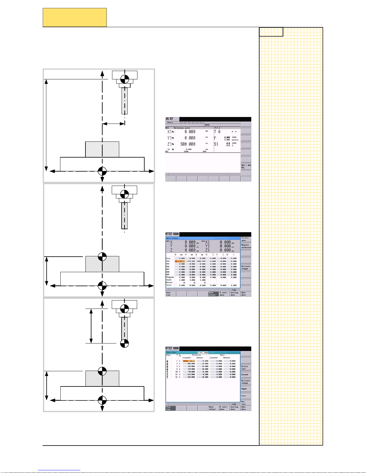
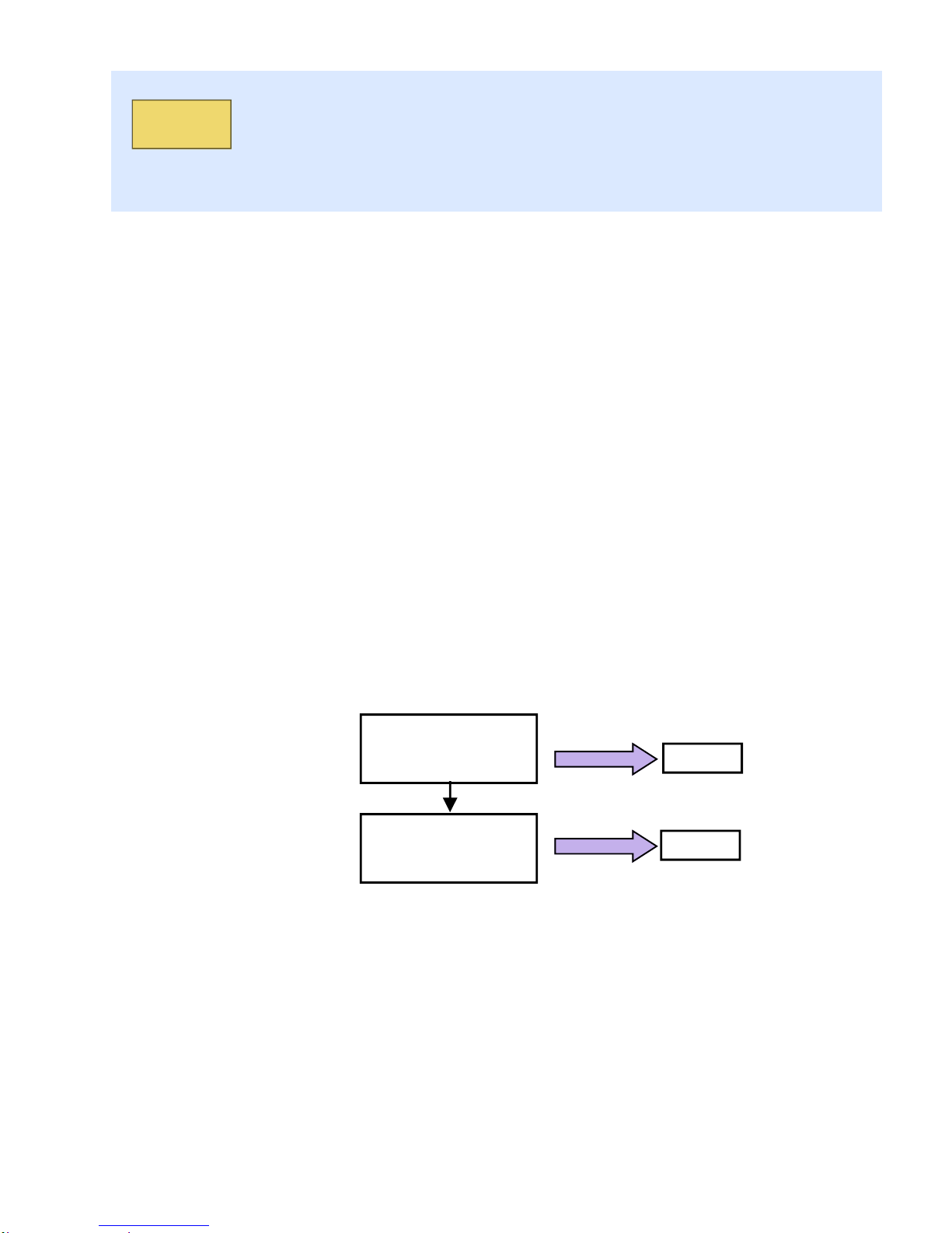
The difference between a Manual machine and a CNC machine is a logical
difference b
ased upon numerical values. This overview module and the
following CNC modules
should help explain the myth of CNC.
ITS ONLY
NUMBERS. No magic !!
Reference position Z
Re
ference position X
Zero Offset
Tool Offset
Zero Offset
SINUMERIK 802D sl Operating and Service Training Manual Page 1
C98
C98
Basic program structure
C98
1 Brief description
• Basic structure
• Basic structure for turning
• Basic structure for milling
Basic structure for
turning
Basic structure for
milling
Section 3
Section 4
Basic structure
Section 2
Module objective:
Upon completion of this
module you will understand the basic structure of an NC program
Module description:
We use a b
asic structure when writing a program to give some kind of order to the program, this will
also help wh
en performing a “Block search”.
Module content:
Notes
SINUMERIK 802D sl Operating and Service Training Manual Page 2
C98
C98
Section 2
Basic structure
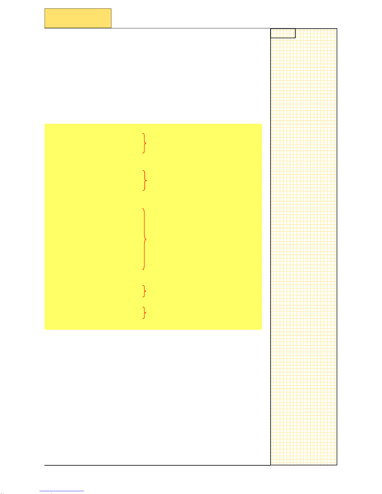
2.1 Basic structure of NC program
There are five basic parts to an NC program.
1.
Basic startup G functions.
2.
Call tool and set spindle speed, feed, coolant.
3.
Set geometry to cut component.
4.
Tool to safe position
5.
End of program
G00 G90 G94 G40 G17
G71
Basic G functions for pr
ogram
T1
M
6
Call tool etc
G95 S1500 F0.15 M08
G00 G54 X0
.0 Y0.0 Z50.0
….
….
….
…
.
Geometry fo
r component
….
….
….
G00 G40 Z5
0.0
X0.0 Y200.0 Z200.0
Safe positio
n for tool change
M30
End of program
You will note that for each tool there is always :
• Call tool etc
• Geometry for component
• Safe position for tool change
This will be t
he same for ever tool that is written in the NC program
If you keep to a good ba
sic structure, this will make the program safer to
run and easier to perform a block search.
Notes
SINUMERIK 802D sl Operating and Service Training Manual Page 3
C98
C98
Section 3
Basic structure for turning
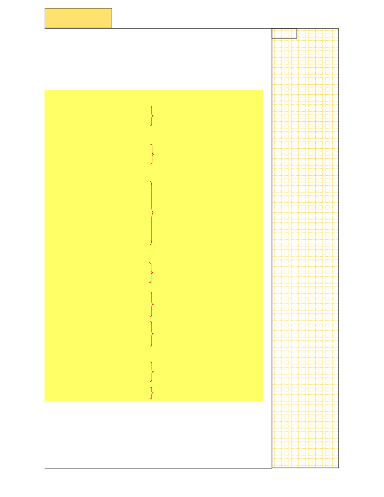
3.1 Basic structure of NC program for turning
N10 G00 G90 G95 G40
G18 G71
N20
LIMS=2500
Basic G functions for pr
ogram
N30 G54
N40 T1 D1
N50
G18
Call tool etc
N60 G96 S2
50 M03 M08
N70 G00 X5
2.0 Z0.1
N80 G01 X-2.0 F0.15
N90 G00 Z2
.0
N100 X20.0
N110 G01 Z
-20.0
Geometry fo
r component
N120 X30.0 Z-25.0
N130 X45.0
N140 Z-50.0
N150 X52.0
N160 G00
G40 Z2.0
N170 X200.0 X1200.0
Safe positio
n for tool change
N180 T4 D1
N190
G17
Call tool etc
N200 G95 S1500 M04 M08
N210 G00 X0.0 Z2.0
N220 G01 Z
-25.0 F0.25
Geometry fo
r component
N230 G00 Z
2.0
N240 G00
G40 Z2.0
N250 X0.0 Z200.0
Safe positio
n for tool change
N260 M30
End of program
Notes
SINUMERIK 802D sl Operating and Service Training Manual Page 4
C98
C98
Section 4
Basic structure for milling
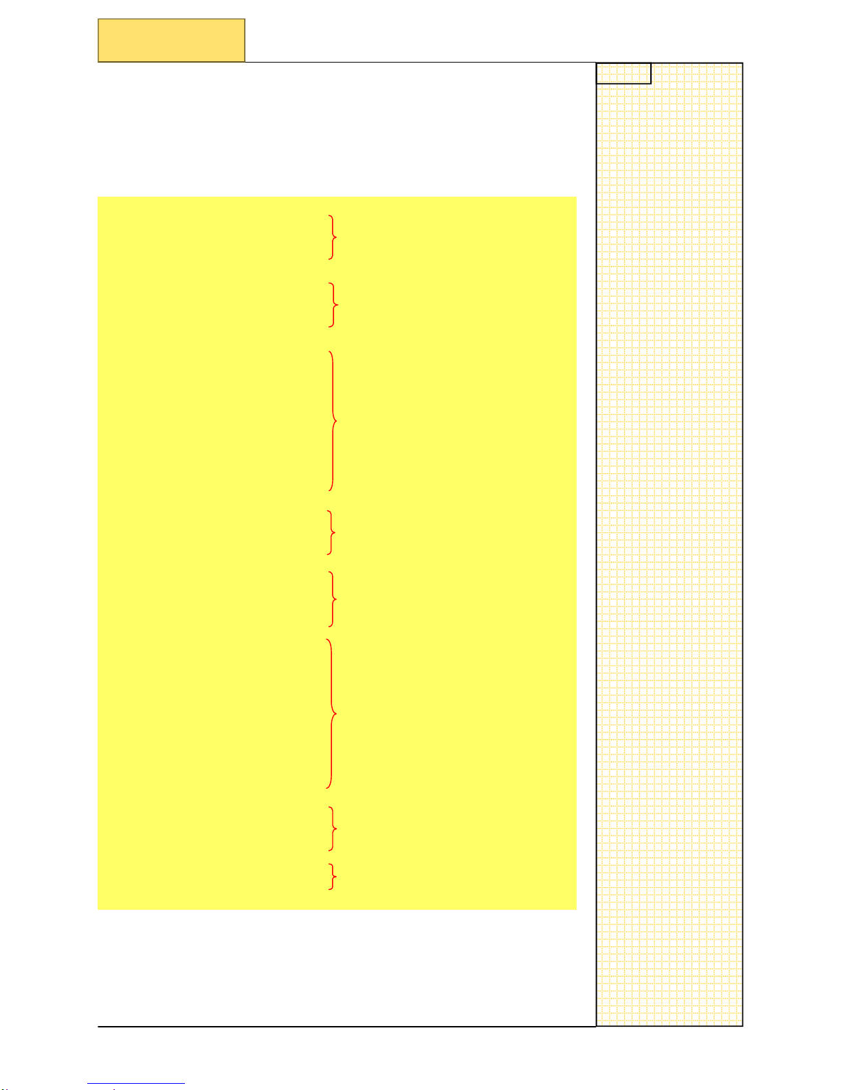
4.1 Basic structure of NC program for milling
N10 G00 G90 G94 G40
G17 G71
Basic G functions for pr
ogram
N20 T1
N30
M6
Call tool etc
N40 G95 S2
500 F0.25 M03 M08
N50 G00 G54 X0.0 Y0.0 Z50.0
N60 MCAL
L CYCLE82(5.0. 0.0, 2.0, -2.0, 0.0, 0.0)
N70 X10.0
N80 X20.0
N90
X20.0
Geometry fo
r component
N100 X30.0
N110 X40.0
N120 X50.0
N130 MCAL
L
N140 G00
G40 Z50.0
N150 X0.0 Y200.0 Z200.0
Safe positio
n for tool change
N160 T4
N170
M06
Call tool etc
N180 G95 S1500 F0.25
M05 M08
N190 G00
G54 X0.0 Y0.0 Z50.0
N200 MCALL CYCLE8
2(5.0. 0.0, 2.
0, -10.0, 0.
0, 0.0)
N210 X10.0
N220 X20.0
N230
X20.0
Geometry fo
r component
N240 X30.0
N250 X40.0
N260 X50.0
N270 MCAL
L
N280 G00
G40 Z50.0
N290 X0.0 Y200.0 Z200.0
Safe positio
n for tool change
N300 M30
End of program
SINUMERIK 802D sl Operating and Service Training Manual Page 1
C89
C89
Modality (Preparatory functions)
C89
1 Brief description
Module objective:
Upon completion of this
module you will understand Preparatory functions (G-Codes).
Module description:
We use pre
paratory G functions according to there appropriate functional group to instruct a machine
what to do via the custo
mers NC program.
Module content:
• G function overview
• G function window display
G function window display
Section 3
G function overview
Section 2
Notes
SINUMERIK 802D sl Operating and Service Training Manual Page 2
C89
C89
Section 2
G function overview
2.1 G function overview
G function (preparatory function).
The G functions are divided into G groups.
Only one G
function from each group can be written in a single block.
A G function can either be modal (until cance
led by another function from
the same group), or non-modal (only effective for that block it is written
in).
Modal example:
G00 G90 G94 G40 G17
T1 D1
G54 S1000 M03
G01 X0.0 Y0.0 Z0.0 F2
00
X
100.0
Y100.0
X0
.0
Y0.0
G00 Z50.0
M30
These blocks are per-
formed at a given feed
rate, because G01 is
modal and will not
change until another
code from the same
group is ent
ered
At this block the speed
of motion will change
due to the change of the
G function group, from
G01 to G00.
Non-modal example:
G00 G90 G94 G40 G17
T2 D1
G54 S1000 M03
X
0.0 Y0.0 Z50.0
G01 Z0.0 F200
G04 F10.0
G00 Z50.0
M30
This G function is only
effective in t
his block, to
use this fun
ction again
you must type it in again
in another block.
Notes
SINUMERIK 802D sl Operating and Service Training Manual Page 3
C89
C89
Section 2
G function overview
Group 1: Modally valid motion commands
Name Meaning
Machine
G00 Rapid
traverse
M/T
G01*# Linear interpolation
M/T
G02 Circular interpolation clockwise
M/T
G03 Circular interpolation counter-clockwise
M/T
G33 Thread cutting with constant lead
M/T
Group 2: Non-modally valid motion, dwell
Name Meaning
Machine
G04
Dwell time preset
M/T
G63 Tapping without synchronization
M/T
G74 Reference point approach with synchronization
M/T
G75 Fixed point approach
M/T
Group 3: Programmable frame, working area limitation
Name Meaning
Machine
TRANS Translation,
programmable
M/T
ROT Rotation, programmable
M/T
SCALE Scaling, programmable
M/T
MIRROR Mirroring, programmable
M/T
G26
Maxi
mum working area limitation/spindle speed limi-
tation
M/T
G25
Minimu
m working area limitation/spindle speed limita-
tion
M/T
Group 6: Plane selection
Name Meaning
Machine
G17#
Plane selection 1st - 2nd geometry axis
M/T
G18* Plane selection 3rd - 1st geometry axis
M/T
G19 Plane selection 2nd - 3rd geometry axis
M/T
Default for turning * / default for milling #
M = milling / T = turnin
g
Notes
SINUMERIK 802D sl Operating and Service Training Manual Page 4
C89
C89
Section 2
G function overview
Group 11: Exact stop, non-modal
Name Meaning
Machine
G09
Velocity reduction, exact positioning
M/T
Group 10: Exact stop - continuous-path mode
Name Meaning
Machine
G60*#
Velocity reduction, exact positioning
M/T
G64 Continuous – path mode
M/T
Group 9: Frame suppression
Name Meaning
Machine
G53
Suppression of current zero offset: including active
settable fra
me G54 - G59
M/T
Group 8: Settable zero offset
Name Meaning
Machine
G500*#
Deactivate all settable G54—G59 if G500 not contain
a value
M/T
G54 Settable zero offset
M/T
G55 Settable zero offset
M/T
G56 Settable zero offset
M/T
G57 Settable zero offset
M/T
G58 Settable zero offset
M/T
G59 Settable zero offset
M/T
Group 7: Tool radius compensation
Name Meaning
machine
G40*#
No tool radius compensation
M/T
G41 Tool radius compensation left of contour
M/T
G42 Tool radius compensation right of contour
M/T
Default for turning * / default for milling #
M = milling / T = turnin
g
Notes
SINUMERIK 802D sl Operating and Service Training Manual Page 5
C89
C89
Section 2
G function overview
Group 16: Feed override on inside and outside curvature
Name Meaning
Machine
CFC*#
Constant feed at contour
M/T
CFTCP Constant feed in tool center point (center-point path)
M/T
CFIN
Constant feed at interna
l radius, acceleration at exter-
nal radius
M/T
Group 15: Feed type
Name Meaning
Machine
G94#
Linear feed mm/min, inch/min
M/T
G95* Rotational feed in mm/rev, inch/rev
M/T
G96 Constant cutting speed (type of feed as for G95) ON
T
G97 Constant cutting speed (type of feed as for G95) OFF
T
Group 14: Workpiece measuring absolute/incremental
Name Meaning
Machine
G90*#
Absolute dimensions input
M/T
G91 Incremental dimension input
M/T
Group 13: Workpiece measuring inch/metric
Name Meaning
Machine
G70
Input system inches (lengths)
M/T
G71*# Input system metric (lengths)
M/T
Default for turning * / default for milling #
M = milling / T = turnin
g
Notes
SINUMERIK 802D sl Operating and Service Training Manual Page 6
C89
C89
Section 3
G function window display
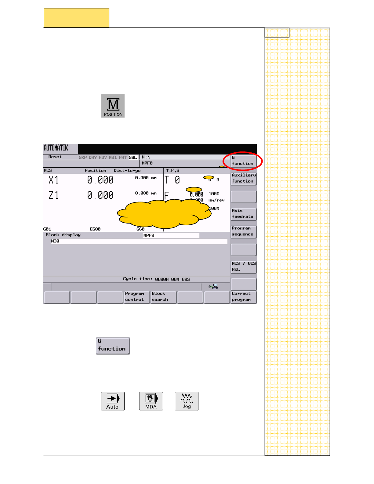
3.1 G function window display
To look at the active G-codes, you can activate a window called
G FUNCTION.
PRES
S
PRESS
This “G function” softkey is present in modes:
Softkey G function
Notes
SINUMERIK 802D sl Operating and Service Training Manual Page 7
C89
C89
Section 3
G function window display
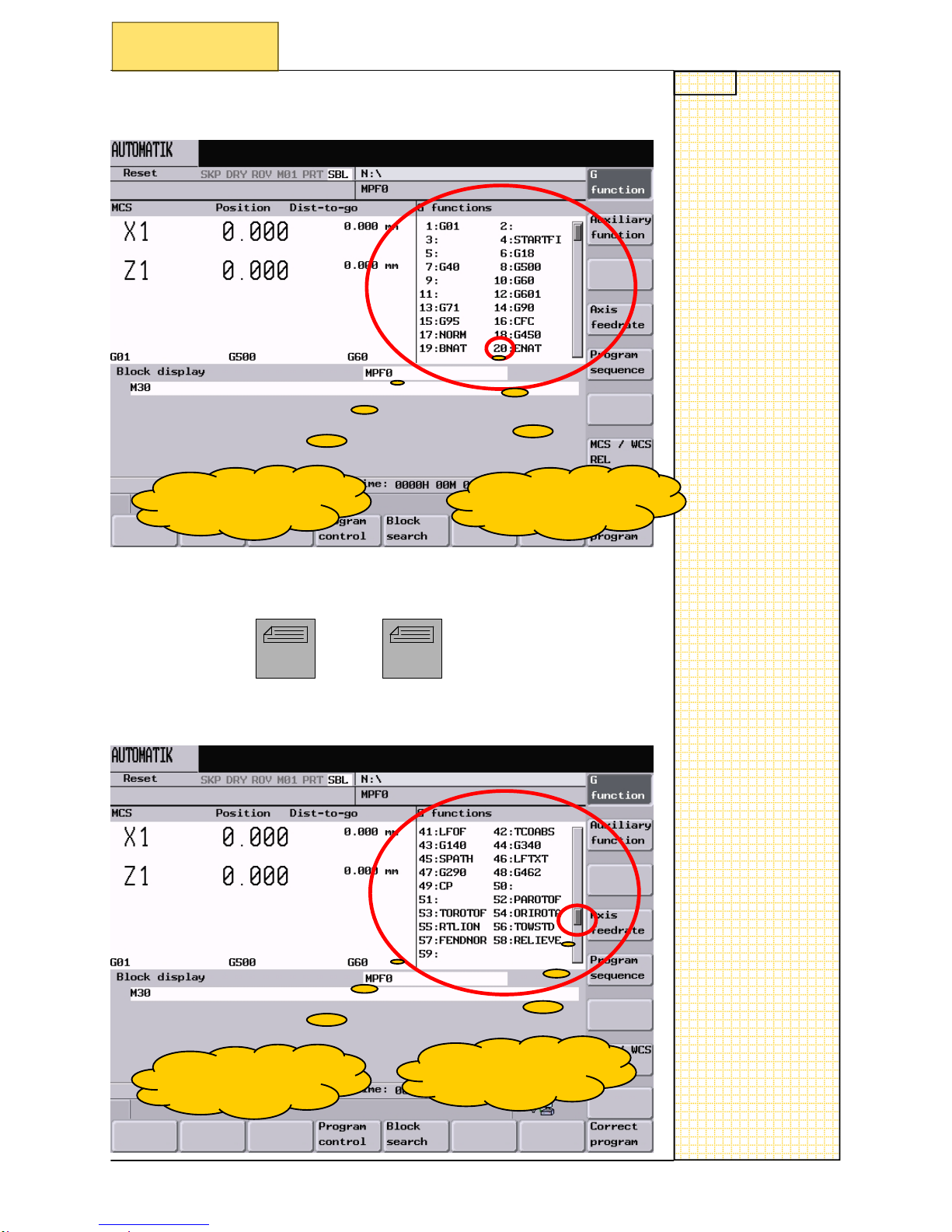
This is what you will see:
This is the window
that is show
n.
In this windo
w, it will show you every group number and the active G-code
for that group at that pre
sent time.
Use the button
to scroll d
own or up to search for the required G-code group.
This shows you the
group number.
Page
up
Page
Do
wn
This is the window
that is show
n.
The slide bar has
now mo
ved.

SINUMERIK 802D sl Operating and Service Training Manual Page 8
C89
C89

SINUMERIK 802D sl Operating and Service Training Manual Page 1
C92
C92
Commonly used G functions Milling
C92
1 Brief description
• G functions in detail
• Example contour program
• Example drilling program
Example contour program
Example drilling program
Section 3
Section 4
G functions in detail
Section 2
Module objective:
Upon completion of this
module you will understa
nd commonl
y used G functions (G-Codes) for mill-
ing in detail.
Module description:
We use G functions a
ccording to their appropriate functional group to instruct a machine what do ,
but a certain
structure should be kept to.
Module content:
Notes
SINUMERIK 802D sl Operating and Service Training Manual Page 2
C92
C92
Section 2
G functions in detail
2.1 G functions “Milling” in detail
Rapid traverse movement G00
Function
You can use
rapid traverse movement, to position the tool rapidly, to
travel around the workpiece or to ap
proach tool change locations.
Note: when there is a tw
o axis movement, both axis interpolate to
their end po
sition, arriving at the same time.
Programming
G00 X
.. Y.. Z..
Or
G0
X.. Y.. Z..
————
—————————————————————————————
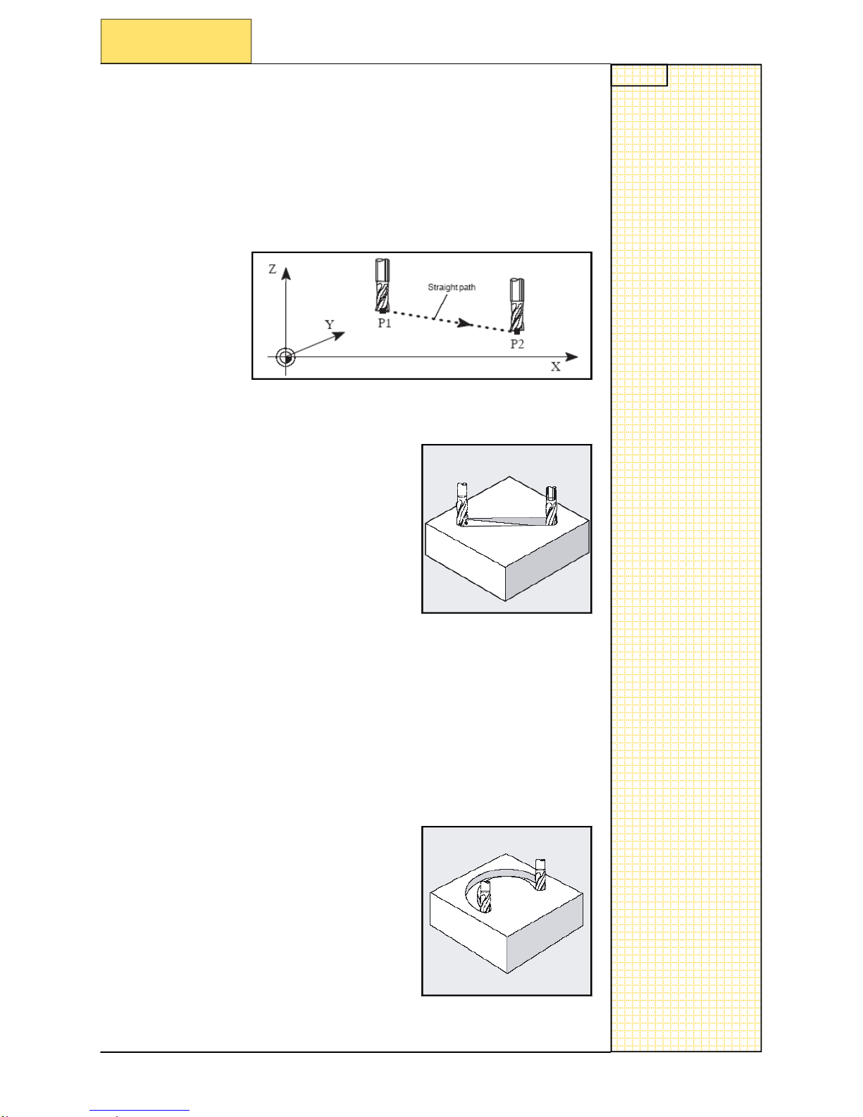
Linear interpolation G01
Function
With G01, the tool travels along a str
aight
line.
Programming
G01 X
.. Y.. Z.. F..
Or
G1
X.. Y.. Z.. F..
————
—————————————————————————————
Circular interpolation, G02/G03
Function
This funct
ion
allows you to program an arc either
in clockwise (G02)
or counter-clockwise (G03) direction.
Programming
G02/G03
X.. Y.. Z.. I=AC(..) J-AC(..) K=AC(..)
absolute ce
ntre point
Or
G02/G03
X.. Y.. Z.. I.. J.. K..
Incremental centre point
Or
G02/G03
X.. Y.. Z.. CR=..
Circle radius CR=
————
—————————————————————————————
Notes
SINUMERIK 802D sl Operating and Service Training Manual Page 3
C92
C92
Dwell time G4
Function
You can use G4 to interrupt workpiece machining between two NC
blocks for the programmed length of time, e.g. dwell at bottom of
hole.
Programming
G4 F.. F = Time
Or
G4 S.. S = Rotations
—————————————————————————————————
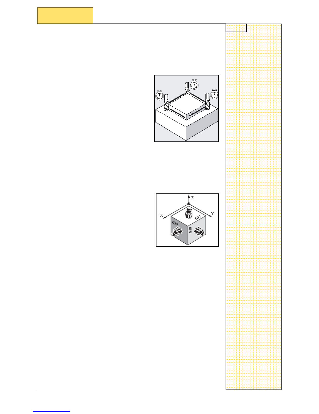
Plane selection G17
Function
To select the infeed feed axis when milling or drilling, this is the default G function.
Programming
G17
—————————————————————————————————
Section 2
G functions in detail
Notes
SINUMERIK 802D sl Operating and Service Training Manual Page 4
C92
C92
Section 2
G functions in detail
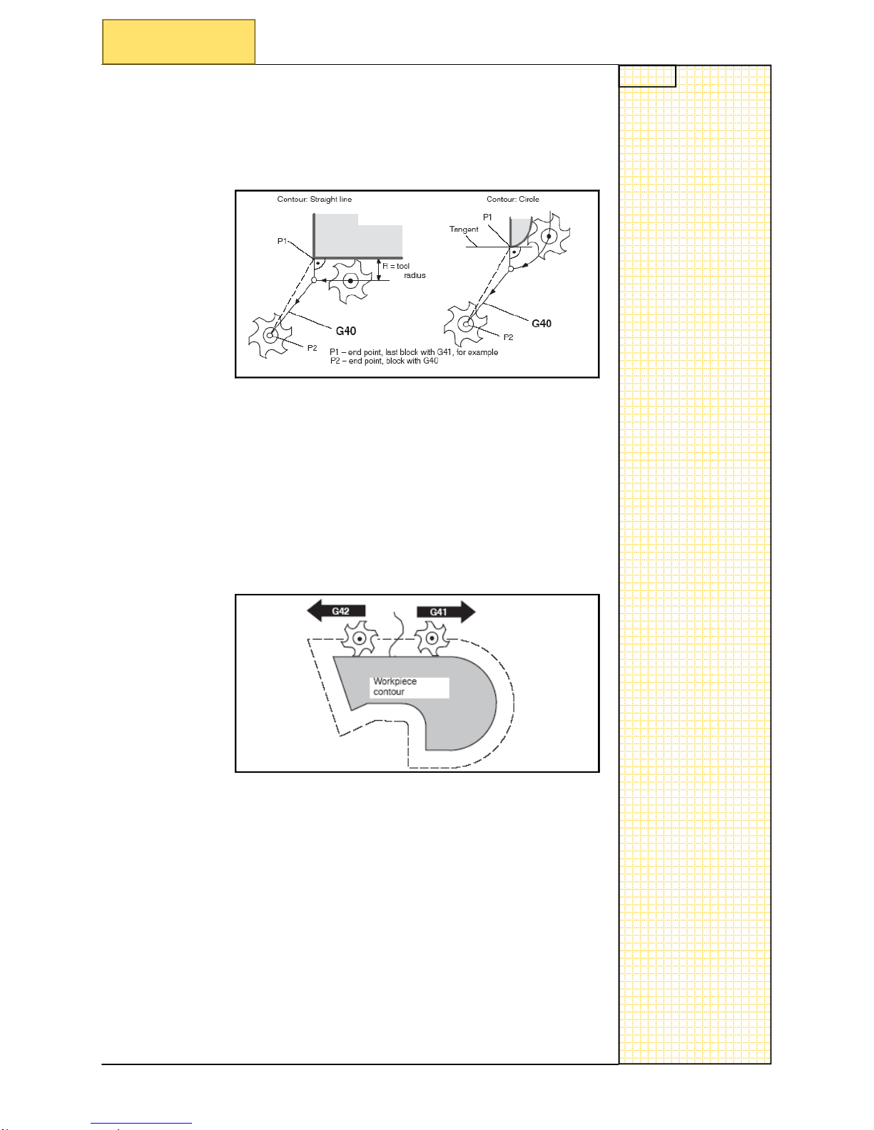
Tool radius compensation G40
Function
To deactivate tool compensation
Programming
G40
————
—————————————————————————————
Tool radius compensation G41
Function
To activate tool compensation, with t
he tool operating to the left of
the contour in the machining directio
n.
Programming
G41
Tool radius compensation G42
Function
To activate tool compensation, with t
he tool operating to the right of
the contour in the machining directio
n.
Programming
G42
————
—————————————————————————————
Notes
SINUMERIK 802D sl Operating and Service Training Manual Page 5
C92
C92
Section 2
G functions in detail
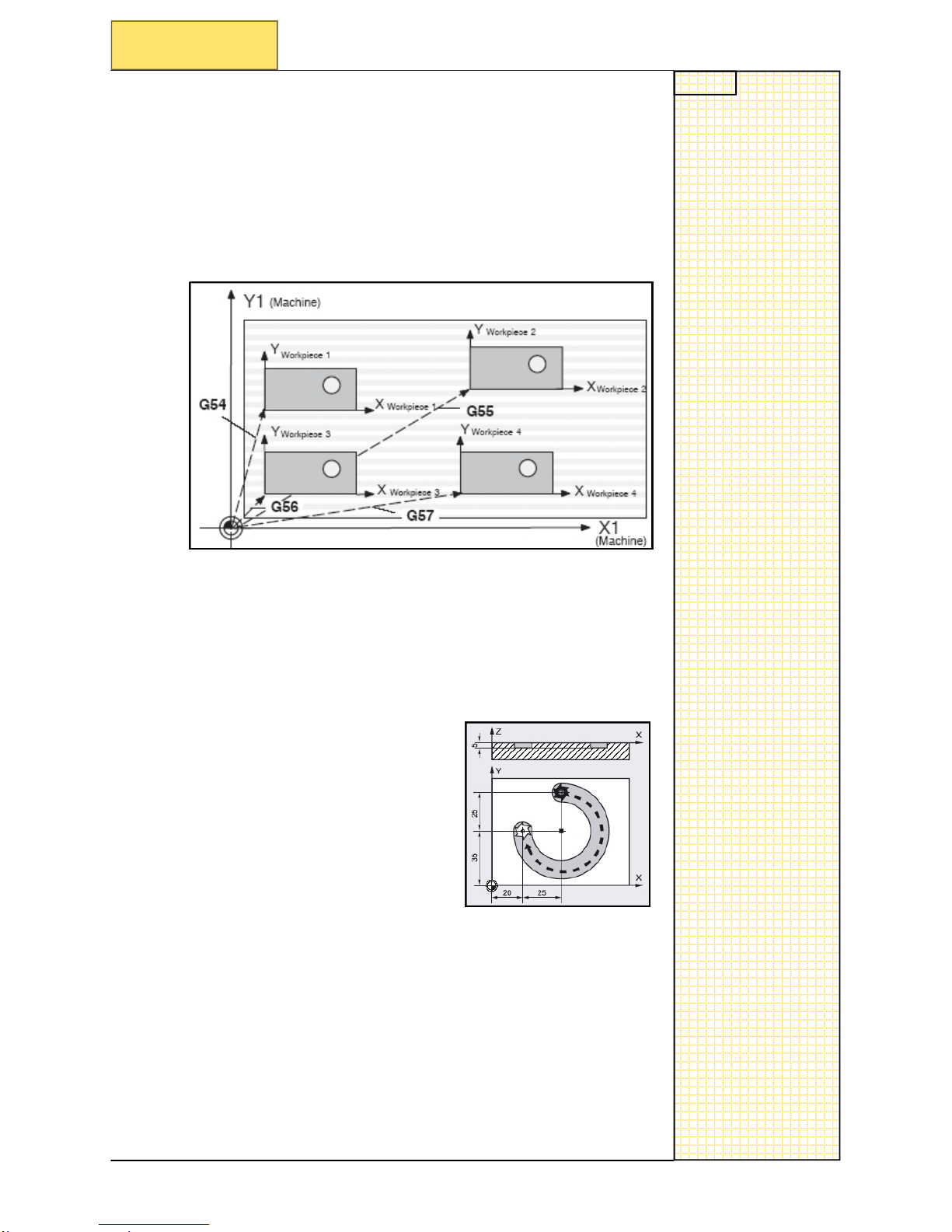
Zero offset G54 to G59
Function
The settable
zero offset re
lates the workpiece zero on all axis
to the
machine zero offset.
Programming
G54 to G59
————
—————————————————————————————
Absolute dimension G90
Function
With the G90 command
all dimensions are related from your active
zero offset.
Programming
G90
X
.. Y.. Z..
————
—————————————————————————————
Notes
SINUMERIK 802D sl Operating and Service Training Manual Page 6
C92
C92
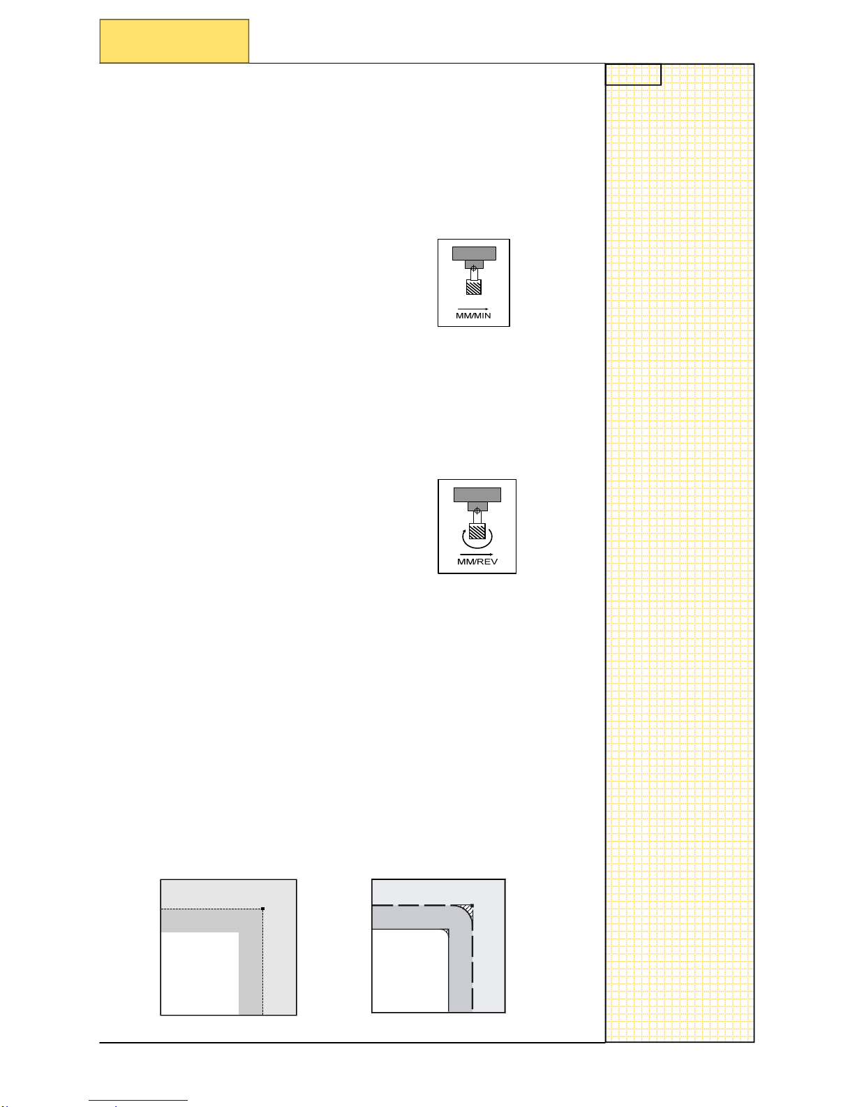
Feed rate G94
Function
This is how the feedrate will act to the axis that is moving in relationship to the spindle.
The spindle will be programmed in direct RPM and the feedrate will
be MM/MIN.
Note: the axis will move without the spindle rotating.
Programming
G94
S.. F..
Feed rate G95
Function
This is how the feedrate will act to the axis that is moving in relationship to the spindle.
The spindle will be programmed in direct RPM and the feedrate will
be REV/MIN.
Programming
G95
S.. F..
Section 2
G functions in detail
Exact stop/continuous-path control: G09, G60, G64
Function
Will set th
e block end behavior movement and to continue with the
next. E.g. G09/G60 the objective for
reaching the exact end position
is to dece
lerate the velocity to zero. With G64, the object is to avoid
deceleration
at the end of the block.
Programming
G09
; Exact stop - non-modal
G60
; Exact stop - modally effective
G64
; Continuous path-control mode
Notes
SINUMERIK 802D sl Operating and Service Training Manual Page 7
C92
C92
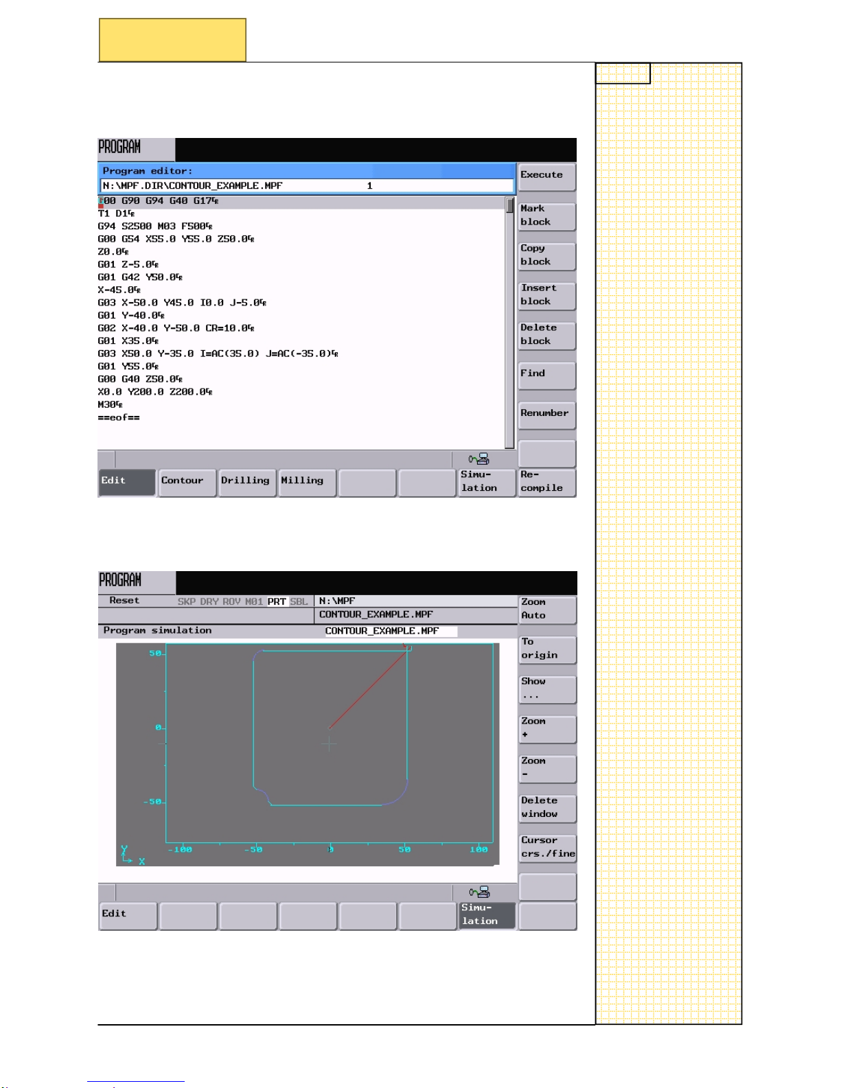
Section 3
Example contour program
G00 G90 G94 G40 G17 ;Basic G-code commands
T1 D1
;call tool
G94 S2500 M03
F500 ;spindle speed in RPM feed MM/MIN
G00 G54 X5
5.0 Y55.0 Z50.0 ;rapid to safe position start of contour
Z0.0
;rapid to safe position
G01 Z-5.0
;feed onto workpiece
G01 G42 Y5
0.0
;apply cutter compensation
X-45
;coordinates for contour
G03 X-50.0
Y45.0 I0.0 J-5.0 ;arc using incremental start point
G01 Y-40.0
;coordinates for contour
G02 X-40.0
Y-50.0 CR=10.0 ;arc using circle radius
G01 X35.0
;coordinates for contour
G03 X50.0 Y-35.0 I=AC(35.0) J=AC(-35.0)
;arc using absolute start point
G01 Y55.0
;coordinates for contour
G00 G40 Z5
0.0 ;rapid to safe
height can
cel cut comp
X0.0 Y200.0 Z200.0
;safe tool change position
M30
;end of program
3.1
Example contour program
Note: G94 are being
used in this
contour
example
Notes
SINUMERIK 802D sl Operating and Service Training Manual Page 8
C92
C92
Section 3
Example contour program
This is the same program typed into the control:
The same program run in simulation
:
Notes
SINUMERIK 802D sl Operating and Service Training Manual Page 9
C92
C92
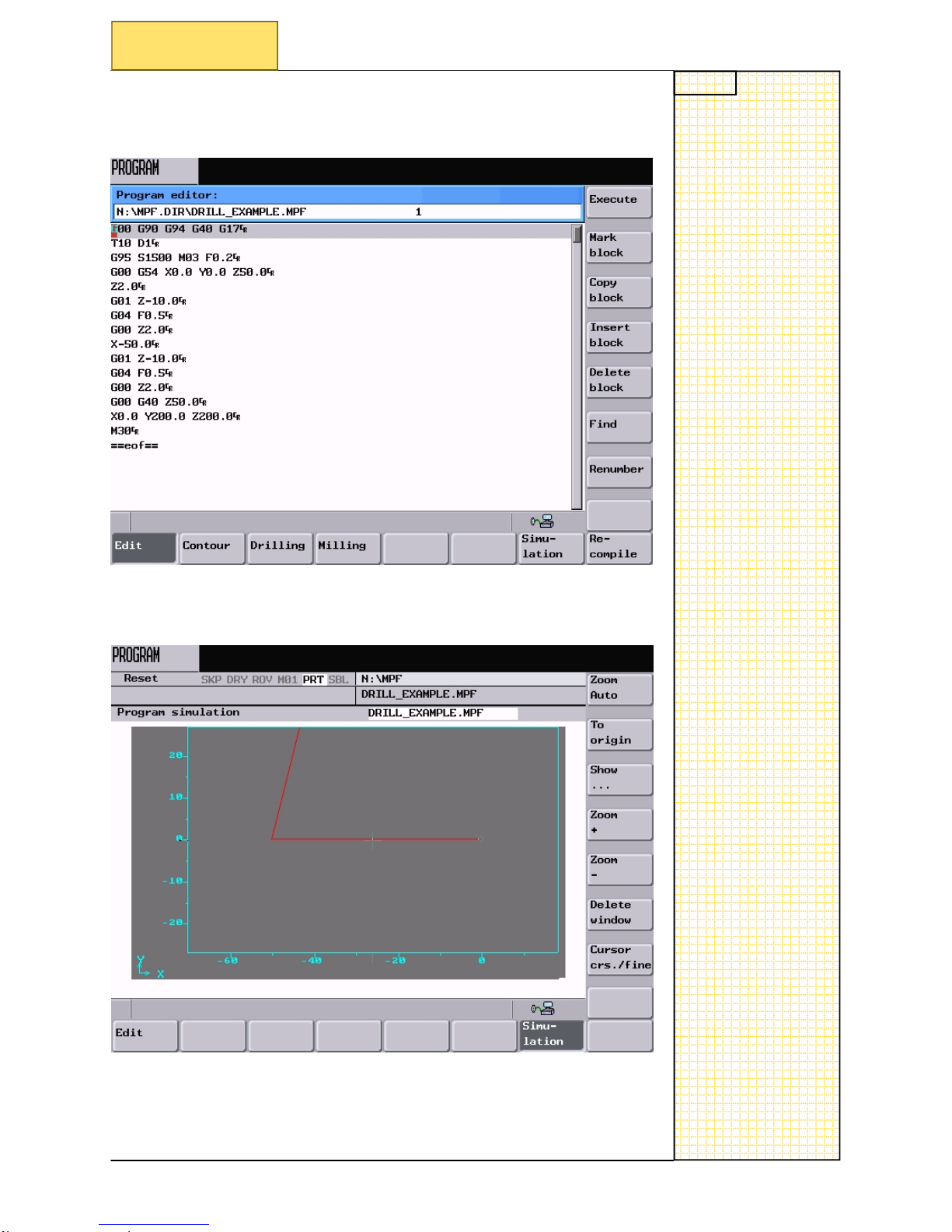
Section 4
Example drilling program
4.1 Example drilling program
G00 G90 G95 G40 G17 ;basic G-code commands
T1 D1
;call tool
G95 S1500 M03
F0.15
;spindle speed in RPM feed MM/REV
G00 G54 X0
.0 Y0.0 Z50.0 ;rapid to safe position start of contour
Z2.0
;rapid to safe position
G01 Z-10.0
;feed onto workpiece
G04 F0.5
;dwell at bottom of hole
G00
Z2.0 ;
rapid out of
hole
X-50
;coordinates for drilling
G01 Z-10.0
;feed onto workpiece
G04 F0.5
;dwell at bottom of hole
G00
Z2.0 ;
rapid out of
hole
G00 G40 Z50.0 ;rapid to safe height
X0.0 Y200.0 Z200.0
;safe tool change position
M30
;end of program
Note: G95 are being
used in this
contour
example
Notes
SINUMERIK 802D sl Operating and Service Training Manual Page 10
C92
C92
The same program run in simulation:
Section 4
Example drilling program
This is the same program typed into the control:
 Loading...