

Page 1

Measuring cycles
_
_
_
_
_
_
_
_
_
_
_
_
SINUMERIK
SINUMERIK 840D sl / 828D
Measuring cycles
Programming Manual
_________________
Preface
_________________
Description
_________________
Measuring variants
_________________
Parameter lists
Changes from cycle version
_________________
SW4.4 and higher
_________________
Appendix
1
2
3
A
B
Valid for:
SINUMERIK 840D sl / 840DE sl / 828D controls
Software CNC software, Version 2.7 SINUMERIK
Operate for PCU/PC Version 2.7
02/2011
6FC5398-4BP40-0BA0
Page 2
Legal information
Legal information
Warning notice system
This manual contains notices you have to observe in order to ensure your personal safety, as well as to prevent
damage to property. The notices referring to your personal safety are highlighted in the manual by a safety alert
symbol, notices referring only to property damage have no safety alert symbol. These notices shown below are
graded according to the degree of danger.
DANGER
indicates that death or severe personal injury will result if proper precautions are not taken.
WARNING
indicates that death or severe personal injury may result if proper precautions are not taken.
CAUTION
with a safety alert symbol, indicates that minor personal injury can result if proper precautions are not taken.
CAUTION
without a safety alert symbol, indicates that property damage can result if proper precautions are not taken.
NOTICE
indicates that an unintended result or situation can occur if the relevant information is not taken into account.
If more than one degree of danger is present, the warning notice representing the highest degree of danger will
be used. A notice warning of injury to persons with a safety alert symbol may also include a warning relating to
property damage.
Qualified Personnel
The product/system described in this documentation may be operated only by personnel qualified for the specific
task in accordance with the relevant documentation, in particular its warning notices and safety instructions.
Qualified personnel are those who, based on their training and experience, are capable of identifying risks and
avoiding potential hazards when working with these products/systems.
Proper use of Siemens products
Note the following:
WARNING
Siemens products may only be used for the applications described in the catalog and in the relevant technical
documentation. If products and components from other manufacturers are used, these must be recommended
or approved by Siemens. Proper transport, storage, installation, assembly, commissioning, operation and
maintenance are required to ensure that the products operate safely and without any problems. The permissible
ambient conditions must be complied with. The information in the relevant documentation must be observed.
Trademarks
All names identified by ® are registered trademarks of Siemens AG. The remaining trademarks in this publication
may be trademarks whose use by third parties for their own purposes could violate the rights of the owner.
Disclaimer of Liability
We have reviewed the contents of this publication to ensure consistency with the hardware and software
described. Since variance cannot be precluded entirely, we cannot guarantee full consistency. However, the
information in this publication is reviewed regularly and any necessary corrections are included in subsequent
editions.
Siemens AG
Industry Sector
Postfach 48 48
90026 NÜRNBERG
GERMANY
Order number: 6FC5398-4BP40-0BA0
Ⓟ 05/2011
Copyright © Siemens AG 2011.
Technical data subject to change
Page 3

Preface
SINUMERIK documentation
The SINUMERIK documentation is organized in the following categories:
● General documentation
● User documentation
● Manufacturer/service documentation
Additional information
You can find information on the following topics at www.siemens.com/motioncontrol/docu:
● Ordering documentation/overview of documentation
● Additional links to download documents
● Using documentation online (find and search in manuals/information)
Please send any questions about the technical documentation (e.g. suggestions for
improvement, corrections) to the following address:
docu.motioncontrol@siemens.com
My Documentation Manager (MDM)
Under the following link you will find information to individually compile OEM-specific
machine documentation based on the Siemens content:
www.siemens.com/mdm
Training
For information about the range of training courses, refer under:
● www.siemens.com/sitrain
SITRAIN - Siemens training for products, systems and solutions in automation technology
● www.siemens.com/sinutrain
SinuTrain - training software for SINUMERIK
FAQs
You can find Frequently Asked Questions in the Service&Support pages under Product
Support. http://support.automation.siemens.com
Measuring cycles
Programming Manual, 02/2011, 6FC5398-4BP40-0BA0
3
Page 4

Preface
SINUMERIK
You can find information on SINUMERIK under the following link:
www.siemens.com/sinumerik
Target group
This programming manual is intended for machine tool programmers for the SINUMERIK
Operate software.
Benefits
With the programming manual, the target group can develop, write, test, and debug
programs and software user interfaces.
Standard scope
This documentation only describes the functionality of the standard version. Additions or
revisions made by the machine manufacturer are documented by the machine manufacturer.
Other functions not described in this documentation might be executable in the control. This
does not, however, represent an obligation to supply such functions with a new control or
when servicing.
For the sake of simplicity, this documentation does not contain all detailed information about
all types of the product and cannot cover every conceivable case of installation, operation, or
maintenance.
Technical Support
You will find telephone numbers for other countries for technical support in the Internet under
http://www.siemens.com/automation/service&support
Measuring cycles
4 Programming Manual, 02/2011, 6FC5398-4BP40-0BA0
Page 5

Table of contents
Preface ...................................................................................................................................................... 3
1 Description................................................................................................................................................. 9
1.1 Basics.............................................................................................................................................9
1.2 General prerequi
1.3 Behavior on block search, dry run, prog
1.4 Reference points on the machine and workpiece........................................................................13
1.5 Definition of the planes, tool types ...............................................................................................15
1.6 Probes that can be used ..............................................................................................................18
1.7 Probe, calibration body, calibration tool
1.7.1 Measuring workpieces on milling machi
1.7.2 Measuring tools on milling machines, machining centers ...........................................................23
1.7.3 Measuring workpieces at the turning mac
1.7.4 Measuring tools at lathes .............................................................................................................28
1.8 Measurement princ
1.9 Measuring strategy for measuring workpi
1.10 Parameters for checking the meas
1.11 Effect of empirical value, mean value, an
1.12 Measuring cycle help programs
1.12.1 CYCLE116: Calculation of center point and radius of a circle.....................................................44
1.12.2 CUST_MEACYC: User program before/after measurements are performed
1.13 Miscellaneous functions...............................................................................................................46
1.13.1 Measuring cycle support in the program
1.13.2 Measuring result screens.............................................................................................................47
sites...................................................................................................................11
ram testing, simulation..................................................12
.......................................................................................22
nes, machining centers.................................................22
hines...........................................................................25
iple.................................................................................................................30
eces with tool offset....................................................35
urement result and offset ......................................................38
d tolerance parameters...............................................43
...................................................................................................44
..............................46
editor............................................................................46
2 Measuring v
2.1 General requirements
2.1.1 Overview of the measuring cycles ...............................................................................................49
2.1.2 Selection of the measuring variants
2.1.3 Selection of the measuring variants
2.1.4 Result parameters........................................................................................................................55
2.2 Measure workpiece (turning) .......................................................................................................56
2.2.1 General information .....................................................................................................................56
2.2.2 Calibrate probe - length
2.2.3 Calibrate probe - radius on s
2.2.4 Calibrate probe - c
2.2.5 Turning measurement - front edge (CYCLE974)
2.2.6 Turning measurement - inside diameter (CYCLE
2.2.7 Turning measurement - outside diameter (CYCLE974,
2.2.8 Extended measurement
Measuring cycles
Programming Manual, 02/2011, 6FC5398-4BP40-0BA0
ariants .................................................................................................................................. 49
..................................................................................................................49
via softkeys (turning) ..........................................................51
via softkeys (milling) ...........................................................53
(CYCLE973)..........................................................................................57
urface (CYCLE973)........................................................................60
alibrate in groove (CYCLE973) ......................................................................63
.........................................................................67
974, CYCLE994) ............................................71
CYCLE994) ..........................................76
...............................................................................................................81
5
Page 6

Table of contents
2.3 Measure workpiece (milling) ....................................................................................................... 83
2.3.1 Calibrate probe - length
2.3.2 Calibrate probe - radius in ring (CYCLE
2.3.3 Calibrate probe - radius on edge (CYCLE976)
2.3.4 Calibrate probe - c
2.3.5 Edge distance - set edge (CYCLE
2.3.6 Edge distance - align edge (CYCLE998)
2.3.7 Edge distance - groove (CYCLE977)
2.3.8 Edge distance - rib (CYCLE977)
2.3.9 Corner - right-angled corner (CY
2.3.10 Corner - any corner (CY
(CYCLE976) ......................................................................................... 83
976) .............................................................................. 86
........................................................................... 90
alibrate on ball (CYCLE976).......................................................................... 93
978)....................................................................................... 96
.................................................................................. 100
........................................................................................ 106
............................................................................................... 110
CLE961) ................................................................................ 114
CLE961) ............................................................................................. 118
2.3.11 Hole - rectangular pocket (CYCLE977) .................................................................................... 122
2.3.12 Hole - 1 hole (CY
2.3.13 Hole - inner circle s
2.3.14 Spigot - rectangular spi
2.3.15 Spigot - 1 circular spigot (CYCLE977)
2.3.16 Spigot - outer circle s
2.3.17 3D - align plane (CY
2.3.18 3D - sphere (CYCLE
2.3.19 3D - 3 spheres (CYCLE997)
2.3.20 3D - kinematic
CLE977) ........................................................................................................ 126
egment (CYCLE979).................................................................................. 130
got (CYCLE977)................................................................................... 134
...................................................................................... 138
egment (CYCLE979)............................................................................... 142
CLE998) ................................................................................................... 146
997).......................................................................................................... 150
..................................................................................................... 154
s (CYCLE996).................................................................................................... 159
2.4 Measure tool (turning)
............................................................................................................... 175
2.4.1 General information................................................................................................................... 175
2.4.2 Calibrate probe (CY
2.4.3 Turning tool (CYCLE
CLE982) .................................................................................................... 178
982).......................................................................................................... 182
2.4.4 Milling tool (CYCLE982)............................................................................................................ 186
2.4.5 Drill (CYCLE
2.4.6 Measure tool with toolholder that c
2.5 Measure tool (milling)
982)....................................................................................................................... 193
an be orientated ................................................................. 198
................................................................................................................ 200
2.5.1 General information................................................................................................................... 200
2.5.2 Calibrate probe (CY
2.5.3 Measure tool (CY
3 Parameter
lists....................................................................................................................................... 215
3.1 Overview of measuring cyc
3.1.1 CYCLE973 measuring cycl
3.1.2 CYCLE974 measuring cycl
3.1.3 CYCLE994 measuring cycl
3.1.4 CYCLE976 measuring cycl
3.1.5 CYCLE978 measuring cycl
3.1.6 CYCLE998 measuring cycl
3.1.7 CYCLE977 measuring cycl
3.1.8 CYCLE961 measuring cycl
3.1.9 CYCLE979 measuring cycl
3.1.10 CYCLE997 measuring cycl
3.1.11 CYCLE996 measuring cycl
3.1.12 CYCLE982 measuring cycl
3.1.13 CYCLE971 measuring cycl
CLE971) .................................................................................................... 202
CLE971)........................................................................................................ 208
le parameters................................................................................. 215
e parameters.................................................................................. 215
e parameters.................................................................................. 218
e parameters.................................................................................. 221
e parameters.................................................................................. 224
e parameters.................................................................................. 226
e parameters.................................................................................. 229
e parameters.................................................................................. 232
e parameters.................................................................................. 235
e parameters.................................................................................. 238
e parameters.................................................................................. 241
e parameters.................................................................................. 244
e parameters.................................................................................. 247
e parameters.................................................................................. 250
3.2 Additional parameters
3.3 Additional result param
Measuring cycles
............................................................................................................... 253
eters ..................................................................................................... 255
6 Programming Manual, 02/2011, 6FC5398-4BP40-0BA0
Page 7

Table of contents
3.4 Parameter ..................................................................................................................................256
A Changes from cycle versi
A.1 Assignment of the measuring cycle para
A.2 Changes in the machine and s
A.3 Complete overview of the changed cycl
A.4 Comparing GUD parameters
A.5 GUD variables that can no longer be used
A.6 Changes to names of cycle program
on SW4.4 and higher ..................................................................................... 257
meters to MEA_FUNCTION_MASK parameters.......257
etting data from SW 4.4 ............................................................260
e machine and cycle setting data ...............................261
(regarding measuring functions).................................................263
................................................................................267
s and GUD modules ........................................................269
B Appendix................................................................................................................................................ 271
B.1 Abbreviations .............................................................................................................................271
B.2 Documentation overview............................................................................................................272
Glossary ................................................................................................................................................ 273
Index...................................................................................................................................................... 279
Measuring cycles
Programming Manual, 02/2011, 6FC5398-4BP40-0BA0
7
Page 8

Table of contents
Measuring cycles
8 Programming Manual, 02/2011, 6FC5398-4BP40-0BA0
Page 9
Description
1.1 Basics
General information
Measuring cycles are general subroutines designed to solve specific measurement tasks.
They can be adapted to specific problems via parameter settings.
When taking general measurements, a distinction is made between
● Tool measurement and
● Workpiece measurement.
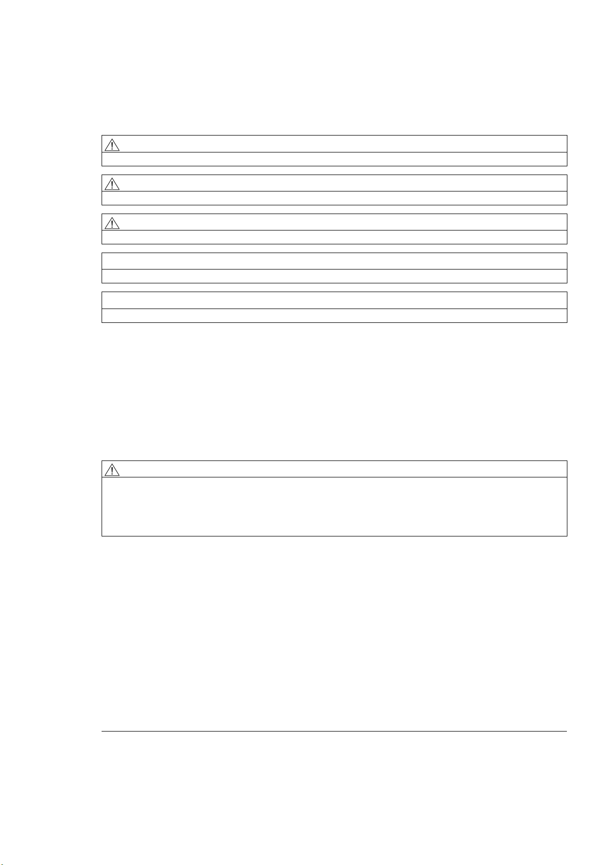
Workpiece measurement
;
1
)
=
<
:
:
Workpiece measurement, turning example
In workpiece measurement, a probe is moved up to the clamped workpiece in the same way
as a tool and the measured values are acquired. The flexibility of measuring cycles makes it
possible to perform nearly all measurements required on a milling or turning machine.
The result of the workpiece measurement can be optionally used as follows:
● Compensation in the work offset
● Automatic tool offset
● Measurement without offset
=
Workpiece measurement, milling example
;
Measuring cycles
Programming Manual, 02/2011, 6FC5398-4BP40-0BA0
9
Page 10
Description
1.1 Basics
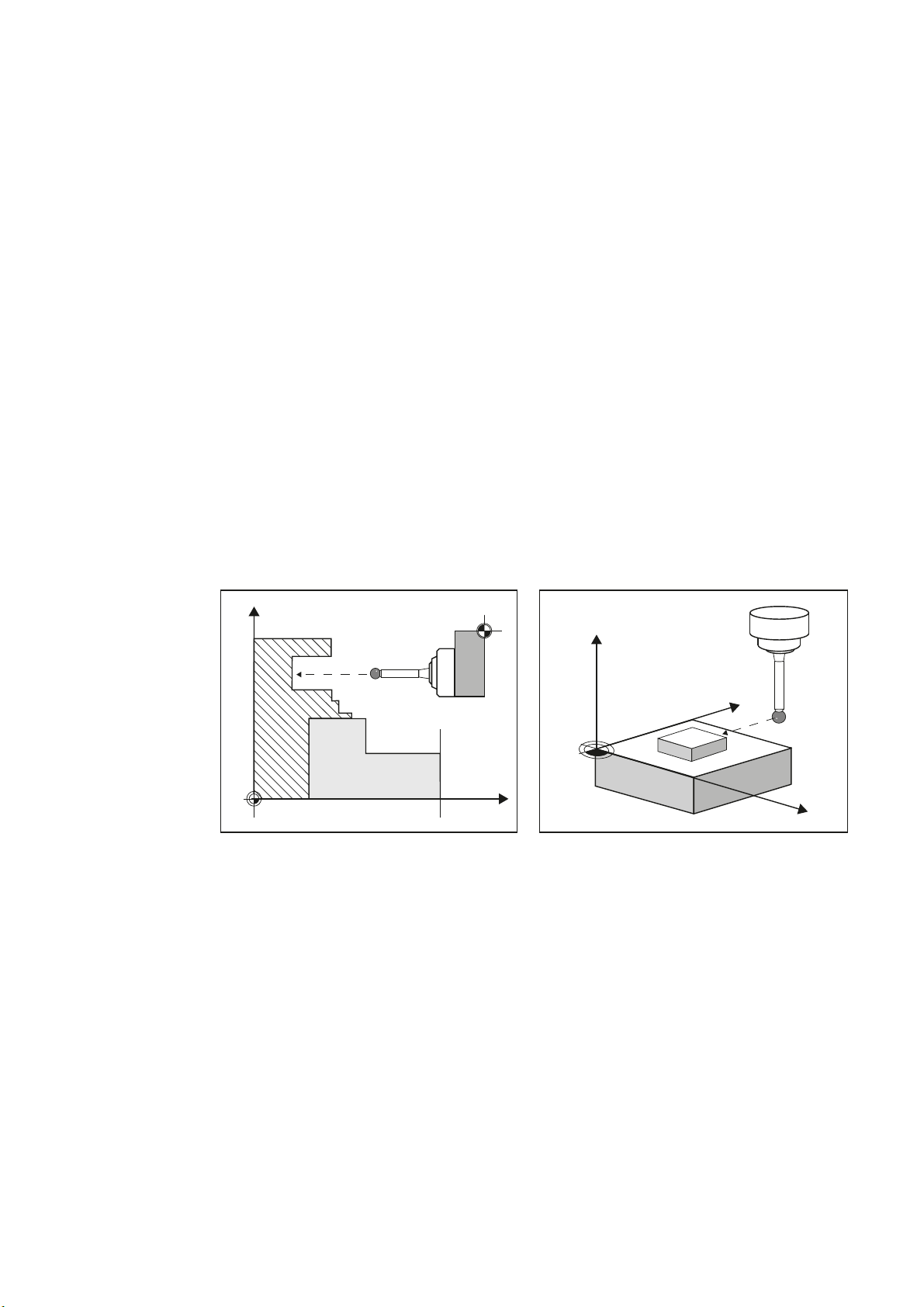
Tool measurement
;
=
Tool measurement, turning tool example
=
<
;
Tool measurement, drill example
In tool measurement, the selected tool is moved up to the probe and the measured values
are acquired. The probe is either in a fixed position or is swung into the working area with a
mechanism. The tool geometry measured is entered in the appropriate tool offset data set.
Measuring cycles
10 Programming Manual, 02/2011, 6FC5398-4BP40-0BA0
Page 11

Description
1.2 General prerequisites
1.2 General prerequisites
Certain preconditions must be met before measuring cycles can be used. These are
described in detail in the
Check the preconditions using the following checklist:
● Machine
– All machine axes are designed in accordance with DIN 66217.
– Machine data has been adapted.
● Starting position
– The reference points have been approached.
– The starting position can be reached by linear interpolation without collision.
● Display functions of the measuring cycles
A HMI/PCU or HMI/TCU is required for showing the measuring result displays and for
measuring cycle support.
● Please observe the following when programming:
SINUMERIK 840D sl Base Software and Operating Software
.
References
– Tool radius compensation is deselected before it is called (G40).
– The cycle is called no later than at the 5th program level.
– The measurement is also possible in a system of units that differs from the basic
system (with technology data that has been switched over).
For metric dimension system with active G70, G700.
For inch dimension system with active G71, G710.
Supplementary information for this documentation is provided in the following manuals:
● Commissioning Manual
– /IM9/ SINUMERIK Operate
● /PG/, Programming Manual
● /FB1/, Function Manual
● /FB2/, Function Manual
● /FB3/, Function Manual
SINUMERIK 840D sl Base Software and Operating Software
SINUMERIK 840D sl / 828D Fundamentals
Basic Functions
Expanded Functions
Special Functions
Measuring cycles
Programming Manual, 02/2011, 6FC5398-4BP40-0BA0
11
Page 12

Description
1.3 Behavior on block search, dry run, program testing, simulation
1.3 Behavior on block search, dry run, program testing, simulation
Function
The measuring cycles are skipped during execution if one of the following execution modes
is active:
"Trial run"
($P_DRYRUN=1)
Simulation
"Program test"
"Block search"
The simulation of the measuring cycles is realized in the user interface (HMI) in the "Program
Editor" area.
Following settings are possible in the channel-specific setting data SD 55618:
● SD 55618 $SCS_MEA_SIM_ENABLE = 0
The measuring cycle is skipped, the HMI simulation shows no path motion of the probe.
● SD 55618 $SCS_MEA_SIM_ENABLE = 1
The measuring cycle is executed, the HMI simulation shows the corresponding path
motion of the probe.
No measurements, tool or work offsets are made.
Actived functions such as "measuring result display" or "travel with collision monitoring"
are not implemented.
($P_ISTEST=1)
($P_SEARCH=1), only if $A_PROTO=0.
Measuring cycles
12 Programming Manual, 02/2011, 6FC5398-4BP40-0BA0
Page 13
Description
1.4 Reference points on the machine and workpiece
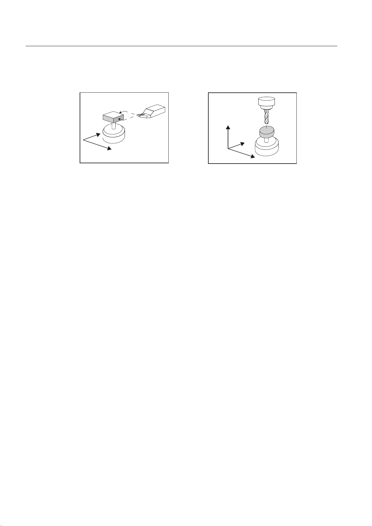
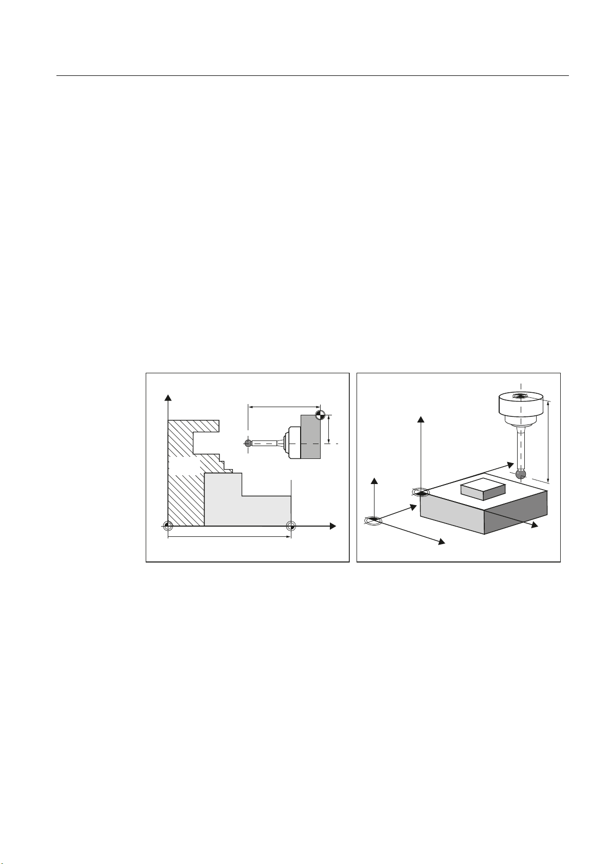
1.4 Reference points on the machine and workpiece
General information
Depending on the measuring task, measured values may be required in the machine
coordinate system (MCS) or in the workpiece coordinate system (WCS).
For example: It may be easier to ascertain the tool length in the machine coordinate system.
Workpiece dimensions are measured in the workpiece coordinate system.
Where:
● M = machine zero in the machine coordinate system
● W = workpiece zero in the workpiece coordinate system
● F = Tool reference point
Reference points
;
0
6SLQGOH
FKXFN
:RUNSLHFH
:2LQ=
/
)
/
;
:
==
=
0
=
<
:
<
;
)
/
;
The position of tool reference point F in the machine coordinate system is defined with
machine zero M as the machine actual value.
The position of the tip/cutting edge of the active tool in the workpiece coordinate system is
displayed with the workpiece zero W as workpiece actual value. For a workpiece probe, the
center or the end of the probe ball can be defined as the tool tip.
The work offset (WO) characterizes the position of the workpiece zero W in the machine
coordinate system.
Work offsets (WO) comprise the components offset, rotation, mirroring and scaling factor
(only the global basis work offset does not contain any rotation).
Measuring cycles
Programming Manual, 02/2011, 6FC5398-4BP40-0BA0
13
Page 14

Description
1.4 Reference points on the machine and workpiece
A distinction is made between the basis, work offset (G54 ... G599) and programmable work
offset. The basic area contains further subsections – such as the basic work offset, channelspecific basic work offset and configuration-dependent work offsets (e.g. rotary table
reference or basic reference).
The specified work offsets are effective together as chain and result in the workpiece
coordinate system.
Note
Scale factors with a scaling value unequal to "1" are not supported by the measuring cycles!
Mirroring functions are only permitted in conjunction with counterspindles on lathes.
The machine and workpiece coordinate system can be set and programmed separately in
the "inch" or "metric" system of units (G70/G71).
Note
Transformation
Measure workpiece
Workpiece measurements are always performed in the workpiece coordinate system. All
descriptions relating to workpiece measurement refer to it!
Measure tool
When measuring tools with kinematic transformation active, a distinction is made
between basic coordinate system and machine coordinate system.
If kinematic transformation is deactivated, this distinction is made.
All subsequent descriptions relating to tool measurement assume that kinematic
transformation is disabled and therefore refer to the machine coordinate system.
Measuring cycles
14 Programming Manual, 02/2011, 6FC5398-4BP40-0BA0
Page 15
Description
1.5 Definition of the planes, tool types
1.5 Definition of the planes, tool types
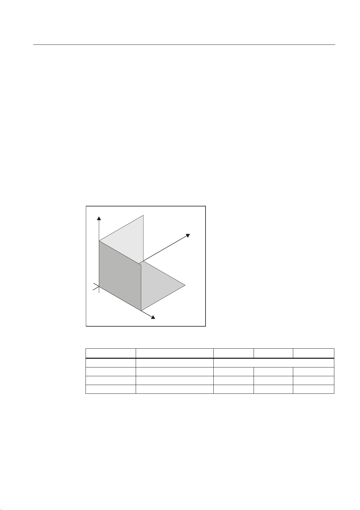
When measuring under milling, machining planes G17, G18 or G19 can be selected.
When measuring under turning, machining plane G18 must be selected.
For tool measurement, the following tool types are permitted:
● Milling, type 1..
● Drill, type 2 ...
● Turning tools, type 5 ...
Depending on the tool type, the tool lengths are assigned to the axes as follows:
● Workpiece probe, milling: Probe types 710, 712, 713, 714
● Workpiece probe, turning: Probe type, 580
Milling
=
*
<
*
*
;
Acts in ... G17 plane G18 plane G19 plane
Tool type: 1xy / 2xy / 710
Length 1 1. Axis of the plane: Z Y X
Length 2 2. Axis of the plane: Y X Z
Length 3 3. Axis of the plane: X Z Y
Lengths 2 and 3 are used in special cases, for example, if an angle head is attached.
Measuring cycles
Programming Manual, 02/2011, 6FC5398-4BP40-0BA0
15
Page 16
Description
1.5 Definition of the planes, tool types
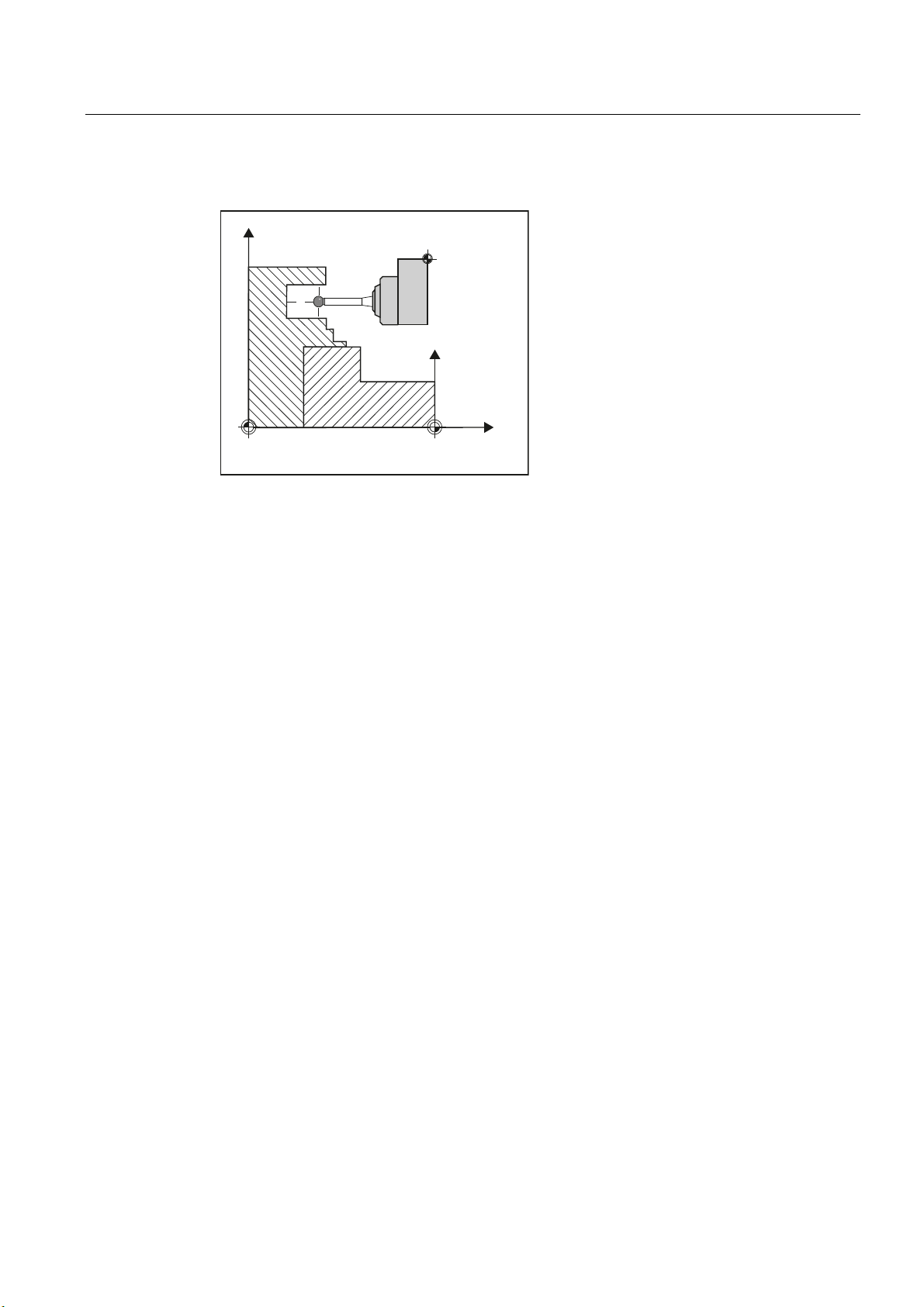
Example of plane definition for milling
)
=
Turning
<
/
:
;
Figure 1-1 Example: Milling machine with G17
<
;
*
=
Turning machines generally only use axes Z and X and therefore:
G18 plane
Tool type 5xy (turning tool, workpiece probe)
Length 1 Acts in X (2nd axis of the plane)
Length 2 Acts in Z (1st axis of the plane)
Measuring cycles
16 Programming Manual, 02/2011, 6FC5398-4BP40-0BA0
Page 17
Description
1.5 Definition of the planes, tool types
G17 and G19 are used for milling on a turning machine. If there is no machine axis Y, milling
can be implemented with the following kinematic transformations.
● TRANSMIT
● TRACYL
In principle, measuring cycles support kinematic transformations. This is stated more clearly
in the individual cycles, measuring variants. Information about kinematic transformation can
be found in the Programming Manual
SINUMERIK 840D sl / 828D Fundamentals
or in the
documentation of the machine manufacturer.
Note
If a drill or milling cutter is measured on a lathe, in most cases, the channel-specific SD
42950 $SC_TOOL_LENGTH_TYPE = 2 is set: These tools are then length-compensated like
a turning tool.
SINUMERIK controls have other machine and setting data that can influence calculation of a
tool.
References:
● /FB1/, Function Manual
● /FB2/, Function Manual
● /FB3/, Function Manual
Example of plane definition for turning
;
Figure 1-2 Example: Lathe with G18
Basic Functions
Expanded Functions
Special Functions
/
)
/
=
Measuring cycles
Programming Manual, 02/2011, 6FC5398-4BP40-0BA0
17
Page 18
Description
1.6 Probes that can be used
1.6 Probes that can be used
General information
To measure tool and workpiece dimensions, an electronic touch-trigger probe is required
that provides a signal change (edge) when deflected with the required repeat accuracy.
The probe must operate virtually bounce-free.
Different types of probe are offered by different manufacturers.
Note
Please observe the information provided by the manufacturers of electronic probes and/or
the machine manufacturer's instructions on the following points:
Electrical connection
Mechanical calibration of the probe
If a workpiece probe is used, both the direction of deflection and transmission of
switching signal to the machine column (radio, infrared light or cable) must be taken into
account. In some versions, transmission is only possible in particular spindle positions or
in particular ranges. This can restrict the use of the probe.
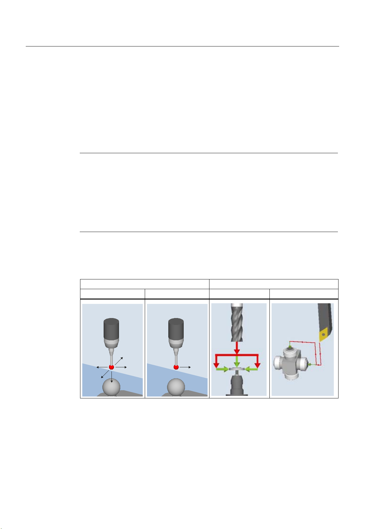
Probes are distinguished according to the number of measuring directions.
● Multi-directional (multi probe)
● Mono directional (mono probe)
Workpiece probe Tool probe
Multi-directional (3D) Monodirectional Milling machines Lathes
<
; ;
<
=
The probes also differ in the form of the stylus tip:
the measuring cycles support pin, L and star probes as autonomous tool types. The use of
the probe types is referenced in the individual measuring cycles. The multi probe is
universally applicable.
The use of probes requires a spindle that can be positioned. For a mono probe, the
switching direction is tracked for each measurement by turning the spindle. This can lead to
a longer program runtime.
Measuring cycles
18 Programming Manual, 02/2011, 6FC5398-4BP40-0BA0
Page 19

Description
1.6 Probes that can be used
Workpiece probe types
The following probe types are provided in the tool management for measuring with
workpiece probes:
Figure 1-3 Probe types in the tool management
There is a calibration tool to calibrate tool probes (type 725) = cylindrical pin
Tool data from probes
The probes differ as a result of the tool type and the switching directions in tool parameter
$TC_DP25[ ] bit16 to bit 25. The switching directions are permanently coded when creating
the tool.
In the application, the probe can encompass several of the following tool types. In this case,
several cutting edges should be created for the probe (D1, D2, etc. ).
Example: Multi probe with a boom
D1 3D_PROBE Type 710
D2 L_PROBE Type 713
The user must take into account the geometry of the probe when pre-positioning. To do this,
you can read out individual tool data in the user program:
Example:
IF (($P_TOOLNO>0) AND ($P_TOOL>0))
R1= ($P_AD[6] ;Read tool radius of the actual tool
ENDIF
The probe is aligned in the + X direction using parameter offset angle.
Measuring cycles
Programming Manual, 02/2011, 6FC5398-4BP40-0BA0
19
Page 20
Description
1.6 Probes that can be used
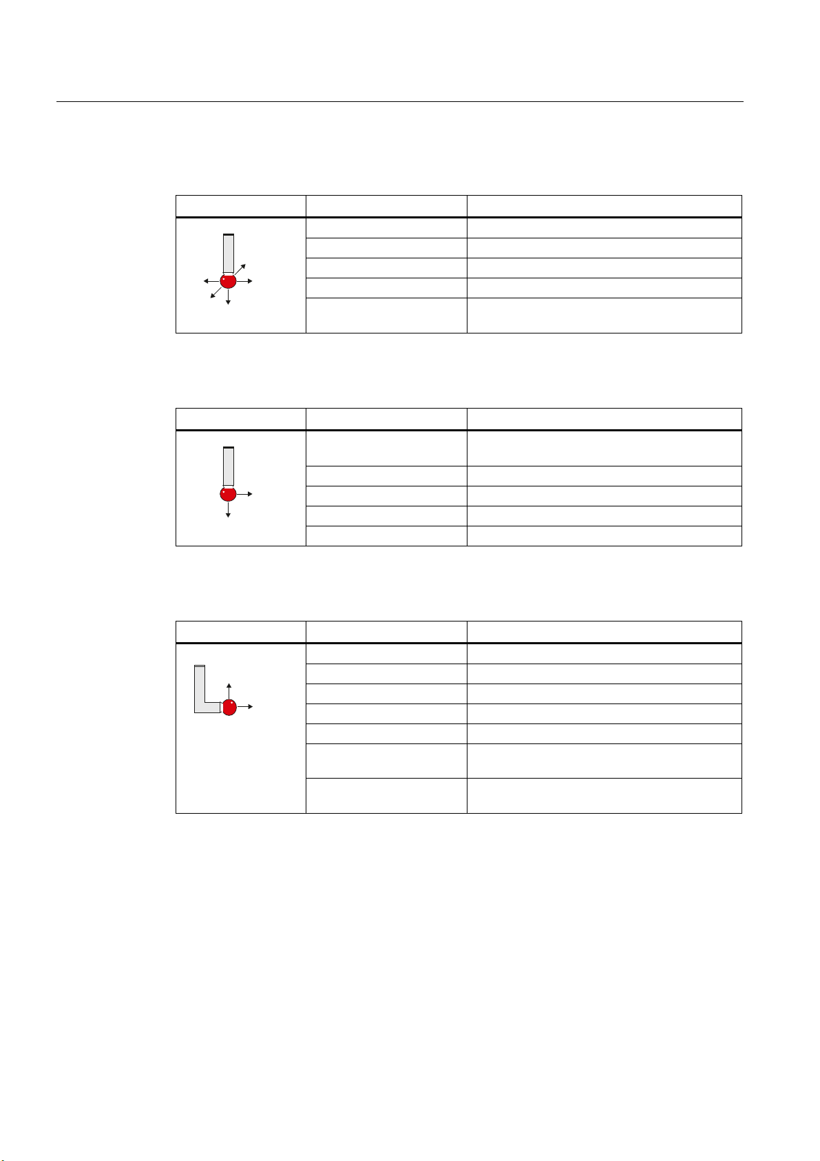
3D_PROBE (multi probe)
Representation Properties Feature
Application: Universal
Type: $TC_DP1[ ]=710
<
;
<
;
=
Tool length: in Z (for G17)
Offset angle: $TC_DP10[ ] = 0
Switching directions: $TC_DP25[ ] = hex 0x00000000
MONO PROBE
Representation Properties Feature
Application: Alignment of the switching direction when
measuring
Type: $TC_DP1[ ]=712
;
=
Tool length: in Z (for G17)
Offset angle: $TC_DP10[ ] = 0 to 359.9 degrees
Switching directions: $TC_DP25[ ] = hex 0x00120000
L_PROBE
Representation Properties Feature
Application: Towing measurement in +Z
=
Type: $TC_DP1[]=713
Tool length: in Z (for G17)
;
Offset angle: $TC_DP10[ ] = 0 to 359.9 degrees
Switching directions: $TC_DP25[ ] = hex 0x00220000
Radius in the plane
$TC_DP6[ ]
(length of the boom):
Radius of the probe ball in
$TC_DP7[ ]
the tool direction:
The tool length is the reference point of the tool holder with the equator of the probe ball.
Measuring cycles
20 Programming Manual, 02/2011, 6FC5398-4BP40-0BA0
Page 21
Description
1.6 Probes that can be used
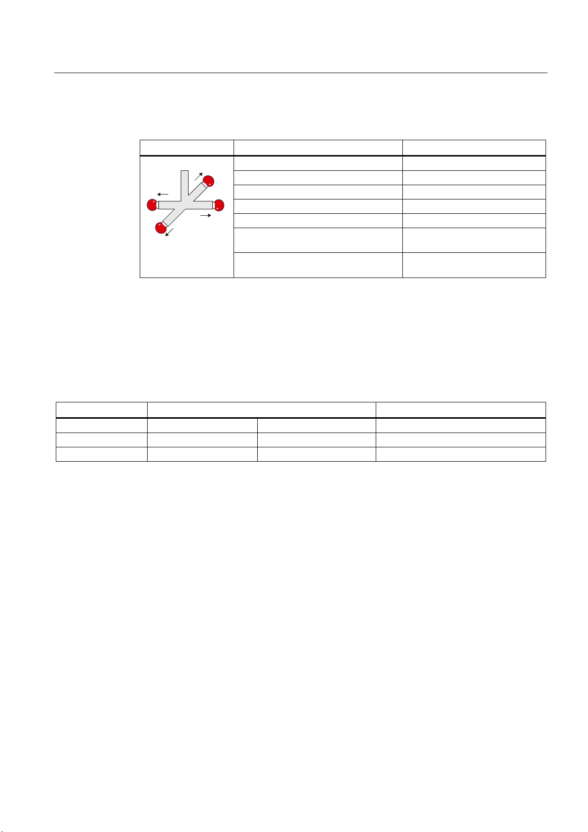
STAR PROBE
Representation Properties Feature
<
Application: Measure hole parallel to the axis
Type: $TC_DP1[ ]=714
;
Tool length: in Z (for G17)
Offset angle: $TC_DP10[ ] = 0 to 359.9 degrees
;
Switching directions: $TC_DP25[ ] = hex 0x000F0000
<
Radius in the plane
(diameter of the star parallel to the axis):
Radius of the probe ball in the tool
$TC_DP6[ ]
$TC_DP7[ ]
direction:
1)
The applications only refer to measurements in the plane (for G17 XY). Measurement in the tool
direction is not permitted using a star probe. If a measurement is to be made in the tool direction, a
star element (boom) must be declared as an L probe.
The tool length is the reference point of the tool holder with the equator of one of the probe
balls.
1)
Assignment of the probe types
Probe type Lathes Milling and machining centers
Tool measurement Workpiece measurement Workpiece measurement
Multidirectional X X X
Monodirectional -- -- X
Measuring cycles
Programming Manual, 02/2011, 6FC5398-4BP40-0BA0
21
Page 22

Description
1.7 Probe, calibration body, calibration tool
1.7 Probe, calibration body, calibration tool
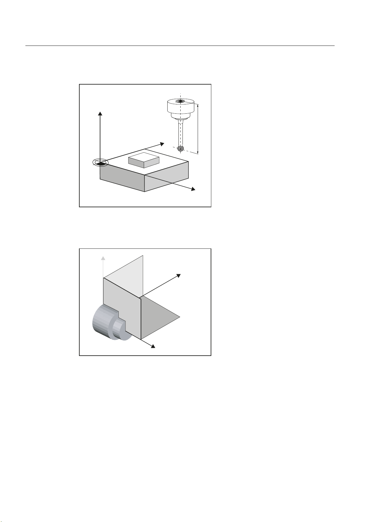
1.7.1 Measuring workpieces on milling machines, machining centers
Probe calibration
All probes must be mechanically correctly adjusted before use. The switching directions
must be calibrated before they are used in the measuring cycles for first-time. This also
applies when changing the stylus tip of the probe.
When being calibrated, the trigger points (switching points), position deviation (skew), and
active ball radius of the workpiece probe are determined and entered into the data fields of
the general setting data SD 54600 $SNS_MEA_WP_BALL_DIAM . There are 12 data fields.
Calibration can be realized in a calibration ring (known bore), on a calibration ball or on
workpiece surfaces, which have an appropriate geometrical precision and low surface
roughness.
Use the same measuring velocity for calibrating and measuring. This applies in particular to
the feedrate overide.
See also
Measuring cycle CYCLE976 with different measuring versions is available to calibrate the
probe.
Calibrate probe - length (CYCLE976) (Page 83)
Calibrate probe - radius in ring (CYCLE976) (Page 86)
Calibrate probe - radius on edge (CYCLE976) (Page 90)
Calibrate probe - calibrate on ball (CYCLE976
) (Page 93)
Measuring cycles
22 Programming Manual, 02/2011, 6FC5398-4BP40-0BA0
Page 23
Description
1.7 Probe, calibration body, calibration tool
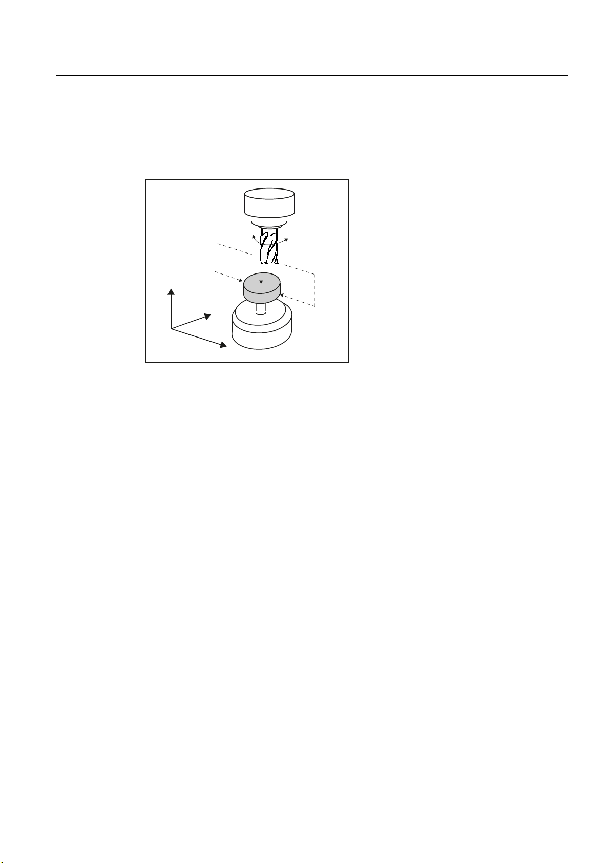
1.7.2 Measuring tools on milling machines, machining centers
Tool probe
=
<
;
Figure 1-4 Measuring a milling cutter
Tool probes have their own data fields in the general setting data:
● For machine-related measurement/calibration:
– SD 54625 $SNS_MEA_TP_TRIG_MINUS_DIR_AX1
– SD 54626 $SNS_MEA_TP_TRIG_PLUS_DIR_AX1
– SD 54627 $SNS_MEA_TP_TRIG_MINUS_DIR_AX2
– SD 54628 $SNS_MEA_TP_TRIG_PLUS_DIR_AX2
● For workpiece-related measurement/calibration:
– SD 54640 $SNS_MEA_TPW_TRIG_MINUS_DIR_AX1
– SD 54641 $SNS_MEA_TPW_TRIG_PLUS_DIR_AX1
– SD 54642 $SNS_MEA_TPW_TRIG_MINUS_DIR_AX2
– SD 54643 $SNS_MEA_TPW_TRIG_PLUS_DIR_AX2
The triggering points (switching points), upper disk diameter and edge length are entered
here.
Approximate values must be entered here before calibration – if cycles are used in automatic
mode. The cycle will then recognize the position of the probe.
The default setting has data fields for three probes. Up to 99 are possible.
Measuring cycles
Programming Manual, 02/2011, 6FC5398-4BP40-0BA0
23
Page 24
Description
1.7 Probe, calibration body, calibration tool
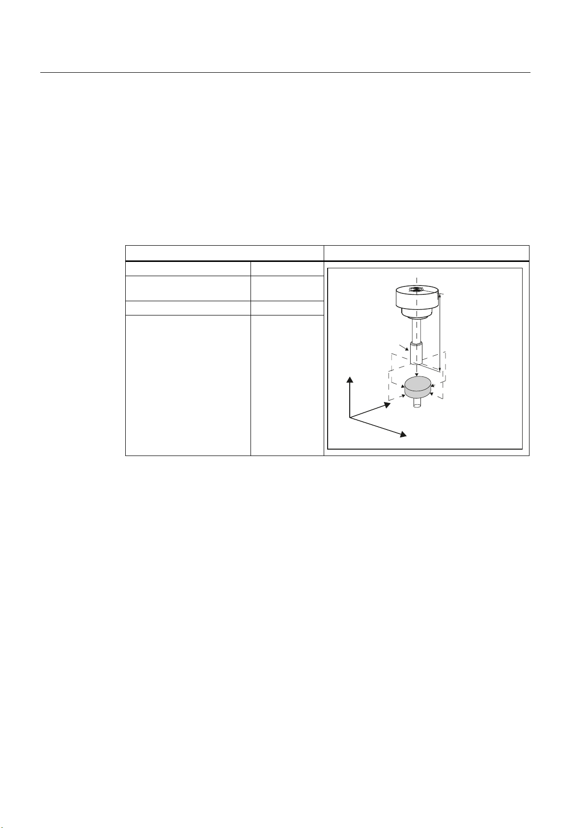
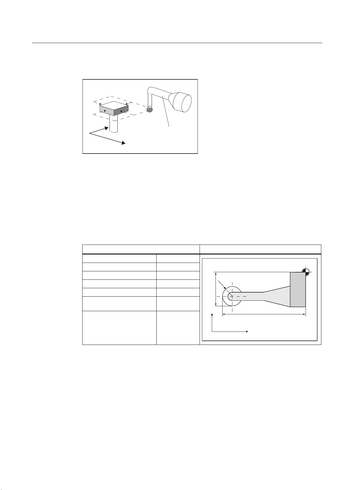
Calibration, calibration tool
A probe must be calibrated before it can be used. Calibration involves precisely determining
the triggering points (switching points) of the tool probe and entering them in special data
fields.
Calibration is performed with a calibration tool. The precise dimensions of the tool are
known.
Use the same measuring velocity for calibrating and measuring.
Measurement version Calibrate probe (CYCLE971) (Page 202) is ready for calibration.
Entry in tool memory Calibrating tool probes
Tool type ($TC_DP1[ ]): 1xy
Length 1 - geometry
($TC_DP3[ ]):
Radius ($TC_DP6[ ]): r
Length 1 - basic dimension
($TC_DP21[ ]):
L1
only if required
&DOLEUDWLRQWRRO
U
)
/
=
<
;
The wear and other tool parameters must be assigned the value 0.
7RROSUREH
Measuring cycles
24 Programming Manual, 02/2011, 6FC5398-4BP40-0BA0
Page 25
Description
1.7 Probe, calibration body, calibration tool
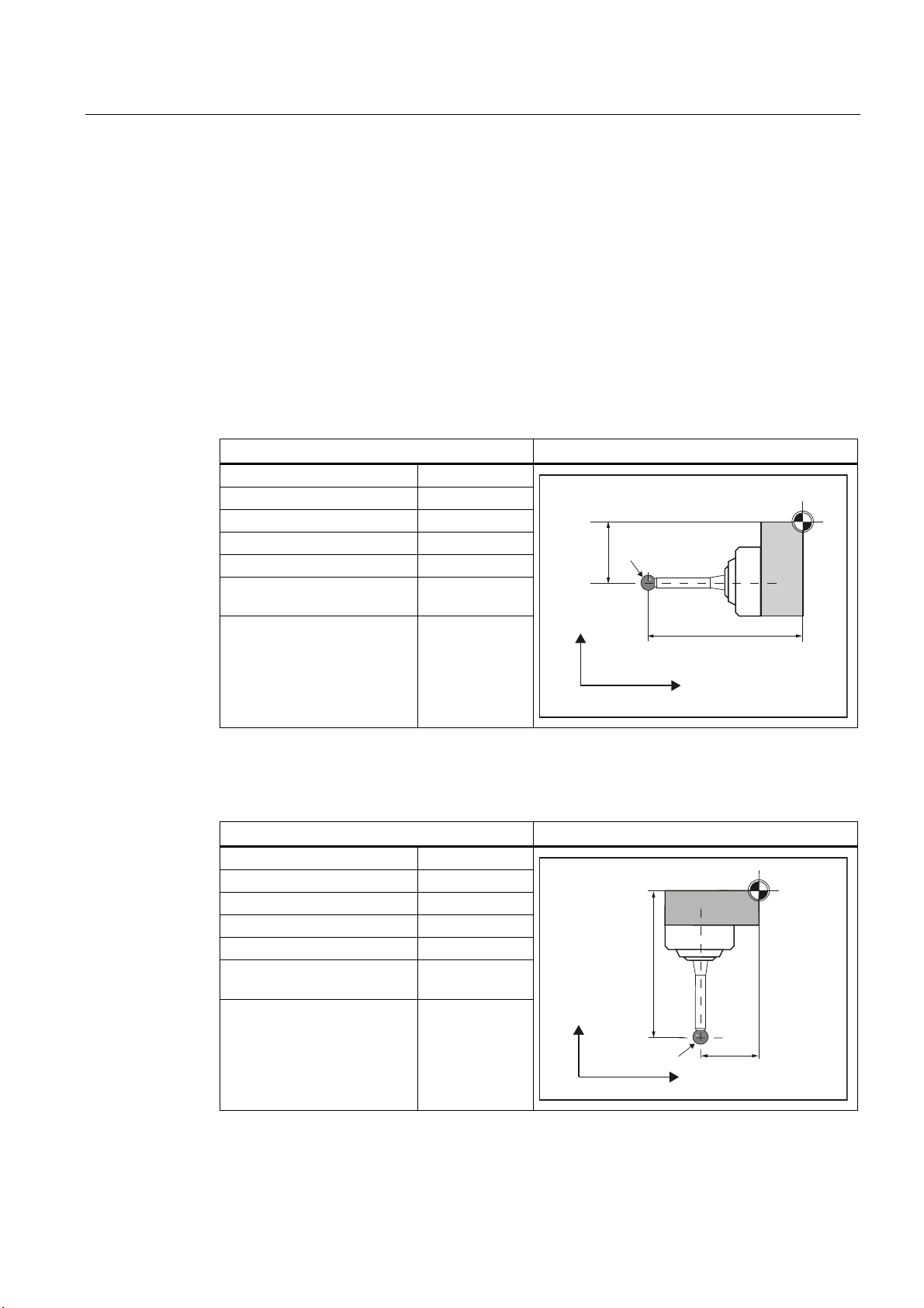
1.7.3 Measuring workpieces at the turning machines
Workpiece probe
On turning machines, the workpiece probes are treated as tool type 5xy with permissible
cutting edge positions (SL) 5 to 8 and must be entered in the tool memory accordingly.
Lengths specified for turning tools always refer to the tool tip, except in the case of
workpiece probes on turning machines where they refer to the probe center.
Probes are classified according to their position:
Workpiece probe SL 7
Entry in tool memory Workpiece probe for a lathe
Tool type ($TC_DP1[ ]): 5xy
Cutting edge ($TC_DP2[ ]): 7
Length 1 - geometry: L1
Length 2 - geometry: L2
Radius ($TC_DP6[ ]): r
Length 1 - basic dimension
($TC_DP21[ ]):
Length 2 - basic dimension
($TC_DP22[ ]):
only if required
only if required
/
U
/
;
)
=
The wear and other tool parameters must be assigned the value 0.
Workpiece probe SL 8
Entry in tool memory Workpiece probe for a lathe
Tool type ($TC_DP1[ ]): 5xy
Cutting edge ($TC_DP2[ ]): 8
Length 1 - geometry: L1
Length 2 - geometry: L2
Radius ($TC_DP6[ ]): r
Length 1 - basic dimension
($TC_DP21[ ]):
Length 2 - basic dimension
($TC_DP22[ ]):
only if required
only if required
;
/
U
=
The wear and other tool parameters must be assigned the value 0.
)
/
Measuring cycles
Programming Manual, 02/2011, 6FC5398-4BP40-0BA0
25
Page 26
Description
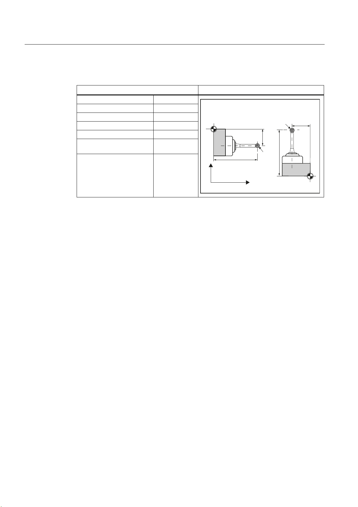
1.7 Probe, calibration body, calibration tool
Workpiece probe SL 5 or SL 6
Entry in tool memory Workpiece probe for a lathe
Tool type ($TC_DP1[ ]): 5xy
Cutting edge ($TC_DP2[ ]): 5 or 6
/
6/
U
/
)
Length 1 - geometry: L1
Length 2 - geometry: L2
Radius ($TC_DP6[ ]): r
Length 1 - basic dimension
only if required
($TC_DP21[ ]):
Length 2 - basic dimension
only if required
($TC_DP22[ ]):
6/
)
/
U
/
;
=
The wear and other tool parameters must be assigned the value 0.
Measuring cycles
26 Programming Manual, 02/2011, 6FC5398-4BP40-0BA0
Page 27
Description
1.7 Probe, calibration body, calibration tool
Calibration, gauging block
;
0
)
;
==
:
Figure 1-5 Calibrating a workpiece probe, example: Calibrating in the reference groove
A probe must be calibrated before it can be used. When being calibrated, the trigger points
(switching points), position deviation (skew), and precise ball radius of the workpiece probe
are determined and entered into the corresponding data fields of the general setting data
SD 54600 $SNS_MEA_WP_BALL_DIAM .
The default setting has data fields for 12 probes.
Calibration of the workpiece probe on turning machines is usually performed with gauging
blocks (reference grooves). The precise dimensions of the reference groove are known and
entered in the associated data fields of the following general setting data:
● SD54615 $SNS_MEA_CAL_EDGE_BASE_AX1
● SD54616 $SNS_MEA_CAL_EDGE_UPPER_AX1
● SD54617 $SNS_MEA_CAL_EDGE_PLUS_DIR_AX1
● SD54618 $SNS_MEA_CAL_EDGE_MINUS_DIR_AX1
● SD54619 $SNS_MEA_CAL_EDGE_BASE_AX2
● SD54620 $SNS_MEA_CAL_EDGE_UPPER_AX2
● SD54621 $SNS_MEA_CAL_EDGE_PLUS_DIR_AX2
● SD54622 $SNS_MEA_CAL_EDGE_MINUS_DIR_AX2
The default setting has data fields for three gauging blocks. In the measuring cycle program,
the selection is made using the number of the gauging block (S_CALNUM).
It is also possible to calibrate on a known surface.
Measuring cycle CYCLE973 with various measuring versions is ready for calibration.
See also
Calibrate probe - length (CYCLE973) (Page 57)
Calibrate probe - radius on surface (CYCLE973) (Page 60)
Calibrate probe - calibrate in groove (CYCLE973) (Page 63)
Measuring cycles
Programming Manual, 02/2011, 6FC5398-4BP40-0BA0
27
Page 28
Description
1.7 Probe, calibration body, calibration tool
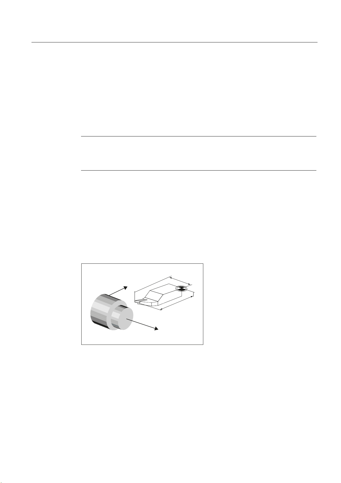
1.7.4 Measuring tools at lathes
Tool probe
0HDVXUHOHQJWK
0HDVXUHOHQJWK
;
=
Figure 1-6 Measuring a turning tool
Tool probes have their own data fields in the general setting data:
● For machine-related measurement/calibration:
– SD 54626 $SNS_MEA_TP_TRIG_PLUS_DIR_AX1
– SD 54625 $SNS_MEA_TP_TRIG_MINUS_DIR_AX1
– SD 54627 $SNS_MEA_TP_TRIG_MINUS_DIR_AX2
– SD 54628 $SNS_MEA_TP_TRIG_PLUS_DIR_AX2
● For workpiece-related measurement/calibration:
– SD 54641 $SNS_MEA_TPW_TRIG_PLUS_DIR_AX1
– SD 54640 $SNS_MEA_TPW_TRIG_MINUS_DIR_AX1
– SD 54642 $SNS_MEA_TPW_TRIG_MINUS_DIR_AX2
– SD 54643 $SNS_MEA_TPW_TRIG_PLUS_DIR_AX2
The triggering points (switching points) are entered here. Approximate values must be
entered here before calibration – if cycles are used in automatic mode. The cycle will then
recognize the position of the probe.
The default setting has data fields for 6 probes.
In addition to turning tools, drills and mills can also be measured.
Measuring cycles
28 Programming Manual, 02/2011, 6FC5398-4BP40-0BA0
Page 29
Description
1.7 Probe, calibration body, calibration tool
Calibration, gauging block
;
=
&DOLEUDWLRQWRRO
A probe must be calibrated before it can be used. Calibration involves precisely determining
the triggering points (switching points) of the tool probe and entering them in special data
fields.
Calibration is performed with a calibration tool. The precise dimensions of the tool are
known.
Measurement version Calibrate probe (CYCLE982) (Page 178) is ready for calibration.
For lathe
s, the calibration tool is treated like a turning tool with cutting edge position 3. The
lengths refer to the ball circumference, not to the ball center.
Entry in tool memory Calibration tool for a tool probe on a lathe
Tool type ($TC_DP1[ ]): 5xy
Cutting edge ($TC_DP2[ ]): 3
Length 1 - geometry: L1
Length 2 - geometry: L2
Radius ($TC_DP6[ ]): r
Length 1 - basic dimension
($TC_DP21[ ]):
Length 2 - basic dimension
($TC_DP22[ ]):
only if required
only if required
U
/
;
/
)
The wear and other tool parameters must be assigned the value 0.
Measuring cycles
Programming Manual, 02/2011, 6FC5398-4BP40-0BA0
=
29
Page 30
Description
1.8 Measurement principle
1.8 Measurement principle
Flying measurement
1&
0HDVXULQJF\FOH
The principle of "flying measurement" is implemented in the SINUMERIK control. The probe
signal is processed directly on the NC so that the delay when acquiring measured values is
minimal. This permits a higher measuring speed for the prescribed measuring precision and
time needed for measuring is reduced.
Connecting probes
Two inputs for connecting touch trigger probes are provided on the I/O device interface of
the SINUMERIK control systems.
'HOHWH
GLVWDQFHWR
JR
$FWXDOYDOXHDFTXLVLWLRQ
3RVLWLRQFRQWURO
$FWXDO
YDOXH
Machine manufacturer
Please observe the machine manufacturer’s instructions.
Measuring cycles
30 Programming Manual, 02/2011, 6FC5398-4BP40-0BA0
Page 31

Description
1.8 Measurement principle
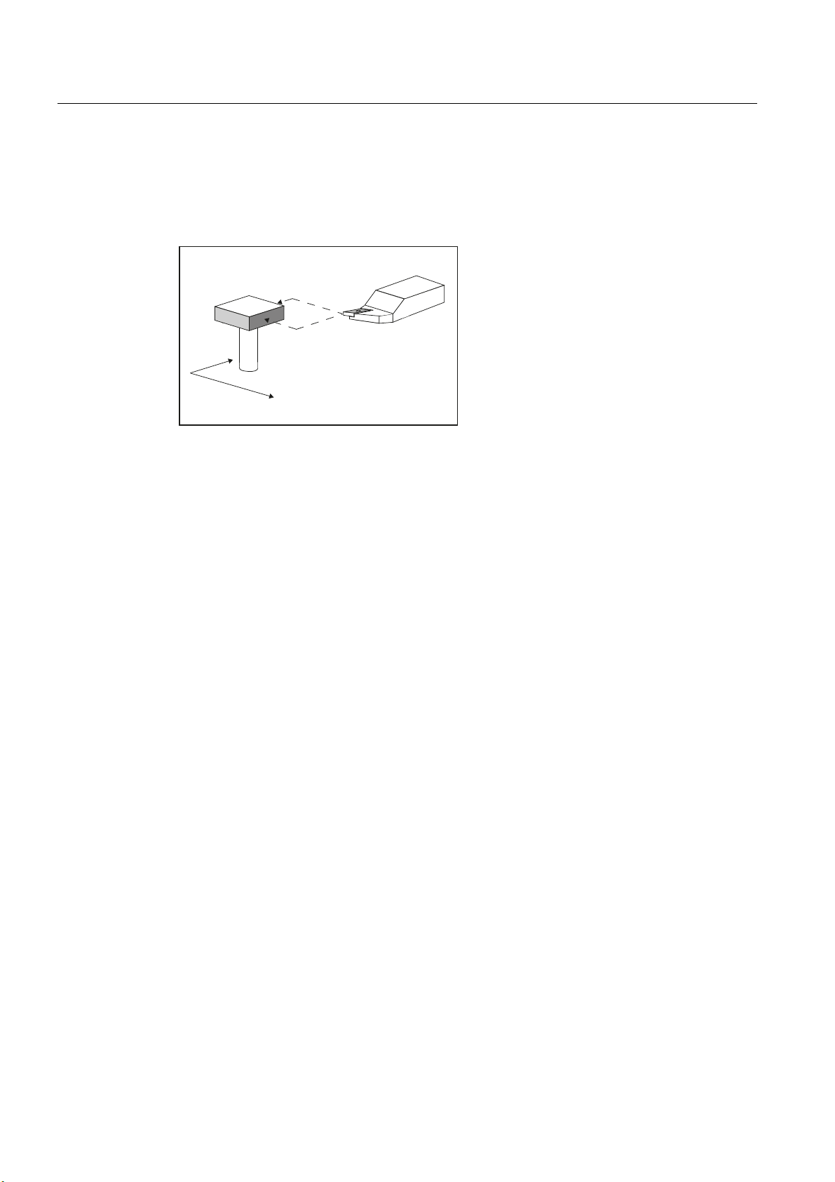
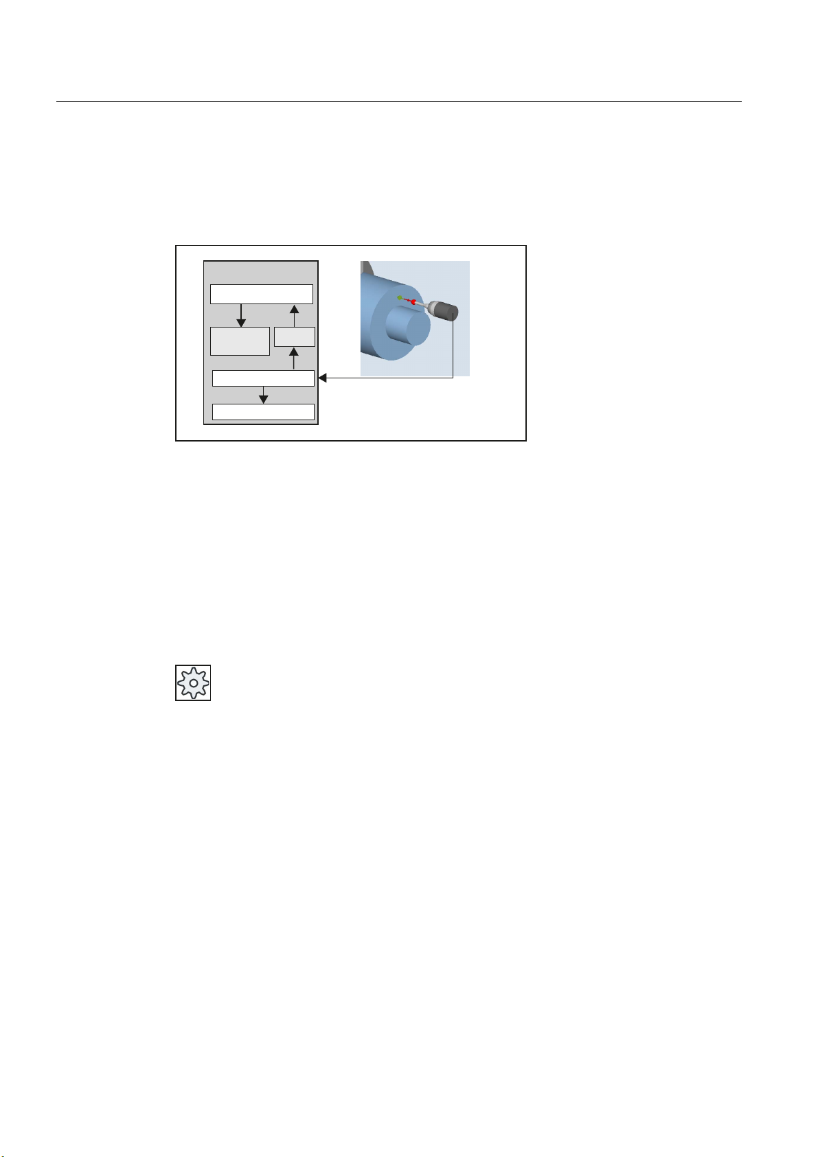
Measurement operation sequence using the example set edge (CYCLE978)
Figure 1-7 Measurement operation sequence, example set edge (CYCLE978)
The sequence is described using the measuring version, set edge (CYCLE978). The
sequence is essentially the same for the other measuring cycles.
The starting position for the measuring procedure is the position DFA in front of the specified
set position (expected contour).
Figure 1-8 Starting position
The starting position is calculated in the cycle based on parameter entries and probe data.
The traversing distance from the pre-position, defined by the user program, to the starting
position of the measuring distance is either traversed with rapid traverse G0 or with
positioning speed G1 (depending on the parameter). From the starting position, the
measuring velocity is effective, which is saved in the calibration data.
The switching signal is expected along path 2 · DFA as from the starting position. Otherwise,
an alarm will be triggered or the measurement repeated.
The resulting maximum measuring position is available in the result parameters _OVR[ ] and
_OVI[ ] of the measuring cycle.
Measuring cycles
Programming Manual, 02/2011, 6FC5398-4BP40-0BA0
31
Page 32

Description
1.8 Measurement principle
At the instant the switching signal is output by the probe, the current actual position is stored
internally "on-the-fly" as the actual value, the measuring axis is stopped and then the "Delete
distance-to-go" function is executed.
The distance-to-go is the path not yet covered in the measuring block. After deletion, the
next block in the cycle can be processed. The measuring axis travels back to the starting
position. Any measurement repetitions selected are restarted from this point.
Measurement path DFA
Measurement path DFA defines the distance between the starting position and the expected
switching position (setpoint) of the probe.
Measuring velocity
As measuring feedrate, all of the measuring cycles use the value saved in the general
setting data SD54611 after the calibration of the workpiece probe. A different measuring
feedrate can be assigned for each calibration field [n].
To calibrate the measuring probe, either the measuring feedrate from the channel-specific
setting data SD55630 $SCS_MEA_FEED_MEASURE is used (default value: 300 mm/min) or
the measuring feedrate can be overridden in the input screen form at the calibration instant.
To do this, bit 4 must be set to 1 in the general setting data SD54760
$SNS_MEA_FUNCTION_MASK_PIECE.
The maximum permissible measuring velocity is derived from:
● The deceleration behavior of the axis.
● The permissible deflection of the probe.
● The signal processing delay.
Deceleration distance, deflection of probe
CAUTION
Safe deceleration of the measuring axis to standstill within the permissible deflection path
of the probe must always be ensured.
Otherwise damage will occur!
A delay t, typical for the control, is taken into account in signal processing (IPO cycle) for the
time between detection of the switching signal and output of the deceleration command to
the measuring axis: general machine data MD10050 $MN_SYSCLOCK_CYCLE_TIME and
MD10070 $MN_IPO_SYSCLOCK_TIME_RATIO). This gives the braking distance
component.
The following error of the measuring axis is reduced. The following error is velocity
dependent and at the same time dependent on the control factor of the measuring axis
(servo gain of the associated machine axis: servo gain factor).
The deceleration rate of the axis must also be taken into account.
Measuring cycles
32 Programming Manual, 02/2011, 6FC5398-4BP40-0BA0
Page 33

Description
1.8 Measurement principle
Together they produce an axis-specific velocity-dependent deceleration distance.
The Kv factor is the axis MD 32200 $MA_POSCTRL_GAIN.
The maximum axis acceleration / deceleration rate a is saved in axis MD 32300
$MA_MAX_AX_ACCEL . It may have a lesser effect due to other influences.
Always use the lowest values of the axes involved in the measurement.
Measuring accuracy
A delay occurs between detection of the switching signal from the probe and transfer of the
measured value to the control. This is caused by signal transmission from the probe and the
hardware of the control. In this time a path is traversed that falsifies the measured value.
This influence can be minimized by reducing the measuring speed.
The rotation when measuring a milling tool on a rotating spindle has an additional influence.
This can be compensated using compensation tables.
The measurement accuracy that can be obtained is dependent on the following factors:
● Repeat accuracy of the machine
● Repeat accuracy of the probe
● Resolution of the measuring system
NOTICE
Precise measurement is only possible with a probe calibrated under the measurement
conditions, i.e. working plane, orientation of the spindle in the plane and measuring velocity
are the same for both measurement and calibration. Deviations result in measurement
errors.
Calculation of the deceleration distance
V>PP@
˂V
Y PPLQ
Y PPLQ
=HURVSHHGRIWKH
D[LV
6WDQGVWLOO
˂V
Y PPLQ
PVGHOD\VLJQDOSURFHVVLQJ
6WDQGVWLOO
Figure 1-9 Distance-time diagram at different measuring velocities according to the calculation
example
Measuring cycles
Programming Manual, 02/2011, 6FC5398-4BP40-0BA0
W>PV@
33
Page 34

Description
1.8 Measurement principle
The deceleration path to be considered is calculated as follows:
Y
VE YyW
˂V
D
˂V
˂V
sb Braking distance in mm
v Measuring velocity in m/s
t Delay signal in s
2
a Deceleration in m/s
Δs Following error in mm
Δs = v / Kv v here in m/min
Kv Servo gain in (m/min)/mm
Example of calculation:
● v = 6 m/min = 0.1 m/s measuring velocity
● a = 1 m/s
2
deceleration
● t = 16 ms signal delay
● Kv = 1 in (m/min)/mm
Intermediate steps:
Δs = v / Kv = 6[m/min] / 1[(m/min)/mm] = 6 mm Following error
= v²/2a = 0,1 [m/s]² / 2 · 1 [m/s²] = 5 mm Axis-specific component
Δs
2
= v · t = 0,1 [m/s] · 0,016 [s] = 1,6 mm Percentage due to signal delay
Δs
1
Overall result:
= Δs1 + Δs2 + Δs = 6 mm + 5 mm + 1,6 mm = 12,6 mm Braking distance
s
b
The deflection of the probe = braking distance to zero speed of the axis is 12.6 mm.
Measuring cycles
34 Programming Manual, 02/2011, 6FC5398-4BP40-0BA0
Page 35

Description
1.9 Measuring strategy for measuring workpieces with tool offset
1.9 Measuring strategy for measuring workpieces with tool offset
The actual workpiece dimensions must be measured exactly and compared with the setpoint
values to be able to determine and compensate the actual dimensional deviations on the
workpiece. An offset value can then be ascertained for the tool used for machining.
Function
When taking measurements on the machine, the actual dimensions are derived from the
path measuring systems of the position-controlled feed axes. For each dimensional deviation
determined from the set and actual workpiece dimensions there are many causes which
essentially fall into three categories:
● Dimensional deviations with causes that are n o t subject to a particular trend, e.g.
positioning scatter of the feed axes or differences in measurement between the internal
measurement (probe) and the external measuring device (micrometer, measuring
machine, etc.).
In this case, it is possible to apply empirical values, which are stored in separate
memories. The set/actual difference determined is automatically compensated by the
empirical value.
● Dimensional deviations with causes that a r e subject to a particular trend, e.g. tool wear
or thermal expansion of the leadscrew.
● Accidental dimensional deviations, e.g. due to temperature fluctuations, coolant or slightly
soiled measuring points.
Assuming the ideal case, only those dimensional deviations that are subject to a trend
can be taken into account for compensation value calculation. Since, however, it is hardly
ever known to what extent and in which direction accidental dimensional deviations
influence the measurement result, a strategy (sliding averaging) is needed that derives a
compensation value from the actual/set difference measured.
Mean value calculation
Mean value calculation in conjunction with measurement weighting has proven a suitable
method.
When correcting a tool, it can be selected whether a correction is made based on the actual
measurement, or whether an average value of the measurement differences should be
generated over several measurements which is then used to make the correction.
The formula of the mean value generation chosen is:
-
DMi
-=
MiMi
altneu
Mv
Mean value new = amount of compensation
new
Mean value prior to last measurement
Mv
old
ialt
k
k Weighting factor for mean value calculation
Actual/set difference measured (minus any empirical value)
D
i
Measuring cycles
Programming Manual, 02/2011, 6FC5398-4BP40-0BA0
35
Page 36

Description
1.9 Measuring strategy for measuring workpieces with tool offset
The mean value calculation takes account of the trend of the dimensional deviations of a
machining series. The weighting factor k from which the mean value is derived is selectable.
A new measurement result affected by accidental dimensional deviations only influences the
new tool offset to some extent, depending on the weighting factor.
Computational characteristic of the mean value with different weightings k
0LWWHOZHUW
:RUNRIIVHW
6B7=/
&DOFXODWHG
PHDQYDOXHV
6HWSRLQW
N
1XPEHURIDYHUDJLQJV
QXPEHURIZRUNSLHFHV
N
N
&DOFXODWHG
PHDQYDOXH
N
/RZHUOLPLW
ZRUNRIIVHW
L
Figure 1-10 Mean value generation with influence of weighting k
● The greater the value of k, the slower the formula will respond when major deviations
occur in computation or counter compensation. At the same time, however, accidental
scatter will be reduced as k increases.
● The lower the value of k, the faster the formula will react when major deviations occur in
computation or counter compensation. However, the effect of accidental variations will be
that much greater.
● The mean value Mv is calculated starting at 0 over the number of workpieces i, until the
calculated mean value exceeds the work offset range (
S_TZL). From this limit on, the
calculated mean value is applied as an offset.
● Once the mean value has been used for the offset, it is deleted from the memory. The
next measurement then starts again with Mv
Measuring cycles
old
= 0.
36 Programming Manual, 02/2011, 6FC5398-4BP40-0BA0
Page 37

Description
1.9 Measuring strategy for measuring workpieces with tool offset
Table 1- 1 Example of mean value calculation and offset
Lower limit = 40 µm
(S_TZL = 0.04)
i Di
[µm]
Mv
k = 3
[µm]
Mv
k = 2
[µm]
1. measurement 30 10 15
2. Measurement 50 23,3 32,5
3. Measurement 60 35,5
46,2 ③
4. Measurement 20 30,3 10
5. Measurement 40 32,6 25
6. Measurement 50 38,4 37,5
7. Measurement 50
42,3 ① 43,75 ④
8. Measurement 30 10 15
9. Measurement 70 30
10. Measurement 70
43,3 ②
42,5 ⑤
35
Characteristic of the mean value for two different
weighting factors
0HDQYDOXH
0HDQYDOXHV!6B7=/DUHH[HFXWHGDVWKHRIIVHW
1
3
L
N
N
4
5
1XPEHURIDYHUDJLQJVQXPEHU
RIZRUNSLHFHV
:RUNRIIVHW
2
For the measurements with marked fields, tool offset is performed with the mean value
(calculated mean value >S_TZL):
● If k=3 in the 7th and 10th measurement (
● If k=2 in the 3rd, 7th, and 9th measurement (
① and ②),
③, ④ and ⑤).
6B7=/
Measuring cycles
Programming Manual, 02/2011, 6FC5398-4BP40-0BA0
37
Page 38

Description
1.10 Parameters for checking the measurement result and offset
1.10 Parameters for checking the measurement result and offset
For constant deviations not subject to a trend, the dimensional deviation measured can be
compensated by an empirical value in certain measuring variants.
For other compensations resulting from dimensional deviations, symmetrical tolerance bands
are assigned to the set dimension which result in different responses.
Empirical value / mean value EVN (S_EVNUM)
The empirical values are used to suppress dimensional deviations that are not subject to a
trend.
Note
If empirical values are not to be applied, then S_EVNUM = 0 must be set.
The empirical values themselves are saved in channel-specific SD 55623
$SCS_MEA_EMPIRIC_VALUE.
EVN specifies the number of the empirical value memory. The actual/set difference
determined by the measuring cycle is corrected by this value before any further correction
measures are taken.
This is the case:
● For workpiece measurement with automatic tool offset.
● For single-point measurement with automatic WO correction.
● For tool measurement.
The mean value only refers to the workpiece measurement with automatic tool offset.
For an automatic tool offset, the mean value is generated from the measured difference of
the previous and the actual measurement. This functionality has special significance within a
machining series with measurements performed at the same measuring location.
The function does not have to be activated.
The mean values are stored in the channel-specific SD 55625
$SCS_MEA_AVERAGE_VALUE. The number of the mean value memory is transferred in
the measuring cycle using variable S_EVNUM.
Safe area TSA (S_TSA)
The safe area is effective for almost all measuring variants and does not affect the offset
value; it is used for diagnostics.
If this limit is reached then the following can be assumed:
● A probe defect, or
● An incorrect setpoint position, or
● An illegal deviation from the setpoint position can be assumed.
Measuring cycles
38 Programming Manual, 02/2011, 6FC5398-4BP40-0BA0
Page 39

Description
1.10 Parameters for checking the measurement result and offset
Note
AUTOMATIC mode
AUTOMATIC operation is interrupted and the program cannot continue. An alarm text
appears to warn the user.
Dimension difference check DIF (S_TDIF)
DIF is active only for workpiece measurement with automatic tool offset and for tool
measurement.
This limit has no effect on generation of the compensation value either. When it is reached,
the tool is probably worn and needs to be replaced.
Note
An alarm text is displayed to warn the operator and the program can be continued by means
of an NC start.
This tolerance limit is generally used by the PLC for tool management purposes (twin tools,
wear monitoring).
Tolerance of workpiece: Lower limit (S_TLL), upper limit(S_TUL)
Both parameters are active only for tool measurement with automatic tool offset.
When measuring a dimensional deviation ranging between "2/3 tolerance of workpiece" and
"Dimensional difference control", this is regarded 100% as tool offset. The previous average
value is erased.
This enables a fast response to major dimensional deviations.
Note
When the tolerance limit of the workpiece is exceeded, this is indicated to the user
depending on the tolerance position "oversize" or "undersize".
Measuring cycles
Programming Manual, 02/2011, 6FC5398-4BP40-0BA0
39
Page 40

Description
1.10 Parameters for checking the measurement result and offset
2/3 tolerance of workpiece TMV (S_TMV)
TMV is active only for workpiece measurement with automatic tool offset.
Within the range of "Lower limit" and "2/3 workpiece tolerance" the mean value is calculated
according to the formula described in Section "Measuring strategy".
Note
Mv
is compared with the work offset range:
new
If Mv
is greater than this range, compensation is corrected by Mv
new
and the associated
new
mean value memory is cleared.
If Mv
is less than this range, no compensation is carried out. This prevents excessively
new
abrupt compensations.
Weighting factor for mean value generation FW (S_K)
FW is active only for workpiece measurement with automatic tool offset. The weighting factor
can be used to give a different weighting for each measurement.
A new measurement result thus has only a limited effect on the new tool offset as a function
of FW.
Work offset range TZL (S_TZL)
TZL active for
● Workpiece measurement with automatic tool offset
● Tool measurement and calibration for milling tools and tool probes
This tolerance range corresponds to the amount of maximum accidental dimensional
deviations. It has to be determined for each machine.
No tool compensation is made within these limits.
In workpiece measurement with automatic tool offset, however, the mean value of this
measuring point is updated and re-stored with the measured actual/set difference, possibly
compensated by an empirical value.
The tolerance bands (range of permissible dimensional tolerance) and the responses
derived from them are as follows:
Measuring cycles
40 Programming Manual, 02/2011, 6FC5398-4BP40-0BA0
Page 41

Description
1.10 Parameters for checking the measurement result and offset
● For workpiece measurement with automatic tool offset
$ODUP6DIHDUHDYLRODWHG
76$
7',)
7//78/
709
6DIHDUHD
'LPHQVLRQGLIIHUHQFH
FKHFN
:RUNSLHFHWROHUDQFH
ZRUNSLHFHWROHUDQFH
$ODUP3HUPLVVLEOHGLPHQVLRQDOGLIIHUHQFH
H[FHHGHG
&RUUHFWWKHDFWXDOGHYLDWLRQ
$ODUP$OORZDQFHXQGHUVL]H
&RUUHFWWKHDFWXDOGHYLDWLRQ
0HDQYDOXHJHQHUDWLRQ(91):
DQGFRUUHFWPHDQYDOXH
7=/
:RUNRIIVHWORZHUOLPLW
6HWSRLQW
0HDQYDOXHJHQHUDWLRQLV
VDYHG
Note
In measuring cycles, the workpiece setpoint dimension is placed in the middle of the
permitted ± tolerance limit for reasons associated with symmetry.
● For tool measurement
$ODUP6DIHDUHDYLRODWHG
76$
7',)
6DIHDUHD
'LPHQVLRQGLIIHUHQFH
FKHFN
$ODUP3HUPLVVLEOHGLPHQVLRQDOGLIIHUHQFH
H[FHHGHG
7RROPHPRU\LVFRUUHFWHG
7=/
:RUNRIIVHWORZHUOLPLW
Measuring cycles
Programming Manual, 02/2011, 6FC5398-4BP40-0BA0
6HWSRLQW
7RROPHPRU\XQFKDQJHG
41
Page 42

Description
1.10 Parameters for checking the measurement result and offset
● For workpiece measurement with WO correction
$ODUP6DIHDUHDYLRODWHG
76$
6DIHDUHD
&RUUHFWLRQRIWKH:2PHPRU\
6HWSRLQW
● For workpiece probe calibration
$ODUP6DIHDUHDYLRODWHG
76$
6DIHDUHD
7=/
:RUNRIIVHWORZHUOLPLW
● For tool probe calibration
76$
7=/
6DIHDUHD
:RUNRIIVHWORZHUOLPLW
:RUNSLHFHSUREHGDWDDUHFRUUHFWHG
6HWSRLQW
:RUNSLHFHSUREHGDWD
XQFKDQJHG
$ODUP6DIHDUHDYLRODWHG
7RROSUREHGDWDDUHFRUUHFWHG
6HWSRLQW
7RROSUREHGDWDXQFKDQJHG
Measuring cycles
42 Programming Manual, 02/2011, 6FC5398-4BP40-0BA0
Page 43

Description
1.11 Effect of empirical value, mean value, and tolerance parameters
1.11 Effect of empirical value, mean value, and tolerance parameters
The following flowchart shows the effect of empirical value, mean value, and tolerance
parameters on workpiece measurement with automatic tool offset.
0HDVXULQJF\FOH
0HDVXUH
&DOFXODWHDFWXDOVHWSRLQW
GLIIHUHQFH
'LIIHUHQFHPLQXV
HPSLULFDOYDOXH
'LIIHUHQFH!WRO
RIWKHZRUNSLHFH
6B709
&DOFXODWHFRUUHFWLRQYDOXH
WDNLQJLQWRDFFRXQW
ZHLJKWLQJIDFWRU6B.
&RUUHFWLRQYDOXH
1R
!ORZHUOLPLW
6B7=/
<HV
2IIVHWE\FRUUHFWLRQYDOXH
ZHDNHQHGRIIVHW
'HOHWHFRUUHFWLRQ
PHDQYDOXH
1R
2IIVHWE\
GLIIHUHQFH
RIIVHW
'HOHWHFRUUHFWLRQ
PHDQYDOXH
①
<HV
'LIIHUHQFH!WRO
RIWKHZRUNSLHFH
6B709
<HV
2IIVHWE\
GLIIHUHQFH
RIIVHW
'HOHWHFRUUHFWLRQ
PHDQYDOXH
1R
'LIIHUHQFH!7RO
RIWKHZRUNSLHFH
6B78/6B7//
,QWHUQDOSDUDPHWHU
SUHVHQWO\DOZD\V
<HV1R
'LIIHUHQFH!VDIH
1R
'LIIHUHQFH!
'LPHQVLRQDO
GLIIHUHQFHPRQL
WRULQJ6B7',)
<HV
&DOFXODWHPHDQRIIVHWYDOXH
WDNLQJLQWRDFFRXQWZHLJKWLQJ
IDFWRU6B.
1R
6DYHRIIVHW
DYHUDJHYDOXH
DUHD6B76$
<HV
'LVSOD\
$OORZDQFHRUXQGHUVL]H
<HV1R
0HDQRIIVHWYDOXH!
ORZHUOLPLW6B7=/
&RUUHFWLRQE\PHDQ
RIIVHWYDOXH
ZHDNHQHGRIIVHW
'HOHWHFRUUHFWLRQPHDQ
YDOXH
(QG
SD 54740 $SNS_MEA_FUNCTION_MASK, Bit 0
'LVSOD\
SHUPLVVLEOHGLPHQVLR
QDOGLIIHUHQFHH[FHHGHG
<HV1R
1R
2QO\H[LWWKHSURJUDP
'LVSOD\
6DIHDUHDYLRODWHG
5HSHDWPHDVXU
1R
,VVDIHDUHD
H[FHHGHG"
6B76$
<HV
ZLWK5(6(7
<HV
Measuring cycles
Programming Manual, 02/2011, 6FC5398-4BP40-0BA0
43
Page 44

Description
1.12 Measuring cycle help programs
1.12 Measuring cycle help programs
1.12.1 CYCLE116: Calculation of center point and radius of a circle
Function
This cycle calculates from three or four points positioned on one plane the circle they
inscribe with center point and radius.
To allow this cycle to be used as universally as possible, its data is transferred via a
parameter list.
An array of REAL variables of length 13 must be transferred as the parameter.
<
3
Programming
3
5DGLXV
03
3
3
;
Figure 1-11 Calculation of circle data from 4 points
CYCLE116 (_CAL[ ], _MODE)
Measuring cycles
44 Programming Manual, 02/2011, 6FC5398-4BP40-0BA0
Page 45

Description
1.12 Measuring cycle help programs
Transfer parameters
● Input data
Parameters Data type Meaning
_CAL [0]
_CAL [1]
_CAL [2]
_CAL [3]
_CAL [4]
_CAL [5]
_CAL [6]
_CAL [7]
_CAL [8]
● Output data
Parameters Data type Meaning
_CAL [9]
_CAL [10]
_CAL [11]
_CAL [12]
_MODE
REAL Number of points for calculation (3 or 4)
REAL 1. Axis of the plane of the first point
REAL 2. Axis of the plane of the first point
REAL 1. Axis of the plane of the second point
REAL 2. Axis of the plane of the second point
REAL 1. Axis of the plane of the third point
REAL 2. Axis of the plane of the third point
REAL 1. Axis of the plane of the fourth point
REAL 2. Axis of the plane of the fourth point
REAL 1. Axis of the plane of the circle center point
REAL 2. Axis of the plane of the circle center point
REAL Circle radius
REAL Status for the calculation
0 = Calculation in progress
1 = Error occurred
INTEGER Error number (61316 or 61317 possible)
Note
This cycle is called as a subroutine by, for example, measuring cycle CYCLE979.
Example
%_N_Circle_MPF
DEF INT _MODE
DEF REAL _CAL[13]= (3,0,10,-10,0,0,-10,0,0,0,0,0,0) ;3 points specified P1: 0,10
P2: -10,0
P3: 0,-10
CYCLE116(_CAL[ ], _MODE) ;Result: _CAL[9]=0
_CAL[10]=0
_CAL[11]=10
_CAL[12]=0
_ALM=0
M0
STOPRE
M30
Measuring cycles
Programming Manual, 02/2011, 6FC5398-4BP40-0BA0
45
Page 46

Description
1.13 Miscellaneous functions
1.12.2 CUST_MEACYC: User program before/after measurements are performed
Function
The CUST_MEACYC cycle is called at the beginning of each measuring cycle.
It can be used by users to program sequences necessary before starting a measurement
(e.g. to activate probe).
In the as-delivered state, this cycle only contains one CASE statement that executes a jump
to a label with subsequent M17 (end of subroutine) for each measuring cycle.
Example
_M977: ;before measurement in CYCLE977
M17 ;end of cycle
From this label all actions to be executed on each CYCLE977 call must be programmed.
References
Commissioning manual
SINUMERIK 840D sl Basesoftware and Operating Software
1.13 Miscellaneous functions
1.13.1 Measuring cycle support in the program editor
The program editor offers extended measuring cycle support for inserting measuring cycle
calls into the program.
Prerequisite
Hardware TCU or PCU.
Function
This measuring cycle support provides the following functionality:
● Measuring cycle selection via softkeys
.
● Input screen forms for parameter assignment with help displays
● Retranslatable program code is generated from the individual screen forms.
Measuring cycles
46 Programming Manual, 02/2011, 6FC5398-4BP40-0BA0
Page 47

Description
1.13 Miscellaneous functions
1.13.2 Measuring result screens
Function
Measurement result displays can be shown automatically during a measuring cycle. In the
channel-specific SD 55613 $SCS_MEA_RESULT_DISPLAY, you can select between the
following measurement result screens:
= 0 The measurement results screen is not displayed (default setting)
= 1 The measurement results screen is displayed for 8 seconds.
= 3 The measuring cycle stops at the NC command "M0", the measuring results screen is
statically displayed.
The measuring cycle is continued with NC Start, the measuring results screen is
deselected.
= 4 The measuring results screen is only displayed for cycle alarms 61303, 61304, 61305
and 61306.
The measuring cycle is continued with NC Start, the measuring results screen is
deselected.
The measuring cycles can display different measuring result screens depending on the
measuring variant:
● Calibrating tool probes
● Tool measurement
● Calibrating workpiece probes
● Workpiece measurement
Displaying measuring results screens
The measuring results screens contain the following data:
Calibrating tool probes
● Measuring cycle and measuring version
● Trigger values of axis directions and differences
● Probe number
● Safe area
Tool measurement
● Measuring cycle and measuring version
● Actual values and differences for tool offsets
● Safe area and permissible dimensional difference
● T name, D number
Measuring cycles
Programming Manual, 02/2011, 6FC5398-4BP40-0BA0
47
Page 48

Description
1.13 Miscellaneous functions
Calibrating workpiece probes
● Measuring cycle and measuring version
● Trigger values of axis directions and differences
● Position deviation (probe skew) when calibrating in the plane
● Probe number
● Safe area
Workpiece measurement
● Measuring cycle and measuring version
● Setpoints, actual values and their differences
● Tolerance upper and lower limits (for tool offset)
● Offset value
● Probe number
● Safe area and permissible dimensional difference
● T name, D number and DL number or WO memory number for automatic offset
Example of measurement result display
Measuring cycles
48 Programming Manual, 02/2011, 6FC5398-4BP40-0BA0
Page 49

Measuring variants
2.1 General requirements
2.1.1 Overview of the measuring cycles
Function of the measuring cycles
The following table describes all the measuring cycle functions for the turning and milling
technologies.
Table 2- 1 Measuring cycles
Measuring
cycle
CYCLE973 2) This measuring cycle can be used to calibrate a workpiece
CYCLE974 2) This measuring cycle can be used to determine the
CYCLE994 2) This measuring cycle can be used to determine the
CYCLE976 Using this measuring cycle, a workpiece probe can be
CYCLE961 This measuring cycle can be used to determine the
CYCLE977 This measuring cycle can be used to determine the center
Description Measuring versions
probe on a surface on the workpiece or in a groove.
workpiece zero in the selected measuring axis or a tool
offset with 1-point measurement.
workpiece zero in the selected measuring axis with 2-point
measurement. To do this, two opposite measuring points
on the diameter are approached automatically in
succession
calibrated in a calibration ring or on a calibration ball
completely in the working plane or at an edge for a
particular axis and direction.
position of a workpiece corner (inner or outer) and use this
as work offset.
point in the plane as well as the width or the diameter.
2
Calibrate probe - length
Calibrate probe - radius on surface
Calibrate probe - probe in groove
Turning measurement - front edge
Turning measurement - inside diameter
Turning measurement - outside diameter
Turning measurement - inside diameter
Turning measurement - outside diameter
Calibrate probe - length on surface
Calibrate probe - radius in ring
Calibrate probe - radius on edge
Calibrate probe - calibration on sphere
Corner - right-angled corner
Corner - any corner
Edge distance - groove
Edge distance - rib
Hole - rectangular pocket
Hole - 1 hole
Spigot - rectangular spigot
Spigot - 1 circular spigot
Measuring cycles
Programming Manual, 02/2011, 6FC5398-4BP40-0BA0
49
Page 50

Measuring variants
2.1 General requirements
Measuring
cycle
CYCLE978 This measuring cycle can be used to measure the position
CYCLE979 This measuring cycle can be used to measure the center
CYCLE996 This measuring cycle can be used to determine
CYCLE997 This measuring cycle can be used to determine the center
CYCLE998 This measuring cycle can be used to determine the
CYCLE971 1) This measuring cycle can be used to calibrate a tool probe
CYCLE982 2) This measuring cycle can be used to calibrate a tool probe
Description Measuring versions
of an edge in the workpiece coordinate system.
point in the plane and the radius of circle segments.
transformation-relevant data for kinematic transformations
with contained rotary axes.
point and diameter of a ball. Furthermore, the center
points of three distributed balls can be measured. The
plane formed through the three ball center points,
regarding its angular position, is determined referred to the
working plane in the workpiece coordinate system.
angular position of a surface (plane) referred to the
working plane and the angle of edges in the workpiece
coordinate system.
and measure the tool length and/or tool radius for milling
tools.
and measure turning, drilling and milling tools on turning
machines.
Edge distance - set edge
Hole - inner circle segment
Spigot - outer circle segment
3D - kinematics
3D - sphere
3D - 3 spheres
Edge distance - align edge
3D - align plane
Calibrate probe
Measure tool
Calibrate probe
Turning tool
Milling tool
Drill
1) Only for milling technology
2) Only for turning technology
Measuring cycles
50 Programming Manual, 02/2011, 6FC5398-4BP40-0BA0
Page 51

Measuring variants
2.1 General requirements
2.1.2 Selection of the measuring variants via softkeys (turning)
The following shows the measuring variants of the turning technology as a menu tree.
Preconditions
All of the measuring variants available in the control are shown in the display. However, on a
specific system, only those steps can be selected that are possible for the set extended
technology.
1)
The "Inside diameter" softkey is displayed if bit1 =1 is set in the general SD 54764
$SNS_MEA_FUNCTION_MASK_TURN.
2)
The "3D" softkey is displayed if bit 1 = 1 is set in the general SD 54760
$SNS_MEA_FUNCTION_MASK_PIECE.
3)
The "kinematics" softkey is only displayed in the G code program, if the "Measure
kinematics" option is set.
4)
These softkeys are displayed if the "Milling" extended technology is set (channel-specific
MD 52201 $MCS_TECHNOLOGY_EXTENSION = 2).
Turning technology menu tree
→
→
4)
Length (CYCLE973)
(Page 57)
Radius in ring (CYCLE976)
(Page 86)
Radius on surface (CYCLE973)
(Page 60)
4)
Calibrate on ball (CYCLE976)
(Page 93)
Calibrate in groove (CYCLE973)
(Page 63)
→
1)
Front edge (CYCLE974)
(Page 67)
Inside diameter (CYCLE974,
CYCLE
Outer diameter (CYCLE974,
CYCLE
4)
→
Set edge (CYCLE978)
(Page 96)
Align edge (CYCLE998)
(Page 100)
Groove (CYCLE977)
(Page 106)
Rib (CYCLE977)
(Page 110)
994) (Page 71)
994) (Page 76)
Measuring cycles
Programming Manual, 02/2011, 6FC5398-4BP40-0BA0
51
Page 52

Measuring variants
2.1 General requirements
4)
→
4)
→
4)
→
2), 4)
→
→
3)
Calibrate probe (CYCLE982)
Turning tool (CYCLE982)
4)
Milling tool (CYCLE982)
Drill (CYCLE982)
Right-angled corner (CYCLE961)
(Page 114)
Any corner (CYCLE961)
(Page 118)
Rectangular pocket (CYCLE977)
(Page 122)
1 hole (CYCLE977)
(Page 126)
Inner circle segment (CYCLE979)
(Page 130)
Rectangular spigot (CYCLE977)
(Page 134)
1 circular spigot (CYCLE977)
(Page 138)
Outer circle segment (CYCLE979)
(Page 142)
Align plane (CYCLE998)
(Page 146)
Sphere (CYCLE997)
(Page 150)
3 spheres (CYCLE997)
(Page 154)
Kinematics (CYCLE996)
(Page 159)
(Page 178)
(Page 182)
(Page 186)
(Page 193)
Measuring cycles
52 Programming Manual, 02/2011, 6FC5398-4BP40-0BA0
Page 53

Measuring variants
2.1 General requirements
2.1.3 Selection of the measuring variants via softkeys (milling)
The following shows the measuring variants for the milling technology as a menu tree.
Preconditions
All of the measuring variants available in the control are shown in the display. However, on a
specific system, only those steps can be selected that are possible for the set extended
technology.
1)
The "Inside diameter" softkey is displayed if bit1 =1 is set in the general SD 54764
$SNS_MEA_FUNCTION_MASK_TURN.
2)
The "3D" softkey is displayed if bit 1 = 1 is set in the general SD 54760
$SNS_MEA_FUNCTION_MASK_PIECE.
3)
The "kinematics" softkey is only displayed in the G code program, if the "Measure
kinematics" option is set.
4)
These softkeys are only displayed in the G code program if the"turning" extended
technology is set (channel-specific MD 52201 $MCS_TECHNOLOGY_EXTENSION = 1).
Milling technology menu tree
→
→
4)
Length (CYCLE976)
(Page 83)
Radius in ring (CYCLE976)
(Page 86)
Radius at edge (CYCLE976)
(Page 90)
Calibrate on ball (CYCLE976)
(Page 93)
Calibrate in groove (CYCLE973)
(Page 63)
→
Set edge (CYCLE978)
(Page 96)
Align edge (CYCLE998)
(Page 100)
Groove (CYCLE977)
(Page 106)
Rib (CYCLE977)
(Page 110)
→
Right-angled corner (CYCLE961)
(Page 114)
Any corner (CYCLE961)
(Page 118)
Measuring cycles
Programming Manual, 02/2011, 6FC5398-4BP40-0BA0
53
Page 54

Measuring variants
2.1 General requirements
→
→
2)
→
4)
3)
→
→
1)
Calibrate probe (CYCLE971)
Measure tool (CYCLE971)
Rectangular pocket (CYCLE977)
(Page 122)
1 hole (CYCLE977)
(Page 126)
Inner circle segment (CYCLE979)
(Page 130)
Rectangular spigot (CYCLE977)
(Page 134)
1 circular spigot (CYCLE977)
(Page 138)
Outer circle segment (CYCLE979)
(Page 142)
Align plane (CYCLE998)
(Page 146)
Sphere (CYCLE997)
(Page 150)
3 spheres (CYCLE997)
(Page 154)
Kinematics (CYCLE996)
(Page 159)
Set front edge (CYCLE974)
(Page 67)
Inside diameter (CYCLE974,
CYCLE
994) (Page 71)
Outer diameter (CYCLE974,
CYCLE
994) (Page 76)
(Page 202)
(Page 208)
Measuring cycles
54 Programming Manual, 02/2011, 6FC5398-4BP40-0BA0
Page 55

Measuring variants
2.1 General requirements
2.1.4 Result parameters
Definition
Result parameters are measurement results provided by the measuring cycles.
Parameters Type Meaning
_OVR[ ] REAL Result parameter - real number:
Setpoint values, actual values, differences, offset values, etc.
_OVI[ ] INTEGER Result parameter - integer
Call
The result parameters of the measuring cycles are saved in the channel-specific user
variables. These can be called from the operating area as follows:
1. Press the "Parameter" softkey.
Measuring versions
Which result parameters are output from the measuring cycles, is described in the individual
measuring versions.
For workpiece measurement with tool offset or offset in the WO, several measuring versions
also supply result parameters, see Chapter Additional result parameters (Page 255).
2. Press the the "Channel GUD" softkey.
3. Press the "Using variable" softkey.
The result parameters _OVR[ ] and _OVI[ ] are displayed in the
"Channel-specific user variables" window.
Measuring cycles
Programming Manual, 02/2011, 6FC5398-4BP40-0BA0
55
Page 56

Measuring variants
2.2 Measure workpiece (turning)
2.2 Measure workpiece (turning)
2.2.1 General information
The measuring cycles below are intended for use on turning machines.
Note
Spindle
Spindle commands in the measuring cycles always refer to the active master spindle of the
control.
When using the measuring cycles at machines with several spindles, then the spindle
involved must be defined as master spindle before the cycle call.
NOTICE
Precise measurement is only possible with a probe calibrated under the measurement
conditions, i.e. working plane and measuring velocity are the same for both measurement
and calibration.
Plane definition
If the probe is used in the spindle for a driven tool, the spindle orientation must also be
considered. Deviations can cause measuring errors.
References: /PG/ Programming Manual
SINUMERIK 840D sl / 828D Fundamentals
The measuring cycles work internally with the 1st and 2nd axes of the actual plane G17 to
G19.
The default setting for lathes is G18.
For information regarding measurement in conjunction with a 3rd axis, see Chapter
Extended measurement (Page 81).
Note
A correspondence/assignment list of the measuring cycle parameters, machine and setting
data used with regard to the measuring cycle versions V7.05, V2.06 and V4.04 can be found
in the Appendix Changes from cycle version SW4.4 and higher (Page 257)!
Measuring cycles
56 Programming Manual, 02/2011, 6FC5398-4BP40-0BA0
Page 57

Measuring variants
2.2 Measure workpiece (turning)
2.2.2 Calibrate probe - length (CYCLE973)
Function
With this measuring version, a workpiece probe with cutting edge positions SL=5 to 8 can be
calibrated on a known surface (workpiece-related). The trigger points of the probe are
determined.
Optionally, the actual length can be entered in the tool offset memory via the "Adapt tool
length" parameter.
Measuring principle
The switching position of the workpiece probe in an axis is calculated into the measuring
probe length. The calculated trigger point is determined in the corresponding axis and axis
direction, and entered in the selected calibration data set (calibration data field) of the
workpiece probe.
The probe travels in the measuring direction to the calibration edge (e.g. workpiece)
;
Figure 2-1 Calibrate: Length on the surface (CYCLE973), example G18, SL=7
=
')$
Preconditions
● The surface must be in parallel to an axis of the workpiece coordinate system (WCS).
● The calibration surface must have a low surface roughness.
● The workpiece probe is called as tool with tool offset.
● 580 must be declared as the probe type.
Starting position before the measurement
=
The probe must be positioned opposite to the calibration surface.
Position after the end of the measuring cycle
The probe is at the distance of the selected measurement path (DFA) away from the
calibration surface.
Measuring cycles
Programming Manual, 02/2011, 6FC5398-4BP40-0BA0
57
Page 58

Measuring variants
2.2 Measure workpiece (turning)
Procedure
The part program or ShopTurn program to be processed has been created and you are in
the editor.
1. Press the "Meas. workpiece" softkey.
2. Press the "Calibrate probe" softkey.
3. Press the "Length" softkey.
The input window "Calibrate: length at surface" is opened.
Parameters
G code program ShopTurn program
Parameters Description Unit Parameters Description Unit
F Calibration and measuring
β Tool alignment with swivel axis
F Calibration and measuring
Z Start point Z of the measurement mm
X Start point X of the measurement mm
Calibration data set (1 - 12) - T Name of the probe -
Distance/
feedrate
min
D Cutting edge number (1 - 9) -
Y Start point Y of the measurement mm
Calibration data set (1 - 12) -
(0 degrees)
Value entry
feedrate
(90 degrees)
Degrees
mm/min
Parameters Description Unit
Adapt tool length
Measuring
direction
Z0 / X0 Reference point Z/X (corresponding to the measuring direction) mm
DFA Measurement path mm
TSA Safe area for the measurement result mm
Measuring cycles
Adapt the probe length and trigger point:
Yes
No (adapt trigger point only)
Measuring axis (for G18):
+/- Z
+/- X
-
-
58 Programming Manual, 02/2011, 6FC5398-4BP40-0BA0
Page 59

Measuring variants
2.2 Measure workpiece (turning)
NOTICE
When the calibration is performed for the first time, the default setting in the data field of the
probe is still "0". For this reason, the TSA parameter must be programmed > probe ball
radius to avoid the alarm "Safe area exceeded".
List of the result parameters
The measuring version "Length" provides the following result parameters:
Table 2- 2 "Length" result parameters
Parameters Description Unit
_OVR [4] Actual value probe ball diameter mm
_OVR [5] Difference probe ball diameter mm
_OVR [8] Trigger point in minus direction, actual value of 1st axis of the plane mm
_OVR [10] Trigger point in plus direction, actual value of 1st axis of the plane mm
_OVR [12] Trigger point in minus direction, actual value of 2nd axis of the plane mm
_OVR [14] Trigger point in plus direction, actual value of 2nd axis of the plane mm
_OVR [9] Trigger point in minus direction, difference of 1st axis of the plane mm
_OVR [11] Trigger point in plus direction, difference of 1st axis of the plane mm
_OVR [13] Trigger point in minus direction, difference of 2nd axis of the plane mm
_OVR [15] Trigger point in plus direction, difference of 2nd axis of the plane mm
_OVR [20] Positional deviation of the 1st axis of the plane (probe skew) mm
_OVR [21] Positional deviation of the 2nd axis of the plane (probe skew) mm
_OVR [27] Work offset range mm
_OVR [28] Safe area mm
_OVI [2] Measuring cycle number _OVI [5] Probe number _OVI [9] Alarm number -
Measuring cycles
Programming Manual, 02/2011, 6FC5398-4BP40-0BA0
59
Page 60

Measuring variants
2.2 Measure workpiece (turning)
2.2.3 Calibrate probe - radius on surface (CYCLE973)
Function
With this measuring version, the radius of a workpiece probe with cutting edge positions
SL=5 to 8 can be calibrated on a surface. The trigger points of the probe are determined.
The calibration surface is workpiece-related. It is only possible to calibrate in the selected
axis and direction, which are perpendicular to this calibration surface.
Measuring principle
The determined switching position of the workpiece probe in the parameterized axis and
direction, is calculated with the setpoint of the reference surface and from this the
corresponding trigger point determined.
If no alarms occur, the trigger values are entered into the selected calibration data set of the
workpiece probe.
The probe travels in the measuring direction to the reference surface (e.g. workpiece)
Preconditions
;
=
')$
=
Figure 2-2 Calibrate: radius at the surface (CYCLE973), example G18, SL=8
● The surface must be in parallel to an axis of the workpiece coordinate system (WCS).
● The calibration surface must have a low surface roughness.
● The workpiece probe is called as tool with tool offset.
● 580 must be declared as the probe type.
Starting position before the measurement
The probe must be positioned opposite to the calibration surface.
Measuring cycles
60 Programming Manual, 02/2011, 6FC5398-4BP40-0BA0
Page 61

Measuring variants
2.2 Measure workpiece (turning)
Position after the end of the measuring cycle
The probe (ball radius) is the distance of the measurement path away from the calibration
surface.
Procedure
The part program or ShopTurn program to be processed has been created and you are in
the editor.
1. Press the "Meas. workpiece" softkey.
2. Press the "Calibrate probe" softkey.
3. Press the "Radius on surface" softkey.
The input window "Calibrate: radius at surface" is opened.
Parameters
G code program ShopTurn program
Parameters Description Unit Parameters Description Unit
F Calibration and measuring
F Calibration and measuring
β Tool alignment with swivel axis
X Start point X of the measurement mm
Y Start point Y of the measurement mm
Parameters Description Unit
Measuring direction Measuring axis (for measuring plane G18)
Z0 / X0 Reference point Z/X (corresponding to the measuring direction) mm
DFA Measurement path mm
TSA Safe area for the measurement result mm
Calibration data set (1 - 12) - T Name of the probe -
Distance/
feedrate
+/- Z
+/- X
min
D Cutting edge number (1 - 9) -
Z Start point Z of the measurement mm
Calibration data set (1 - 12) -
feedrate
(0 degrees)
Value entry
(90 degrees)
mm/min
Degrees
-
Measuring cycles
Programming Manual, 02/2011, 6FC5398-4BP40-0BA0
61
Page 62

Measuring variants
2.2 Measure workpiece (turning)
NOTICE
When the calibration is performed for the first time, the default setting in the data field of the
probe is still "0". For this reason, the TSA parameter must be programmed > probe ball
radius to avoid the alarm "Safe area exceeded".
List of the result parameters
The measuring variant "Radius on surface" provides the following result parameters:
Table 2- 3 "Radius on surface" result parameters
Parameters Description Unit
_OVR [4] Actual value probe ball diameter mm
_OVR [5] Difference probe ball diameter mm
_OVR [8] Trigger point in minus direction, actual value of 1st axis of the plane mm
_OVR [10] Trigger point in plus direction, actual value of 1st axis of the plane mm
_OVR [12] Trigger point in minus direction, actual value of 2nd axis of the plane mm
_OVR [14] Trigger point in plus direction, actual value of 2nd axis of the plane mm
_OVR [9] Trigger point in minus direction, difference of 1st axis of the plane mm
_OVR [11] Trigger point in plus direction, difference of 1st axis of the plane mm
_OVR [13] Trigger point in minus direction, difference of 2nd axis of the plane mm
_OVR [15] Trigger point in plus direction, difference of 2nd axis of the plane mm
_OVR [20] Positional deviation of the 1st axis of the plane (probe skew) mm
_OVR [21] Positional deviation of the 2nd axis of the plane (probe skew) mm
_OVR [27] Zero offset area mm
_OVR [28] Safe area mm
_OVI [2] Measuring cycle number _OVI [5] Probe number _OVI [9] Alarm number -
Measuring cycles
62 Programming Manual, 02/2011, 6FC5398-4BP40-0BA0
Page 63

Measuring variants
2.2 Measure workpiece (turning)
2.2.4 Calibrate probe - calibrate in groove (CYCLE973)
Function
Using this measuring version, a workpiece probe with cutting edge position SL=7 or SL=8
can be calibrated in a reference groove machine-related in the axes of the plane. The
measuring probe length or the probe ball radius can be determined with the calibration.
With the radius determination, a calibration is possible in one direction or in opposite
directions of an axis. It is also possible to determine the positional deviation (skew) of the
probe and the effective diameter of the probe ball during calibration in opposite directions.
Measuring principle
The measured switching positions of the workpiece probe in the parameterized axis are
taken into account together with the machine-related data of the selected calibration groove.
From this data, the trigger points are calculated in the positive and negative directions as
well as the position deviation in this axis and the effective probe ball diameter. The trigger
points always refer to the center of the probe ball (TCP).
Preconditions
The probe moves in the selected measuring axis in both directions in the calibration groove.
;
=
')$
Calibrate: Probe in groove (CYCLE973),
example G18, SL=7
;
Calibrate: Probe in groove (CYCLE973),
example G18, SL=8
')$
=
● The workpiece probe must be called as tool with the associated tool offset.
● The machine-related geometrical dimensions of the selected calibration group must be
saved before calibration in the corresponding general setting data.
Measuring cycles
Programming Manual, 02/2011, 6FC5398-4BP40-0BA0
63
Page 64

Measuring variants
2.2 Measure workpiece (turning)
;
.1B
.1B
.1B
.1B
.1B
.1B
.1B
=
Figure 2-3 Geometry of the calibration groove
Table 2- 4 General setting data for dimensions of the calibration groove
Calibration
groove
KN_0 SD 54621
KN_1 SD 54622
KN_2 SD 54615
KN_3 SD 54617
KN_4 SD 54618
KN_5 SD 54620
KN_6 SD 54619
General setting data Description
Calibration groove edge in the positive
$SNS_MEA_CAL_EDGE_PLUS_DIR_AX2
$SNS_MEA_CAL_EDGE_MINUS_DIR_AX2
$SNS_MEA_CAL_EDGE_BASE_AX1
$SNS_MEA_CAL_EDGE_PLUS_DIR_AX1
$SNS_MEA_CAL_EDGE_MINUS_DIR_AX1
$SNS_MEA_CAL_EDGE_UPPER_AX2
$SNS_MEA_CAL_EDGE_BASE_AX2
direction of the 2nd measuring axis.
Calibration groove edge in the negative
direction of the 2nd measuring axis.
Calibration groove base of the 1st
measuring axis
Calibration groove edge in the positive
direction of the 1st measuring axis
Calibration groove edge in the negative
direction of the 1st measuring axis.
Upper calibration groove edge of the 2nd
measuring axis
Calibration groove base of the 2nd
measuring axis
References: Commissioning Manual
SINUMERIK Operate (IM9) / SINUMERIK 840D sl
Chapter "Measuring workpieces when turning".
,
Starting position before the measurement
The starting point should be selected so that the selected workpiece probe can be positioned
in the shortest possible distance, collision-free, with paraxial movements, in the reference
groove corresponding to the active cutting edge position.
Position after the end of the measuring cycle
When calibration has been completed, the probe is positioned at the measurement distance
(DFA) from the calibration surface.
Measuring cycles
64 Programming Manual, 02/2011, 6FC5398-4BP40-0BA0
Page 65

Measuring variants
2.2 Measure workpiece (turning)
Procedure
The part program or ShopTurn program to be processed has been created and you are in
the editor.
1. Press the "Meas. workpiece" softkey.
2. Press the "Calibrate probe" softkey.
3. Press the "Calibrate in groove" softkey.
The input window "Calibrate: probe in groove" is opened.
Parameters
G code program ShopTurn program
Parameters Description Unit Parameters Description Unit
PL Measuring plane (G17 - G19) - T Name of the probe -
F Calibration and measuring
β Tool alignment with swivel axis
F Calibration and measuring
X Start point X of the measurement mm
Y Start point Y of the measurement mm
Calibration data set (1 - 12) - D Cutting edge number (1 - 9) -
Distance/
feedrate
min
Z Start point Z of the measurement mm
Calibration data set (1 - 12) -
(0 degrees)
Value entry
feedrate
(90 degrees)
Degrees
mm/min
Parameters Description Unit
Calibrate
Calibration directions
(only for "Radius" calibration)
Measuring direction Measuring axis (corresponding to the measuring plane):
Adapt tool length
(only for "Length" calibration)
Measuring cycles
Programming Manual, 02/2011, 6FC5398-4BP40-0BA0
Length (calibrate probe length)
Radius (calibrate probe radius)
1: Calibration in one direction
2: Calibration in opposite directions
(+/-) Z
(+/-) X
No (adapt trigger point only)
Yes (adapt probe length and trigger point)
-
-
-
-
65
Page 66

Measuring variants
2.2 Measure workpiece (turning)
Parameters Description Unit
Calibration groove data set
DFA Measurement path mm
TSA Safe area for the measurement result mm
1
2
3
-
NOTICE
When the calibration is performed for the first time, the default setting in the data field of the
probe is still "0". For this reason, the TSA parameter must be programmed > probe ball
radius to avoid the alarm "Safe area exceeded".
List of the result parameters
The measuring variant "Calibrate in groove" provides the following result parameters:
Table 2- 5 "Calibrate in groove" result parameters
Parameters Description Unit
_OVR [4] Actual value probe ball diameter mm
_OVR [5] Difference probe ball diameter mm
_OVR [8] Trigger point in minus direction, actual value of 1st axis of the plane mm
_OVR [10] Trigger point in plus direction, actual value of 1st axis of the plane mm
_OVR [12] Trigger point in minus direction, actual value of 2nd axis of the plane mm
_OVR [14] Trigger point in plus direction, actual value of 2nd axis of the plane mm
_OVR [9] Trigger point in minus direction, difference of 1st axis of the plane mm
_OVR [11] Trigger point in plus direction, difference of 1st axis of the plane mm
_OVR [13] Trigger point in minus direction, difference of 2nd axis of the plane mm
_OVR [15] Trigger point in plus direction, difference of 2nd axis of the plane mm
_OVR [20] Positional deviation of the 1st axis of the plane (probe skew) mm
_OVR [21] Positional deviation of the 2nd axis of the plane (probe skew) mm
_OVR [27] Work offset range mm
_OVR [28] Safe area mm
_OVI [2] Measuring cycle number _OVI [5] Probe number _OVI [9] Alarm number -
Measuring cycles
66 Programming Manual, 02/2011, 6FC5398-4BP40-0BA0
Page 67

Measuring variants
2.2 Measure workpiece (turning)
2.2.5 Turning measurement - front edge (CYCLE974)
Function
With this measuring version, workpiece dimensions can be measured at front edges and
from these offsets are derived.
The measurement result and the measurement difference can be used as follows:
● Correction of a work offset
● Offset of a tool
● Measurement without offset
Note
Extended measurement
Information on measurement in conjunction with a third axis can be found in
ChapterExtended measurement (Page 81).
Measuring principle
The measuring cycle determines the actual value of a measuring point at a front edge of the
turned part, relative to the workpiece zero.
The difference between the actual value (measured value) and a specified setpoint in the 1st
axis of the plane is calculated (for G18: Z).
An extended tool offset in the summed and setup offsets is possible.
For the tool offset, generally empirical values can be included in the calculation.
Figure 2-4 Measure: front edge (CYCLE974)
;
=
Measuring cycles
Programming Manual, 02/2011, 6FC5398-4BP40-0BA0
67
Page 68

Measuring variants
2.2 Measure workpiece (turning)
Preconditions
● The probe must be calibrated in the measuring direction and active as tool. The probe
type is 580.
● The cutting edge position can be 5 to 8 and must be suitable for the measurement task.
● If necessary, the workpiece must be positioned in the correct angular spindle position
using spindle positioning (SPOS).
Starting position before the measurement
The probe must be positioned opposite the surface to be measured and is reached by
traversing the measuring axis in the setpoint direction in the measuring cycle.
Position after the end of the measuring cycle
When the measuring process has been completed, the probe is positioned at the distance of
the measurement path (DFA) from the measuring surface.
Procedure
The part program or ShopTurn program to be processed has been created and you are in
the editor.
1. Press the "Meas. workpiece" softkey.
2. Press the "Turning measurement" softkey.
3. Press the "Set front edge" softkey.
The input window "Measure: front edge" is opened.
Measuring cycles
68 Programming Manual, 02/2011, 6FC5398-4BP40-0BA0
Page 69

Measuring variants
2.2 Measure workpiece (turning)
Parameters
G code program ShopTurn program
Parameters Description Unit Parameters Description Unit
Calibration data set (1 - 12) - T Name of the probe -
D Cutting edge number (1 - 9) -
β Tool alignment with swivel axis
Z Start point Z of the measurement mm
X Start point X of the measurement mm
Parameters Description Unit
Correction target
Measuring only (no offset)
Work offset (save measured values in an adjustable WO) 1)
Tool offset (save measured value in the tool data)
TR Name of tool to be corrected D Cutting edge number of tool to be corrected Z0 Reference point Z mm
DFA Measurement path mm
TSA Safe area for the measurement result mm
Dimensional
tolerance
Use dimensional tolerance (only for the "Tool offset" correction target)
Yes
No
TUL Upper tolerance limit, workpiece (only for dimensional tolerance "Yes") mm
TLL Lower tolerance limit, workpiece (only for dimensional tolerance "Yes") mm
1)
Other parameters and correction targets can be set in the general SD 54760 $SNS_MEA_FUNCTION_MASK_PIECE .
Calibration data set (1 - 12) -
(0 degrees)
(90 degrees)
Value entry
Y Start point Y of the measurement mm
Degrees
-
-
Machine manufacturer
Measuring cycles
Programming Manual, 02/2011, 6FC5398-4BP40-0BA0
Please observe the machine manufacturer’s instructions.
69
Page 70

Measuring variants
2.2 Measure workpiece (turning)
List of the result parameters
The measuring variant "Front edge" provides the following result parameters:
Table 2- 6 "Front edge" result parameters
Parameters Description Unit
_OVR [0] Setpoint value for measuring axis mm
_OVR [1] Setpoint in 1st axis of the plane → only for S_MA=1 mm
_OVR [2] Setpoint in 2nd axis of the plane → only for S_MA=2 mm
_OVR [3] Setpoint in 3rd axis of the plane → only for S_MA=3 mm
_OVR [4] Actual value for measuring axis mm
_OVR [5] Actual value in 1st axis of the plane → only for S_MA=1 mm
_OVR [6] Actual value in 2nd axis of the plane → only for S_MA=2 mm
_OVR [7] Actual value in 3rd axis of the plane → only for S_MA=3 mm
_OVR [16] Difference for measuring axis mm
_OVR [17] Difference in 1st axis of the plane → only for S_MA=1 mm
_OVR [18] Difference in 2nd axis of the plane → only for S_MA=2 mm
_OVR [19] Difference in 3rd axis of the plane → only for S_MA=3 mm
_OVI [0] D number or WO number _OVI [2] Measuring cycle number -
For workpiece measurement with tool offset or correction in the work offset, additional
parameters are displayed, see Additional result parameters (Page 255).
Measuring cycles
70 Programming Manual, 02/2011, 6FC5398-4BP40-0BA0
Page 71

Measuring variants
2.2 Measure workpiece (turning)
2.2.6 Turning measurement - inside diameter (CYCLE974, CYCLE994)
Function
With this measuring version, the inside diameter of cylindrical workpieces can be measured.
Diameter and radius programming are supported.
The measurement result (measurement difference) can be used as follows:
● Correction in the work offset (only for 1-point measurements)
● Offset of a tool
● Measurement without offset
Note
Extended measurement
Information on measurement in conjunction with a third axis can be found in Chapter
Extended measurement (Page 81).
Measuring principle
The measuring cycle determines the actual value of an inner diameter using a 1-point
measurement or 2-point measurement symmetrically around the workpiece zero (center of
rotation). The 2-point measurement is performed by reversing the spindle through 180
degree of the workpiece or by making measurements above and below the center of
rotation.
An extended tool offset in the summed and setup offsets is possible.
For the tool offset, generally empirical values can be included in the calculation.
;
=
Figure 2-5 Measure: Inside diameter (CYCLE974)
Measuring cycles
Programming Manual, 02/2011, 6FC5398-4BP40-0BA0
71
Page 72

Measuring variants
2.2 Measure workpiece (turning)
Positioning "Travel below the center" (CYCLE994)
For "Travel below the center", the inside diameter of the workpiece is measured using a 2point measurement with the measuring cycle
CYCLE994. Two opposite measuring points
symmetrical to the workpiece zero (center of rotation) are approached at a distance of the
setpoint specified by the user.
A protection zone can be programmed, which should be taken into account when traversing.
The user must take into account the ball radius of the probe when dimensioning the
protection zone.
;
6WDUWRIPHDVXUHPHQW
0
(QGRIPHDVXUHPHQW
=
Figure 2-6 Positions of the probe when measuring the inner diameter using 2-point measurement
(CYCLE994)
Measuring with reversal of the workpiece (CYCLE974)
With this measuring version, the actual value of a workpiece with reference to the workpiece
zero in the measuring axis, is determined by acquiring two opposite points on the diameter.
The workpiece is positioned by the cycle before the first measurement at the angular position
programmed in parameter α0. After the 1st measurement, the cycle also automatically
generates the 180 degree reversal before the second measurement. The mean value is
calculated from both measured values.
A correction of the work offset (WO) is only possible when measuring without reversal (1point measurement).
Preconditions
● The probe must be calibrated in the measuring direction.
● The probe type is 580 and must be active.
● The cutting edge position can be 5 to 8 and must be suitable for the measurement task.
Starting position before the measurement
The probe should be positioned opposite the surface to be measured, above the turning
center.
Measuring cycles
72 Programming Manual, 02/2011, 6FC5398-4BP40-0BA0
Page 73

Measuring variants
2.2 Measure workpiece (turning)
Position after the end of the measuring cycle
The probe is at a distance of the measuring path (DFA) from the measuring surface, above
the turning center.
When "Travel under the center of rotation" is selected, after the end of the measuring cycle,
the probe is at a distance of the measuring path (DFA) from the measuring surface, below
the center of rotation.
Procedure
The part program or ShopTurn program to be processed has been created and you are in
the editor.
1. Press the "Meas. workpiece" softkey.
2. Press the "Turning measurement" softkey.
3. Press the "Inside diameter" softkey.
The input window "Measure: inside diameter" is opened.
Parameters
G code program ShopTurn program
Parameters Description Unit Parameters Description Unit
D Cutting edge number (1 - 9) -
β Tool alignment with swivel axis
Z Start point Z of the measurement mm
Calibration data set (1 - 12) - T Name of the probe -
X Start point X of the measurement mm
Calibration data set (1 - 12) -
(0 degrees)
Value entry
(90 degrees)
Degrees
Measuring cycles
Programming Manual, 02/2011, 6FC5398-4BP40-0BA0
73
Page 74

Measuring variants
2.2 Measure workpiece (turning)
Parameters Description Unit
Correction target
Measuring only (no offset)
Work offset (save measured value in an adjustable WO)
1) 2)
Tool offset (save measured value in the tool data)
TR Name of tool to be corrected D Cutting edge number of tool to be corrected ∅ Inner diameter mm
Positioning
Measuring without reversal of the workpiece
Measuring with reversal of the workpiece (180 °)
3)
Travel below center (measuring above and below the center of rotation)
α0 Starting angle for spindle reversal (only for positioning "with reversal") Degrees
Protection zone Use protection zone (only for positioning "Travel below center")
Yes
No
∅S Diameter of the protection zone (only for protection zone "Yes") mm
DZ (for G18) Infeed distance at measuring height (only for protection zone "Yes") mm
DFA Measurement path mm
TSA Safe area for the measurement result mm
Dimensional
tolerance
Use dimensional tolerance (only for the "Tool offset" correction target)
Yes
No
TUL Upper tolerance limit, workpiece (only for dimensional tolerance "Yes") mm
TLL Lower tolerance limit, workpiece (only for dimensional tolerance "Yes") mm
1)
Only for positioning "without reversal"
2)
Other parameters and correction targets can be set in the general SD 54760 $SNS_MEA_FUNCTION_MASK_PIECE.
3)
Option "Measurement with reversal of the workpiece" is displayed if bit0 is set in the general SD 54764
$SNS_MEA_FUNCTION_MASK_TURN.
-
-
-
-
Machine manufacturer
Measuring cycles
Please observe the machine manufacturer’s instructions.
74 Programming Manual, 02/2011, 6FC5398-4BP40-0BA0
Page 75

Measuring variants
2.2 Measure workpiece (turning)
List of the result parameters
The measuring variant "Inside diameter" provides the following result parameters:
Table 2- 7 "Inside diameter" result parameters
Parameters Description Unit
_OVR [0] Diameter setpoint (note measuring axis S_MA) mm
_OVR [1] Diameter setpoint in 1st axis of the plane → only for S_MA=1 mm
_OVR [2] Diameter setpoint in 2nd axis of the plane → only for S_MA=2 mm
_OVR [3] Diameter setpoint in 3rd axis of the plane → only for S_MA=3 mm
_OVR [4] Diameter actual value mm
_OVR [5] Diameter actual value in 1st axis of the plane → only for S_MA=1 mm
_OVR [6] Diameter actual value in 2nd axis of the plane → only for S_MA=2 mm
_OVR [7] Diameter actual value in 3rd axis of the plane → only for S_MA=3 mm
_OVR [16] Diameter difference mm
_OVR [17] Diameter difference in 1st axis of the plane → only for S_MA=1 mm
_OVR [18] Diameter difference in 2nd axis of the plane → only for S_MA=2 mm
_OVR [19] Diameter difference in 3rd axis of the plane → only for S_MA=3 mm
_OVI [0] D number _OVI [2] Measuring cycle number -
For workpiece measurement with tool offset or correction in the work offset, additional
parameters are displayed, see Additional result parameters (Page 255).
Measuring cycles
Programming Manual, 02/2011, 6FC5398-4BP40-0BA0
75
Page 76

Measuring variants
2.2 Measure workpiece (turning)
2.2.7 Turning measurement - outside diameter (CYCLE974, CYCLE994)
Function
With this measuring version, the outer diameter of cylindrical workpieces can be measured.
Diameter and radius programming are supported.
The measurement result (measurement difference) can be used as follows:
● Correction in the work offset (only for measuring without reversal, 1-point measurement)
● Offset of a tool
● Measurement without offset
Note
Extended measurement
Information on measurement in conjunction with a third axis can be found in Chapter
Extended measurement (Page 81).
Measuring principle
The measuring cycle determines the actual value of an inner diameter using a 1-point
measurement or 2-point measurement symmetrically around the workpiece zero (center of
rotation). The 2-point measurement is performed by reversing the spindle through 180
degree of the workpiece or by making measurements above and below the center of
rotation.
;
;
=
=
Measure: Outside diameter (CYCLE974)
with/without reversal of the workpiece
Measuring cycles
Measure: Outside diameter (CYCLE994)
above and below the turning center
76 Programming Manual, 02/2011, 6FC5398-4BP40-0BA0
Page 77

Measuring variants
2.2 Measure workpiece (turning)
Positioning "Travel below the center" (CYCLE994)
For "Travel below the center", the outer diameter of the workpiece is measured using a 2point measurement with the measuring cycle
CYCLE994. Two opposite measuring points
symmetrical to the workpiece zero (center of rotation) are approached at a distance of the
setpoint specified by the user. When traversing, a safety zone is taken into account. The
user must take into account the ball radius of the probe when dimensioning the protection
zone.
;
0
6WDUWRIPHDVXUHPHQW
(QGRIPHDVXUHPHQW
=
Figure 2-7 Positions of the probe when measuring the outer diameter (CYCLE994) taking account a
protection zone
Measuring with reversal of the workpiece (CYCLE974)
With this measuring version, the actual value of a workpiece with reference to the workpiece
zero in the measuring axis, is determined by acquiring two opposite points on the diameter.
The workpiece is positioned by the cycle before the first measurement at the angular position
programmed in parameter α0. After the 1st measurement, the cycle also automatically
generates the 180 degree reversal before the second measurement. The mean value is
calculated from both measured values.
A correction of the work offset (WO) is only possible when measuring without reversal (1point measurement).
Preconditions
● The probe must be calibrated in the measuring directions.
● In the measuring version "travel below the center of rotation", measurements can also be
performed without previous calibration if bit2 is set to 1 in the channel-specific MD 52740
$MCS_MEA_FUNCTION_MASK.
● The probe type is 580 and must be active.
● The cutting edge position can be 5 to 8 and must be suitable for the measurement task.
Measuring cycles
Programming Manual, 02/2011, 6FC5398-4BP40-0BA0
77
Page 78

Measuring variants
2.2 Measure workpiece (turning)
Starting position before the measurement
The probe should be positioned opposite the surface to be measured, above the turning
center.
Position after the end of the measuring cycle
The probe is at a distance of the measuring path (DFA) from the measuring surface, above
the turning center.
If "Travel under the center of rotation" was selected, after the end of the measuring cycle, the
probe is at a distance of the measuring path (DFA) from the measuring surface, below the
center of rotation.
Procedure
The part program or ShopTurn program to be processed has been created and you are in
the editor.
1. Press the "Meas. workpiece" softkey.
2. Press the "Turning measurement" softkey.
3. Press the "Outside diameter" softkey.
The input window "Measure: outer diameter" is opened.
Parameters
G code program ShopTurn program
Parameters Description Unit Parameters Description Unit
D Cutting edge number (1 - 9) -
β Tool alignment with swivel axis
Z Start point Z of the measurement mm
Calibration data set (1 - 12) - T Name of the probe -
X Start point X of the measurement mm
Calibration data set (1 - 12) -
(0 degrees)
Value entry
(90 degrees)
Degrees
Measuring cycles
78 Programming Manual, 02/2011, 6FC5398-4BP40-0BA0
Page 79

Measuring variants
2.2 Measure workpiece (turning)
Parameters Description Unit
Correction target
Measuring only (no offset)
Work offset (save measured value in an adjustable WO)
1) 2)
Tool offset (save measured value in the tool data)
TR Name of tool to be corrected D Cutting edge number of tool to be corrected ∅ Outer diameter mm
Positioning
Measuring without reversal of the workpiece
Measuring with reversal of the workpiece
3)
Travel below center (measuring above and below the center of rotation)
α0 Starting angle for spindle reversal (only for positioning "Measuring with reversal") Degrees
DZ (for G18) Infeed distance at measuring height (only for positioning "Travel below center") mm
Protection zone Use protection zone (only for positioning "Travel below center")
Yes
No
∅S Diameter of the protection zone (only for Use protection zone "Yes") mm
DFA Measurement path mm
TSA Safe area for the measurement result mm
Dimensional
tolerance
Use dimensional tolerance (only for the "Tool offset" correction target)
Yes
No
TUL Upper tolerance limit, workpiece (only for dimensional tolerance "Yes") mm
TLL Lower tolerance limit, workpiece (only for dimensional tolerance "Yes") mm
1)
Only for positioning "Measuring without reversal"
2)
Other parameters and correction targets can be set in the general SD 54760 $SNS_MEA_FUNCTION_MASK_PIECE .
3)
Option "Measurement with reversal of the workpiece" is displayed if bit0 is set in the general SD
54764$SNS_MEA_FUNCTION_MASK_TURN .
-
-
-
-
Machine manufacturer
Measuring cycles
Programming Manual, 02/2011, 6FC5398-4BP40-0BA0
Please observe the machine manufacturer’s instructions.
79
Page 80

Measuring variants
2.2 Measure workpiece (turning)
List of the result parameters
The measuring variant "Outside diameter" provides the following result parameters:
Table 2- 8 "Outside diameter" result parameters
Parameters Description Unit
_OVR [0] Diameter setpoint (note measuring axis S_MA) mm
_OVR [1] Diameter setpoint in 1st axis of the plane → only for S_MA=1 mm
_OVR [2] Diameter setpoint in 2nd axis of the plane → only for S_MA=2 mm
_OVR [3] Diameter setpoint in 3rd axis of the plane → only for S_MA=3 mm
_OVR [4] Diameter actual value mm
_OVR [5] Diameter actual value in 1st axis of the plane → only for S_MA=1 mm
_OVR [6] Diameter actual value in 2nd axis of the plane → only for S_MA=2 mm
_OVR [7] Diameter actual value in 3rd axis of the plane → only for S_MA=3 mm
_OVR [16] Diameter difference mm
_OVR [17] Diameter difference in 1st axis of the plane → only for S_MA=1 mm
_OVR [18] Diameter difference in 2nd axis of the plane → only for S_MA=2 mm
_OVR [19] Diameter difference in 3rd axis of the plane → only for S_MA=3 mm
_OVI [0] D number _OVI [2] Measuring cycle number -
For workpiece measurement with tool offset or correction in the work offset, additional
parameters are displayed, see Additional result parameters (Page 255).
Measuring cycles
80 Programming Manual, 02/2011, 6FC5398-4BP40-0BA0
Page 81

Measuring variants
2.2 Measure workpiece (turning)
2.2.8 Extended measurement
Measuring in conjunction with a 3rd axis (Y)
If a lathe has a 3rd axis, for technological reasons it can make sense to also use this as a
measuring axis. In this case, pre-positioning and the measuring operation are realized in the
3rd axis (Y axis); however, the measuring result correction is entered in the tool and WO
components of the 2nd geometry axis (X axis). The 3rd axis supports the radius and
diameter programming according to the relationships of the 2nd geometry axis (X).
Note
The function of including the 3rd axis for lathes refers to the measuring cycles CYCLE974
and CYCLE994! This function must be enabled, see
References: Commissioning Manual
SINUMERIK Operate (IM9) / SINUMERIK 840D sl
Chapter "Measuring workpieces when turning".
Extended bypass options for 2-point measurement (CYCLE994)
If a lathe has a 3rd axis, then it can also be optionally used as a bypass axis.
The bypass strategies discussed in the following can be realized using the parameter
assignment screen forms or the number of the measuring axis (Parameter S_MA).
Basis for the extended bypass strategy is that the 3rd axis has been enabled for measuring
cycles.
S_MA, multi-digit = 102 S_MA, multi-digit = 103
1st Axis of the plane is the bypass axis (Z)
2nd axis of the plane, is the measuring axis (X)
<
;
6B6=$
1st Axis of the plane is the bypass axis (Z)
3rd axis is the measuring axis (Y)
,
<
6B6=$
;
Probe with cutting edge position (SL)=7
Measuring cycles
Programming Manual, 02/2011, 6FC5398-4BP40-0BA0
6B6=2
6B6=2
=
=
Probe with SL=7
81
Page 82

Measuring variants
2.2 Measure workpiece (turning)
S_MA, multi-digit = 302 S_MA, multi-digit = 203
3rd Axis is the bypass axis (Y)
2nd axis of the plane, is the measuring axis (X)
2nd Axis of the plane is the bypass axis (X)
3rd axis is the measuring axis (Y)
<
6B6=2
6B6=$
;
=
Probe with SL=7
S_MA, multi-digit = 301
3rd Axis is the bypass axis (Y)
1st axis of the plane, is the measuring axis (Z)
<
6B6=2
;
6B6=2
Probe with SL=7
<
6B6=$
;
=
6B6=$
=
Probe with SL=8
Measuring cycles
82 Programming Manual, 02/2011, 6FC5398-4BP40-0BA0
Page 83

Measuring variants
2.3 Measure workpiece (milling)
2.3 Measure workpiece (milling)
2.3.1 Calibrate probe - length (CYCLE976)
Function
Using this measuring version, the length of a workpiece probe can be calibrated in the tool
axis on a known surface (reference area). This can be done, for example, on a workpiece.
Measuring principle
The probe travels in the measuring direction on the edge (e.g. workpiece)
Preconditions
Figure 2-8 Calibrate: Length at edge (CYCLE976)
The length of the probe is determined corresponding to the setting in general MD 51740
$MNS_MEA_FUNCTION_MASK, bit 1. The setting determines whether the tool length refers
to the probe ball center or the probe ball circumference.
In the version tool length to ball center, a trigger value is entered into the calibration data
according to the calibration direction.
References: Commissioning Manual
Chapter "Measuring cycles and measurement functions".
● The probe must be active as tool.
● Probe type:
– 3D multi probe (type 710)
– Mono probe (type 712)
– L probe (type 713)
SINUMERIK Operate (IM9) / SINUMERIK 840D sl
,
Measuring cycles
Programming Manual, 02/2011, 6FC5398-4BP40-0BA0
83
Page 84

Measuring variants
2.3 Measure workpiece (milling)
● The approximate probe length must be known in the program for collision-free positioning
of the workpiece probe and entered in the tool offset memory.
● The ball radius must be known exactly and entered in the tool data. For example, this can
be implemented using a previous calibration in the ring or on the ball.
● The calibration surface is perpendicular to measuring axis or tool axis.
Starting position before the measurement
The probe must be positioned opposite to the calibration surface.
The distance between the probe and calibration surface should be approximately the same
as the selected measurement path (DFA).
Position after the end of the measuring cycle
According to the measuring direction (X, Y, Z), the distance between the probe and the
calibration surface is the same as the distance of the selected measurement path (DFA).
Procedure
The part program or ShopMill program to be processed has been created and you are in the
editor.
1. Press the "Meas. workpiece" softkey.
2. Press the "Calibrate probe" softkey.
3. Press the "Length" softkey.
The input window "Calibrate: Length at edge" is opened.
Parameters
G code program ShopMill program
Parameters Description Unit Parameters Description Unit
PL Measuring plane (G17 - G19) - T Name of the probe -
F Calibration and measuring
F Calibration and measuring
X Start point X of the measurement mm
Y Start point Y of the measurement mm
Calibration data set (1 - 12) - D Cutting edge number (1 - 9) -
Distance/
feedrate
min
Z Start point Z of the measurement mm
Calibration data set (1 - 12) -
feedrate
mm/min
Measuring cycles
84 Programming Manual, 02/2011, 6FC5398-4BP40-0BA0
Page 85

Measuring variants
2.3 Measure workpiece (milling)
Parameters Description Unit
Adapt tool length
Measuring
direction
Z0 Reference point Z (for measuring plane G17) mm
DFA Measurement path mm
TSA Safe area for the measurement result mm
Yes (adapt probe length and trigger point)
No (adapt trigger point only)
Measuring axis (+/-) Z (for measuring plane G17) -
-
NOTICE
When the calibration is performed for the first time, the default setting in the data field of the
probe is still "0". For this reason, the TSA parameter must be programmed > probe ball
radius to avoid the alarm "Safe area exceeded".
List of the result parameters
The measuring version "Length" provides the following result parameters:
Table 2- 9 "Length" result parameters
Parameters Description Unit
_OVR [4] Actual value probe ball diameter mm
_OVR [5] Difference probe ball diameter mm
_OVR [16] Trigger point in minus direction, actual value of 3rd axis of the plane mm
_OVR [17] Trigger point in minus direction, difference of 3rd axis of the plane mm
_OVR [18] Trigger point in plus direction, actual value of 3rd axis of the plane mm
_OVR [19] Trigger point in plus direction, difference of 3rd axis of the plane mm
_OVR [22] Probe length of the workpiece probe mm
_OVR [27] Work offset range mm
_OVR [28] Safe area mm
_OVI [2] Measuring cycle number _OVI [5] Probe number _OVI [9] Alarm number -
Measuring cycles
Programming Manual, 02/2011, 6FC5398-4BP40-0BA0
85
Page 86

Measuring variants
2.3 Measure workpiece (milling)
2.3.2 Calibrate probe - radius in ring (CYCLE976)
Function
With this measuring version, the skew of the workpiece probe as well as the trigger values
and the radius of the probe ball can be calibrated in a calibration ring (in the axes of the
plane).
The probe calibration in the ring can be on the basis of an unknown or known center point in
the ring. With known center point, this corresponds to the starting point.
Calibration is also possible taking into account a starting angle when using the "start at ring
center" calibration version. Any obstacles in the measuring path or at the measuring point
can be avoided when using a starting angle.
Measuring principle
Calibration always starts in the positive direction of the 1st axis of the actual machining
plane. 8 calibration positions are to be acquired, divided into 2 passes. Depending on the
probe type, the passes are made with a uniform spindle position or a reversal of 180
degrees.
During the calibration process, the center point of the calibration ring (corresponding to the
calibration version) and its distance to the start position are determined.
The calibration data / trigger values are significantly influenced in the result by the following
variables:
● Physical probe ball radius
● Design of the probe
● Measuring velocity
● Calibration ring with corresponding accuracy
● Correct mounting of the calibrating ring
Figure 2-9 Calibrate: radius in ring (CYCLE976)
Measuring cycles
86 Programming Manual, 02/2011, 6FC5398-4BP40-0BA0
Page 87

Measuring variants
2.3 Measure workpiece (milling)
Preconditions
The following requirements must be fulfilled for calibration in the ring:
● The probe must be active as tool.
● Probe type:
– 3D multi probe (type 710)
– Mono probe (type 712)
– L probe (type 713)
– Star-type probe (type 714)
● The exact diameter of the calibration ring is known.
Starting position before the measurement
When the measuring cycle is not started at the center of the ring, the workpiece probe ball
center must be positioned close to the center of the ring as well as to a calibration height
within the calibration ring.
When starting the measuring cycle at the center of the ring, the workpiece probe ball center
must be positioned precisely at the ring center point as well as at a calibration height within
the calibration ring.
Position after the end of the measuring cycle
When calibration is complete, the probe center is at calibration height in the center of the
ring.
Note
For extremely high demands placed on the measuring accuracy, it makes sense to accept
the distance between the center point and starting position in the work offset and to perform
an additional calibration using this optimization.
Procedure
The part program or ShopMill program to be processed has been created and you are in the
editor.
1. Press the "Meas. workpiece" softkey.
2. Press the "Calibrate probe" softkey.
3. Press the "Radius in ring" softkey.
Measuring cycles
Programming Manual, 02/2011, 6FC5398-4BP40-0BA0
The input window "Calibrate: Radius in ring" is opened.
87
Page 88

Measuring variants
2.3 Measure workpiece (milling)
Parameters
G code program ShopMill program
Parameters Description Unit Parameters Description Unit
PL Measuring plane (G17 - G19) - T Name of the probe -
F Calibration and measuring
F Calibration and measuring
X Start point X of the measurement mm
Y Start point Y of the measurement mm
Parameters Description Unit
∅ Ring diameter mm
DFA Measurement path mm
TSA Safe area for the measurement result mm
Calibration data set (1 - 12) - D Cutting edge number (1 - 9) -
Distance/
feedrate
min
Z Start point Z of the measurement mm
Calibration data set (1 - 12) -
feedrate
mm/min
NOTICE
When the calibration is performed for the first time, the default setting in the data field of the
probe is still "0". For this reason, the TSA parameter must be programmed > probe ball
radius to avoid the alarm "Safe area exceeded".
Measuring cycles
88 Programming Manual, 02/2011, 6FC5398-4BP40-0BA0
Page 89

Measuring variants
2.3 Measure workpiece (milling)
List of the result parameters
The measuring variant "Radius in Ring" provides the following result parameters:
Table 2- 10 "Radius in ring" result parameters
Parameters Description Unit
_OVR [4] Actual value probe ball diameter mm
_OVR [5] Difference probe ball diameter mm
_OVR [6] Center point of calibration ring in 1st axis of the plane mm
_OVR [7] Center point of calibration ring in 2nd axis of the plane mm
_OVR [8] Trigger point in minus direction, actual value of 1st axis of the plane mm
_OVR [9] Trigger point in minus direction, difference of 1st axis of the plane mm
_OVR [10] Trigger point in plus direction, actual value of 1st axis of the plane mm
_OVR [11] Trigger point in plus direction, difference of 1st axis of the plane mm
_OVR [12] Trigger point in minus direction, actual value of 2nd axis of the plane mm
_OVR [13] Trigger point in minus direction, difference of 2nd axis of the plane mm
_OVR [14] Trigger point in plus direction, actual value of 2nd axis of the plane mm
_OVR [15] Trigger point in plus direction, difference of 2nd axis of the plane mm
_OVR [20] Positional deviation of the 1st axis of the plane (probe skew) mm
_OVR [21] Positional deviation of the 2nd axis of the plane (probe skew) mm
_OVR [24] Angle at which the trigger points were determined Degrees
_OVR [27] Zero offset area mm
_OVR [28] Safe area mm
_OVI [2] Measuring cycle number _OVI [5] Probe number _OVI [9] Alarm number -
Measuring cycles
Programming Manual, 02/2011, 6FC5398-4BP40-0BA0
89
Page 90

Measuring variants
2.3 Measure workpiece (milling)
2.3.3 Calibrate probe - radius on edge (CYCLE976)
Function
With this measuring version, a workpiece probe can be calibrated in an axis and direction
selected by the user, at a reference surface perpendicular to this. This can be done, for
example, on a workpiece.
If two calibration directions are selected for an axis (calibrating in the groove), then for this
axis, the positional deviation can be calculated (probe skew).
Measuring principle
The probe approaches the reference surface in the selected axis and direction. If the 2
calibration directions version was selected, initially, the axis moves in the positive axis
direction.
The determined parameters, trigger point, positional deviation and probe ball radius are
transferred into the addressed calibration data fields.
Calibrate: Radius at edge (CYCLE976), 1
calibration direction
Calibrate: Radius at edge (CYCLE976), 2
calibration directions
Preconditions
● The probe must be active as tool.
● Tool type of the probe:
– 3D multi probe (type 710)
– Mono probe (type 712)
Starting position before the measurement
The probe is positioned in the measuring height, approximately at the distance of the
measurement path (DFA) opposite to the edge.
Position after the end of the measuring cycle
The probe ball center is located in front of the reference edge by the distance of the
measuring path.
Measuring cycles
90 Programming Manual, 02/2011, 6FC5398-4BP40-0BA0
Page 91

Measuring variants
2.3 Measure workpiece (milling)
Procedure
The part program or ShopMill program to be processed has been created and you are in the
editor.
1. Press the "Meas. workpiece" softkey.
2. Press the "Calibrate probe" softkey.
3. Press the "Radius at edge" softkey.
The input window "Calibrate: Radius at edge" is opened.
Parameters
G code program ShopMill program
Parameters Description Unit Parameters Description Unit
PL Measuring plane (G17 - G19) - T Name of the probe -
F Calibration and measuring
F Calibration and measuring
X Start point X of the measurement mm
Y Start point Y of the measurement mm
Calibration data set (1 - 12) - D Cutting edge number (1 - 9) -
Distance/
feedrate
min
Z Start point Z of the measurement mm
Calibration data set (1 - 12) -
feedrate
mm/min
Parameters Description Unit
Calibration
directions
Measuring
direction
DX /DY Distance between the edges (only for calibration directions "2") mm
X0 / Y0 Reference point X/Y (only for calibration directions "1"; corresponding to the measuring direction) mm
DFA Measurement path mm
TSA Safe area for the measurement result mm
1: Calibration in one direction
2: Calibrations in opposite directions
Measuring axis (for G17):
(+/-) X
(+/-) Y
-
-
NOTICE
When the calibration is performed for the first time, the default setting in the data field of the
probe is still "0". For this reason, the TSA parameter must be programmed > probe ball
radius to avoid the alarm "Safe area exceeded".
Measuring cycles
Programming Manual, 02/2011, 6FC5398-4BP40-0BA0
91
Page 92

Measuring variants
2.3 Measure workpiece (milling)
List of the result parameters
The measuring variant "Radius on edge" provides the following result parameters:
Table 2- 11 "Radius on edge" result parameters
Parameters Description Unit
_OVR [4] Actual value probe ball diameter mm
_OVR [5] Difference probe ball diameter mm
_OVR [8] Trigger point in minus direction, actual value of 1st axis of the plane mm
_OVR [10] Trigger point in plus direction, actual value of 1st axis of the plane mm
_OVR [12] Trigger point in minus direction, actual value of 2nd axis of the plane mm
_OVR [14] Trigger point in plus direction, actual value of 2nd axis of the plane mm
_OVR [9] Trigger point in minus direction, difference of 1st axis of the plane mm
_OVR [11] Trigger point in plus direction, difference of 1st axis of the plane mm
_OVR [13] Trigger point in minus direction, difference of 2nd axis of the plane mm
_OVR [15] Trigger point in plus direction, difference of 2nd axis of the plane mm
_OVR [20] Positional deviation of the 1st axis of the plane (probe skew) mm
_OVR [21] Positional deviation of the 2nd axis of the plane (probe skew) mm
_OVR [24] Angle at which the trigger points were determined Degrees
_OVR [27] Zero offset area mm
_OVR [28] Safe area mm
_OVI [2] Measuring cycle number _OVI [5] Probe number _OVI [9] Alarm number -
Measuring cycles
92 Programming Manual, 02/2011, 6FC5398-4BP40-0BA0
Page 93

Measuring variants
2.3 Measure workpiece (milling)
2.3.4 Calibrate probe - calibrate on ball (CYCLE976)
Function
Using this measuring version, a workpiece probe can be calibrated at any position in space.
This has a special meaning in conjunction with swivel functions and transformations.
The same calibration data are generated as for calibration in the ring: the skew of the
workpiece probe, the trigger values and the radius of the probe ball. In addition, the probe
length in the tool axis can be determined. This can be realized with reference to the probe
ball end or ball circumference.
The calibration ball center is determined as supplementary result.
Measuring principle
The measurement sequence is divided into the following steps:
1. Determining the center point coordinates of the reference sphere
2. Determining the calibration data
Preconditions
This procedure can be made parallel to the axis by passing or moving around the reference
sphere.
Figure 2-10 Calibration at the ball (CYCLE976), example, passing (intermediate positioning parallel
to the axis)
● The diameter of the reference ball must be known.
● Tool type of the probe:
– 3D multi probe (type 710)
– Mono probe (type 712)
– Star-type probe (type 714)
Starting position before the measurement
The workpiece probe must be positioned above the reference sphere so that it can be
approached collision-free from above and at the circumference.
Measuring cycles
Programming Manual, 02/2011, 6FC5398-4BP40-0BA0
93
Page 94

Measuring variants
2.3 Measure workpiece (milling)
Position after the end of the measuring cycle
The workpiece probe is located above the ball center.
Procedure
The part program or ShopMill program to be processed has been created and you are in the
editor.
1. Press the "Meas. workpiece" softkey.
2. Press the "Calibrate probe" softkey.
3. Press the "Calibrate on ball" softkey.
The input window "Calibrate: Probe on ball" is opened.
Parameters
G code program ShopMill program
Parameters Description Unit Parameters Description Unit
PL Measuring plane (G17 - G19) - T Name of the probe -
F Calibration and measuring
F Calibration and measuring
X Start point X of the measurement mm
Y Start point Y of the measurement mm
Parameters Description Unit
Positioning Moving around the ball
Adapt tool
length
ZS (for G17) Upper edge of the calibration ball (only for adapt tool length "Yes") mm
∅ Sphere diameter mm
α0 Contact angle Degrees
DFA Measurement path mm
TSA Safe area for the measurement result mm
Calibration data set (1 - 12) - D Cutting edge number (1 - 9) -
Distance/
feedrate
Parallel to the axis
Moving around on a circular path
Yes (adapt probe length and trigger point)
No (adapt trigger point only)
min
Z Start point Z of the measurement mm
Calibration data set (1 - 12) -
feedrate
mm/min
-
-
Measuring cycles
94 Programming Manual, 02/2011, 6FC5398-4BP40-0BA0
Page 95

Measuring variants
2.3 Measure workpiece (milling)
List of the result parameters
The measuring variant "Radius on sphere" provides the following result parameters:
Table 2- 12 "Radius on sphere" result parameters
Parameters Description Unit
_OVR [4] Actual value probe ball diameter mm
_OVR [5] Difference probe ball diameter mm
_OVR [8] Trigger point in minus direction, actual value of 1st axis of the plane mm
_OVR [10] Trigger point in plus direction, actual value of 1st axis of the plane mm
_OVR [12] Trigger point in minus direction, actual value of 2nd axis of the plane mm
_OVR [14] Trigger point in plus direction, actual value of 2nd axis of the plane mm
_OVR [16] Trigger point in minus direction, actual value of 3rd axis of the plane mm
_OVR [18] Trigger point in plus direction, actual value of 3rd axis of the plane mm
_OVR [9] Trigger point in minus direction, difference of 1st axis of the plane mm
_OVR [11] Trigger point in plus direction, difference of 1st axis of the plane mm
_OVR [13] Trigger point in minus direction, difference of 2nd axis of the plane mm
_OVR [15] Trigger point in plus direction, difference of 2nd axis of the plane mm
_OVR [17] Trigger point in minus direction, difference of 3rd axis of the plane mm
_OVR [19] Trigger point in plus direction, difference of 3rd axis of the plane mm
_OVR [20] Positional deviation of the 1st axis of the plane (probe skew) mm
_OVR [21] Positional deviation of the 2nd axis of the plane (probe skew) mm
_OVR [22] Probe length of the workpiece probe mm
_OVR [24] Angle at which the trigger points were determined Degrees
_OVR [27] Work offset range mm
_OVR [28] Safe area mm
_OVI [2] Measuring cycle number _OVI [5] Probe number _OVI [9] Alarm number -
Measuring cycles
Programming Manual, 02/2011, 6FC5398-4BP40-0BA0
95
Page 96

Measuring variants
2.3 Measure workpiece (milling)
2.3.5 Edge distance - set edge (CYCLE978)
Function
This measuring variant determines the position of a paraxial edge in the workpiece
coordinate system through 1-point measurement.
When using probes with side boom (L probe, type 713), towing measurement is possible in
the positive direction of the tool axis.
A special measuring version permits a measurement to be performed with the axes of the
plane as differential measurement. The special procedure for this measurement permits the
use of an uncalibrated multidirectional probe. Probe types 712, 713 and 714 are not suitable
for this purpose. The differential measurement must not be used for measurements
demanding a high degree of accuracy!
The measurement result (measurement difference) can be used as follows:
● Correction of a work offset
● Offset of a tool
● Measurement without offset
Measuring principle
The measuring cycle determines the actual value of a measuring point, taking into account
the calibration values, at one edge of the workpiece, referred to its zero point.
The difference between the actual value (measured value) and a specified setpoint in the
parameterized measuring axis is calculated.
=
Measure: Edge (CYCLE978)
measuring direction: -X
')$
=
=
;
;
;
')$
Measure: Edge (CYCLE978)
measuring direction: +Z (towing measurement)
Measuring cycles
96 Programming Manual, 02/2011, 6FC5398-4BP40-0BA0
Page 97

Measuring variants
2.3 Measure workpiece (milling)
Preconditions
● The probe must be active as tool.
● Tool type of the probe:
– 3D multi probe (type 710)
– Mono probe (type 712)
– L probe (type 713)
● When using the measuring version on lathes:
– Only possible with tool type 580.
– General MD 51740 $MNS_MEA_FUNCTION_MASK, set bit1 = 0.
NOTICE
The differential measurement is only possible in the axes of the plane.
Probe types 712, 713 and 714 generally cannot be used for the differential
measurement!
Starting position before the measurement
The probe should be positioned at a distance that is somewhat great than the measurement
path (DFA) with respect to the surface to be measured.
Position after the end of the measuring cycle
After the measurement has been completed, the probe ball with its circumference is at a
distance of the measuring path DFA with respect to the measuring surface.
Procedure
The part program or ShopMill program to be processed has been created and you are in the
editor.
1. Press the "Meas. workpiece" softkey.
2. Press the "Edge distance" softkey.
3. Press the "Set edge" softkey.
The input window "Measure: Edge" is opened.
Measuring cycles
Programming Manual, 02/2011, 6FC5398-4BP40-0BA0
97
Page 98

Measuring variants
2.3 Measure workpiece (milling)
Parameters
G code program ShopMill program
Parameters Description Unit Parameters Description Unit
T Name of the probe - PL Measuring plane (G17 - G19) -
Cutting edge number (1 - 9) -
D
Calibration data set (1 - 12)
(only for measuring without
spindle reversal)
Spindle
reversal
Measuring with 180° spindle
reversal
Yes
No
X Start point X of the measurement mm
Y Start point Y of the measurement mm
-
- Spindle
reversal
Z Start point Z of the measurement mm
Calibration data set (1 - 12)
(only for measuring without spindle
reversal)
Measuring with 180° spindle
reversal
Yes
No
-
-
Parameters Description Unit
Correction
target
Measuring only (no offset)
Work offset (save measured value in an adjustable WO)
1)
-
Tool offset (save measured value in the tool data)
TR Name of tool to be corrected D Cutting edge number of tool to be corrected Measuring
direction
Measuring axis
+/- X
-
+/- Y
+/- Z
X0 / Y0 / Z0 Setpoint (corresponding to the measuring direction) mm
DFA Measurement path mm
TSA Safe area for the measurement result mm
Dimensional
tolerance
Use dimensional tolerance for tool offset (only for the "Tool offset" correction target)
Yes
-
No
TUL Upper tolerance limit, workpiece (only for dimensional tolerance "Yes") mm
TLL Lower tolerance limit, workpiece (only for dimensional tolerance "Yes") mm
1)
Other parameters and correction targets can be set in the general SD 54760 $SNS_MEA_FUNCTION_MASK_PIECE.
Machine manufacturer
Measuring cycles
Please observe the machine manufacturer’s instructions.
98 Programming Manual, 02/2011, 6FC5398-4BP40-0BA0
Page 99

Measuring variants
2.3 Measure workpiece (milling)
List of the result parameters
The measuring variant "Set edge" provides the following result parameters:
Table 2- 13 "Set edge" result parameters
Parameters Description Unit
_OVR [0] Setpoint value for measuring axis mm
_OVR [1] Setpoint in 1st axis of the plane → only for S_MA=1 mm
_OVR [2] Setpoint in 2nd axis of the plane → only for S_MA=2 mm
_OVR [3] Setpoint in 3rd axis of the plane → only for S_MA=3 mm
_OVR [4] Actual value for measuring axis mm
_OVR [5] Actual value in 1st axis of the plane → only for S_MA=1 mm
_OVR [6] Actual value in 2nd axis of the plane → only for S_MA=2 mm
_OVR [7] Actual value in 3rd axis of the plane → only for S_MA=3 mm
_OVR [16] Difference for measuring axis mm
_OVR [17] Difference in 1st axis of the plane → only for S_MA=1 mm
_OVR [18] Difference in 2nd axis of the plane → only for S_MA=2 mm
_OVR [19] Difference in 3rd axis of the plane → only for S_MA=3 mm
_OVR [21] Mean value mm
_OVI [0] D number or WO number _OVI [2] Measuring cycle number _OVI [3] Measuring version _OVS_TNAME Tool name -
For workpiece measurement with tool offset or correction in the work offset, additional
parameters are displayed, see Additional result parameters (Page 255).
Measuring cycles
Programming Manual, 02/2011, 6FC5398-4BP40-0BA0
99
Page 100

Measuring variants
2.3 Measure workpiece (milling)
2.3.6 Edge distance - align edge (CYCLE998)
Function
The workpiece lies in any direction, i.e. not parallel to the workpiece coordinate system
(WCS) on the work table. By measuring two points on the workpiece reference edge that you
have selected, you determine the angle to the active coordinate system. You can correct this
angle as a rotation either in a geometry axis or as translational offset in a rotary axis (rotary
table) in any WO or in the active WO.
Measuring principle
Note
Maximum measured angle
Using the "Align edge" measuring version, a maximum angle of +/- 45 degrees can be
measured.
The Align edge measuring variant is performed according to the 1-angle measurement
principle:
● For a clamped workpiece that is rotated in the plane, the angular offset is in the rotary
part of the geometry axis that is located perpendicular to the measuring plane.
Example of G17 plane: Measuring axis X, offset axis Y
– Angular offset is realized in the Z rotation
– The rotation offset in the WO is performed so that the actual position of the edge
(actual value) and the desired setpoint angle (α) in the workpiece coordinate system
must be taken into account.
● For a workpiece on a rotary table, the angular offset is added to the translatory offset of
the rotary axis (table axis). The correction only makes sense if the rotary axis rotates
around the geometry axis that is located perpendicular to the measuring plane.
Example of G17 plane: Measuring axis X, offset axis Y
– Angular offset is realized in the C axis. Rotary axis C rotates a rotary table around the
Z axis.
– After the measurement, the rotary axis should be repositioned to align the workpiece.
– Example: G55 G0 C0.
For both correction versions, the translational components the WO remain unchanged and
should be redetermined after the edge has been aligned. This can be realized in a
subsequent measuring program using the function "Set edge".
Measuring cycles
100 Programming Manual, 02/2011, 6FC5398-4BP40-0BA0
 Loading...