

Page 1
Building Technologies
Fire Safety
Sinorix™ al-deco STD
Translation of the original
Operating Handbook
Machine tools in the
metal working industry
Page 2

Technical specifications and availability subject to change without notice.
© 2018 Copyright Siemens Switzerland Ltd
We reserve all rights in this document and in the subject thereof. By acceptance of the document the recipient acknowledges these rights
and undertakes not to publish the document nor the subject thereof in full or in part, nor to make them available to any third party without our
prior express written authorization, nor to use it for any purpose other than for which it was delivered to him.
Page 3

3
Building Technologies
A54475-A1-A2_EN_05.docx
Fire Safety
01.2018
CONTENTS:
1 General Safety Instructions ................................................................... 4
1.1 General information................................................................................... 4
1.2 Who is responsible for what? .................................................................... 6
1.2.1 The manufacturer ...................................................................................... 6
1.2.2 The installer ............................................................................................... 6
1.2.3 The operator .............................................................................................. 6
1.2.4 Personnel .................................................................................................. 6
1.3 Definition of Object Protection with SinorixTM al-deco STD ...................... 7
1.4 Proper usage ............................................................................................. 7
2 Description of the extinguisher system ............................................... 8
2.1 Description of operation ............................................................................ 8
2.2 System concept ......................................................................................... 8
2.3 Components of the extinguisher system ................................................... 9
3 Extinguisher system ............................................................................. 12
3.1 Communication Interface ........................................................................ 12
3.2 Operational status ................................................................................... 12
3.3 Deactivating/activating the system .......................................................... 13
3.4 Loss of extinguisher ................................................................................ 15
3.5 Loss of mains power (Power failure) ....................................................... 16
4 Reading out the data storage unit ....................................................... 17
4.1 General information................................................................................. 17
4.2 File........................................................................................................... 17
4.3 Languages .............................................................................................. 17
4.4 Operator interface and fields ................................................................... 18
4.4.1 Operator interface password ................................................................... 18
4.4.2 Initialising the operator interface ............................................................. 18
4.4.3 Commissioning ........................................................................................ 19
4.4.4 Service .................................................................................................... 20
4.4.5 Refilling ................................................................................................... 21
4.5 Incident .................................................................................................... 21
4.6 Extras ...................................................................................................... 21
5 What happens when there’s a fire? ..................................................... 22
5.1 System tripped (fire alarm) ...................................................................... 22
5.2 Manual Start ............................................................................................ 23
5.3 Acknowledging the fire alarm .................................................................. 23
5.4 Information to the installer ....................................................................... 24
6 Technical data ....................................................................................... 25
6.1 LifdesTM pneumatic detection tube .......................................................... 25
6.2 Communication interface ........................................................................ 25
6.3 Disposal .................................................................................................. 25
7 Maintenance / Guarantee ..................................................................... 28
7.1 Maintenance of the SinorixTM al-deco STD fire extinguisher systems .... 28
7.2 Guarantee / Warranty.............................................................................. 28
8 Handover and Instruction Report for the Operator ........................... 29
Page 4
General Safety Instructions
4
Building Technologies
A54475-A1-A2_EN_05.docx
Fire Safety
01.2018
1 General Safety Instructions
1.1 General information
Danger to life!
If there is a fire, and the extinguisher system is triggered, you must immediately leave the
room, or must keep at least 5 metres away from the area! Carbon dioxide (CO2) flows out of
the installation, and you must therefore protect yourselves and other persons, as this is
deadly in high doses!
Keep the area to be protected closed for the time being. Where necessary, hold a suitable
fire extinguisher ready for extinguishing any remaining fires, and call the fire brigade.
Always ventilate the rooms thoroughly after the extinguisher system has been tripped! You
should ventilate lower lying rooms also, as carbon dioxide is heavier than air and will flow
downwards.
Before you or any other person enter the protected area of the machine tool to carry out
maintenance work, the extinguisher system must first be deactivated by authorised
personnel! If the detection tube is accidentally damaged, carbon dioxide (CO2) will flow out
of the extinguisher system, and you must then protect yourself and other persons, as this is
deadly in high doses!
Warning!
The pneumatic detection tube LifdesTM must not be damaged under any circumstances! It
must not be kinked or crushed! If this happens, the extinguisher system may not switch on in
case of fire, which could lead to serious damage to property and injury to persons.
Do not expose the pneumatic detection tube LifdesTM within the machine tool to any direct
source of heat!
The activation and deactivation of the extinguisher system may only be carried out by
authorised personnel. After deactivation, these persons will be responsible for ensuring that
the extinguisher system is reactivated once again before the start of production (see Chapter
„3.3 Deactivating / Activating the system “).
Once the extinguisher system has been activated, no second fire will be able to be
extinguished in the same machine tool until the extinguisher system has been serviced
again. This servicing may only be carried out by Siemens or by one of the partners
authorised by Siemens.
The valve protection cap must always be fitted when transporting or storing extinguisher
cylinders. In general, the directives regarding the „Use and Storage of Gas Cylinders“ will
apply. Never store extinguisher cylinders without the valve sealing nut!
Work on the extinguisher lines may only be carried out when the extinguisher cylinders are
firmly mounted. The extinguisher system must be deactivated before the extinguisher line is
disconnected from the valve, and the valve sealing nut must be fitted immediately after
disconnection from the extinguisher line. On the other hand, the valve sealing nut should
only be removed immediately before connecting to the extinguisher line. The valve sealing
nut is secured to the valve with a retention chain, and is therefore always available.
Page 5

General Safety Instructions
5
Building Technologies
A54475-A1-A2_EN_05.docx
Fire Safety
01.2018
Important!
When filled with CO2, the extinguisher cylinder is under a pressure of approx. 55 bar at 20°
C.
The extinguisher is only suitable for use on inflammable materials of the fire class
„inflammable liquid materials“.
The sealing nut for closing off the extinguisher line may only be removed when the
extinguisher cylinder is firmly connected to the machine tool (see Maintenance and Repair
Instructions).
Any work on the communication interface, such as the replacement of the batteries,
switching on the interface on the circuit board and changing the fuses, may only be carried
out by authorised persons (see Maintenance and Repair Instructions).
The laws and regulations that apply in the respective country for the transport, handling and
testing of pressure vessel devices must always be followed.
When refilling extinguisher vessels, which usually takes place 10 years or longer after the
initial filling (the date stamped on the pressure vessel will apply), the pressure vessel must
first be checked by a specialist (according to §10 Pressure Vessel Ordinance).
The manufacturer and installer of the extinguisher system cannot be held liable for damage
to goods or injuries to persons that arise as a result of the non-compliance of the operator
with the valid laws and regulations.
Note!
This operating manual presupposes that the system has been installed by a licensed and
authorised installer or by the manufacturer. The installer will carry out the work within the
framework of the valid regulations and directives, and is liable for the quality of the
installation. This operating manual contains an Handover and Instruction Protocol (see
Chapter 8), which must be completely filled in by the installer and must be legally signed by
the operator. This protocol serves as a certification of the correct installation, commissioning
and handover of the extinguisher system to the operator.
For reasons of liability, the switching off of the alarm functions must be carried out on-site by
the machine installer or a certified electrician. The installer will not be liable for any damage
arising from fires in machines whose extinguisher system is not interconnected with the
machine EMERGENCY STOP.
The correct inspection of the extinguisher system in accordance with the Handover and
Instruction Protocol is the precondition for the safe and problem-free operation of the
extinguisher system (see Chapter 8).
Carbon dioxide (CO2) is harmless in concentrations up to 5% by volume in the ambient air.
Higher concentrations, however, represent danger to life to yourself and other persons.
Always keep this operating manual in the vicinity of the extinguisher system throughout its
service life.
Observe the instructions and information attached to the extinguisher system, and comply
strictly with these instructions.
Page 6

General Safety Instructions
6
Building Technologies
A54475-A1-A2_EN_05.docx
Fire Safety
01.2018
1.2 Who is responsible for what?
1.2.1 The manufacturer
The manufacturer of the automatic CO2 extinguisher system of the type SinorixTM al-deco STD is
Siemens, who has constructed the product for the extinguishing system in accordance with the
standards, guidelines and regulations listed in the Declaration of Conformity.
If the standards and directives cannot be complied with, the procedure will be adapted to the
respective technical state-of-the-art.
The manufacturer has drawn up installation instructions and directives for the installer. These
installation instructions are subject to the above-mentioned directives and regulations.
1.2.2 The installer
The „installer“ is the company that is responsible for the correct installation of the extinguisher system
(in accordance with the directives for EC pressure devices) and who is licensed and authorised by
Siemens.
During installation, it must be ensured that:
this product is installed in compliance with the accident prevention regulations and national
regulations in force,
this product is used as intended,
any danger is avoided,
Siemens requirements are met (assembly instructions, technical instructions, commissioning, and
operating instructions),
the operators and the personnel have received and understood the information related to this
product.
At commissioning, he must ensure compliance with the legislation in force, technical regulations and
safety instructions.
In all other respects, the installer is obliged to draw up a Handover and Instruction Protocol. When
completed, this will serve as a certification of the correct installation, commissioning and handover of
the extinguisher system. This protocol must carry the legal signature of the installer, and be handed
over to the operator.
1.2.3 The operator
The „operator“ is the company that has had an extinguisher system installed in their machine tool.
The operator is responsible for the correct handover of the Handover and Instruction Protocol (see
Chapter 8) and is obliged to sign this form. The original will be handed over to the installer and the
copy to the operator.
He is obliged to operate and maintain the extinguisher system in accordance with the operating
manual.
Inform your personnel about possible dangers that could arise from the extinguisher system and of
the safety measures to be taken. Also fit warning signs on the machine tool.
1.2.4 Personnel
The „personnel“ describes the employees of the company who work on the machine tool. They must
have been informed by the operator about the possible dangers that could arise from the extinguisher,
and about the safety measures to be taken. Observe the warning signs on the machine tool.
Immediately report any unusual incidents to your operator.
Page 7

General Safety Instructions
7
Building Technologies
A54475-A1-A2_EN_05.docx
Fire Safety
01.2018
1.3 Definition of Object Protection with SinorixTM al-deco STD
This definition relates to the protection of machine tools in the metalworking sector. The goal of the
protection is to smother any liquid fire that arises from cooling or lubricating oil (turning, milling,
grinding) or from an inflammable dielectric (cavity erosion) within the first seconds of its appearance.
In principle, the intended protection goal when using an object protection installation with SinorixTM aldeco STD is to limit the fire to this object. Any spread of the fire to neighbouring objects and/or to the
room in which the object is located must be effectively prevented. Minimal damage to the object or
part of the object will be accepted in individual cases.
The rapid deployment of an SinorixTM al-deco STD object protection installation in case of fire makes
the re-use of the object possible after minor and reasonable repair work. The LifdesTM detection tube
is positioned according to the fire risk, so that it lies as close as possible to an expected source of the
fire. If there are other plastic components, such as cables and hoses, in the immediate vicinity, these
could suffer light burn marks. If there are no such components in the vicinity of the fire, the fire will be
extinguished without any damage.
The installation of a pressure relief valve is recommended for machines that work at high speeds and
thereby cause an oil mist with very small droplet size. For the dimensioning of this pressure relief
valve, a standard value of an opening of 10 dm2 per 1 m3 processing space volume can apply
(depending on the opening pressure or the technical implementation in light assembly).
The SinorixTM al-deco STD fire extinguisher system is not intended for use with processing materials
such as magnesium, aluminium or their alloys, which react in an extreme way in case of a fire.
1.4 Proper usage
The extinguisher system is only intended for use as an object extinguisher system to combat fires in
metal working machine tools for which there is a fire risk. Any use going beyond this will be regarded
as improper.
Proper usage includes the observation of and compliance with the safety rules in this operating
manual and the maintenance and repair instructions. The extinguisher system may only be operated
by instructed and authorised personnel. The manufacturer and the installer will accept no liability for
damage that is caused by improper operation or by persons who have not been instructed in the use
of the system.
When instructing the personnel, the operator must place special importance on instructions regarding
the related dangers and the corresponding safety measures.
Any faults or the incorrect initiation of the extinguisher system must be immediately reported to the
installer. Modifications, additions or conversions to the extinguisher system that could impair safety
are not to be carried out. The manufacturer and the installer will accept no liability for damage caused
by a fire as a result of modifications to the extinguisher system.
Page 8
Description of the extinguisher system
8
Building Technologies
A54475-A1-A2_EN_05.docx
Fire Safety
01.2018
2 Description of the extinguisher system
2.1 Description of operation
The automatic CO2 extinguisher system of the type SinorixTM al-deco STD is a compact automatic
detection and object extinguisher system for combating fire in metalworking machine tools for which
there is a fire risk. A communication interface and an online measurement system monitor the
extinguisher and provide information regarding the amount of extinguisher that is present in the
extinguisher cylinder.
The communication interface indicates all relevant conditions acoustically and optically, such as
Operational status
System active/inactive
System triggered (Fire alarm)
Extinguisher quantity.
All data that is relevant to safety will be recorded in a data storage unit (Black-Box) and can be read
out with a laptop at any time using a USB interface.
No energy is required for the detection and extinguishing procedure. In case of a power failure, the
communication interface and the online measurement system will continue to be supplied with voltage
for a maximum of 12 hours from a power supply unit using a battery.
Apart from the connection of the EMERGENCY STOP command, the extinguisher system requires no
other integration to the existing controller of the machine tool.
2.2 System concept
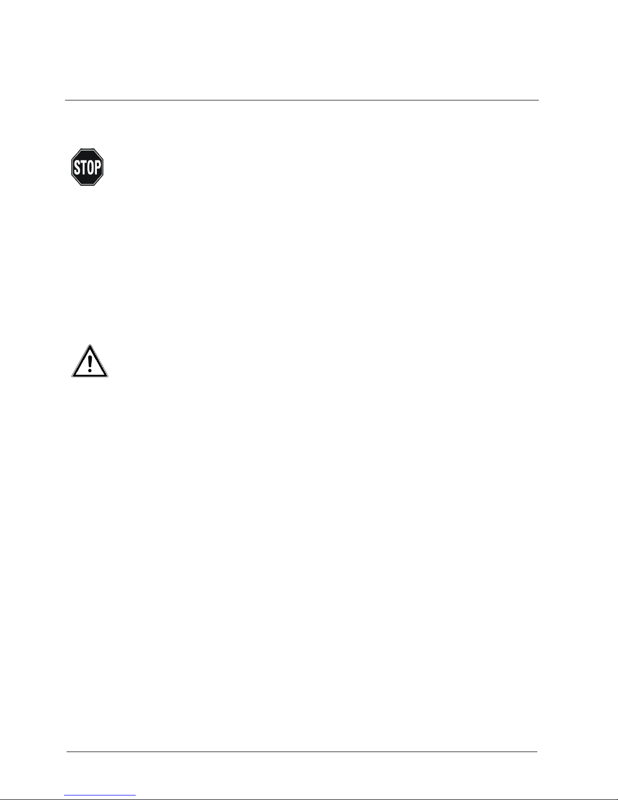
Installation example of an SinorixTM al-deco STD extinguisher system:
Key to the major components:
1 Extinguisher container CO
2
7 Detection line steel, D=6x4
2 CO2 valve (IHP) 8 Pneumatic detection tube LIFDES
3 Pressure switch 1 9 Manual start with pressure gauge
4 Ball valve for activation / 10 Detection line end adapter
deactivation of the extinguisher system 11 Extinguisher line
5 DIMES measurement probe (integrated into valve) 12 Extinguisher nozzles
for the CO2 volume control 13 Distributor block with pressure switches 2 and 3
6 Communication interface 14 Valve protection cap
14
Page 9
Description of the extinguisher system
9
Building Technologies
A54475-A1-A2_EN_05.docx
Fire Safety
01.2018
2.3 Components of the extinguisher system
Detection tube (LifdesTM)
Warning!
The LifdesTM pneumatic detection tube must not be damaged under any circumstances! It
must not be kinked or crushed! If this happens, the extinguisher system may not switch on in
case of fire, which could lead to serious damage to property and injury to persons.
Do not expose the LifdesTM pneumatic detection tube within the machine tool to any direct
source of heat!
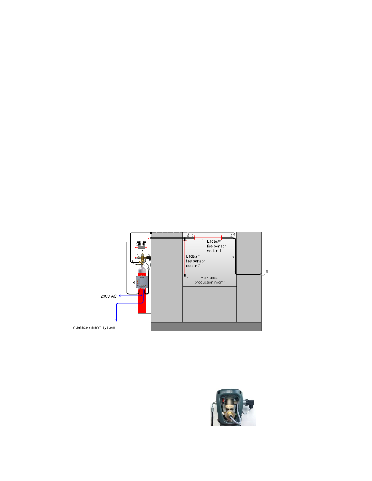
Note!
The pneumatic detection tube bears the inscription “LIFDES – do not cut kink crush“.
The heart of the extinguisher system is a special high-tech polymer tube.
It is positioned in the object to be protected according to the fire risk, and
is connected to the extinguisher cylinder via a valve, and is permanently
under pressure. It serves as a detection tube, i.e., as a linear sensor.
As soon as the ambient temperature rises above 110 °C, the tube will
burst. As a result, there is a pressure drop in the system and the valve of
the extinguisher container will open at virtually the same time.
Valve
The SinorixTM al-deco STD extinguisher system is fitted with a specially
developed high-pressure valve. When the detection tube bursts, the
valve opens and starts the extinguishing procedure.
(See Chapter „5 What happens when there’s a fire?“).
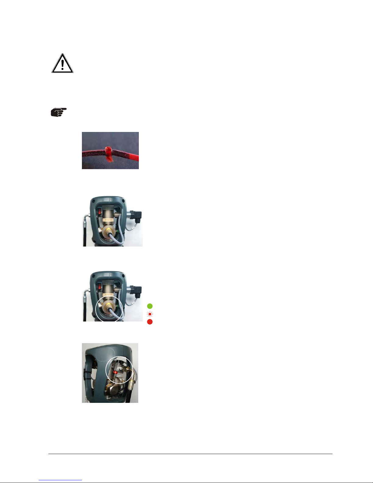
DIMES
A DIMES (Digital Measuring System) is integrated into the valve. It
ensures the constant monitoring of the quantity of extinguisher in the
extinguisher container and passes this data on to the communication
interface.
The sensor also indicates the status of the extinguisher container via an
LED, as follows:
Filling level > 80% (green)
Technical alarm/fault (blinking red)
Extinguisher container empty or filing level < 80% (red)
Ball valve
A ball valve is fitted directly on the valve. This can be used to activate or
deactivate the extinguisher system (see Chapter „3.3 Deactivating/
activating the system“). The position of the ball valve will be forwarded to
the Communication Interface.
The improper opening of the ball valve is prevented by a locking pin.
Page 10
Description of the extinguisher system
10
Building Technologies
A54475-A1-A2_EN_05.docx
Fire Safety
01.2018
Pressure switch 1
A pressure switch is mounted on the valve, which is tripped when the
pressure in the detection tube falls, the ball valve is opened or
extinguishing procedure is initiated. The pressure switch can only be
brought back to its initial position when the extinguisher container has
been refilled or replaced (see Maintenance and Repair Instructions).
Pressure switch 1 (DS1) only drives Relay 1 (fire alarm). This alarm is
made available as 2 NC contacts on Terminals 22/23 and 24/25. These
outputs are intended for additional functions such as alarming the fire
alarm centre, and should not be used for the Machine Emergency Stop.
Pressure switches 2 + 3
Pressure switches 2 + 3 are bolted onto a common distributor block.
This distributor block is normally mounted on the extinguisher container
bracket or, in individual cases, on the machine housing in the
immediate vicinity of the extinguisher container. Pressure switch 2
(DS2) takes over the „Machine EMERGENCY STOP“ function and is
connected directly from the input terminals 10/11 to the output
terminals 12/13 within the Alarm interface. Pressure switch 3 (DS3) is
responsible for the alarm (optical/acoustic) and data recording
functions. Both pressure switches are tripped when the pressure in the
detection tube falls. The pressure switches can only be brought back to
their initial position when the extinguisher container has been refilled or
replaced (see Maintenance and Repair Instructions).
Extinguisher line including the extinguisher nozzles
If the valve of the extinguisher container is opened, the extinguisher
flows through a separate extinguisher line and the correspondingly
positioned extinguisher nozzles, and floods the machine tool (see
Chapter „5 What happens when there’s a fire?“).
Communication Interface
The communication interface is mounted on the extinguisher container
or on the machine tool. It is supplied by the 115 VAC, 230 VAC or 24
VDC and is connected to the DIMES, the ball valve monitoring and
den the pressure switches DS1 + DS3.
It indicates the status of the extinguisher system by means of various
optical and acoustic signals (see Chapter „3.1 Communication
Interface “). If there is a power failure, a battery ensures the problemfree operation of the communication interface for up to 12 hours (see
Chapter „3.5 Loss of mains power“).
DS2
DS3
Page 11

Description of the extinguisher system
11
Building Technologies
A54475-A1-A2_EN_05.docx
Fire Safety
01.2018
Flashing light/ Acoustic alarm
If the systems starts to extinguish a fire, the flashing light (1) on the
communication interface lights up and an acoustic signal (2) sounds. If
the remaining amount of extinguisher falls below 70% of the full level,
the flashing light will light up every 60 minutes for 8 seconds (see
Chapter „5 What happens when there’s a fire?“).
Data storage unit + USB
The data specific to the system and data regarding services and refills
is stored in the Communication Interface. In addition, all safety relevant
data is recorded in a data storage unit (Black-Box). All this data can be
read out with a laptop at any time using a USB interface
Manual start with pressure indicator
In order to also be able to start the extinguisher system manually, a
Manual Start is fitted near the operating panel of the machine tool (see
„System started (fire alarm)“).
2
1
Page 12

Extinguisher system
12
Building Technologies
A54475-A1-A2_EN_05.docx
Fire Safety
01.2018
3 Extinguisher system
3.1 Communication Interface
The following table gives you an overview of the various states that your extinguisher system can be
in.
Key
Incidents
Operation
Battery
operation
System
tripped (fire
alarm)
System
inactive
Loss of
extinguisher
Reset alarm
after tripped
Operation (green)
Battery operation
(yellow)
System tripped
(red)
System inactive
(yellow)
Extinguisher loss
(red)
Reset alarm (key
switch)
Key removed
Key removed
Key
removed
Key removed
Key removed
Key inserted in
horizontal
position
(locked)
Flashing light
constant.
every 10 min.
for 6 sec.
every 60 min.
for 8 sec.
Acoustic signal
constant
every 10 min.
for 6 sec.
every 60 min.
for 8 sec.
blinking LED illuminated LED LED off
3.2 Operational status
Note!
This operating manual presupposes that the system has been installed by a licensed and
authorised installer or by the manufacturer. The installer will carry out the work within the
framework of the valid regulations and directives, and is liable for the quality of the
installation. This operating manual contains an Handover and Instruction Protocol (see
Chapter 8), which must be completely filled in by the installer and must be legally signed
by the operator. This protocol serves as a certification of the correct installation,
commissioning and handover of the extinguisher system to the operator.
The correct inspection of the extinguisher system in accordance with the Handover and
Instruction Protocol is the precondition for the safe and problem free operation of the
extinguisher system.
Page 13

Extinguisher system
13
Building Technologies
A54475-A1-A2_EN_05.docx
Fire Safety
01.2018
Checking the extinguisher system
Warning!
The activation of the extinguisher system may only be carried out by authorised personnel.
The ball valve must point parallel to the tube direction.
It is opened, and the extinguisher system is activated.
The key on the Communication Interface must be pulled out.
The Communication Interface indicates the active state as follows:
Operation (green)
The system is now in operation.
3.3 Deactivating/activating the system
Danger to life!
Before you or any other person enter the protected area of the machine tool to carry out
maintenance work, the extinguisher system must first be deactivated by authorised personnel! If
the pneumatic LifdesTM detection tube is accidentally damaged, carbon dioxide (CO2) will flow
out of the extinguisher system and you must protect yourself and other persons, as this is
deadly in high doses!
Warning!
The activation and deactivation of the extinguisher system may only be carried out by
authorised personnel. They are responsible for ensuring that the extinguisher system is
reactivated again before the start of the production.
Page 14
Extinguisher system
14
Building Technologies
A54475-A1-A2_EN_05.docx
Fire Safety
01.2018
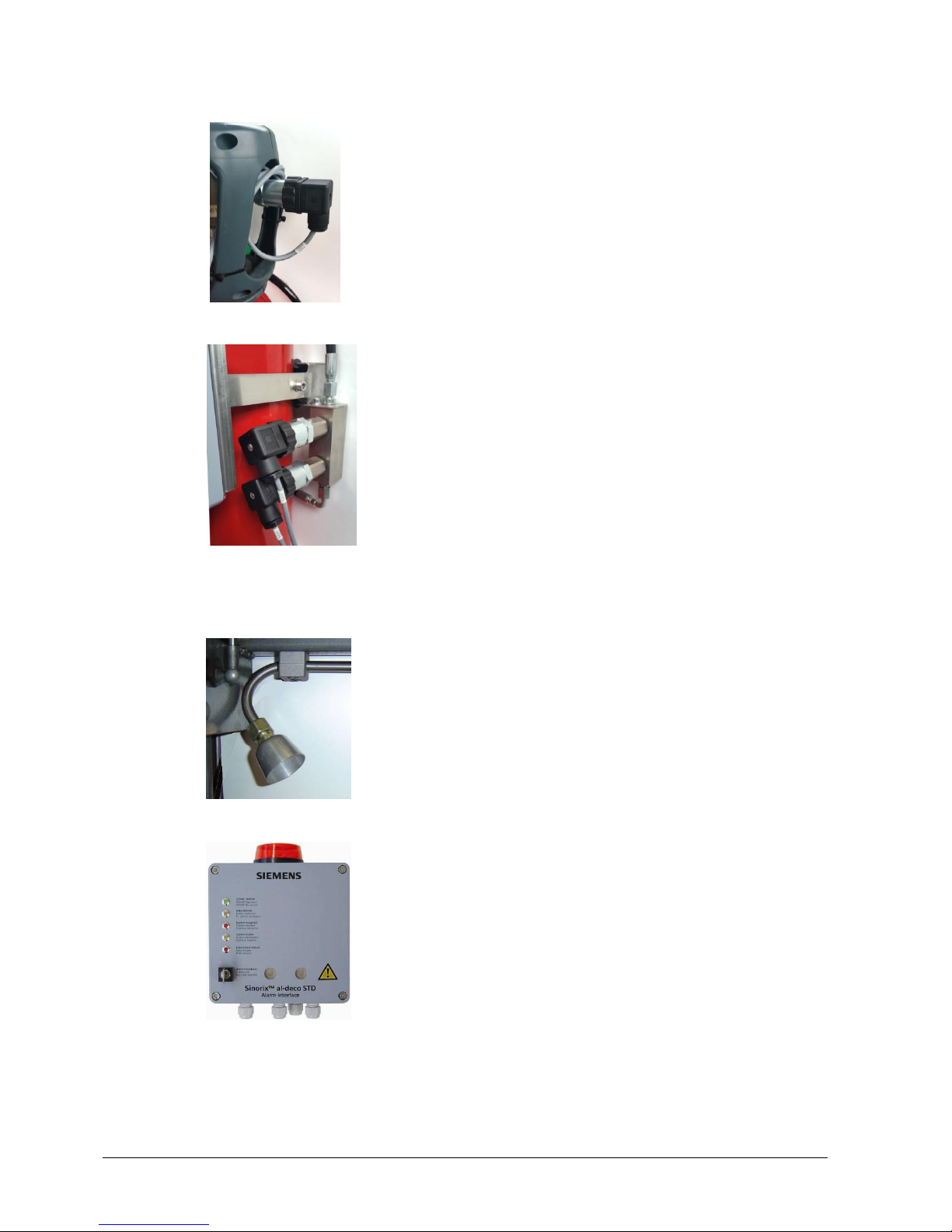
Deactivating the extinguisher system
Pull out the interlock (1).
Turn the ball valve through 90° (2).
The ball valve is closed, and the extinguisher system is
deactivated.
The communication interface indicates the inactive state as follows:
Operation (green)
Extinguisher system inactive
(yellow)
Acoustic signal
Every 10 minutes for 6 seconds.
Flashing light
Every 10 minutes for 6 seconds.
The LifdesTM pneumatic detection tube is still under pressure. If there is damage to the tube,
however, the loss of pressure will not initiate an extinguishing procedure.
Reactivating the extinguisher system
Warning!
The activation of the extinguisher system may only be carried out by authorised personnel. The
latter is responsible for ensuring that the extinguisher system is activated again before the start
of the production.
Important!
Check the pressure in the pneumatic LifdesTM detection tube. A pressure gauge (manometer) is
mounted on the manual start.
1
2
Page 15

Extinguisher system
15
Building Technologies
A54475-A1-A2_EN_05.docx
Fire Safety
01.2018
Check that the indicator of the gauge is in the green area.
Danger to life!
If the pressure indicator is outside the green area of the gauge, you must not reactivate the
extinguisher system under any circumstances! If it is nevertheless activated, the fire
extinguishing operation will be started and the cylinder will be emptied. The system can then
only be switched active again after the container has been replaced (see Maintenance and
Servicing Instructions).
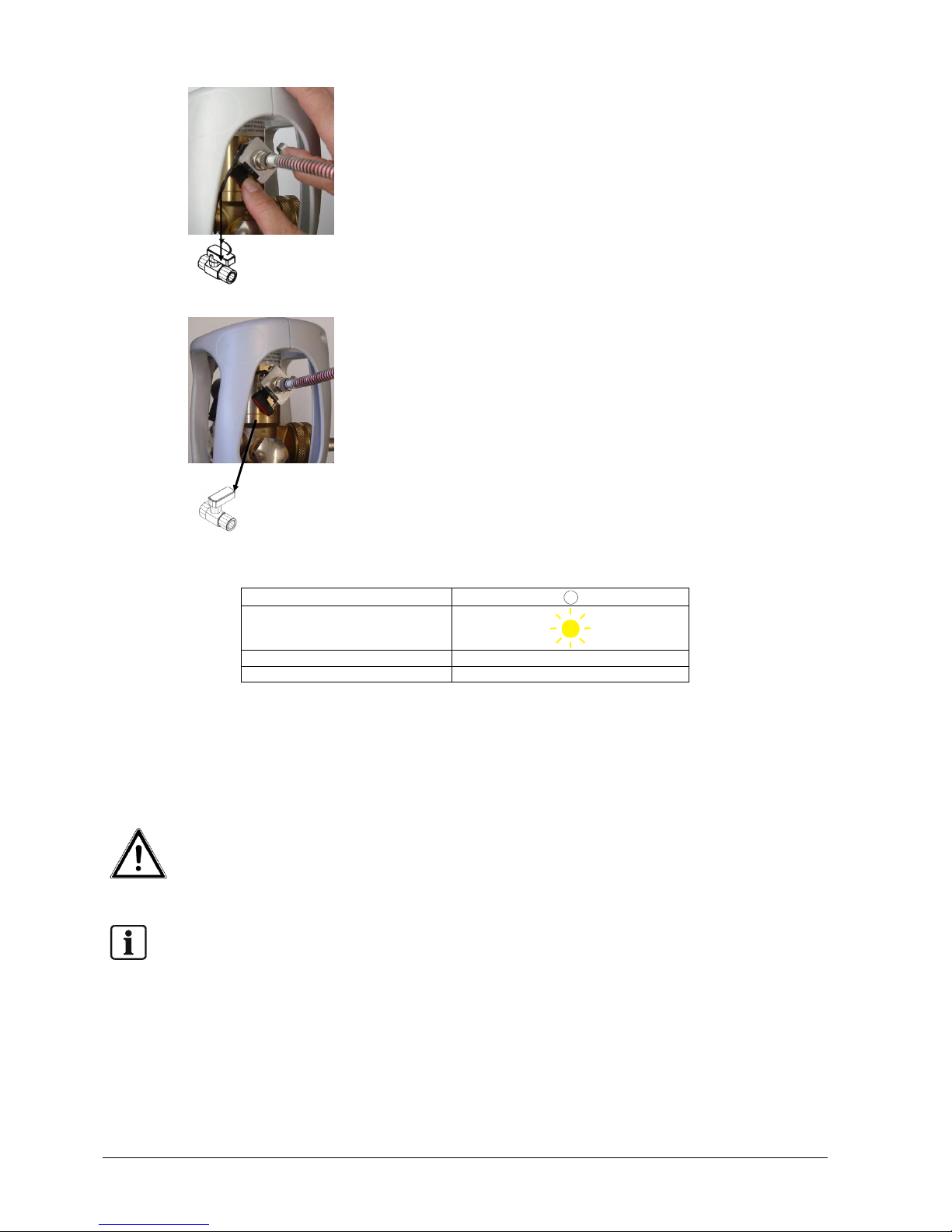
If the pressure indicator is in the green area of the gauge,
Pull out the locking pin (1).
Turn the ball valve through 90° (2), so that it points parallel to the
direction of the tube (3).
The ball valve is opened, and the extinguisher system is activated
again.
The communication interface indicates the active state as follows:
Operation (green)
The system is in operation.
Important!
Maintenance and repair work may only be carried out by authorised personnel.
3.4 Loss of extinguisher
If extinguisher leaks from the extinguisher container, and the level of extinguisher falls below the
value of 80%, this loss will be indicated by optical and acoustic signals.
The communication interface indicates the loss of extinguisher as follows:
Operation (green)
Extinguisher loss (red)
Flashing light
every 60 min. for 8
sec.
Acoustic signal
every 60 min. for 8
sec.
The optical and acoustic signals can only be deactivated by the complete refilling of the extinguisher
container (100%). Consult the „Maintenance and Repair Instructions“ document.
1 2 3
Page 16

Extinguisher system
16
Building Technologies
A54475-A1-A2_EN_05.docx
Fire Safety
01.2018
3.5 Loss of mains power (Power failure)
Important!
Any work on the communication interface, such as the replacement of the batteries, switching
on the interface on the circuit board and changing the fuses may only be carried out by
authorised persons (see Maintenance and Repair Instructions).
In case of a power failure, the function of the communication interface will be maintained for 12
hours by a battery. The detection and the fire extinguishing functions will not be affected by the
power failure, as this part of the extinguisher system works purely mechanically or pneumatically.
The communication interface indicates the current state as follows:
Operation (green)
Batter operation (yellow)
Flashing light
every 60 min. for 8 sec.
Acoustic signal
every 60 min. for 8 sec.
Page 17

Reading out the data storage unit
17
Building Technologies
A54475-A1-A2_EN_05.docx
Fire Safety
01.2018
4 Reading out the data storage unit
4.1 General information
The SinorixTM al-deco STD Com-interface has an electronic storage unit that makes various
recordings possible. In addition, all data regarding the extinguisher system installed on a machine
tool in another object is read into the interface by inputting with a PC. Both the extinguisher system
data and the data of the protected object are recorded.
The input process starts with the preparation of the system at the manufacturer's site, and is
continued up to the commissioning, service and refilling.
All incidents will be recorded in a directory that can process up to 1,000 incidents.
The input processes are carried out using a password management. All persons who have been
authorised by altrade ag to carry out entries must be in possession of a password, which will
communicated to them personally by the company management of Siemens.
For the read-out of the data by the user, a software is installed on the CD-Rom (user handbook) a
software that has to be loaded onto a PC by the user when necessary.
This software can also be downloaded over the Internet using the user password.
The interface must be connected to the PC via the USB interface.
The following description explains the entries of the user interface in detail, and explains how to
handle the input process.
It assumes that the corresponding software has been loaded onto a PC and that this is connected to
the interface by means of a USB cable.
4.2 File
Login:
In order to initialise the contact with the interface, a log-in is required, and a password is necessary
in order to complete the log-in.
This password will be provided by the manufacturer. The password is unique, and, if it is forgotten,
a new password will have to be generated by the manufacturer.
Click on Login, and wait until the new window appears with the password
Enter the user (family name) and the corresponding password (6 alphanumeric characters).
Click on OK
You are now logged in and should see your name on the top information bar.
The forms that can be printed out are listed below.
When you want to exit the program, use „Close“, but note that all data that has not been saved will
thereby be lost.
4.3 Languages
The language can be selected in the Language field.
All screens then appear in the selected language.
The entries to the fields takes no account of the selected language.
Page 18

Reading out the data storage unit
18
Building Technologies
A54475-A1-A2_EN_05.docx
Fire Safety
01.2018
4.4 Operator interface and fields
4.4.1 Operator interface password
General information:
The operator interface has already been configured at the factory, and must therefore not be
operated by the user. The following comments are therefore for information only.
The passwords have already been issued to the individual users.
A total of three user groups have been defined:
Manufacturer User passwords from the manufacturer
End user The end user only has access to the data.
He can read or print out the data. No password is necessary for this.
4.4.2 Initialising the operator interface
General information:
The initialisation of the units is carried out by the manufacturer.
Press the Save button after entering all the fields.
Field 1 System type
Requires the system model: e.g. SinorixTM al-deco STD
Field 2 System number
Is provided by the manufacturer.
Field 3 Customer number
Is provided by the manufacturer.
Field 4 Serial number of the interface
Is provided by the manufacturer.
The serial number is noted on the interface.
Field 5 Cylinder data
Is provided by the manufacturer
The cylinder number and the valve batch number are recorded
Field 6 Remarks
Can only be used by the manufacturer.
For free use, maximum 16 characters
Field 7 Date
This field is configured by the manufacturer.
When saving, the family name of the user who last worked on the system will be automatically
recorded.
Page 19

Reading out the data storage unit
19
Building Technologies
A54475-A1-A2_EN_05.docx
Fire Safety
01.2018
4.4.3 Commissioning
General information:
The registration of the data will be carried out by the commissioning technician after installation at
the customer's premises.
Field 1 Date
This field is configured by the manufacturer.
Field 2 Machine type
The type and the manufacturer of the machine and/or a specific designation will be
recorded.
The registration is carried out by the commissioning technician.
Field 3 Machine number
The manufacturer and the serial number of the machine will be recorded by the
commissioning technician.
Field 4 Filling pressure test measurement (bar)
The current filling pressure of the LifdesTM with the ball valve closed. An electronic
pressure gauge (manometer) is used for this. The entry will be carried out by the
commissioning technician.
Field 5 Filling pressure after 20 minutes (bar)
The filling pressure after 20 min from the LifdesTM with the ball valve closed are recorded
. An electronic pressure gauge (manometer) is used for this.
The recording is carried out by the commissioning technician.
Field 6 Filling level in %
The filling level is recorded by the commissioning technician according to the
measurement with DIMES (three characters before the decimal point and tow characters
after).
Field 7 Remarks
For free use
Length of the field Max. 16 characters
Use of this field is not obligatory
Page 20

Reading out the data storage unit
20
Building Technologies
A54475-A1-A2_EN_05.docx
Fire Safety
01.2018
4.4.4 Service
General information:
The registration of the data will be carried out by the commissioning technician after installation at
the customer's premises
Field 1 Datum
This field is configured by the manufacturer.
Field 2 Machine type
The type and the manufacturer of the machine and/or a specific designation will be
recorded.
The registration is carried out by the commissioning technician.
Field 3 Machine number
The manufacturer and the serial number of the machine will be recorded by the
commissioning technician.
Field 4 Filling pressure test measurement (bar)
The current filling pressure of the LifdesTM with the ball valve closed. An electronic
pressure gauge (manometer) is used for this. The entry will be carried out by the
commissioning technician.
Field 5 Filling pressure after 20 minutes (bar)
The filling pressure after 20 min from the LifdesTM with the ball valve closed are recorded.
An electronic pressure gauge (manometer) is used for this.
The recording is carried out by the commissioning technician.
Field 6 Filling level in %
The filling level is recorded by the commissioning technician according to the
measurement with DIMES (three characters before the decimal point and tow characters
after).
Field 7 Remarks
For free use
Length of the field Max. 16 characters
Use of this field is not obligatory.
Page 21

Reading out the data storage unit
21
Building Technologies
A54475-A1-A2_EN_05.docx
Fire Safety
01.2018
4.4.5 Refilling
This screen must always be filled in if a refill takes place.
If the DIMES module inside the valve is changed, it will be necessary to register the new number.
The input takes place using a separate mask, which is opened up after the "New entry" button is
operated. After the data has been entered, click on the „OK“ button to confirm and wait until the
entry appears in the table. Exit the mask by pressing "Cancel" if necessary.
The „Load“ button displays the data already registered.
The „Edit data“ button allows corrections to the data, but only to those of the user who is currently
logged in.
After completing the correct entries, save all the data by pressing the „Save“ button .
The registration of the data will be carried out by the service technician.
Field 1 Date
This field has been configured by the manufacturer.
Field 2 Serial number DIMES
The serial number will be recorded by the service technician on the DIMES module.
Field 3 Cylinder data
The cylinder number and the valve batch number are recorded by the service technician.
Field 4 Filling pressure test measurement (bar)
The current filling pressure of the LifdesTM with the ball valve closed will be recorded by
the service technician.
Field 5 Filling pressure after 20 minutes (bar)
The filling pressure after 20 min from the LifdesTM with the ball valve closed are recorded
by the service technician.
An electronic pressure gauge (manometer) is used for this.
Field 6 Filling level in %
The filling level is recorded by the service technician according to the measurement with
DIMES.
Field 7 Remarks
For free use
Length of the field Max. 16 characters
Use of this field is not obligatory
4.5 Incident
The incidents will be automatically recorded with sequential numbers and the date and time. The
highest number always represents the latest incident and is displayed as the first field.
The normal conditions are shown with a green background, and the abnormal conditions with red.
The page is provided with a scroll mode that always shows the latest status.
Non-current states will be pushed into the background, but will be taken into account when printing
out.
The „Load“ button shows the current status in each case.
No password is needed to read or print out the incidents.
4.6 Extras
The Time and Date window indicates the last incident.
By actuating „Update“, the time will be set to the „Actual status“.
Resetting the Time and Date requires access by the Administrator.
Page 22

What happens when there’s a fire?
22
Building Technologies
A54475-A1-A2_EN_05.docx
Fire Safety
01.2018
5 What happens when there’s a fire?
Danger to life!
If there is a fire, and the extinguisher system is triggered, you must immediately leave the
room, or must keep at least 5 metres away from the area! Carbon dioxide (CO2) flows out
of the installation and you must therefore protect yourselves and other persons, as this is
deadly in high doses!
Keep the area to be protected closed for the time being. Where necessary, hold a suitable
fire extinguisher ready for extinguishing any remaining fires, and call the fire brigade.
Important!
Inform the security officer of your company.
5.1 System tripped (fire alarm)
If a fire occurs on the machine tool, the following sequence takes place:
As soon as the ambient temperature rises above 110 °C, the pneumatic LifdesTM detection
tube bursts.
As a result, there is a pressure drop in the LifdesTM pneumatic detection tube and the valve of
the extinguisher container opens at virtually the same time.
The extinguisher flows through a separate extinguisher line and the correspondingly
positioned extinguisher nozzles to the source of the fire and floods the protected area of the
machine tool.
The EMERGENCY STOP of the machine is switched by a pressure switch using a potential-
free changeover contact.
Note!
The connection to the machine stop and/or EMERGENCY STOP must always take place.
The communication interface indicates the current status as follows:
Operation (green)
System tripped (fire alarm)
(red)
Loss of extinguisher (red)
Flashing light
constant
Acoustic signal
constant
Page 23

What happens when there’s a fire?
23
Building Technologies
A54475-A1-A2_EN_05.docx
Fire Safety
01.2018
5.2 Manual Start
If you see a fire in the machine tool before the fire alarm has been tripped, you can start the
extinguisher system manually using the Manual Start.
1
2
Rip off the yellow seal downwards (1).
Firmly hit the red button with your fist (2).
The fire alarm is started.
The communication interface indicates the current status as follows:
Operation (green)
System tripped (fire alarm)
(red)
Loss of extinguisher (red)
Flashing light
constant
Acoustic signal
constant
5.3 Acknowledging the fire alarm
Danger to life!
Always ventilate the rooms thoroughly after the extinguisher system has been tripped! Also
ventilate lower-lying rooms, as carbon dioxide is heavier than air and will flow downwards.
After a fire, the fire alarm must be acknowledged on the communication interface.
Insert the key into the key switch and turn it to the right.
The LED of the fire alarm blinks.
The acoustic signal and the flashing light stop.
The EMERGENCY STOP signal for the machine tool is reset, and the machine can continue
operation.
The key can no longer be removed in this position. If you turn the key back to the left, the signals are
activated and the machine is again switched to EMERGENCY STOP.
The communication interface indicates the current status as follows:
Operation (green)
System tripped (fire alarm)
(red)
Loss of extinguisher (red)
Flashing light
Acoustic signal
Page 24

What happens when there’s a fire?
24
Building Technologies
A54475-A1-A2_EN_05.docx
Fire Safety
01.2018
Warning!
Once the extinguisher system has been activated, no second fire will be able to be extinguished
in the same machine tool until the extinguisher system has been serviced again. This servicing
may only be carried out by Siemens or by one of the partners authorised by Siemens.
You can only remove the key if the system has been serviced, and the pressure switch can only be
returned to its initial position when the extinguisher container is full again (see Maintenance and
Repair Instructions). Only then is the communication interface reset.
5.4 Information to the installer
Following an initiation or fault on the extinguisher system, you, as the operator, must immediately
inform the installer (see Maintenance and Repair Instructions).
Page 25

Technical data
25
Building Technologies
A54475-A1-A2_EN_05.docx
Fire Safety
01.2018
6 Technical data
6.1 LifdesTM pneumatic detection tube
Tube material
Specially developed, high molecular polymer with two decisive core
characteristics:
Minimal (negligible) loss of extinguisher thanks to a diffusion
rate of almost zero
Defined burst behaviour for a defined internal pressure
Dimensions
Standard diameter external 6 mm, internal 4 mm
Trip temperature
Above 110° C at 12 - 20 bar internal pressure
Operational temperature
Constant temperature up to max. 80° C
Operating pressure
Permanent 12 - 20 bar
Burst pressure
At approx. 50 bar (20° C)
Bending radius
Min. 40 mm, recommended > 60 mm
Resistant against
UV-radiation, diesel, all commercial cooling lubricants, detergents and
most commonly-used chemicals
6.2 Communication interface
Power supply
Mains voltage 115/230 VAC, or 24 VDC, must be taken after the main
switch of the machine.
Current consumption
Max. 40 mA, fused with 63mAT
UPS
Battery 12 VDC/1.3 Ah, secure against total discharge, gas-tight, 12hours independence from the mains supply. Manufacturer: Panasonic
Type LC-R121R3PG
Optical alarm
Flashing light 12 VDC/85 mA/1 W
Acoustic alarm
Two-tone piezo buzzer, sound pressure 95 dB (3m distance)
Outputs
The signals from all three monitored states (operation, fire alarm,
leakage alarm) are available to the operator in the form of potentialfree relay contacts. Maximum load 48 VDC /0.2A
Housing
Aluminium injection-moulded housing with lid
Temperature
Ambient -5 ... +35°C
Storage -20.. +60°C
interface
A USB interface is available. The system data can be read out using
a laptop.
6.3 Disposal
The device is considered an electronic device for disposal in accordance with
the European Guidelines and may not be disposed of as domestic garbage.
Dispose of the device through channels provided for this purpose.
Comply with all local and currently applicable laws and regulations.
Page 26

Technical data
26
Building Technologies
A54475-A1-A2_EN_05.docx
Fire Safety
01.2018
Interface connections
A For storage and transport, the red plug-in bridge (BR1) is fitted to just one pin. This
protect the battery from being unnecessary discharged. After commissioning, the red
plug-in bridges (BR1) must be fitted to both pins so that the battery will go into
operation.
B The power supply to the communication interface is switched on and off with the slider
switch.
Switch right = switched on
Switch left = switched off
C USB plug for the read-out of the system data.
D Battery for bridging over losses of the mains supply for up to 12 hours. (Refer to the
Maintenance and Repair Instructions for the replacement of the battery)
E Rating plate with all the information required by the regulations
The terminal configuration can be seen from connection diagram on the following page.
C
B A D
E
C
Page 27

Technical data
27
Building Technologies
A54475-A1-A2_EN_05.docx
Fire Safety
01.2018
NC
green
K10
yellow
K11
IN
J9/10
J9/11
Pushbutton DS2
Machine Emergency
Stop
K12
J9/12
K13
J9/13
OUT
Output for machine Emergency
Stop (compulsory)
NC
green
K08
white
K09
J9/8
J9/9
Pushbutton DS1
Fire alarm
Additional outputs
Pushbutton DS3
Fire alarm
GND Fire alarm (FIREREL./DS1)
IN Fire alarm (FIREREL./DS1)
NC
white
K06
brown
K07
J9/6
J9/7
GND Fire alarm (FIRE / DS3)
IN Fire alarm (FIRE / DS3)
Shield + grey / pink
K04
grey
K05
J9/4
J9/5
GND Power supply DIMES
+12V Power supply DIMES
K02
K03
J9/2
J9/3
K01
J9/1
N
Ph
*External power supply
230VAC or 115VAC
Customer connection
EXTERNAL CONNECTIONS
Int.-No.
INTERNAL CONNECTIONS
J9/17
K18
J9/18
Error message Loss of
Extinguisher (if required)
K16
J9/16
K17
R4
R6
R5
changeover
Relay, Loss of Extinguisher (K3)
(shown as no loss)
K21
J9/21
Error message System inactive
(if required)
K19
J9/19
K20
R3
changeover
Relay, System inactive (K2)
(shown as System active)
Fire alarm System tripped
Additional output (if required)
K22
J9/22
K23
Relay, Fire alarm (K4a)
(indicated rest position =
no fire alarm DS1)
J9/23
NC
K24
J9/24
K25
J9/25
NC
Fire alarm System tripped
Additional output (if required)
Relay, Fire alarm (K4b)
(indicated rest position =
no fire alarm DS1)
K14
J9/14
K15
Relay for external consumer (K6)
(indication rest position = closed)
(Low battery point reached = open)
J9/15
NC
K26
J3/1
K27
K28
J3/3
K29
J3/2
J3/4
Bridge
K27 to K28 with 230 VAC power supply
Bridge 115 VAC
K26 to K28 and K27 to K29 with
115 VAC power supply
K31
K30
*External power supply 0V (GND)
External power supply +24V
NC
blue
K34
yellow
K35
System inactive
Factory connection
NC
red / blue
K32
white / green
K33
Extinguisher loss
Factory connection
We recommend 24 Volts DC (K30/
K31), or otherwise 230 Volts AC as
the power supply
Attention! Only one of these 2
variantes may be connected at any
time!
*
Terminal No.
Customer connections Factory connections
R8
R8
R7
R7
J9/20
R1
R2
Page 28

Maintenance / Guarantee
28
Building Technologies
A54475-A1-A2_EN_05.docx
Fire Safety
01.2018
7 Maintenance / Guarantee
7.1 Maintenance of the SinorixTM al-deco STD fire extinguisher systems
The system has been designed so that it can be operated without external maintenance. This means
that, supported by the document „Maintenance and Repair Instructions “,the operator should be able
to carry out routine checks and put the machine back into service after a fire himself.
In order to be able to guarantee the operational reliability of the extinguisher system, the extinguisher
system must be serviced every 12 months.
7.2 Guarantee / Warranty
The guarantee period commences with the handover of the extinguisher system to the operator.
Page 29

Handover and Instruction Report for the Operator
29
Building Technologies
A54475-A1-A2_EN_05.docx
Fire Safety
01.2018
8 Handover and Instruction Report for the Operator
To Company: _____________________________________________________________________
Person responsible: _____________________________________________________________________
Street: _____________________________________________________________________
Post Code/Town: _____________________________________________________________________
Tel. / Fax No.: _____________________________________________________________________
Extinguisher system data
Installation check
Checked
Remarks
Day of Installation:
Fittings of the detection line:
Application:
Fittings of the extinguisher line:
Extinguisher system No.:
Function of the pressure switch:
Number of container:
Alarm interface connected:
Weight of container:
Manual Start mounted:
Serie No. of Interface:
Ventilation shut-off valve locked:
Serie No. LifdesTM
Sealing of the system:
Batch No. Valve:
Information/Warning notices:
System activated:
Machine data
Operating Handbook delivered:
Machine manufacturer:
„Alarm reset“ key handed over:
Machine model:
Serial number:
230 VAC & connected:
Internal number:
EMERGENCY STOP connected:
The operator hereby confirms the following points for the manufacturer of the extinguisher system
and/or the machine manufacturer:
The instruction course for the employees of the operator regarding the extinguisher system was carried out
according to the Operating Handbook. The instruction course was completely understood and the
information will be passed on to the respective superiors and colleagues who were not present.
That he has taken over the extinguisher system installed by the manufacturer/installer, including any
agreed deviations from the Directives for the Planning and Installation.
That the installation took place on the machine stated in the report.
That the manufacturer/installer of the extinguisher system will accept no liability for modifications, improper
damage or repair work on the extinguisher system that is carried out by non-authorised persons.
That the manufacturer/installer also accept no liability for damage caused by an improper release of the
"EMERGENCY STOP" of the machine and the ventilation when the extinguisher system is tripped by fire
That the connection of the alarm function must be carried out by machine manufacturer.
That the legal signatory of the operator has received the Operating Handbook (A54475-A1-A2.doc),
together with all the relevant oral and written instructions that are necessary for the proper operation of the
extinguisher system. They have noted that the relevant reports are an integral component of the Operating
Handbook (Chapter 8).
The legal signatory of the operator have taken note of the information regarding the oxygen concentration
and know that this relates to a component part of DGUV Rule 105-001.
The guarantee period starts after the hand-over of the system to the operator.
Page 30

Handover and Instruction Report for the Operator
30
Building Technologies
A54475-A1-A2_EN_05.docx
Fire Safety
01.2018
Confirmation of the extinguisher system manufacturer/installer:
The manufacturer/installer of the extinguisher system hereby confirms that the extinguisher system has
been designed and constructed according to the valid statutory directives based on DIN 14497 and
according to the latest state-of-the-art.
The extinguisher system has been handed over in a fully functional condition (up to the interface for the
alarm interface).
Calculation of the oxygen concentration according to DGUV Rule 105-001:
The CO2 concentration of the breathable air in the installation area may not exceed 5%.
The currently measured room volume in the installation area amounts to approx. ______ m3
The total gas concentration at the tripping of the extinguisher system in the installation area currently amounts
to ________ Volume %
Formula for the calculation of the CO2 concentration in %
CO2 gas volume = Total weight of CO2 = CO2 gas volume in m3
2
CO2 proportion = CO2 gas volume (m3) x 100 (%) = CO2 concentration in %
Room volume (m3)
1 kg CO2 corresponds to approx. 0.5 m3 CO2 . The actual weigh of CO2 is quoted on the extinguisher container.
If the calculation of the oxygen concentration according to DGUV Rule 105-001cannot be carried out, the room
volume must be quoted as the length, width and height. The calculation will be subsequently carried out by the
manufacturer of the extinguisher system.
Length: __________________ Width: ____________________ Height: ________________________
Remarks: __________________________________________________________________________
__________________________________________________________________________
__________________________________________________________________________
__________________________________________________________________________
__________________________________________________________________________
______________________________________ __________________________________________
Place / Date Stamp + Signature of Operator
_____________________________________ __________________________________________
Place / Date Signature of Manufacturer/Installer
Handover executed by (company):
_____________________________________ __________________________________________
Place / Date Stamp & Name in block capitals and signature
Page 31

Page 32

Issued by
Siemens Switzerland Ltd
Building Technologies Division
International Headquarters
Theilerstrasse 1a
CH-6300 Zug
Tel. +41 58 724 2424
© Siemens Schweiz AG, 2018
Delivery possibilities and technical changes reserved.
www.siemens.com/buildingtechnologies
Document no.
A54475-A1-A2.doc
Manual SinorixTM al-deco STD
Edition
01.2018
 Loading...