

SIMATIC S5
SINEC L2 Interface of the S5-95U Programmable Controller
Manual
EWA 4NEB 812 6112-02a
Edition 02
STEP ® SINEC ® and SIMATIC ® are registered trademarks of Siemens AG.
Copyright© Siemens AG 1993
Subject to change without prior notice.
The reproduction, transmission or use of this document or its contents is not permitted without express written authority. Offenders will be liable for damages. All rights, including rights created by patent grant or registration of a utility model or design, are reserved.
Preface
| System Description | 1 |
|---|---|
| Installation Guidelines | 2 |
| Start-Up, Tests, and Diagnostics | 3 |
| Data Transmission Using a Standard Connection | 4 |
| Integrated Standard Function Blocks, L2-SEND and L2-RECEIVE | 5 |
| Data Transmission Using PLC to PLC Connections | 6 |
| Data Transmission Using Cyclic I/O (ZP) | 7 |
| Data Transmission by Accessing Layer 2 Services | 8 |
| Programmer Functions Over the SINEC L2 Network | 9 |
| Appendices |
A/B/C/
D/F |
Index
Table of Contents
Page
| Preface | |||||||
|---|---|---|---|---|---|---|---|
| 1 | System | n Description | 1 | - | 1 | ||
| 1.1 | Communications in Industry | 1 | - | 1 | |||
| 1.2 | The SINEC L2 Local Area Network | 1 | - | 3 | |||
| 1.3 | Procedure for Accessing the SINEC L2 Network | 1 | - | 4 | |||
| 1.4 | Assigning Parameters for the L2 Interface of the S5-95U | 1 | - | 8 | |||
| 1.5 | Types of Data Transmission for the S5-95U | 1 | - ' | 13 | |||
|
1.6
1.6.1 1.6.2 1.6.3 |
Physical Bus Characteristics and Installation Techniques for the SINEC L2 Network RS 485 Transmission Technology Fiber Optics Transmission Technology Mixed Configuration of RS 485 and Fiber Optics Transmission Technology |
1
1 1 |
21
21 25 28 |
||||
| 2 | Installa | ation Guidelines | 2 | - | 1 | ||
| 2.1 | Basic Configuration | 2 | _ | 1 | |||
| 2 | - | ||||||
| 2.2 | Installing a SINEC L2 Bus Segment | 2 | - | 2 | |||
|
2.2
2.3 2.3.1 2.3.2 2.3.3 |
Installing a SINEC L2 Bus Segment Linking Bus Segments with the L2 Repeater Electrical Design of the SINEC L2 Repeater RS 485 Connecting the Supply Voltage Connecting Bus Segments |
2
2 2 2 2 2 |
- |
-
2 4 5 6 |
|||
|
2.2
2.3 2.3.1 2.3.2 2.3.3 2.4 |
Installing a SINEC L2 Bus Segment Linking Bus Segments with the L2 Repeater Electrical Design of the SINEC L2 Repeater RS 485 Connecting the Supply Voltage Connecting Bus Segments Routing Cables |
2
2 2 2 2 2 2 2 |
2
4 4 5 6 8 |
||||
| 3 |
2.2
2.3 2.3.1 2.3.2 2.3.3 2.4 Start-U |
Installing a SINEC L2 Bus Segment Linking Bus Segments with the L2 Repeater Electrical Design of the SINEC L2 Repeater RS 485 Connecting the Supply Voltage Connecting Bus Segments Routing Cables Ip, Tests, and Diagnostics |
2
2 2 2 2 2 2 2 2 3 |
2
4 4 5 6 8 1 |
|||
| 3 |
2.2
2.3 2.3.1 2.3.2 2.3.3 2.4 Start-L 3.1 |
Installing a SINEC L2 Bus Segment Linking Bus Segments with the L2 Repeater Electrical Design of the SINEC L2 Repeater RS 485 Connecting the Supply Voltage Connecting Bus Segments Routing Cables Installing and Mode of Operation of the Programmable Controller |
2
2 2 2 2 2 2 2 2 2 3 3 |
2
4 4 5 6 8 1 2 |
|||
Page
|
3.3
3.3.1 3.3.2 3.3.3 |
Starting Up a System Suggestions for Configuring and Installing the Equipment Prerequisites for Starting Up the S5-95U as a SINEC L2 Station System Startup Diagnostics and Procedures |
3
3 3 3 |
-
- - |
5
5 6 7 |
|
|---|---|---|---|---|---|
|
3.4
3.4.1 3.4.2 3.4.3 3.4.4 3.4.5 |
FMA Services Principle of Operation The Types of FMA Services Assigning Parameters in DB1 for the FMA Services Managing of all FMA Services with FB222 Reading Out a List of All Active Stations on the Network |
3
3 3 3 3 |
- *
- * - * |
10
10 12 13 14 |
|
|
3.4.6
3.4.7 3.4.8 3.4.9 |
(LAS_LIST_CREATE) Reading the Status of Another Station (FDL_STATUS) Reading Updated Bus Parameters (READ_VALUE) Reading Out Available Token Hold Time When Receiving the Token (TIME_TTH_READ) Reading Out the Event Message (MAC_EVENT) |
3
3 3 3 3 |
17
19 21 24 26 |
||
| 4 | Data 1 | Transmission Using a Standard Connection | 4 | - | 1 |
| 4.1 | Features of a Standard Connection | 4 | - | 1 | |
| 4.2 | Assigning Parameters in DB1 of the S5-95U for Data Exchange with Standard Connections | 4 | - | 3 | |
| 4.3 | Transmitting Data | 4 | - | 5 | |
| 4.4 | Receiving Data | 4 | - | 7 | |
| 4.5 | Programming Example for Data Transmission via a Standard Connection | 4 | - | 9 | |
| 4.6 | Broadcast Request ("Transmit to All") | 4 | - ' | 14 | |
| 5 | Integr | al Standard Function Blocks L2-SEND and L2-RECEIVE | 5 | - | 1 |
| 5.1 | Parameters for L2-SEND and L2-RECEIVE | 5 | - | 2 | |
| 5.2 | Direct and Indirect Parameter Settings for the L2 Function Blocks | 5 | - | 4 | |
| 5.3 | Parameter Assignment Error Byte (PAFE) | 5 | - | 5 | |
| 5.4 | Status Byte | 5 | - | 6 |
Page
| 6 | Data T | ransmission Using PLC-to-PLC Connections | 6 | - | 1 |
|---|---|---|---|---|---|
| 6.1 | Features of the PLC-to-PLC Connections | 6 | - | 1 | |
| 6.2 | Assigning Parameters in DB1 of the S5-95U for Data Exchange with PLC-to-PLC Connections | 6 | - | 4 | |
| 6.3 |
Programming Example for Data Transmission via PLC-to-PLC Connections
Using Standard Function Blocks |
6 | - | 6 | |
| 7 | Data T | ransmission Using Cyclic I/O | 7 | - | 1 |
| 7.1 | Features of Cyclic I/O | 7 | - | 1 | |
| 7.2 | Assigning Parameters in DB1 of the S5-95U for Data Exchange with Cyclic I/O | 7 | - | 4 | |
| 7.3 | Controlling Data Transmission in the Control Program | 7 | - | 7 | |
| 7.4 | Programming Example for Data Transmission via Cyclic I/O | 7 | - ' | 12 | |
| 8 | Data T | ransmission by Accessing Layer 2 Services | 8 | - | 1 |
| 8.1 | Characteristic Features of Layer 2 Access Data Transmission | 8 | - | 2 | |
| 8.2 | Types and Characteristic Features of the Layer 2 Services | 8 | - | 5 | |
| 8.3 | Assigning the S5-95U Parameters for Data Communications | 8 | - | 9 | |
| 8.4 | FBs for Managing All Layer 2 Services | 8 | - ' | 11 | |
| 8.5 | Sending Data to a Station (SDA Service) | 8 | - ' | 15 | |
| 8.6 | Sending Data to Several Stations (SDN) | 8 | - 1 | 19 | |
| 8.7 | Holding Data for Fetching Once Only by a Station (RUP_SINGLE Service) | 8 | - : | 23 | |
| 8.8 | Holding Data Ready for Fetching Several Times Over by One or More Stations (RUP_MULTIPLE) | 8 | - 2 | 26 | |
| 8.9 | Sending Data and Fetching Data from a Station (SRD Service) | 8 | - : | 29 |
Page
| 9 | Programmer Functions Over the SINEC L2 Network | |||||
|---|---|---|---|---|---|---|
| 9.1 | Programmer Functions | 9 | - | 2 | ||
| 9.2 | Selecting the L2 Interface | 9 | - | 3 | ||
| 9.3 | Entering Defaults | 9 | - | 4 | ||
| 9.4 | Editing a Path | 9 | - | 5 | ||
| 9.5 | Setting the L2 Basic Parameters on the Programmer | 9 | - 1 | 10 | ||
| 9.6 | Activating an Editing Path | 9 | - | 10 | ||
Appendices
| Α |
DB1 Parameters, DB1 Parameter Assignment Errors,
Calculation of Target Rotation Time |
Α | - | 1 |
|---|---|---|---|---|
| В | SAP Numbers / Job Numbers | в | - | 1 |
| С | List of Abbreviations/Glossary | С | - | 1 |
| D | List of Accessories and Order Numbers | D | - | 1 |
| Е | Technical Specifications; Cycle Delay Times of the PLC Caused by SINEC L2 Operations | Е | - | 1 |
| F |
S5-95U Communications Matrix and Emulation of Types of Data
Transmission in Layer 2 with S5-95U |
F | - | 1 |
Index
How to Use This Manual
The S5-95U programmable controller with SINEC L2 interface can communicate with SIMATIC S5 controllers and other control devices via the SINEC L2 bus system.
To use the SINEC L2 interface to its full capacity, you need detailed information.
This manual contains descriptions for installing and operating the following programmable controllers as SINEC L2 stations:
- S5-95U, Order No. 6ES5 095-8MB01
- S5-95U, Order No. 6ES5 095-8MB02
The manual does not provide information on the performance of other controllers on the L2 bus. Only special features of the S5-95U pertaining to data interchange with the CP 5430 communications processor are mentioned.
Experience in configuring and starting up bus-type LANs is helpful, though not necessary, to work with this manual successfully.
This section is intended to make it easier for you to use the manual.
Contents of This Manual
• Chapter 1
This chapter provides an overview of the applications, performance capabilities, operation principle, basic terminology, and transmission physics of the SINEC L2 bus system. This chapter characterizes the possible types of data transmission and specifies and explains the selection criteria for special applications.
Chapter 2
This chapter specifies the installation procedures that you should follow to ensure that your S5-95U controller functions properly as a station on the SINEC L2 bus.
Chapter 3
This chapter summarizes information that you need to start up your S5-95U controller as a station on the SINEC L2 bus. You will also discover how to recognize faults in the controller and find out what tests and diagnostics are available to you.
• Chapters 4, 5, 6, 7 and 8
These chapters use examples to describe the various types of data transmission in detail.
- Chapter 9 This chapter shows you how to implement programmer functions over the LAN.
- Appendices
The appendices contain two types of information. On the one hand, you will find brief information for regular use (e.g., all the DB1 parameters); on the other hand, you will find additional information of interest to network experts (e.g., concerning the SAPs).
Each chapter begins with a brief explanation of its contents. By reading the first section of a chapter, you can determine whether the information in the chapter is important to you.
Conventions
The "S5-90U/S5-95U System Manual" and the SINEC L2 Manual - Interface of the S5-95U Programmable Controller" observe the same conventions.
All the conventions listed at the beginning of the System Manual apply also to this manual. Please refer to that Manual. Your attention is also drawn to the "Safety-Related Guidelines for the User" on page xi at the end of this chapter.
Courses
Siemens offer a wide range of training courses for SINEC users. For more information, please contact
- Informations- und Trainings-Center f ür Automatisierungstechnik AUT 959 Kursb üro Postfach 21 12 62 76181 Karlsruhe Federal Republic of Germany Tel.: (Nat. access code) 721 595-2917 or
- Your nearest Siemens representative
Reference Material
This manual contains a comprehensive description of the SINEC L2 interface of the S5-95U programmable controller. The following manuals etc. contain more detailed information on topics that are handled only briefly here:
SINEC L2 Local Area Network CP 5430 Order No. 6GK1 970-5AA00-0AA0
SINEC L2/L2F0 Manual Order No. 6GK1 970-5CA00-0AA0
Installation Guidelines: Installing the SINEC L2 Local Area Network Order No. AR 463-2-220
PROFIBUS Standard (DIN 19245) Beuth-Verlag; Berlin 1988
Bender, Klaus: Profibus Hauser-Verlag; Munich 1990
Kafka, Gerhard: Grundlagen der Datenkommunikation; Datacom-Fachbuchreihe; Pulheim 1989. (available in German only)
Stöttinger, Klaus H.: Das OSI-Referenzmodell; Datacom-Fachbuchreihe; Pullheim 1989. (available in German only)
There are correction forms at the end of this manual. Please use them to indicate any corrections, additions or suggestions you might have in the way of improvement that will benefit the next edition of the manual.
Safety-Related Guidelines for the User
This document provides the information required for the intended use of the particular product. The documentation is written for technically gualified personnel.
Qualified personnel as referred to in the safety guidelines in this document as well as on the product itself are defined as follows.
- System planning and design engineers who are familiar with the safety concepts of automation equipment.
- Operating personnel who have been trained to work with automation equipment and are conversant with the contents of the document in as far as it is connected with the actual operation of the plant.
- Commissioning and service personnel who are trained to repair such automation equipment and who are authorized to energize, de-energize, clear, ground, and tag circuits, equipment, and systems in accordance with established safety practice.
Danger Notices
The notices and guidelines that follow are intended to ensure personal safety, as well as protect the products and connected equipment against damage.
The safety notices and warnings for protection against loss of life (the users or service personnel) or for protection against damage to property are highlighted in this document by the terms and pictograms defined here. The terms used in this document and marked on the equipment itself have the following significance.
Danger
indicates that death, severe personal injury or substantial property damage will result if proper precautions are not taken.
Caution
indicates that minor personal injury or property damage can result if proper precautions are not taken.

indicates that death, severe personal injury or substantial property damage can result if proper precautions are not taken.

contains important information about the product, its operation or a part of the document to which special attention is drawn.
Proper Usage

| 1 Syster | n Description | |
|---|---|---|
| 1.1 | Communications in Industry | 1 - 1 |
| 1.2 | The SINEC L2 Local Area Network | 1 - 3 |
| 1.3 | Procedure for Accessing the SINEC L2 Network | 1 - 4 |
| 1.4 | Assigning Parameters for the L2 Interface of the S5-95U | 1 - 8 |
| 1.5 | Types of Data Transmission for the S5-95U | 1 - 13 |
| 1.6 | Physical Bus Characteristics and Installation Techniques for the SINEC L2 Network | 1 - 21 |
| 1.6.1 | RS 485 Transmission Technology | 1 - 21 |
|
1.6.2
1.6.3 |
Fiber Optics Transmission Technology
Mixed Configuration RS 485 and Fiber Optics |
1 - 25 |
| Transmission Technology | 1 - 28 |
| Figur | es |
|---|---|
| 1-1 | Hierarchy Levels in the Computer-Integrated Automation Network 1 - 1 |
| 1-2 | Bus Segment 1 - 3 |
| 1-3 | Bus Accessing Procedure |
| 1-4. | Distribution of the Target Rotation Time (1) |
| 1-5. | Distribution of the Target Rotation Time (2) |
| 1-6. | DB1 with the Default Parameters |
| 1-7 | Data Transmission Types |
| 1-8. | PLC-to-PLC Connection between Active S5-95Us |
| 1-9. | Cyclical I/O between an Active and Passive S5-95U |
| 1-10. | Standard Connection for Porting Programs from SINEC L1 to SINEC L2 1 - 19 |
| 1-11. | PLC-to-PLC Connection between an Active CP 5430 and an Active S5-95U 1 - 19 |
| 1-12. | Cvclic I/O between an Active CP 5430 and a Passive S5-95U 1 - 19 |
| 1-13. | Laver 2 Access between an Active CP 5410 and an Active S5-95U 1 - 20 |
| 1-14 | SINEC L2 Bus Segment with RS 485 Technology |
| 1-15. | SINEC L2 Network with RS 485 Technology |
| 1-16. | L2 Bus Connector with Degree of Protection IP 20 without |
| Connector for a Programmer | |
| 1-17. | SINEC L2 Network with Fiber Optic Cable |
| 1-18. | Point to Point Link via a Fiber Optic Cable |
| 1-19. | SINEC L2FO Bus Terminal SF-B/PF-B |
| 1-20. | SINEC L2FO Active Star Coupler AS 501 |
| 1-21. | Mixed Configuration with RS 485 and FO Transmission Technology 1 - 28 |
| 1-22. | Two SINECL2 Networks of the RS 485 Technology Linked |
| via Fiber Optic Cable | |
| 1-23. | SINEC L2FO SF Repeater Adapter for L2 Repeater |
| Table | 2 |
| 1-1. | DB1 Basic Parameters |
| 1-2. | Relevant Parameters for the S5-95U as an Active/Passive station |
| 1-3. | Defining the Basic Parameter Arguments for S5-95U PLCs |
| 1-4. | Defining the Arguments of the Basic Parameters for the S5-95U in |
| Conjunction with the CP 5410 and/or CP 5430-1 | |
| 1-5. | Basic Parameter Arguments for the S5-95U in Conjunction with |
| Other SIMATIC Devices | |
| 1-6. | Recommended Types of Data Transmission |
| 1-7. | Characteristics of the Various Types of Data Transmission |
| 1-8. | Types of Data Transmission for S5-95Us as Active Stations |
| 1-9. | Types of Data Transmission for S5-95Us as Passive Stations |
| 1-10. | Distance Table for RS 485 Technology |
| 1-11. | SINEC L2 Bus Terminals 1 - 23 |
| 1-12. | Technical Specifications of the Bus Cable 1 - 24 |
| 1-13. | Distance Table for Glass Fiber Optic Cable Technology 1 - 26 |
1 System Description
In this chapter, you will learn the following:
- The applications that the SINEC L2 network is suited for
- The performance capabilities that the SINEC L2 network is equipped with
- The operation principle of the SINEC L2 network
- The explanation of important basic terminology and parameters
- The types of data transmission that are possible and which criteria you use to select them
- The transmission physics that can be used
1.1 Communications in Industry
In today's modern production control systems, the installations for process automation operate in an information network that can be organized into several hierarchy levels, as illustrated in Figure 1-1.

Figure 1-1. Hierarchy Levels in the Computer-Integrated Automation Network
The following sections explain the different tasks of each of the hierarchy levels.
Definitions
Planning Level
This is where you plan orders, production strategies and production guidelines, and where the information from the production process is monitored.
Process Control Level
This is where you decide how the production will take place and how the function groups will be coordinated.
Cell Level
This level receives requests from the process control level. It consists, as a rule, of assembly cells. Each assembly cell is controlled by at least one programmable controller.
• Field Level
This is where the field devices such as sensors and actuators are. The task of these units is to make the exchange of information between control and technical process possible.
Communication Tasks Required from the Different Networks
The requirements for the planning and process control level networks differ from the requirements for the cell and field level networks as follows:
-
Communication in the planning and control levels
- Large amounts of data (range >100 bytes)
- Often no time-critical requirements
- Electromagnetic compatibility requirements matched to office environment (with additional specific measures, also for industrial environment)
- Large network expansion
- Large number of stations
- Higher connection costs acceptable
-
Communication in the cell and field levels
- Smaller amounts of data (range <100 bytes)
- Time-critical requirements (real-time requirements)
- High electromagnetic compatibility requirements (industrial environment)
- Small network expansion
- Small number of stations (range <100)
- Low connection costs
The SINEC L2 network is optimally adapted to the requirements of the cell and field levels".
1.2 The SINEC L2 Local Area Network
The SINEC L2 LAN is based on the PROFIBUS Standards (DIN 19245).
PROFIBUS ( PRO cess Fl eld BUS ) is the German process and field bus standard that is defined in the PROFIBUS Standards (DIN 19245). This standard sets up functional, electrical and mechanical characteristics for a bit-serial field network. The purpose of these standardization efforts is to be able to network programmable controllers and field devices of different manufacturers without expensive adapters. Therefore, you have the ability to mix and match components from different manufacturers, and to have them communicate with each other via the SINEC L2 network as long as the components meet the PROFIBUS Standard. The SINEC L2 network services of the S5-95U use part of the services defined in the PROFIBUS Standards.
In order to be able to use S5-95U programmable controllers as SINEC L2 stations, you need one of the following two items:
- The RS 485 bus terminal that connects SINEC L2 stations via the terminal cable with the bus cable that connects the individual bus terminals with each other.
- The SINEC L2 bus connector with bus cable that connects stations with each other.
Figure 1-2 represents a bus segment using SINEC L2 bus connectors.

Figure 1-2. Bus Segment
In order to communicate, each station must observe certain rules:
- There must be a rule for who is allowed to transmit via the common bus cable at a given time (section 1.3 "Procedure for Accessing the Bus").
- A common language must exist between two stations (section 1.5 "Types of Data Transmission").
- The electrical features of the stations must match each other ( section 1.6 "Bus Physics").
1.3 Procedure for Accessing the SINEC L2 Network
The following section discusses the basic mode of operation of the SINEC L2 network. The goal of this section is to make you familiar with terms that you will need to configure the S5-95U as a station and to assign parameters in the S5-95U.
An essential aspect of the network is the access procedure. On the SINEC L2, there are two types of stations with different access rights: active stations and passive stations.
Active Stations
- Are allowed, when they have the right to transmit data to other stations
- Are allowed to request data from other stations
Passive Stations
• Are allowed to exchange data with an active station only after being requested to do so by the latter.
Whether a station is active or passive depends on the respective unit. Simple field units such as motor control units are as a rule passive; smart units such as programmable logic controllers, on the other hand, are active.
The S5-95U can be a passive as well as an active station on the network. This is possible by setting parameters.
Station Address
Each station on the bus has a station address that you can assign by setting parameters.
Token / Right to Transmit
So that all active stations do not try to access the bus at the same time, an active station that is ready to transmit has to wait until it receives the right to access the bus. The station receives this right through a special frame, the token frame. The structure of the token frame and how its transmission is controlled will not be discussed here (refer to the PROFIBUS Standard, DIN 19245).
It is important for you to know the following:
- The token frame (and the permission to access) automatically goes from one station to the next one (according to the ascending sequence of the station addresses).
- The token frame is passed on in the logical ring: The station with the highest address passes the token frame on to the station with the lowest address. For each active station there is one token rotation cycle between token frame transmitting and token frame receiving .
A network normally contains several active and several passive stations. Figure 1-3 shows a network with three active and three passive L2 stations.

Figure 1-3. Bus Accessing Procedure
Explanations for Figure 1-3:
- The token frame is passed only from an active station to another. Stations 1, 2 and 3 are active. The token frame is passed on as follows: 1 2 3 1 2 ...
- One token cycle includes passing the token three times: 1 2 3 1.
- Stations 100, 101 and 102 are passive.
- Stations addresses 0, 4 to 99, and 103 to 126 are not assigned.
- Active stations can be assigned addresses in the range 1 to 31.
- Passive stations can be assigned addresses in the range 1 to 126.
- It is not absolutely necessary to assign the station addresses in ascending order.
Based on the mode of operation of the SINEC L2, two special cases can be deduced:
- 1) If only one station is active and all others are passive, the bus functions according to the master-slave principle.
- 2) If all stations are active, a token passing procedure is present.
Target Rotation Time
A token cycle takes a certain amount of time. You must set the maximum permissible token cycle time as target rotation time (target rotation time in DB1, TRT parameter). Even the transmission of large amounts of data must conform to the target rotation time set in DB1. In order to conform to this time, the SINEC L2 uses the following principle.
Time Management of the Network
Each active station measures the time in which it was not in the possession of the token. This time is the station's "real" rotation time, i.e., the time used up by the other stations. The station compares this measured time with the previously set target rotation time. The processing of the frame to be transmitted depends on the results of this comparison and on the priority of the message frames as follows:
The preset priority of the message frames is low for the standard connection ( chapter 4), PLC-to-PLC connection ( chapter 6) and cyclic I/O ( chapter 7). Only for layer 2 access can you decide whether the message frame is to be given high or low priority.
Possible results of the comparison between the rotation time measured (the "real" rotation time) and the target rotation time:
-
1) The "real" rotation time is shorter than the target rotation time.
- Result: All send and receive jobs in the queue are executed until the target rotation time has been reached or the jobs in the queue have been processed; first the message frames with high priority, then the message frames with low priority.
-
2) The "real" rotation time is longer than the target rotation time.
- Result: Only one more message frame with high priority is transmitted. The message frames with low priority are not transmitted until the "real" rotation time is shorter than the target rotation time in the following token cycles.
This is shown in Figures 1-4 and 1-5.
Each station measures the "real" rotation time and calculates the difference between target rotation time and "real" rotation time (= token hold time ). During this time, a station can transmit: first, the frames with high priority, then the frames with low priority. When the token hold time is used up, the station must pass the token to the next station.

Figure 1-4. Distribution of the Target Rotation Time (1)
If the transmitter has no token hold time at its disposal (see Figure 1-5), it can only transmit one frame with high priority before is has to pass the token.

Figure 1-5. Distribution of the Target Rotation Time (2)
Broadcasting
Broadcasting is when an active station sends a message frame to all active and passive stations.
Multicasting
Multicasting is when an active station sends a message frame to several active and passive stations.
1.4 Assigning Parameters for the L2 Interface of the S5-95U
You assign the parameters for the L2 interface in DB1, in the parameter block with block ID "SL2:". Irrespective of the type of data transmission you select, you must assign certain parameters (basic parameters) in DB1. The basic parameters affect only the procedures for accessing the network (see section 1.3) and not the communication mechanisms. DB1 has default settings for the basic parameters that you can use or change according to the task to be performed.
The default DB1 is illustrated in Figure 1-6.
| 1 | ||||
|---|---|---|---|---|
| 0: | KS | ='DB1 0BA: AI 0 ; 0BI: '; | ו | |
| 12: | KS | =' ; OBC: CAP N CBP '; | ||
| 24: | KS | ='N ;#SL1: SLN 1 SF '; | ||
| 36: | KS | ='DB2 DW0 EF DB3 DW0 '; | ||
| 48: | KS | =' CBR FY100 CBS FY1'; | Parameters for S5-95U | |
| 60: | KS | ='01 PGN 1 ;# SDP: N'; | functions described in the | |
| 72: | KS | ='T 128 PBUS N ; TFB: OB13'; | | > | S5-9011/S5-9511 system |
| 84: | KS | =' 100 ; #CLP: STW MW10'; | manual | |
| 96: | KS | ='2 CLK DB5 DW0 '; | manaal | |
| 108: | KS | =' SET 3 01.10.91 12:00:'; | ||
| 120: | KS | ='00 OHS 000000:00:00 '; | ||
| 132: | KS | =' TIS 3 01.10. 12:00:00 '; | ||
| 144: | KS | =' STP Y SAV Y CF 00 '; | ) | |
| 156: | KS | =' #SL2: TLN 0 STA ART'; | 1 | |
| 168: | KS | =' BDR 500 HSA 10 TRT ; | | > | Basic parameters |
| 180: | KS | ='5120 SET 0 ST 400 ; | ) | |
| 192: | KS | ='SDT 1 12 SDT 2 360 SF'; | רו | |
| 204: | KS | =' DB6 DW0 EF DB7 DW0 '; | | > | Parameters for type of data transmission |
| 216: | KS | =' KBS MB62 KBE MB63 ; '; | J | ( Chapters. 4, 6, 7 and 8) |
| 228: | KS | = ' # END ' ; | ||
Figure 1-6. DB1 with the Default Parameters
The basic parameters and their ranges are listed and explained in the following Table.
| Parameter Argument | Significance | |||||
|---|---|---|---|---|---|---|
| Block | D: SL2: | SINEC L2 | ||||
|
TLN
STA BDR HSA TRT SET ST SDT 1 SDT 2 |
n
AKT/PAS p q m s t u v |
Own station address
Own station status Baud rate Highest L2 station address on bus Target rotation time Set-up time Slot time Shortest delay time Longest delay time |
||||
| Argument | Permissible Range | Explanation | ||||
|
n
AKT/PAS p |
1 to 126
- 9.6; 19.2; 93.75; 187.5; 500; 1500 |
Station address, including 1 to 31 active S5-95U
stations AKT = active, PAS = passive Baud rate in kBaud |
||||
|
q
m s t u v |
1 to 126
256 to 1048320 0 to 494 50 to 4095 11 to 255 35 to 1023 |
Station addresses
Bit time units* Bit time units* Bit time units* Bit time units* Bit time units* |
||||
| Table 1-1. | DB1 Basic | Parameters |
|---|---|---|
| DDI Duoio | i aramotoro |
* One bit time unit is the time its takes to transmit one bit (reciprocal value of Baud rate) The arguments s, t, u, and v depend on Baud rate (see Table 1-3)
Table 1-2 shows which basic parameters are relevant for active and passive stations.
| Table 1-2. Relevant Basic Parameters for the S5-95U as an Active/Passive State | atio |
|---|
| Table 1-2. | Relevant | Basic P | aramete | ers for th | ne S5-95 | iU as an | Active | Passive | Station | า |
|---|---|---|---|---|---|---|---|---|---|---|
| Parameter | TLN | STA | BDR | HSA | TRT | SET | ST | SDT 1 | SDT 2 | |
| S5-95U activ | e | х | х | х | х | х | х | х | х | х |
| S5-95U pass | ive | х | х | х | х | х |
Rules for Setting the Basic Parameters
- TLN 0 (default) is not allowed for the S5-95U as L2 station (TLN 0 is reserved for a programmer). You must change the value for TLN 0, otherwise the programmable controller stays in the STOP mode.
- Do not delete any relevant parameters, otherwise the PLC will stay in the STOP mode! Delete any irrelevant parameters (in the case of passive S5-95Us).
-
The following basic parameters must be the same for all stations in the SINEC L2 network: BDR, HSA, TRT, SET, ST, SDT 1 and SDT 2. Always take the basic parameters of the slowest station! The slowest station is the station with the longest slot time in the SINEC L2 network.
- Example: Communications between the CP 5410, S5-95U and CP 5430-0: preset baud rate 187.5 kbaud. The CP 5430-0 with 400 bit time units has the longest slot time (default value). Set the basic parameters of the CP 5430-0 (187.5 kbaud) for all stations (see Table 1-5).
Communications with S5-95Us (homogeneous S5-95U networks)
Define the arguments of the BDR, SET, ST, SDT 1 and SDT 2 basic parameters for the S5-95U programmable controllers in DB1 (see Table 1-3).
|
Baudrate
Basic in kbaud parameters in bit time units |
9.6 | 19.2 | 93.75 | 187.5 | 500 | 1500 |
|---|---|---|---|---|---|---|
| SET | 0 | 0 | 0 | 0 | 0 | 60 |
| ST | 73 | 76 | 99 | 170 | 400 | 1000 |
| SDT 1 | 12 | 12 | 12 | 12 | 12 | 150 |
| SDT 2 | 40 | 60 | 80 | 150 | 360 | 980 |
Table 1-3. Defining the Basic Parameter Arguments for S5-95U PLCs
Example: Define the baud rate as 187.5 kbaud in DB1. This gives the other basic parameters as follows: SET 0 ST 170 SDT 1 12 SDT 2 150.
Bit time unit
You must specify certain parameters, e.g. the target rotation time, in bit time units. To calculate the times in milliseconds from the bit time units, use the following formula:
Time (in milliseconds) =
Procedure for Assigning Parameters in DB1 and the S5-95U
A default DB1 is integrated in the operating system of the S5-95U programmable controller. DB1 contains default values for parameters, including those for data exchange by means of SINEC L2.
Load the default DB1 in your programmer (function: transfer; source: PC; destination: FD (PG)).
Look for the SINEC L2 parameter block. The block ID is "SL2:".
The SINEC L2 parameter block is enclosed in comment characters (#). The programmable controller cannot interpret the SL2: parameter block in this form (Figure 1.6). Overwrite the comment characters that appear before the block ID (SL2:) and after the last SINEC L2 parameter with a blank.
Enter the parameters according to your specifications (for basic parameters and parameters for the desired communications services, see chapters 3, 4, 6, 7 and 8) in one coherent block after the block ID.
Make sure you follow the general rules for assigning parameters. Refer to the S5-90U/S5-95U Programmable Controller System Manual, section 9.1.4.
Transfer the changed DB1 to the S5-95U. The default DB1 is overwritten with the changed DB1.
If you now switch from STOP to RUN mode, the S5-95U accepts the new parameters. If the BF LED lights up (Table 3-1), you must switch from POWER OFF to POWER ON (mode selector at RUN and backup battery inserted) on the S5-95U to transfer DB 1.
Refer to Appendix A for the following information:
- The procedure for reading the DB1 parameter assignment error code and its interpretation
- The explanations to the SET, ST, SDT 1, and SDT 2 parameters. (It is not absolutely necessary to know the meaning of these parameters.)
- The procedure for setting (calculating) the target rotation time (TRT) depending on the baud rate (BDR)
Communications with the CP 5410 and/or CP 5430-1
You must set the same basic parameters BDR, SET, ST, SDT 1 and SDT 2 for the S5-95U, CP 5410 and CP 5430-1.
Define the arguments of the BDR, SET, ST, SDT 1 and SDT 2 basic parameters as shown in Table 1-4:
- for the S5-95U in DB1
- for the CP 5410
- for the CP 5430-1
Table 1-4. Defining the Arguments of the Basic Parameters for the S5-95U in Conjunction with the CP 5410 and/or CP 5430-1
|
Baud rate
Basic in kbaud parameters in bit time units |
9.6 | 19.2 | 93.75 | 187.5 | 500 | 1500 |
|---|---|---|---|---|---|---|
| SET | 1 | 1 | 1 | 1 | 1 | 60 |
| ST | 80 | 80 | 190 | 380 | 1000 | 3600 |
| SDT 1 | 12 | 12 | 12 | 12 | 12 | 150 |
| SDT 2 | 40 | 60 | 80 | 150 | 360 | 980 |
Example: Define the baud rate as 187.5 kbaud in DB1. This gives the other basic parameters as follows: SET 1 ST 380 SDT 1 12 SDT 2 150.
Communications with Other SIMATIC Devices, e.g. the CP 5412 or CP 5430-0
You must set the same basic parameters BDR, SET, ST, SDT 1 and SDT 2 for the S5-95U and the other SIMATIC device.
Define the arguments of the BDR, SET, ST, SDT 1 and SDT 2 basic parameters as shown in Table 1-5:
- for the S5-95U in DB1
- for the other SIMATIC device
Table 1-5. Basic Parameter Arguments for the S5-95U in Conjunction with
Other SIMATIC Devices
|
Baud rate
Basic in kbaud parameters in bit time units |
9.6 | 19.2 | 93.75 | 187.5 | 500 | 1500 |
|---|---|---|---|---|---|---|
| SET | 10 | 15 | 45 | 80 | 80 | 80 |
| ST | 100 | 170 | 240 | 400 | 1000 | 3000 |
| SDT 1 | 12 | 15 | 45 | 80 | 80 | 150 |
| SDT 2 | 60 | 65 | 200 | 360 | 360 | 980 |
Example: Define the baud rate as 187.5 kbaud in DB1. This gives the other basic parameters as follows: SET 80 ST 400 SDT 1 80 SDT 2 360.
1.5 Types of Data Transmission for the S5-95U
There are different types of data transmission that allow for an optimal adaptation to specific needs. The types of data transmission can be divided into two groups:
-
Procedure for communications between active station and active station
- Standard connection
- PLC to PLC connection
- Cvclic I/O (only possible between S5-95Us)
- Layer 2 access
-
Procedure for communications between an active station and a passive station
- Cyclical I/O
- Standard connection (broadcasting from active to passive nodes only)
- Layer 2 access

Figure 1-7. Data Transmission Types
The types of data transmission differ from each other by the following:
- The management
- The communications process (implicit/explicit communications*)
- The stations that are to be connected (active/passive stations)
- The kind of data that is to be transmitted or received (e.g. single bytes or data blocks)
Depending on your application, you need to decide on the following issues:
- Should the S5-95U be a passive or an active station on the bus?
- Which type of data transmission do I select?
You will find the answers to these questions below.
* implicit communication: The communication is automatic; it is not triggered in the user program. Explicit communication: The communication timing is triggered in the user program.
• Is my S5-95U to be a passive or active station on the LAN?
An active station receives the token (permission to send). When they have the token, active stations can send data to other stations.
A passive station does not receive the token. Consequently, passive stations can only exchange data with an active station when they are requested to do so by that station.
An S5-95U should, if possible, be a passive station on the LAN since token management on an active station takes time and increases the LAN's response time.
• Which type of data transmission should I choose?
You will find the answer to this question
- in Table 1-6 (recommended types of data transmission)
- in Table 1-7 (comparison of the characteristics of the various types of data transmission)
- in Tables 1-8 and 1-9 (which type of data transmission is to be recommended for which station)
|
Type of Data
Transmission |
generally recommended for: |
|---|---|
| Standard connection | Porting existing programs from SINEC L1 to SINEC L2. |
| PLC-to-PLC connection | Communications between two active stations. |
| Cyclic I/O | Communications between active and passive stations. |
| Layer 2 access | Communications with non-SIMATIC devices which cannot exchange data via the standard connection, PLC-to-PLC connection and cyclic I/O. |
Table 1-6. Recommended Types of Data Transmission
Table 1-7 lists the characteristics of the various types of data transmission to help you select the best type for your specific application.
| Charac | cteristics |
Standard
Connection |
PLC-to-PLC
Connection |
Cyclic I/O (ZP) | Layer 2 Access |
|---|---|---|---|---|---|
|
Com-
muni- ca: |
explicit |
Via send and
receive mailboxes |
Via L2-SEND FB
and L2 RECEIVE FB |
Via L2-SEND FB
and L2-RECEIVE FB |
|
| tions |
Automatic, without
being initiated by the user program |
||||
|
Amoun
data |
nt of |
1 to 242 bytes
per job |
1 to 242 bytes per
job |
ZP master:
Input range 0 to 128 DW Output range 0 to 128 DW ZP slave: Input range 0 to 121 DW Output range 0 to 121 DW |
0 to 242 bytes per
job |
|
Send and
receive data may be located |
In the flag area or
in the data area |
In the flag area or in the data area | In the data area |
In the flag area or
in the data area |
|
|
Parallel
processing of several send and receive jobs |
No |
Yes;
one send job and one receive job in parallel per communications partner |
Non-applicable* |
Yes;
23 random jobs in parallel |
|
Table 1-7. Characteristics of the Various Types of Data Transmission
* Since no job is requested by the user in the case of implicit communications
Table 1-8 contains the following for S5-95Us as active stations:
- Recommendations for the choice of type of data transmission to suit the communications partner
- The data transmission modes with which broadcasting and multicasting are possible.
| Active S5-95Us | Type of Data Transm. |
Standard
Connection |
PLC-to-PLC
Connection |
Cyclic I/O |
Layer 2
Access |
|---|---|---|---|---|---|
|
Communica-
tions with |
another active
S5-95U |
yes | yes | possibly | no |
|
a passive
S5-95U |
no | no | yes | no | |
| an active device of other manufacture | no | possibly | possibly | yes | |
| a passive device of other manufacture | no | no | yes | yes | |
| Broadcasting | Send | yes | no | no | no |
| Receive | yes | no | no | no | |
| Multicasting Send | no | no | no | yes | |
| Receive | no | no | no | yes | |
Table 1-8. Types of Data Transmission for S5-95Us as Active Stations
* All types of data transmission (standard connection, PLC-to-PLC connection, cyclic I/O and layer 2 access) can be programmed/used in parallel.
Table 1-9 contains the following for S5-95Us as passive stations:
- Recommendations for the choice of type of data transmission to suit the communications partner
- The types of data transmission with which broadcasting and multicasting are possible.
|
Type of Data Transm.
Passive S5-95Us* |
Standard
Connection |
PLC-to-PLC
Connection |
Cyclic I/O |
Layer 2
Access |
|
|---|---|---|---|---|---|
|
Communica- an active
tions with S5-95U |
no | no | yes | yes | |
|
another passive
S5-95U |
no | no | no | no | |
| an active device of other manufacture | no | no | yes | yes | |
| a passive device of other manufacture | no | no | no | no | |
| Broadcasting | Send | no | no | no | no |
| Receive | yes | no | no | no | |
| Multicasting | Send | no | no | no | no |
| Receive | no | no | no | yes | |
Table 1-9. Types of Data Transmission for S5-95Us as Passive Stations
* All types of data transmission (standard connection, PLC-to-PLC connection, cyclic I/O and layer 2 access) can be programmed/used in parallel
Selecting the Types of Data Transmission to Suit the Hardware Configuration
Except in a few cases, you will still not be able to make a final decision as to which type of data transmission to use based solely on the information found in Tables 1-8 and 1-9: if, for example, the amount of data to be expected is not clear.
Typical partial configurations of a SINEC L2 network are illustrated in Figures 1-8 and 1-9.
These partial configurations correspond to the situations encountered most frequently in the industry. They are presented here according to the frequency of their occurrences (high to low). In the chapters dealing with the individual types of data transmission (see chapters 4, 6, 7 and 8), these typical partial configurations are the basis for the examples for assigning parameters and programming with the S5-95U.
1. Communications between two S5-95Us
PLC-to-PLC connection

Figure 1-8. PLC-to-PLC Connection between Active S5-95Us
Cyclic I/O (ZP)

Figure 1-9. Cyclic I/O between an Active and a Passive S5-95U
Standard connection (SC)
To be recommended only if existing programs are to be ported from SINEC L1 to SINEC L2.

Figure 1-10. Standard Connection for Porting Programs from SINEC L1 to SINEC L2
2. Communications between an S5-95U and a Device of Other Manufacture (station that is not an S5-95U)


Figure 1-12. Cyclic I/O between an Active CP 5430 and a Passive S5-95U
Layer 2 access

Figure 1-13. Layer 2 Access between an Active CP 5410 and an Active S5-95U
1.6 Physical Bus Characteristics and Installation Techniques for the SINEC L2 Network
You can connect the S5-95U programmable controllers to SINEC L2 networks using two different types of transmission technologies:
- RS 485 transmission technology (advantages: interference-proof due to difference signals, and economical)
- Fiber optic transmission technology (advantages: no EMC problems, electrical isolation between the stations, larger network expansion capability as with the RS 485)
Refer to the SINEC L2/L2FO Network Manual for detailed information about transmission technologies.
1.6.1 RS 485 Transmission Technology
Physical bus characteristics and related distances
A SINEC L2 network consists of one or more bus segments. Figure 1-14 shows a SINEC L2 segment with RS 485 technology.

Figure 1-14. SINEC L2 Bus Segment with RS 485 Technology
You can link the bus segments by repeaters. Figure 1-15 shows a SINEC L2 network with RS 485 technology. The terminology is explained later on.

Figure 1-15. SINEC L2 Network with RS 485 Technology
The conditions for installing the network are as follows:
- You can connect a maximum of 127 stations (TLN 0 is reserved for a programmer).
- A maximum of 32 bus loads is permitted per segment (a bus load is either a station or a repeater).
- You can connect a maximum of 7 repeaters in series.
Table 1-7 shows the possible distances between stations calculated on the basis of the expansion of a bus segment and of the condition specified above that a maximum of 7 repeaters is allowed between two stations.
| Baud Rate in | Number of Segments Connected in Series | ||||||||
|---|---|---|---|---|---|---|---|---|---|
| NDIts/S | 1 | 2 | 3 | 4 | 5 | 6 | 7 | 8 | |
| 9.6; 19.2; 93.75 | 1.2 km | 2.4 km | 3.6 km | 4.8 km | 6.0 km | 7.2 km | 8.4 km | 9.6 km | |
| 187.5 | 1.0 km | 2.0 km | 3.0 km | 4.0 km | 5.0 km | 6.0 km | 7.0 km | 8.0 km | |
| 500 | 0.4 km | 0.8 km | 1.2 km | 1.6 km | 2.0 km | 2.4 km | 2.8 km | 3.2 km | |
| 1500 | 0.2 km | 0.4 km | 0.6 km | 0.8 km | 1.0 km | - | - | - | |
Table 1-10. Distance Table for RS 485 Technology
Caution
In extensive networks, the potential difference between two stations may be more than ± 7 V. In such a case, take the necessary equipotential bonding measures, otherwise the SINEC L2 interface will be destroyed.
Installation Techniques
SINEC L2 Bus Connector
The SINEC L2 bus connector can be used to connect the two-wire, shielded bus cable with the S5-95U. It is the most economical and the easiest to install of the various connectors. The bus connector is available in the following two designs:
- L2 bus connector with degree of protection IP 20 without connector for a programmer (shown in Figure 1-16)
- L2 bus connector with degree of protection IP 20 with connector for a programmer

Figure 1-16. L2 Bus Connector with Degree of Protection IP 20 without Connector for a Programmer
Bus Terminals
The bus terminal with RS 485 transmission technology has the same function as the SINEC L2 bus connector. It is an alternative to the SINEC L2 bus connector. The only difference is the installation technique. The bus terminal snaps onto the mounting rail, thus providing tension release.
| Bus Terminal | Cable Length (m / ft) | Order Number |
|---|---|---|
| RS 485 |
1.5 / 4.9
3.0 / 9.8 |
6GK1 500-0AA00
6GK1 500-0AB00 |
| RS 485/PG | 1.5 / 4.9 | 6GK1 500-0DA00 |
| Table 1-11. | SINEC L2 | 2 Bus | Terminals |
|---|---|---|---|
| i ci iiiiiiaia |
Bus Cable for SINEC L2
You need a two-wire, shielded, twisted cable as bus cable, that has the technical specifications listed in Table 1-9.
| · | |
|---|---|
| Feature | Specification |
| Surge impedance | approx. 135 to 160 (f= 3 - 20 MHz) |
| Loop resistance | 115 /km |
| Effective capacitance | 30 nF/km |
| Attenuation | 0.9 dB/100 (f= 200 kHz) |
| Permissible core cross section | 0.3 mm 2 to 0.5 mm 2 |
| Permissible cable diameter | 8 mm ± 0.5 mm |
Table 1-12. Technical Specifications of the Bus Cable
The SINEC L2 standard cable matches these specifications (order number for indoor bus cable: 6XV1 830-0AH10, for buried bus cable: 6XV1 830-3AH10).
RS 485 SINEC L2 Repeater
Use the RS 485 SINEC L2 Repeater for the following tasks:
- To link individual SINEC L2 bus segments
- To add branches to your network
- To regenerate electrical signals on the network cables.
Each repeater that is connected to a bus segment limits the maximum possible number of stations (32) by one for this bus segment. For example, when connecting two repeaters to a segment, you can connect only 30 stations.
Two types of RS 485 SINEC L2 repeaters are available:
- For nominal voltage operation 24 V DC with external power supply (degree of protection IP 20)
- For nominal voltage operation 24 V DC with external power supply (degree of protection IP 65)
1.6.2 Fiber Optics Transmission Technology
Physical Bus Characteristics
Figure 1-17 shows an example of a SINEC L2FO network configured as a fiber optic star network with cascading stars. The star centers are active star couplers AS 501.
The technical terms will be explained in the section that follows.

Figure 1-17. SINEC L2 Network with Fiber Optic Cable
You can also link two S5-95U programmable controllers point to point directly via a fiber optic cable, i.e., without using an active star coupler AS 501, as shown in Figure 1-18.

Figure 1-18. Point to Point Link via a Fiber Optic Cable
The conditions for installing the network are as follows:
- You can connect a maximum of 127 stations (TLN 0 is reserved for a programmer).
- You can connect a maximum of 16 active star couplers between two stations.
Table 1-13 shows the possible distances between to stations calculated on the basis of the values specified in Figure 1-17 and the condition specified above that a maximum of 16 active star couplers is allowed between two stations.
| Baud Rate in | Nu | mber of | Active S | tar Coup | lers | |||
|---|---|---|---|---|---|---|---|---|
| NDII5/S | 1 | 2 | 3 | 4 | 5 | 6 | 7 | 16 |
|
9.6; 19.2;
93.75; 187.5 |
1.4 km | 2.8 km | 4.2 km | 5.6 km | 7.0 km | 8.4 km | 9.8 km |
23.8 km |
| 500 | 1.4 km | 2.8 km | 4.2 km | 5.6 km | 7.0 km | 8.4 km | - | - |
| 1500 | 1.4 km | 2.8 km | 4.2 km | - | - | - | - | - |
Table 1-13. Distance Table for Glass Fiber Optic Cable Technology
Installation Techniques
SINEC L2FO Bus Terminal SF-B/PF-B
The SINEC L2FO Bus Terminal SF-B/PF-B converts electrical signals into optical signals for the L2FO network and vice versa.
You can plug the optical bus terminal directly onto the 9-pin D-type female connector of the S5-95U. There are two different versions for different fiber optic cable media:
- The SINEC L2FO bus terminal SF-B for glass fiber optic cables
- The SINEC L2FO bus terminal OF B for glass liber optic cables
SINEC L2FO bus terminal SF-B
SINEC L2FO bus terminal PF-B


Figure 1-19. SINEC L2FO Bus Terminal SF-B/PF-B
SINEC L2FO Active Star Couplers AS 501 A and 501 B
Due to the physical properties of fiber optic cables, you must configure the SINEC L2FO as a star network. The central point of this star is the SINEC L2FO active star coupler AS 501 A or AS 501 B.
Use an active star coupler for the following tasks:
- To regenerate the optic level
- To add branches to your SINEC L2FO network (star points)
- Design of the SINEC L2FO active star coupler:
- 16 plug-in modules maximum
- OPM module (Optical Plastic fiber one-port Module)
- OSM (Optical Silica fiber one-port Module)
The active star coupler is available in two versions:
- AS 501 A with single power supply 120 V/240 V AC
- AS 501 B with redundant power supply 120 V/240 V AC

Figure 1-20. SINEC L2FO Active Star Coupler AS 501
1.6.3 Mixed Configuration of RS 485 and Fiber Optics Transmission Technology
You can configure networks with combined RS 485 and fiber optics transmission technologies by using the SINEC L2FO repeater adapter.
Figure 1-21 is an example of this type of configuration.

Figure 1-21. Mixed Configuration with RS 485 and FO Transmission Technology
You can also link two SINEC L2 networks of the RS 485 technology type directly via a fiber optic cable without using an active star coupler as shown in Figure 1-22.

Figure 1-22. Two SINEC L2 Networks of the RS 485 Technology Linked via Fiber Optic Cable
SINEC L2FO SF Repeater Adapter for L2 Repeater
The SINEC L2FO SF repeater adapter converts electrical signals of the network into optical signals for the L2FO network.
Design of the SINEC L2FO SF repeater adapter (see also Figure 1-23):
- You can plug the SF repeater adapter directly onto the 15-pin D-type female connector of an L2 repeater
- Connection only to a glass fiber optic cable

Figure 1-23. SINEC L2FO SF Repeater Adapter for L2 Repeater
| 2 Install | ation Guidelines | |||
|---|---|---|---|---|
| 2.1 | Basic Configuration | 2 | - | 1 |
| 2.2 | Installing a SINEC L2 Bus Segment | 2 | - | 2 |
|
2.3
2.3.1 2.3.2 2.3.3 |
Linking Bus Segments with the L2 Repeater
Electrical Design of the SINEC L2 Repeater RS 485 Connecting the Supply Voltage Connecting Bus Segments |
2
2 2 2 |
-
- - |
4
4 5 6 |
| 2.4 | Routing Cables | 2 | - | 8 |
| Figur | es | |||
|---|---|---|---|---|
| 2-1. | SINEC L2 Components | 2 | - | 1 |
| 2-2. | SINEC L2 Bus Connector with Degree of Protection IP 20 | 2 | - | 2 |
| 2-3. | Cutting the Bus Cable, Stripping the Insulation, and Connecting | |||
| the SINEC L2 Bus Connector | 2 | - | 3 | |
| 2-4. | Circuit diagram of the SINEC L2 Bus Connector | 2 | - | 3 |
| 2-5. | Voltage Potentials for the SINEC L2 Repeater RS 485 | 2 | - | 4 |
| 2-6. | Connecting the Supply Voltage to the L2 Repeater | 2 | - | 5 |
| 2-7. | Connecting Two Bus Segments to Screw-Type Terminals | |||
| of the L2 Repeater (1) | 2 | - | 6 | |
| 2-8. | Connecting Two Bus Segments to Screw-Type Terminals | |||
| of the L2 Repeater (2) | 2 | - | 7 | |
| S | ||||
| 2-1. | Limiting Conditions for Routing Cables Indoors | 2 | - | 8 |
2 Installation Guidelines
This chapter contains suggestions and rules for configuring and installing the S5-95U as a SINEC L2 bus station. The S5-90U/S5-95U System Manual discusses installation guidelines for all versions of the S5-95U, such as mechanical installation and wiring. You should use this chapter together with the installation guidelines discussed in the system manual.
Note
Refer to the SINEC L2/L2FO Network Manual for additional information about installation techniques.
2.1 Basic Configuration
Figure 2-1 illustrates the main components of a SINEC L2 in RS 485 and S5-95U installation technology. The main components are as follows:
- The S5-95U programmable controllers with a SINEC L2 interface
- The SINEC L2 bus connector with the bus cable

Figure 2-1. SINEC L2 Components
Note
The bus terminal can replace the bus connector (See section 1.6.1). All of the references in section 2.2 are to the bus connector because it is the most economical and simplest connection method.
2.2 Installing a SINEC L2 Bus Segment
This section explains how to install a SINEC L2 bus segment. A bus segment consists of the following components:
- The bus cable
- The SINEC L2 bus connector or the SINEC L2 RS 485 bus terminal
- The SINEC L2 station, e.g., an S5-95U programmable controllers with SINEC L2 interface
Mounting the Bus Cable on the SINEC L2 Bus Connector
You must mount the bus cable on the SINEC L2 bus connector to connect an S5-95U to the SINEC L2 bus.
Perform the following steps to establish the connection.
Lay out the cable and cut it. Open the connector housing by loosening the housing screws. Remove the housing cover. Mount the bus cable as shown in Figure 2-3. If required, switch on the terminating resistor. Close the connector housing. Now you can plug the SINEC L2 bus connector to the SINEC L2 interface of the S5-95U. You can remove the connector without interfering with bus operation.

Figure 2-2. SINEC L2 Bus Connector with Degree of Protection IP 20
Note
When mounting the bus cable onto the SINEC L2 bus connector, make sure the data line connected to terminal A of one bus connector (Figure 2.3) is also jumpered with terminal A of the other.
Analogously, the B terminals of the two bus connectors must also be interconnected (Figure 2.3).


Figure 2-4. Circuit diagram of the SINEC L2 Bus Connector
2.3 Linking Bus Segments with the L2 Repeater
2.3.1 Electrical Design of the SINEC L2 Repeater RS 485
Voltage Potentials for a Correct EMC Installation of the L2 Repeater
- Bus segment 1 and bus segment 2 are electrically isolated from each other.
- Bus segment 2 and the power supply have a common reference potential.
- The reference potential (M terminal) and the protective ground conductor (PE terminal) are not connected to one another.
- All the shield clamps are connected to the protective ground conductor (PE terminal) at the factory. The clamps for the power supply and bus segment 2 are connected internally to the PE terminal. The connection between bus segment 1 and the PE terminal can be removed (remove connecting plate between bus segments 1 and 2).
- Terminal C ("C" stands for common) is not needed to connect the two-wire SINEC L2 bus cable.

Figure 2-5. Voltage Potentials for the SINEC L2 Repeater RS 485
Grounding Methods
| Installation on a standard mounting rail | Ground the standard mounting rail |
|---|---|
| Installation on a metal plate of a cabinet or on a wall | Connect the protective ground clamp of the repeater to the grounding rail using the shortest cable possible (cross section 1.5 mm 2 , approximately AWG 16) |
Reasons for Removing the Connecting Plate
Connecting both ends of the shield of the SINEC L2 bus cable to protective ground provides good noise suppression for high frequency ranges. It is the recommended method.
Note
Potential differences between the grounding points can cause an equalizing current to flow on the shield connected on both sides that exceeds the capacity of the shield. In that case, provide an equipotential bonding line.
Connecting only one end of the shield to protective ground should be the exception. It provides damping only of low-frequency noises. Choose this method only if you cannot provide an equipotential bonding line.
Remove the connecting plate between the shield clamps of segments 1 and 2. This opens the connection to the protective ground conductor.

Warning
When the connecting plate between segment 1 and segment 2 is removed, electric shock-hazard voltages 40 V can be present at the cable clamp of bus segment 1. Make sure you provide appropriate contact protection.
2.3.2 Connecting the Supply Voltage
To connect the supply voltage (+24 V DC) to the screw-type terminal block, use a two-wire or three-wire, shielded cable and prepare the shielding as follows (see Figure 2-6):
- Remove the insulation completely.
- Connect the shielding to the shield clamp of the repeater using the broadest connection surface as possible.
- Connect the shielding at the power supply end to the protective ground conductor.

Figure 2-6. Connecting the Supply Voltage to the L2 Repeater
2.3.3 Connecting Bus Segments
This section explains how you connect bus segments to the L2 repeater. Note that you must terminate a segment at both ends (i.e., when the terminators are connected, the bus is terminated).
Repeater at Segment End
Figure 2-7 shows the connection of two segments to a repeater.

Figure 2-7. Connecting Two Bus Segments to Screw-Type Terminals of the L2 Repeater (1)
Repeater in Segment

Figure 2-8. Connecting Two Bus Segments to Screw-Type Terminals of the L2 Repeater (2)
21 Routing Cables
Routing the Bus Cable
When routing the bus cable indoors, observe the limiting conditions listed in Table 2-1 (dO = outer diameter).
| Table 2-1. Limiting Conditions | or Routing Cables Indoors |
|---|---|
| Feature | Limiting Condition |
| Bending radius when bending once | 80 mm (3.1 in.) (10 · d O ) |
| Bending radius when bending more than once | 160 mm (6.3 in.) (20 d O ) |
| Permissible temperature range for routing cables | - 5 °C to+50 °C (+23 °F to+122 °F) |
| Temperature range for storing and operating | - 30 °C to+65 °C (-22 °F to+149 °F) |
Do not twist, stretch, or crush cables when routing them.
When routing the bus cable outdoors, observe the general regulations regarding lightning and arounding
Lightning protection
If cables for SIMATIC S5 devices are to be laid outdoors both indoor and outdoor lightning protection should be provided.
Outside buildings, cables should be laid
- in steel conduits grounded at both ends or
- in concrete cable ducts with continuous armouring
Install these elements where the cable enters the building.
Note
Look at each system individually to determine the measures necessary to protect it against lightning. Please address your questions to your local Siemens representative.
| 3 S | Start-U | p, Tests, and Diagnostics | |
|---|---|---|---|
| 3 | 3.1 | Design and Mode of Operation of the Programmable Controller | 3 - 2 |
| 3 | 3.2 | START-UP Sequence | 3 - 4 |
|
3
3 3 3 |
3.3
3.3.1 3.3.2 3.3.3 |
Starting Up a System
Suggestions for Configuring and Installing the Equipment Prerequisites for Starting Up the S5-95U as a SINEC L2 Station System Startup Diagnostics and Procedures |
3 - 5
3 - 5 3 - 6 3 - 7 |
|
3
3 3 3 3 3 3 |
3.4
3.4.1 3.4.2 3.4.3 3.4.4 3.4.5 |
FMA Services Principle of Operation The Types of FMA Services Assigning Parameters in DB1 for the FMA Services Managing of all FMA Services with FB222 Reading Out a List of All Active Stations on the Network |
3 - 10
3 - 10 3 - 12 3 - 13 3 - 14 |
| 333333 |
3.4.6
3.4.7 3.4.8 3.4.9 |
(LAS_LIST_CREATE) Reading the Status of Another Station (FDL_STATUS) Reading Updated Bus Parameters (READ_VALUE) Reading Out Available Token Hold Time When Receiving the Token (TIME_TTH_READ) Reading Out the Event Message (MAC_EVENT) |
3 - 17
3 - 19 3 - 21 3 - 24 3 - 26 |
| Figur | es | |||
|---|---|---|---|---|
| 3-1. | S5-95U LEDs, Controls, and Interfaces of the S5-95U | 3 | - | 2 |
| 3-2. | Operating Principle of an S5-95U with the SINEC L2 Interface | 3 | - | 3 |
| 3-3. | Pin Assignment for the SINEC L2 Interface of the S5-950 | 3 | - | 3 |
| 3-4. | Start-Up Sequence at Power UN/Switch from STOP to RUN | 3 | - | 4 |
|
3-5.
2.6 |
Connecting the L2 Intenace of the S5-950 to the Local Area Network |
ა
ი |
- | |
| 3-0. | Principle of Operation of the Programmable Controller | З | - | 9 |
| 5-7. | with SINEC 1.2 Interface | З | - 1 | 0 |
| 3-8 | Structure of the FMA Headers for Request and Confirmation | 3 | - 1 | 1 |
| 3-9 | DB1 with Parameter Settings for All FMA Services | 3 | - 1 | 3 |
| 3-10 | Structure of the LAS LIST CREATE Request and Confirmation Blocks | 3 | - 1 | 7 |
| 3-11. | LAS LIST CREATE Status Bytes | 3 | - 1 | 8 |
| 3-12. | Structure of the FDL STATUS Request and Confirmation Blocks | 3 | - 1 | 9 |
| 3-13. | Status Byte of FDL STATUS | 3 | - 2 | 0 |
| 3-14. | Structure of the READ_VALUE Request and Confirmation Blocks | 3 | - 2 | 1 |
| 3-15. | Structure of the TIME_TTH_READ Request and Confirmation Blocks | 3 | - 2 | 4 |
| 3-16. | Sequence Principle of FMA service MAC_EVENT | 3 | - 2 | 6 |
| 3-17. | Structure of the MAC_EVENT Indication Block | 3 | - 2 | 6 |
| Table | S | |||
| 3-1 | Interpretation of the BE LED Display | 3 | - | 7 |
| 3-2. | FMA Services Possible with the L2 Interface of the S5-95U | 3 | - 1 | 2 |
| 3-3. | Characteristics of FMA Services | 3 | - 1 | 2 |
| 3-4. | DB1 Parameters for the FMA Services | 3 | - 1 | 3 |
| 3-5. | link status Messages for the LAS LIST CREATE Confirmation | 3 | - 1 | 7 |
| 3-6. | link_status Messages for the FDL_STATUS Confirmation | 3 | - 1 | 9 |
| 3-7. | link_status Messages for the READ_VALUE Confirmation | 3 | - 2 | 1 |
| 3-8. | Bus Parameter Block Values for a READ_VALUE Confirmation | 3 | - 2 | 2 |
| 3-9. | link_status-Meldung für TIME_TTH_READ-Confirmation | 3 | - 2 | 4 |
| 3-10. | Event Parameter Message in Indication Block | 3 | - 2 | 7 |
3 Start-Up, Tests, and Diagnostics
This chapter describes how to start up an S5-95U programmable controller as a SINEC L2 local area network station.
The first part of this chapter provides information on design and operating mode of the S5-95U with SINEC L2 interface. It also answers the following questions:
- What is the start-up sequence of the S5-95U with SINEC L2 interface?
- How do I start up the programmable controller as a SINEC L2 station?
- What tests should I conduct during start-up?
The second part of this chapter describes how errors are indicated on the programmable controller and which service and diagnostic functions (FMA services) are provided. Each FMA service is described individually and is followed by programming examples.
3.1 Design and Mode of Operation of the Programmable Controller
Figure 3-1 shows all the displays, operator controls and interfaces of the S5-95U (Order No. 6ES5095-8MB@

Figure 3-1. S5-95ULEDs, Controls, and Interfaces of the S5-95U
Operating the Programmable Controller with a SINEC L2 Interface
Figure 3-2 shows the operating principle of a programmable controller with the SINEC L2 interface.

Figure 3-2. Operating Principle of an S5-95U with the SINEC L2 Interface
Communications Processor
The communications processor handles the frame traffic via the SINEC L2 network in parallel with the control processor.
The communications processor has the following tasks:
-
Receive frames that are used for network management, e.g., token frames, via SINEC L2
- Interpret the frame
- Trigger adequate reactions
-
Receive frames that contain data via SINEC L2
- Interpret the frame
- Store the data in STEP 5 data elements
- Transmit frames that are used for network management, e.g., token frames, via SINEC L2
- Transmit frames that contain data via SINEC L2
-
retrieve the data from STEP 5 data elements
- pack the data into frames and transmit
SINEC L2 Interface
9-pin subminiature D female connector as specified in the PROFIBUS Standards.

Figure 3-3. Pin Assignment for the SINEC L2 Interface of the S5-95U
3.2 START-UP Sequence
In the START-UP sequence, the communications processor is activated before the START-UP OBs are processed, as illustrated in Figure 3-2.

1 This is the procedure if the programmable controller was in the "RUN" mode when the power went off, if the mode switch was still on RUN when the power was restored, and if the battery was inserted. If the battery was not inserted, you must insert a memory submodule containing the valid blocks.
Figure 3-4. Start-Up Sequence at Power ON/Switch from STOP to RUN
When the S5-95U is in the STOP mode , only the cyclical I/O (ZP) and the programmer functions are supported.
When the mode is switched from STOP TO RUN after a modification of the SL2 parameters in DB1 , the status bytes for SINEC L2 communication are reset on the CPU side, and running jobs are deleted (communications processor is reset)
When the mode is switched from STOP TO RUN without a modification of the SL2 parameters in DB1 , the status bytes for SINEC L2 communication remain on the CPU side, and processing of running jobs continues.
3.3 Starting Up a System
The following section contains suggestions for configuring and starting up a system containing programmable controllers.
3.3.1 Suggestions for Configuring and Installing the Equipment
The equipment is often used as a component in a larger system. The suggestions contained in the following warning are intended to help you install your programmable controller safely.

3.3.2 Prerequisites for Starting Up the S5-95U as a SINEC L2 Station
We assume that the S5-95U is to be connected as a station to an already existing SINEC L2 local area network.
Minimum hardware requirement:
- One S5-95U programmable controller
- One EPROM/EEPROM memory submodule or a back-up battery
- One bus connector or one bus terminal
- One programmer with monitor
Figure 3-5 shows the location of the connectors on the S5-95U.

Figure 3-5. Connecting the L2 Interface of the S5-95U to the Local Area Network
Parameter Assignments Required in DB1:
- You have set the basic parameters in DB1 (see section 1.4).
- You have set the parameters for the desired data transmission type(s). Section 1.5 provides information for the selection of the data transmission types. The specific chapters provide information for assigning parameters for each specific data transmission type (Standard Connection: chapter 4; PLC to PLC: chapter 6; Cyclic I/O: chapter 7; laver 2 accesses: chapter 8).
3.3.3 System Startup Diagnostics and Procedures
BF LED fault display
The BF (Bus Fault) LED lights up when
- the firmware of the S5-95U detects a fault, or
- if the communications processor integrated in the S5-95U is not activated.
| BF LED | Meaning | Cause |
Corrected DB1 is
transferred to the PLC: |
|---|---|---|---|
| Lights up |
Communications
processor is not activated |
There is no SL2
parameter block in DB1 or it is enclosed by comment characters (#) |
after STOP-RUN or
POWER OFF - POWER ON on the PLC |
|
Communications
processor has been assigned the wrong parameters PLC remains in STOP mode |
SL2 parameter block in DB1 contains errors |
after POWER OFF -
POWER ON on the PLC |
|
|
LAN bus fault (can only
occur if the S5-95U is connected to the LAN) |
Fatal internal fault or
basic parameters are not consistent over the entire network, e.g. TLN (station address) has been allocated twice (LAN bus fault Table 3-10) |
after POWER OFF -
POWER ON on the PLC |
Table 3-1. Interpretation of the BF LED Display
Note
If you start up the S5-95U with the default DB1, the communications processor will not be activated and the BF LED will light up.
Test Possibilities during Start-Up
The S5-95U provides the two following types of diagnostics functions:
- Functions for the general diagnostics of the SINEC L2 bus
- Functions for diagnostics of the specific data transmission types (standard connection, PLC-to-PLC, cyclic I/O, layer 2 services)
The functions for diagnostics of the different data transmission types are explained in the corresponding chapters.
The functions for the general diagnostics of the SINEC L2 bus are explained in the following:
List All the Operative Active Stations of the Network
FMA service LAS_LIST_CREATE (see section 3.4.5)
Find Out the Status of a Remote Station
FMA service FDL_STATUS (see section 3.4.6) You can find out whether another station is operative and passive or active.
Calculate the Remaining Token Hold Time When Receiving the Token
FMA service TIME_TTH_READ (see section 3.4.8) You can find out whether the set target rotation time is optimal (TRT parameter in DB1).
Locate Errors
FMA service MAC_EVENT (see section 3.4.9) Examples of errors that can be located using this service:
- Two stations have the token (double token).
- A station address has been assigned twice.
- There is a short-circuit on the bus cable.
Startup Procedure for the SINEC L2 station
Proceed as follows to start up the SINEC L2 station:
Start up the PLC without the SINEC L2 interface (as described in the S5-90U/S5-95U System Manual, chapter 4). Start up the SINEC L2 interface as shown in the flowchart of Figure 3-6.
Prerequisite: The SINEC L2 bus connector is not plugged into the interface port on the PLC.

Figure 3-6. Checklist Flowchart for Starting Up a System
3.4 FMA Services
This section provides you with the following information:
- What is meant by FMA services
- Why FMA services are used
- Which FMA services are relevant for the L2 interface of the S5-95U
- How FMA services are called up
The prerequisites for understanding this section are:
- Knowledge of STEP 5 programming
- Knowledge of how to handle the L2-SEND and L2-RECEIVE function blocks (see chapter 5)
These special functions give you access to the management services. FMA stands for Field bus MAnagement. FMA services serve to monitor both the network and the local stations.
The FMA services make it possible to diagnose all of the network stations.
The communications processor evaluates the data collected from the stations.
3.4.1 Principle of Operation
- A service request is sent to the communications processor by means of integral function block FB L2-SEND (FB252) .
-
If the FMA service requests information from another station (only FMA service FDL_STATUS)
-
The communications processor scans the status of the other station .
- The other stations replies .
-
The communications processor scans the status of the other station .
- The system waits for a reply (confirmation) to arrive from the communications processor. In the meantime the control processor processes the user program. This way the waiting time does not cause any additional cycle delay.
- The user program indicates that a confirmation has arrived from the communications processor.
- The confirmation is fetched by means of integral function block FB L2-RECEIVE (FB253) .

Figure 3-7. Principle of Operation of the Programmable Controller with SINEC L2 Interface
An FMA request consists of an 8-byte header. The confirmation, depending on the service, consists of a maximum of 58 bytes. Bytes 0 to 7 are assigned to the confirmation header; the requested data start with byte 8.
Figure 3-8 shows the structure of a service request and of a confirmation. The designations in the header blocks are taken from the PROFIBUS Standards.
The FMA headers contain the following parameters. Not all parameters are completely evaluated for all functions.

Figure 3-8. Structure of the FMA Headers for Request and Confirmation
Storing the Request Header and the Confirmation Data
Store the transmit data and the received data in the flag area or the data area. The maximum length of the confirmation (header + data) is 58 bytes. Because of the rather large maximum amount of data contained in a confirmation, we recommend choosing only the data area. We also recommend storing request and confirmation in the same data block.
٦
3.4.2 The Types of FMA Services
The L2 interface of the S5-95U permits only the FMA services listed in Table 3-2.
| able 3-2 | FMA Services | Possible with | the I 2 Inter | face of the S | 5-950 |
|---|---|---|---|---|---|
| abie J-Z. | I WA SELVICES | FUSSIDIE WILLI | iace of the o | J-3JU |
| FMA Service | Function |
|---|---|
| LAS_LIST_CREATE | Read out the list of all the active stations on the network. |
| FDL_STATUS | Read the status of another station (e.g., "Station is passive"; or "Station is active and in the token ring"). |
| READ_VALUE | Read the updated bus parameters (e.g., TLN, BDR, TRT). |
| TIME_TTH_READ | Read the token hold time still available when receiving the token. |
| MAC_EVENT | Read out an event message (e.g., "cable short-circuit"). |
Some of the characteristics of the individual FMA services are summarized in Table 3-3.
|
FMA Service
Characteristics |
FMA Service Can Be
S5-95U is |
Used if the |
FMA Request
Necessary? |
|---|---|---|---|
| FMA Service | Active | Passive | |
| LAS_LIST_CREATE | Х | х | |
| FDL_STATUS | Х | х | |
| READ_VALUE | Х | Х | Х |
| TIME_TTH_READ | Х | Х | |
| MAC_EVENT | х | х |
Table 3-3. Characteristics of FMA Services
As a prerequisite to using FMA services you must perform the following actions on the relevant programmable controller:
- Define job number ANR=200 for calling up the L2-SEND and L2-RECEIVE function blocks, and define the location of a status byte in DB1.
- Set parameters for the L2-SEND and L2-RECEIVE function blocks.
- Set up a data block for the service request and for the confirmation.
Section 3.4.3 describes how to assign parameters in DB1. Chapter 5 describes how to assign parameters for L2-SEND and L2-RECEIVE.
3.4.3 Assigning Parameters in DB1 for the FMA Services
The default settings of DB1 do not enable the FMA services. To activate the FMA services, set the following parameters in DB1:
- The job number A-NR=200 (200 is reserved for FMA services)
- The location of a status byte (STB) for FB L2-SEND and FB L2-RECEIVE.
The status byte displays the status of the transmit or receive jobs and informs you of possible errors. Section 5.4 explains in detail the structure and the evaluation of the STB. The STB parameter settings provide you with access to all the FMA services described in section 3.6.2, except MAC_EVENT. If you want to use MAC_EVENT, you must specifically activate this service in DB1.
Figure 3-9 shows DB1 with parameter settings for all FMA services.
The procedures to set and modify parameters in DB1 and to transfer DB1 are described in detail in section 1.4.
| KS | =' SL2: TLM I STA AKT'; |
|---|---|
| KS | =' BDR 500 HSA 10 TRT '; |
| KS | ='5120 SET 0 ST 400 '; |
| KS | ='SDT 1 12 SDT 2 360 '; |
| KS | ='STB 200 MB200 FMAE Y '; |
|
KS
KS KS KS |
Figure 3-9. DB1 with Parameter Settings for All FMA Services
Table 3-4 shows the parameters to use for FMA services.
| Parameter | Argument | Significance |
|---|---|---|
| Blockkei | nnung: SL2: | SINEC L2 |
| STB | 200 MBx |
Location of status byte for FMA services
Job number A-NR=200 |
| FMAE | J/Y/N | Activate FMA service MAC_EVENT |
| Argument | Permissible Range | Explanation |
|
Argument
200 MBx |
Permissible Range
1 253 |
Explanation
Job number, flag byte |
| Table 3-4. | DB1 | Parameters | for the | FMA | Services |
|---|
3.4.4 Managing of all FMA Services with FB222
FB222 (named AG95/FMA) allows you, with a minimum of programming, to initiate and monitor FMA jobs, and to react to them. You program FB222 once for a given S5-95U. FB222 can be used for all the FMA services.

Structure the control program for the FMA services as shown in Figure 3-10.
Significance of the FB222 Parameters:
REQ Input parameter bit
Setting this bit triggers the request job with the service code specified in the CODE parameter. You set the REQ bit before the FB222 call-up. FB222 resets the REQ bit after the job has been triggered or if an error has occurred.
CODE Input parameter word
Left byte = station address of the remote station (valid only for FMA service FDL_STATUS, service_code 22H)
Right byte = service_code
You transfer the service code and, with service code 22H, the address of the remote station for the request job (triggered by parameter REQ).
CONF Output parameter bit (CONF=1 for all FMA services except MAC_EVENT)
FB222 tells you that a confirmation was received. You can evaluate the received data in the receive area of data block DB200. FB222 sets bit CONF. You must reset bit CONF after evaluation of the received data.
INDI Output parameter bit (INDI=1 for FMA service MAC_EVENT)
FB222 tells you that an indication was received. You can evaluate the received data in the receive area of data block DB200. FB222 sets bit INDI. You must reset bit INDI after evaluation of the received data.
FEHL Output parameter bit
FB222 tells you that a parameter assignment error or a status byte error has occurred. FB222 sets the bit. You must reset the bit after you have evaluated it.
| FB222 | Explanation |
|---|---|
| SEGMENT 1 0000 | |
| NAME : AG95/FMA | |
| DES : REQ I/Q/D/B/T | /C: I BI/BY/W/D: BI |
| DES : CODE I/Q/D/B/T, | /C: I BI/BY/W/D: W |
| DES : CONF I/Q/D/B/T | /C: Q BI/BY/W/D: BI |
| DES : INDI I/Q/D/B/T | /C: Q BI/BY/W/D: BI |
| DES : FEHL I/Q/D/B/T | /C: Q BI/BY/W/D: BI |
| 0008 : C DB 200 | Call up DB for received data. |
| : A000 | |
| 000C : A =FEHL | End if processing of FB222 is blocked. |
| 000E : BEC | |
| 0010 : | |
| 0012 : AN F 200.0 | If STB bit 'Receive viable' is not set, |
| 0014 : JC =REQ | jump to request program section. |
| 0016 : | Did you acknowledge receiving |
| 0018 : O =CONF | the last confirmation or |
| 001A : O =INDI | the last indication? |
| 001C : BEC | End here if no acknowledgment. |
| 001E : | |
| 0020 : JU FB 253 | |
| 0022 NAME : L2-REC | lob number for EMA convises is 200 |
| 0024 A-NR : KY 0,200 | Dob Humber for FIMA Services is 200. |
| 0026 QTYP : KS DB | DB number is 200 |
| 0028 DBNR : KI 0,200 | starting with data word DW9 |
| 002A QANF : KF -1 | "wildcard length" |
| 002E : 0 F 200 3 | If STB bit 'Job completed with error' is set |
| 0030 : 0 F 255.0 | or if parameter assignment error is present. |
| 0032 : S =FEHL | output error code |
| 0034 : BEC | |
| 0036 : | ****** |
| 0038 : | Confirmation or indication was received. |
| 003A : | |
| 003C : L DL 9 | Load com_class. |
| 003E : L KH 001 | Check that confirmation is received. |
| 0040 : !=F | |
| 0042 : S =CONF | Code: confirmation was received |
| 0044 : BEC | |
| 0046 : S =INDI | Code: indication was received |
| 0048 : BEU | |
| 004A : | |
| 004C REQ : | Request program section |
| 004E : AN =REQ | IT no request job is in progress |
| 0050 : BEC |
(continued)
| FB222 (continued) | Explanation |
|---|---|
| 0052 : | Prepare indirect parameter setting. |
| 0054 : | Load parameters for FB L2-SEND in DB1. |
| 0056 : L KF +200 | A-NR |
| 0058 : T DW 0 | |
| 005A : L KS DB | QTYP |
| 005C : T DW 1 | |
| 005E : L KY 0,200 | DBNR |
| 0060 : T DW 2 | |
| 0062 : L KF +5 | QANF |
| 0064 : T DW 3 | |
| 0066 : L KF +4 | QLAE |
| 0068 : T DW 4 | |
| 006A : | |
| 006C : L =CODE | Enter service_code in data field for the request job. |
| 006E : T DL 6 | |
| 0070 : | |
| 0072 : SRW 8 | Enter station number of receiver station |
| 0074 : T DL 8 | in data field for request job (only for FMA service |
| 0076 : | FDL_STATUS). |
| 0078 : AN F 200.1 | STB bit 'Job in progress' is not set. |
| 007A : JC FB 252 | Jump to L2-SEND. |
| 007C NAME : L2-SEND | Indirect parameter setting of L2-SEND. |
| 007E A-NR : KY 0,0 | |
| 0080 QTYP ; KS YY | |
| 0082 DBNR : KY 0,200 | Parameters for L2-SEND are stored in data block DB200, |
| 0084 QANF : KF +0 | starting with data word DVVU. |
| 0086 QLAE : KF +0 | If OTD hit (lab as malated with smar) is act of |
| 0088 : O F 200.3 | II SIB bit Job completed with error is set or |
| 008A : O F 255.0 | ii a parameter assignment error is present, |
| 008C : S =FEHL | SEI DIL FEML. |
| UU8E : RB =REQ | |
| 0090 : BEC | |
| Boost DEO trigger hit | |
| 0094 : RB =REQ | |
| UU98 : BE |
The chapter for each particular FMA service describes how you call up FB222 from OB1.
3.4.5 Reading Out a List of All Active Stations on the Network (LAS_LIST_CREATE)
The LAS_LIST_CREATE (List of Active Stations) service delivers a list of all active stations on the network up to HSA.
The creation of this list does not burden the bus (local service).
Figure 3-10 shows the structure of the LAS LIST CREATE request and confirmation blocks.
Structure the LAS_LIST_CREATE request block as follows:
The data are stored in the LAS_LIST_CREATE confirmation block as follows:

Figure 3-10. Structure of the LAS LIST CREATE Request and Confirmation Blocks
link status
Table 3-5. link_status Messages for the LAS_LIST_CREATE Confirmation
| link_status-Meldung | Significance |
|---|---|
| 00 H | ok (okay): Positive confirmation, LAS was read out |
| 15 H | iv (invalid): Errorr, local station is passive, service is impossible |
The status bytes of the stations are located in the confirmation block as shown in Figure 3-10
| 0 1 1 H =Station does not exist or is passive 0 1 0 0 1 0 1 0 1 0 0 2 H =Station active, waiting for the token | 7 | 6 | 5 | 4 | 3 | 2 | 1 | 0 | |
|---|---|---|---|---|---|---|---|---|---|
| 0 0 1 0 2 H =Station active, waiting for the token | 0 | 0 | 0 | 0 | 0 | 0 | 0 | 1 | 1 H =Station does not exist or is passive |
| 0 | 0 | 0 | 0 | 0 | 0 | 1 | 0 | 2 H =Station active, waiting for the token | |
| 0 | 0 | 0 | 0 | 0 | 1 | 0 | 0 | 4 H =Station active (connected) |
Figure 3-11. LAS_LIST_CREATE Status Bytes
Calling Up FB222 and Storing the Data with FMA Service LAS_LIST_CREATE
| OB1 | Explanation | ||
|---|---|---|---|
|
:
0008 : 0009 : |
:
L T |
КН 001В
FW 2 |
Load service_code into the ACCUM and transfer to FW2 |
|
000A :
000B NAME: 000C REQ: 000D CODE: 000E CONF: 0010 INDI: 0011 FEHL: 0030 : |
SPJU
AG95/FMA F 1.0 FW 2 F 1.1 F 1.2 F 1.3 BE |
FB 222 |
(see section 3.4.4)
If FMA service is required, bit must be set. Enter type of service requested (here: 1B H ) FB222 message: confirmation was received irrelevant FB222 message: error occurred in PAFE or STB |
| DB200 | Explanation | |
|---|---|---|
| ****REQUEST block**** | ||
| 6: | KH = 1B00; | service_code / irrelevant |
| 7: | KY = 000,000; | irrelevant / irrelevant |
| 8: | KY = 000,000; | irrelevant / irrelevant |
| ****CONFIRMATION**** | ||
| 9: | KH = 0100; | com_class / user_id |
| 10: | KH = 1B00; | service_code / link_status |
| 11: | KY = 000,000; | irrelevant / irrelevant |
| 12: | KY = 000,000; | irrelevant / irrelevant |
| 13: | KM = 00000001 00000100; | status station 00 / status station 01 |
| 14: | KM = 00000100 0000001; | status station 02 / status station 03 |
| 15: | KM = 00000001 0000001; | status station 04 / status station 05 |
| 16: | KM = |
The data are stored in the FDL STATUS
confirmation block as follows:
3.4.6 Reading the Status of Another Station (FDL_STATUS)
The FDL_STATUS service delivers information about the status of another station on the network (remote service).
Structure the FDL_STATUS request block as follows:

Figure 3-12. Structure of the FDL_STATUS Request and Confirmation Blocks
link_status
| Table 3-6. | link_status Messages | s for the FDL | _STATUS Confirmation |
|---|
| link_status Message | Significance |
|---|---|
| 00 H | ok (okay): Positive confirmation, FDL_STATUS was read out |
| 15 H |
|
The status information may be contained in byte 8 of the confirmation block as shown in Figure 3-12.
| 7 | 6 | 5 | 4 | 3 | 2 | 1 | 0 | |
|---|---|---|---|---|---|---|---|---|
| 0 | 0 | 0 | 0 | 1 | 0 | 0 | 0 | 8 H = remote station is passive |
| 0 | 0 | 0 | 0 | 0 | 0 | 0 | 1 | 1 H = no acknowledgement from remote station |
| 0 | 0 | 0 | 0 | 0 | 0 | 1 | 0 | 2 H = remote, active station ready to be connected |
| 0 | 0 | 0 | 0 | 0 | 1 | 0 | 0 | 4 H = remote, active station is connected |
Figure 3-13. Status Byte of FDL STATUS
Calling Up FB222 and Storing the Data with FMA Service FDL STATUS
| C | iB1 | Explanation | |
|---|---|---|---|
|
0008
0009 000A |
: |
L KH 0222
T FW 2 JU FB 222 |
Load address of target station (here: TLN 2) and service_code in ACCUM and transfer to flag word FW2 (see section 3.4.4) |
| 000B |
NAME:
REO: |
AG95/FMA
F 1.0 |
If FMA service is requested, bit must be set. |
| 000D | CODE : | FW 2 | Enter type of service requested (here: 22 H ) |
| 000E | CONF: | F 1.1 | FB222 message: confirmation was received |
| 0010 | INDI: | F 1.2 | irrelevant |
| 0011 | FEHL: | F 1.3 | FB222 message: error occurred in PAFE or STB |
| • | |||
| 0030 | ÷ | DL. |
| DB200 | Explanation | |
|---|---|---|
| ****REQUEST block**** | ||
| 6: | KH = 2200; | service_code / irrelevant |
| 7: | KY = 000,000; | irrelevant / irrelevant |
| 8: | KY = 002,000; | address of target station (here: 2) / irrelevant |
| ****CONFIRMATION**** | ||
| 9: | KH = 0100; | com_class / user_id |
| 10: | KH = 2200; | service_code / link_status |
| 11: | KY = 000,000; | irrelevant / irrelevant |
| 12: | KY = 002,000; | address of target station (here: 2) / irrelevant |
| 13: | KM = 00001000 0000000; | status of remote station (here: station 2 is passive) / |
| 14: | KM = |
S5-95U, SINEC L2
3.4.7 Reading Updated Bus Parameters (READ VALUE)
The READ VALUE service allows you to read out the updated bus parameters of the local station.


Figure 5-14. Suluciule of the READ_VALUE Request and Commination
link_status
Table 3-7. link_status Messages for the READ_VALUE Confirmation
| link_status Message | Significance | |
|---|---|---|
| 00 H | ok (okay): | Positive acknowledgement, service was executed, |
| bus parameters were read out |
The data are stored in the READ VALUE
confirmation block as follows:
Table 3-8 lists the parameters, their meanings and their permissible range of values of the bus parameter block for the STB display 'Job completed without error' (see detailed explanation of the parameters in section 1.4).
| Byte | Parameter | Significance | Value Range / Code |
|---|---|---|---|
| 8 |
tln
(byte) |
Address of the local station |
active stations 0 to 31
passive stations0 to 126 |
| 9 |
sta
(word) |
Type of the local station |
00H=passive
01H=active |
| 10 |
hsa
(byte) |
Highest active station address | 1 to 126 |
| 11 |
bdr
(byte) |
Baud rate |
0 = 9.6 KBaud
1 = 19.2 KBaud 2 = 93.75 KBaud 3 = 187.5 KBaud 4 = 500 KBaud 5 = 1.5 MBaud |
|
12 to
15 |
trt
(double word) |
Target rotation time
In this time, the token should have been passed once to every active station. |
256 to 1 048 320 bit times |
| 16 & 17 |
st
(word) |
Slot time
(initiator waits for reply frame) |
34 to 4095 bit times |
| 18 & 19 |
set
(byte) |
Set-up time | 0 to 494 bit times |
| 20 & 21 |
STD1
(word) |
Minimum station delay time | 11 to 255 bit times |
| 22 & 23 |
STD2
(word) |
Maximum station delay time | 35 to 1023 bit times |
| 24 |
rtr*
(byte) |
Number of call-up retries to a remote, non-replying station |
1 to 8
Default in the S5-95U: 1 |
| 25 |
gap*
(byte) |
Gap update factor |
2 to 255 in multiples of the
target rotation time Default in the S5-95U: 20 |
Table 3-8. Bus Parameter Block Values for a READ VALUE Confirmation
* Bus parameters irrelevant for S5-95U user (for further explanations of the bus parameters, refer to PROFIBUS Standards DIN 19245)
| Calling | ı Un | FR222 | and | Storing | the | Data | with | FMΔ | Service | READ | |
|---|---|---|---|---|---|---|---|---|---|---|---|
| Caminy | y up | anu | Storing | uie | ναια | WILII | SEIVICE | NLAD | VALUL |
| r | 181 | Explanation | |
|---|---|---|---|
| /D. | Explaitation | ||
| 0008 | : | L КН 000В | Load service_code in ACCUM and transfer to flag word |
| 0009 | : | T FW 2 | FW2 |
| 000A | : | JU FB 222 | (see section 3.4.4) |
| 000B | NAME : | AG95/FMA | |
| 000C | REQ: | F 1.0 | If FMA service is requested, bit must be set. |
| 000D | CODE : | FW 2 | Enter type of service requested (here: 0B H ) |
| 000E | CONF: | F 1.1 | FB222 message: confirmation was received |
| 0010 | INDI: | F 1.2 | irrelevant |
| 0011 | FEHL: | F 1.3 | FB222 message: error occurred in PAFE or STB |
| • | · | ||
| 0030 | : | BE | |
| DB200 | Explanation | |
|---|---|---|
| ****REQUEST Block**** | ||
| 6: | KH = 0B00; | service_code / irrelevant |
| 7: | KH = 0000; | irrelevant / irrelevant |
| 8: | KH = 0000; | irrelevant / irrelevant |
| ****CONFIRMATION Block**** | ||
| 9: | KH = 0100; | com_class / user_id |
| 10: | KH = 0B00; | service_code / link_status |
| 11: | KH = 0000; | irrelevant / irrelevant |
| 12: | KH = 0000; | irrelevant / irrelevant |
| ****Bus Parameter Block**** | ||
| 13: | KY = 002,001; | tln / sta |
| 14: | KH = 0A04; | hsa / bdr |
| 15: | KH = 0000 | trt (high word) |
| 16: | KH = 1400 | trt (low word) |
| 17: | KH = 0190; | st |
| 18: | KH = 0000; | set |
| 19: | KY = 000,012; | sdt 1 |
| 20. | KH = 0190; | sdt 2 |
| 21: | KY = 001,020; | rtr / gap |
| 22: | KY = | |
3.4.8 Reading Out Available Token Hold Time When Receiving the Token (TIME_TTH_READ)
The TIME_TTH_READ service gives you the available token hold time when receiving the token. It is very useful in the start-up phase for setting the target rotation time.
If the available token hold time moves towards zero, you must assign a higher value to the target rotation time. Since the available token hold time fluctuates, you should read it out several times at short intervals and calculate its mean value.
Structure the TIME_TTH_READ request block as follows:
The data are stored in the TIME_TTH_READ confirmation block as follows:

* The values for the remaining token hold time can be in the range of 0 to 1 048 320 bit times.
link_status
Table 3-9. link status Messages for the TIME TTH READ Confirmation
| link_status Message | Significance | |
|---|---|---|
| 00 H | ok (okay): | Positive acknowledgement, rest token hold time was read out |
| 15 H | iv (invalid): | Error, local station is passive, service is impossible |
Figure 3-15. Structure of the TIME TTH READ Request and Confirmation Blocks
Calling Up FB222 and Storing the Data with FMA Service TIME TTH READ
| C | )B1 | Explanation | ||
|---|---|---|---|---|
|
:
0008 0009 000A 000B 000C 000D 000E 0010 0011 0030 |
:
: NAME: REQ: CODE: CONF: INDI: FEHL: |
:
L KI T FV JU F1 AG95/FMA F 1.0 FW 2 F 1.1 F 1.2 F 1.3 BE |
H 0023
W 2 B 222 |
Load service_code in ACCUM and transfer to flag word
FW2 (see section 3.4.4) If FMA service is requested, bit must be set. Enter type of service requested (here: 23 H ) FB222 message: confirmation was received irrelevant FB222 message: error occurred in PAFE or STB |
| DB200 | Explanation | |
|---|---|---|
|
6:
7: 8: |
KH = 2300;
KY = 000,000; KY = 000,000; |
****REQUEST Block****
service_code / irrelevant irrelevant / irrelevant irrelevant / irrelevant ****CONFIRMATION**** |
| 9: | KH = 0100; | com_class / user_id |
| 10: | KH = 2300; | service_code / link_status |
| 11: | KY = 000,000; | irrelevant / irrelevant |
| 12: | KY = 000,000; | irrelevant / irrelevant |
| 13: | KH = 0000; | remaining token hold time, high word |
| 14: | KH = 0200; | remaining token hold time, low word |
3.4.9 Reading Out the Event Message (MAC_EVENT)
This FMA service is for reading out fault events. It is useful for testing during start-up.
Principle of Operation (represented in Figure 3-16)
- Errors recognized by the communications processor (e.g., double token, frame errors) are indicated automatically. There is no need for a service request.
- A pending error indication is displayed in the status byte (STB) at job number A-NR 200.
- An error indication is fetched by means of integral FB L2-RECEIVE (FB253) via job number A-NR 200
PLC Control processor Operating system User program STEP 5 data elements Communications processor Bus monitoring and diagnostics function

The indication consists of a maximum of 58 bytes. Bytes 0 to 7 are assigned to the header. The error indications are stored in the sequence of their occurrence starting with byte 8 (up to 50 errors can be recorded). Figure 3-17 shows the structure of the MAC_EVENT indication block.
The parameter values are stored in the MAC EVENT indication block as follows:

Figure 3-17. Structure of the MAC EVENT Indication Block
Table 3-10 lists the possible error codes.
| Table 3-10. | Event Parameter Message in Indication | Block |
| Error Code | Significance/Cause | Remedy | |
|---|---|---|---|
| 01 H |
Double token (e.g., when two logical rings
have been linked together, or bus cable has been interrupted) |
Temporary error
(repairs itself) |
|
| 02 H | No bus activity within monitoring time T to (ring start-up, or temporary loss of token) |
Temporary error
(repairs itself) |
|
| 03 H | No bus synchronization within monitoring time T syni |
Temporary error
(repairs itself) |
|
| 04 H | L2 processor overload | Temporary error (repairs itself) | |
| 05 H | Station is connected, but its HSA is too low compared to the other |
Temporary error
(repairs itself) |
|
| 06 H | Receive frame problems | Temporary error (repairs itself) | |
| 21 H | Transmit frame problems caused by hardware (module) fault or faulty bus | Replace module eventually | |
| 22 H | LAS useless | Temporary error (repairs itself) | |
| 23 H | Station is connected, but there is another station with the same |
Temporary error
(repairs itself) |
|
| 24 H Station is not connected yet, its HSA is too low compared to the other |
Change HSA in DB1
(must be the same for all stations on |
||
| 25 H | Temporary token loss | Temporary error (repairs itself) | |
| 26 H | Frame error | Temporary error (repairs itself) | |
| 27 H 30 H |
Protocol error or
protocol monitoring error |
Check L2 basic parameters in DB1 for baud rate compatibility | |
| 41 H | Station is not connected yet, there is another station with the same station number | Change TLN parameter in DB1, switch PLC OFF and ON | |
| B2 H |
Only for active stations:
station was not accepted in the network within the monitoring time |
Check DB1 parameters and hardware
configuration and, if necessary, change them (TRT must be the same for all stations on the network, HSA too low, cable short-circuit etc.) switch PLC OFF and ON |
|
| 42 H B1 H , C0 H FF H | Serious internal error | Cannot be done by the user; contact your nearest Siemens representative | |
If temporary errors occur often in your network, check the network configuration. The errors could be caused by hardware problems on the network, such as faulty cables, bus connectors, etc.
Calling Up FB222 and Storing the Data with FMA Service MAC EVENT
| C | )B1 | Explanation | |
|---|---|---|---|
| 000A | JU FB 222 | ( section 3.4.4) | |
|
0000C
0000D |
REQ:
CODE: |
F 1.0
FW 2 |
irrelevant
irrelevant |
| 000E | CONF: | F 1.1 | irrelevant |
| 0010 |
INDI:
FEHL: |
F 1.3 | FB222 message: error occurred in PAFE or STB |
| | · | |||
| 0030 | : | BE |
| DB200 | Explanation | |
|---|---|---|
| ****INDICATION-Block**** | ||
| 9: | KH = 0200; | com_class / irrelevant |
| 10: | KH = 2000; | service_code / irrelevant |
| 11: | KY = 000,000; | irrelevant / irrelevant |
| 12: | KY = 000,000; | irrelevant / irrelevant |
| 13: | KH = 0122; | error code (see Table 3-10) |
| 14: | КН = | |
| 4 Data 1 | Fransmission Using a Standard Connection | ||
|---|---|---|---|
| 4.1 | Features of a Standard Connection | 4 - 1 | |
| 4.2 | Assigning Parameters in DB1 of the S5-95U for Data Exchange with Standard Connections | 4 - 3 | |
| 4.3 | Transmitting Data | 4 - 5 | |
| 4.4 | Receiving Data | 4 - 7 | |
| 4.5 | Programming Example for Data Transmission via a Standard Connection | 4 - 9 | |
| 4.6 | Broadcast Request ("Transmit to All") | 4 - 14 |
| Figur | es | |||
|---|---|---|---|---|
| 4-1. | Example of a Hardware Configuration for a Standard Connection | 4 | - | 1 |
| 4-2. | Functional Diagram of a Standard Connection | 4 | - | 2 |
| 4-3. | DB1 with the Default Parameters for Standard Connections | 4 | - | 3 |
| 4-4. | Structure of the Send Mailbox for a Standard Connection | 4 | - | 5 |
| 4-5. | Structure of the Send Coordination Byte (CBS) | |||
| for a Standard Connection | 4 | - | 6 | |
| 4-6. | Structure of the Receive Mailbox for a Standard Connection | 4 | - | 7 |
| 4-7. | Structure of the Receive Coordination Byte (CBR) | |||
| for a Standard Connection | 4 | - | 8 | |
| 4-8. | Example of a Hardware Configuration for a Broadcast | 4 | - 1 | 14 |
| Table | S | |||
| 4-1. | DB1 Parameters for Standard Connections | 4 | - | 3 |
| 4-2. | Setting Parameters for Standard Connections | 4 | - | 4 |
4 Data Transmission Using a Standard Connection
This chapter provides you with the following information:
- How this type of data transmission functions in principle
- How to set parameters for the programmable controllers
- How to program with STEP 5 for this type of data transmission (examples)
4.1 Features of a Standard Connection
• The standard connection is particularly appropriate for:
- The transmission of large quantities of data (242 bytes)
- A homogeneous networking of S5-95U programmable controllers
Communication with other devices, such as with the CP 5430-1 (Order no. 6GK1 543-0AA01), is also possible.
- Active and passive L2 stations can participate on the network.
-
There are two ways to transmit data:
- Any active L2 station can transmit to any other active station.
- Any active L2 station can transmit simultaneously to all other connected active and passive stations (broadcast, see section 4.6).
- Active stations must have a transmitter or receiver number. This number is the L2 station address used to address the stations. A station address must be within the range of 1 to 31. A station address may be assigned only once on the network.
- Programmable controller parameters are set in data block DB1 to enable data exchange.
Figure 4-1 shows a possible hardware configuration for the standard connections described in section 1.5. All of the examples used in sections 4.2 through 4.5 refer to this configuration.

Figure 4-1. Example of a Hardware Configuration for a Standard Connection
Principle of Operation
For this type of communication you need to define the following once:
- The send mailbox (SF) that contains the transmit data (maximum 242 bytes).
- The send coordination byte (CBS) that coordinates between user program and SINEC L2.
- The receive mailbox (RM) that contains the received data (maximum 242 bytes).
- The receive coordination byte (CBR) that coordinates between user program and SINEC L2.
The coordination bytes are stored in the flag area. The send and receive mailboxes are usually stored in a data block. Figure 4-2 illustrates a standard connection.

Figure 4-2. Functional Diagram of a Standard Connection
Explanations to Figure 4-2:
If you want to transmit a message, write to the send mailbox: Enter in the send mailbox the amount of data to transmit (amount of net data) and the receiver's address (L2 destination address), and then store the message (net data). Then grant the permission to transmit in send coordination byte (set bit "Send_Erl").
The S5-95U sends the message to the addressed receiver via the bus.
After the message has arrived at the receive mailbox, bit "Empf_Erl " (receive allowed) is reset in the receive coordination byte. The received data are available for evaluation in the receive mailbox.
To restore the receive readiness, empty the receive mailbox, and set bit "Empf_Erl " in the receive coordination byte.
4.2 Assigning Parameters in DB1 of the S5-95U for Data Exchange with Standard Connections
You assign the following parameters in DB1:
- The location of the send mailbox (SM).
- The location of the receive mailbox (RM).
- The location of the send coordination byte (CBS).
- The location of the receive coordination byte (CBR).
SF, EF, CBS, and CBR are used with the L2 bus of the S5-95U the same way as with the SINEC L1 bus. Refer to chapter 14 of the S5-90U/S5-95U Programmable Controller System Manual for additional information.
DB1 with the default parameters for standard connections is represented in Figure 4-3.
The procedure for parameterizing, modifying and transferring the DB1 parameter block is described in detail in section 1.4.
| 156: | KS | =' #SL2: TLN 0 STA AKT'; | |
|---|---|---|---|
| 168: | KS | =' BDR 500 HSA 10 TRT '; | Basic parameters (see section 1.4) |
| 180: | KS | ='5120 SET 0 ST 400 '; | |
| 192: | KS | ='SDT 1 12 SDT 2 360 SP | |
| 204: | KS | = DB6 DW0 EF DB7 DW0 / | Default parameters for standard |
| 216: | KS | = KBS MB62 KBE MB63 / / | connection |
| 228: | KS | ='# END '; | |
Figure 4-3. DB1 with the Default Parameters for Standard Connections
DB1 Parameters for Standard Connections
| Fable 4-1. D | )B1 Parameters | for Standard | Connections |
|---|
| Parameter Argument Significance | |||||||
|---|---|---|---|---|---|---|---|
| Block | Block ID: SL2: SINEC L2 | ||||||
| Param | eters for Standard Conne | ction | |||||
|
SF
EF KBS KBE |
DBxDWy or MBz
DBxDWy or MBz MBh MBh |
Location of the send mailbox
Location of the receive mailbox Location of the send coordination byte Location of the receive coordination byte |
|||||
| Argument | Permissible Range | Explanation | |||||
|
MBh
DBx DWy MBz |
1 to 63
2 to 255 0 to 255 0 to 255 |
Flag byte
Data block Data word Flag byte |
|||||
Example: Two S5-95U programmable controllers are to communicate using a standard connection.
| Table 4-2. Setting Faranie | |||
|---|---|---|---|
| DB1_PLC1 | Explanation | ||
| 156: | KS | =' SL2: TLN 1 STA AKT'; | L2 basic parameter (see section 1.4) |
| 168: | KS | =' BDR 500 HSA 10 TRT '; | |
| 180: | KS | ='5120 SET 0 ST 400 '; | |
| 192: | KS | ='SDT 1 12 SDT 2 360 SF : | SF (SM) = DB6, starting with DW 0; EF (RM) = |
| 204: | KS | =1 DR5 DWD EF DR7 DWD 1 | DB7, starting with DW 0; |
| 216: | KS | = KBS MB62 KBE MB63 | KBS (CBS) = MB (FB) 62; KBE (CBR) = MB |
| • | (FB) 63 | ||
| DB1 PLC 2 | |||
| 156: | KS | =' SL2: TLN 2 STA AKT'; | |
| 168: | KS | =' BDR 500 HSA 10 TRT '; | L2 basic parameter (see section 1.4) |
| 180: | KS | ='5120 SET 0 ST 400 '; | |
| 192: | KS | ='SDT 1 12 SDT 2 400 SF | |
| 204: | KS | = DB8 DW0 EF DB9 DW0 | SF (SM) = DB8, starting with DW 0; EF (RM) = |
| 216: | KS | = KBS MB60 KBE MB61 | DB9, starting with DW 0; |
| • | KBS (CBS) = MB (FB) 60; KBE (CBR) = MB | ||
| (FB) 61 | |||
| 1 |
Table 4.9 Catting Devenations for Standard Connections
The remaining sections of chapter 4 provide detailed information on how to control transmitting and receiving data.
4.3 Transmitting Data
There are two prerequisites for transmitting data:
- The parameters for the locations of SF and CBS are set in data block DB1 (see section 4.2).
- The transmit data, additional information (length of the transmit data ("net data"), and the station address of the receiver) have been transferred to the send mailbox.
Figure 4-4 shows which information must be stored in which send mailbox location.

* 1 to 31 = L2 station address (active stations)
255 = Broadcasting (to all active and passive stations, see section 4.6)

Structure of the Send Coordination Byte (CBS)
Figure 4-5 shows the structure of the send coordination byte (CBS).

Bit 6 is not available to the user.
Figure 4-5. Structure of the Send Coordination Byte (CBS) for a Standard Connection
4.4 Receiving Data
Prerequisites for receiving data:
You have set the parameters for the location of the receive mailbox (RM) and receive coordination byte (CBR) in data block DB1 (see section 4.2). Figure 4-6 shows where information is stored when it is received.

* 1 to 31 = L2 station address (active stations)
Figure 4-6. Structure of the Receive Mailbox for a Standard Connection
Structure of the Receive Coordination Byte (CBR)
Figure 4-7 shows the structure of the receive coordination byte (CBR).

Figure 4-7. Structure of the Receive Coordination Byte (CBR) for a Standard Connection
15 Programming Example for Data Transmission via a Standard Connection
This section explains the structure of the control program in the following example:
Programmable controller 1 is to receive data from programmable controller 2 and to transmit data to programmable controller 2. Refer to section 4.1 for the description of the hardware configuration.
The control program in FB1 for receiving data is structured as illustrated below.

The control program in FB1 for transmitting data is structured as illustrated below.

Programmable Controller 1
Proceed as follows:
Assign parameters in DB1 of programmable controller 1 as described in section 4.2. Program the individual blocks as described in the following section. Transfer blocks DB1, OB1, DB6, and DB7 to programmable controller 1.
Cyclical Program for Station 1 (Programmable Controller 1)
The following was set in DB1:
- Send mailbox is in DB6 starting with data word DW0.
- Receive mailbox is in DB7 starting with data word DW0.
- Send coordination byte is in flag byte FY62.
- Receive coordination byte is in flag byte FY63.
| OB1 for PLC 1 | Explanation |
|---|---|
| NETZWERK 1 0000 | |
| 0000 : | |
| 0001 : JU FB 1 | Transmit to station 2. |
| 0002 NAME : L2-STAND | |
| 0003 ANST : F 50.0 | Transmit trigger bit, has to be set by user program, (is reset after the transmit job is completed) |
| 0004 ZIEL : KF 2 | Station 2 |
| 0005 LAEN : KF 4 | Frame length of transmit data: 4 bytes |
| 0006 : BE |
| FB1 for | PLC 1 | Explanation | ||
|---|---|---|---|---|
| Netzwerk | 1 | 0000 | ||
| NAME : | L2-STAND | L2 standard connection | ||
| BEZ : | ANST | E/A/D/B/T/Z: E | BI | /BY/W/D: BI |
| BEZ : | ZIEL | E/A/D/B/T/Z: D | KM | /KH/KY/KS/KF/KT/KC/KG: KF |
| BEZ : | LAEN | E/A/D/B/T/Z: D | ΚM | /KH/KY/KS/KF/KT/KC/KG: KF |
| 0008 | : U | F 63.7 | If receive mailbox enabled to receive, | |
| 0009 | : JC | = M001 | jump to 'SEND' program section. | |
| 000A | : A | DB 7 | Open receive mailbox data block | |
| 000B | : | |||
| 000C | : | |||
| 000D | : | Program section for evaluation of received data | ||
| 000E | : | |||
| 000F | : | |||
| 0010 | : | |||
| 0011 | : UN | F 63.7 | CBR bit "Enable receive" | |
| 0012 | : S | F 63.7 | Enable RM to receive | |
| 0013 | : |
| FB1 for PLC 1 | (continued) | Explanation | |
|---|---|---|---|
| 0014 | M001: | ||
| 0015 | : ON | = ANST | If transmit trigger bit is 0 or |
| 0016 | : 0 | F 62.7 | send mailbox is enabled to transmit, or |
| 0017 | : 0 | F 71.2 | transmit disabling bit is set, |
| 0018 | : JC | = M002 | jump to edge evaluation 'Job completed'. |
| 0019 | : | ||
| 001A | : A | DB 6 | Open send mailbox data block |
| 001B | : | Prepare transmit job: | |
| 001C | : LW | = LAEN | Enter net data length (bytes) |
| 001D | : т | DL 0 | and |
| 001E | : LW | = ZIEL | enter destination address. |
| 001F | : т | DR 0 | |
| 0020 | : | ||
| 0021 | : AN | F 62.7 | CBS bit 'Enable transmit' |
| 0022 | : S | F 62.7 | Send mailbox enabled to transmit |
| 0023 | : S | F 71.2 | set transmit disabling bit, |
| 0024 | : R | F 71.0 | reset edge auxiliary flag. |
| 0025 | : | ||
| 0026 | M002 : | ||
| 0027 | : A | F 71.2 | Edge evaluation 'Job completed' |
| 0028 | : AN | F 62.7 | |
| 0029 | : AN | F 71.0 | |
| 002A | : = | F 71.1 | |
| 002B | : A | F 71.1 | |
| 002C | : S | F 71.0 | |
| 002D | : A | F 62.7 | |
| 002E | : R | F 71.0 | |
| 002F | : | ||
| 0030 | : A | F 71.1 | It job was completed and |
| 0031 | : AN | F 62.0 | there was no error in the last data transmission, |
| 0032 | : R | F 71.2 | reset transmit disabling bit, |
| 0033 | : RB | = ANST | reset transmit trigger bit. |
| 0034 | : | ||
| 0035 | : A | F 71.1 | It job was completed and |
| 0036 | : A | F 62.0 | there was an error in the last data transmission, |
| 0037 | : R | F 71.2 | reset transmit disabling bit. |
| 0038 | : BE |
Programmable Controller 2
Proceed as follows:
Assign parameters in the DB1 of programmable controller 2 as described in section 4.2. Program the individual blocks as described in the following section. Transfer blocks DB1, OB1, DB8, and DB9 to programmable controller 2.
Cyclical Program for Station 2 (Programmable Controller 2)
The following was set in DB1:
- Send mailbox is in DB8 starting with data word DW0.
- Receive mailbox is in DB9 starting with data word DW0.
- Send coordination byte is in flag byte FY60.
- Receive coordination byte is in flag byte FY61.
| OB1 for PLC 2 | Explanation |
|---|---|
| SEGMENT 1 0000 | |
| 0000 : | |
| 0001 : JU FB 1 | Transmit to station 1. |
| 0002 NAME : L2-STAND | |
| 0003 ANST : F 50.0 | Transmit trigger bit, has to be set by user program, (is reset after the transmit job is completed) |
| 0004 ZIEL : KF 1 | Station 1 |
| 0005 LAEN : KF 4 | Frame length of transmit data: 4 bytes |
| 0006 : BE |
| FB1 for I | PLC 2 | Explanation | |||
|---|---|---|---|---|---|
| SEGMEI | NT 1 | 0000 | |||
| NAME | : | L2-STAND | L2 standard connection | ||
| DES | : | ANST | I/Q/D/B/T/Z: E | BI | /BY/W/D: BI |
| DES | : | ZIEL | I/Q/D/B/T/Z: D | KM | /KH/KY/KS/KF/KT/KC/KG: KF |
| DES | : | LAEN | I/Q/D/B/T/Z: D | KM | /KH/KY/KS/KF/KT/KC/KG: KF |
| 0008 | : A | F 61.7 | If receive mailbox enabled to receive, | ||
| 0009 | : JC | = M001 | jump to 'SEND' program section. | ||
| 000A | : A | DB 9 | Open receive mailbox data block | ||
| 000B | : | ||||
| 000C | : | ||||
| 000D | : | Program section for evaluation of received data | |||
| 000E | : | ||||
| 000F | : | ||||
| 0010 | : | ||||
| 0011 | : AN | F 61.7 | CBR bit 'Enable receive' | ||
| 0012 | : S | F 61.7 | Enable RM to receive | ||
| 0013 | : | ||||
| 1 |
| FB1 for PLC 2 | (continued) | Explanation | |
|---|---|---|---|
| 0014 | M001: | ||
| 0015 | : ON | = ANST | If transmit trigger bit is 0, or |
| 0016 | : 0 | F 60.7 | send mailbox is enabled to transmit, or |
| 0017 | : 0 | F 71.2 | transmit disabling bit is set, |
| 0018 | : JC | = M002 | jump to edge evaluation 'Job completed'. |
| 0019 | : | ||
| 001A | : C | DB 8 | Open send mailbox data block |
| 001B | : | Prepare transmit job: | |
| 001C | : LW | = LAEN | Enter net data length (bytes) |
| 001D | : т | DL 0 | and |
| 001E | : LW | = ZIEL | enter destination address. |
| 001F | : т | DR 0 | |
| 0020 | : | ||
| 0021 | : AN | F 60.7 | CBS bit 'Enable transmit' |
| 0022 | : S | F 60.7 | Send mailbox enabled to transmit |
| 0023 | : S | F 71.2 | set transmit disabling bit, |
| 0024 | : R | F 71.0 | reset edge auxiliary flag. |
| 0025 | : | ||
| 0026 | M002 : | ||
| 0027 | : A | F 71.2 | Edge evaluation 'Job completed' |
| 0028 | : AN | F 60.7 | |
| 0029 | : AN | F 71.0 | |
| 002A | : = | F 71.1 | |
| 002B | : A | F 71.1 | |
| 002C | : S | F 71.0 | |
| 002D | : A | F 60.7 | |
| 002E | : R | F 71.0 | |
| 002F | : | ||
| 0030 | : A | F 71.1 | It job was completed and |
| 0031 | : AN | F 60.0 | there was no error in the last data transmission, |
| 0032 | : R | F 71.2 | reset transmit disabling bit, |
| 0033 | : RB | = ANST | reset transmit trigger bit. |
| 0034 | : | Kinh an interface of a | |
| 0035 | : A | F 71.1 | It job was completed and |
| 0036 | : A | F 60.0 | there was an error in the last data transmission, |
| 0037 | : R | F 71.2 | reset transmit disabling bit. |
| 0038 | : BE |
Switch both programmable controllers from STOP to RUN. The programmable controllers accept the parameter values of both DB1 data blocks.
Check the data transmission. This is done best with a programmer: Connect each programmable controller to a programmer and display the data blocks and the coordination bytes.
Refer also to section 3.3 "Starting up a System".
Appendix E gives you information on cycle delay times in the programmable controllers due to data transmission.
4.6 Broadcast Request ("Transmit to All")
"Broadcasting" means that one active station transmits a message to all active and all passive stations.

Figure 4-8. Example of a Hardware Configuration for a Broadcast
The sender's prerequisites for broadcast transmission are as follows:
- The parameters for the locations of CBS and SF are set in data block DB1 (see section 4.2).
- Send data and additional information are transferred to the send mailbox.
- The receiver's address "255" (hexadecimal) for a broadcast is entered in byte 2 of the send mailbox (see section 4.3).
The receiver 's prerequisites for broadcast transmission are as follows:
- In an active station: At least CBR and RM are set up.
- In a passive station: Only CBR and RM are set up.
Note
Bits 1, 3, and 4 in the CBS (see section 4.3) are not relevant for broadcast jobs because the receiver does not acknowledge broadcast transmissions.
| 5 Integra | I Standard Function Blocks L2-SEND and L2-RECEIVE | ||
|---|---|---|---|
| 5.1 | Parameters for L2-SEND and L2-RECEIVE | 5 - | 2 |
| 5.2 | Direct and Indirect Parameter Settings for the L2 Function Blocks | 5 - | 4 |
| 5.3 | Parameter Assignment Error Byte (PAFE) | 5 - | 5 |
| 5.4 | Status Byte | 5 - | 6 |
| Figur | es | |||
|---|---|---|---|---|
| 5-1. | Information Transport with the FB L2-SEND and FB L2-RECEIVE | |||
| Function Blocks | 5 | - | 1 | |
| 5-2. | Structure of the PAFE Parameter Assignment Error Byte | 5 | - | 5 |
| 5-3. | Structure of the Status Byte | 5 | - | 6 |
| Table | 9 5 | |||
| 5-1. | A List of Parameters Used by L2-SEND (FB252) | 5 | - | 2 |
| 5-2. | A List of Parameters Used by L2-RECEIVE (FB253) | 5 | - | 2 |
| 5-3. | Allocation of the Job Numbers | 5 | - | 2 |
| 5-4. | Formal Operands: Significance of the Parameters Used with | Ū | - | |
| L2-SEND (FB252) | 5 | - | 3 | |
| 5-5. | Formal Operands: Significance of the Parameters Used with | |||
| L2-RECEIVE (FB253) | 5 | - | 3 | |
| 5-6. | An Example of Direct Parameter Settings for the L2-SEND Function Block . | 5 | - | 4 |
| 5-7. | An Example of Indirect Parameter Settings for the L2-SEND Function Block | 5 | - | 4 |
| 5-8. | Error Codes in the Status Byte (Bits 4 to 7) | 5 | - | 7 |


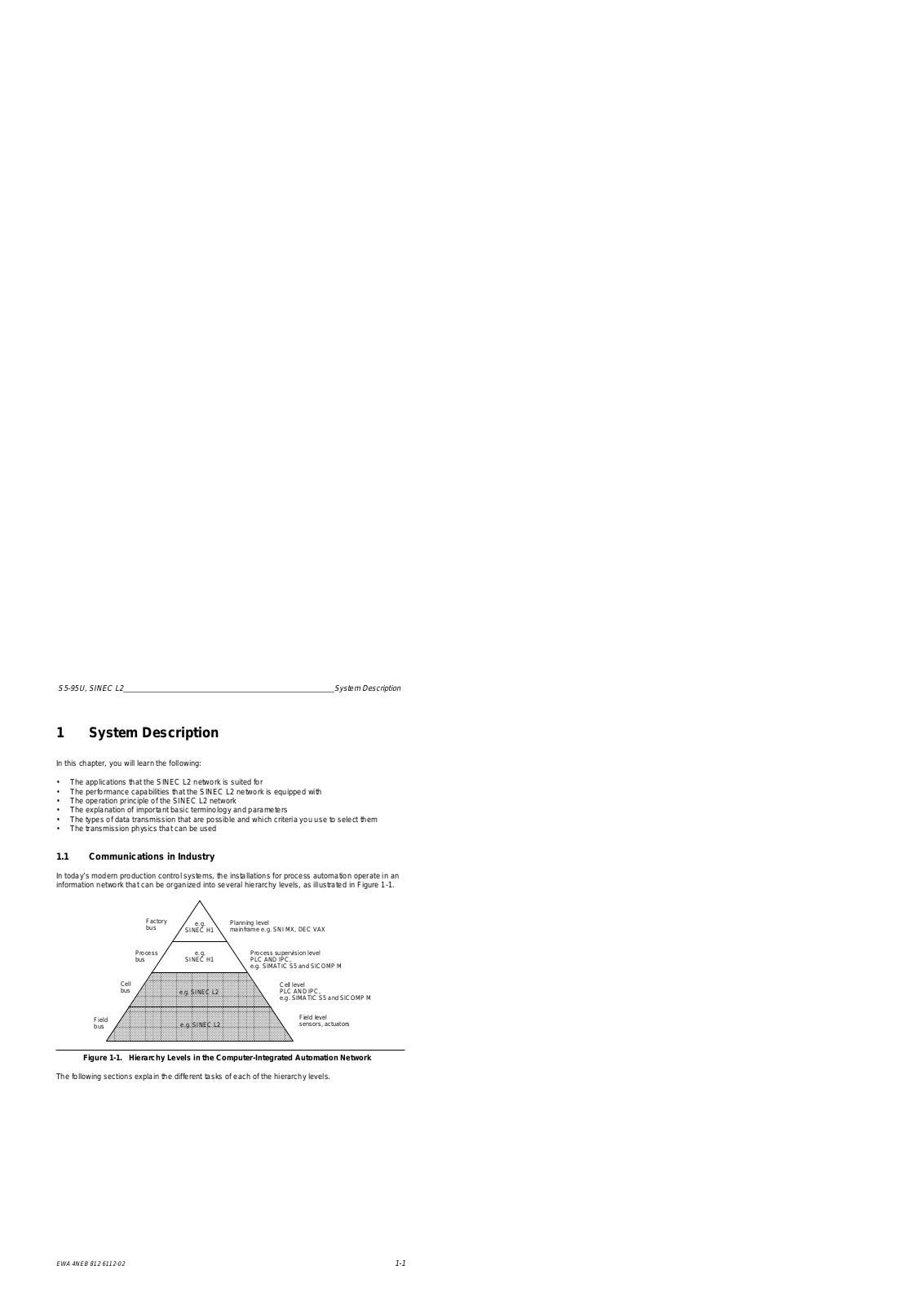


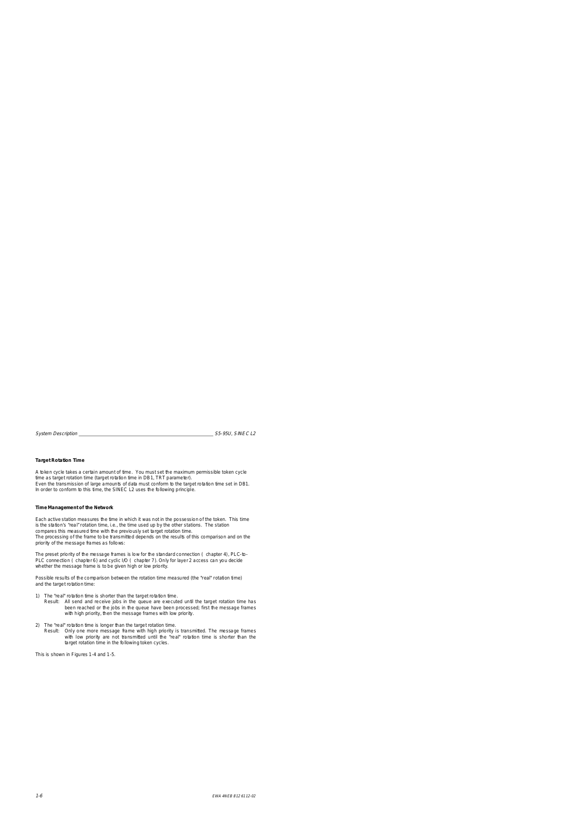
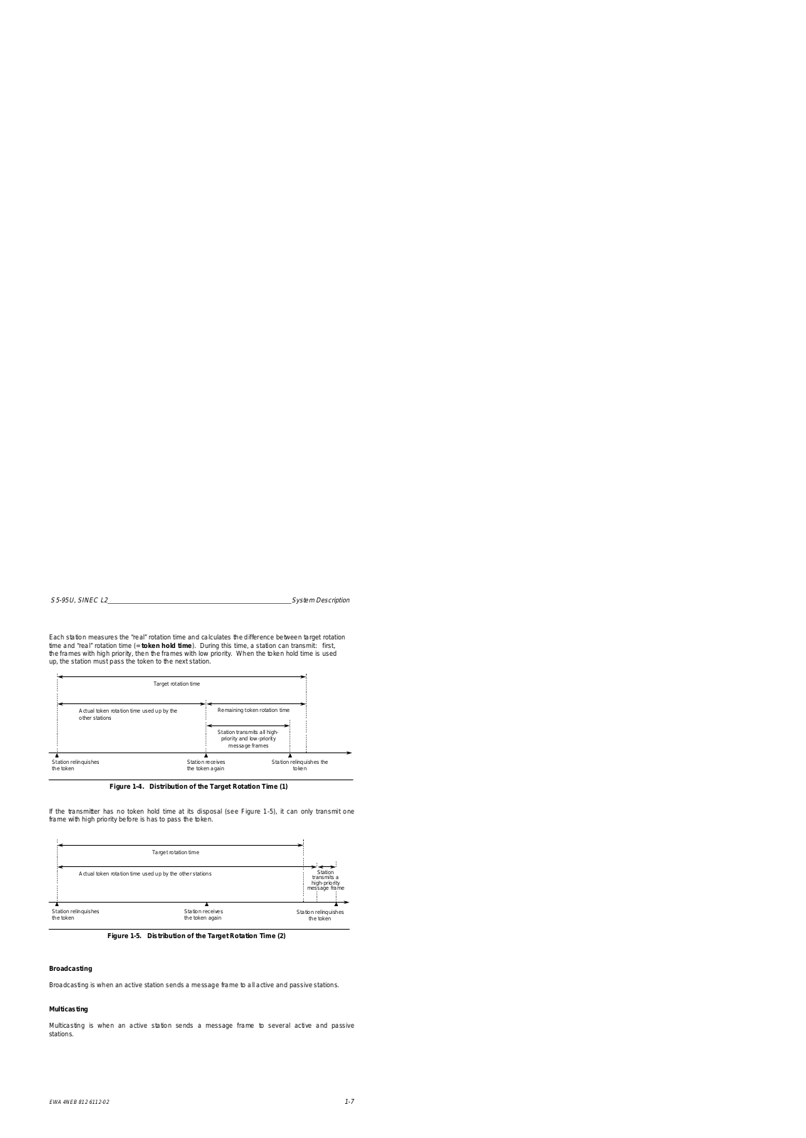
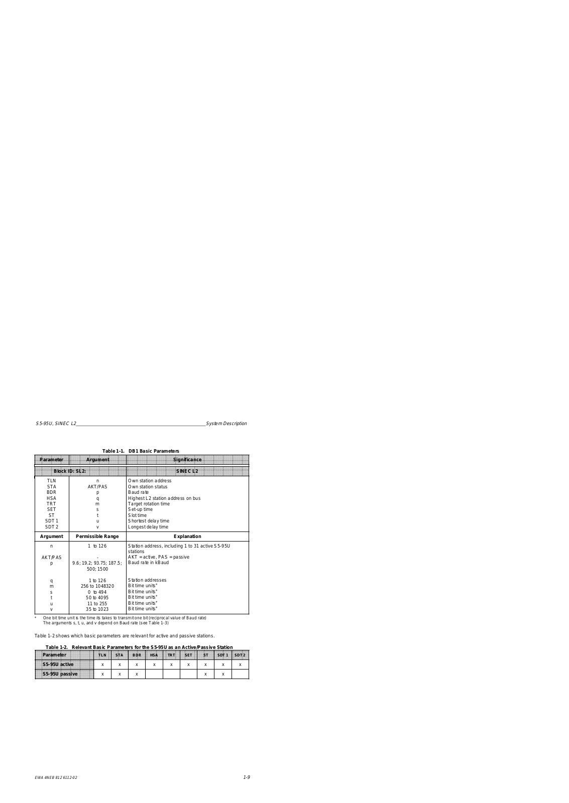
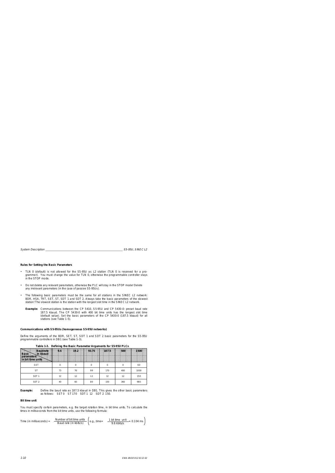
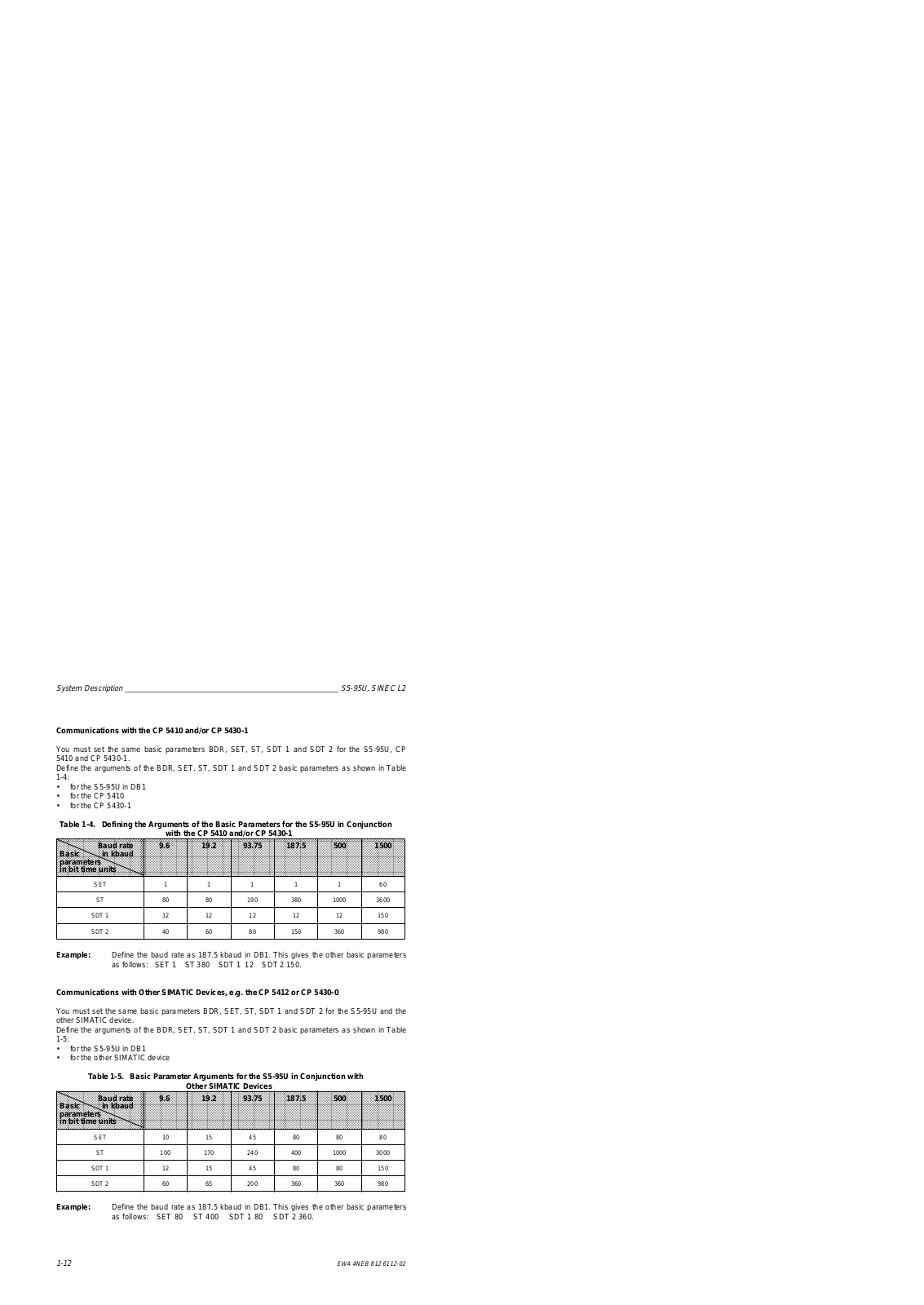
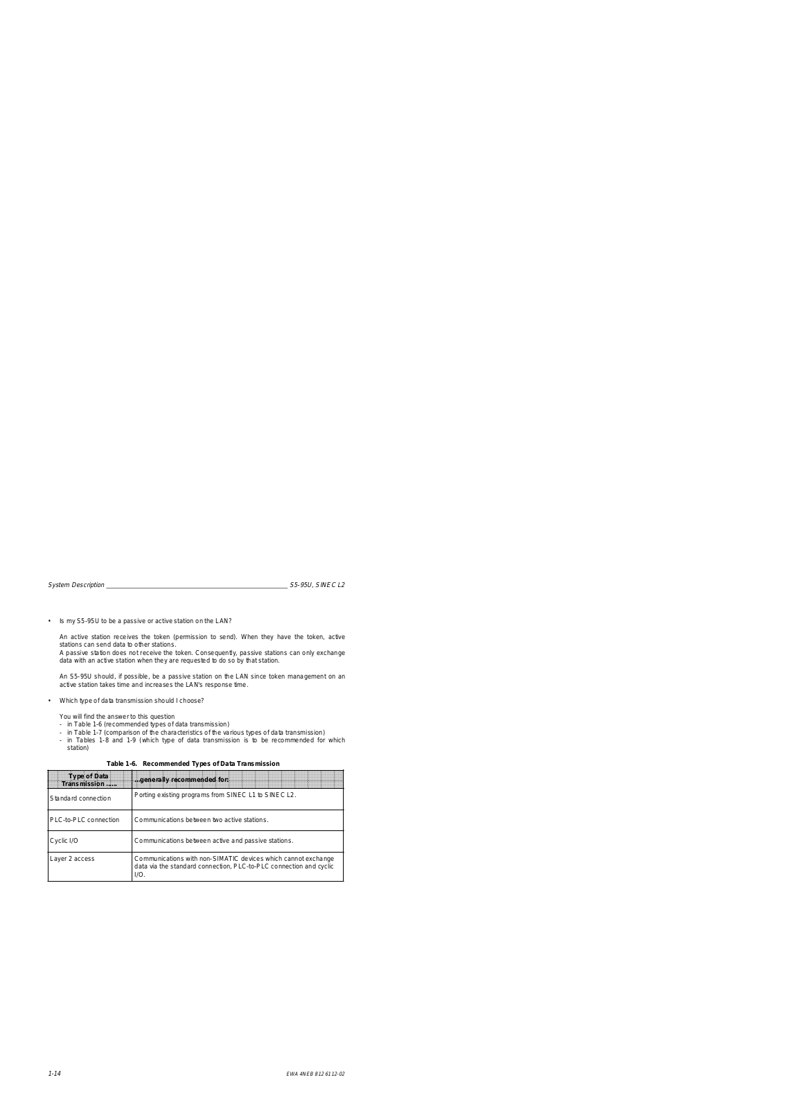
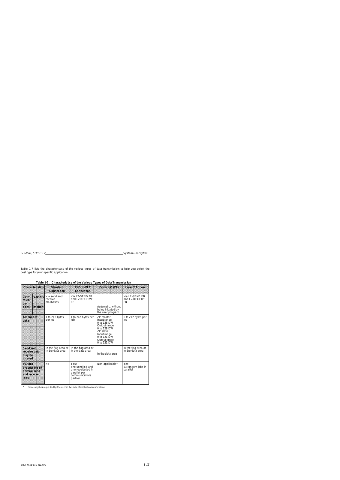

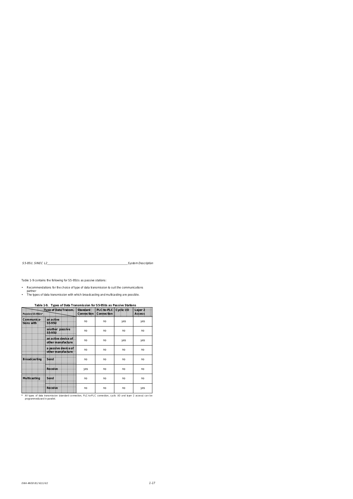
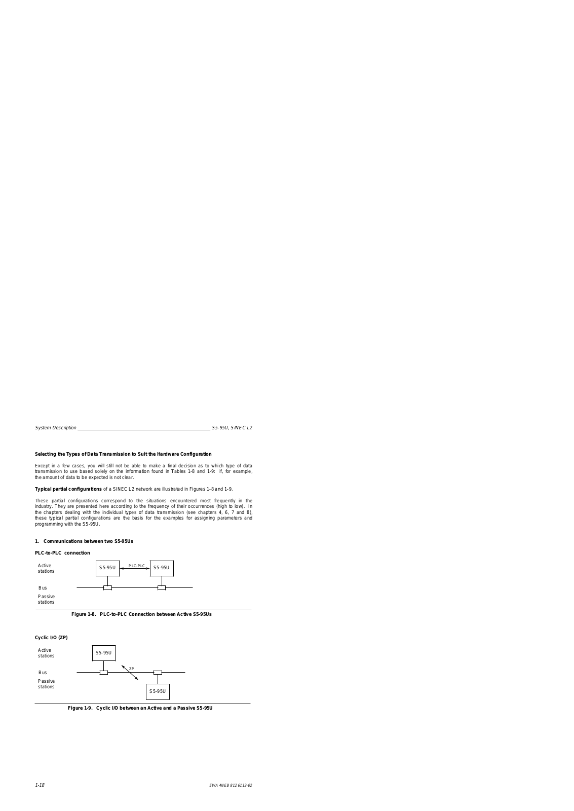


 Loading...