

Siemens SINAUT MD741-1 System Manual
SIMATIC NET
EGPRS/GPRS-Router
SINAUT MD741-1
System manual
Preface, Contents
Applications and functions
1
Setup
2
Configuration
3
Local interface
4
External interface
5
Security functions
6
Remote access
7
Status, log and diagnosis
8
Additional functions
9
Technical Data
10
Applied Standards and
Approvals
11
Glossary
C79000-G8976-C212
Release 4/2008
SINAUT MD741-1
2 C79000- G8976-C212
Safety Guidelines
This manual contains notices you have to observe in order to ensure your personal safety, as well as to prevent
damage to property. The notices referring to your personal safety are highlighted in the manual by a safety alert
symbol, notices referring only to property damage have no safety alert symbol. These notices shown below are
graded according to the degree of danger.
!
Danger
indicates that death or severe personal injury will result if proper precautions are not taken
!
Warning
indicates that death or severe personal injury may result if proper precautions are not taken.
!
Caution
with a safety alert symbol, indicates that minor personal injury can result if proper precautions are not taken..
Caution
without a safety alert symbol, indicates that property damage can result if proper precautions are not taken.
Notice
indicates that an unintended result or situation can occur if the corresponding information is not taken into
account.
If more than one degree of danger is present, the warning notice representing the highest degree of danger will
be used. A notice warning of injury to persons with a safety alert symbol may also include a warning relating to
property damage.
Qualified Personnel
The device/system may only be set up and used in conjunction with this documentation. Commissioning and
operation of a device/system may only be performed by qualified personnel. Within the context of the safety notes
in this documentation qualified persons are defined as persons who are authorized to commission, ground and
label devices, systems and circuits in accordance with established safety practices and standards.
Prescribed Usage
Note the following:
!
Warning
This device may only be used for the applications described in the catalog or the technical description and only in
connection with devices or components from other manufacturers which have been approved or recommended by
Siemens. Correct, reliable operation of the product requires proper transport, storage, positioning and assembly
as well as careful operation and maintenance
Trademarks
All names identified by ® are registered trademarks of the Siemens AG. The remaining trademarks in this
publication may be trademarks whose use by third parties for their own purposes could violate the rights of the
owner.
Disclaimer of Liability
We have reviewed the contents of this publication to ensure consistency with the hardware and software
described. Since variance cannot be precluded entirely, we cannot guarantee full consistency. However, the
information in this publication is reviewed regularly and any necessary corrections are included in subsequent
editions.
Siemens AG
Automation and Drives
Postfach 48 48
90437 NÜRNBERG
GERMANY
Order No.: C79000-G8976-C212
Release 04/2008
Copyright © Siemens AG 2008
Technical data subject to change

SINAUT MD741-1
C79000- G8976-C212
3
General
The product MD741-1 complies with European standard EN60950, 05.2003, Safety
of Information Technology Equipment.
Read the installation instructions carefully before using the device.
Keep the device away from children, especially small children.
The device must not be installed or operated outdoors or at damp locations.
Do not operate the device if the connecting leads or the device itself are damaged.
External power supply
Use only an external power supply which also complies with EN60950. The output
voltage of the external power supply must not exceed 30V DC. The output of the
external power supply must be short-circuit proof.
!
Warning
The power supply unit to supply the SINAUT MD741-1 must comply with the
requirements for a Limited Power Source according to IEC/EN 60950-1
The power supply unit to supply the SINAUT MD741-1 must comply with NEC Class 2
circuits as outlined in the National Electrical Code ® (ANSI/NFPA 70) only.
Please pay regard to section 2.6 of the system manual, as well as the installation
and utilisation regulations of the respective manufacturers of the power supply, the
battery or the accumulator.
SIM card
To install the SIM card the device must be opened. Before opening the device,
disconnect it from the supply voltage. Static charges can damage the device when
it is open. Discharge the electric static of your body before opening the device. To
do so, touch an earthed surface, e.g. the metal casing of the switch cabinet. Please
pay regard to section 2.6 of this system manual.
Handling cables
Never pull a cable connector out of a socket by its cable, but pull on the connector
itself. Cable connectors with screw fasteners (D-Sub) must always be screwed on
tightly. Do not lay the cable over sharp corners and edges without edge protection.
If necessary, provide sufficient strain relief for the cables.
For safety reasons, make sure that the bending radius of the cables is observed.
SINAUT MD741-1
4 C79000- G8976-C212
Failure to observe the bending radius of the antenna cable results in the
deterioration of the system's transmission and reception properties. The minimum
bending radius static must not fall below 5 times the cable diameter and dynamic
below 15 times the cable diameter.
Radio device
!
Warning
Never use the device in places where the operation of radio devices is prohibited. The
device contains a radio transmitter which could in certain circumstances impair the
functionality of electronic medical devices such as hearing aids or pacemakers. You
can obtain advice from your physician or the manufacturer of such devices. To prevent
data carriers from being demagnetised, do not keep disks, credit cards or other
magnetic data carriers near the device.
Installing antennas
!
Warning
The emission limits as recommended by the German Commission on Radiological
Protection (13/14 September 2001; www.ssk.de) must be observed.
Installing an external antenna
Caution
When installing an antenna outdoors it is essential that the antenna is fitted correctly
by a qualified person.
When the antenna is installed outdoors it must be earthed for lightning protection. The
outdoor antennas shield must be reliable connective to protective earth.
The installation shall be done according the national installation codes
For US this is the National Electric Code NFPA 70, article 810.
For Germany, observe the current version of the Lightning Protection Standard VDE
0185 (DIN EN 62305) Sections 1 to 4 for buildings with lightning protection, or the
standard VDE 0855 (DIN EN 60728-11) in case there is no lightning protection.
This work must be carried out by qualified personnel only.

SINAUT MD741-1
C79000- G8976-C212
5
Requirements for compliance to Safety, Telecom, EMC and other standards
Caution
Observe the regulations listed in chapter 12 before putting the SINAUT MD741-1 into
operation.
Operating costs
Caution: GPRS costs
Note that data packets exchanged for setting up connections, reconnecting, connect
attempts (e.g. Server switched off, wrong destination address, etc.) as well as keeping
the connection alive are also subject to charge.

SINAUT MD741-1
6 C79000- G8976-C212
Firmware with Open Source GPL/LGPL
The firmware of the SINAUT MD741-1 includes open Source Software under terms
of GPL/LGPL. According to section 3b of GPL and of section 6b of LGPL we
provide you the source code. Please write to
s_opsource@gmx.net
s_opsource@gmx.de
Please enter 'Open Source MD741' as subject of your e-mail, that we can filter your
e-mail easier.
Firmware with OpenBSD
The firmware of SINAUT MD741-1 contains sections from the OpenBSD software.
The use of OpenBSD software is subject to the following copyright notice
* Copyright (c) 1982, 1986, 1990, 1991, 1993
* The Regents of the University of California. All rights reserved.
*
* Redistribution and use in source and binary forms, with or without
* modification, are permitted provided that the following conditions
* are met:
* 1. Redistributions of source code must retain the above copyright
* notice, this list of conditions and the following disclaimer.
* 2. Redistributions in binary form must reproduce the above copyright
* notice, this list of conditions and the following disclaimer in the
* documentation and/or other materials provided with the distribution.
* 3. All advertising materials mentioning features or use of this software
* must display the following acknowledgement:
* This product includes software developed by the University of
* California, Berkeley and its contributors.
* 4. Neither the name of the University nor the names of its contributors
* may be used to endorse or promote products derived from this software
* without specific prior written permission.
*
* THIS SOFTWARE IS PROVIDED BY THE REGENTS AND CONTRIBUTORS ``AS IS'' AND
* ANY EXPRESS OR IMPLIED WARRANTIES, INCLUDING, BUT NOT LIMITED TO, THE
* IMPLIED WARRANTIES OF MERCHANTABILITY AND FITNESS FOR A PARTICULAR
* PURPOSE
* ARE DISCLAIMED. IN NO EVENT SHALL THE REGENTS OR CONTRIBUTORS BE LIABLE
* FOR ANY DIRECT, INDIRECT, INCIDENTAL, SPECIAL, EXEMPLARY, OR
* CONSEQUENTIAL
* DAMAGES (INCLUDING, BUT NOT LIMITED TO, PROCUREMENT OF SUBSTITUTE GOODS
* OR SERVICES; LOSS OF USE, DATA, OR PROFITS; OR BUSINESS INTERRUPTION)
* HOWEVER CAUSED AND ON ANY THEORY OF LIABILITY,
* WHETHER IN CONTRACT, STRICT
* LIABILITY, OR TORT (INCLUDING NEGLIGENCE OR OTHERWISE) ARISING IN ANY WAY
* OUT OF THE USE OF THIS SOFTWARE, EVEN IF ADVISED OF THE POSSIBILITY OF
* SUCH DAMAGE.

SINAUT MD741-1
C79000- G8976-C212
7
Preface
Purpose of this documentation
This documentation will support you on your way to successful application of
GSM/GPRS modem SINAUT MD741-1. It will introduce you to the topic in
clear and straightforward steps and provide you with an overview of the
hardware of the SINAUT MD741-1 GSM/GPRS modem. This documentation
will help you during installation and commissioning of SINAUT GSM/GPRS
modem and explains the diagnostics and service options available.
Validity of the documentation
This manual relates to the following product versions
• GPRS/GSM modem MD741-1 hardware release 2.x
SIMATIC Technical Support
You can contact Technical Support for all A&D products
• Phone: +49 (0) 180 5050 222
• Fax: +49 (0) 180 5050 223
You will find further information on our Technical Support on the Web at
http://www.siemens.com/automation/service
Service & Support on the Internet
In addition to our documentation services, you can also make use of all our
knowledge on the Internet:
http://www.siemens.com/automation/service&support
Here, you will find:
• Up-to-date product information (Updates), FAQs (Frequently Asked
Questions), Downloads, Tips and Tricks.
• The Newsletter keeps you constantly up to date with the latest
information on the products you use.
• The Knowledge Manager will find the documents you need.
• In the Forum, users and specialists exchange information and
experience.
• You can find your local contact for Industry Automation in our contacts
database.
• You will find information on local service, repairs, spares and much more
under the rubric "Service".

SINAUT MD741-1
8 C79000- G8976-C212
You will find the latest version of this documentation under the entry ID
22550242.
Do you still have questions relating to the use of the products described in
the manual? If so, then please talk to your local Siemens contact.
You will find the addresses in the following sources:
• On the Internet at: http://www.siemens.com/automation/partner
• On the Internet at http://www.siemens.com/simatic-net specifically for
SIMATIC NET products
• In the catalog CA 01
• In the catalog IK PI specifically for SIMATIC NET products
Statements, certificates and other useful information about SINAUT
MD741-1 are available at:
• http://support.automation.siemens.com/WW/view/de/22811843
SIMATIC training center
To familiarize you with the systems and products, we offer a range of
courses. Please contact your regional training center or the central training
center in
D-90327 Nuernberg.
Phone: +49 (911) 895-3200
http://www.sitrain.com
SIMATIC NET training center
For courses specifically on products from SIMATIC NET, please contact:
SIEMENS AG
Siemens AG, A&D Informations- und Trainings-Center
Dynamostr. 4
D-68165 Mannheim
Phone: +49 (621) 4 56-23 77
Fax: +49 (621) 4 56-32 68

SINAUT MD741-1
C79000- G8976-C212
9
Contents
1 Applications and functions ......................................................................................... 11
2 Setup.............................................................................................................................. 15
2.1 Step by step....................................................................................................... 15
2.2 Preconditions for operation................................................................................ 16
2.3 Device front........................................................................................................ 17
2.4 Service button (SET) ......................................................................................... 17
2.5 Operating state indicators.................................................................................. 18
2.6 Connections....................................................................................................... 19
2.7 Inserting the SIM card........................................................................................ 21
2.8 Top rail mounting ............................................................................................... 22
3 Configuration................................................................................................................23
3.1 TCP/IP configuration of the network adapter in Windows XP ........................... 24
3.2 Establishing a configuration connection ............................................................ 25
3.3 Start page of the Web user interface................................................................. 28
3.4 Language selection............................................................................................ 31
3.5 Configuration procedure .................................................................................... 32
3.6 Configuration Profiles ........................................................................................ 33
3.7 Changing the password ..................................................................................... 34
3.8 Reboot ............................................................................................................... 35
3.9 Load factory settings.......................................................................................... 37
4 Local interface .............................................................................................................. 39
4.1 IP addresses of the local interface .................................................................... 39
4.2 DHCP server to local network ........................................................................... 41
4.3 DNS to local network ......................................................................................... 43
4.4 Local hostname ................................................................................................. 45
4.5 System Time/NTP.............................................................................................. 46
4.6 Additional Internal Routes ................................................................................. 48
5 External interface ......................................................................................................... 49
5.1 Access parameters to EGPRS/GPRS ............................................................... 49
5.2 EGPRS/GPRS Connection Monitoring.............................................................. 51
5.3 Hostname via DynDNS...................................................................................... 53
6 Security functions........................................................................................................ 57
6.1 Packet Filter....................................................................................................... 57
6.2 Port Forwarding ................................................................................................. 62
6.3 Advanced security functions.............................................................................. 64
6.4 Firewall Log ....................................................................................................... 66
7 VPN connection............................................................................................................ 67

Contents
SINAUT MD741-1
10 C79000- G8976-C212
7.1 VPN Roadwarrior Mode..................................................................................... 69
7.2 VPN IPsec Standard Mode................................................................................ 76
7.3 Loading VPN certificates ................................................................................... 85
7.4 Firewall rules for VPN tunnel ............................................................................. 87
7.5 Advanced settings for VPN connections ........................................................... 88
7.6 Status of the VPN connections.......................................................................... 90
8 Remote access ............................................................................................................. 91
8.1 HTTPS remote access....................................................................................... 91
8.2 SSH remote access ........................................................................................... 93
8.3 Remote access via dial-in connection ............................................................... 95
9 Status, log and diagnosis............................................................................................ 99
9.1 System status display ........................................................................................ 99
9.2 Log................................................................................................................... 103
9.3 Remote logging................................................................................................ 105
9.4 Snapshot.......................................................................................................... 107
9.5 Hardware information ...................................................................................... 109
9.6 Software information........................................................................................ 110
10 Additional functions................................................................................................... 111
10.1 Alarm SMS....................................................................................................... 111
10.2 Software Update .............................................................................................. 112
11 Technical Data ............................................................................................................ 115
12 Applied Standards and Approvals............................................................................ 119
12.1 Equipment........................................................................................................ 119
12.2 EU Declaration of Conformance...................................................................... 119
12.3 Compliance to FM, UL and CSA ..................................................................... 121
12.4 Compliance to FCC ......................................................................................... 122
Glossary...................................................................................................................... 125

SINAUT MD741-1
C79000- G8976-C212
11
Applications and functions
1
The SINAUT MD741-1 provides a wireless connection to the Internet or to a private
network. The SINAUT MD741-1 can provide this connection in any location where
a GSM network (Global System for Mobile Communication = mobile phone
network) is available which provides the services EGPRS (Enhanced General
Packet Radio Service = EDGE) or GPRS (General Packet Radio Service). A
precondition for this is a SIM card of a GSM network operator with the appropriate
services activated.
The SINAUT MD741-1 thus links a locally connected application or entire networks
to the Internet via wireless IP connections. It is also possible to connect directly to
an intranet, to which in turn the external remote stations are connected.
The SINAUT MD741-1 can establish a VPN (Virtual Private Network) between a
locally connected application / a network and an external network, and can protect
this connection against access by third parties through the use of IPsec (Internet
Protocol Security).
In order to perform these tasks in the scenarios described, the device combines the
following functions:
• EDGE modem for flexible data communication via EGPRS or GPRS
• Firewall for protection against unauthorized access. The dynamic packet filter
examines data packets based on their source and destination addresses
(stateful inspection firewall) and blocks undesirable data traffic (anti-spoofing)
• The SINAUT MD741-1 can establish via the wireless IP connections a VPN
Virtual Private Network) between the locally connected application or network
and en external network and can protect this connection by IPsec (Internet
Protocol Security) against unwanted access by third parties.
Applications and functions
SINAUT MD741-1
12 C79000- G8976-C212
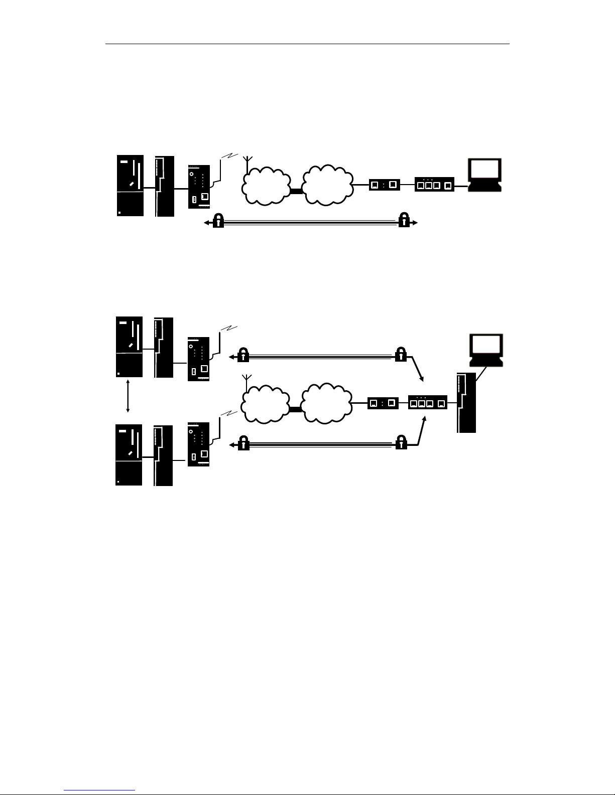
Application examples of the SINAUT MD741-1
APN
(E-)GPRS
INTERNET
MD741-1
DSL-Modem
TIM
CPU
VPN-Router
Central
Station
ST7cc
VPN-Tunnel
S7-300
Figure 1-1 Connection between CPU and Central Station
APN
(E-)GPRS
INTERNET
MD741-1
DSL-Modem
VPN-Router
Central
Station
ST7cc
MD741-1
VPN-Tunnel
VPN-Tunnel
TIM
Logical
connection
TIM
CPU
TIM
CPU
Figure 1-2 Connection between two CPU
Configuration
The device can be configured via a Web user interface that can simply be
displayed using a Web browser. It can be accessed by means of the following:
• the local interface
• EGPRS/GPRS
• CSD (Circuit Switched Data = dial-in data connection) of the GSM
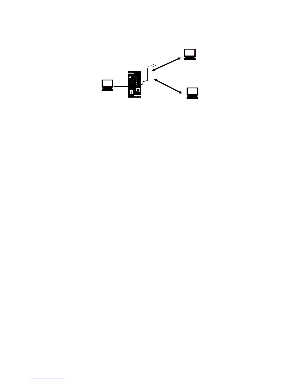
Applications and functions
SINAUT MD741-1
C79000- G8976-C212
13
MD741-1
Connection
via (E-)GPRS
PC with
Web browser
Connection via
GSM-CSD
PC with
Web browser
PC with
Web browser
Figure 1-3 Configuration
Firewall functions
The SINAUT MD741-1 provides the following firewall functions in order to protect
the local network and itself from external attacks:
● Stateful inspection firewall
● Anti-spoofing
● Port forwarding
● NAT
Additional functions
The SINAUT MD741-1 provides the following additional functions:
● DNS cache
● DHCP server
● NTP
● Remote logging
● In Port
● Web user interface for configuration
● Sending alarm SMS
● SSH console for configuration
● DynDNS client
● Dial-in data connection for maintenance and remote configuration

Applications and functions
SINAUT MD741-1
14 C79000- G8976-C212

SINAUT MD741-1
C79000- G8976-C212
15
Setup
2
2.1 Step by step
Set up the SINAUT MD741-1 in the following steps:
Step
Chapter
1.
First familiarise yourself with the preconditions for operation
of the SINAUT MD741-1.
2.2
2.
Read the safety instructions and other instructions at the
beginning of this document very carefully, and be sure to
follow them.
3.
Familiarise yourself with the control elements, connections
and operating state indicators of the SINAUT MD741-1.
2.4 -2.6
4.
Connect a PC with a Web browser (Admin PC) to the local
interface (X2) of the SINAUT MD741-1.
3
5.
Using the Web user interface of the SINAUT MD741-1, enter
the PIN (Personal Identification Number) of the SIM card.
5.1
6.
Disconnect the SINAUT MD741-1 from the power supply.
2.6
7.
Insert the SIM card in the device.
2.7
8.
Connect the antenna.
2.6
9.
Connect the SINAUT MD741-1 to the power supply.
2.6
10.
Set the SINAUT MD741-1 up in accordance with your
requirements.
3 - 10
11.
Connect your local application.
2.6

Setup
SINAUT MD741-1
16 C79000- G8976-C212
2.2 Preconditions for operation
In order to operate the SINAUT MD741-1, the following information must be on
hand and the following preconditions must be fulfilled:
Antenna
An antenna, adapted to the frequency bands of the GSM network operator you
have chosen: 850 MHz, 900 MHz, 1800 MHz or 1900 MHz. Use only antennas
from the accessories for the SINAUT MD741-1.
See Chapter 2.6.
Power supply
A power supply with a voltage between 12 VDC and 30 VDC that can provide
sufficient current.
See Chapter 2.6.
SIM card
A SIM card from the chosen GSM network operator.
PIN
The PIN for the SIM card.
EGPRS / GPRS activation
The SIM card must be activated by your GSM network operator for the services
EGPRS or GPRS.
The EGPRS / GPRS access data must be known:
● Access Point Name (APN)
● User name
● Password
CSD 9600 bit/s activation
The SIM card must be activated by your GSM network operator for the CSD
service if you wish to use remote configuration via a dial-in data connection, see
Chapter 8.3.
Setup
SINAUT MD741-1
C79000- G8976-C212
17
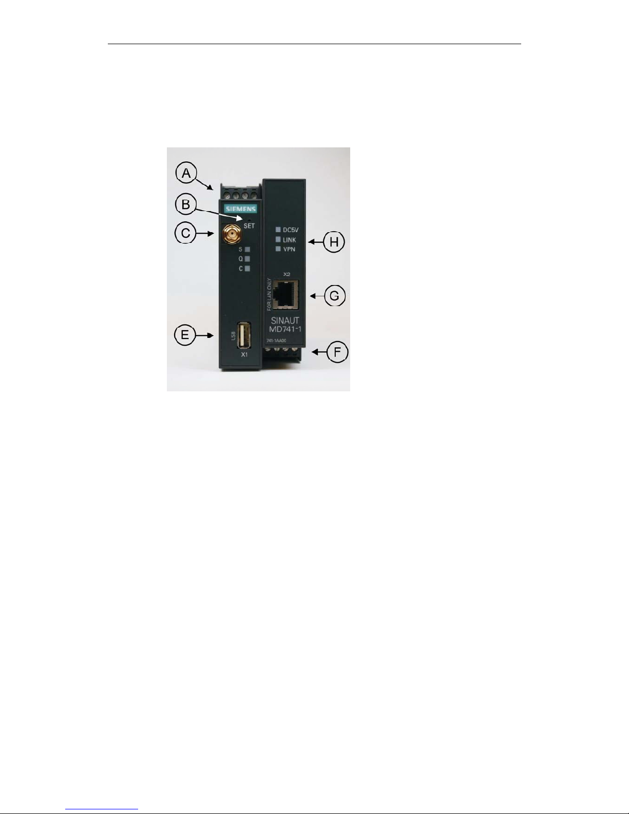
2.3 Device front
Here are definitions of terms frequently used in this manual:
A – Connection terminals for the
power supply
B – Set button
C – Antenna jack type SMA
D – Operating state indicators S,
Q,
E – X1 (Service; USB) – without
function
F – Connection terminals for the
gate inputs and outputs
G – 10/100 Base-T - RJ45 jack for
connecting the local network
H – Operating state indicators
Power, LAN, VPN
Figure 2-1 Operating elements
2.4 Service button (SET)
On the front side of the SINAUT MD741-1 there is a small hole (see B) which is
SET marked and has a button behind it. Use a pointed object, e.g. a straightenedout paperclip, to press this button.
● If you press the button for longer than 5 seconds, the SINAUT MD741-1
reboots and loads the factory settings.

Setup
SINAUT MD741-1
18 C79000- G8976-C212
2.5 Operating state indicators
The SINAUT MD741-1 has 7 indicator lamps (LEDs) to indicate the operating state.
The 3 indicator lamps on the left-hand side of the device indicate the state of the
EGPRS wireless modem:
LED State Meaning
Flashing slowly PIN transfer
Flashing quickly PIN error / SIM error
S (Status)
ON PIN transfer successful
OFF Not logged into GSM network
Flashing briefly
Poor signal strength
(CSQ < 6)
Flashing slowly
Medium signal strength
(CSQ= 6..10)
ON, with brief interruptions
Good signal strength
(CSQ=11-18)
Q
(Quality)
ON
Very good signal strength
(CSQ > 18)
OFF No connection
Flashing quickly Service call via CSD active
ON with brief interruptions GPRS connection active
C
(Connect)
ON EGPRS connection active
Light up in sequence quickly Booting
Light up in sequence slowly Update
S, Q, C
together
Flashing quickly in unison Error
The 3 indicator lamps on the right-hand side of the device indicate the state of
additional device functions:
LED State Meaning
ON
Device switched on, operating
voltage present
DC5V
OFF
Device switched off, operating
voltage not present
ON
Ethernet connection established to the
local application / the local network
OFF
No Ethernet connection to the local
application / the local network
LINK
ON with brief interruptions
Data transfer via the Ethernet
connection
ON VPN connection active
VPN
OFF VPN connection active

Setup
SINAUT MD741-1
C79000- G8976-C212
19
2.6 Connections
X2 (10/100 Base-T)
The local network is connected to the local applications at the 10/100 Base-T
connection, e.g. a programmable controller, a machine with an Ethernet interface
for remote monitoring, or a notebook or desktop PC.
To set up the SINAUT MD741-1, connect the Admin PC with Web browser here.
The interface supports autonegation. It is thus detected automatically whether a
transmission speed of 10 Mbit/s or 100 Mbit/s is used on the Ethernet.
A connecting cable with a RJ45 plug must be used. It can be a cross-over cable or
a patch cable.
X1 (USB; Service)
In the SINAUT MD741-1 this interface has no function and is reserved for later
applications. Do not connect any devices here. Doing so could interfere with the
SINAUT MD741-1's operation.
SMA antenna jack
The SINAUT MD741-1 has an antenna jack of the type SMA for connecting the
antenna.
The antenna that is used should have an impedance of about 50 ohms. It must be
matched for GSM 900MHz and DCS 1800MHz or GSM 850 MHz and PCS 1900
MHz, depending on which frequency bands your GSM network operator uses. In
Europe and China GSM 900MHz and DCS 1800MHz are used, in the USA GSM
850 MHz and PCS 1900 MHz are used. Obtain this information from your network
operator.
The match (VSWR) of the antenna must be 1:2.5 or better.
Caution:
Use only antennas from the accessories line for the SINAUT MD741-1. Other
antennas could interfere with product characteristics or even lead to defects.
When installing the antenna, a sufficiently good signal quality must be ensured
(CSQ > 11). Use the indicator lamps of the SINAUT MD741-1 which show the
signal quality. Make sure that there are no large metal objects (e.g. reinforced
concrete) close to the antenna.
Observe the installation and user instructions for the antenna being used.
Setup
SINAUT MD741-1
20 C79000- G8976-C212
Warning:
When the antenna is installed outdoors it must be earthed for lightning protection.
The outdoor antennas shield must be reliable connective to protective earth. The
installation shall be done according the national installation codes (For US this is
the National Electric Code NFPA 70, article 810).
This work must be carried out by qualified personnel only.
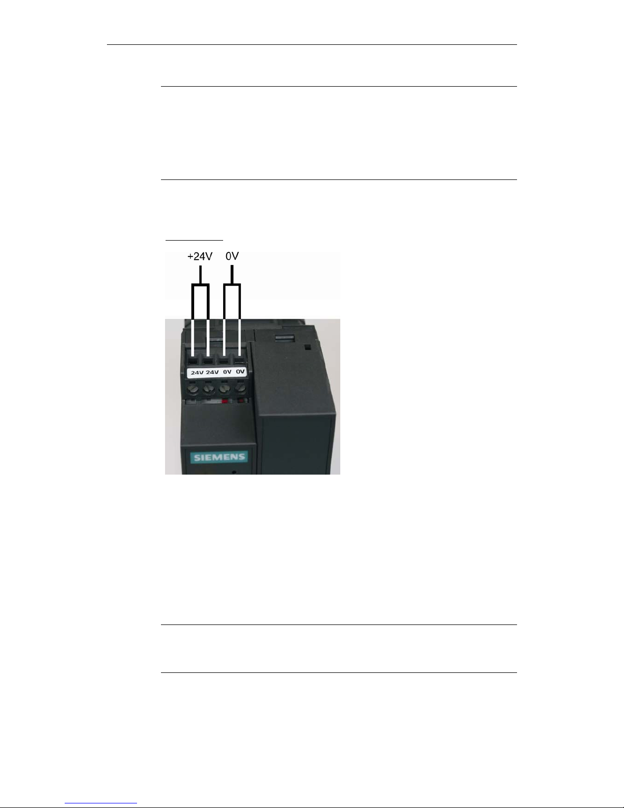
Screw terminals power supply (24V / 0V)
Power supply
Figure 2-2 Screw terminals
The SINAUT MD741-1 operates with direct current of from 12-30 V DC, nominally
24 V DC. This power supply is connected at the screw terminals on the left-hand
side of the device.
Connect the positive supply voltage to one or both screw terminals marked 24V
and the negative supply voltage to one or both screw terminals marked 0V.
The rated current consumption is about 510mA at 12V and 230mA at 30V.
Warning:
The power supply unit of the SINAUT MD741-1 is not galvanic isolated. Observe
the safety instructions at the beginning of this manual.
Setup
SINAUT MD741-1
C79000- G8976-C212
21
Field wiring instruction
Use copper wires only.
Solid wire: 0,5...3mm
2
(AWG 20...18)
Strained wire: 0,5...2,5mm
2
Torque of screw clamps: 0,6...0,8Nm
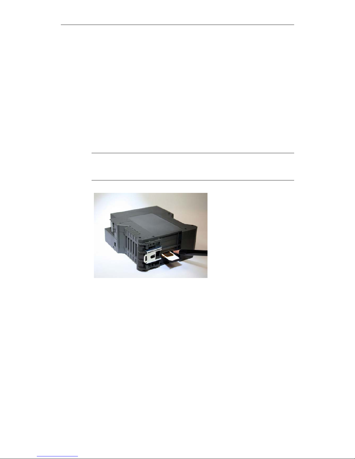
2.7 Inserting the SIM card
Caution:
Before inserting the SIM card, enter the PIN of the SIM card in the SINAUT
MD741-1 via the Web user interface. See Chapter 5.1.
Figure 2-3 Inserting the SIM card
1. After you have entered the PIN of the SIM card, disconnect the SINAUT
MD741-1 completely from the power supply.
2. The drawer for the SIM card is located on the back of the device. Right next to
the drawer for the SIM card in the housing aperture there is a small yellow
button. Press on this button with a pointed object, for example a pencil.
When the button is pressed the SIM card drawer comes out of the housing.
3. Place the SIM card in the drawer so that its gold-plated contacts remain visible.
4. Then push the drawer with the SIM card completely into the housing.
Setup
SINAUT MD741-1
22 C79000- G8976-C212
Caution:
Do not under any circumstances insert or remove the SIM card during operation.
Doing so could damage the SIM card and the SINAUT MD741-1.
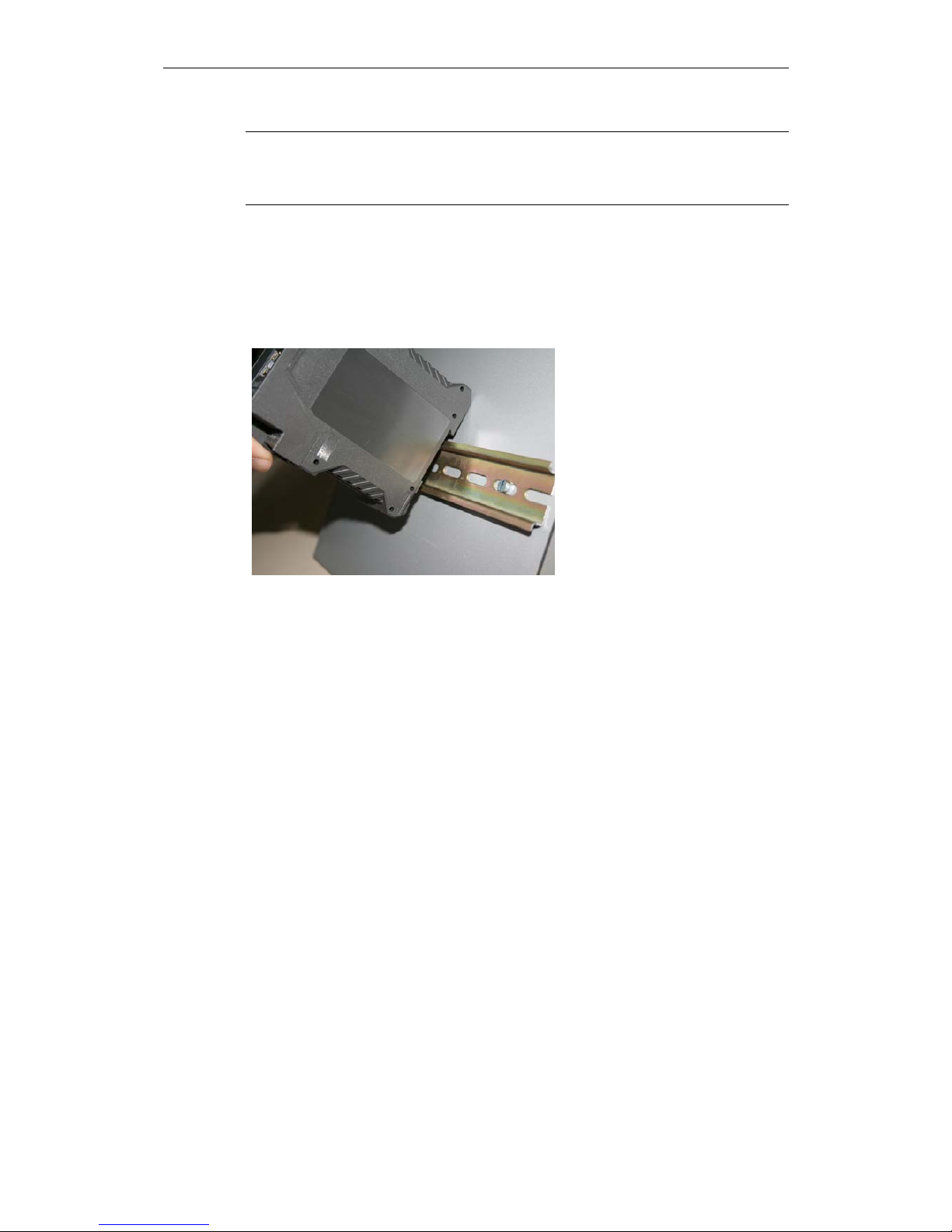
2.8 Top rail mounting
The SINAUT MD741-1 is suitable for top-hat rail mounting on DIN EN 50022 rails.
A corresponding bracket can be found at the rear of the device.
Figure 2-4 Top rail mounting

SINAUT MD741-1
23 C79000- G8976-C212
Configuration
3
Configuration of the router and firewall functions is carried out locally or remotely
via the Web-based administration interface of the SINAUT MD741-1.
Remote configuration
Remote configuration via HTTPS or CSD access is only possible if the SINAUT
MD741-1 is configured for remote access. In this case proceed exactly as
described in Chapter 8.
Configuration via the local interface
The preconditions for configuration via the local interface are:
● The computer (Admin PC) that you use to carry out configuration must be
either connected directly to the Ethernet jack of the SINAUT MD741-1 via a
network cable or it must have direct access to the SINAUT MD741-1 via the
local network.
● The network adapter of the computer (Admin PC) that you use to carry out
configuration must have the following TCP/IP configuration:
IP address: 192.168.1.2
Subnet mask: 255.255.255.0
Instead of the IP address 192.168.1.2 you can also use other IP addresses
from the range 192.169.1.x.
● If you also wish to use the Admin PC to access the external network via the
SINAUT MD741-1, the following additional settings are necessary:
Standard gateway: 192.168.1.1
Preferred DNS server: Address of the domain name server

Configuration
SINAUT MD741-1
24 C79000- G8976-C212
3.1 TCP/IP c onfiguration of the network adapter in Windows
XP
Configure the LAN connection
Click on Start, Connect To ..., Show All Connections…
Then click on LAN Connection. In the dialog box Properties of LAN Connection,
click on the General tab and select there the entry Internet Protocol (TCP/IP). Open
Properties by clicking on the corresponding button.
The window Properties of Internet Protocol (TCP/IP) appears (see illustration
below).
Note:
The path leading to the dialog box Properties of LAN Connection depends on your
Windows settings. If you are not able to find this dialog box, search in the Windows
Help function for LAN Connection or Properties of Internet Protocol (TCP/IP).
Figure 3-1 Properties of Windows Internet Protocol

Configuration
SINAUT MD741-1
C79000- G8976-C212
25
Enter the following values in order to get to the Web user interface of the SINAUT
MD741-1:
IP address: 192.168.1.2
Subnet mask: 255.255.255.0
In addition, enter the following values if you want to use the Admin PC to access
the external network via the SINAUT MD741-1:
Standard gateway: 192.168.1.1
Preferred DNS server: 192.168.1.1
Preferred DNS server
If you call up addresses via a domain name (e.g. www.neuhaus.de), then you must
refer to a domain name server (DNS) to find out what IP address is behind the
name. You can define the following as the domain name server:
● The DNS address of the network operator,
or
● The local IP address of the SINAUT MD741-1, as long as it is configured for
breaking out host names into IP addresses
(see Chapter 4.3; Factory setting).
To define the domain name server in the TCP/IP configuration of your network
adapter, proceed as described above.
3.2 Establishing a configuration connection
Setting up a Web browser
Proceed as follows:
1. Launch a Web browser.
(e.g. MS Internet Explorer Version 7 or later or Mozilla Firefox Version 2 or
later; the Web browser must support SSL (i.e. HTTPS).)
2. Make sure that the browser does not automatically dial a connection when it is
launched.
In MS Internet Explorer, make this setting as follows: Menu Tools, Internet
Options..., tab Connections: Under Dial-up and VPN Settings, make sure that
Never dial a connection is activated.
Configuration
SINAUT MD741-1
26 C79000- G8976-C212
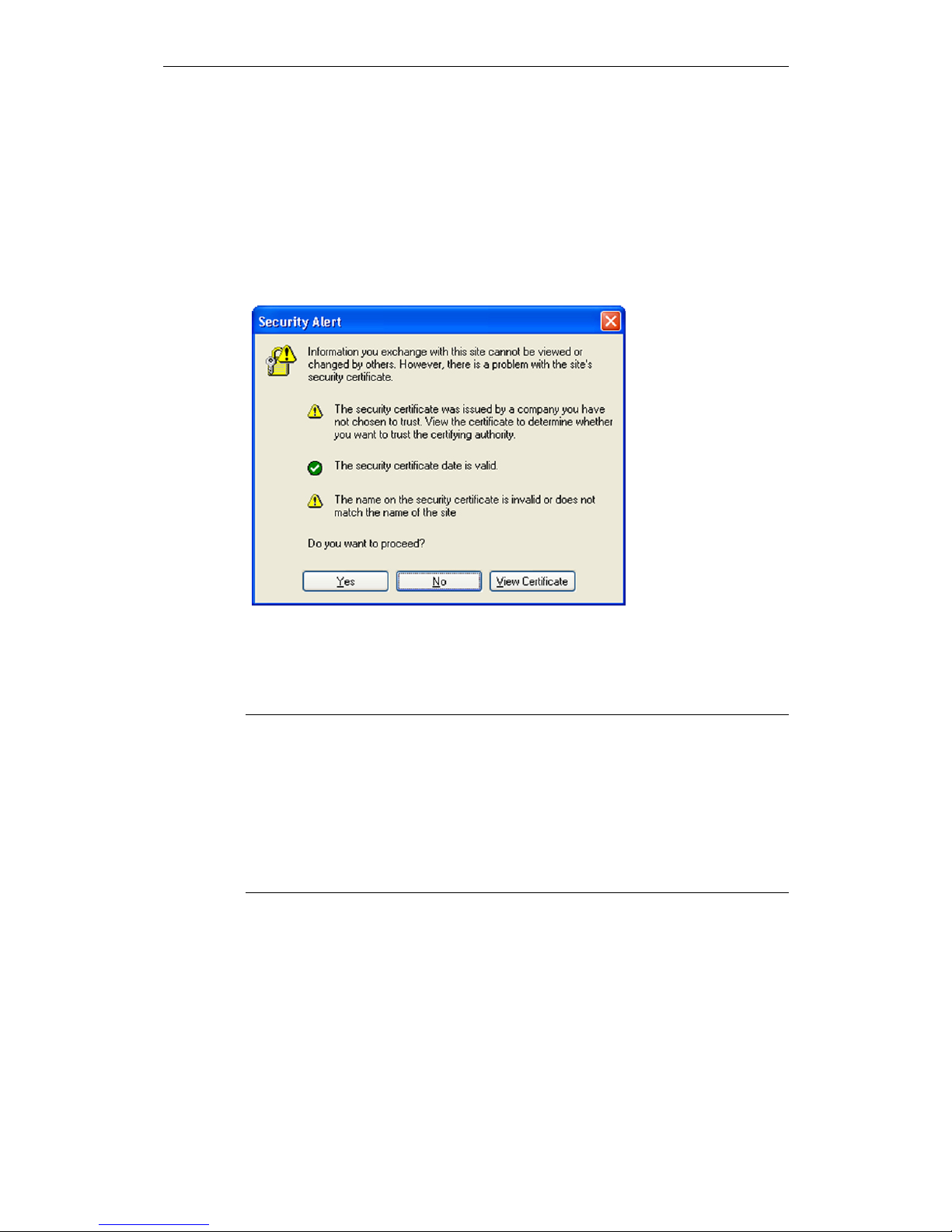
Calling up the start page of the SINAUT MD741-1
3. In the address line of the browser, enter the address of the SINAUT MD741-1
in full. In the factory settings this is:
https://192.168.1.1
Result: A security message appears. In Internet Explorer 7, for example, this
one:
Figure 3-2 Confirming the security message
4. Acknowledge the corresponding safety message with "Continue loading this
page …"
Note
Because the device can only be administered via encrypted access, it is delivered
with a self-signed certificate. In the case of certificates with signatures that the
operating system does not know, a security message is generated. You can
display the certificate.
It must be clear from the certificate that it was issued for SIEMENS AG. The Web
user interface is addressed via an IP address and not using a name, which is why
the name specified in the security certificate, is not the same as the one in the
certificate.
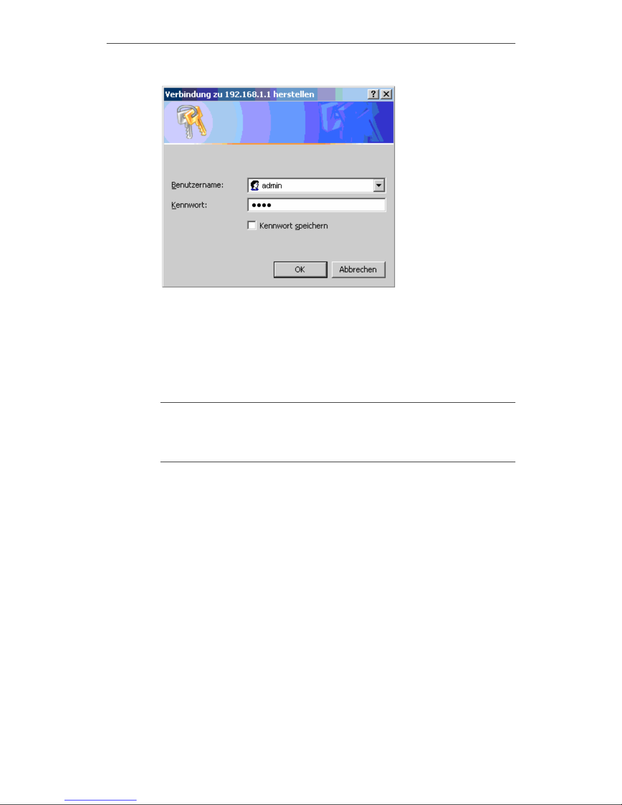
Entering the user name and password
5. You will be asked to enter the user name and the password:
Configuration
SINAUT MD741-1
C79000- G8976-C212
27
Figure 3-3 Enter user name and password
The factory setting is:
User name: admin
Password: sinaut
Note
You should change the password in any event. The factory setting is general
knowledge and does not provide sufficient protection. Chapter 3.7 contains a
description of how to change the password.
The start page is displayed
After the user name and password are entered, the start page of the SINAUT
MD741-1 appears in the Web browser with an overview of the operating state, see
Chapter 3.3.
The start page is not displayed
If after several tries the browser still reports that the page cannot be displayed, try
the following:
● Check the hardware connection. On a Windows computer, go to the DOS
prompt (Menu Start, Programs, Accessories, Command Prompt) and enter the
following command:
ping 192.168.1.1
Configuration
SINAUT MD741-1
28 C79000- G8976-C212
If a return receipt message for the 4 packets that were sent out does not
appear within the specified time period, check the cable, the connections and
the network card.
● Make sure that the browser does not use a proxy server. In MS Internet
Explorer (Version 7.0), make this setting as follows: Menu Tools, Internet
Options..., tab Connections: Under LAN Settings, click on the Settings... button,
then in the dialog box Settings for local network (LAN), make sure that under
Proxy Server the entry Use proxy server for LAN is not activated.
● If other LAN connections are active on the computer, deactivate them for the
duration of the configuration process.
Under the Windows menu Start, Connect To ..., Show All Connections… ,
under LAN or High-Speed Internet right-click on the connection concerned and
select Deactivate in the pop-up menu.
● Enter the address of the SINAUT MD741-1 with a slash:
https://192.168.1.1/
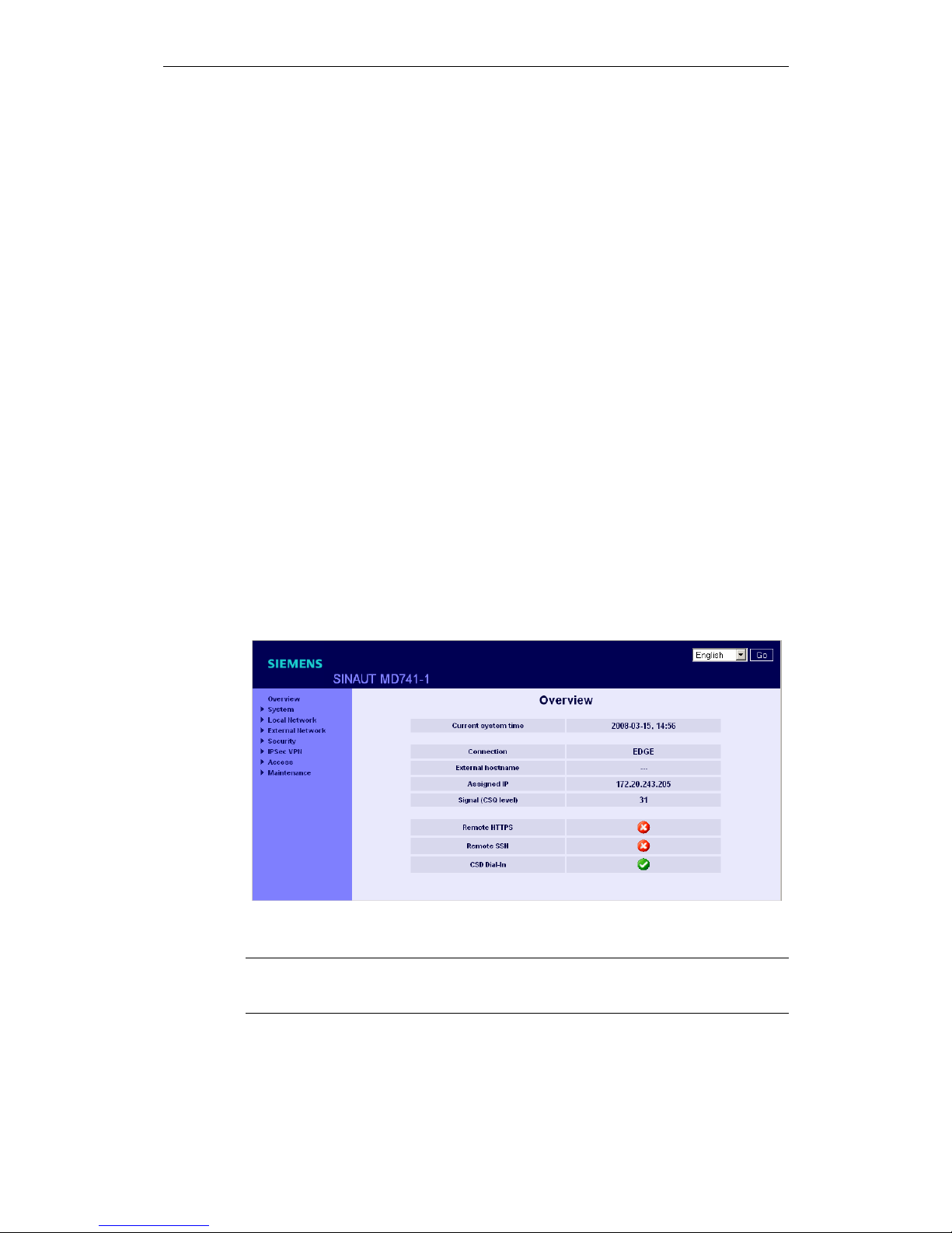
3.3 Start page of the Web user interface
After the Web user interface of the SINAUT MD741-1 is called up and the user
name and password are entered, an overview of the current operating state of the
SINAUT MD741-1 appears.
Figure 3-4 Overview
Note
Use the Refresh function of the Web browser to update the displayed values.

Configuration
SINAUT MD741-1
C79000- G8976-C212
29
Current system time
Shows the current system time of the SINAUT MD741-1 in the format:
Year – Month – Day, Hours – Minutes
Connection
Shows if a wireless connection exists, and which one:
● EDGE connection (IP connection via EGPRS)
● GPRS connection (IP connection via GPRS)
● CSD connection (service connection via CSD)
External hostname
Shows the hostname (e.g. md741.mydns.org) of the SINAUT MD741-1, if a
DynDNS service is being used.
Signal (CSQ level)
Indicates the strength of the GSM signal as a CSQ value.
● CSQ < 6: Poor signal strength
● CSQ= 6..10: Medium signal strength
● CSQ=11-18: Good field strength
● CSQ > 18: Very good field strength
● CSQ = 99: No connection to the GSM network
Assigned IP address
Shoes the IP address at which the SINAUT MD741-1 can be reached in EGPRS or
GPRS. This IP address is assigned to the SINAUT MD741-1 by EGPRS or GPRS.
Note
It may occur that an EDGE (EGPRS) or GPRS connection and an assigned IP
address are both shown, but the connection quality is still not good enough to
transmit data. For this reason we recommend using the active connection
monitoring (see Chapter 5.2).

Configuration
SINAUT MD741-1
30 C79000- G8976-C212
Remote HTTPS
Shows whether remote access to the Web user interface of the SINAUT MD741-1
via EGPRS, GPRS or CSD is permitted (see Chapter 8.1).
● White check mark at green dot: Access is allowed.
● White cross at red dot: Access is not allowed.
Remote SSH
Shows whether remote access to the SSH console of the SINAUT MD741-1 via
EGPRS, GPRS or CSD is permitted (see Chapter 8.2).
● White check mark at green dot: Access is allowed.
● White cross at red dot: Access is not allowed.
CSD Dial-In
Shows whether remote CSD service calls are allowed (see Chapter 8.3).
● White check mark at green dot: Access is allowed.
● White cross at red dot: Access is not allowed.
 Loading...