

Siemens SINAUT MD720-3 System Manual

SIMATIC NET
GPRS/GSM-Modem
SINAUT MD720-3
System manual
Preface, Contents
Introduction
1
Inserting the SIM card
2
Connecting the device and
switching on the device
3
SINAUT MD720-3 in Terminal
Mode
4
SINAUT MD720-3 in OPC Mode
5
Service function
6
Technical Data
7
Glossary
C79000-G8976-C211
Release 06/2006
2
Safety Guidelines
This manual contains notices you have to observe in order to ensure your personal safety, as well as to prevent
damage to property. The notices referring to your personal safety are highlighted in the manual by a safety alert
symbol, notices referring only to property damage have no safety alert symbol. These notices shown below are
graded according to the degree of danger.
!
Danger
indicates that death or severe personal injury will result if proper precautions are not taken.
!
Warning
indicates that death or severe personal injury may result if proper precautions are not taken.
!
Caution
with a safety alert symbol, indicates that minor personal injury can result if proper precautions are not taken.
Caution
without a safety alert symbol, indicates that property damage can result if proper precautions are not taken.
Notice
indicates that an unintended result or situation can occur if the corresponding information is not taken into
account.
If more than one degree of danger is present, the warning notice representing the highest degree of danger will
be used. A notice warning of injury to persons with a safety alert symbol may also include a warning relating to
property damage.
Qualified Personnel
The device/system may only be set up and used in conjunction with this documentation. Commissioning and
operation of a device/system may only be performed by qualified personnel. Within the context of the safety notes
in this documentation qualified persons are defined as persons who are authorized to commission, ground and
label devices, systems and circuits in accordance with established safety practices and standards.
Prescribed Usage
Note the following:
!
Warning
This device may only be used for the applications described in the catalog or the technical description and only in
connection with devices or components from other manufacturers which have been approved or recommended
by Siemens. Correct, reliable operation of the product requires proper transport, storage, positioning and
assembly as well as careful operation and maintenance.
Trademarks
All names identified by ® are registered trademarks of the Siemens AG. The remaining trademarks in this
publication may be trademarks whose use by third parties for their own purposes could violate the rights of the
owner.
Disclaimer of Liability
We have reviewed the contents of this publication to ensure consistency with the hardware and software
described. Since variance cannot be precluded entirely, we cannot guarantee full consistency. However, the
information in this publication is reviewed regularly and any necessary corrections are included in subsequent
editions.
Siemens AG
Automation and Drives
Postfach 48 48
90437 NÜRNBERG
DEUTSCHLAND
Order No.: C79000-G8976-C211-02
Release 06/2006
Copyright © Siemens AG 2006
Technical data subject to change

SINAUT MD720-3
C79000-G8976-C211
3
General
The product SINAUT MD720-3 complies with European standard EN60950, 05.2003,
Safety of Information Technology Equipment.
Read the installation instructions carefully before using the device.
Keep the device away from children, especially small children.
The device must not be installed or operated outdoors or at damp locations.
Do not operate the device if the connecting leads or the device itself are damaged.
External power supply
Use only an external power supply which also complies with EN60950. The output
voltage of the external power supply must not exceed 30VDC. The output of the
external power supply must be short-circuit proof.
!
Warning
The SINAUT MD720-3 may be powered only by power supply units according to
IEC/EN60950 section 2.5 "Limited power sources".
The power supply unit to supply the SINAUT MD720-3 must comply with NEC Class 2
circuits as outlined in the National Electrical Code (ANSI/NFPA 70) only.
When connecting to a battery or accumulator, make sure that an all-pole circuitbreaker (main battery switch) with sufficient selectivity and a fuse with sufficient
selectivity (e.g. Pudenz FKS Fuse 32V, 3A, Order-No. 162.6185.430) are provided
between the device and the battery or accumulator.
Please pay regard to section 7 Technical Data of the system manual, as well as the
installation and utilization regulations of the respective manufacturers of the power
supply, the battery or the accumulator.
SIM card
To install the SIM card the device must be opened. Before opening the device,
disconnect it from the supply voltage. Static charges can damage the device when it is
open. Discharge the electric static of your body before opening the device. To do so,
touch an earthed surface, e.g. the metal casing of the switch cabinet. Please pay
regard to section 2 Inserting the SIM card of this system manual.

SINAUT MD720-3
4 C79000-G8976-C211
Handling cables
Never pull a cable connector out of a socket by its cable, but pull on the connector
itself. Cable connectors with screw fasteners (D-Sub) must always be screwed on
tightly. Do not lay the cable over sharp corners and edges without edge protection. If
necessary, provide sufficient strain relief for the cables.
For safety reasons, make sure that the bending radius of the cables is observed.
Failure to observe the bending radius of the antenna cable results in the deterioration
of the system's transmission and reception properties. The minimum bending radius
static must not fall below 5 times the cable diameter and dynamic below 15 times the
cable diameter.
Radio device
!
Warning
Never use the device in places where the operation of radio devices is prohibited. The
device contains a radio transmitter which could in certain circumstances impair the
functionality of electronic medical devices such as hearing aids or pacemakers. You
can obtain advice from your physician or the manufacturer of such devices. To
prevent data carriers from being demagnetized, do not keep disks, credit cards or
other magnetic data carriers near the device.
Installing antennas
!
Warning
The emission limits as recommended by the Commission on Radiological Protection
(13/14 September 2001) must be observed.
Installing an external antenna
Caution
When installing an antenna outdoors it is essential that the antenna is fitted correctly
by a qualified person. Lightning Protection Standard VDE V 0185 Sections 1 to 4, in
its current version, and further standards must be observed.

SINAUT MD720-3
C79000-G8976-C211
5
Lightning protection category for buildings
Caution
For outdoor installation, the antenna may be fitted only within the lightning protection
zones O/E or 1. These lightning protection zones are prescribed by the lightning
protection spherical radius.
The EMV lightning protection zone concept
Caution
The EMV lightning protection zone concept is to be observed. To avoid large induction
loops a lightning protection equipotential bonding is to be used. If the antenna or
antenna cable is installed near to the lightning protection system, the minimum
distances to the lightning protection system must be observed. If this is not possible,
insulated installation as described in VDE V 0185 Sections 1 to 4, in its current
version, is essential.
FCC Part 15
This equipment has been tested and found to comply with the limits for a Class A
digital device, pursuant to Part 15 of the FCC Rules. These limits are designed to
provide reasonable protection against harmful interference in a residential installation.
This equipment generates, uses and can radiate radio frequency energy and, if not
installed and used in accordance with the instructions, may cause harmful interference
to radio communications. However, there is no guarantee that interference will not
occur in a particular installation. If this equipment does cause harmful interference to
radio or television reception, which can be determined by turning the equipment off
and on, the user is encouraged to try to correct the interference by one or more of the
following measures:
• Reorient or relocate the receiving antenna.
• Increase the separation between the equipment and receiver.
• Connect the equipment into an outlet on a circuit different from that to which
the receiver is connected.
• Consult the dealer / installer or an experienced radio/TV technician for help.

SINAUT MD720-3
6 C79000-G8976-C211
FCC Part 15.19
This device complies with Part 15 of the FCC Rules. Operation is subject to the
following two conditions:
1. this device may not cause harmful interference, and
2. this device must accept any interference received, including interference that
may cause undesired operation.
FCC Part 15.21
Modifications not expressly approved by this company could void the user's authority
to operate the equipment.
Installation by qualified personnel only
You may only use the SINAUT MD720-3 with an antenna of the SINAUT MD720-3
accessory program.
The installation of the SINAUT MD720-3 and the antenna as well as servicing is to be
performed by qualified technical personnel only. When servicing the antenna, or
working at distances closer than those listed below, ensure the transmitter has been
disabled.
RF Exposure mobile
Caution
Typically, the antenna connected to the transmitter is an omni-directional antenna with
0dB gain. Using this antenna the total composite power in PCS mode is smaller than 1
watt ERP.
The internal / external antennas used for this mobile transmitter must provide a
separation distance of at least 20 cm from all persons and must not be co-located
or operating in conjunction with any other antenna or transmitter."
Caution
This is a class A equipment. This equipment can disturb other electric equipment in
living areas; in this case the operator can be demanded to carry out appropriate
measures.
Caution
Please note that data packets exchanged for setting up connections, reconnecting,
connect attempts (e.g. Server switched off, wrong destination address, etc.) as well as
keeping the connection alive are also subject to charge.

SINAUT MD720-3
C79000-G8976-C211
7
Preface
Purpose of this documentation
This documentation will support you on your way to successful application of
SINAUT MD720-3. It will introduce you to the topic in clear and
straightforward steps and provide you with an overview of the hardware of
the SINAUT MD720-3 GSM/GPRS modem. This documentation will help you
during installation and commissioning of SINAUT GSM/GPRS modem and
explains the diagnostics and service options available.
Validity of the documentation
This manual relates to the following product versions
• GPRS/GSM modem MD720-3 hardware release 3.x
SIMATIC Technical Support
You can contact Technical Support for all A&D products
• Phone: +49 (0) 180 5050 222
• Fax: +49 (0) 180 5050 223
You will find further information on our Technical Support on the Web at
http://www.siemens.com/automation/service
Service & Support on the Internet
In addition to our documentation services, you can also make use of all our
knowledge on the Internet:
http://www.siemens.com/automation/service&support
Here, you will find:
• Up-to-date product information (Updates), FAQs (Frequently Asked
Questions), Downloads, Tips and Tricks.
• The Newsletter keeps you constantly up to date with the latest
information on the products you use.
• The Knowledge Manager will find the documents you need.
• In the Forum, users and specialists exchange information and
experience.
• You can find your local contact for Automation & Drives in our contacts
database.
• You will find information on local service, repairs, spares and much more
under the rubric "Service".
You will find the latest version of this documentation under the entry ID
22549543.

Preface
SINAUT MD720-3
8 C79000-G8976-C211
Do you still have questions relating to the use of the products described in
the manual? If so, then please talk to your local Siemens contact.
You will find the addresses in the following sources:
• On the Internet at: http://www.siemens.com/automation/partner
• On the Internet at http://www.siemens.com/simatic-net specifically for
SIMATIC NET products
• In the catalog CA 01
• In the catalog IK PI specifically for SIMATIC NET products
SIMATIC training center
To familiarize you with the systems and products, we offer a range of
courses. Please contact your regional training center or the central training
center in
D-90327 Nuernberg.
Phone: +49 (911) 895-3200
http://www.sitrain.com
SIMATIC NET training center
For courses specifically on products from SIMATIC NET, please contact:
SIEMENS AG
Siemens AG, A&D Informations- und Trainings-Center
Dynamostr. 4
D-68165 Mannheim
Phone: +49 (621) 4 56-23 77
Fax: +49 (621) 4 56-32 68

SINAUT MD720-3
C79000-G8976-C211
9
Contents
Preface.......................................................................................................................................... 7
1 Introduction................................................................................................................... 11
2 Inserting the SIM card .................................................................................................. 13
3 Connecting the device and switching on the device................................................ 19
4 SINAUT MD720-3 in Terminal Mode............................................................................ 23
4.1 Terminal mode activation................................................................................... 23
4.2 Operating requirements in Terminal Mode: GPRS subscriber contract ............ 24
4.3 Functions of the LEDs in Terminal Mode .......................................................... 24
4.4 Terminal mode operation................................................................................... 25
4.5 Entering AT commands ..................................................................................... 26
4.6 Use AT commands ............................................................................................ 28
4.7 Supported AT commands in Terminal Mode..................................................... 30
5 SINAUT MD720-3 in OPC Mode................................................................................... 57
5.1 OPC Mode activation......................................................................................... 58
5.2 Operating requirements in OPC Mode: GPRS subscriber contract .................. 58
5.3 Functions of the LEDs in OPC Mode................................................................. 59
5.4 PIN in OPC-Mode .............................................................................................. 60
5.5 Log in to SINAUT MICRO SC............................................................................ 62
6 Service functions.......................................................................................................... 63
6.1 Switching between Terminal mode and OPC Mode.......................................... 63
6.2 Getting the current settings and values ............................................................. 65
6.3 Service mode to download a new firmware....................................................... 66
6.4 Load factory defaults ......................................................................................... 70
7 Technical Data .............................................................................................................. 71
Glossary ..................................................................................................................................... 75

Contents
SINAUT MD720-3
10 C79000-G8976-C211

SINAUT MD720-3
C79000-G8976-C211
11
Introduction
1
The SINAUT MD720-3 has two different operation modes:
Terminal Mode
OPC Mode
The functional range and the functionality of the device are different in both modes.
The change between OPC Mode and Terminal Mode (refer to page 23 or page 58)
forces a restart of the device.
Terminal mode
The SINAUT MD720-3 establishes radio data connections via a GSM network
(Global System for Mobile Communication).
• using modem connections via CSD (Circuit Switched Data),
• by sending SMS (Short Message Service).
Notice
You will find further information about the Terminal Mode and its use in
combination with TIM devices of the SINAUT ST7 system in the system manual of
the SINAUT ST7.

Introduction
SINAUT MD720-3
12 C79000-G8976-C211
OPC-Modus
The SINAUT MD720-3 transmits data over via a GSM radio network (Global
System for Mobile Communication).
using GPRS (General Packet Radio Service) between S7-200 devices and an
OPC server SINAUT MICRO SC,
using SMS from a S7-200-device to any remote station, which can receive
SMS.
Therefore the SINAUT MD720-3 will be configured by program building blocks of
the connected PLC. The SINAUT MD720-3 establishes autonomous the radio data
connection via GPRS between a S7-200 device and the OPC server SINAUT
MICRO SC.
Notice
You will find information about the OPC Mode in the system manual of the SINAUT
MICRO SC.

SINAUT MD720-3
C79000-G8976-C211
13
Inserting the SIM card
2
Notice
• The device must be switched off when you insert or change the SIM card.
• A plug-in SIM card (3 V) is used.
Changing the SIM card
If you change the SIM card, please do not forget to update also the PIN number in
your application.
If you use a lot of SIM cards it can be helpful to set all PINs to the same PIN
number. You can do this i.e. by using a mobile phone. Please observe the security
requirements of your organization.
To insert the SIM card proceed as follows:
1. Make sure that the device is disconnected from the supply voltage.
2. The SINAUT MD720-3 must be opened to insert the SIM card.
The housing is fastened by two clamps, one on top of the housing and one on the
bottom side (see figure 2-1).
figure 2-1
1 - Clamp
2 - Clamp
Inserting the SIM card
SINAUT MD720-3
14 C79000-G8976-C211
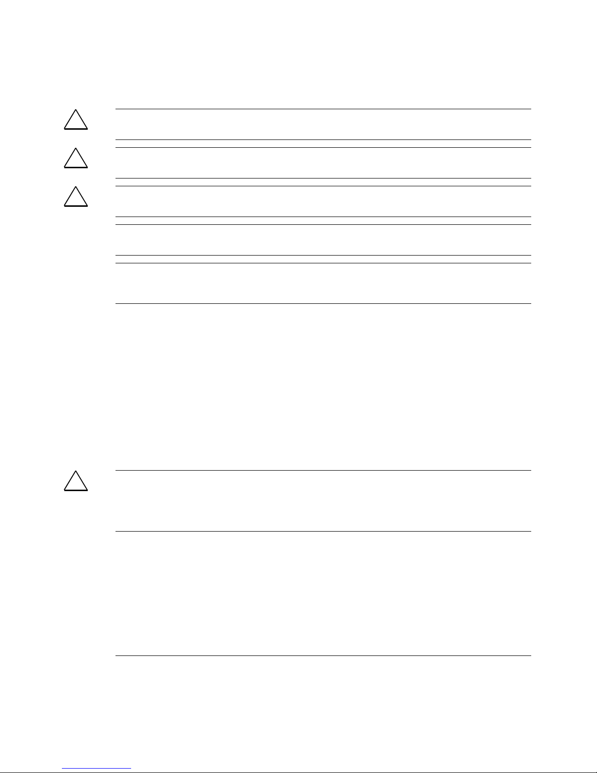
3. With a suitable object press one of the clamps cautiously (see figure 2-2) so
that the catch opens.
figure 2-2
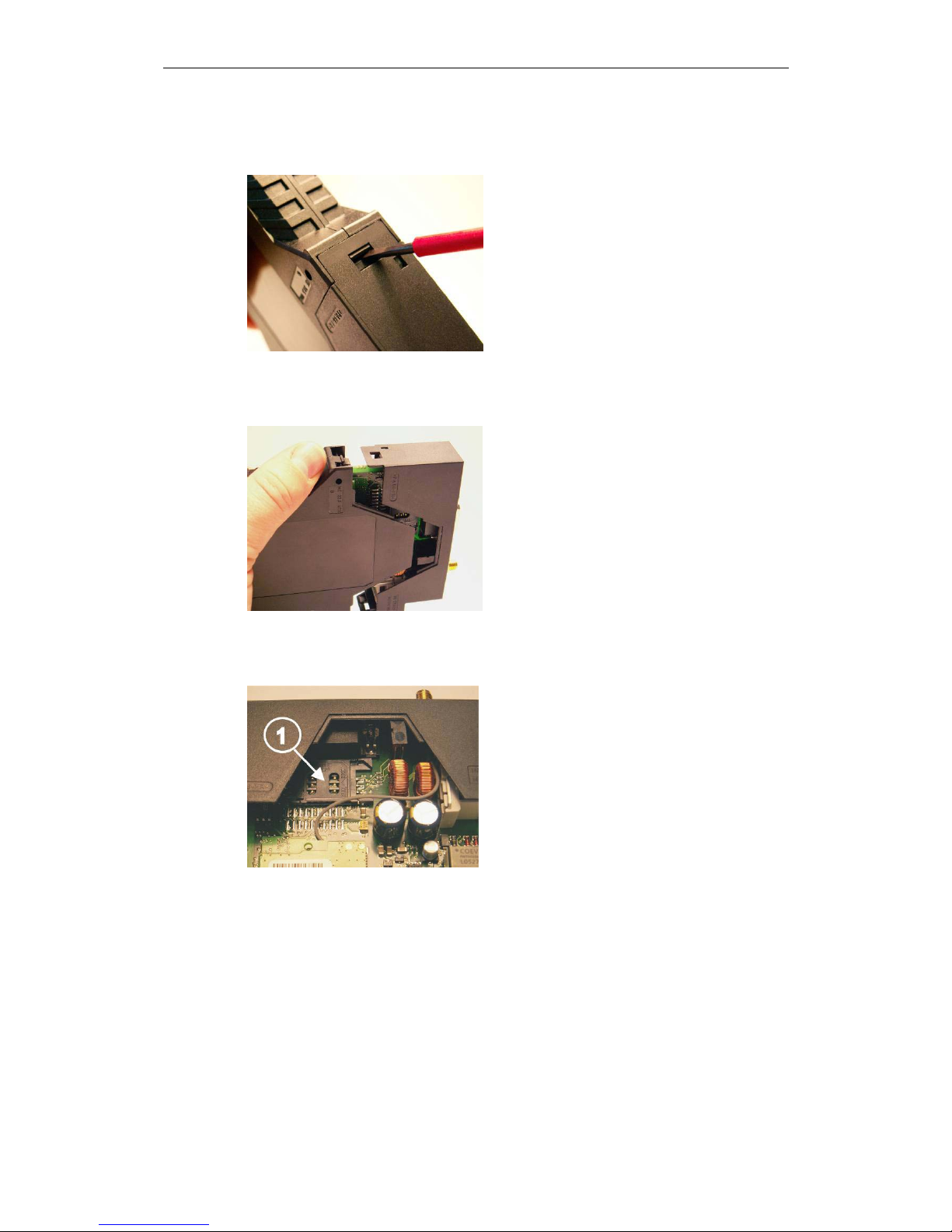
4. Remove the rear section of the housing (see figure 2-3).
figure 2-3
5. The SIM card holder is visible on the motherboard. (see figure 2-4).
figure 2-4
1 - SIM card holder
Inserting the SIM card
SINAUT MD720-3
C79000-G8976-C211
15
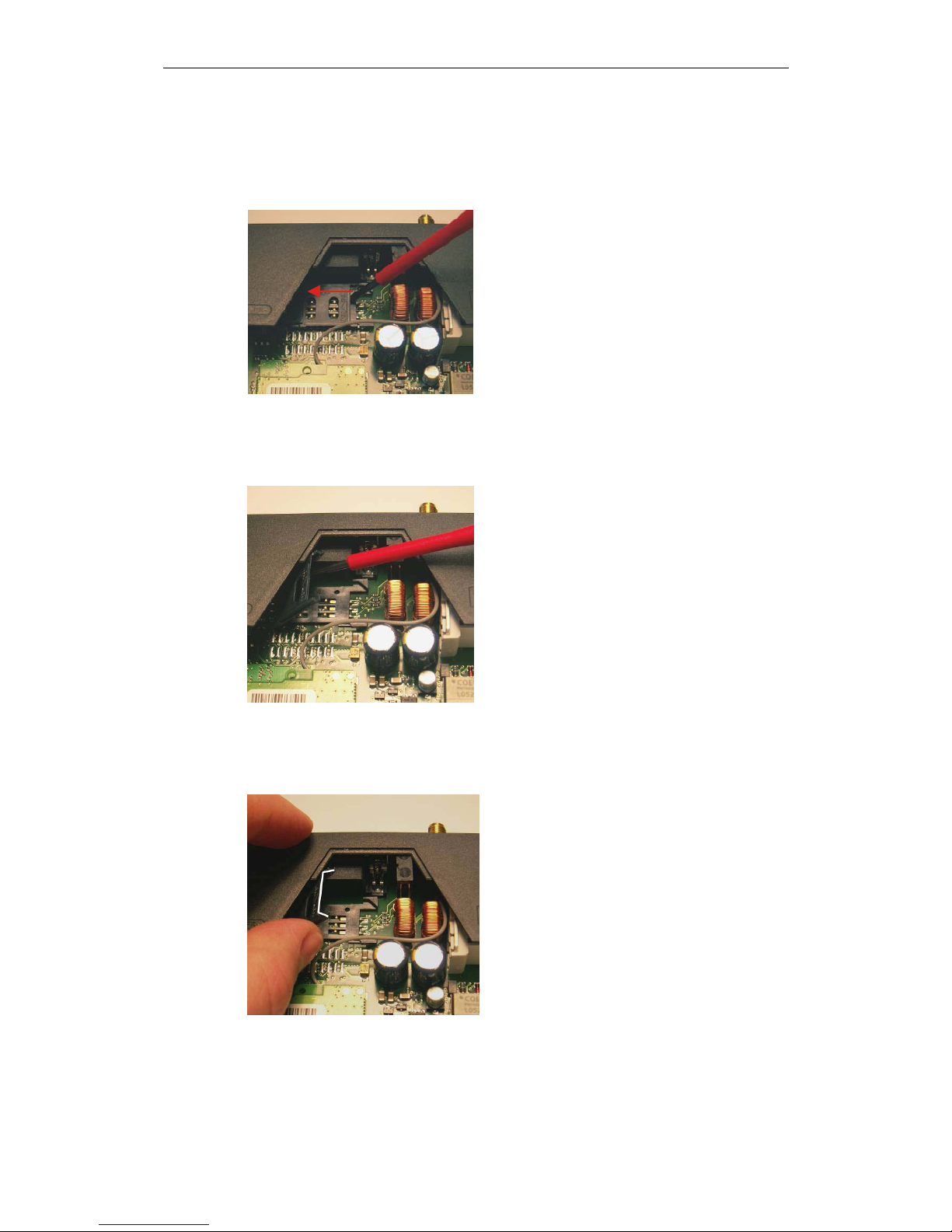
6. With a suitable object open the flap of the SIM card holder by moving it
cautiously about 2 mm to the left - in the direction of the arrow (see red arrow in
figure 2-5) so that it can be raised.
figure 2-5
7. Raise the flap of the SIM card holder so that you can insert the SIM card. (see
figure 2-6).
figure 2-6
8. In figure 2-7, the compartment into which you can insert the SIM card is
emphasized in white.
figure 2-7
Inserting the SIM card
SINAUT MD720-3
16 C79000-G8976-C211
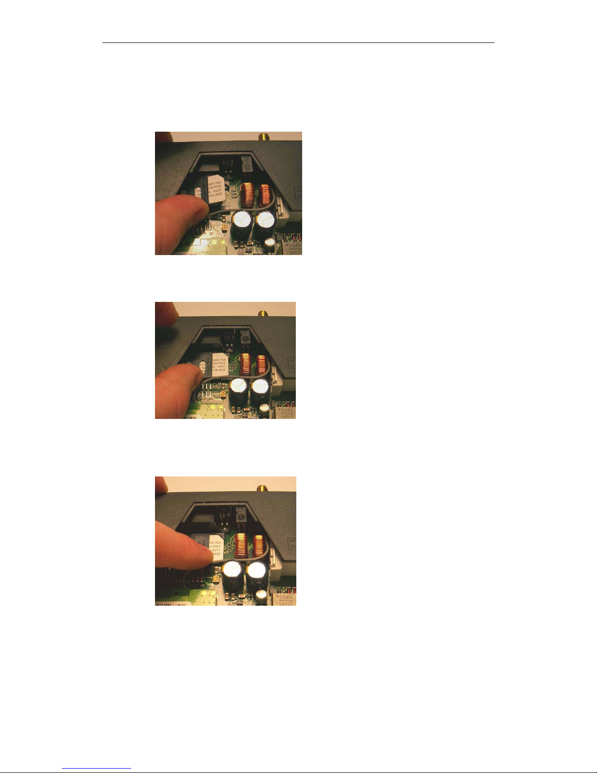
9. Slide the SIM card into the flap of the SIM card holder, with the gold-coloured
microchip pointing down. The flap has a groove for this purpose. The notched
corner of the SIM card has to point towards the front of the device (see figure 2-
8).
figure 2-8
10. Slide the SIM card down into the flap as far as possible (see figure 2-9).
figure 2-9
11. Lower the flap paying attention to the notched corner of the SIM card (see figure
2-10).
figure 2-10

Inserting the SIM card
SINAUT MD720-3
C79000-G8976-C211
17
12. With your fingernail or a suitable object move the flap about 2 mm to the right
(in the direction of the arrow, see figure 2-11) until you can feel it click into
place.
figure 2-11
13. Now the SIM card holder is locked into position (see figure 2-12).
figure 2-12
14. Finally re-attach both housing parts:
Slide the motherboard into the rails on top and bottom inside the rear section of
the housing. Close the housing by slightly pressing both housing parts together
so that the clamps on the upper and lower part of the housing engage (see
figure 2-13).
figure 2-13
1 - SIM card holder

Inserting the SIM card
SINAUT MD720-3
18 C79000-G8976-C211
15. The housing is locked when both clamps have clicked shut (see figure 2-14).
figure 2-14
SINAUT MD720-3
C79000-G8976-C211
19
Connecting the device and switching on
the device
3
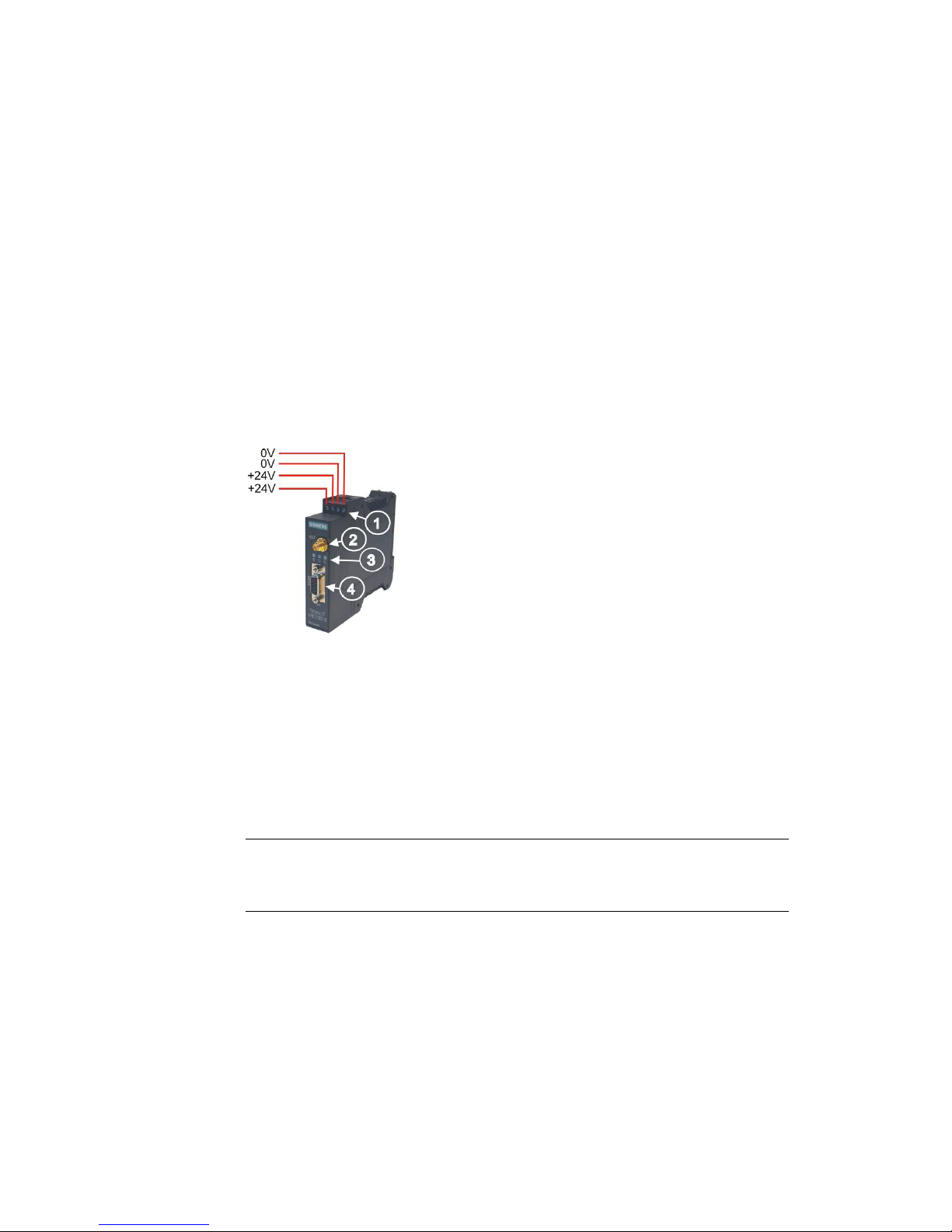
Connectors and LEDs
figure 3-1
Antenna
The antenna connector – SMA socket - is situated on the upper part of the front.
Impedance: approx. 50 Ohm
Caution
Please use only antennas of the SINAUT MD720-3 accessory program. Other
antennas may disturb the product characteristics and may even cause defects.
1 - Connectors for supply voltage
24 V DC voltage (nominal)
2 - Antenna
3 - LEDs: S (Status)
Q (Quality)
C (Connect)
4 - X1 (RS232)
For connection of the application
OR
or the service PC

Connecting the device and switching on the device
SINAUT MD720-3
20 C79000-G8976-C211
Connectors for current supply
The screw terminals on the top of the device are for connecting the current supply:
24 V DC voltage (nominal), I
typ. 165mA at 24V. (Please also refer to chapter 7
Technical Data.)
Both screw terminals on the left (24V) are internally connected, see figure 3-1.
Both screw terminals on the right (0V) are internally connected.
Switching on
The devices switch on as soon as the operating voltage is supplied.
Functions of the LEDs
The SINAUT MD720-3 has three LEDs, which are used to indicate the device
status. The function of the LEDs is different in terminal and OPC Mode. You will
find the explanation of the function
● in Terminal Mode in chapter 4.3 Functions of the LEDs in Terminal Mode and
● in OPC Mode in chapter 5.3 Functions of the LEDs in OPC Mode.
Serial interface X1
For data transmission:
Connect the application (e.g. machine, vending machine, sensor, computer) with
the interface X1 of the SINAUT MD720-3. To connect, use a RS-232 cable.
If the application has a different interface, e.g. CAN, PPI cable or a different
industry bus, a commercially available interface converter can be connected
between it and the SINAUT MD720-3.
OR
For configuration and service:
Connect the service PC via its serial interface (COM port). To connect, use a RS232 cable.

Connecting the device and switching on the device
SINAUT MD720-3
C79000-G8976-C211
21
The SET button
By pushing the SET button for a certain period of time, you can configure the
device or activate different service modes.
Pushing the SET button LED Status Function
while connecting the supply
voltage
The LEDs start to light
up in sequence
signalling the boot
sequence
Switch between the
operating modes
Terminal Mode OPC
Mode
during operation for less
than 2 seconds
The LED „S“ (Status)
begins to light
Dump of current
settings and values
issued via the RS232
interface
during operation for 2-4
seconds
The LED „Q“ (Quality)
begins to light
Service mode to
download a new
firmware
during operation for more
than 4 seconds
Die LED „C“
(Connect) begins to
light
Load factory settings
Top-hat rail mounting
The SINAUT MD720-3 is suitable for top-hat rail mounting on DIN EN 50022 rails.
A corresponding bracket can be found at the rear of the device.

Connecting the device and switching on the device
SINAUT MD720-3
22 C79000-G8976-C211

SINAUT MD720-3
C79000-G8976-C211
23
SINAUT MD720-3 in Terminal Mode
4
In the Terminal Mode the SINAUT MD720-3 operates like a GSM modem, which is
controlled by AT commands.
Supported are
• incoming and outgoing GSM data connections with 9600 bps with modems
being connected to the GSM network, the ISDN or the analogue telephone
network,
• sending of SMS (Short Message Service).
4.1 Terminal mode activation
Terminal mode is the factory default setting
The SINAUT MD720-3 supports two fundamental operation modes:
• Terminal Mode,
• OPC Mode.
The SINAUT MD720-3 is delivered by the factory with activated Terminal Mode.
Switching from OPC Mode into the Terminal Mode
If it is necessary to switch a manually the SINAUT MD720-3 from OPC Mode into
the Terminal Mode, you will find the instructions for this in the chapter Switching
between Terminal mode and OPC Mode.
 Loading...