

Siemens SINAMICS V90, SIMOTICS S-1FL6 Operating Instructions Manual

SINAMICS V90, SIMOTICS S-1FL6
___________________
___________________
___________________
___________________
___________________
___________________
___________________
___________________
___________________
___________________
___________________
___________________
___________________
SINAMICS/SIMOTICS
SINAMICS V90, SIMOTICS S-1FL6
Operating Instructions
07/2015
6SL3298
Preface
Safety instructions
1
General information
2
Mounting
3
Connecting
4
Commissioning
5
Basic operator panel (BOP)
6
Control functions
7
Safety Integrated function
8
Tuning
9
Parameters
10
Diagnostics
11
Appendix
A
-0AV60-0BP0

Siemens AG
Division Digital Factory
Postfach 48 48
90026 NÜRNBERG
GERMANY
Order number: 6SL3298-0AV60-0BP0
Ⓟ
Copyright © Siemens AG 2013 - 2015.
All rights reserved
Legal information
Warning notice system
DANGER
indicates that death or severe personal injury will result if proper precautions are not taken.
WARNING
indicates that death or severe personal injury may result if proper precautions are not taken.
CAUTION
indicates that minor personal injury can result if proper precautions are not taken.
NOTICE
indicates that property damage can result if proper precautions are not taken.
Qualified Personnel
personnel qualified
Proper use of Siemens products
WARNING
Siemens products may only be used for the applications described in the catalog and in the relevant technical
maintenance are required to ensure that the products operate safely and without any problems. The permissible
ambient conditions must be complied with. The information in the relevant documentation must be observed.
Trademarks
Disclaimer of Liability
This manual contains notices you have to observe in order to ensure your personal safety, as well as to prevent
damage to property. The notices referring to your personal safety are highlighted in the manual by a safety alert
symbol, notices referring only to property damage have no safety alert symbol. These notices shown below are
graded according to the degree of danger.
If more than one degree of danger is present, the warning notice representing the highest degree of danger will
be used. A notice warning of injury to persons with a safety alert symbol may also include a warning relating to
property damage.
The product/system described in this documentation may be operated only by
task in accordance with the relevant documentation, in particular its warning notices and safety instructions.
Qualified personnel are those who, based on their training and experience, are capable of identifying risks and
avoiding potential hazards when working with these products/systems.
Note the following:
documentation. If products and components from other manufacturers are used, these must be recommended
or approved by Siemens. Proper transport, storage, installation, assembly, commissioning, operation and
All names identified by ® are registered trademarks of Siemens AG. The remaining trademarks in this publication
may be trademarks whose use by third parties for their own purposes could violate the rights of the owner.
We have reviewed the contents of this publication to ensure consistency with the hardware and software
described. Since variance cannot be precluded entirely, we cannot guarantee full consistency. However, the
information in this publication is reviewed regularly and any necessary corrections are included in subsequent
editions.
for the specific
07/2015 Subject to change

Preface
Documentation components
Document
Content
Operating Instructions
(this manual)
basic commissioning of the SINAMICS V90 servo system.
and relevant safety notices.
Target group
Technical support
Country
Hotline
China
+86 400 810 4288
Germany
+49 911 895 7222
Italy
+39 (02) 24362000
India
+91 22 2760 0150
Turkey
+90 (216) 4440747
Support contacts (http://support.automation.siemens.com/WW/view/en/16604999)
Getting Started Describes how to install, connect, operate, and perform
SIMOTICS S-1FL6 Servo Motors Installation Guide Describes how to install the SMOTICS S-1FL6 servo motor
This manual provides information about the SINAMICS V90 servo system for planners,
operators, mechanical engineers, electrical engineers, commissioning engineers, and
service engineers.
Further service contact information:
SINAMICS V90, SIMOTICS S-1FL6
Operating Instructions, 07/2015, 6SL3298-0AV60-0BP0
3

Preface
SINAMICS V90, SIMOTICS S-1FL6
4 Operating Instructions, 07/2015, 6SL3298-0AV60-0BP0

Table of contents
Preface ................................................................................................................................................... 3
1 Safety instructions ................................................................................................................................. 11
2 General information .............................................................................................................................. 27
3 Mounting ............................................................................................................................................... 53
4 Connecting ........................................................................................................................................... 63
1.1 Fundamental safety instructions ............................................................................................. 11
1.1.1 General safety instructions ..................................................................................................... 11
1.1.2 Safety instructions for electromagnetic fields (EMF) .............................................................. 15
1.1.3 Handling electrostatic sensitive devices (ESD) ...................................................................... 15
1.1.4 Industrial security .................................................................................................................... 16
1.1.5 Residual risks of power drive systems .................................................................................... 16
1.2 Additional safety instructions .................................................................................................. 18
1.2.1 Residual risks during the operation of electric motors ............................................................ 25
2.1 Deliverables ............................................................................................................................ 27
2.1.1 Drive components ................................................................................................................... 27
2.1.2 Motor components .................................................................................................................. 29
2.2 Device combination ................................................................................................................. 31
2.3 Product overview .................................................................................................................... 32
2.4 System configuration .............................................................................................................. 34
2.5 Accessories ............................................................................................................................. 35
2.6 Function list ............................................................................................................................. 41
2.7 Technical data ......................................................................................................................... 43
2.7.1 Technical data - servo drives .................................................................................................. 43
2.7.2 Technical data - servo motors ................................................................................................ 46
2.7.3 Technical data - cables ........................................................................................................... 51
3.1 Mounting the drive .................................................................................................................. 53
3.1.1 Mounting orientation and clearance ........................................................................................ 53
3.1.2 Drill patterns and outline dimensions ...................................................................................... 54
3.1.3 Mounting the drive .................................................................................................................. 56
3.2 Mounting the motor ................................................................................................................. 57
3.2.1 Mounting orientation and dimensions ..................................................................................... 57
3.2.2 Mounting the motor ................................................................................................................. 60
4.1 System connection .................................................................................................................. 63
4.2 Main circuit wirings .................................................................................................................. 65
4.2.1 Line supply - L1, L2, L3........................................................................................................... 65
4.2.2 Motor power - U, V, W ............................................................................................................ 66
4.3 Control/Status interface - X8 ................................................................................................... 67
SINAMICS V90, SIMOTICS S-1FL6
Operating Instructions, 07/2015, 6SL3298-0AV60-0BP0
5

Table of contents
5 Commissioning .................................................................................................................................... 107
6 Basic operator panel (BOP) ................................................................................................................. 117
4.3.1 Digital inputs/outputs (DIs/DOs) ............................................................................................. 69
4.3.1.1 DIs .......................................................................................................................................... 70
4.3.1.2 DOs ........................................................................................................................................ 74
4.3.2 Pulse train inputs/encoder outputs (PTIs/PTOs) ................................................................... 77
4.3.2.1 PTIs ........................................................................................................................................ 77
4.3.2.2 PTOs ...................................................................................................................................... 78
4.3.3 Analog inputs/outputs (AIs/AOs) ............................................................................................ 78
4.3.3.1 AIs .......................................................................................................................................... 78
4.3.3.2 AOs ........................................................................................................................................ 79
4.3.4 Standard application wirings (factory setting) ........................................................................ 81
4.3.4.1 Pulse train input position control (PTI) ................................................................................... 81
4.3.4.2 Internal position control (IPos) ............................................................................................... 83
4.3.4.3 Speed control (S) ................................................................................................................... 85
4.3.4.4 Torque control (T) .................................................................................................................. 87
4.3.5 Connection examples with PLCs ........................................................................................... 89
4.3.5.1 SIMATIC S7-200 SMART ...................................................................................................... 89
4.3.5.2 SIMATIC S7-200 .................................................................................................................... 93
4.3.5.3 SIMATIC S7-1200 .................................................................................................................. 97
4.4 24V power supply/STO - X6 ................................................................................................ 101
4.5 Encoder interface - X9 ......................................................................................................... 102
4.6 External braking resistor - DCP, R1 ..................................................................................... 105
4.7 Motor holding brake - X7 ...................................................................................................... 105
4.8 RS485 interface - X12 .......................................................................................................... 106
5.1 Initial commissioning in JOG mode...................................................................................... 108
5.2 Commissioning in pulse train position control mode (PTI) .................................................. 110
5.3 Commissioning in internal position control mode (IPos) ...................................................... 112
5.4 Commissioning in speed control mode (S) .......................................................................... 114
5.5 Commissioning in torque control mode (T) .......................................................................... 115
6.1 BOP overview ...................................................................................................................... 117
6.1.1 BOP display ......................................................................................................................... 118
6.1.2 Control buttons ..................................................................................................................... 120
6.2 Parameter structure ............................................................................................................. 121
6.3 Actual status display ............................................................................................................ 122
6.4 Basic operations................................................................................................................... 123
6.4.1 Editing parameters ............................................................................................................... 124
6.4.2 Viewing parameters ............................................................................................................. 126
6.4.3 Searching parameters in "P ALL" menu .............................................................................. 126
6.5 Auxiliary functions ................................................................................................................ 127
6.5.1 Jog ....................................................................................................................................... 128
6.5.2 Saving parameters (RAM to ROM) ...................................................................................... 129
6.5.3 Setting parameters to default ............................................................................................... 129
6.5.4 Transferring data (drive to SD) ............................................................................................ 130
SINAMICS V90, SIMOTICS S-1FL6
6 Operating Instructions, 07/2015, 6SL3298-0AV60-0BP0

Table of contents
7 Control functions ................................................................................................................................. 135
6.5.5 Transferring data (SD to drive) ............................................................................................. 131
6.5.6 Updating firmware ................................................................................................................. 131
6.5.7 Adjusting AI offsets ............................................................................................................... 132
6.5.8 Adjusting an absolute encoder ............................................................................................. 134
7.1 Compound controls ............................................................................................................... 135
7.2 General functions .................................................................................................................. 136
7.2.1 Servo ON .............................................................................................................................. 136
7.2.2 Direction of motor rotation .................................................................................................... 137
7.2.3 Over-travel ............................................................................................................................ 138
7.2.4 Motor holding brake .............................................................................................................. 140
7.2.5 Stopping method at servo OFF ............................................................................................. 142
7.3 Pulse train input position control (PTI) .................................................................................. 143
7.3.1 Sequence of SON ................................................................................................................. 143
7.3.2 Selecting a setpoint pulse train input channel ...................................................................... 143
7.3.3 Selecting a setpoint pulse train input form ............................................................................ 144
7.3.4 In position (INP) .................................................................................................................... 144
7.3.5 Smoothing function ............................................................................................................... 145
7.3.6 Electronic gear ratio .............................................................................................................. 145
7.3.7 Inhibiting pulse train input setpoint (P-TRG) ......................................................................... 149
7.3.8 Speed limit ............................................................................................................................ 150
7.3.9 Torque limit ........................................................................................................................... 151
7.3.10 Clearing droop pulses (CLR) ................................................................................................ 154
7.3.11 Referencing (only for absolute encoder)............................................................................... 155
7.3.12 PTO function ......................................................................................................................... 155
7.4 Internal position control (IPos) .............................................................................................. 157
7.4.1 Setting mechanical system ................................................................................................... 157
7.4.2 Setting fixed position setpoint ............................................................................................... 158
7.4.3 Selecting a positioning mode - absolute/incremental ........................................................... 160
7.4.4 Configuring linear/modular axis ............................................................................................ 161
7.4.5 Backlash compensation ........................................................................................................ 161
7.4.6 Referencing ........................................................................................................................... 162
7.4.7 Software position limit ........................................................................................................... 171
7.4.8 Speed limit ............................................................................................................................ 171
7.4.9 Torque limit ........................................................................................................................... 171
7.4.10 Selecting a fixed position setpoint and starting positioning .................................................. 171
7.5 Speed control (S) .................................................................................................................. 174
7.5.1 Configuring speed setpoint ................................................................................................... 174
7.5.1.1 Speed control with external analog speed setpoint .............................................................. 174
7.5.1.2 Speed control with fixed speed setpoint ............................................................................... 175
7.5.2 Direction and stop ................................................................................................................. 176
7.5.3 Speed limit ............................................................................................................................ 176
Torque limit ........................................................................................................................... 176
7.5.4
5.5 Zero speed clamp ................................................................................................................. 177
7.
7.5.6 Ramp-function generator ...................................................................................................... 178
7.6 Torque control (T) ................................................................................................................. 179
7.6.1 300% overload capacity ........................................................................................................ 179
7.6.2 Torque setpoint ..................................................................................................................... 180
7.6.2.1 Torque control with external analog torque setpoint ............................................................. 180
SINAMICS V90, SIMOTICS S-1FL6
Operating Instructions, 07/2015, 6SL3298-0AV60-0BP0
7

Table of contents
8 Safety Integrated function .................................................................................................................... 201
9 Tuning ................................................................................................................................................. 223
7.6.2.2 Torque control with fixed torque setpoint ............................................................................. 181
7.6.3 Direction and stop ................................................................................................................ 182
7.6.4 Speed limit ........................................................................................................................... 182
7.7 Communicating with the PLC ............................................................................................... 182
7.7.1 USS communication ............................................................................................................ 182
7.7.2 Modbus communication ....................................................................................................... 185
7.8 Absolute position system ..................................................................................................... 197
7.8.1 Transmitting sequence for the absolute position data ......................................................... 198
8.1 Standards and regulations ................................................................................................... 201
8.1.1 General information ............................................................................................................. 201
8.1.1.1 Aims ..................................................................................................................................... 201
8.1.1.2 Functional safety .................................................................................................................. 202
8.1.2 Safety of machinery in Europe ............................................................................................. 202
8.1.2.1 Machinery Directive ............................................................................................................. 203
8.1.2.2 Harmonized European Standards........................................................................................ 203
8.1.2.3 Standards for implementing safety-related controllers ........................................................ 205
8.1.2.4 DIN EN ISO 13849-1 (replaces EN 954-1) .......................................................................... 206
8.1.2.5 EN 62061 ............................................................................................................................. 207
8.1.2.6 Series of standards EN 61508 (VDE 0803) ......................................................................... 208
8.1.2.7 Risk analysis/assessment .................................................................................................... 209
8.1.2.8 Risk reduction ...................................................................................................................... 210
8.1.2.9 Residual risk ......................................................................................................................... 211
8.1.3 Machine safety in the USA ................................................................................................... 211
8.1.3.1 Minimum requirements of the OSHA ................................................................................... 211
8.1.3.2 NRTL listing .......................................................................................................................... 212
8.1.3.3 NFPA 79 ............................................................................................................................... 212
8.1.3.4 ANSI B11 ............................................................................................................................. 213
8.1.4 Machine safety in Japan ...................................................................................................... 214
8.1.5 Equipment regulations ......................................................................................................... 214
8.2 General information about SINAMICS Safety Integrated .................................................... 214
8.3 System features ................................................................................................................... 215
8.3.1 STO functional safety data ................................................................................................... 215
8.3.2 Certification .......................................................................................................................... 215
8.3.3 Safety instructions ................................................................................................................ 215
8.3.4 Probability of failure of the safety function ........................................................................... 217
8.3.5 Response time ..................................................................................................................... 217
8.3.6 Residual risk ......................................................................................................................... 218
8.4 Safety Integrated basic functions ......................................................................................... 218
8.4.1 Safe Torque Off (STO) ......................................................................................................... 218
8.4.2 Forced dormant error detection ........................................................................................... 221
9.1 Controller overview .............................................................................................................. 223
9.2 Tuning mode ........................................................................................................................ 225
9.3 One-button auto tuning ........................................................................................................ 226
9.4 Real-time auto tuning ........................................................................................................... 232
SINAMICS V90, SIMOTICS S-1FL6
8 Operating Instructions, 07/2015, 6SL3298-0AV60-0BP0

Table of contents
10 Parameters ......................................................................................................................................... 253
11 Diagnostics ......................................................................................................................................... 291
A Appendix............................................................................................................................................. 313
Index................................................................................................................................................... 327
9.5 Manual tuning ....................................................................................................................... 236
9.6 Resonance suppression ....................................................................................................... 238
9.7 Low frequency vibration suppression ................................................................................... 241
9.8 Gain switching ....................................................................................................................... 242
9.8.1 Gain switching using an external digital input signal (G-CHANGE) ..................................... 243
9.8.2 Gain switching using position deviation ................................................................................ 244
9.8.3 Gain switching using position setpoint frequency ................................................................. 244
9.8.4 Gain switching using actual speed ....................................................................................... 245
9.9 PI/P switching ....................................................................................................................... 246
9.9.1 PI/P switching using torque setpoint ..................................................................................... 248
9.9.2 PI/P switching using an external digital input signal (G-CHANGE) ...................................... 248
9.9.3 PI/P switching using speed setpoint ..................................................................................... 249
9.9.4 PI/P switching using acceleration setpoint ........................................................................... 250
9.9.5 PI/P switching using pulse deviation ..................................................................................... 251
10.1 Overview ............................................................................................................................... 253
10.2 Parameter list ........................................................................................................................ 255
11.1 Overview ............................................................................................................................... 291
11.2 List of faults and alarms ........................................................................................................ 296
A.1 Order numbers ...................................................................................................................... 313
A.2 Assembly of cable connectors on the motor side ................................................................. 316
A.3 Assembly of cable terminals on the drive side ..................................................................... 318
A.4 Motor selection ...................................................................................................................... 321
A.4.1 Selection procedure .............................................................................................................. 321
A.4.2 Parameter description ........................................................................................................... 322
A.4.3 Selection examples ............................................................................................................... 324
A.5 Replacing fans ...................................................................................................................... 325
SINAMICS V90, SIMOTICS S-1FL6
Operating Instructions, 07/2015, 6SL3298-0AV60-0BP0
9

Table of contents
SINAMICS V90, SIMOTICS S-1FL6
10 Operating Instructions, 07/2015, 6SL3298-0AV60-0BP0
1
1.1
Fundamental safety instructions
1.1.1
General safety instructions
DANGER
Danger to life due to live parts and other energy sources
WARNING
Danger to life through a hazardous voltage when connecting an unsuitable power supply
Death or serious injury can result when live parts are touched.
• Only work on electrical devices when you are qualified for this job.
• Always observe the country-specific safety rules.
Generally, six steps apply when establishing safety:
1. Prepare for shutdown and notify all those who will be affected by the procedure.
2. Disconnect the machine from the supply.
– Switch off the machine.
– Wait until the discharge time specified on the warning labels has elapsed.
– Check that it really is in a no-voltage condition, from phase conductor to phase
conductor and phase conductor to protective conductor.
– Check whether the existing auxiliary supply circuits are de-energized.
– Ensure that the motors cannot move.
3. Identify all other dangerous energy sources, e.g. compressed air, hydraulic systems, or
water.
4. Isolate or neutralize all hazardous energy sources by closing switches, grounding or
short-circuiting or closing valves, for example.
5. Secure the energy sources against switching on again.
6. Ensure that the correct machine is completely interlocked.
After you have completed the work, restore the operational readiness in the inverse
sequence.
Touching live components can result in death or severe injury.
• Only use power supplies that provide SELV (Safety Extra Low Voltage) or PELV-
(Protective Extra Low Voltage) output voltages for all connections and terminals of the
electronics modules.
SINAMICS V90, SIMOTICS S-1FL6
Operating Instructions, 07/2015, 6SL3298-0AV60-0BP0
11
Safety instructions
WARNING
Danger to life when live parts are touched on damaged devices
WARNING
Danger to life through electric shock due to unconnected cable shields
WARNING
Danger to life due to electric shock when not grounded
WARNING
Danger to life due to electric shock when opening plug connections in operation
WARNING
Danger to life due to fire spreading if housing is inadequate
1.1 Fundamental safety instructions
Improper handling of devices can cause damage.
For damaged devices, hazardous voltages can be present at the enclosure or at exposed
components; if touched, this can result in death or severe injury.
• Ensure compliance with the limit values specified in the technical data during transport,
storage and operation.
• Do not use any damaged devices.
Hazardous touch voltages can occur through capacitive cross-coupling due to unconnected
cable shields.
• As a minimum, connect cable shields and the conductors of power cables that are not
used (e.g. brake cores) at one end at the grounded housing potential.
For missing or incorrectly implemented protective conductor connection for devices with
protection class I, high voltages can be present at open, exposed parts, which when
touched, can result in death or severe injury.
• Ground the device in compliance with the applicable regulations.
When opening plug connections in operation, arcs can result in severe injury or death.
• Only open plug connections when the equipment is in a no-voltage state, unless it has
been explicitly stated that they can be opened in operation.
Fire and smoke development can cause severe personal injury or material damage.
• Install devices without a protective housing in a metal control cabinet (or protect the
device by another equivalent measure) in such a way that contact with fire is prevented.
• Ensure that smoke can only escape via controlled and monitored paths.
SINAMICS V90, SIMOTICS S-1FL6
12 Operating Instructions, 07/2015, 6SL3298-0AV60-0BP0
Safety instructions
WARNING
Danger to life through unexpected movement of machines when using mobile wireless
devices or mobile phones
WARNING
Danger to life due to the motor catching fire in the event of insulation overload
WARNING
Danger to life due to fire if overheating occurs because of insufficient ventilation clearances
WARNING
Danger of an accident occurring due to missing or illegible warning labels
1.1 Fundamental safety instructions
Using mobile wireless devices or mobile phones with a transmit power > 1 W closer than
approx. 2 m to the components may cause the devices to malfunction, influence the
functional safety of machines therefore putting people at risk or causing material damage.
• Switch the wireless devices or mobile phones off in the immediate vicinity of the
components.
There is higher stress on the motor insulation through a ground fault in an IT system. If the
insulation fails, it is possible that death or severe injury can occur as a result of smoke and
fire.
• Use a monitoring device that signals an insulation fault.
• Correct the fault as quickly as possible so the motor insulation is not overloaded.
Inadequate ventilation clearances can cause overheating of components with subsequent
fire and smoke. This can cause severe injury or even death. This can also result in
increased downtime and reduced service lives for devices/systems.
• Ensure compliance with the specified minimum clearance as ventilation clearance for
the respective component.
Missing or illegible warning labels can result in accidents involving death or serious injury.
• Check that the warning labels are complete based on the documentation.
• Attach any missing warning labels to the components, in the national language if
necessary.
• Replace illegible warning labels.
SINAMICS V90, SIMOTICS S-1FL6
Operating Instructions, 07/2015, 6SL3298-0AV60-0BP0
13
Safety instructions
NOTICE
Device damage caused by incorrect voltage/insulation tests
WARNING
Danger to life when safety functions are inactive
Note
Important safety notices for Safety Integrated functions
If you want to use Safety Integrated functions, you must observe the safety notices in the
Safety Integrated manuals.
WARNING
Danger to life or malfunctions of the machine as a result of incorrect or changed
parameterization
1.1 Fundamental safety instructions
Incorrect voltage/insulation tests can damage the device.
• Before carrying out a voltage/insulation check of the system/machine, disconnect the
devices as all converters and motors have been subject to a high voltage test by the
manufacturer, and therefore it is not necessary to perform an additional test within the
system/machine.
Safety functions that are inactive or that have not been adjusted accordingly can cause
operational faults on machines that could lead to serious injury or death.
• Observe the information in the appropriate product documentation before
commissioning.
• Carry out a safety inspection for functions relevant to safety on the entire system,
including all safety-related components.
• Ensure that the safety functions used in your drives and automation tasks are adjusted
and activated through appropriate parameterizing.
• Perform a function test.
• Only put your plant into live operation once you have guaranteed that the functions
relevant to safety are running correctly.
As a result of incorrect or changed parameterization, machines can malfunction, which in
turn can lead to injuries or death.
• Protect the parameterization (parameter assignments) against unauthorized access.
• Respond to possible malfunctions by applying suitable measures (e.g. EMERGENCY
STOP or EMERGENCY OFF).
SINAMICS V90, SIMOTICS S-1FL6
14 Operating Instructions, 07/2015, 6SL3298-0AV60-0BP0
Safety instructions
1.1.2
Safety instructions for electromagnetic fields (EMF)
WARNING
Danger to life from electromagnetic fields
1.1.3
Handling electrostatic sensitive devices (ESD)
NOTICE
Damage through electric fields or electrostatic discharge
1.1 Fundamental safety instructions
Electromagnetic fields (EMF) are generated by the operation of electrical power equipment
such as transformers, converters or motors.
People with pacemakers or implants are at a special risk in the immediate vicinity of these
devices/systems.
• Ensure that the persons involved are the necessary distance away (minimum 2 m).
Electrostatic sensitive devices (ESD) are individual components, integrated circuits, modules
or devices that may be damaged by either electric fields or electrostatic discharge.
Electric fields or electrostatic discharge can cause malfunctions through damaged
individual components, integrated circuits, modules or devices.
• Only pack, store, transport and send electronic components, modules or devices in their
original packaging or in other suitable materials, e.g conductive foam rubber of
aluminum foil.
• Only touch components, modules and devices when you are grounded by one of the
following methods:
– Wearing an ESD wrist strap
– Wearing ESD shoes or ESD grounding straps in ESD areas with conductive flooring
• Only place electronic components, modules or devices on conductive surfaces (table
with ESD surface, conductive ESD foam, ESD packaging, ESD transport container).
SINAMICS V90, SIMOTICS S-1FL6
Operating Instructions, 07/2015, 6SL3298-0AV60-0BP0
15
Safety instructions
1.1.4
Industrial security
Note
Industrial security
Siemens provides products and solutions with industrial security functions that support th
secure operation of plants, solutions, machines, equipment and/or networks. They are
important components in a holistic industrial security concept. With this in mind, Siemens’
products and solutions undergo continuous development. Siemens recommends str
that you regularly check for product updates.
For the secure operation of Siemens products and solutions, it is necessary to take suitable
preventive action (e.g. cell protection concept) and integrate each component into a holistic,
state
also be considered. For more information about industrial security, visit this address
(
To stay informed about product updates as they occur, sign up for a product
newsletter. For more information, visit this address (
).
WARNING
Danger as a result of unsafe operating states resulting from software manipulation
1.1.5
Residual risks of power drive systems
1.1 Fundamental safety instructions
e
ongly
-of-the-art industrial security concept. Third-party products that may be in use should
http://www.siemens.com/industrialsecurity).
-specific
http://support.automation.siemens.com
Software manipulation (e.g. by viruses, Trojan horses, malware, worms) can cause unsafe
operating states to develop in your installation which can result in death, severe injuries
and/or material damage.
• Keep the software up to date.
You will find relevant information and newsletters at this address
(http://support.automation.siemens.com).
• Incorporate the automation and drive components into a holistic, state-of-the-art
industrial security concept for the installation or machine.
You will find further information at this address
(http://www.siemens.com/industrialsecurity).
• Make sure that you include all installed products into the holistic industrial security
concept.
The control and drive components of a drive system are approved for industrial and
commercial use in industrial line supplies. Their use in public line supplies requires a
different configuration and/or additional measures.
These components may only be operated in closed housings or in higher-level control
cabinets with protective covers that are closed, and when all of the protective devices are
used.
SINAMICS V90, SIMOTICS S-1FL6
16 Operating Instructions, 07/2015, 6SL3298-0AV60-0BP0

Safety instructions
1.1 Fundamental safety instructions
These components may only be handled by qualified and trained technical personnel who
are knowledgeable and observe all of the safety instructions on the components and in the
associated technical user documentation.
When assessing the machine's risk in accordance with the respective local regulations (e.g.,
EC Machinery Directive), the machine manufacturer must take into account the following
residual risks emanating from the control and drive components of a drive system:
1. Unintentional movements of driven machine components during commissioning,
operation, maintenance, and repairs caused by, for example,
– Hardware and/or software errors in the sensors, control system, actuators, and cables
and connections
– Response times of the control system and of the drive
– Operation and/or environmental conditions outside the specification
– Condensation/conductive contamination
– Parameterization, programming, cabling, and installation errors
– Use of wireless devices/mobile phones in the immediate vicinity of the control system
– External influences/damage
2. In the event of a fault, exceptionally high temperatures, including an open fire, as well as
emissions of light, noise, particles, gases, etc. can occur inside and outside the inverter,
e.g.:
– Component failure
– Software errors
– Operation and/or environmental conditions outside the specification
– External influences/damage
Inverters of the Open Type/IP20 degree of protection must be installed in a metal control
cabinet (or protected by another equivalent measure) such that contact with fire inside
and outside the inverter is not possible.
3. Hazardous shock voltages caused by, for example,
– Component failure
– Influence during electrostatic charging
– Induction of voltages in moving motors
– Operation and/or environmental conditions outside the specification
– Condensation/conductive contamination
– External influences/damage
4. Electrical, magnetic and electromagnetic fields generated in operation that can pose a
risk to people with a pacemaker, implants or metal replacement joints, etc., if they are too
close
5. Release of environmental pollutants or emissions as a result of improper operation of the
system and/or failure to dispose of components safely and correctly
SINAMICS V90, SIMOTICS S-1FL6
Operating Instructions, 07/2015, 6SL3298-0AV60-0BP0
17
Safety instructions
Note
The components must be protected against conductive contamination (e.g. by installing them
in a control
Assuming that conductive contamination at the installation site can definitely be excluded, a
lower degree of cabinet protection may be permitted.
1.2
Additional safety instructions
WARNING
Danger to life from permanent magnet fields
WARNING
Injury caused by moving parts or those that are flung out
WARNING
Danger to life due to fire if overheating occurs because of insufficient cooling
1.2 Additional safety instructions
cabinet with degree of protection IP54 according to IEC 60529 or NEMA 12).
For more information about residual risks of the components in a drive system, see the
relevant sections in the technical user documentation.
Even when switched off, electric motors with permanent magnets represent a potential risk
for persons with heart pacemakers or implants if they are close to converters/motors.
• If you are such a person (with heart pacemaker or implant) then keep a minimum
distance of 2 m.
• When transporting or storing permanent magnet motors always use the original packing
materials with the warning labels attached.
• Clearly mark the storage locations with the appropriate warning labels.
• IATA regulations must be observed when transported by air.
Touching moving motor parts or drive output elements and loose motor parts that are flung
out (e.g. feather keys) in operation can result in severe injury or death.
• Remove any loose parts or secure them so that they cannot be flung out.
• Do not touch any moving parts.
• Safeguard all moving parts using the appropriate safety guards.
Inadequate cooling can cause overheating resulting in death or severe injury as a result of
smoke and fire. This can also result in increased failures and reduced service lives of
motors.
• Comply with the specified coolant requirements for the motor.
SINAMICS V90, SIMOTICS S-1FL6
18 Operating Instructions, 07/2015, 6SL3298-0AV60-0BP0
Safety instructions
WARNING
Danger to life due to fire as a result of overheating caused by incorrect operation
CAUTION
Risk of injury due to touching hot surfaces
Delivery check
Note
Intact deliverables
Deliverables received must be intact. It's not permissible to put a damaged unit into use.
Transport and storage
NOTICE
Property loss
1.2 Additional safety instructions
When incorrectly operated and in the case of a fault, the motor can overheat resulting in fire
and smoke. This can result in severe injury or death. Further, excessively high
temperatures destroy motor components and result in increased failures as well as shorter
service lives of motors.
• Operate the motor according to the relevant specifications.
• Only operate the motors in conjunction with effective temperature monitoring.
• Immediately switch off the motor if excessively high temperatures occur.
In operation, the motor can reach high temperatures, which can cause burns if touched.
• Mount the motor so that it is not accessible in operation.
When maintenance is required
• allow the motor to cool down before starting any work.
• Use the appropriate personnel protection equipment, e.g. gloves.
Notify Siemens service personnel immediately of any damage discovered after delivery. If
the equipment is put into storage, keep it in a dry, dust-free, and low-vibration environment.
The storage temperature ranges from -40 °C to +70 °C.
Otherwise you will suffer property loss.
SINAMICS V90, SIMOTICS S-1FL6
Operating Instructions, 07/2015, 6SL3298-0AV60-0BP0
19
Safety instructions
Mechanical installation
WARNING
Death or severe personal injury from harsh installation environment
Note
Mounting clearance
To guarantee good heat dissipation and ease of cabling, keep sufficient clearance between
drives, one drive and
Note
Screw tightening
Make sure you fix the screw to the terminal door of the drive after you have completed the
installation work.
Electrical installation
DANGER
Death or severe personal injury from electrical shock
1.2 Additional safety instructions
A harsh installation environment will jeopardize personal safety and equipment. Therefore,
• Do not install the drive and the motor in an area subject to inflammables or
combustibles, water or corrosion hazards.
• Do not install the drive and the motor in an area where it is likely to be exposed to
constant vibrations or physical shocks.
• Do not keep the drive exposed to strong electro-magnetic interference.
• Make sure that no foreign body (e.g., chips of wood or metal, dust, paper, etc.) can be
seen inside the drive or on the heat sink of the drive.
• Make sure that the drive is installed in an electrical cabinet with an adequate degree of
protection.
another device/inner wall of the cabinet.
The earth leakage current for the drive can be greater than AC 3.5 mA, which may cause
death or severe personal injury due to electrical shock.
A fixed earth connection is required to eliminate the dangerous leakage current. In addition,
the minimum size of the protective earth conductor shall comply with the local safety
regulations for high leakage current equipment.
SINAMICS V90, SIMOTICS S-1FL6
20 Operating Instructions, 07/2015, 6SL3298-0AV60-0BP0
Safety instructions
DANGER
Danger to life when PE connectors are touched
WARNING
Personal injury and damage to property from improper connections
CAUTION
Personal injury and damage to property from inadequate protection
1.2 Additional safety instructions
When the equipment is working, hazardous touch current can be present at the PE
connectors; if touched, this can result in death or severe personal injury.
• Do not touch the PE connector during operation or within a certain period since power
disconnection.
Improper connections have high risks of electrical shock and short circuit, which will
jeopardize personal safety and equipment.
• The drive must be directly connected with the motor. It is not permissible to connect a
capacitor, inductor or filter between them.
• Make sure that all connections are correct and reliable, the drive and the motor are well
grounded.
• The line supply voltage must be within the allowable range (refer to the drive rating
plate). Never connect the line supply cable to the motor terminals U, V, W or connect
the motor power cable to the line input terminals L1, L2, L3.
• Never wire up the U, V, W terminals in an interchanged phase sequence.
• If the CE marking for cables is mandatory in some cases, the motor power cable, line
supply cable and brake cable used must all be shielded cables.
• For terminal box connection, make sure that the clearances in air between non-insulated
live parts are at least 5.5 mm.
• Route signal cables and power cables separately in different cable conduits. The signal
cables shall be at least 10 cm away from the power cables.
• Cables connected may not come into contact with rotating mechanical parts.
Inadequate protection may cause minor personal injury or damage to property.
• The drive must have been disconnected from the power supply for at least five minutes
before you perform any wiring to it.
• Check that the equipment is dead!
• Make sure that the drive and the motor are properly grounded.
• Route a second PE conductor with the cross section of the supply system lead in
parallel to the protective earth via separate terminals or use a copper protective earth
conductor with a cross section of 10 mm
• Terminals for equipotential bondings that exist in addition to terminals for PE conductors
must not be used for looping-through the PE conductors.
• To ensure protective separation, an isolating transformer must be used for the 380 VAC
line supply system.
SINAMICS V90, SIMOTICS S-1FL6
Operating Instructions, 07/2015, 6SL3298-0AV60-0BP0
2
.
21
Safety instructions
NOTICE
Damage to property from incorrect input voltage
Note
STO wiring
The safe torque off (STO) function can stop a motor using safety relays without involving any
uppe
terminals. The safety function of the servo drive is SIL 2 (EN61800
Connect the STO terminals as the actual requirements.
Commissioning/Operation
CAUTION
Burns from hot surface
NOTICE
Shortening the service life of motor brake
NOTICE
Damage to the equipment from frequent power-on/off
1.2 Additional safety instructions
Incorrect input voltage will cause severe damage to the drive.
It is recommended that the actual input voltage should not be greater than 110% of the
rated voltage or smaller than 75%.
r level control. It is disabled in the factory configuration by short-circuiting the STO
-5-2).
The operating temperature of drive base-plate and heat sink is higher than 65 °C, and the
surface temperature of the motor may reach up to 80 °C. The hot surface may burn your
hands.
Do not touch the motor or the heat sink of the drive during operation or within a certain
period since power disconnection.
The motor brake is used for holding purpose only. Frequent emergency stops with the
motor brake will shorten its service life.
Unless absolutely necessary, do not apply the motor brake as an emergency stop or
deceleration mechanism.
Frequent power-on/off will cause damage to the drive.
Do not switch on/off the power frequently.
SINAMICS V90, SIMOTICS S-1FL6
22 Operating Instructions, 07/2015, 6SL3298-0AV60-0BP0
Safety instructions
Note
Voltage requirement
Before switching the power on, make
and connected, and the line supply voltage is within the allowable range.
Note
Drive functioning interfered by use of radio devices
Some environmental factors may result in power derating, e.g. alt
temperature. In this case, the drive cannot work normally.
Environmental factors must be taken into account during commissioning or operation.
Troubleshooting
WARNING
Drive remaining charged
WARNING
Personal injury due to unexpected restart
Disposal
Note
Equipment disposal
Disposal of the equipment must be made in accordance with the regulations of the
competent environmental protection administration on the disposal of electronic wastes.
1.2 Additional safety instructions
sure that the drive system has been reliably installed
itude and surrounding
The drive may remain charged in a short period after it is powered off.
Touching terminals or disassembling cables may cause minor injury due to electrical shock.
Do not touch terminals or disassemble cables until the drive system has been disconnected
for at least five minutes.
The machine might unexpectedly restart after the power supply that was suddenly switched
off is switched on again. Touching the machine at this time may cause personal injury.
Do not approach the machine after the power supply is switched on again.
SINAMICS V90, SIMOTICS S-1FL6
Operating Instructions, 07/2015, 6SL3298-0AV60-0BP0
23
Safety instructions
Certification
WARNING
Requirements for United States/Canadian installations (UL/cUL)
WARNING
Harms to human health from electromagnetic radiation
Note
EMC instructions
•
•
•
•
•
•
1.2 Additional safety instructions
Suitable for use on a circuit capable of delivering not more than 65000 rms Symmetrical
Amperes, 480 VAC maximum, when protected by UL/cUL-listed Class J fuses or circuit
breakers. For each frame size AA, A, B, and C, use 75 °C copper wire only.
This equipment is capable of providing internal motor overload protection according to
UL508C.
For Canadian (cUL) installations the drive mains supply must be fitted with any external
recommended suppressor with the following features:
• Surge-protective devices; device shall be a Listed Surge-protective device (Category
code VZCA and VZCA7)
• Rated nominal voltage 480/277 VAC, 50/60 Hz, 3-phase
• Clamping voltage VPR = 2000 V, IN = 3kA min, MCOV = 508 VAC, SCCR = 65 kA
• Suitable for Type 2 SPD application
• Clamping shall be provided between phases and also between phase and ground.
This product may cause high-frequency electromagnetic radiation, which will affect human
health. Therefore, in a residential environment, make sure that necessary suppression
measures are taken.
To comply with the EMC standards, all cables connected with the SINAMICS V90 system
must be shielded cables, which include cables from the line supply to the line filter and
from the line filter to the SINAMICS V90 drive.
The SINAMICS V90 drives have been tested in accordance with the emission
requirements of the category of C2 (domestic) environment. The conductive emissions
and radiated emissions are in compliance with the standard of EN 55011 and reached
Class A.
In a residential environment, this product can cause high-frequency interferences that
may necessitate suppression measures.
For a radiated emission test, an external AC filter (between the mains supply and the
drive) will be used to meet the EMC requirement and the drive will be installed inside the
shielded metallic chamber, other parts of the motion control system (including the PLC,
DC power supply, spindle drive, motor) will be put inside the shielded chamber.
For a conductive emission test, an external AC filter (between the mains supply and the
drive) will be used to meet the EMC requirement.
For the radiated emission and conductive emission test, the length of the line supply
cable between the line filter and the drive must be shorter than 1 m.
SINAMICS V90, SIMOTICS S-1FL6
24 Operating Instructions, 07/2015, 6SL3298-0AV60-0BP0
Safety instructions
Information regarding non-Siemens products
Note
Non-Siemens products
This document contains recommendations relating to non
products whose fundamental suitability is familiar to us. It goes without saying that equivalent
products from other man
helpful information, not as requirements or dictates. We cannot accept any liability for the
quality and properties/features of non
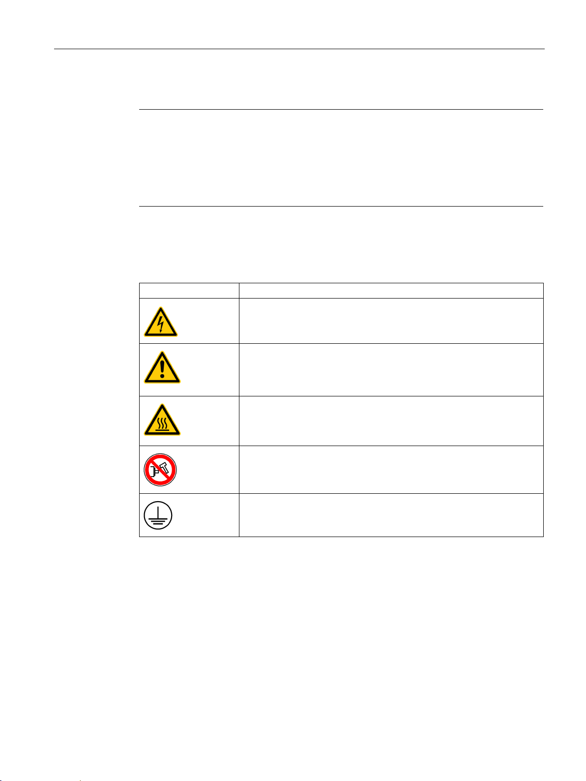
Warning labels
Symbol
Description
Risk of electric shock
Caution
For more information, refer to this manual.
Hot surface
reach up to 65 °C.
No knocking at the shaft
Protective conductor terminal
1.2.1
Residual risks during the operation of electric motors
1.2 Additional safety instructions
-Siemens products. Non-Siemens
ufacturers may be used. Our recommendations are to be seen as
-Siemens products.
Warning labels attached to the motor or drive have the following meanings:
Do not touch any terminals or disassemble cables until the drive has been
disconnected from power for at least five minutes.
Pay attention to the information given on the rating plate and operating
instructions.
Do not touch the heatsink of the drive during operation or within a certain
period since power disconnection because its surface temperature may
Do not exert any shock at the shaft end; otherwise, the encoder may be
damaged.
The motors may be operated only when all protective equipment is used.
Motors may be handled only by qualified and instructed qualified personnel that knows and
observes all safety instructions for the motors that are explained in the associated technical
user documentation.
SINAMICS V90, SIMOTICS S-1FL6
Operating Instructions, 07/2015, 6SL3298-0AV60-0BP0
25

Safety instructions
1.2 Additional safety instructions
When assessing the machine's risk in accordance with the respective local regulations (e.g.,
EC Machinery Directive), the machine manufacturer must take into account the following
residual risks emanating from the control and drive components of a drive system:
1. Unintentional movements of driven machine components during commissioning,
operation, maintenance, and repairs caused by, for example,
– Hardware and/or software errors in the sensors, control system, actuators, and cables
and connections
– Response times of the control system and of the drive
– Operation and/or environmental conditions outside the specification
– Condensation/conductive contamination
– Errors during the assembly, installation, programming and parameterization
– Use of wireless devices/mobile phones in the immediate vicinity of the control system
– External influences/damage
2. In case of failure, unusually high temperatures inside and outside the motor, including
open fire as well as the emission of light, noise, particles, gases, etc. can result, for
example in
– Component failure
– Software errors in converter operation
– Operation and/or environmental conditions outside the specification
– External influences/damage
3. Hazardous shock voltages caused by, for example,
– Component failure
– Influence during electrostatic charging
– Induction of voltages in moving motors
– Operation and/or environmental conditions outside the specification
– Condensation/conductive contamination
– External influences/damage
4. Electrical, magnetic and electromagnetic fields generated in operation that can pose a
risk to people with a pacemaker, implants or metal replacement joints, etc., if they are too
close
5. Release of noxious substances and emissions in the case of improper operation and/or
improper disposal of components
SINAMICS V90, SIMOTICS S-1FL6
26 Operating Instructions, 07/2015, 6SL3298-0AV60-0BP0

2
2.1
Deliverables
2.1.1
Drive components
Component
Illustration
Rated power
(kW)
Outline dimension
(Width x Height x Depth, mm)
Frame size
0.75/1.0
80 x 180 x 200
FSA
1.5/2.0
100 x 180 x 220
FSB
User documentation
Getting Started
English-Chinese bilingual version
When unpacking the drive package, check whether the following components are included.
SINAMICS V90 servo drive
Connectors
Shielding plate
Cable clamp
0.4 60 x 180 x 200 FSAA
3.5/5.0/7.0 140 x 260 x 240 FSC
FSAA/FSA: 4 pieces
FSB/FSC: 2 pieces
for FSAA and FSA
for FSB and FSC
FSAA/FSA: None
FSB/FSC: 1 piece
SINAMICS V90, SIMOTICS S-1FL6
Operating Instructions, 07/2015, 6SL3298-0AV60-0BP0
27
General information
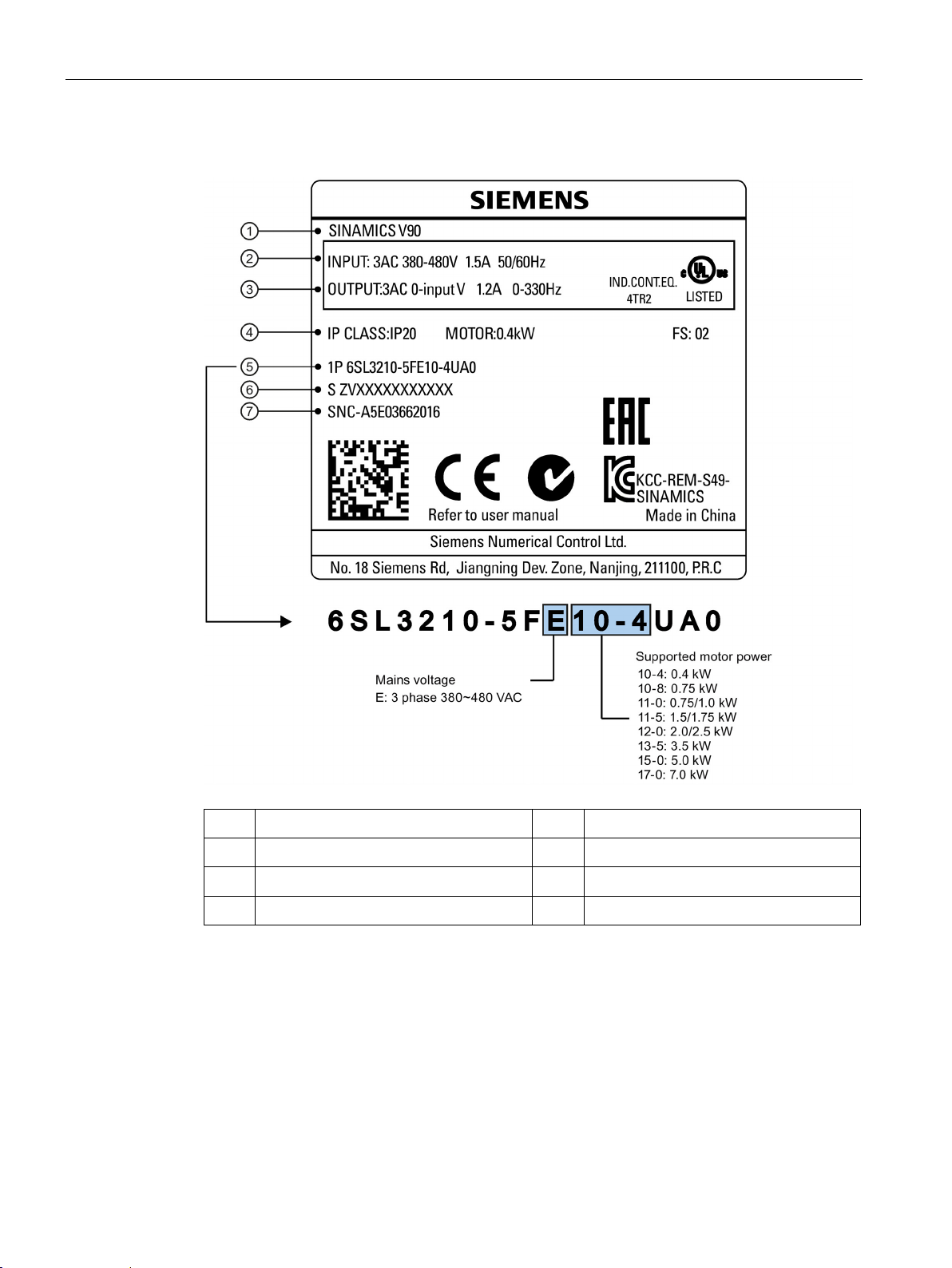
Drive rating plate
①
⑤
②
⑥
④
2.1 Deliverables
Drive name
Power input
③
SINAMICS V90, SIMOTICS S-1FL6
28 Operating Instructions, 07/2015, 6SL3298-0AV60-0BP0
Power output
Rated motor power
⑦
Order number
Product serial number
Part number
General information
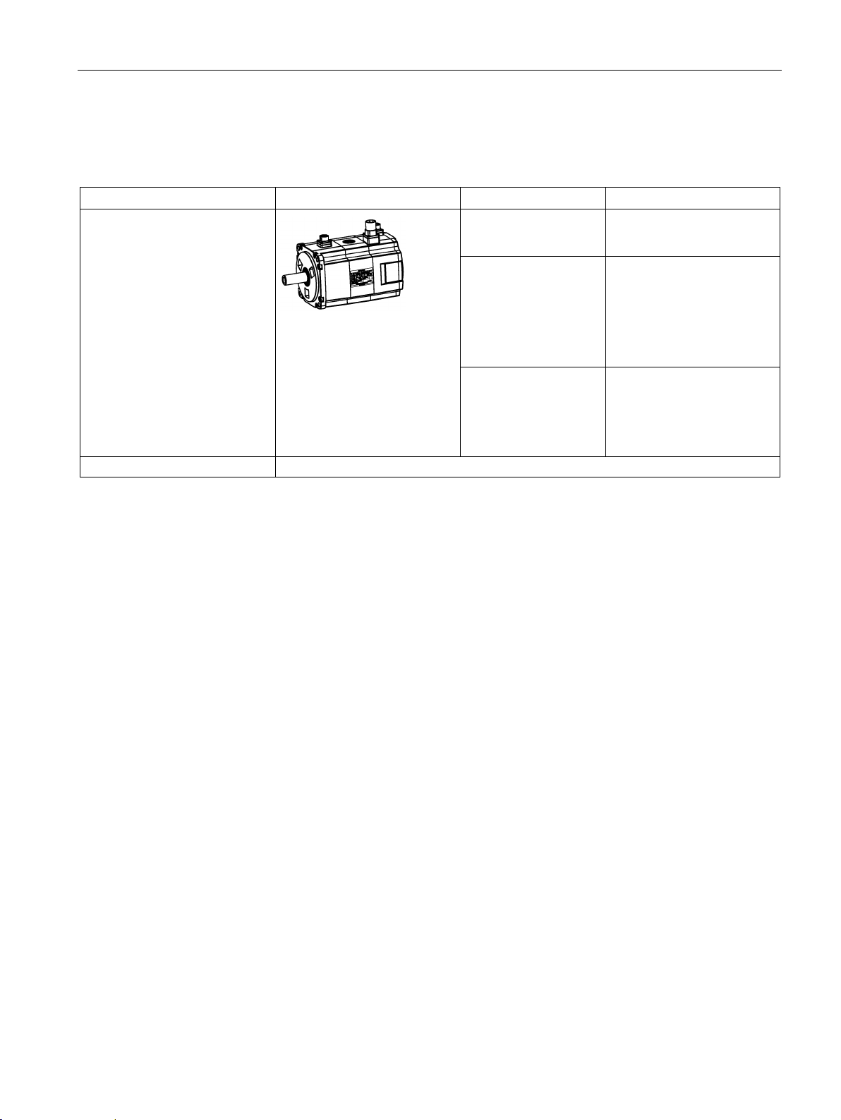
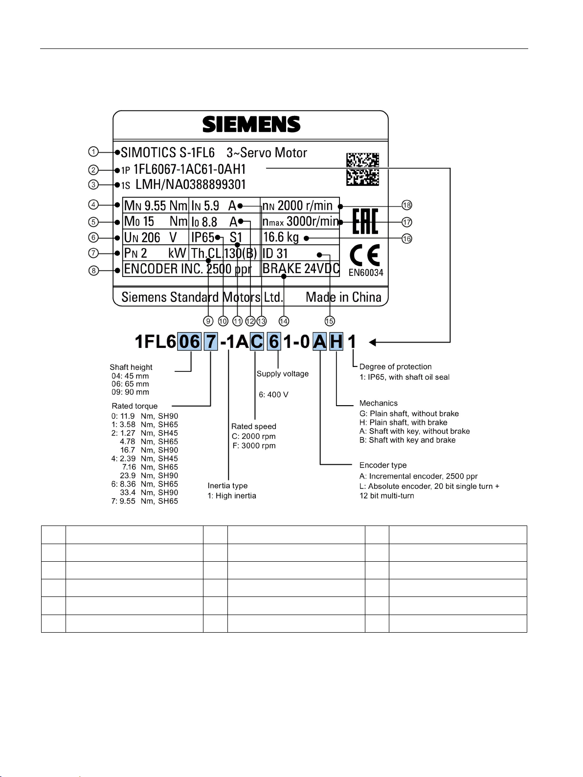
2.1.2
Motor components
Component
Illustration
Rated torque (Nm)
Shaft height (mm)
2.1 Deliverables
When unpacking the motor package, check whether the following components are included.
SIMOTICS S-1FL6 servo motor
User documentation SIMOTICS S-1FL6 Servo Motors Installation Guide
• 1.27
• 2.39
• 3.58
• 4.78
• 7.16
• 8.36
• 9.55
• 11.90
• 16.70
• 23.90
• 33.40
45
65
90
SINAMICS V90, SIMOTICS S-1FL6
Operating Instructions, 07/2015, 6SL3298-0AV60-0BP0
29
General information
Motor rating plate
①
⑦
⑬
②
⑧
⑭
③
⑨
⑮
④
⑩
⑯
⑤
⑪
⑰
⑥
⑫
⑱
2.1 Deliverables
Motor type
Order number
Serial number
Rated torque
Stall torque
Rated voltage
SINAMICS V90, SIMOTICS S-1FL6
30 Operating Instructions, 07/2015, 6SL3298-0AV60-0BP0
Rated power
Encoder type and resolution
Thermal class
Degree of protection
Motor operating mode
Stall current
Rated current
Holding brake
Motor ID
Weight
Maximum speed
Rated speed
 Loading...