

Siemens SINAMICS V60, CPM60.1 Getting Started Manual
Version: 05/2012
Getting Started
SINAMICS V60
Controlled Power Module (CPM60.1)

Table of contents
General information
1.1 System overview ..........................................................
1.2 Safety notes..................................................................
1.3 Identification..................................................................
1.4 Technical data..............................................................
Installation
2.1 Mechanical installation..................................................
Commissioning
3.1.1 Main menu...................................................................
3.1.2 Function menu.............................................................
3.1.3 Setpoints from NC.......................................................
3.1.4 First commissioning.....................................................
3.1.5 System commissioning................................................
3.1 Commissioning............................................................
3.2 Parameter list................................................................
Troubleshooting
EN-3
EN-4
EN-6
EN-8
2.1.1 Mounting the drive.......................................................
2.1.2 Mounting the motor......................................................
2.2 Electrical installation.....................................................
2.3 Interface definition.........................................................
4.1 LED status indicators.....................................................
4.2 Alarms...........................................................................
4.3 Errors during drive self-test...........................................
4.4 Other faults....................................................................
1-NEdetratS gnitteG )1.06MPC( eludoM rewoP dellortnoC 06V SCIMANIS
EN-10
EN-19
EN-25
EN-19
EN-20
EN-22
EN-23
EN-24
EN-10
EN-12
EN-12
EN-16
2.4 Signal sequence example.............................................
EN-18
EN-29
EN-29
EN-32
EN-32
中文版请见第 CHS-1 至 CHS-34 页。
For the Chinese version, see pages CHS-1 to CHS-34.
CPM 的固件(软件)已更新为 V1.7。当前驱动器在缺省状态下较旧版具有更强的动
态性。如需回到旧版工作状态,可将当前缺省值重设为第二缺省值(见 3.1.2 节)。
The firmware (software) in the CPM is already updated to V1.7. Now the performance of the drive in the default status is more dynamic than that of the old version.
If you want the drive to work in the old status, you can change the current default
value to the second default value (see section 3.1.2).

EN-2 SINAMICS V60 Controlled Power Module (CPM60.1) Getting Started
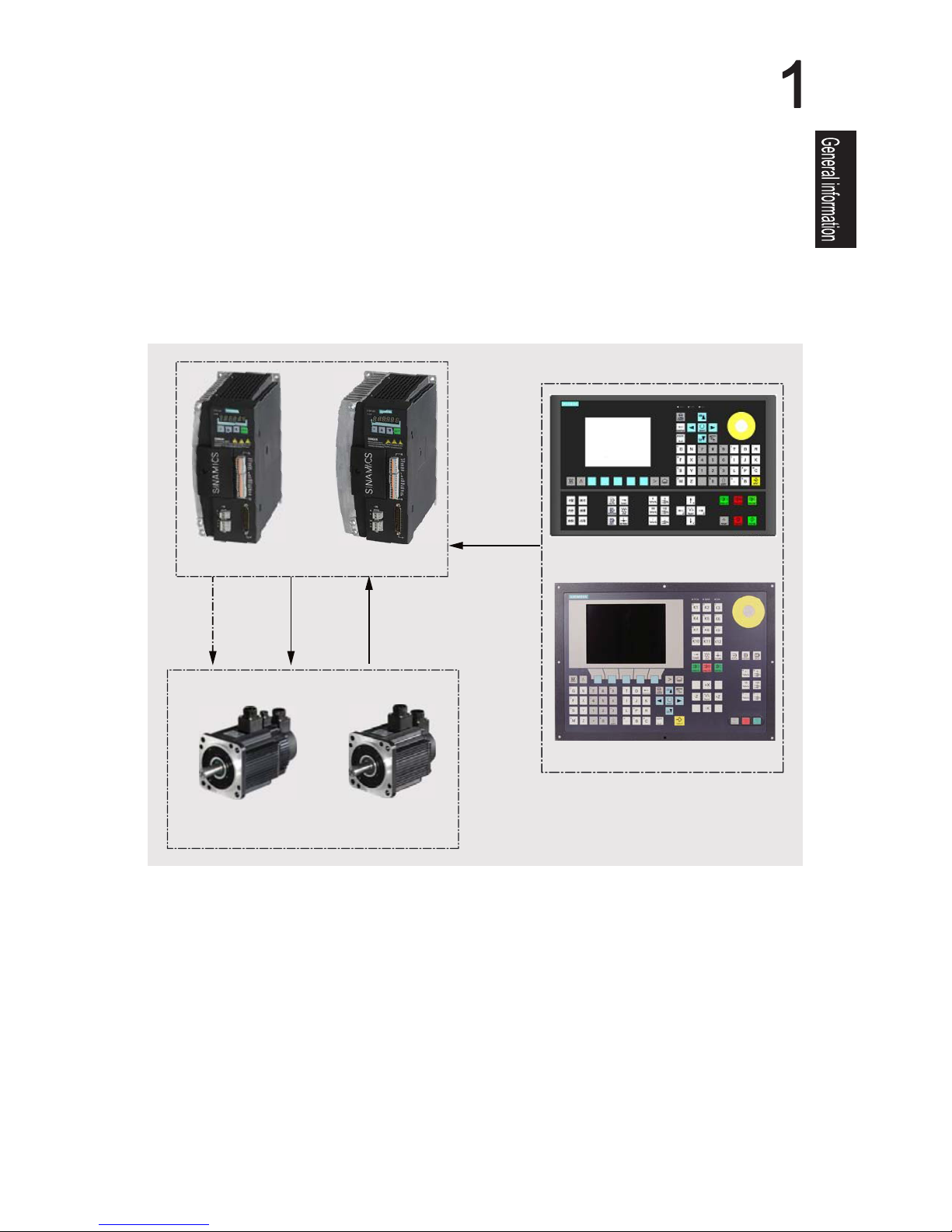
The SINAMICS V60 servo drive system is a new drive system developed by Siemens. It's designed for
use with a Siemens SINUMERIK 801 or SINUMERIK 802S base line numerical controller to control the
operation of a CNC turning or milling machine, and it can also be connected with a Siemens SIMATIC
PLC. Siemens delivers to each customer the whole drive system instead of only one drive device, which
includes: a drive module (CPM60.1, available in 4 A, 6 A, 7 A or 10 A version), an AC servo motor (type
1FL5, with or without a built-in brake and with or without a key ) and all necessary cables (for power,
encoder and brake, with a length of 5m or 10m).
The following picture illustrates possible system configuration
General Information
1.1 System Overview
3-NEdetratS gnitteG )1.06MPC( eludoM rewoP dellortnoC 06V SCIMANIS
or
or
or
Motor with brake Motor without brake
Brake cable
Motor cable
Encoder cable
Setpoint cable
SINUMERIK 801
SINUMERIK 802S base line
4 A/6 A/7 A
10 A
1.2 Safety Notes
EN-4 SINAMICS V60 Controlled Power Module (CPM60.1) Getting Started
Only qualified personnel should be allowed to work on this drive system, and only after
becoming acquainted with all the safety notices regarding installing, connecting,
commissioning, operation and maintenance as set out in this manual. Failure to observe
these notices contained in this manual can result in death, severe personal injury or
considerable damage to property. Without prior authorization, you are not allowed to
perform any modification on the drive.
Deliverables received must be complete and intact. Exercise caution to ensure that you do
not put a damaged device into service. Make sure that the drive, the motor and the cables
received correspond with the specific drive package you ordered from Siemens.
Transport and storage must meet specified environmental conditions.
Do not handle the motor by gripping the connecting cable (motor cable, brake cable or
encoder cable) or the motor shaft.
Risk of fire or electric shock. Use caution to ensure that you do not install the drive and the
motor in an area which is subject to inflammables or combustibles, water or corrosion
hazards.
Do install the drive in a distribution cabinet with an adequate protection level.
Do not install the drive and the motor in a location where it is likely to be exposed to constant
vibrations or physical shocks.
Risk of fire. Make sure that no any foreign body (such as chips of wood or metal, dust, paper
scraps, etc.) falls into the drive or lies on its heatsink.
Keep sufficient clearance between drives, one drive and another device/inner wall of the
cabinet.
Siemens recommends that you tighten the screw on the terminal door of the drive, after you
have completed the installation work.
General
Identification
Transport & Storage
Mechanical installation
WARNING
WARNING
WARNING
CAUTION
CAUTION
NOTICE

SINAMICS V60 Controlled Power Module (CPM60.1) Getting Started EN-5
The drive must have been disconnected from the power supply for at least five minutes
before you perform any wiring to it.
Make sure that all connections are correct and reliable, and the drive and motor are always
properly grounded.
Do suppress radio interference according to EN61800, category C3 (for industrial
environment only).
SINAMICS V60 is an open-loop drive system, so it has no protection against wire breaks.
The drive must connect to the motor directly with no capacitor, inductor or filter, etc.
installed between them.
The mains supply voltage must fall in the range of voltage limits.
It is strictly prohibited to wire the mains input cable to motor terminals U, V, W or to wire a
motor cable to the line input terminals L1, L2, L3.
It is strictly prohibited to wire motor terminals U, V.W on the drive in an incorrect phase
sequence.
If the whole system has to be qualified with CE mark, please use shielded cables for motor
cable, mains input cable and brake cable.
Always install a 380 V three-phase AC isolating transformer at a mains supply network for
protective separation.
Route signal cables separately from power cables and lay them in different cable conduits.
Keep the signal cables a minimum of 10 cm away from the power cables.
Keep cables already connected away from rotating mechanical parts.
Before switching the power on, make sure that the drive system has been reliably installed
and connected, and the mains voltage falls in the permitted voltage limits.
Do not touch the motor shaft when the motor is running. Failure to comply may cause
personal injury.
Ensure that all connections to the SINAMICS V60 drive module have been disconnected
before you perform any voltage test (according to EN60201-1 (VDE0112-1), Article 20.4) for
an electrical device on the machine tool. The drive had passed the insulation test before its
delivery to the customer and doesn't require a second test (for avoiding additional voltage
stress).
The motor brake is only used for brake control over motor start/stop. Unless absolutely
necessary, do not apply it as an emergency stop mechanism.
Only after you have successfully carried out commissioning of the drive system while the
motor operates under dry-run conditions, can you perform commissioning of the drive
system while the motor operates under loaded conditions.
Do not touch the heatsink of the drive, the motor or other high-temperature parts during
equipment running or within a certain period since power disconnection. Failure to comply
may cause personal injury.
Ensure that you do not switch on/off the power frequently. This may cause damage to the
drive system.
The motor rotation direction is determined according to your view from the motor shaft end.
Viewing from the motor shaft end, counterclosewise (CCW) rotation is defined as forward
rotation while clockwise (CW) rotation is defined as reverse rotation.
Electrical installation
Commissioning/Operation
WARNING
WARNING
CAUTION
CAUTION
1.3 Identification
EN-6 SINAMICS V60 Controlled Power Module (CPM60.1) Getting Started
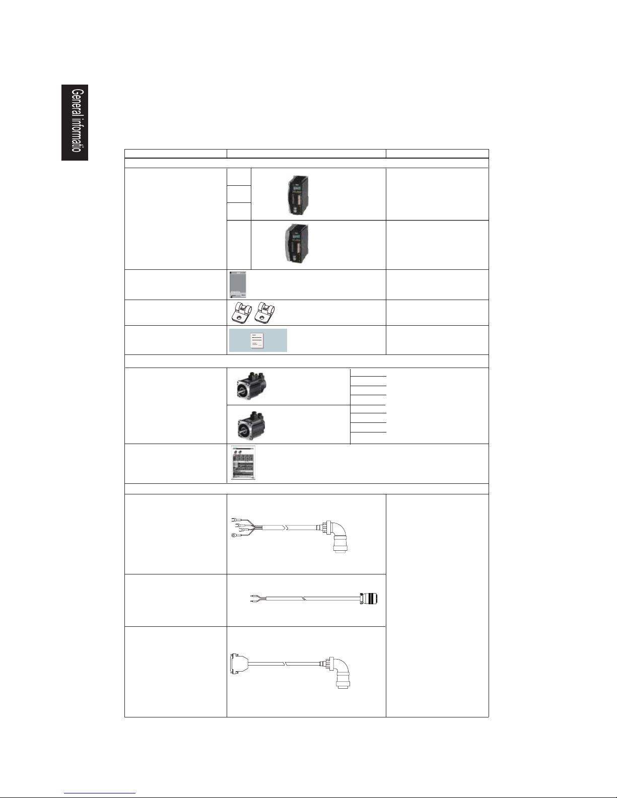
The drive will be always delivered with a complete axis package, including one drive unit
CPM60.1, one motor unit 1FL5. and some necessary cables.
Scope of delivery
Encoder cable (shielded)
Motor cable (unshielded)
Brake cable (unshielded)
Drive side
(to encoder interface X7)
Motor side
(to encoder socket)
4 Nm
4 A
6 A
7 A
10 A
10 Nm
6 Nm
7.7 Nm
4 Nm
10 Nm
6 Nm
7.7 Nm
Refer to the rating plate on
the motor housing for
motor-specific electrical data
Getting started
Warranty card
Cable clamps (2 pieces)
Controlled Power
Module CPM60.1
1FL5 motor
With the brake
Without the brake
Datasheet for 1FL5
motor
For each cable, two lengths
are available for your
selection:
- 5 m
- 10 m
Cables individually packaged
Drive side
(to motor interface U, V, W)
Motor side
(to motor socket)
Drive side
(to motor brake interface X3)
Motor side
(to motor brake socket)
Component Illustration
Remark
--
--
--
Components included in the drive unit package
Components included in the motor unit package
Dimension (W x H x D; in mm):
106 x 226 x 200
Dimension (W x H x D; in mm):
123 x 226 x 200
1FL5 motors have two main
types - with key and without
key. Each type involves motors
with brakes and without brakes.
Applicable to both shielded
and non-shielded cables
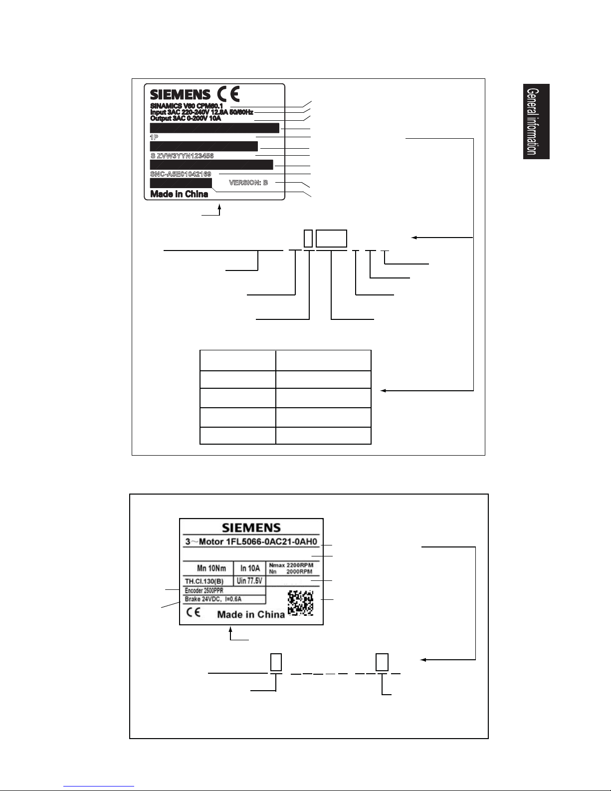
SINAMICS V60 Controlled Power Module (CPM60.1) Getting Started EN-7
Product name
MLFB (order number)
Product serial number
Siemens part number
Rated input voltage, current and frequency
Rated output voltage & current
Hardware version
Bar code
Bar code
Bar code
Bar code
6 S L 3 2 1 0 - 5 C C 2 1 - 0 U A 0
SINAMICS AC Drive,
blocksize, with internal
air cooling
3 AC 220 ... 240 V rated
Multiplier for output current:
1: x 0.1
2: x 1
Rated output current:
4 - 0: 4 A
6 - 0: 6 A
7 - 0: 7 A
1 - 0: 10 A
Unfiltered
Standard
Version
Drive variant/
Rated output current
Order number
4 A
6 A
6SL3210-5CC14-0UA0
6SL3210-5CC16-0UA0
6SL3210-5CC21-0UA0
Drive rating plate
6SL3210-5CC21-0UA0
10 A
6SL3210-5CC17-0UA0
7 A
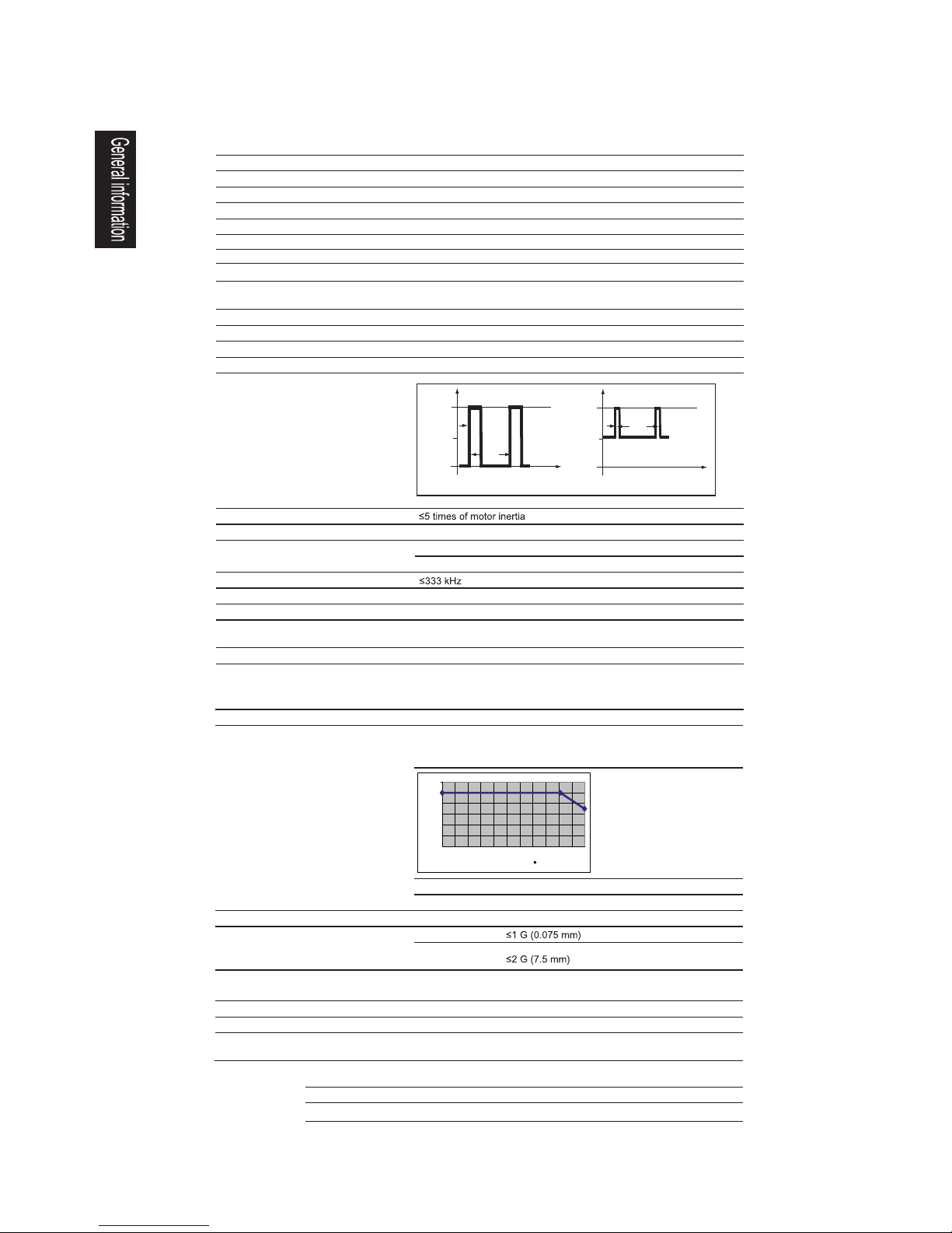
MLFB (order number)
2D-code
(for MLFB and
serial number)
Product serial number
Protection class
Rated
resolution
1 F L 5 0 6 0 - 0 A C 2 1 - 0 A H 0
Rated torque:
0: 4.0 Nm
2: 6.0 Nm
4: 7.7 Nm
6: 10.0 Nm
G: Without key, without brake
H: Without key, with brake
A: With key, without brake
B: With key, with brake
Motor (with brake)
rating plate
Brake
requirements
IPxx
Drive rating plate (example)
Motor rating plate (example)
VERSION: B
S ZVW3YYN123456
SNC-A5E01042169
1P
S 10025AA13LFBZ0001
1.4 Technical data
For technical data of the motor, please refer to the Motor Specification delivered with the motor.
EN-8 SINAMICS V60 Controlled Power Module (CPM60.1) Getting Started
Vibration resistance
Relative humidity
Ambient temperature
< 95%
Operation
Transportation
Storage
-40°C to 70°C
-25°C to 55°C
Operation
Transport &
storage
< 1,000 m above sea level: without power derating;
1,000 to 2,000 m: with power derating (derated to 80%)
Installation altitude
Outline dimensions (W x H x D)
Protection class
Mechanical design
NOTICE
IP20
0 to 45 °C: without power derating (100% load);
45 to 55°C: with power derating (by 0% at 45°C
up to 30% at 55°C ).
Rated voltage: 3 AC 220 V to 240 V
Tolerance: - 15 % ~ + 10 %
50/60 Hz, unregulated DC-Link
Mains supply voltage
Protection functions
Input pulse frequency
Control mode
2. JOG mode
Drive output
Drive input
Encoder
Overcurrent, overvoltage, undervoltage, overload, IGBT overtemperature,
overspeed, encoder abnormal protections, I
2
t detection
TTL encoder 2,500p/r with U, V, W rotor position signal; one zero mark
1. Brake output 2. Servo alarm 3. Servo ready 4. Zero mark
Environmental conditions
Control performance
General performance
Order No.: 6SL3210- 5CC14-0UA0 5CC16-0UA0 5CC17-0UA0 5CC21-0UA0
Applicable load inertia
Overload capability
Setpoint interface
Keys on panel
Display
Axis
Configurable controller
Application field
Rated motor torque
Rated output power
Rated input power
Max. output current
Rated output current
6 Nm
1.2 kW
1.6 kW
2.0 kW
7.7 Nm 10 Nm
4 Nm
tt
I
I
8 A
4 A
6 A
7 A
10 A
12 A
14 A
20 A
0.8 kW
1.4 kW
1.9 kW
2.3 kW
0.9 kW
Turning machines, milling machines, engraving, packaging, printing etc.
SINUMERIK 801, SINUMERIK 802s base line, SIMATIC S7-200 and
SIMATIC S7-1200
Single-axis drive
6-digit, 7-segment LED display, two LED status indicators
4 tact switch keys
Pulse interface
1. Servo enable 2. Alarm cancel
1. Position control (Input mode: pulse + direction signals)
106 x 226 x 200
mm
106 x 226 x 200
mm
106 x 226 x 200
mm
123 x 226 x 200
mm
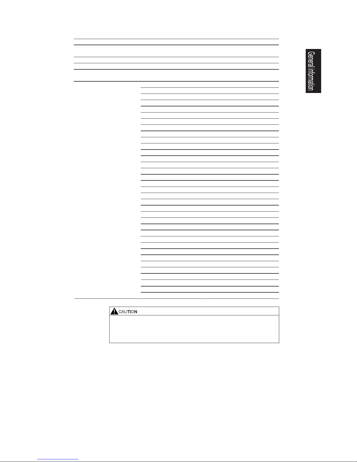
0
20
40
60
80
100
120
0 5 10 15 20 25 30 35 40 45 50 55
Output power
Temperature ( C)
Imax
Imax = 2 x In
In
3s
10s
Imax
In
0.3s
10s
Technical data for CPM60.1 Drive Modules
SINAMICS V60 Controlled Power Module (CPM60.1) Getting Started EN-9
Technical data for transformer
Recommended transformer type 380 V/220 V SG series 3AC isolating transformer
V022/083CA3egatlovylppuS
50/60 Hz
Connection group Y/Y-12
Impedance voltage (Uk%) 4
No-load current (%) For a transformer =< 1.0 kVA, the no-load current < 18%;
For a transformer > 1.0 kVA, the no-load current < 14%.
Possible motor combination Transformer power (apparent power)
AVk0.1mN4
AVk5.1mN6
AVk0.2mN7.7
AVk5.2mN01
AVk5.1mN4+mN4
AVk5.1mN6+mN4
AVk5.1mN7.7+mN4
AVk0.2mN01+mN4
AVk0.2mN6+mN6
AVk0.2mN7.7+mN6
AVk5.2mN01+mN6
AVk0.2mN7.7+mN7.7
AVk5.2mN01+mN7.7
AVk0.3mN01+mN01
4 Nm + 4 Nm + 4 Nm 1.5 kVA
4 Nm + 4 Nm + 6 Nm 1.5 kVA
4 Nm + 4 Nm + 7.7 Nm 2.1 kVA
4 Nm + 4 Nm + 10 Nm 2.0 kVA
4 Nm + 6 Nm + 6 Nm 2.0 kVA
4 Nm + 6 Nm + 7.7 Nm 2.0 kVA
4 Nm + 6 Nm + 10 Nm 2.5 kVA
4 Nm + 7.7 Nm + 7.7 Nm 2.5 kVA
4 Nm + 7.7 Nm + 10 Nm 2.5 kVA
4 Nm + 10 Nm + 10 Nm 3.0 kVA
6 Nm + 6 Nm + 6 Nm 2.0 kVA
6 Nm + 6 Nm + 7.7 Nm 2.0 kVA
6 Nm + 6 Nm + 10 Nm 2.5 kVA
6 Nm + 7.7 Nm + 7.7 Nm 2.5 kVA
6 Nm + 7.7 Nm + 10 Nm 2.5 kVA
7.7 Nm + 7.7 Nm + 7.7 Nm 2.5 kVA
Power selection (for standard
turning/milling machines)
7.7 Nm + 7.7 Nm + 10 Nm 3.0 kVA
6 Nm + 10 Nm + 10 Nm 3.0 kVA
7.7 Nm + 10 Nm + 10 Nm 3.0 kVA
10 Nm + 10 Nm + 10 Nm 3.5 kVA
CAUTION
To reduce the risk of electric shock, interference from power supply and electromagnetic
field, an isolating transformer is necessary for the 3AC 380V mains system.
The customer may select the right transformer with reference to the table above
(Determine the right transformer power based on desired motor combinations)
2
2.1 Mechanical Installation
2.1.1 Mounting the drive
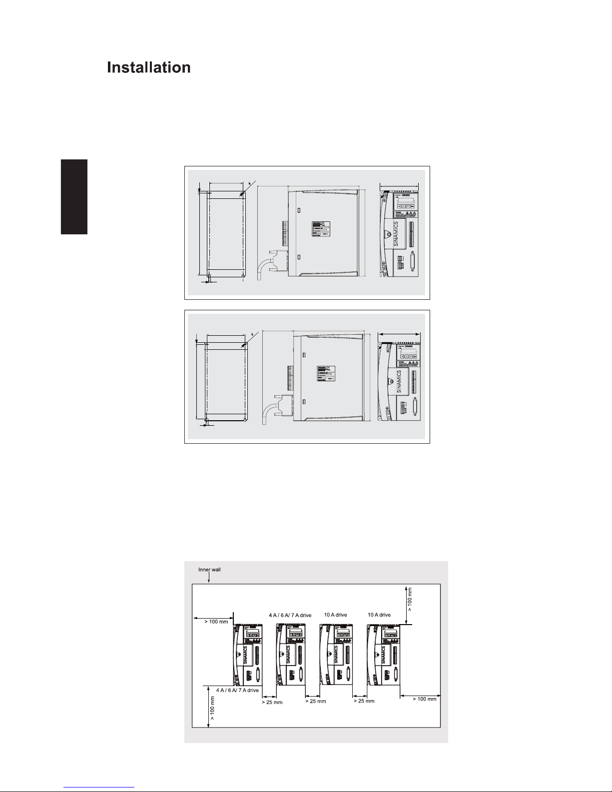
Drill pattern and outline dimensions
Mounting method
Minimum mounting clearance
EN-10 SINAMICS V60 Controlled Power Module (CPM60.1) Getting Started
Installation
You mount the drive with four M5 screws to the inner wall of the cabinet. Note that the drive
must be mounted vertically to the cabinet wall, with the ventilation openings of the drive
pointing upwards. The screw tightening torque of the drive must be no more than 2.0 Nm.
To ensure sufficient heat dissipation, please observe the requirements for minimum
clearance between drives, one drive and another device/inner wall of the cabinet, as
illustrated in the picture below:
93
215
5.5
5.5
2- 5.5
106
RDY / JOG
ERR
80
185
226
215
5.5
110
2- 5.5
5.5
123
RDY/ JOG
ERR
80
185
226
4 A/ 6 A / 7A versions
10 A version
 Loading...