

Siemens SINAMICS V20 Series Easy Start Manual
Siemens V20 Frequency Inverter
Easy Start Guide
L1 L2/N L3
DANGER
RISK OF ELECTRIC
SHOCK! HAZARDOUS VOLTAGE PRESENT FOR
UP TO 5 MINUTES AFTER DISCONNECTION
FROM POWER SUPPLY! SEE INSTRUCTIONS!
10V
AI 1
AI 2
AO 1
UV
DI 1
DI 2
DI 3
DI 4
0V
P+
N–
DI C
24V
0V
W DC- DC+
D0 1+
DO 1-
DO2
NC
DO2
NO
DO2
C
The Siemens V20 Frequency Inverter range is
available to order from inverterdrive.com
This guide is intended to compliment the user manual provided by the manufacturer.
It is provided as a basic introduction to the product for Inverter Drive Supermarket customers.
It should not be used as a replacement for the manual issued by the manufacturer.
This product is not a safety device. All safety considerations including but not
limited to Emergency Stop provision should be assessed separately and are
outside the scope of this guide.
Issue 1
20160509

Easy Start Guide
Siemens V20 Series Inverter
Contents
Page 1
Page 2
Page 3
Page 4
Page 5
Page 6
Page 7
Page 8
Page 9
Contents
Power and Motor Connections (Single Phase)
Power and Motor Connections (Three Phase)
Motor Connections - Star and Delta
Parameters - Overview
Parameters to set before use
How to set a Parameter value
How to Operate the Inverter from the keypad
How to connect and configure a Potentiometer
for remote speed control
How to connect and configure a Run Forward or
Run Reverse switch
Page 10
Page 11
Page 12
This guide has been produced by The Inverter Drive Supermarket Ltd.
All content, including but not limited to graphics, text and procedures copyright The Inverter©
Drive Supermarket and must not be reproduced or altered without prior written permission.
How to connect and configure a Run/Stop switch
with Forward/Reverse selection
How to configure “3-Wire” control with Run/Stop
pushbuttons and Forward/Reverse selection
How to Reset the Inverter to Factory Defaults
Page 1
Easy Start Guide
Siemens V20 Series Inverter
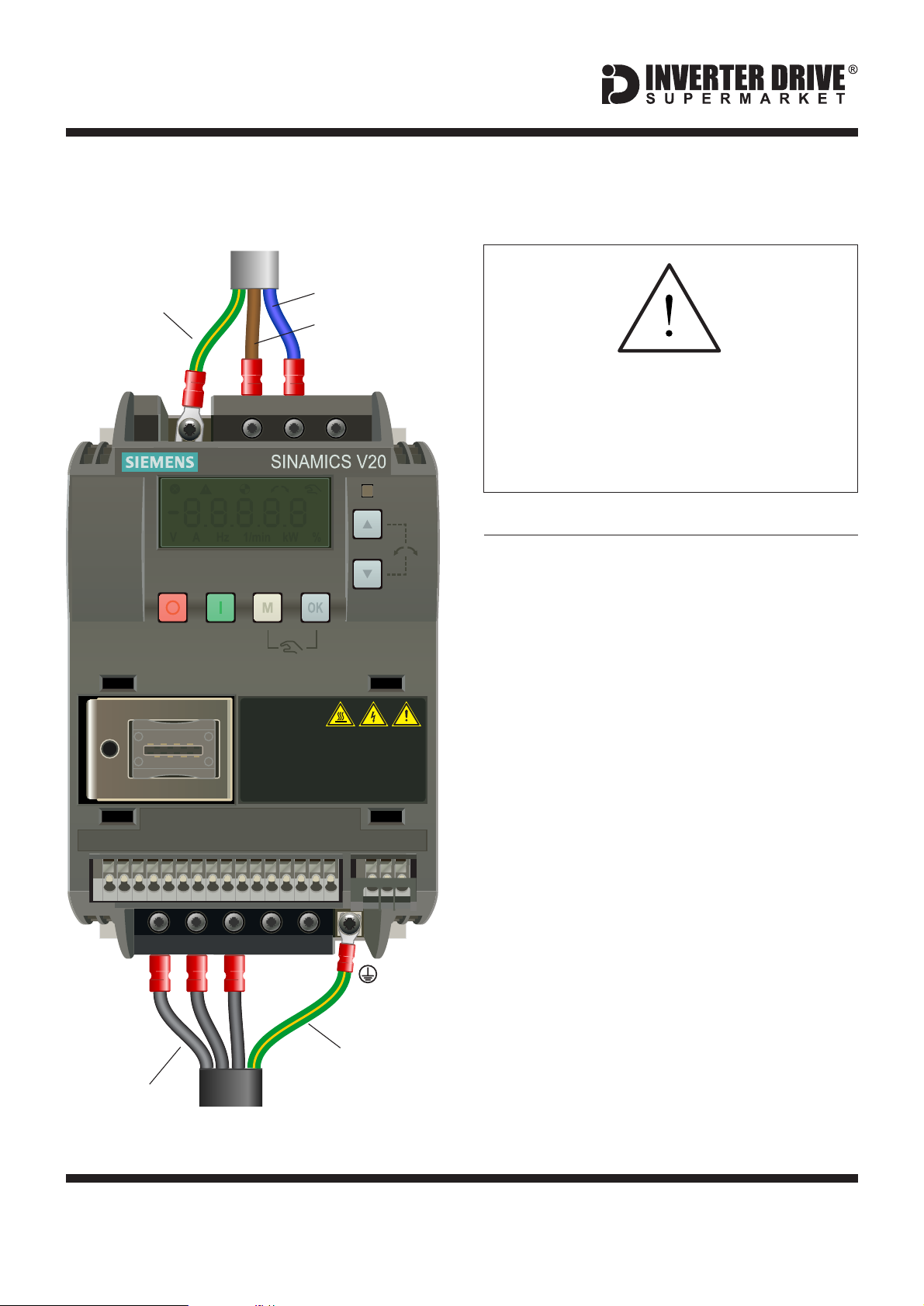
1. Power and Motor Connections (Single Phase)
SUPPLY
Earth
PE
Neutral
Live
L1 L2/N L3
DANGER
RISK OF ELECTRIC
SHOCK! HAZARDOUS VOLTAGE PRESENT FOR
UP TO 5 MINUTES AFTER DISCONNECTION
FROM POWER SUPPLY! SEE INSTRUCTIONS!
Before commencing, confirm that the
Inverter and all cables are completely
isolated from the power supply, have
been isolated for at least 5 minutes and
that the motor is not turning.
Notes:
The illustration on the left is based on the
smaller 230V Single Phase frame size model
(to 0.75kW). The terminal layout for larger
frame sizes is similar.
The order of the three motor phases
determines the direction the motor turns.
Use screened cable between the Inverter and
Motor. To minimise electromagnetic
interference, ensure the cable screen is
grounded.
10V
AI 1
AI 2
AO 1
UV
DI 1
DI 2
DI 3
DI 4
0V
P+
N–
DI C
24V
0V
W DC- DC+
D0 1+
DO 1-
DO2
NC
DO2
NO
DO2
C
Earth
Phases
MOTOR
This guide has been produced by The Inverter Drive Supermarket Ltd.
All content, including but not limited to graphics, text and procedures copyright The Inverter©
Drive Supermarket and must not be reproduced or altered without prior written permission.
Page 2
Easy Start Guide
Siemens V20 Series Inverter
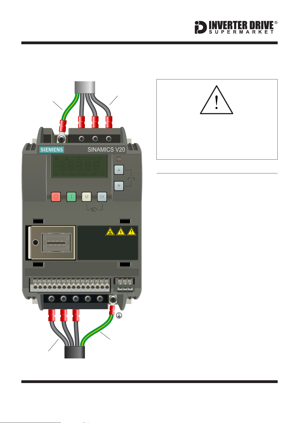
2. Power and Motor Connections (Three Phase)
SUPPLY
Phases
Earth
10V
AI 1
AI 2
PE
AO 1
Before commencing, confirm that the
L1 L2/N L3
Inverter and all cables are completely
isolated from the power supply, have
been isolated for at least 5 minutes and
that the motor is not turning.
Notes:
The illustration on the left is based on the
smaller 400V Three Phase frame size model
(to 0.75kW). The terminal layout for larger
frame sizes is similar.
The order of the three supply phases is
unimportant.
DANGER
RISK OF ELECTRIC
SHOCK! HAZARDOUS VOLTAGE PRESENT FOR
UP TO 5 MINUTES AFTER DISCONNECTION
FROM POWER SUPPLY! SEE INSTRUCTIONS!
The order of the three motor phases
determines the direction the motor turns.
Use screened cable between the Inverter and
Motor. To minimise electromagnetic
DI 1
DI 2
DI 3
DI 4
0V
P+
N–
DI C
24V
0V
D0 1+
DO2
DO 1-
NC
DO2
NO
DO2
C
interference, ensure the cable screen is
grounded.
UV
W DC- DC+
Earth
Phases
MOTOR
This guide has been produced by The Inverter Drive Supermarket Ltd.
All content, including but not limited to graphics, text and procedures copyright The Inverter©
Drive Supermarket and must not be reproduced or altered without prior written permission.
Page 3
 Loading...