

Siemens SINAMICS V20 Operating Instructions Manual

SINAMICS V20 Inverter
___________________
___________________
___________________
___________________
___________________
___________________
___________________
___________________
___________________
___________________
___________________
SINAMICS
SINAMICS V20 Inverter
Operating Instructions
09/2014
Preface
Safety instructions
1
Introduction
2
Mechanical installation
3
Electrical installation
4
Commissioning
5
Communicating with the PLC
6
Parameter list
7
Faults and alarms
8
Technical specifications
A
Options and spare parts
B
A5E34559884

Legal information
Warning notice system
DANGER
will
WARNING
may
CAUTION
NOTICE
Qualified Personnel
personnel qualified
Proper use of Siemens products
WARNING
Trademarks
Disclaimer of Liability
This manual contains notices you have to observe in order to ensure your personal safety, as well as to prevent
damage to property. The notices referring to your personal safety are highlighted in the manual by a safety alert
symbol, notices referring only to property damage have no safety alert symbol. These notices shown below are
graded according to the degree of danger.
indicates that death or severe personal injury
indicates that death or severe personal injury
indicates that minor personal injury can result if proper precautions are not taken.
indicates that property damage can result if proper precautions are not taken.
If more than one degree of danger is present, the warning notice representing the highest degree of danger will
be used. A notice warning of injury to persons with a safety alert symbol may also include a warning relating to
property damage.
result if proper precautions are not taken.
result if proper precautions are not taken.
The product/system described in this documentation may be operated only by
task in accordance with the relevant documentation, in particular its warning notices and safety instructions.
Qualified personnel are those who, based on their training and experience, are capable of identifying risks and
avoiding potential hazards when working with these products/systems.
Note the following:
Siemens products may only be used for the applications described in the catalog and in the relevant technical
documentation. If products and components from other manufacturers are used, these must be recommended
or approved by Siemens. Proper transport, storage, installation, assembly, commissioning, operation and
maintenance are required to ensure that the products operate safely and without any problems. The permissible
ambient conditions must be complied with. The information in the relevant documentation must be observed.
All names identified by ® are registered trademarks of Siemens AG. The remaining trademarks in this publication
may be trademarks whose use by third parties for their own purposes could violate the rights of the owner.
We have reviewed the contents of this publication to ensure consistency with the hardware and software
described. Since variance cannot be precluded entirely, we cannot guarantee full consistency. However, the
information in this publication is reviewed regularly and any necessary corrections are included in subsequent
editions.
for the specific
Siemens AG
Industry Sector
Postfach 48 48
90026 NÜRNBERG
GERMANY
A5E34559884
Ⓟ 10/2014 Subject to change
Copyright © Siemens AG 2014.
All rights reserved

Preface
Purpose of this manual
SINAMICS V20 user documentation components
Document
Content
Available languages
This manual provides you with information about the proper installation, commissioning,
operation, and maintenance of SINAMICS V20 inverters.
Operating Instructions (this manual) English
Chinese
French
German
Italian
Korean
Portuguese
Spanish
Getting Started Describes how you install, operate, and per-
form basic commissioning of the SINAMICS
V20 inverter
Product Information Describes how you install and operate the
following options or spare parts:
• Parameter Loaders
• Dynamic Braking Modules
• External Basic Operator Panels (BOPs)
• BOP Interface Modules
• Shield Connection Kits
• Replacement Fans
English
Chinese
French
German
Italian
Korean
Portuguese
Spanish
English
Chinese
SINAMICS V20 Inverter
Operating Instructions, 09/2014, A5E34559884
3

Preface
Technical support
Country
Hotline
China +86 400 810 4288
France +33 0821 801 122
Germany +49 (0) 911 895 7222
Italy +39 (02) 24362000
Brazil +55 11 3833 4040
India +91 22 2760 0150
Korea +82 2 3450 7114
Turkey +90 (216) 4440747
United States of America +1 423 262 5710
Further service contact information: Support contacts
(http://support.automation.siemens.com/WW/view/en/16604999)
SINAMICS V20 Inverter
4 Operating Instructions, 09/2014, A5E34559884

Table of contents
Preface ................................................................................................................................................... 3
1 Safety instructions ................................................................................................................................... 9
2 Introduction ........................................................................................................................................... 21
3 Mechanical installation .......................................................................................................................... 25
4 Electrical installation.............................................................................................................................. 37
5 Commissioning ..................................................................................................................................... 49
1.1 Fundamental safety instructions ............................................................................................... 9
1.1.1 General safety instructions ....................................................................................................... 9
1.1.2 Safety instructions for electromagnetic fields (EMF) .............................................................. 13
1.1.3 Handling electrostatic sensitive devices (ESD) ...................................................................... 13
1.1.4 Industrial security .................................................................................................................... 14
1.1.5 Residual risks of power drive systems .................................................................................... 15
1.2 Additional safety instructions .................................................................................................. 17
2.1 Components of the inverter system ........................................................................................ 21
2.2 Inverter rating plate ................................................................................................................. 23
3.1 Mounting orientation and clearance ........................................................................................ 25
3.2 Cabinet panel mounting (frame sizes A to E) ......................................................................... 26
3.3 SINAMICS V20 Flat Plate variant ........................................................................................... 28
3.4 Push-through mounting (frame sizes B to E) .......................................................................... 30
3.5 DIN rail mounting (frame sizes A to B) ................................................................................... 33
4.1 Typical system connections .................................................................................................... 37
4.2 Terminal description ................................................................................................................ 40
4.3 EMC-compliant installation ..................................................................................................... 45
4.4 EMC-compliant cabinet design ............................................................................................... 47
5.1 The built-in Basic Operator Panel (BOP) ................................................................................ 49
5.1.1 Introduction to the built-in BOP ............................................................................................... 49
5.1.2 Inverter menu structure ........................................................................................................... 51
5.1.3 Viewing inverter status ............................................................................................................ 53
5.1.4 Editing parameters .................................................................................................................. 53
5.1.5 Screen displays ....................................................................................................................... 56
5.1.6 LED states .............................................................................................................................. 58
5.2 Checking before power-on ...................................................................................................... 58
5.3 Setting the 50/60 Hz selection menu ...................................................................................... 59
5.4 Starting the motor for test run ................................................................................................. 60
5.5 Quick commissioning .............................................................................................................. 60
SINAMICS V20 Inverter
Operating Instructions, 09/2014, A5E34559884
5

Table of contents
6 Communicating with the PLC ............................................................................................................... 133
7 Parameter list ...................................................................................................................................... 147
8 Faults and alarms ................................................................................................................................ 281
5.5.1 Quick commissioning through the setup menu ...................................................................... 60
5.5.1.1 Structure of the setup menu ................................................................................................... 60
5.5.1.2 Setting motor data .................................................................................................................. 62
5.5.1.3 Setting connection macros ..................................................................................................... 63
5.5.1.4 Setting application macros ..................................................................................................... 75
5.5.1.5 Setting common parameters .................................................................................................. 78
5.5.2 Quick commissioning through the parameter menu .............................................................. 79
5.6 Function commissioning ........................................................................................................ 81
5.6.1 Overview of inverter functions ................................................................................................ 81
5.6.2 Commissioning basic functions .............................................................................................. 83
5.6.2.1 Selecting the stop mode ........................................................................................................ 83
5.6.2.2 Running the inverter in JOG mode ........................................................................................ 86
5.6.2.3 Setting the voltage boost ....................................................................................................... 87
5.6.2.4 Setting the PID controller ....................................................................................................... 89
5.6.2.5 Setting the braking function ................................................................................................... 91
5.6.2.6 Setting the ramp time ........................................................................................................... 100
5.6.2.7 Setting the Imax controller ................................................................................................... 102
5.6.2.8 Setting the Vdc controller ..................................................................................................... 104
5.6.2.9 Setting the load torque monitoring function ......................................................................... 105
5.6.3 Commissioning advanced functions .................................................................................... 107
5.6.3.1 Starting the motor in super torque mode ............................................................................. 107
5.6.3.2 Starting the motor in hammer start mode ............................................................................ 109
5.6.3.3 Starting the motor in blockage clearing mode ..................................................................... 111
5.6.3.4 Running the inverter in economy mode ............................................................................... 113
5.6.3.5 Setting the UL508C-compliant motor overtemperature protection ...................................... 114
5.6.3.6 Setting the free function blocks (FFBs) ................................................................................ 115
5.6.3.7 Setting the flying start function ............................................................................................. 116
5.6.3.8 Setting the automatic restart function .................................................................................. 117
5.6.3.9 Running the inverter in frost protection mode ...................................................................... 118
5.6.3.10 Running the inverter in condensation protection mode ....................................................... 119
5.6.3.11 Running the inverter in sleep mode ..................................................................................... 120
5.6.3.12 Setting the wobble generator ............................................................................................... 121
5.6.3.13 Running the inverter in motor staging mode ........................................................................ 122
5.6.3.14 Running the inverter in cavitation protection mode.............................................................. 125
5.6.3.15 Setting the user default parameter set ................................................................................. 126
5.6.3.16 Setting the dual ramp function ............................................................................................. 127
5.6.3.17 Setting the DC coupling function.......................................................................................... 128
5.6.3.18 S
etting high/low overload (HO/LO) mode ............................................................................ 131
5.7 Restoring to defaults ............................................................................................................ 132
6.1 USS communication ............................................................................................................ 133
6.2 MODBUS communication .................................................................................................... 138
7.1 Introduction to parameters ................................................................................................... 147
7.2 Parameter list ....................................................................................................................... 151
8.1 Faults ................................................................................................................................... 281
SINAMICS V20 Inverter
6 Operating Instructions, 09/2014, A5E34559884

Table of contents
A Technical specifications ...................................................................................................................... 293
B Options and spare parts ...................................................................................................................... 301
Index................................................................................................................................................... 341
8.2 Alarms ................................................................................................................................... 289
B.1 Options .................................................................................................................................. 301
B.1.1 Parameter Loader ................................................................................................................. 301
B.1.2 External BOP and BOP Interface Module............................................................................. 305
B.1.3 Connecting cable (external BOP to BOP Interface Module) ................................................ 311
B.1.4 Dynamic braking module ...................................................................................................... 312
B.1.5 Braking resistor ..................................................................................................................... 316
B.1.6 Line reactor ........................................................................................................................... 320
B.1.7 Output reactor ....................................................................................................................... 326
B.1.8 External EMC filter class B ................................................................................................... 330
B.1.9 Shield connection kits ........................................................................................................... 333
B.1.10 Memory card ......................................................................................................................... 336
B.1.11 RS485 termination resistor ................................................................................................... 336
B.1.12 DIN rail mounting kits ............................................................................................................ 336
B.1.13 User documentation .............................................................................................................. 337
B.2 Spare parts - replacement fans ............................................................................................ 337
SINAMICS V20 Inverter
Operating Instructions, 09/2014, A5E34559884
7

Table of contents
SINAMICS V20 Inverter
8 Operating Instructions, 09/2014, A5E34559884
1
1.1
Fundamental safety instructions
1.1.1
General safety instructions
DANGER
Danger to life due to live parts and other energy sources
WARNING
Danger to life through a hazardous voltage when connecting an unsuitable power supply
Death or serious injury can result when live parts are touched.
• Only work on electrical devices when you are qualified for this job.
• Always observe the country-specific safety rules.
Generally, six steps apply when establishing safety:
1. Prepare for shutdown and notify all those who will be affected by the procedure.
2. Disconnect the machine from the supply.
– Switch off the machine.
– Wait until the discharge time specified on the warning labels has elapsed.
– Check that it really is in a no-voltage condition, from phase conductor to phase
conductor and phase conductor to protective conductor.
– Check whether the existing auxiliary supply circuits are de-energized.
– Ensure that the motors cannot move.
3. Identify all other dangerous energy sources, e.g. compressed air, hydraulic systems, or
water.
4. Isolate or neutralize all hazardous energy sources by closing switches, grounding or
short-circuiting or closing valves, for example.
5. Secure the energy sources against switching on again.
6. Ensure that the correct machine is completely interlocked.
After you have completed the work, restore the operational readiness in the inverse
sequence.
Touching live components can result in death or severe injury.
• Only use power supplies that provide SELV (Safety Extra Low Voltage) or PELV-
(Protective Extra Low Voltage) output voltages for all connections and terminals of the
electronics modules.
SINAMICS V20 Inverter
Operating Instructions, 09/2014, A5E34559884
9
Safety instructions
WARNING
Danger to life when live parts are touched on damaged devices
WARNING
Danger to life through electric shock due to unconnected cable shields
WARNING
Danger to life due to electric shock when not grounded
WARNING
Danger to life due to electric shock when opening plug connections in operation
WARNING
Danger to life due to fire spreading if housing is inadequate
1.1 Fundamental safety instructions
Improper handling of devices can cause damage.
For damaged devices, hazardous voltages can be present at the enclosure or at exposed
components; if touched, this can result in death or severe injury.
• Ensure compliance with the limit values specified in the technical data during transport,
storage and operation.
• Do not use any damaged devices.
Hazardous touch voltages can occur through capacitive cross-coupling due to unconnected
cable shields.
• As a minimum, connect cable shields and the conductors of power cables that are not
used (e.g. brake cores) at one end at the grounded housing potential.
For missing or incorrectly implemented protective conductor connection for devices with
protection class I, high voltages can be present at open, exposed parts, which when
touched, can result in death or severe injury.
• Ground the device in compliance with the applicable regulations.
When opening plug connections in operation, arcs can result in severe injury or death.
• Only open plug connections when the equipment is in a no-voltage state, unless it has
been explicitly stated that they can be opened in operation.
Fire and smoke development can cause severe personal injury or material damage.
• Install devices without a protective housing in a metal control cabinet (or protect the
device by another equivalent measure) in such a way that contact with fire is prevented.
• Ensure that smoke can only escape via controlled and monitored paths.
SINAMICS V20 Inverter
10 Operating Instructions, 09/2014, A5E34559884
Safety instructions
WARNING
Danger to life through unexpected movement of machines when using mobile wireless
devices or mobile phones
WARNING
Danger to life due to the motor catching fire in the event of insulation overload
WARNING
Danger to life due to fire if overheating occurs because of insufficient ventilation clearances
WARNING
Danger of an accident occurring due to missing or illegible warning labels
1.1 Fundamental safety instructions
Using mobile wireless devices or mobile phones with a transmit power > 1 W closer than
approx. 2 m to the components may cause the devices to malfunction, influence the
functional safety of machines therefore putting people at risk or causing material damage.
• Switch the wireless devices or mobile phones off in the immediate vicinity of the
components.
There is higher stress on the motor insulation through a ground fault in an IT system. If the
insulation fails, it is possible that death or severe injury can occur as a result of smoke and
fire.
• Use a monitoring device that signals an insulation fault.
• Correct the fault as quickly as possible so the motor insulation is not overloaded.
Inadequate ventilation clearances can cause overheating of components with subsequent
fire and smoke. This can cause severe injury or even death. This can also result in
increased downtime and reduced service lives for devices/systems.
• Ensure compliance with the specified minimum clearance as ventilation clearance for
the respective component.
Missing or illegible warning labels can result in accidents involving death or serious injury.
• Check that the warning labels are complete based on the documentation.
• Attach any missing warning labels to the components, in the national language if
necessary.
• Replace illegible warning labels.
SINAMICS V20 Inverter
Operating Instructions, 09/2014, A5E34559884
11
Safety instructions
NOTICE
Device damage caused by incorrect voltage/insulation tests
WARNING
Danger to life when safety functions are inactive
Note
Important safety notices for Safety Integrated functions
WARNING
Danger to life or malfunctions of the machine as a result of incorrect or changed
parameterization
1.1 Fundamental safety instructions
Incorrect voltage/insulation tests can damage the device.
• Before carrying out a voltage/insulation check of the system/machine, disconnect the
devices as all converters and motors have been subject to a high voltage test by the
manufacturer, and therefore it is not necessary to perform an additional test within the
system/machine.
Safety functions that are inactive or that have not been adjusted accordingly can cause
operational faults on machines that could lead to serious injury or death.
• Observe the information in the appropriate product documentation before
commissioning.
• Carry out a safety inspection for functions relevant to safety on the entire system,
including all safety-related components.
• Ensure that the safety functions used in your drives and automation tasks are adjusted
and activated through appropriate parameterizing.
• Perform a function test.
• Only put your plant into live operation once you have guaranteed that the functions
relevant to safety are running correctly.
If you want to use Safety Integrated functions, you must observe the safety notices in the
Safety Integrated manuals.
As a result of incorrect or changed parameterization, machines can malfunction, which in
turn can lead to injuries or death.
• Protect the parameterization (parameter assignments) against unauthorized access.
• Respond to possible malfunctions by applying suitable measures (e.g. EMERGENCY
STOP or EMERGENCY OFF).
SINAMICS V20 Inverter
12 Operating Instructions, 09/2014, A5E34559884
Safety instructions
1.1.2
Safety instructions for electromagnetic fields (EMF)
WARNING
Danger to life from electromagnetic fields
1.1.3
Handling electrostatic sensitive devices (ESD)
NOTICE
Damage through electric fields or electrostatic discharge
1.1 Fundamental safety instructions
Electromagnetic fields (EMF) are generated by the operation of electrical power equipment
such as transformers, converters or motors.
People with pacemakers or implants are at a special risk in the immediate vicinity of these
devices/systems.
• Ensure that the persons involved are the necessary distance away (minimum 2 m).
Electrostatic sensitive devices (ESD) are individual components, integrated circuits, modules
or devices that may be damaged by either electric fields or electrostatic discharge.
Electric fields or electrostatic discharge can cause malfunctions through damaged
individual components, integrated circuits, modules or devices.
• Only pack, store, transport and send electronic components, modules or devices in their
original packaging or in other suitable materials, e.g conductive foam rubber of
aluminum foil.
• Only touch components, modules and devices when you are grounded by one of the
following methods:
– Wearing an ESD wrist strap
– Wearing ESD shoes or ESD grounding straps in ESD areas with conductive flooring
• Only place electronic components, modules or devices on conductive surfaces (table
with ESD surface, conductive ESD foam, ESD packaging, ESD transport container).
SINAMICS V20 Inverter
Operating Instructions, 09/2014, A5E34559884
13

Safety instructions
1.1.4
Industrial security
Note
Industrial security
WARNING
Danger as a result of unsafe operating states resulting from software manipulation
1.1 Fundamental safety instructions
Siemens provides products and solutions with industrial security functions that support the
secure operation of plants, solutions, machines, equipment and/or networks. They are
important components in a holistic industrial security concept. With this in mind, Siemens’
products and solutions undergo continuous development. Siemens recommends strongly
that you regularly check for product updates.
For the secure operation of Siemens products and solutions, it is necessary to take suitable
preventive action (e.g. cell protection concept) and integrate each component into a holistic,
state-of-the-art industrial security concept. Third-party products that may be in use should
also be considered. For more information about industrial security, visit Hotspot text
(http://www.siemens.com/industrialsecurity).
To stay informed about product updates as they occur, sign up for a product-specific
newsletter. For more information, visit Hotspot text (http://support.automation.siemens.com).
Software manipulation (e.g. by viruses, Trojan horses, malware, worms) can cause unsafe
operating states to develop in your installation which can result in death, severe injuries
and/or material damage.
• Keep the software up to date.
You will find relevant information and newsletters at this address
(http://support.automation.siemens.com).
• Incorporate the automation and drive components into a holistic, state-of-the-art
industrial security concept for the installation or machine.
You will find further information at this address
(http://www.siemens.com/industrialsecurity).
• Make sure that you include all installed products into the holistic industrial security
concept.
SINAMICS V20 Inverter
14 Operating Instructions, 09/2014, A5E34559884

Safety instructions
1.1.5
Residual risks of power drive systems
1.1 Fundamental safety instructions
The control and drive components of a drive system are approved for industrial and
commercial use in industrial line supplies. Their use in public line supplies requires a
different configuration and/or additional measures.
These components may only be operated in closed housings or in higher-level control
cabinets with protective covers that are closed, and when all of the protective devices are
used.
These components may only be handled by qualified and trained technical personnel who
are knowledgeable and observe all of the safety instructions on the components and in the
associated technical user documentation.
When assessing the machine's risk in accordance with the respective local regulations (e.g.,
EC Machinery Directive), the machine manufacturer must take into account the following
residual risks emanating from the control and drive components of a drive system:
1. Unintentional movements of driven machine components during commissioning,
operation, maintenance, and repairs caused by, for example,
– Hardware and/or software errors in the sensors, control system, actuators, and cables
and connections
– Response times of the control system and of the drive
– Operation and/or environmental conditions outside the specification
– Condensation/conductive contamination
– Parameterization, programming, cabling, and installation errors
– Use of wireless devices/mobile phones in the immediate vicinity of the control system
– External influences/damage
2. In the event of a fault, exceptionally high temperatures, including an open fire, as well as
emissions of light, noise, particles, gases, etc. can occur inside and outside the inverter,
e.g.:
– Component failure
– Software errors
– Operation and/or environmental conditions outside the specification
– External influences/damage
Inverters of the Open Type/IP20 degree of protection must be installed in a metal control
cabinet (or protected by another equivalent measure) such that contact with fire inside
and outside the inverter is not possible.
3. Hazardous shock voltages caused by, for example,
– Component failure
– Influence during electrostatic charging
– Induction of voltages in moving motors
– Operation and/or environmental conditions outside the specification
– Condensation/conductive contamination
– External influences/damage
SINAMICS V20 Inverter
Operating Instructions, 09/2014, A5E34559884
15

Safety instructions
Note
1.1 Fundamental safety instructions
4. Electrical, magnetic and electromagnetic fields generated in operation that can pose a
risk to people with a pacemaker, implants or metal replacement joints, etc., if they are too
close
5. Release of environmental pollutants or emissions as a result of improper operation of the
system and/or failure to dispose of components safely and correctly
The components must be protected against conductive contamination (e.g. by installing them
in a control cabinet with degree of protection IP54 according to IEC 60529 or NEMA 12).
Assuming that conductive contamination at the installation site can definitely be excluded, a
lower degree of cabinet protection may be permitted.
For more information about residual risks of the components in a drive system, see the
relevant sections in the technical user documentation.
SINAMICS V20 Inverter
16 Operating Instructions, 09/2014, A5E34559884
Safety instructions
1.2
Additional safety instructions
General
DANGER
Protective earthing conductor current
WARNING
Safe use of inverters
1.2 Additional safety instructions
The earth leakage current of the SINAMICS V20 inverter may exceed 3.5 mA AC. Due to
this, a fixed earth connection is required and the minimum size of the protective earth
conductor shall comply with the local safety regulations for high leakage current equipment.
The SINAMICS V20 inverter has been designed to be protected by fuses; however, as the
inverter can cause a DC current in the protective earthing conductor, if a Residual Current
Device (RCD) is to be used upstream in the supply, observe the following:
• All SINAMICS V20 single phase AC 230 V inverters (filtered or unfiltered) can be
operated on a type A
• All SINAMICS V20 three phase AC 400 V inverters (unfiltered) can be operated on a
type B(k) 30 mA RCD.
• SINAMICS V20 three phase AC 400 V inverters (filtered) with rated power up to 2.2 kW
can be operated on a type B(k) 30 mA RCD. For inverters with rated power over 3.0 kW,
a type B(k) 300 mA RCD can be used.
1)
To use a type A RCD, the regulations in this FAQ must be followed: Siemens Web site
(http://support.automation.siemens.com/WW/view/en/49232264)
1)
30 mA or type B(k) 30 mA RCD.
Any unauthorized modifications of the equipment are not allowed.
Protection in case of direct contact by means of voltages < 60 V (PELV = Protective Extra
Low Voltage according to EN 61800-5-1) is only permissible in areas with equipotential
bonding and in dry indoor rooms. If these conditions are not fulfilled, other protective
measures against electric shock must be applied, for example, protective insulation.
Install the inverter on a metal mounting plate in a control cabinet. The mounting plate has to
be unpainted and with a good electrical conductivity.
It is strictly prohibited for any mains disconnection to be performed on the motor-side of the
system, if the inverter is in operation and the output current is not zero.
SINAMICS V20 Inverter
Operating Instructions, 09/2014, A5E34559884
17
Safety instructions
Installation
WARNING
Requirements for United States / Canadian installations (UL/cUL)
WARNING
Branch-circuit protective device
CAUTION
Cable connection
1.2 Additional safety instructions
Suitable for use on a circuit capable of delivering not more than 40000 rms Symmetrical
Amperes, 480 Vac maximum for 400 V variants of inverters or 240 Vac maximum for 230 V
variants of inverters, when protected by UL/cUL-certified Class J fuses or type E
combination motor controllers. For each frame size A to E, use 75 °C copper wire only.
This equipment is capable of providing internal motor overload protection according to
UL508C. In order to comply with UL508C, parameter P0610 must not be changed from its
factory setting of 6.
For Canadian (cUL) installations the inverter mains supply must be fitted with any external
recommended suppressor with the following features:
• Surge-protective devices; device shall be a Listed Surge-protective device (Category
code VZCA and VZCA7)
• Rated nominal voltage 480/277 VAC (for 400 V variants) or 240 VAC (for 230 V
variants), 50/60 Hz, three phase (for 400 V variants) or single phase (for 230V variants)
• Clamping voltage VPR = 2000 V (for 400 V variants) / 1000 V (for 230 V variants), IN =
3 kA min, MCOV = 508 VAC (for 400 V variants) / 264 VAC (for 230V variants), SCCR =
40 kA
• Suitable for Type 1 or Type 2 SPD application
• Clamping shall be provided between phases and also between phase and ground
The opening of the branch-circuit protective device may be an indication that a fault current
has been interrupted. To reduce the risk of fire or electric shock, current-carrying parts and
other components of the controller should be examined and the controller should be
replaced if damaged. If burnout of the current element of an overload relay occurs, the
complete overload relay must be replaced.
Integral solid state short circuit protection does not provide branch circuit protection. Branch
circuit protection must be provided in accordance with the National Electrical Code and any
additional local codes.
Separate the control cables from the power cables as much as possible.
Keep the connecting cables away from rotating mechanical parts.
SINAMICS V20 Inverter
18 Operating Instructions, 09/2014, A5E34559884
Safety instructions
NOTICE
Motor supply voltage
Inverter mounting
Operation
WARNING
Use of braking resistor
WARNING
Hot surface
CAUTION
Use of fuses
Repair
WARNING
Repair and replacement of equipment
1.2 Additional safety instructions
Make sure that the motor is configured for the correct supply voltage.
Mount the inverter vertically to a flat and non-combustible surface.
If an unsuitable braking resistor is used, this could result in a fire and severe damage to
people, property and equipment. Use an appropriate braking resistor and install it correctly.
The temperature of a braking resistor increases significantly during operation. Avoid coming
into direct contact with braking resistors.
During operation and for a short time after switching-off the inverter, the marked surfaces of
the inverter can reach a high temperature. Avoid coming into direct contact with these
surfaces.
This equipment is suitable for use in a power system up to 40,000 symmetrical amperes
(rms), for the maximum rated voltage + 10 % when protected by an appropriate standard
fuse.
Repairs on equipment may only be carried out by Siemens Service, by repair centers
authorized by Siemens or by authorized personnel who are thoroughly acquainted with all
the warnings and operating procedures contained in this manual.
Any defective parts or components must be replaced using parts contained in the relevant
spare parts lists.
Disconnect the power supply before opening the equipment for access.
SINAMICS V20 Inverter
Operating Instructions, 09/2014, A5E34559884
19

Safety instructions
Dismantling and disposal
NOTICE
Inverter disposal
1.2 Additional safety instructions
The packaging of the inverter is re-usable. Retain the packaging for future use.
Easy-to-release screw and snap connectors allow you to break the unit down into its
component parts. You can recycle these component parts, dispose of them in accordance
with local requirements or return them to the manufacturer.
SINAMICS V20 Inverter
20 Operating Instructions, 09/2014, A5E34559884
2
2.1
Components of the inverter system
Three phase AC 400 V variants
Component
Rated output
power
Rated
input
current
Rated
output
current
Output current
at 480 V at
4kHz/40°C
Order number
unfiltered
filtered
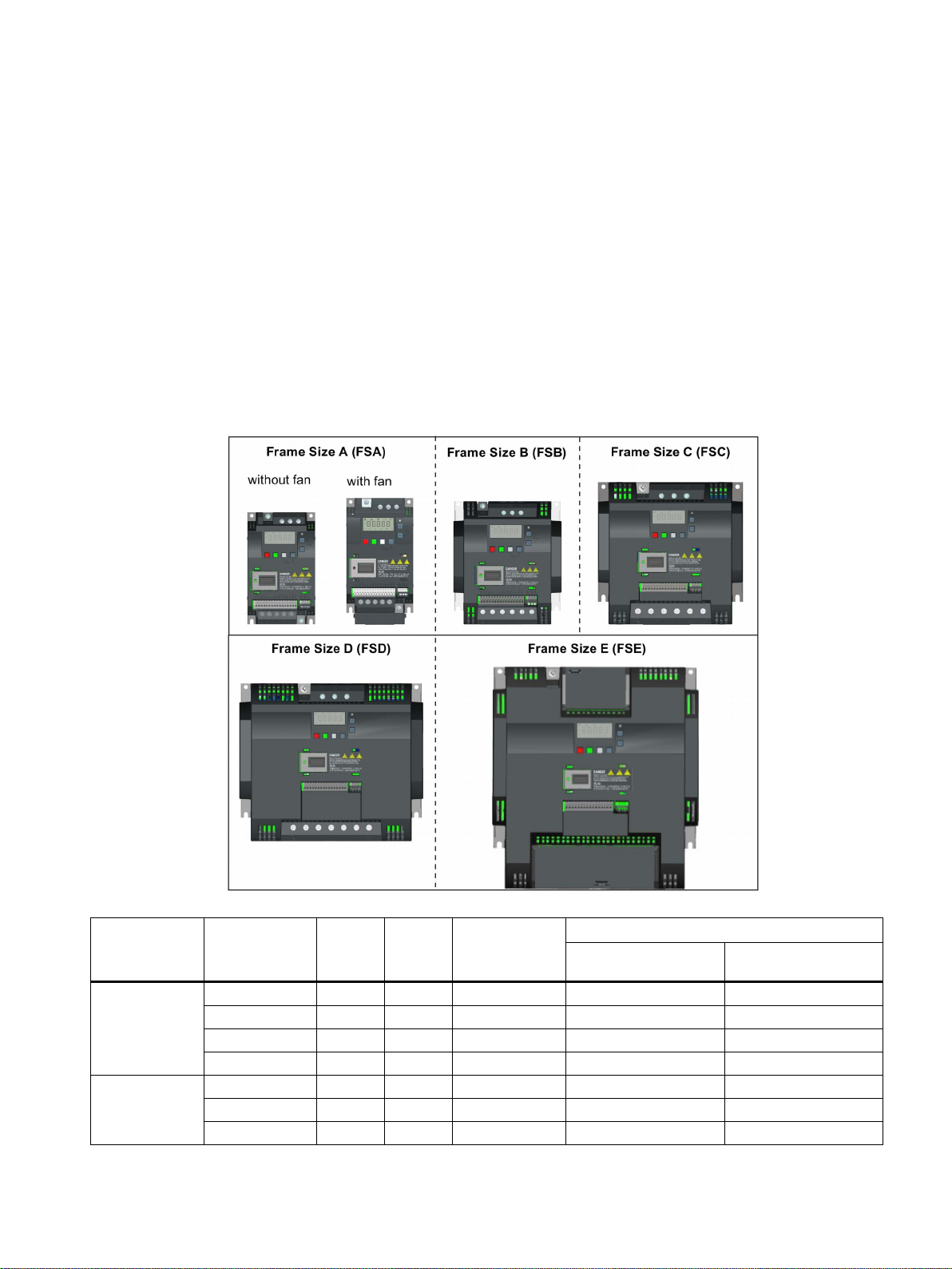
The SINAMICS V20 is a range of inverters designed for controlling the speed of three phase
asynchronous motors.
The three phase AC 400 V inverters are available in five frame sizes.
Frame size A
(without fan)
Frame size A
(with single fan)
SINAMICS V20 Inverter
Operating Instructions, 09/2014, A5E34559884
0.37 kW 1.7 A 1.3 A 1.3 A 6SL3210-5BE13-7UV0 6SL3210-5BE13-7CV0
0.55 kW 2.1 A 1.7 A 1.6 A 6SL3210-5BE15-5UV0 6SL3210-5BE15-5CV0
0.75 kW 2.6 A 2.2 A 2.2 A 6SL3210-5BE17-5UV0 6SL3210-5BE17-5CV0
0.75 kW 1) 2.6 A 2.2 A 2.2 A - 6SL3216-5BE17-5CV0
1.1 kW 4.0 A 3.1 A 3.1 A 6SL3210-5BE21-1UV0 6SL3210-5BE21-1CV0
1.5 kW 5.0 A 4.1 A 4.1 A 6SL3210-5BE21-5UV0 6SL3210-5BE21-5CV0
2.2 kW 6.4 A 5.6 A 4.8 A 6SL3210-5BE22-2UV0 6SL3210-5BE22-2CV0
21
Introduction
Component
Rated output
power
Rated
input
current
Rated
output
current
Output current
at 480 V at
4kHz/40°C
Order number
unfiltered
filtered
parameter settings.
Single phase AC 230 V variants
Component
Rated output
power
Rated input
current
Rated output
current
Order number
unfiltered
filtered
2.1 Components of the inverter system
Frame size B
(with single fan)
Frame size C
3.0 kW 8.6 A 7.3 A 7.3 A 6SL3210-5BE23-0UV0 6SL3210-5BE23-0CV0
4.0 kW 11.3 A 8.8 A 8.24 A 6SL3210-5BE24-0UV0 6SL3210-5BE24-0CV0
5.5 kW 15.2 A 12.5 A 11 A 6SL3210-5BE25-5UV0 6SL3210-5BE25-5CV0
(with single fan)
Frame size D
(with two fans)
7.5 kW 20.7 A 16.5 A 16.5 A 6SL3210-5BE27-5UV0 6SL3210-5BE27-5CV0
11 kW 30.4 A 25 A 21 A 6SL3210-5BE31-1UV0 6SL3210-5BE31-1CV0
15 kW 38.1 A 31 A 31 A 6SL3210-5BE31-5UV0 6SL3210-5BE31-5CV0
Frame size E
(with two fans)
18.5 kW (HO) 2) 45 A 38 A 34 A 6SL3210-5BE31-8UV0 6SL3210-5BE31-8CV0
22 kW (LO) 54 A 45 A 40 A
22 kW (HO) 54 A 45 A 40 A 6SL3210-5BE32-2UV0 6SL3210-5BE32-2CV0
30 kW (LO) 72 A 60 A 52 A
1)
This variant refers to the Flat Plate inverter with a flat plate heatsink.
2)
"HO" and "LO" indicate high overload and low overload respectively. You can set the HO/LO mode through relevant
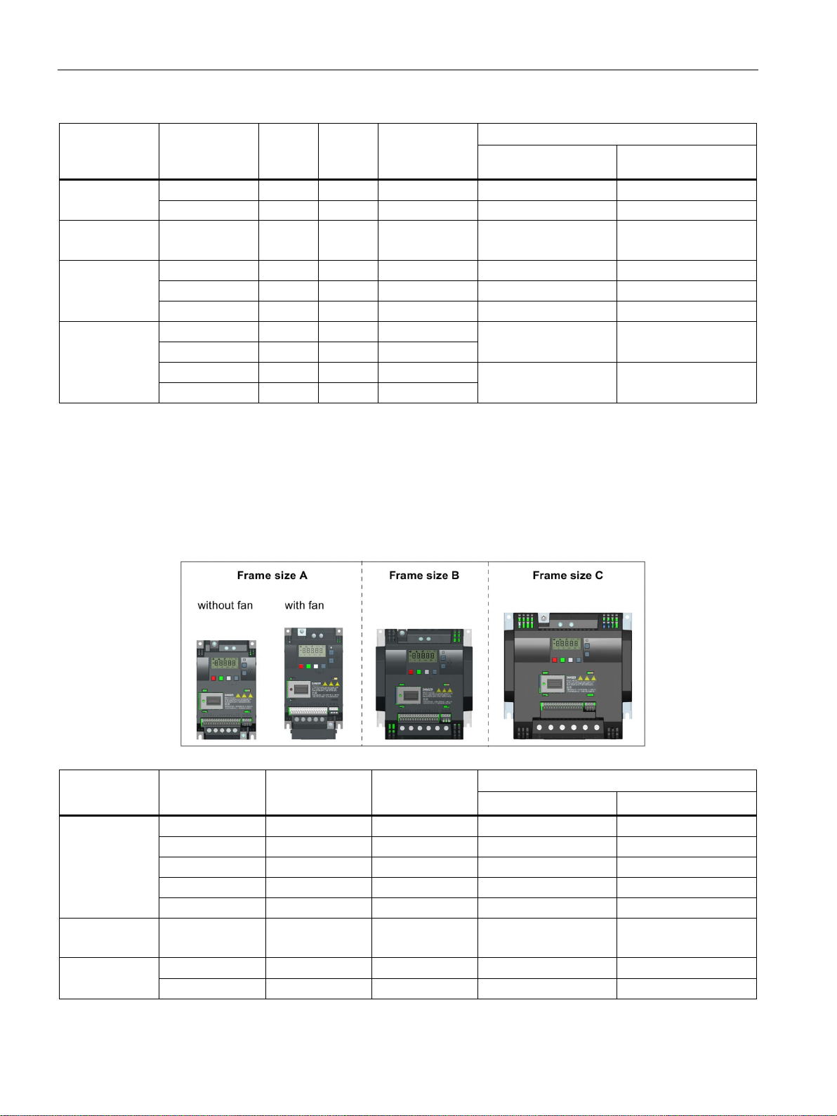
The single phase AC 230 V inverters are available in three frame sizes.
Frame size A
(without fan)
Frame size A
(with single fan)
Frame size B
(with single fan)
SINAMICS V20 Inverter
22 Operating Instructions, 09/2014, A5E34559884
0.12 kW 2.3 A 0.9 A 6SL3210-5BB11-2UV0 6SL3210-5BB11-2AV0
0.25 kW 4.5 A 1.7 A 6SL3210-5BB12-5UV0 6SL3210-5BB12-5AV0
0.37 kW 6.2 A 2.3 A 6SL3210-5BB13-7UV0 6SL3210-5BB13-7AV0
0.55 kW 7.7 A 3.2 A 6SL3210-5BB15-5UV0 6SL3210-5BB15-5AV0
0.75 kW 10 A 3.9 A 6SL3210-5BB17-5UV0 6SL3210-5BB17-5AV0
0.75 kW 10 A 4.2 A 6SL3210-5BB18-0UV0 6SL3210-5BB18-0AV0
1.1 kW 14.7 A 6.0 A 6SL3210-5BB21-1UV0 6SL3210-5BB21-1AV0
1.5 kW 19.7 A 7.8 A 6SL3210-5BB21-5UV0 6SL3210-5BB21-5AV0
Introduction
Component
Rated output
power
Rated input
current
Rated output
current
Order number
unfiltered
filtered
Options and spare parts
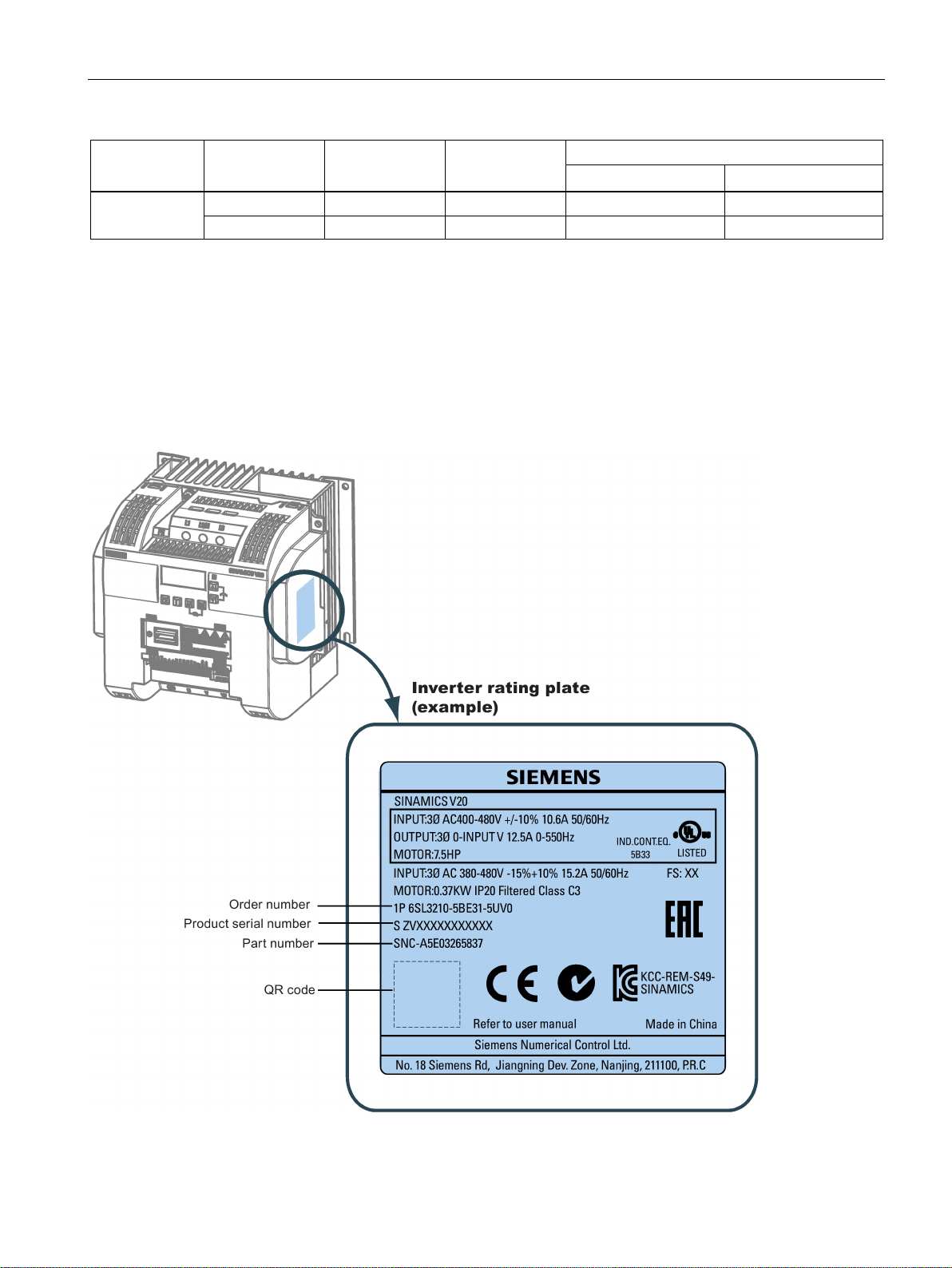
2.2
Inverter rating plate
2.2 Inverter rating plate
Frame size C
(with single fan)
2.2 kW 27.2 A 11 A 6SL3210-5BB22-2UV0 6SL3210-5BB22-2AV0
3.0 kW 32 A 13.6 A 6SL3210-5BB23-0UV0 6SL3210-5BB23-0AV0
For detailed information of the options and spare parts, refer to Appendices "Options
(Page 301)" and "Spare parts - replacement fans (Page 337)".
SINAMICS V20 Inverter
Operating Instructions, 09/2014, A5E34559884
23

Introduction
2.2 Inverter rating plate
SINAMICS V20 Inverter
24 Operating Instructions, 09/2014, A5E34559884
3
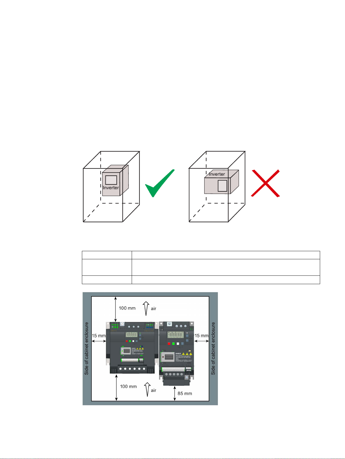
3.1
Mounting orientation and clearance
Mounting orientation
Mounting clearance
The inverter must be mounted in an enclosed electrical operating area or a control cabinet.
Always mount the inverter in an upright position.
Top ≥ 100 mm
Bottom ≥100 mm (for frame sizes B to E, and frame size A without fan)
Side ≥ 0 mm
≥ 85 mm (for fan-cooled frame size A)
SINAMICS V20 Inverter
Operating Instructions, 09/2014, A5E34559884
25
Mechanical installation
3.2
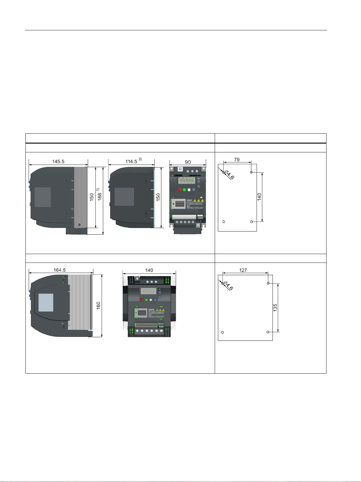
Cabinet panel mounting (frame sizes A to E)
Outline dimensions and drill patterns
Dimensions (mm)
Drill pattern (mm)
3.2 Cabinet panel mounting (frame sizes A to E)
You can mount the inverter directly on the surface of the cabinet panel.
An additional mounting method is also available for different frame sizes. For more details,
refer to the following section:
● Push-through mounting (frame sizes B to E) (Page 30)
Frame size A
1)
Height of frame size A with fan
2)
Depth of Flat Plate inverter (400 V 0.75 kW variant only)
Frame size B
Fixings: 4 x M4 screws, nuts, washers
Tightening torque: 1.8 Nm ± 10%
Fixings: 4 x M4 screws, nuts, washers
Tightening torque: 1.8 Nm ± 10%
SINAMICS V20 Inverter
26 Operating Instructions, 09/2014, A5E34559884
Mechanical installation
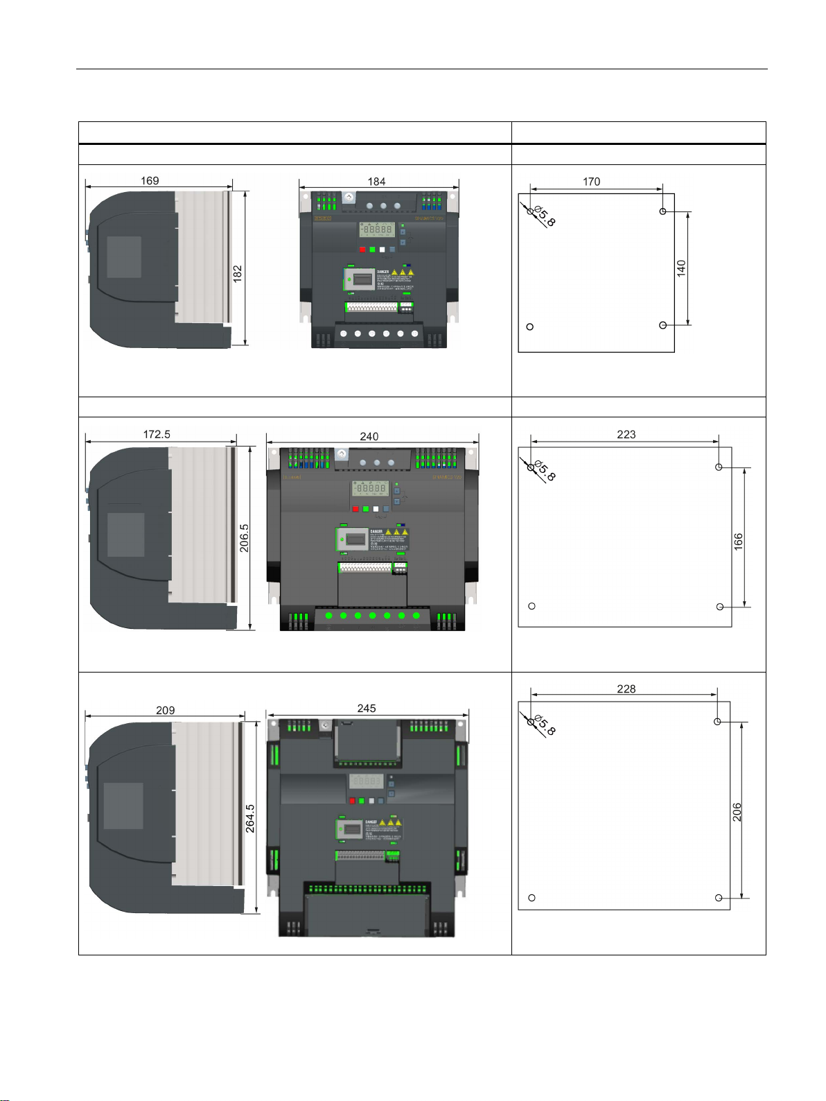
Dimensions (mm)
Drill pattern (mm)
3.2 Cabinet panel mounting (frame sizes A to E)
Frame size C
Frame size D
Frame size E
Fixings: 4 x M5 screws, nuts, washers
Tightening torque: 2.5 Nm ± 10%
Fixings: 4 x M5 screws, nuts, washers
Tightening torque: 2.5 Nm ± 10%
SINAMICS V20 Inverter
Operating Instructions, 09/2014, A5E34559884
Fixings: 4 x M5 screws, nuts, washers
Tightening torque: 2.5 Nm ± 10%
27
Mechanical installation
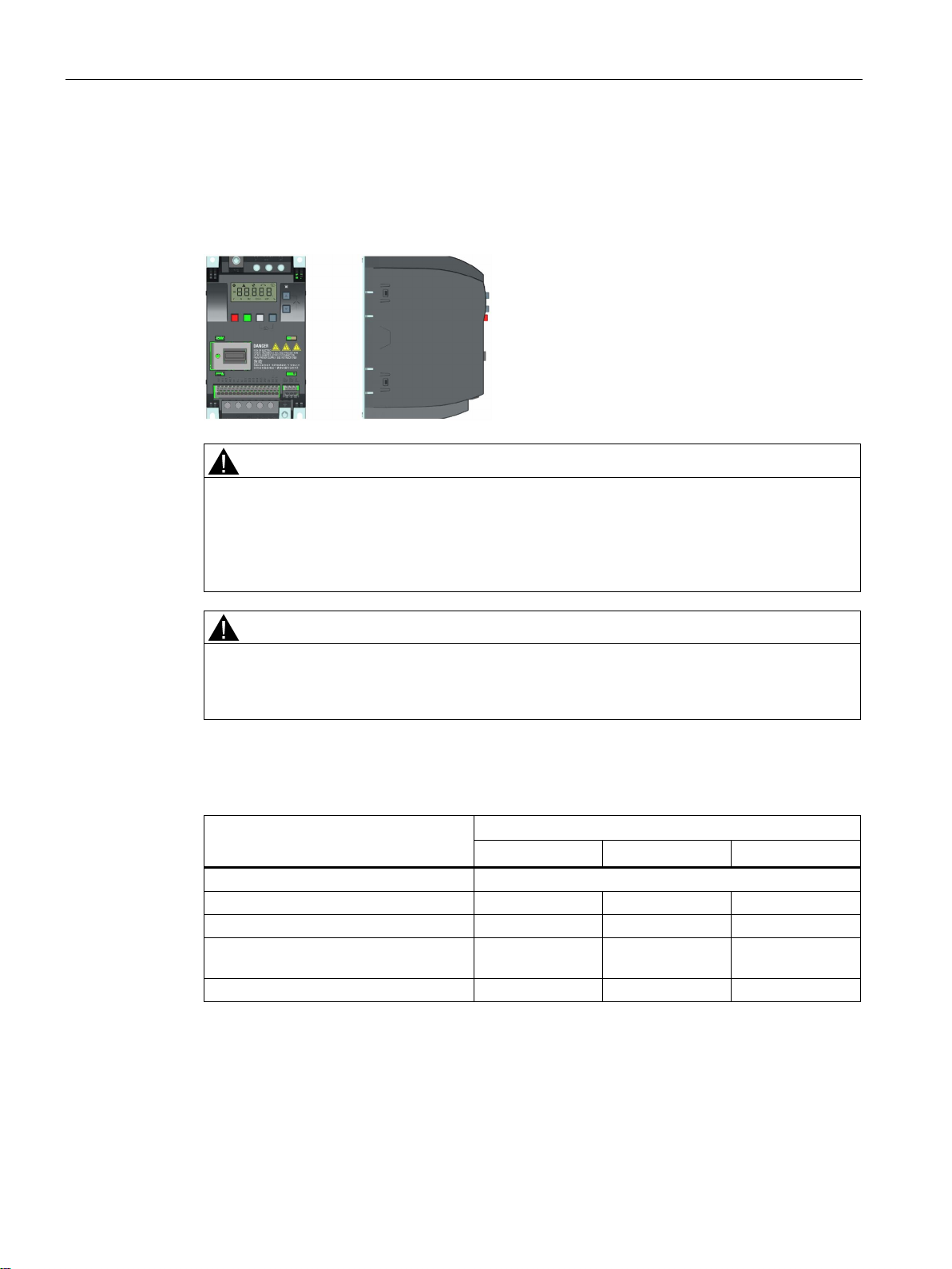
3.3
SINAMICS V20 Flat Plate variant
WARNING
Additional heat load
CAUTION
Cooling considerations
Technical data
Flat Plate variant
6SL3216-5BE17-5CV0
Average power output
* With I/O fully loaded
3.3 SINAMICS V20 Flat Plate variant
The SINAMICS V20 Flat Plate variant is designed to allow greater flexibility in the installation
of the inverter. Adequate measures must be taken to ensure the correct heat dissipation,
which may require an additional external heatsink outside the electrical enclosure.
Operation with an input voltage greater than 400 V and 50 Hz or with a pulse frequency
greater than 4 kHz will cause an additional heat load on the inverter. These factors must be
taken into account when designing the installation conditions and must be verified by a
practical load test.
The minimum vertical clearance of 100 mm above and below the inverter must be
observed. Stacked mounting is not allowed for the SINAMICS V20 inverters.
370 W
Operating temperature range -10 °C to 40 °C
Max. heatsink loss 24 W 27 W 31 W
Max. control loss * 9.25 W 9.25 W 9.25 W
Recommended thermal resistance of
heatsink
Recommended output current 1.3 A 1.7 A 2.2 A
1.8 K/W 1.5 K/W 1.2 K/W
550 W
750 W
SINAMICS V20 Inverter
28 Operating Instructions, 09/2014, A5E34559884

Mechanical installation
Installing
Example:
Note
3.3 SINAMICS V20 Flat Plate variant
1. Prepare the mounting surface for the inverter using the dimensions given in Section
"Cabinet panel mounting (frame sizes A to E) (Page 26)".
2. Ensure that any rough edges are removed from the drilled holes, the flat plate heatsink is
clean and free from dust and grease, and the mounting surface and if applicable the
external heatsink are smooth and made of unpainted metal (steel or aluminium).
3. Apply a non-silicone heat transfer compound with a minimum thermal transfer co-efficient
of 0.9 W/m.K evenly to the rear surface of the flat plate heatsink and the surface of the
rear plate.
4. Mount the inverter securely using four M4 screws with a tightening torque of 1.8 Nm
(tolerance: ± 10%).
5. If it is required to use an external heatsink, first apply the paste specified in Step 3 evenly
to the surface of the external heatsink and the surface of the rear plate, and then connect
the external heatsink on the other side of the rear plate.
6. When the installation is completed, run the inverter in the intended application while
monitoring r0037[0] (measured heatsink temperature) to verify the cooling effectiveness.
The heatsink temperature must not exceed 90 °C during normal operation, after the
allowance has been made for the expected surrounding temperature range for the
application.
If the measurements are made in 20 °C surrounding, and the machine is specified up to
40 °C, then the heatsink temperature reading must be increased by [40-20] = 20 °C, and
the result must remain below 90 °C.
If the heatsink temperature exceeds the above limit, then further cooling must be
provided (for example, with an extra heatsink) until the conditions are met.
The inverter will trip with fault condition F4 if the heatsink temperature rises above 100
°C. This protects the inverter from potential damage due to high temperatures.
SINAMICS V20 Inverter
Operating Instructions, 09/2014, A5E34559884
29
Mechanical installation
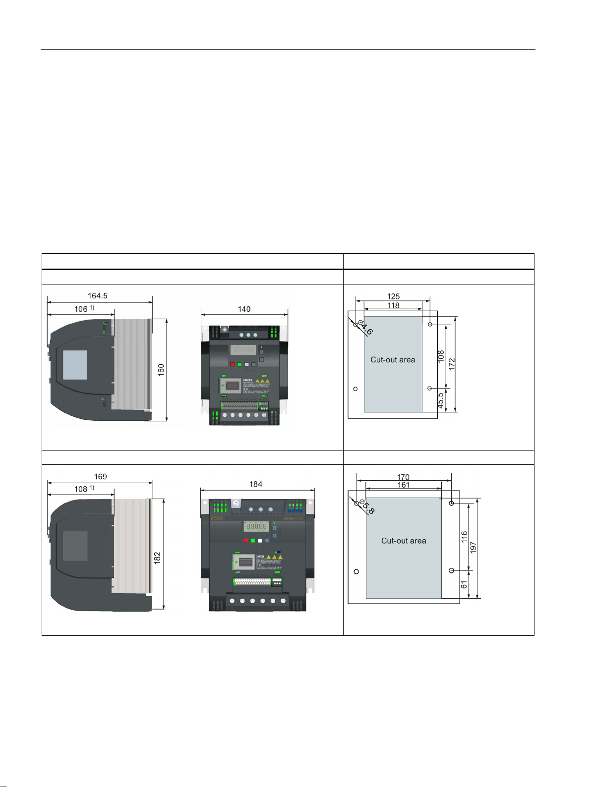
3.4
Push-through mounting (frame sizes B to E)
Outline dimensions, drill patterns, and cut-outs
Dimensions (mm)
Drill pattern and cut-out (mm)
3.4 Push-through mounting (frame sizes B to E)
The frame sizes B to E are designed to be compatible with "push-through" applications,
allowing you to mount the heatsink of the inverter through the back of the cabinet panel.
When the inverter is mounted as the push-through variant, no higher IP rating is achieved.
Make sure that the required IP rating for the enclosure is maintained.
An additional mounting method is also available for different frame sizes. For more details,
refer to the following section:
● Cabinet panel mounting (frame sizes A to E) (Page 26)
Frame size B
Frame size C
Fixings: 4 x M4 screws
Tightening torque: 1.8 Nm ± 10%
Fixings: 4 x M5 screws
Tightening torque: 2.5 Nm ± 10%
SINAMICS V20 Inverter
30 Operating Instructions, 09/2014, A5E34559884
 Loading...