

Siemens SINAMICS V10 Operating Instructions Manual

SINAMICS
SINAMICS V10
Operating Instructions
SW version: V 01.63
08/2011
A5E03453178 (this is not an order number)
Introduction
1
Safety notes
2
Description
3
Identification
4
Installation
5
Commissioning
6
Parameter list
7
Troubleshooting
8
Technical data
9
Replacing the fans
A
Legal information
Warning notice system
This manual contains notices you have to observe in order to ensure your personal safety, as well as to prevent
damage to property. The notices referring to your personal safety are highlighted in the manual by a safety alert
symbol, notices referring only to property damage have no safety alert symbol. These notices shown below are
graded according to the degree of danger.
DANGER
indicates that death or severe personal injury will result if proper precautions are not taken.
WARNING
indicates that death or severe personal injury may result if proper precautions are not taken.
CAUTION
with a safety alert symbol, indicates that minor personal injury can result if proper precautions are not taken.
CAUTION
without a safety alert symbol, indicates that property damage can result if proper precautions are not taken.
NOTICE
indicates that an unintended result or situation can occur if the relevant information is not taken into account.
If more than one degree of danger is present, the warning notice representing the highest degree of danger will be
used. A notice warning of injury to persons with a safety alert symbol may also include a warning relating to property
damage.
Qualified Personnel
The product/system described in this documentation may be operated only by personnel qualified for the specific
task in accordance with the relevant documentation, in particular its warning notices and safety instructions. Qualified
personnel are those who, based on their training and experience, are capable of identifying risks and avoiding
potential hazards when working with these products/systems.
Proper use of Siemens products
Note the following:
WARNING
Siemens products may only be used for the applications described in the catalog and in the relevant technical
documentation. If products and components from other manufacturers are used, these must be recommended or
approved by Siemens. Proper transport, storage, installation, assembly, commissioning, operation and
maintenance are required to ensure that the products operate safely and without any problems. The permissible
ambient conditions must be complied with. The information in the relevant documentation must be observed.
Trademarks
All names identified by ® are registered trademarks of Siemens AG. The remaining trademarks in this publication
may be trademarks whose use by third parties for their own purposes could violate the rights of the owner.
Disclaimer of Liability
We have reviewed the contents of this publication to ensure consistency with the hardware and software described.
Since variance cannot be precluded entirely, we cannot guarantee full consistency. However, the information in
this publication is reviewed regularly and any necessary corrections are included in subsequent editions.
Siemens AG
Industry Sector
Postfach 48 48
90026 NÜRNBERG
GERMANY
A5E03453178 (this is not an order number)
Ⓟ 08/2011
Copyright © Siemens AG 2010.
Technical data subject to change

Table of contents
1 Introduction...................................................................................................................................................5
2 Safety notes..................................................................................................................................................7
3 Description..................................................................................................................................................13
4 Identification...............................................................................................................................................15
5 Installation..................................................................................................................................................21
5.1 Mechanical installation................................................................................................................21
5.1.1 Mounting orientation and clearance............................................................................................21
5.1.2 Wall mounting..............................................................................................................................23
5.1.3 Push-through mounting...............................................................................................................25
5.1.4 Mounting the operator panel to cabinet door...............................................................................31
5.2 Electrical installation....................................................................................................................33
5.2.1 Interface definition.......................................................................................................................33
5.2.2 Connecting power supply to the motor........................................................................................37
6 Commissioning ..........................................................................................................................................39
6.1 Typical connection modes...........................................................................................................39
6.2 Application macros......................................................................................................................56
6.3 Operator panel overview.............................................................................................................58
6.3.1 Function overview of operator panel...........................................................................................59
6.3.2 Various data displays..................................................................................................................60
6.3.3 Displays during inverter initialization stage..................................................................................62
6.4 Quick commissioning...................................................................................................................63
6.5 Inverter status display..................................................................................................................65
6.6 Overview of various operation modes.........................................................................................66
6.6.1 Operation mode ① - Quick motor data setting............................................................................66
6.6.2 Operation mode ② - Connection macro selection.......................................................................67
6.6.3 Operation mode ③ - Application macro selection.......................................................................69
6.6.4 Operation mode ④ - Common application macro specific parameter setting.............................70
6.6.5 Operation mode ⑤ - Access all the parameters..........................................................................71
6.7 Factory reset................................................................................................................................72
6.8 Cloning parameters with the operator panel................................................................................73
7 Parameter list.............................................................................................................................................75
8 Troubleshooting........................................................................................................................................107
9 Technical data..........................................................................................................................................115
A Replacing the fans....................................................................................................................................119
Index.........................................................................................................................................................123
SINAMICS V10
Operating Instructions, 08/2011, A5E03453178 (this is not an order number) 3


Introduction
1
Purpose of this manual
This manual provides customers with information about the proper installation, connecting,
commissioning, operation and maintenance of the SINAMICS V10 inverter.
Internet addresses for SINAMICS V10
You can obtain continually updated information about the product at
SIEMENS Website for the SINAMICS V10 Inverters (http://www.ad.siemens.com.cn/products/
sd)
You can download the SINAMICS V10 user documentation at
SIEMENS Website for the SINAMICS V10 User Documentation (http://
www.ad.siemens.com.cn/download)
Technical support
In case of any questions concerning the product, contact your local distributor.
SINAMICS V10
Operating Instructions, 08/2011, A5E03453178 (this is not an order number) 5


Safety notes
2
This chapter lists safety instructions which apply when handling the SINAMICS V10 inverter.
These instructions are classified as General, Identification, Transport & Storage, Installing,
Connecting, Commissioning, Troubleshooting and Disposal. Please read the information
carefully, since it is provided for your personal safety and will also help prolong the service life
of your inverter and the equipment connected to it.
General
WARNING
This equipment contains dangerous voltage and controls potentially dangerous rotating
mechanical parts. Failure to work on the equipment/system in accordance with the
instructions/procedures contained in this manual can result in death, severe personal injury
or considerable damage to property.
Only appropriately qualified personnel should work on the inverter system, and only after
becoming acquainted with all the safety instructions, installation, connecting, operation and
maintenance procedures contained in this manual.
Any unauthorized modification of the equipment is NOT allowed.
To fulfill the requirements of CE and Low Voltage directives, the equipment must be mounted
in a metal cabinet and accessories like chokes should be used.
The equipment will automatically restart after a mains blackout, brownout or fault if automatic
restart (configured with parameter P1210) is activated, thus please check whether there is
any necessity to set parameter P1200 (flying restart) again.
When setting a connection mode code or resetting (via P0970) the inverter to factory default
parameter values, it is NOT allowed to operate the inverter via external signal source.
If the equipment has been stored for over 1 year before installation, you must recharge
capacitors in the inverter first. For specific recharging requirements, consult your local
distributor or local dealer.
SINAMICS V10
Operating Instructions, 08/2011, A5E03453178 (this is not an order number) 7
CAUTION
Children and the general public must be prevented from accessing or approaching the
equipment!
This equipment may only be used for the purpose specified by the manufacturer. Any
unauthorized modification and the use of accessories that are not sold or recommended by
the manufacturer of the equipment can cause fire, electric shock or injury.
The operator panel of the SINAMICS V10 inverter does NOT support plug and play. When
you are in an attempt to switch between LOC and REM control modes via an external signal
source, make sure that the communication between the operator panel and the inverter body
unit is in good condition.
NOTICE
Keep this manual as a handy reminder and make them available to all users, if necessary.
Identification
WARNING
Make sure that deliverables received are free from damage and in conformity with your
purchase order. Should any damage or inconsistence with the purchase order be found,
contact your local distributor or local dealer.
It's not permissible to put the equipment into use if it's damaged or short delivered.
Transport & Storage
CAUTION
Transport and storage must meet the specified environmental conditions (see topic Technical
data (Page 115) for details).
Installing
WARNING
Risk of fire or electric shock. Do not install the equipment in an area subject to inflammables
or combustibles, water or corrosion hazards.
Safety notes
SINAMICS V10
8 Operating Instructions, 08/2011, A5E03453178 (this is not an order number)
CAUTION
Do not install the equipment in an area where it is likely to be exposed to constant vibrations,
physical shocks or interference from electromagnetic field.
Risk of fire. Make sure that no foreign body (e.g., chips of wood or metal, dust, paper, etc.)
falls into the inverter or lie on the heatsink of the inverter.
Keep sufficient clearance between inverters, one inverter and another device/the inner wall
of the cabinet. (See topic "Mounting orientation and clearance (Page 21)" for clearance
requirements).
The inverter MUST NOT be mounted horizontally.
Connecting
WARNING
The inverter must have been disconnected from the power supply for at least five minutes
before you perform any wiring to the inverter.
Make sure that all connections are correct and reliable. Only permanently-wired input power
connections are allowed and the inverter must be well grounded (IEC 536 Class 1, NEC and
other applicable standards).
According to IEC 61800-5-1, a PDS (Power Drive System) with leakage currents over 3.5
mA requires a secure ground connection (e.g., at least 10 mm2 Cu or multiple connection) or
an automatic shutdown in case of a ground connection fault.
To avoid input power cable wires loosening or dropping from the mains input terminal
connector, use a proper clamp to secure the input power connections.
If you have to install a Residual Current-operated protective Device (RCD), it must be an
RCD type B.
Use of the protection from direct contact by means of SELV/PELV is permitted only in areas
with equipotential bonding and in dry interior spaces. If these conditions are not present, other
protective measures against electric shock must be taken, e.g., protection through protective
impedances or limited voltage or use of protection class I and II.
Only PELV or SELV voltages may be connected at terminals with either PELV or SELV
voltages (refer to EN 60204-1, Section 6.4).
CAUTION
The rated mains input voltage to the inverter must be 3 AC 400 V.
Never connect the mains input cable to the motor terminals U, V, W or connect the motor
cable to the mains input terminals L1, L2, L3.
Route signal cables and power cables separately in different cable conduits. The signal
cables shall be at least 10 cm away from the power cables.
Keep connecting cables away from rotating mechanical parts.
Safety notes
SINAMICS V10
Operating Instructions, 08/2011, A5E03453178 (this is not an order number) 9
Commissioning
WARNING
Before switching the power on, make sure that the inverter system has been reliably installed
and connected, and the mains voltage is within the allowable range.
Do not touch the motor shaft when the motor is running. Failure to comply may cause personal
injury.
Risk of electric sock. DC link capacitors remain charged for five minutes after power-off. It is
not allowed to open the equipment until five minutes has elapsed since power-off.
The following inverter terminals can carry dangerous voltages even if the inverter is
inoperative:
- Mains input terminals L1, L2, L3
- Motor terminals U, V, W.
This equipment must not be used as an "emergency stop mechanism" (
see EN 60204,
9.2.5.4
).
It's not allowed to open the equipment or connect/disconnect the equipment during its
operation.
When inverter is confirming a selected connection macro, cloning parameters or reset via
P0970, it's NOT allowed to attempt to control the inverter operation via an external digital
input.
CAUTION
Motor commissioning under loaded conditions may only be performed after motor
commissioning under no-load (dry-run) conditions.
Do not touch the inverter heatsink, motor or other high-temperature parts during equipment
operation or within a certain period since power disconnection. Failure to comply may cause
personal injury.
Do not run or stop the inverter by switching on/off the mains supply frequently. This may
cause damage to the equipment/system.
Troubleshooting
WARNING
Even if damage is only suspected (for example, water), don't operate the equipment but
contact your distributor.
Do not touch terminals or disassemble cables until the inverter system has been disconnected
for at least five minutes, because the inverter may remain charged during this period.
Troubleshooting may only be performed by personnel furnished with necessary expertise, or
there is a risk of electric shock or damage to the equipment.
Safety notes
SINAMICS V10
10 Operating Instructions, 08/2011, A5E03453178 (this is not an order number)
CAUTION
Do not approach the machine after an input power failure! Certain parameter settings of the
inverter can cause the machine to restart automatically.
Disposal
WARNING
Disposal of the equipment must be made in accordance with regulations of the competent
environmental protection administration on the disposal of electronic wastes.
Safety notes
SINAMICS V10
Operating Instructions, 08/2011, A5E03453178 (this is not an order number) 11


Description
3
Overview
The SINAMICS V10 inverters are designed for controlling the speed of three phrase AC
asynchronous squirrel cage motors. The available inverter versions range from the 0.55 kW
three phase output power to the 22 kW three phase output power.
The inverters are microprocessor-controlled and use state-of-the-art IGBT technology. A
special pulse-width modulation method with selectable pulse frequency permits quiet motor
operation. Comprehensive protective functions provide excellent inverter and motor protection.
SINAMICS V10 with its default factory settings is ideal for a large range of simple motor control
applications. By configuring relevant parameters, you can use the inverter for some advanced
motor control operations. In addition, the SINAMICS V10 inverters are also suitable for use in
"stand-alone" applications or being integrated into "Automation Systems" via input/output
signals.
SINAMICS V10
Operating Instructions, 08/2011, A5E03453178 (this is not an order number) 13

Features
● Main characteristics
– Easy installation and commissioning, simple cable connection
– Can be operated on TNC, TNS, TT or IT mains systems
– A comprehensive range of parameters enabling configuration for a wide range of simple
applications
– Compact design for fast installation
– High switching frequencies for low-noise motor operation
● Performance characteristics
– Fast Current Limitation (FCL) for normal operation under sudden load changes
– Built-in DC braking mode
– Compound braking to improve braking performance
– V/f control with linear characteristic
– V/f control with Flux Current Control (FCC)
– V/f control with parabolic characteristic
– Acceleration/deceleration times with programmable smoothing
– Integrated PI controller for simple process control
● Protection characteristics
– Short-circuit protection
– Over-current protection
– Inverter and motor over-temperature protection
– Over-voltage and under-voltage protection
– Load-side ground fault protection
– Motor blocking protection
– Parameter interlock
Description
SINAMICS V10
14 Operating Instructions, 08/2011, A5E03453178 (this is not an order number)
Identification
4
Scope of delivery
When opening the delivered SINAMICS V10 inverter package, check that the following
components are included:
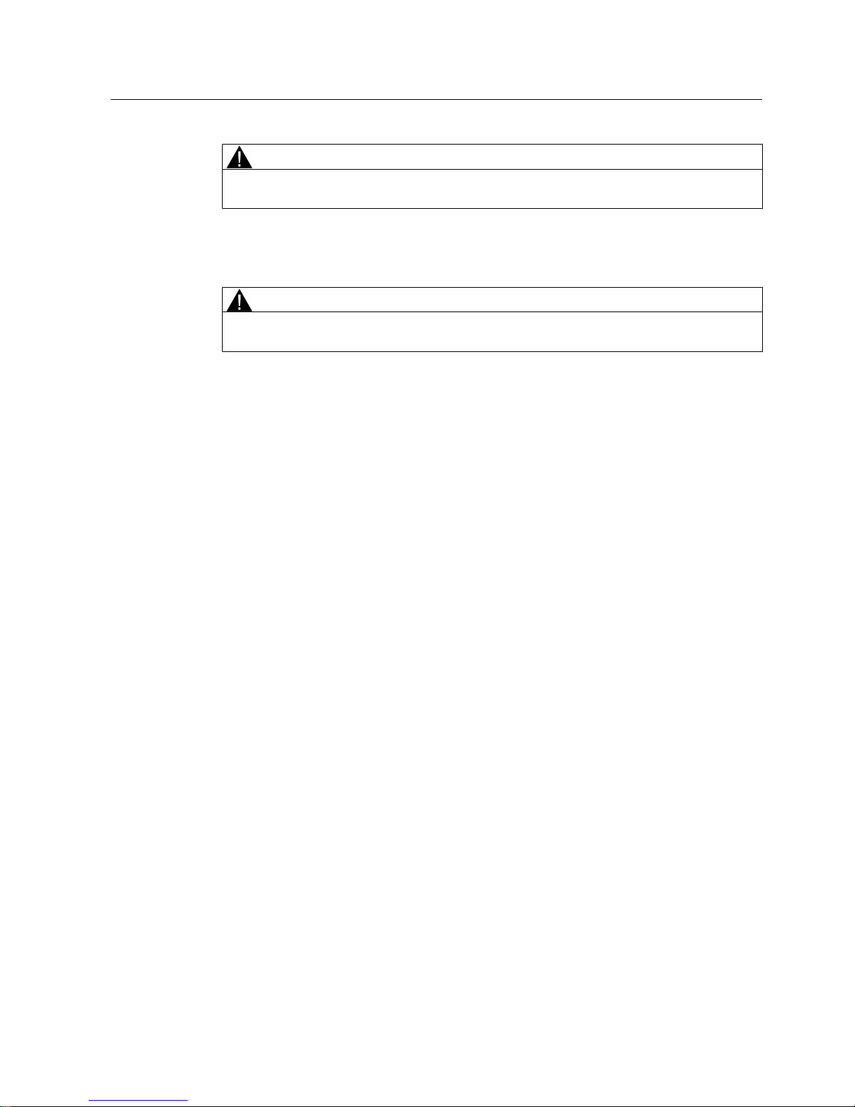
Table 4-1 Scope of delivery (SINAMICS V10 Inverter + Quick Start Guide + Certificate)
Component Variant Rated output power MLFB (order number)
SINAMICS V10 Inverter
Frame Size A 0.55 kW 6SL3217-0CE15-5UA1
0.75 kW 6SL3217-0CE17-5UA1
1.1 kW 6SL3217-0CE21-1UA1
1.5 kW 6SL3217-0CE21-5UA1
Frame Size B 2.2 kW 6SL3217-0CE22-2UA1
3.0 kW 6SL3217-0CE23-0UA1
4.0 kW 6SL3217-0CE24-0UA1
Frame Size C 5.5 kW 6SL3217-0CE25-5UA1
7.5 kW 6SL3217-0CE27-5UA1
11 kW 6SL3217-0CE31-1UA1
Frame Size D 15 kW 6SL3217-0CE31-5UA1
18.5 kW 6SL3217-0CE31-8UA1
22 kW 6SL3217-0CE32-2UA1
)UDPH6L]H$)UDPH6L]H&)UDPH6L]H')UDPH6L]H%
Quick Start Guide
1)
English version - -
1)
The documentation identification number of the Quick Start Guide is A5E02583918 (this is not an order number).
SINAMICS V10
Operating Instructions, 08/2011, A5E03453178 (this is not an order number) 15
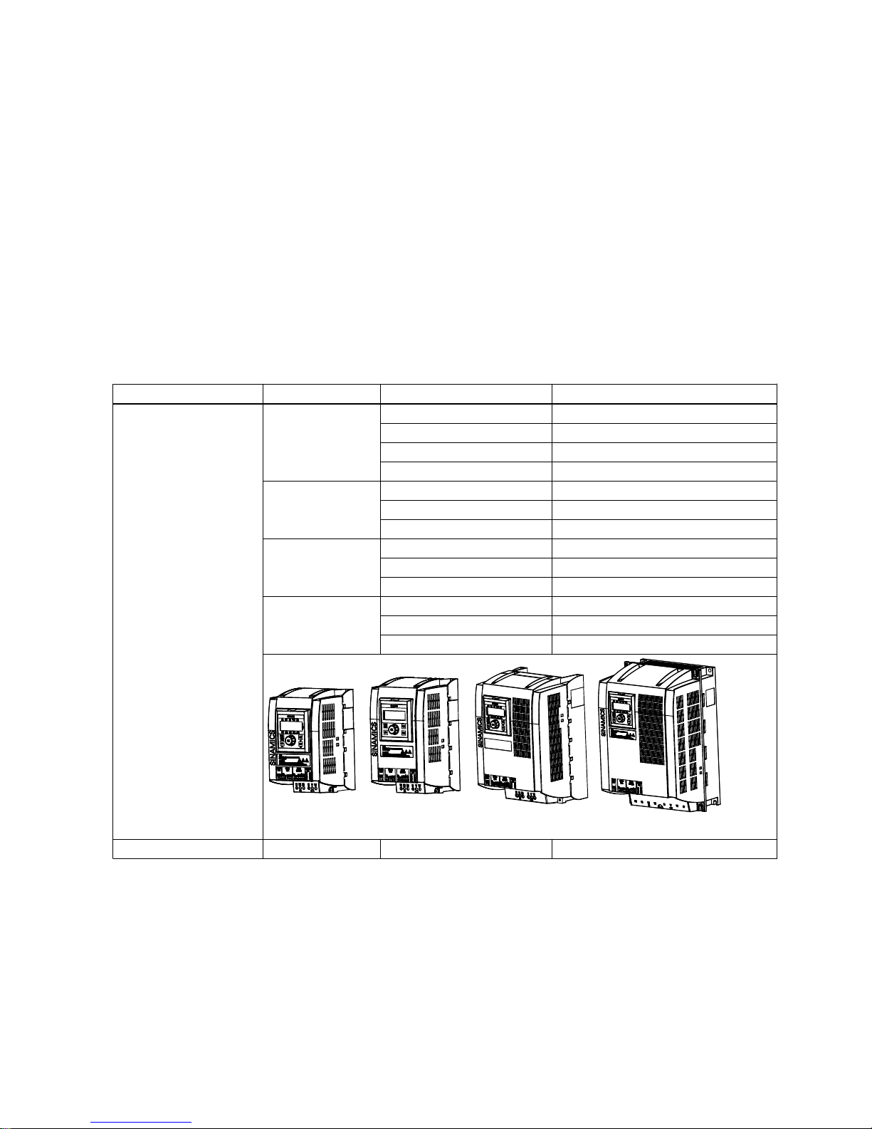
Inverter rating plate
Check the information shown on the inverter rating plate against your purchase order. Viewing
from the inverter front, the rating plating is located on the right side of the inverter housing.
Inverter rating plate
SINAMICS V10 Frame Size A
Product name
Product serial number
Mains input
Hardware version
Firmware version
Mains output
Protection class
Rated motor output power
Siemens part number
MLFB (order number)
6,1$0,&69
9(56,21
):9
$
36/&(8$
6=9:2<97
61&$(
0RWRUN:
,QSXW$&9$+=
2XWSXW$&9$+=
0DGHLQ&KLQD
3URWHFWLRQ,3VHHPDQXDO
Figure 4-1 Inverter rating plate (example)
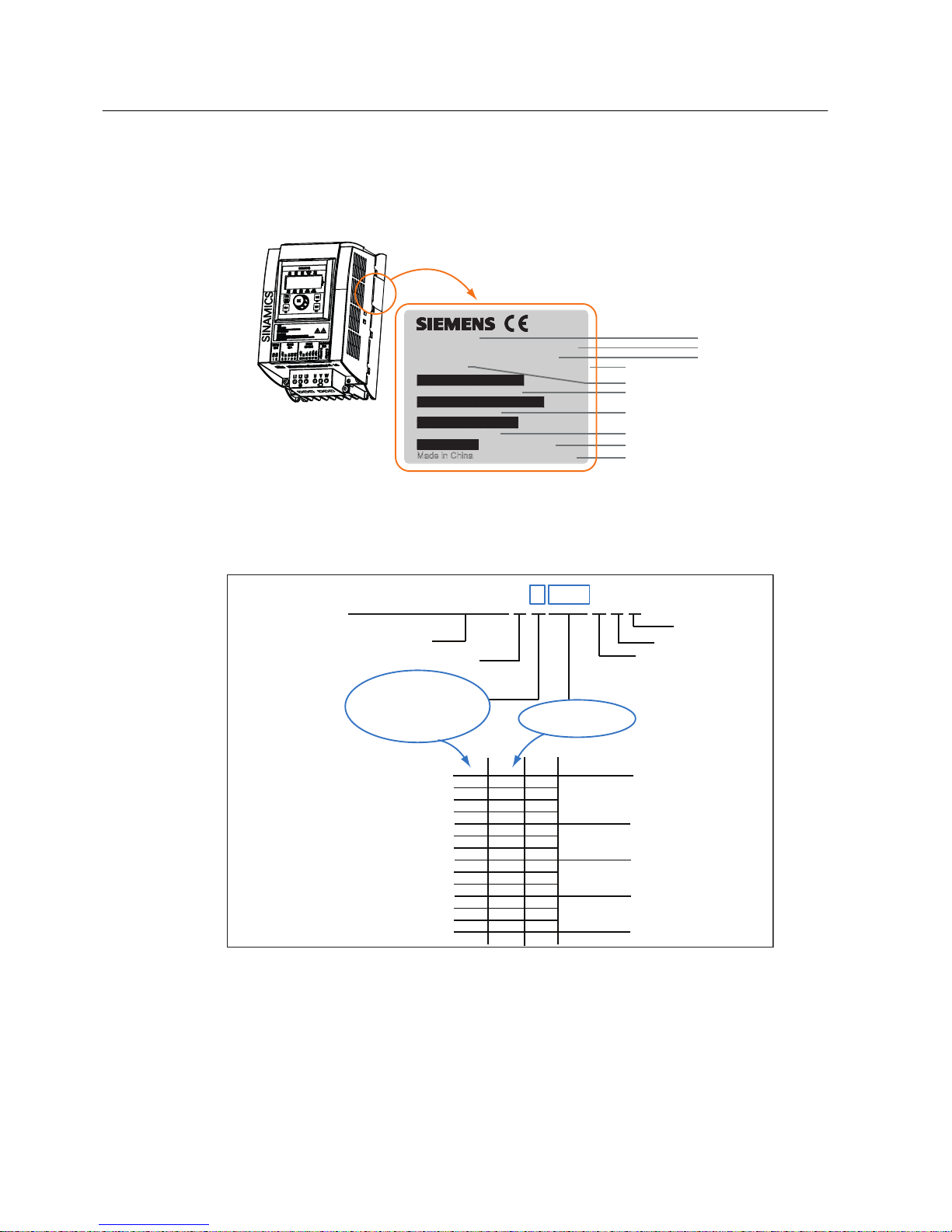
Inverter MLFB (order number) explanation
SINAMICS V10 AC inverter, frame size
Rated mains input voltage: 3 AC 380 V
Unfiltered
Rated output power
Standard
Hardware version
Multiplier for output power:
1: x 0.1
2: x 1
3: x 10
6 S L 3 2 1 7 - 0 C E 2 1 - 5 U A 1
Inverter variant
kW
Frame size A
Frame size B
Frame size C
Frame size D
1
1
2
2
5 - 5
7- 5
2 - 2
3 - 0
4 - 0
1 - 1
1 - 5
1 - 8
2 - 2
5 - 5
7 - 5
1 - 1
1 - 5
2
2
2
3
3
3
3
2
2
0.55
0.75
1.1
1.5
2.2
3.0
4.0
11
15
18
22
5.5
7.5
Figure 4-2 Inverter MLFB (Order Number) explanation
Identification
SINAMICS V10
16 Operating Instructions, 08/2011, A5E03453178 (this is not an order number)
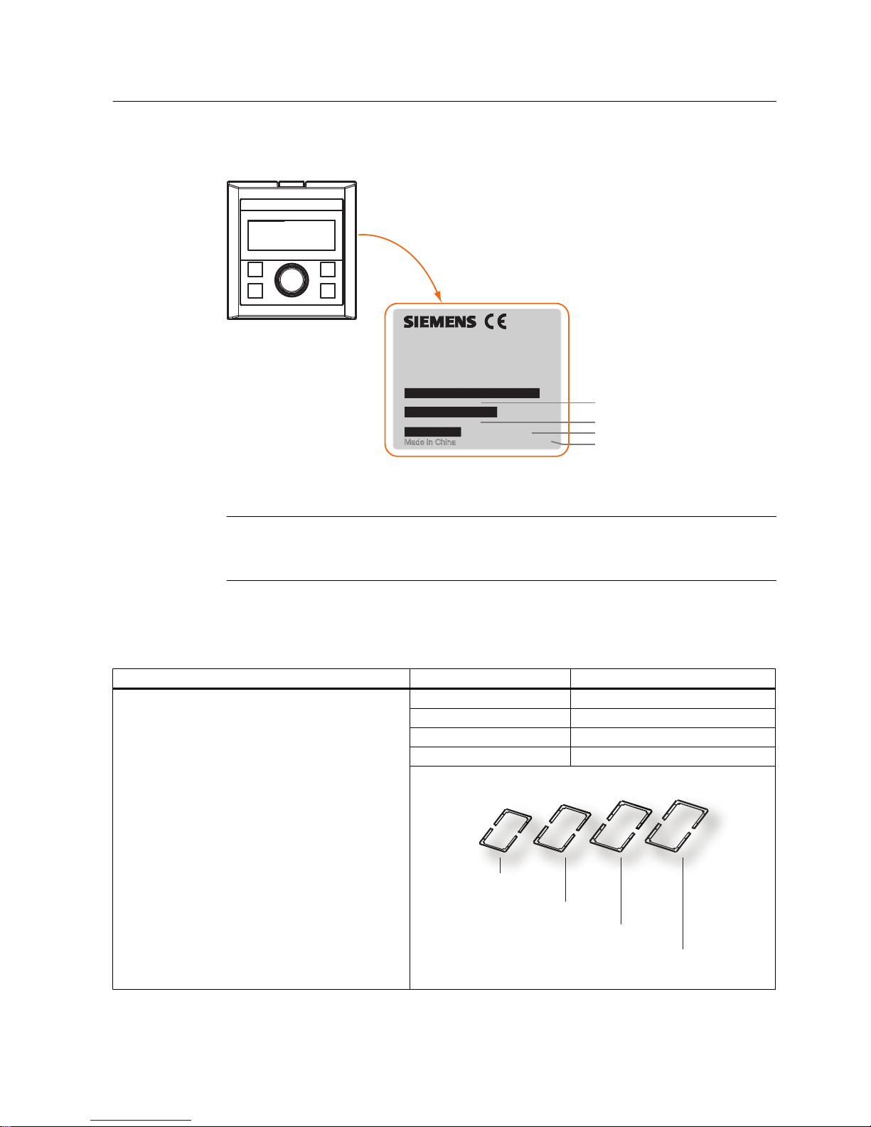
Rating plate on the rear of the operator panel
Rating plate on the rear of the operator panel
Product serial number
Hardware version
Firmware version
Siemens part number
6,1$0,&692SHUDWRU3DQHO
9(56,21$
6=9:2<9&
61&$(
0DGHLQ&KLQD
):9
Figure 4-3 The operator panel rating plate
Note
Beside operator panel rating plate, there is a small label. This label indicates the firmware
version of the operator panel.
Options
Option Variant MLFB (order number)
Push-through mounting components
The push-through mounting components include:
● Push-through mounting kit (1 set)
2)
● Production Information Sheet (1 piece)
● Plastic rivets (2 pieces)
● Metal back cover (1 piece)
3)
● Mounting screws:
– Frame Size A: 4 x M5 screws
– Frame Size B: 4 x M5 screws
– Frame Size C: 8 x M5 screws
– Frame Size D: 8 x M5 screws + 4 x M8 screws
● Mounting nuts
– Frame Size A: 4 x M5 nuts
– Frame Size B: 4 x M5 nuts
– Frame Size C: 8 x M5 nuts
– Frame Size D: 8 x M5 nuts + 4 x M8 nuts
Frame Size A specific 6SL3261-6AA00-0VA0
Frame Size B specific 6SL3261-6AB00-0VA0
Frame Size C specific 6SL3261-6AC00-0VA0
Frame Size D specific 6SL3261-6AD00-0VA0
(6-hole, for Frame Size A)
(6-hole, for Frame Size B)
(10-hole, for Frame Size C)
(14-hole, for Frame Size D)
Push-through mounting kit variants
Identification
SINAMICS V10
Operating Instructions, 08/2011, A5E03453178 (this is not an order number) 17
Option Variant MLFB (order number)
Door mounting components
The door mounting components include:
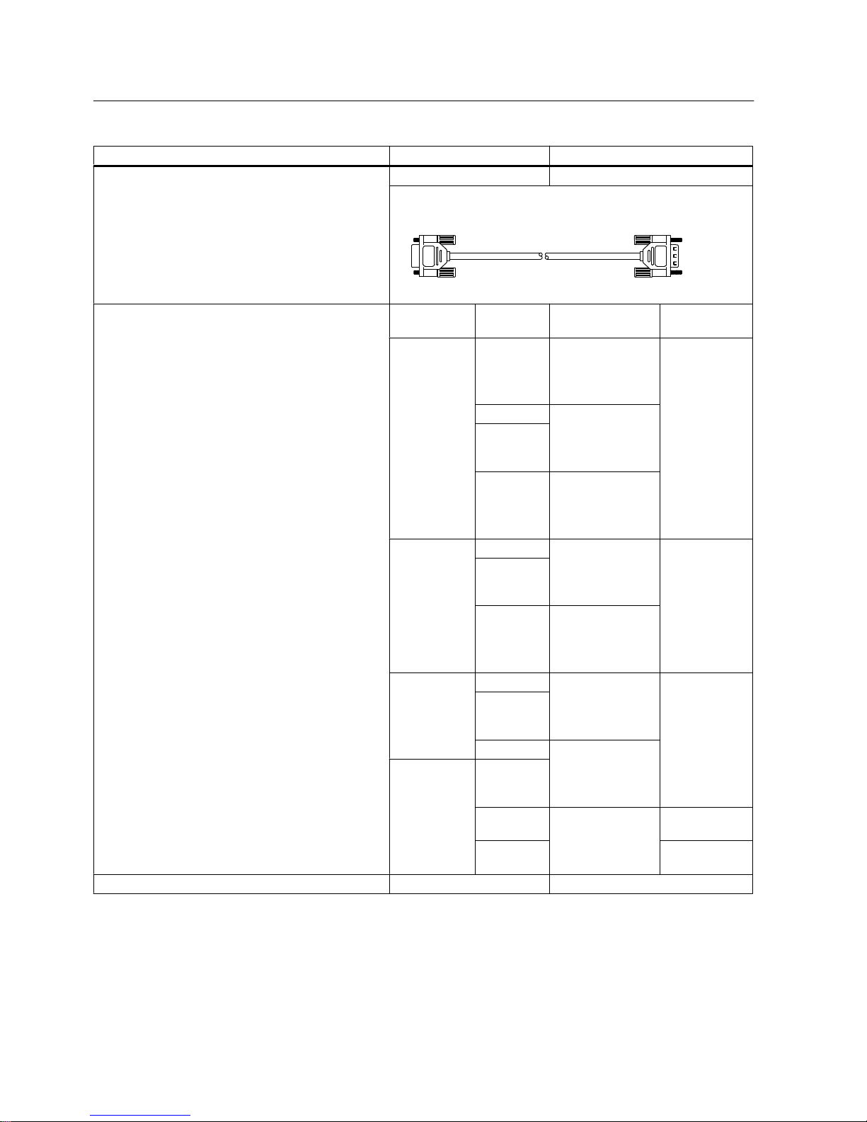
● Connecting cable, 3-meter long (1 piece)
● Production Information Sheet (1 piece)
● M3 preassembled screw and washer assemblies
(4 pieces)
- 6SL3256-0VP00-0VA0
To: inverter body unit
To: door-mounted operator panel
Connecting cable (inverter body unit to operator panel)
Choke
4)
Line commutating choke: A line commutating choke is
required to smooth spike pulses in power voltage, or
voltage sags generated during the phase change of a
bridge rectifier circuit; besides, a line commutating
choke can also used to lower harmonic interference to
inverter and power supply. If power impedance < 1%,
a line commutating choke is a must to reduce current
spikes.
Output choke: An output choke is necessary for
lowering varying rate of capacity current and voltage
(dv/dt) if the length of motor cable is longer than 50m
(shielded) or 100m (unshielded). For the detailed
information about the length of motor cable, please
refer to Technical data (Page 115)
Frame size Rated out
put power
Line commutating
choke
Output choke
Frame Size A 0.55 kW 6SE6400-3CC00-
2AD3
(6SE6400-3CR00-
2AD3)
6SE6400-3TC0
0-4AD2
0.75 kW 6SE6400-3CC004AD3
(6SE6400-3CR004AD3)
1.1 kW
1.5 kW 6SE6400-3CC006AD3
(6SE6400-3CR006AD3)
Frame Size B 2.2 kW 6SE6400-3CC01-
0BD3
(6SE6400-3CR01-
0BD3)
6SE6400-3TC0
1-0BD3
3.0 kW
4.0 kW 6SE6400-3CC014BD3
(6SE6400-3CR014BD3)
Frame Size C 5.5 kW 6SE6400-3CC02-
2CD3
(6SE6400-3CR02-
2CD3)
6SE6400-3TC0
3-2CD3
7.5 kW
11 kW 6SE6400-3CC03-
5CD3
(6SE6400-3CR03-
5CD3)
Framze Size D15 kW
18.5 kW 6SE6400-3CC044DD0
(6SE6400-3CR044DD0)
6SE6400-3TC0
5-4DD0
22 kW 6SE6400-3TC0
3-8DD0
Operating Instructions
5)
English version -
2)
The mounting kit consists of two mating parts. You can well engage both parts when installing.
3)
Only used for Frame Size D
4)
An order number without a bracket indicates that this choke is manufactured by a non-Chinese company, while an order
number with a bracket indicates that this choke is supplied by a local Chinese company. You can make your selection
according to your own needs.
Identification
SINAMICS V10
18 Operating Instructions, 08/2011, A5E03453178 (this is not an order number)

5)
The documentation identification number of the Operating Instructions (English version) is A5E02583916 (this is not an
order number).
Spare parts
Spare parts Variant MLFB (order number)
Fan components
The fan components for Frame Size B include:
● Fan (1 piece)
● Production Information Sheet (1 piece)
● M3 Mounting screws (2 pieces)
The fan components for Frame Size C or Frame Size D
include:
● Fan (1 piece)
● Production Information Sheet (1 piece)
● M4 Mounting screws (2 pieces)
● Spacers (2 pieces)
Frame Size B specific 6SL3200-0VF02-0AA0
Frame Size C specific 6SL3200-0VF03-0AA0
Frame Size D specific 6SL3200-0VF04-0AA0
Operator panel - 6SL3200-0VB01-0AA0
Identification
SINAMICS V10
Operating Instructions, 08/2011, A5E03453178 (this is not an order number) 19

Installation
5
5.1 Mechanical installation
5.1.1 Mounting orientation and clearance
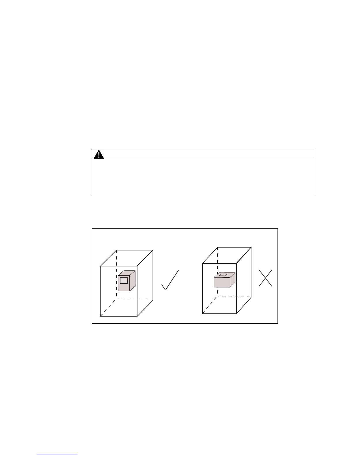
WARNING
Depending on the mounting method selected, you MUST mount the inverter vertically
● in a cabinet or
● in a cabinet, but with the inverter heasink extending outside the cabinet.
Do NOT mount the inverter horizontally in the cabinet.
Mounting orientation
+RUL]RQWDOPRXQWLQJ)RUELGGHQ
9HUWLFDOPRXQWLQJLQFDELQHW0XVW
,QYHUWHU
Figure 5-1 Mounting orientation
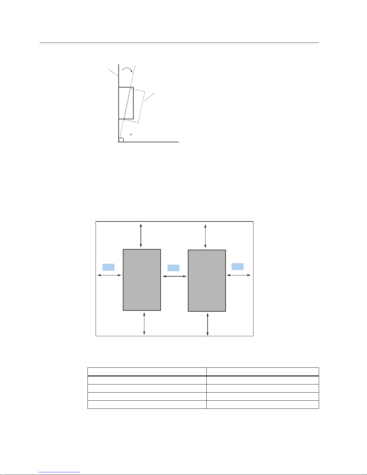
When performing vertical mounting, you can mount the inverter with an angle of 87° to 90°
between inverter and horizontal surface. See figure below for details:
SINAMICS V10
Operating Instructions, 08/2011, A5E03453178 (this is not an order number) 21
,QYHUWHUIURQW
PLQLQXP
+RUL]RQWDO
&DELQHWZDOO
Figure 5-2 Allowed mounting angle between inverter and the horizon
Mounting clearance
You can mount inverters one next to another or one above another with the clearance below:
● Allow at least 100 mm clearance above and below the inverter..
● Allow at least specified clearance A (see Figure 5-3 and Table 5-1 below) between the
inverters.
≥100 mm
≥100 mm
≥100 mm
≥100 mm
A
A
A
SINAMICS V10
SINAMICS V10
SINAMICS V10
SINAMICS V10
Figure 5-3 Inverter mounting clearance
Table 5-1 Requirements for inverter mounting clearance
Inverters positioned side by side Minimum clearance ("A") in mm
Frame Size A ↔ Frame Size A 50
Frame Size B ↔ Frame Size A / B 50
Frame Size C ↔ Frame Size A / B / C 70
Frame Size D ↔ Frame Size A / B / C / D 75
Installation
5.1 Mechanical installation
SINAMICS V10
22 Operating Instructions, 08/2011, A5E03453178 (this is not an order number)
5.1.2 Wall mounting
What does "Wall mounting" mean?
The term "Wall mounting" means:
1. The inverter mounts directly to a cabinet wall, without use of optional mounting kit.
2. The entire inverter including its heatsink mounts inside the cabinet.
3. You don't need an external fan to cool the inverter.
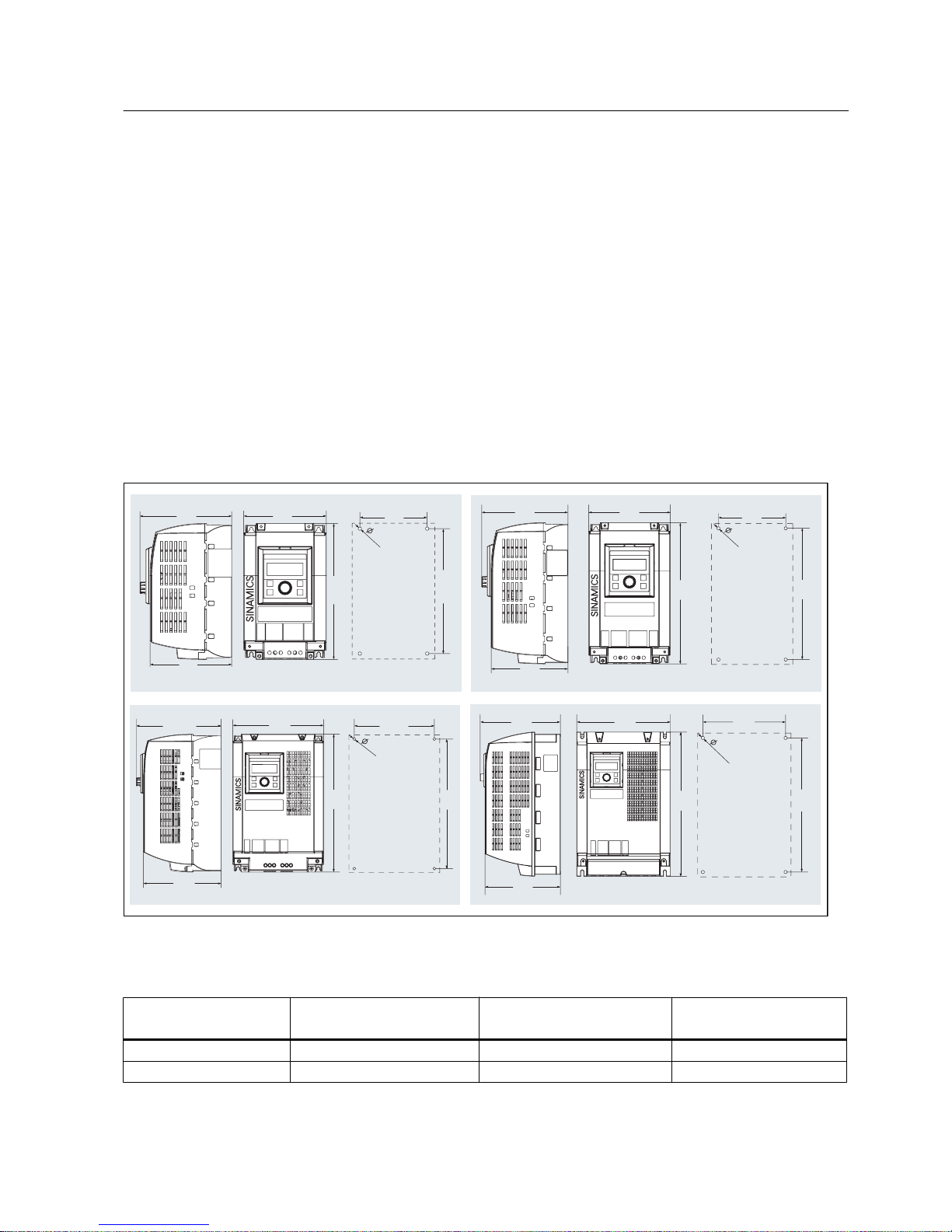
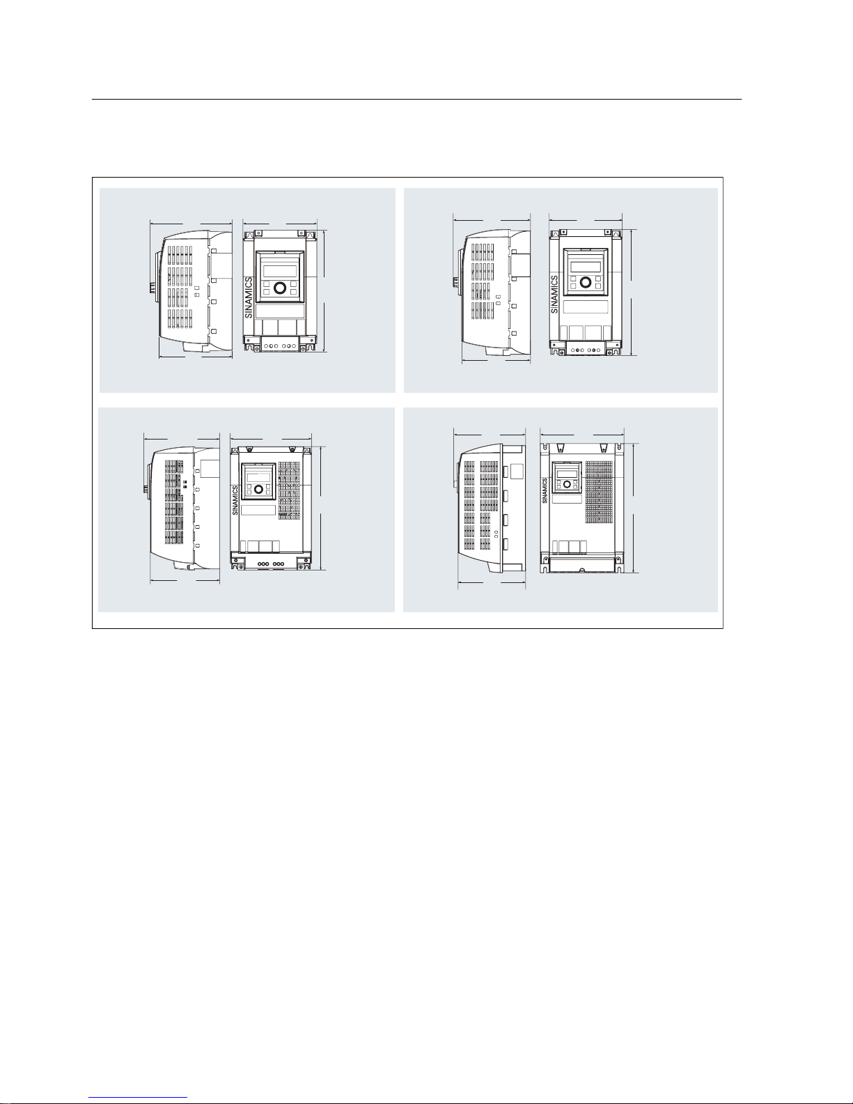
Mounting dimensions (outline dimensions + drill patterns)
You can drill holes in cabinet wall according to the drill patterns shown below. The inverter
outline dimensions are also provided in the figure for your reference:
5.8
155
138
114
211.5
140
230
5.8
142
159
150
124
260
242
7
192.5
218
203.11
186
331
311
230260223
210
401
373
8.
8
)UDPH6L]H$
)UDPH6L]H%
)UDPH6L]H&
)UDPH6L]H'
'ULOOSDWWHUQ
'ULOOSDWWHUQ
'ULOOSDWWHUQ
'ULOOSDWWHUQ
Figure 5-4 Mounting dimensions (in mm)
Table 5-2 Mounting torque requirements
Inverter variant Holes to be drilled in cabinet
wall
Fixing method Tightening torque
(Nm)
Frame Size A 4 4 x M5 screws and nuts 2.5
Frame Size B 4 4 x M5 screws and nuts 2.5
Installation
5.1 Mechanical installation
SINAMICS V10
Operating Instructions, 08/2011, A5E03453178 (this is not an order number) 23
Inverter variant Holes to be drilled in cabinet
wall
Fixing method Tightening torque
(Nm)
Frame Size C 4 4 x M6 screws and nuts 2.5
Frame Size D 4 4 x M8 screws and nuts 2.5
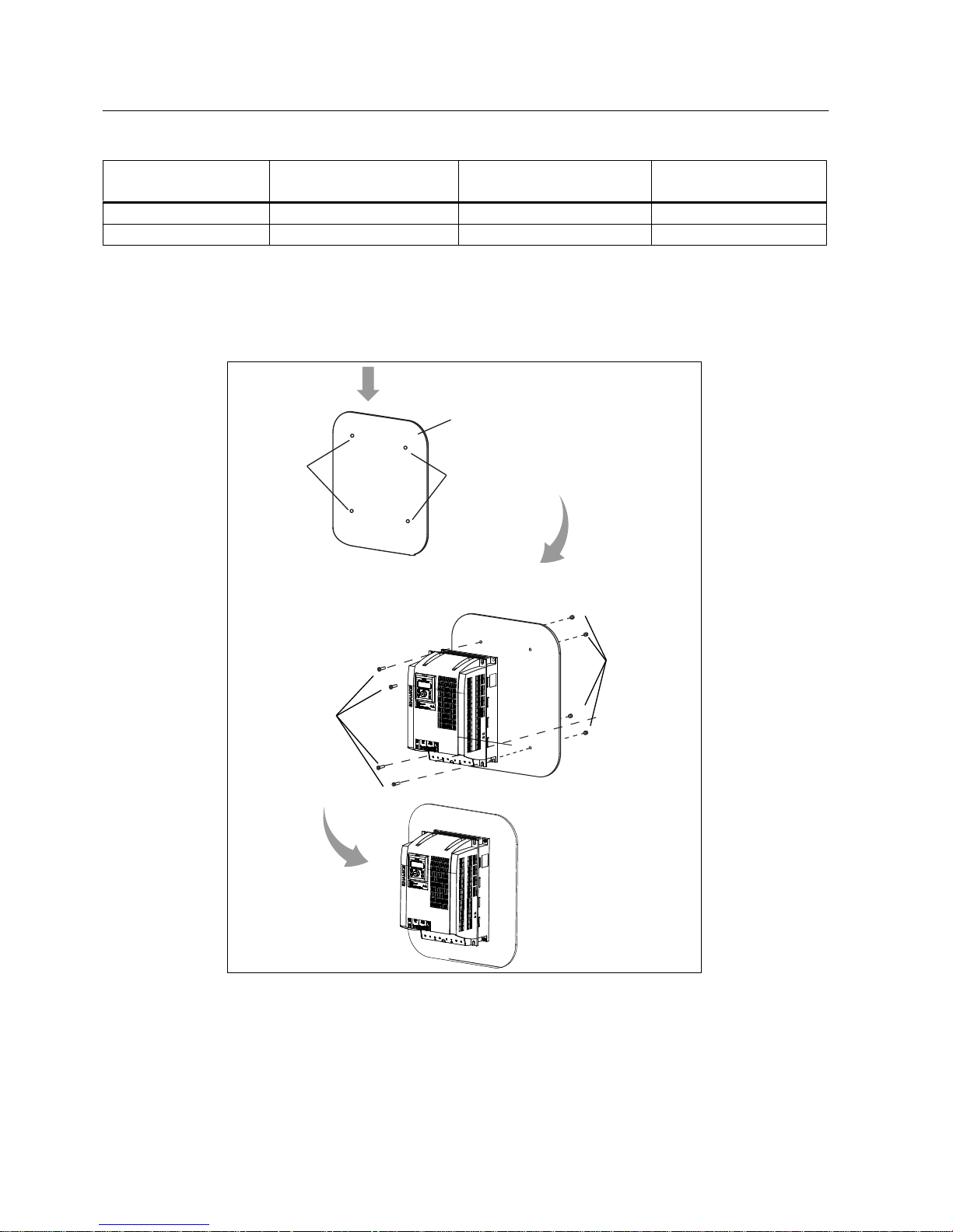
Mounting sequence
Proceed the following procedure to complete your mounting of the inverter directly to cabinet
wall:
Cabinet wall
Mounting holes
1.
Drill 4 holes in cabinet wall
1
Mounting
holes
Mounting screws
Screw
nuts
2.
Mount the inverter to the wall and fix it with supplied
mounting screws and screw nuts.
2
Figure 5-5 Mounting sequence (wall mounting)
Installation
5.1 Mechanical installation
SINAMICS V10
24 Operating Instructions, 08/2011, A5E03453178 (this is not an order number)

Mounting the operator panel to cabinet door
The inverter has a removable operator panel. If necessary, you can remove the operator panel
from the inverter and mount it to the cabinet door. (See topic "Mounting the operator panel to
cabinet door (Page 31)" for details.)
5.1.3 Push-through mounting
What does "Push-through mounting" mean?
The term "Push-through mounting" means:
1. The inverter is mounted through cabinet wall, using an optional push-through mounting kit.
2. The inverter body unit mounts inside cabinet, while the heatsink extends outside the cabinet.
3. If necessary, you can use an external fan to cool the inverter.
Installation
5.1 Mechanical installation
SINAMICS V10
Operating Instructions, 08/2011, A5E03453178 (this is not an order number) 25
Outline dimensions of SINAMICS V10
155
138
140
230
142
159
150
260
218
203.11
186
331
260223
210
401
)UDPH6L]H$
)UDPH6L]H%
)UDPH6L]H&
)UDPH6L]H'
Figure 5-6 Outline dimensions of SINAMICS V10 (in mm)
Installation
5.1 Mechanical installation
SINAMICS V10
26 Operating Instructions, 08/2011, A5E03453178 (this is not an order number)
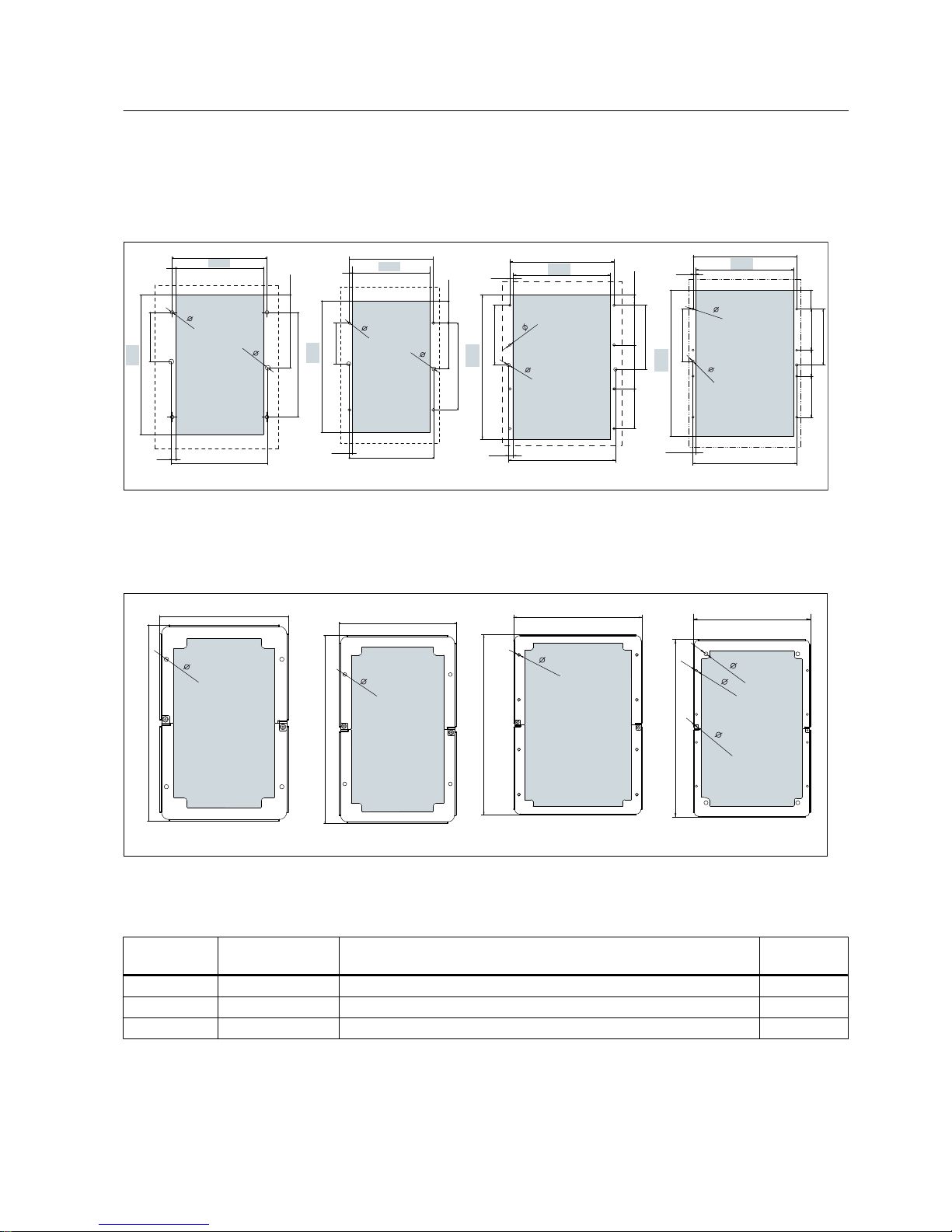
Drill patterns and cut-out dimensions
Please drill holes and cut out an opening in cabinet wall according to the data specified in the
figure below:
)UDPH6L]H$)UDPH6L]H%)UDPH6L]H&)UDPH6L]H'
154
142
156.8
7.4
6
227
80
90
170
28.5
2- 8
4- 6
&XWRXWDUHD
152
164
257
80
170
43.5
90
&XWRXWDUHD
6
2- 8
4- 6
&XWRXWDUHD
166.8
7.4
8- 6
220
7.9
235.8
327
90 90
99.4
23.8
&XWRXWDUHD
242.3
11.1
135.2
145.2
2- 8
262
8
278
392
51
110
150
110
70
&XWRXWDUHD
278.7
8.3
140
2- 8
8- 6
Figure 5-7 Drill pattern and cut-out dimensions (in mm)
Outline dimensions of optional mounting kits
)UDPH6L]H$VSHFLILF)UDPH6L]H%VSHFLILF)UDPH6L]H&VSHFLILF)UDPH6L]H'VSHFLILF
257.6
361
8- 5.8
2- 4.1
4- 10
294
445
172
262
4- 5.8
182
292
4- 5.8
4- 5.8
Figure 5-8 Outline dimensions of optional mounting kits (in mm)
Table 5-3 Mounting torque requirements
Inverter
variant
Holes to be drilled
in cabinet wall
Fixing method Tightening
torque (Nm)
Frame Size A 6 4 x M5 screws and nuts; 2 x plastic rivets 2.5
Frame Size B 6 4 x M5 screws and nuts; 2 x plastic rivets 2.5
Frame Size C 10 8 x M5 screws and nuts; 2 x plastic rivets 2.5
Installation
5.1 Mechanical installation
SINAMICS V10
Operating Instructions, 08/2011, A5E03453178 (this is not an order number) 27

Inverter
variant
Holes to be drilled
in cabinet wall
Fixing method Tightening
torque (Nm)
Frame Size D 10 4 x M8 screws and nuts (for fixing the inverter to the push-through
mounting kit) ; 2 x plastic rivets
2.5
8 x M5 screws and nuts (for fixing the inverter to cabinet wall) 2.5
4 x M4 screws (for fixing the metal back cover to the back of inverter) 0.8
Installation
5.1 Mechanical installation
SINAMICS V10
28 Operating Instructions, 08/2011, A5E03453178 (this is not an order number)

Mounting sequence
Proceed the following procedure to complete your mounting of the inverter with optional
mounting kit through cabinet wall:
Installation
5.1 Mechanical installation
SINAMICS V10
Operating Instructions, 08/2011, A5E03453178 (this is not an order number) 29
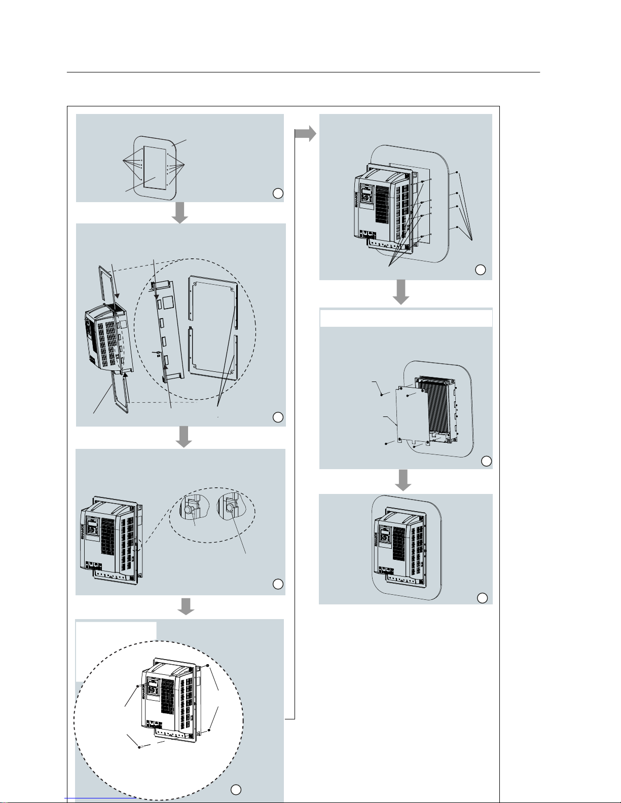
Cabinet wall
Wall cut-out
Mounting holes
Mounting
holes
Make a cut-out in the cabinet wall and drill holes in the wall.
Insert the plastic rivets into the fully overlapped holes of the
mating parts of the push-through mounting kit to interlock
both parts in place.
Slide in the direction of the arrow head each part of the
mounting kit into the mounting slot of the inverter housing
until both parts are well engaged.
Push-through mounting kit
Put this side toward
inverter front
View after locking
Plastic rivet
Mount the inverter to the mounting
kit and tighten the 4 x M8 mounting
screws and screw nuts.
4 x M8 mounting
screws (Tightening
torque: 2.5 Nm)
4 x M8
screw nuts
Mounting the inverter to the cabinet wall, then
tighten the mounting screws and screw nuts
delivered with the product.
Screw
nuts
Mounting screws
This step is necessary
only when mounting
Frame Size D.
06FUHZ
0HWDOEDFNFRYHU
,IQHFHVVDU\XVLQJIRXU0VFUHZVPRXQWWKH
PHWDOEDFNFRYHUWRWKHEDFNRILQYHUWHUWRLPSURYH
FRROLQJHIIHFW
This step is also necessary only when mounting
Frame Size D.
Installation
5.1 Mechanical installation
SINAMICS V10
30 Operating Instructions, 08/2011, A5E03453178 (this is not an order number)
 Loading...