

Siemens SINAMICS SM120 Operating Instructions Manual

Answers for industry.
SINAMICS SM120
Control Module
Type 6SL38715
Operating Instructions / Installation Instructions
Edition 07/2015

30.07.2015 09:23
V4.00

Control Module
SINAMICS SM120
6SL38715
Introduction
1
Operating Instructions
Installation Instructions
Safety instructions
Description
Preparations for use
Assembly
Electrical connection
Commissioning
Operation
2
3
4
5
6
7
8
Maintenance
Spare parts
Disposal
Service & Support
Technical data and drawings
Additional documents
9
10
11
A
B
C
Edition 07/2015

Legal information
Warning notice system
This manual contains notices you have to observe in order to ensure your personal safety, as well as to prevent
damage to property. The notices referring to your personal safety are highlighted in the manual by a safety alert
symbol, notices referring only to property damage have no safety alert symbol. These notices shown below are
graded according to the degree of danger.
DANGER
indicates that death or severe personal injury will result if proper precautions are not taken.
WARNING
indicates that death or severe personal injury may result if proper precautions are not taken.
CAUTION
indicates that minor personal injury can result if proper precautions are not taken.
NOTICE
indicates that property damage can result if proper precautions are not taken.
If more than one degree of danger is present, the warning notice representing the highest degree of danger will be
used. A notice warning of injury to persons with a safety alert symbol may also include a warning relating to property
damage.
Qualified Personnel
The product/system described in this documentation may be operated only by personnel qualified for the specific
task in accordance with the relevant documentation, in particular its warning notices and safety instructions. Qualified
personnel are those who, based on their training and experience, are capable of identifying risks and avoiding
potential hazards when working with these products/systems.
Proper use of Siemens products
Note the following:
WARNING
Siemens products may only be used for the applications described in the catalog and in the relevant technical
documentation. If products and components from other manufacturers are used, these must be recommended or
approved by Siemens. Proper transport, storage, installation, assembly, commissioning, operation and
maintenance are required to ensure that the products operate safely and without any problems. The permissible
ambient conditions must be complied with. The information in the relevant documentation must be observed.
Trademarks
All names identified by ® are registered trademarks of Siemens AG. The remaining trademarks in this publication
may be trademarks whose use by third parties for their own purposes could violate the rights of the owner.
Disclaimer of Liability
We have reviewed the contents of this publication to ensure consistency with the hardware and software described.
Since variance cannot be precluded entirely, we cannot guarantee full consistency. However, the information in
this publication is reviewed regularly and any necessary corrections are included in subsequent editions.
Siemens AG
Process Industries and Drives
Postfach 48 48
90026 NÜRNBERG
GERMANY
Order number: SM120 Control Module
Ⓟ 07/2015 Subject to change
Copyright © Siemens AG 2013, -, 2015.
All rights reserved

Table of contents
1 Introduction.................................................................................................................................................11
1.1 About these instructions.........................................................................................................11
1.2 Warning symbols on the device.............................................................................................12
2 Safety instructions......................................................................................................................................13
2.1 Qualified personnel................................................................................................................13
2.2 The five safety rules...............................................................................................................13
2.3 Safe handling.........................................................................................................................14
2.4 Electromagnetic fields in electrical power engineering installations ......................................16
2.5 Components that can be destroyed by electrostatic discharge (ESD)...................................17
2.6 Information for persons responsible for plants and systems..................................................19
2.6.1 Proper usage..........................................................................................................................19
2.6.2 Industrial security concept......................................................................................................20
2.6.3 Grounding concept.................................................................................................................21
2.6.4 Installation site safety.............................................................................................................21
2.6.5 Instructions for inverters with no grounding switch................................................................22
2.6.6 Measures for operator protection in electromagnetic fields...................................................22
2.6.7 Requirements for the circuit breaker provided by the customer.............................................22
2.7 Residual risks.........................................................................................................................23
3 Description..................................................................................................................................................27
3.1 Safety concept.......................................................................................................................27
3.1.1 Safety components and functions..........................................................................................27
3.1.2 External safety components...................................................................................................27
3.1.3 Protection and monitoring functions of internal components.................................................28
3.1.4 Protection and monitoring functions for external components...............................................28
3.2 Control Module.......................................................................................................................28
3.3 Components...........................................................................................................................29
3.3.1 AOP30 operator panel...........................................................................................................29
3.3.2 Control Unit............................................................................................................................30
3.3.3 Terminal Modules...................................................................................................................31
3.3.4 Voltage Sensing Module........................................................................................................31
3.3.5 DC/DC converter....................................................................................................................32
3.3.6 Line filter.................................................................................................................................32
3.3.7 Sirius safety relay...................................................................................................................33
3.3.8 Auxiliary power supply...........................................................................................................33
3.3.8.1 Auxiliary power supply 1AC 230V 50Hz.................................................................................33
3.3.8.2 Auxiliary power supply 400V 3 AC 50Hz................................................................................34
3.3.9 Customer terminal strips........................................................................................................34
3.4 Options...................................................................................................................................34
3.4.1 Auxiliary voltage supply 3 AC 200 V 50 Hz (option C30).......................................................34
SINAMICS SM120 6SL38715
Operating Instructions 07/2015 5

Table of contents
3.4.2 Auxiliary voltage supply 3 AC 220 V 60 Hz (option C33).......................................................34
3.4.3 Auxiliary voltage supply 3 AC 230 V 60 Hz (option C34).......................................................35
3.4.4 Auxiliary voltage supply 3 AC 240 V 60 Hz (option C35).......................................................35
3.4.5 Auxiliary voltage supply 3 AC 380 V 50 Hz (option C36).......................................................35
3.4.6 Auxiliary voltage supply 3 AC 380 V 60 Hz (option C37).......................................................35
3.4.7 Auxiliary voltage supply 3-phase 400 VAC 50 Hz (option C38).............................................36
3.4.8 Auxiliary voltage supply 3 AC 415 V 50 Hz (option C39).......................................................36
3.4.9 Auxiliary voltage supply 3 AC 440 V 60 Hz (option C40).......................................................36
3.4.10 Auxiliary voltage supply 3 AC 460 V 60 Hz (option C41).......................................................36
3.4.11 Auxiliary voltage supply 3 AC 480 V 60 Hz (option C42).......................................................36
3.4.12 Auxiliary voltage supply 3 AC 500 V 50 Hz (option C43).......................................................37
3.4.13 Auxiliary voltage supply 3 AC 550 V 50 Hz (option C44).......................................................37
3.4.14 Auxiliary voltage supply 3 AC 575 V 60 Hz (option C46).......................................................37
3.4.15 Auxiliary voltage supply 3 AC 690 V 50 Hz (option C48).......................................................37
3.4.16 Auxiliary voltage supply 3 AC 690 V 60 Hz (option C49).......................................................38
3.4.17 Suitable for marine use with individual certificate from Germanischer Lloyd (GL) (option
E11)........................................................................................................................................38
3.4.18 Suitable for marine use with individual certificate from Lloyds Register (LR) (option E21)......38
3.4.19 Suitable for marine use with individual certificate from Bureau Veritas (BV) (option E31)......38
3.4.20 Suitable for marine use with individual certificate from Det Norske Veritas (DNV) (option
E51)........................................................................................................................................38
3.4.21 Suitable for marine use with individual certificate from American Bureau of Shipping
(ABS) (option E61).................................................................................................................38
3.4.22 Suitable for marine use with individual certificate from Chinese Classification Society
(CCS) (option E71).................................................................................................................39
3.4.23 Can Bus interface (option G20)..............................................................................................39
3.4.24 CBE20 communications card for PROFINET (option G24)...................................................39
3.4.25 Modbus RTU Slave interface (option G22)............................................................................39
3.4.26 DeviceNet interface (option G23)...........................................................................................39
3.4.27 Modbus Ethernet interface (option G28)................................................................................40
3.4.28 1x temperature sensor evaluation unit TM150 (option G51)..................................................40
3.4.29 2x temperature sensor evaluation units TM150 (option G52)................................................40
3.4.30 3x temperature sensor evaluation units TM150 (option G53)................................................40
3.4.31 4x temperature sensor evaluation units TM150 (option G54)................................................40
3.4.32 Terminal Module TM31 (option G61).....................................................................................40
3.4.33 Second Terminal Module TM31 (option G62)........................................................................41
3.4.34 Additional Terminal Module TM15 (option G63)....................................................................41
3.4.35 Pulse distributor for splitting speed encoder signal (option G70)...........................................42
3.4.36 Optical bus terminal (OBT) for PROFIBUS (option G71).......................................................42
3.4.37 Indicator lamps in the cabinet door (option K20)....................................................................42
3.4.38 Display instruments in the cabinet door for voltage, current, speed, and output plus
indicator lamps (option K21)..................................................................................................42
3.4.39 Sensor Module SMC30 (option K50).....................................................................................43
3.4.40 Automatic restart function (option L32)..................................................................................43
3.4.41 Emergency mushroom-head pushbutton (option L45)...........................................................44
3.4.42 Cabinet lighting in the control section (option L50)................................................................44
3.4.43 Uninterruptible power supply (option L53).............................................................................45
3.4.44 Anti-condensation heating (option L55).................................................................................45
3.4.45 EMERGENCY STOP Category 0; 24 VDC (option L66)........................................................46
3.4.46 Signal and control cable (max. 2.5 mm²) (option M33)..........................................................46
3.4.47 Connection of auxiliary voltage and signal cable from above (option M34)...........................46
3.4.48 Degree of protection IP44 (option M44).................................................................................46
SINAMICS SM120 6SL38715
6 Operating Instructions 07/2015

Table of contents
3.4.49 Suitability for marine use (option M66)...................................................................................46
3.4.50 Controlled outgoing circuit for motor fan 3-phase 400 VAC (option N30)..............................47
3.4.51 Controlled outgoing circuit for motor fan 3-phase 460/480 VAC (option N31).......................47
3.4.52 Controlled outgoing circuit for anti-condensation heating 1-phase 230 VAC (option N35)......47
3.4.53 Controlled outgoing circuit for anti-condensation heating 1-phase 230 VAC (option N36)......47
3.4.54 Controlled outgoing circuit for anti-condensation heating 1-phase 120 VAC (option N37)......48
4 Preparations for use...................................................................................................................................49
4.1 Requirements for installation location....................................................................................49
4.2 Inspections when the equipment is received.........................................................................49
4.2.1 Checking the delivery.............................................................................................................49
4.2.2 Checking shock and tilt indicators..........................................................................................50
4.2.3 Checking the load handling attachments...............................................................................53
4.3 Transport................................................................................................................................53
4.3.1 Transport markings................................................................................................................53
4.3.2 Transport requirements..........................................................................................................54
4.3.3 Take the center of gravity into account..................................................................................54
4.3.4 Transport with a fork-lift truck.................................................................................................55
4.3.5 Transport with a crane...........................................................................................................55
4.3.6 Using lifting rods.....................................................................................................................56
4.3.7 Transporting transportation units packed in boxes................................................................57
4.4 Unpacking the cabinets..........................................................................................................58
4.4.1 Removing the packaging........................................................................................................58
4.4.2 Removing load securing devices...........................................................................................59
4.4.3 Lifting the cabinet off the transport pallet...............................................................................59
4.4.4 Checking the shock and tilt indicators inside the cabinet.......................................................59
4.5 Storage...................................................................................................................................60
4.5.1 Storing a device.....................................................................................................................60
5 Assembly....................................................................................................................................................63
5.1 Safety instructions for assembly............................................................................................63
6 Electrical connection...................................................................................................................................65
6.1 Safety instructions for electrical connections.........................................................................65
6.2 Electromagnetic compatibility.................................................................................................67
6.3 Potential concept....................................................................................................................70
6.4 Cable cross-sections..............................................................................................................70
6.5 Connecting ground.................................................................................................................71
6.6 Laying the signal lines............................................................................................................71
6.7 Connecting the auxiliary voltage............................................................................................72
6.8 Interconnecting optional connections.....................................................................................72
6.9 Fastening the cable ducts with cable ties...............................................................................73
7 Commissioning...........................................................................................................................................75
8 Operation....................................................................................................................................................77
8.1 Safety instructions for operation.............................................................................................77
SINAMICS SM120 6SL38715
Operating Instructions 07/2015 7

Table of contents
8.2 Functions................................................................................................................................78
8.2.1 Monitoring functions and protective functions........................................................................78
8.2.1.1 Insulation monitoring..............................................................................................................78
8.2.1.2 Tripping of the circuit-breaker in case of undervoltage..........................................................79
8.3 Fault and system messages..................................................................................................80
8.3.1 Indicating and rectifying faults................................................................................................80
8.3.2 Diagnostics via LEDs.............................................................................................................81
8.3.2.1 LEDs of the Sirius safety relay...............................................................................................81
9 Maintenance...............................................................................................................................................83
9.1 Safety instructions for maintenance.......................................................................................83
9.2 Grounding the system............................................................................................................85
9.2.1 Grounding using the grounding harness................................................................................85
9.3 Opening the device................................................................................................................86
9.4 Preventive maintenance.........................................................................................................86
9.4.1 Inspection...............................................................................................................................86
9.4.2 Checklist for preventive maintenance work............................................................................87
9.4.3 Visual inspections..................................................................................................................87
9.4.3.1 Equipment for visual inspections............................................................................................87
9.4.3.2 Checking hoisting solenoids and security bolts......................................................................88
9.4.3.3 Checking the plug connections..............................................................................................88
9.4.3.4 Checking the cable and screw terminals................................................................................88
9.5 Maintenance...........................................................................................................................88
9.5.1 Replacing the back-up battery of the AOP30 operator panel ................................................88
9.5.2 Loading operator panel firmware, parameter and signal descriptions...................................90
9.6 Cleaning.................................................................................................................................91
9.6.1 Removing dust deposits.........................................................................................................91
9.6.2 Cleaning aluminum parts.......................................................................................................91
9.7 Repair.....................................................................................................................................92
9.7.1 Reference to the safety instructions section..........................................................................92
9.7.2 Components that can be replaced.........................................................................................93
9.7.3 Torques..................................................................................................................................94
9.7.4 Replacing the AOP30 operator panel....................................................................................95
9.7.5 Replacing the CompactFlash card.........................................................................................96
10 Spare parts.................................................................................................................................................97
11 Disposal......................................................................................................................................................99
11.1 Disposing of packaging material............................................................................................99
11.2 Removing device components and old devices.....................................................................99
A Service & Support.....................................................................................................................................101
A.1 Siemens Industry Online Support........................................................................................101
B Technical data and drawings....................................................................................................................103
B.1 Standards and regulations...................................................................................................103
B.2 Environmental conditions.....................................................................................................103
SINAMICS SM120 6SL38715
8 Operating Instructions 07/2015

Table of contents
B.3 Plant-specific information.....................................................................................................104
C Additional documents...............................................................................................................................105
Index.........................................................................................................................................................107
Tables
Table 6-1 Cable cross-sections...................................................................................................................70
Table 8-1 LEDs of the Sirius safety relay ...................................................................................................81
Table 9-1 Control Module: Checklist for preventive maintenance work......................................................87
Table 9-2 Technical specifications of the backup battery............................................................................88
Table 9-3 Tightening torques in Nm............................................................................................................94
Table B-1 Standards and regulations........................................................................................................103
Table B-2 Climatic environmental conditions.............................................................................................103
Table B-3 Mechanical ambient conditions.................................................................................................104
Table B-4 Other ambient conditions..........................................................................................................104
Figures
Figure 2-1 ESD protective measures ...........................................................................................................18
Figure 3-1 AOP30 operator panel.................................................................................................................29
Figure 3-2 DC/DC converter.........................................................................................................................32
Figure 3-3 Line filter......................................................................................................................................32
Figure 3-4 SIRIUS safety relay.....................................................................................................................33
Figure 4-1 Example for attaching shock and tilt indicators...........................................................................51
Figure 4-2 Example illustration of centers of gravity.....................................................................................54
Figure 4-3 Lifting rod label............................................................................................................................57
Figure 4-4 Securing the lifting rods...............................................................................................................57
Figure 4-5 Transporting a transportation unit (still in packaging) with a crane.............................................58
Figure 6-1 Shield connection using a clip.....................................................................................................69
Figure 6-2 Bridging shield gaps....................................................................................................................69
Figure 6-3 Potential concept.........................................................................................................................70
Figure 6-4 Fastening the cable ties..............................................................................................................73
Figure 9-1 Replacing the backup battery......................................................................................................89
Figure 9-2 Replacement of the AOP30 operator panel................................................................................95
SINAMICS SM120 6SL38715
Operating Instructions 07/2015 9

Table of contents
SINAMICS SM120 6SL38715
10 Operating Instructions 07/2015

Introduction
1.1 About these instructions
These instructions describe the drive and explain how to handle it, from initial delivery to final
disposal of the equipment. Keep these instructions for later use.
Read these instructions before you handle the drive and follow the instructions. The
instructions contain information about the safe handling of the drive as well as its components
and modules. They provide information on assembling, installing, and maintaining the
equipment properly.
If you have suggestions for improving the document, please contact our Service Center
(Page 101).
Note
In these instructions, the term "Drive" is used, even if individual cabinet modules are involved.
Text format features
The warning notice system is explained on the rear of the inside front. Always follow the safety
instructions and notices in these instructions.
1
In addition to the safety-related warning notices which you must read, you will find the text in
these instructions is formatted in the following way:
1. Handling instructions are always formatted as a numbered list. Always perform the steps
in the order given.
● Lists are formatted as bulleted lists.
– Lists on the second level are hyphenated.
Note
A Note is an important item of information about the product, handling of the product or the
relevant section of the document. Notes provide you with help or further suggestions/ideas.
SINAMICS SM120 6SL38715
Operating Instructions 07/2015 11
Introduction
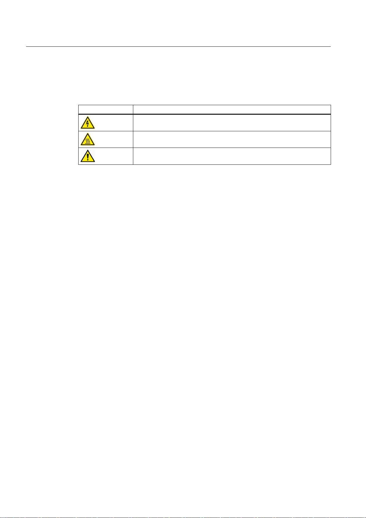
1.2 Warning symbols on the device
1.2 Warning symbols on the device
Please observe the warning symbols attached to the device. The warning symbols have the
following meaning:
Warning symbol Meaning
Warning: Voltage
Warning: Hot surface
General warning symbol: Observe the explanations about the hazard on the
device labels.
For transportation, observe the "transportation markings (Page 53)" on the device packaging.
SINAMICS SM120 6SL38715
12 Operating Instructions 07/2015

Safety instructions
In the individual chapters of this document, you will find safety instructions that must be obeyed
absolutely, for your own safety, to protect other people and to avoid damage to property. Pay
attention to the following safety instructions for all activities on the inverter.
2.1 Qualified personnel
The product/system described in this documentation may only be operated by personnel
qualified for the specific task in accordance with the relevant documentation for the specific
task, in particular its warning notices and safety instructions. Because of their training and
experience, qualified personnel can recognize any risks involved with handling these products/
systems and avoid any possible dangers.
2.2 The five safety rules
For your personal safety and to prevent material damage when carrying out any work, always
observe the safety instructions and the following five safety rules, according to EN 50110‑1
"Dead working". Apply the five safety rules in the sequence stated before starting work.
2
Five safety rules
1. Disconnect completely.
Disconnect the auxiliary circuits, for example anti-condensation heating.
2. Secure against reconnection.
3. Verify absence of operating voltage.
4. Carry out earthing and short-short-circuiting.
5. Provide protection against adjacent live parts.
To energize the system, apply the measures in reverse order.
SINAMICS SM120 6SL38715
Operating Instructions 07/2015 13

Safety instructions
2.3 Safe handling
2.3 Safe handling
WARNING
High voltages from external supplies
Even if the circuit breaker is open, parts of the drive can be under voltage (live) as a result of
the auxiliary voltage at the premagnetization, precharging or demagnetization transformers.
This danger is not limited to the drive, but can also occur with components that are electrically
connected to the drive (e.g. circuit breakers or isolators). Touching live components can result
in death, serious injury, or material damage.
Therefore, isolate all components that can feed voltage to the drive before commencing work.
WARNING
High voltages during operation
When operating this equipment very high voltages develop. Even after switching off the mains
voltage, or while the connected machine is still turning, high voltages can remain for a
prolonged length of time. High voltages can cause death or serious injury if the safety rules
are not observed or if the equipment is handled incorrectly.
● Operate the drive properly.
● Always follow the "The five safety rules (Page 13)" when performing any work.
● Only remove the covers using the methods described by these operating instructions.
● Maintain the drive regularly and correctly.
WARNING
High voltages from machines still turning and connected
Rotating machinery can induce dangerous high voltages and synchronous motors that are
not de-excited immediately can also pose a hazard. If the connection to the motor is not
isolated or grounded, these voltages can also remain. If live parts are touched, this can result
in death and serious physical injuries.
Before opening the doors, wait until the connected machine has come to a standstill.
WARNING
High voltages from DC-link capacitors
High voltages are still present at the DC-link capacitors even after shutdown. If live parts are
touched, this can result in death or serious physical injury.
● Wait for the DC-link capacitor's discharge time specified on the device label. Do not touch
the device during this time.
● Observe the five safety rules when performing any work.
SINAMICS SM120 6SL38715
14 Operating Instructions 07/2015

Safety instructions
2.3 Safe handling
WARNING
High auxiliary voltages
High auxiliary voltages are still present even after shutdown. If live parts are touched, this
can result in death or serious physical injury.
Observe the five safety rules when performing any work.
WARNING
Hazardous arcing
Hazards caused by arcing can occur as result of the following factors, for example:
● The input currents are exceeded
● Incorrectly dimensioned circuit breaker or transformers
● Incorrectly connected cables or cables that have not been connected
● Excessive pollution
Arcing can result in death, serious injury or material damage.
● Make sure that the system is properly dimensioned and that the power cables are correctly
connected. The maximum permissible input currents are listed in the "Technical
specifications".
● Remove any excessive pollution.
WARNING
Live, moving or rotating parts
Contact with the parts mentioned can result in death, serious physical injury or damage to
property.
● Observe the instructions regarding installation and operation.
● Always take protective measures before touching any components.
● Do not remove any necessary covers.
WARNING
Hot component surfaces
Certain components (e.g. heat sinks and reactors) can become very hot during operation.
These components can remain hot for a long time after operation. Contact can result in serious
injury, such as skin burns.
Do not touch hot components even after you have switched off the drive.
SINAMICS SM120 6SL38715
Operating Instructions 07/2015 15

Safety instructions
2.4 Electromagnetic fields in electrical power engineering installations
WARNING
Hot anti-condensation heating surface
When the temperature control limit value is reached the anti-condensation heating is switched
on. Once activated, the anti-condensation heating can generate a great deal of heat. Contact
can result in serious injury, such as skin burns.
Do not touch the anti-condensation heating.
CAUTION
Places that are difficult to access
If you do not use appropriate protective equipment when working in places that are difficult
to access you are at risk of injury. For example, sharp edges and splinters can cause injuries
to the head and skin. If you use unsuitable steps when working on the upper areas of the
drive, you can fall and injure yourself.
● Use appropriate protective equipment, especially a hard hat and gloves.
● In the upper areas of the drive, use suitable steps.
NOTICE
Unsuitable residual current monitoring device
If you operate the drive together with a residual current monitoring device (RCD), it is possible
the residual current monitoring device will trip in error (nuisance trip). The drive may be
switched off as a result of the protection device tripping in error.
To minimize the risk of faulty trips, use a type-B RCD.
2.4 Electromagnetic fields in electrical power engineering installations
Electromagnetic fields are generated during operation of electrical power engineering
installations. Electromagnetic fields can interfere with electronic devices, These devices can
malfunction if electromagnetic fields are present.
WARNING
Interference with pacemakers
The functioning of cardiac pacemakers could be impaired by electromagnetic fields. Death
or serious physical injury can result.
People with pacemakers are therefore not allowed to stay close to the drive.
SINAMICS SM120 6SL38715
16 Operating Instructions 07/2015

Safety instructions
2.5 Components that can be destroyed by electrostatic discharge (ESD)
NOTICE
Data loss
Electromagnetic fields can cause data loss to magnetic or electronic data storage media.
Therefore, do not carry magnetic or electronic data storage media with you.
For nominated persons in control of an electrical installation, you can find further information
on electromagnetic fields under "Information for nominated persons in control of an electrical
installation."
See also
Information for persons responsible for plants and systems (Page 19)
2.5 Components that can be destroyed by electrostatic discharge (ESD)
ESD guidelines
NOTICE
Electrostatic discharge
Electronic components can be destroyed in the event of improper handling, transporting,
storage, and shipping.
Pack the electronic components in appropriate ESD packaging; e.g. ESD foam, ESD
packaging bags and ESD transport containers.
To protect your equipment against damage, follow the instructions given below.
● Avoid physical contact with electronic components. If it is essential that you perform work
on these components, then you must wear one of the following pieces of protective gear:
– Grounded ESD wrist strap
– ESD shoes or ESD shoe grounding strips if there is also an ESD floor.
● Do not place electronic components close to data terminals, monitors or televisions.
Maintain a minimum clearance to the screen (> 10 cm).
● Electronic components should not be brought into contact with electrically insulating
materials such as plastic foil, plastic parts, insulating table supports or clothing made of
synthetic fibers.
SINAMICS SM120 6SL38715
Operating Instructions 07/2015 17
Safety instructions
2.5 Components that can be destroyed by electrostatic discharge (ESD)
● Bring components into contact only with ESD-compliant materials, e.g. ESD tables, ESD
surfaces, ESD packaging.
● Only carry out measurements on the components if one of the following conditions is met:
– The measuring device is grounded with a protective conductor, for example.
– The measuring head of a floating measuring device has been discharged directly before
the measurement.
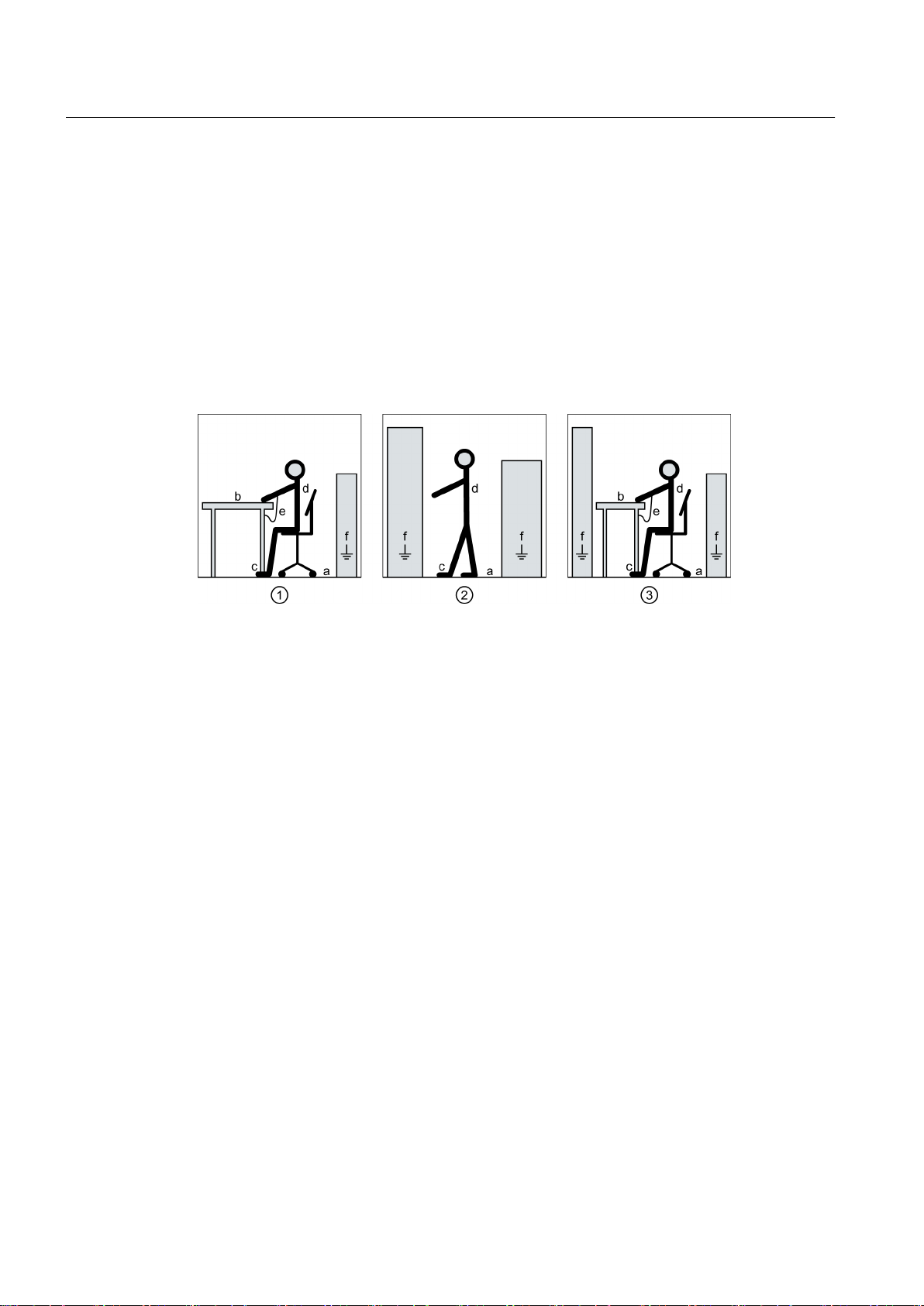
The necessary ESD protective measures for the entire working range for electrostatically
sensitive devices are illustrated once again in the following drawings.
Precise instructions for ESD protective measures are specified in the standard
DIN EN 61340‑5‑1.
① Sitting
② Standing
③ Standing/sitting
a Conductive floor surface, is only effective in conjunction with ESD shoes or ESD shoe grounding
strips
b ESD furniture
c ESD shoes or ESD shoe grounding strips are only effective in conjunction with conductive flooring
d ESD clothing
e ESD wrist strap
f Cabinet ground connection
Figure 2-1 ESD protective measures
SINAMICS SM120 6SL38715
18 Operating Instructions 07/2015

Safety instructions
2.6 Information for persons responsible for plants and systems
2.6 Information for persons responsible for plants and systems
2.6.1 Proper usage
The drives are intended to be used as a stationary installation in closed and dry rooms with a
clean atmosphere. You can find the environmental and operating temperatures that are to be
adhered to in the technical specifications. If the described environmental conditions are not
complied with, then warranty claims and other claims may be rejected.
WARNING
Explosions
If you operate the drive in areas with a risk of explosion, explosions can occur which can
cause death, serious injuries or material damage.
Only operate the converter in a non-explosive environment (no hazardous zones).
WARNING
Non-observance of proper usage
Improper use of the devices described can result in death, severe injury or material damage.
Therefore, please adhere to all instructions for proper usage.
The nominated person in control of an electrical installation must ensure that the following
points are observed:
● Follow the local and industry-specific safety and setup regulations. Observe the
requirements listed in the directives, specified in the "Technical specifications" in Section
"Standards and regulations". Ensure that the specific safety and construction regulations
and regulations for using personal protective equipment are adhered to during all work.
● The operating instructions and the complete product documentation are always available
when carrying out any work.
● The technical specifications as well as the specifications relating to the permissible
installation, connection, ambient and operating conditions are taken into account at all times.
● Only qualified personnel or personnel supervised by responsible, skilled specialists are
allowed to carry out basic planning and all work on the drive.
● During shipping, specific transport conditions are adhered to.
● Assembly is performed according to assembly instructions. Separate cabinet units are
connected properly (cables and busbars).
● All instructions for EMC-compatible installation, cabling, shielding, grounding, and for
adequate auxiliary power supply are to be observed.
● Commissioning is only to be performed by qualified personnel trained for that purpose in
accordance with the commissioning instructions.
SINAMICS SM120 6SL38715
Operating Instructions 07/2015 19

Safety instructions
2.6 Information for persons responsible for plants and systems
● System configuration is carried out by an experienced system integrator. Further system
components such as the circuit-breaker, transformer, cables, and motor are adjusted for
drive operation.
● The drive is only operated in conjunction with the engineered components.
● Different operating modes, overloads, load cycles, and differing environmental conditions
are permitted only after special arrangement with the manufacturer.
Note
Make use of the support and services offered by the relevant service center for planning,
installation, commissioning, and servicing work. You can find the relevant contact person under
"Service & Support (Page 101)".
2.6.2 Industrial security concept
Siemens provides products and solutions with industrial security functions that support the
secure operation of plants, solutions, machines, devices, and/or networks. They are important
components in a holistic industrial security concept. The products and solutions from Siemens
are continuously developed with this aspect in mind. Siemens strongly recommends that you
regularly check for product updates.
To ensure that Siemens products and solutions are operated securely, suitable preventive
measures (e.g. cell protection concept) must be taken and each component must be integrated
into a state-of-the-art holistic industrial security concept. Any third-party products used must
also be taken into account. For more information about industrial security, visit http://
www.siemens.com/industrialsecurity (http://www.siemens.com/industrialsecurity)
To receive information about product updates on a regular basis, subscribe to our product
newsletter. For more information, visit http://support.automation.siemens.com (http://
support.automation.siemens.com)
SINAMICS SM120 6SL38715
20 Operating Instructions 07/2015

2.6.3 Grounding concept
Create a grounding concept and integrate the drive within it. The grounding concept must take
into consideration national provisions and system specifics. Ensure that the following criteria
are fulfilled:
● The drive sub-units must be screwed together with good conductivity on the construction
site.
● If grounding bars are provided, these must be connected together.
● When the drive is supplied with power, the protective earth conductor must be connected
to the system's grounding point. Select the cross-section of the protective ground conductor
from one of the following variants:
– According to local wiring regulations
– Calculated according to IEC 60364-5-54, 543.1
– Half a phase conductor cross-section
2.6.4 Installation site safety
Safety instructions
2.6 Information for persons responsible for plants and systems
WARNING
Unsafe installation sites
This drive is used in industrial high-voltage installations. Improper use, incorrect operation,
insufficient maintenance, and access by unauthorized persons can lead to accidents. The
results can be death, serious bodily injury or damage to property.
● Install the drive in electrical rooms where only qualified personnel have access. If this is
not possible, then ensure that a barrier prevents uncontrolled access. Use safety fences
and appropriate signs, for example, to prevent unauthorized entry to the zone that has
been fenced off.
● Put up notices which indicate that only trained personnel are allowed to operate the drive
and carry out maintenance and repair work.
Note
Installations that include drive drives need to be equipped with additional monitoring and
protection equipment to fulfill the safety requirements, e.g. technical equipment regulations,
accident prevention regulations, etc.
SINAMICS SM120 6SL38715
Operating Instructions 07/2015 21

Safety instructions
2.6 Information for persons responsible for plants and systems
2.6.5 Instructions for inverters with no grounding switch
Note
The drive does not have a grounding breaker at the input/output. The system operator must,
therefore, ensure that there is sufficient grounding.
2.6.6 Measures for operator protection in electromagnetic fields
The plant operator is responsible for taking the following appropriate measures (labels and
hazard warnings) to adequately protect operating personnel against any possible risk.
● Observe the relevant nationally applicable health and safety regulations or the applicable
national regulations in the country of installation. In Germany, "electromagnetic fields" are
subject to regulations BGV B11 and BGR B11 stipulated by the German statutory industrial
accident insurance institution.
● Display adequate hazard warning notices on the installation.
● Place barriers around hazardous areas.
● Take measures, e.g. using shields, to reduce electromagnetic fields at their source.
● Make sure that personnel are wearing the appropriate protective gear.
2.6.7 Requirements for the circuit breaker provided by the customer
The circuit breaker on the primary side of the input transformer on the plant side belongs to
the safety system of the drive. If a fault occurs inside the drive, the energy that is effective at
the fault location must be limited. This is realized as a result of the inductance of the incoming
transformer, which limits the rate-of-rise and magnitude of the current and the circuit breaker
that trips as quickly as possible.
WARNING
High voltages and arcs
Circuit breakers are safety components. Connecting or setting the circuit breaker incorrectly
can result in death, serious injury, or material damage.
Connect the circuit breakers correctly. Select the system values that match the drive.
SINAMICS SM120 6SL38715
22 Operating Instructions 07/2015

Safety instructions
2.7 Residual risks
To ensure adequate drive protection, the circuit breaker provided by the customer must fulfill
the following requirements:
● The total opening time of the circuit breaker – from the command to actually opening – must
not be more than 80 ms. It is not permissible that the opening time, specified in the technical
documentation of the circuit breaker manufacturer, exceeds 80 ms. The drive monitors the
total opening time.
● The drive monitors the TRIP coils (shunt releases) for wire breakage and failure of the
control voltage in the switchgear installation.
● The circuit breaker must be equipped with an undervoltage tripping function. The
undervoltage trip unit (low-voltage coil) is controlled via the tripping circuit in which the
"undervoltage trip unit" of the drive must also be integrated. The auxiliary voltage from the
switchgear (this is a reliable supply) is used as the supply.
● Avoid additional delay times when controlling the circuit breaker. All commands from the
drive to the circuit breaker must act directly without intervention of coupling relays.
● A feedback signal must be available for each of the circuit breaker states CLOSED and
OPEN. The feedback signals must not be delayed. Do not use any coupling relays.
● An additional, independently operating overcurrent protection for the circuit breaker must
be provided on the plant side (transformer and cable protection).
● The circuit breaker is activated and enabled by the drive closed-loop controller. Under no
circumstances should you close the circuit breaker by external mechanical or electrical
means. A mechanical interlock of the manual ON command at the circuit breaker prevents
destruction of the drive as a result of an uncoordinated switch-on operation.
2.7 Residual risks
According to the EU machinery directive, machine manufacturers / plant operators must
conduct a risk assessment of their machine. Plant operators must conduct a risk assessment
of their plant. In particular, pay attention to Annex 1 "General Principles" of the EU machinery
directive.
SINAMICS SM120 6SL38715
Operating Instructions 07/2015 23

Safety instructions
2.7 Residual risks
Pay attention to the following residual risks:
1. Unintentional movements of driven machine parts
Unintentional movements of driven machine parts can occur during commissioning,
operation, maintenance, and repair, e.g. from the following causes:
– Hardware defects and/or software errors in the sensors, controllers, actuators, and
connection technology
– Response times of the controller and drive
– Operating and/or environmental conditions outside of the specification
– Condensation/conductive contamination
– Parameterization, programming, cabling, and installation errors
– Use of radio devices/cellular phones in the immediate vicinity of the controller
– External influences/damage
2. High temperatures and emissions
A fault can occur as a result of the following, for example:
– Component malfunctions
– Software errors
– Operating and/or environmental conditions outside of the specification
– External influences/damage
A fault can, for example, have the following consequences both inside and outside the drive:
– Extraordinarily high temperatures, including open fires as a result of the fault
– Emissions of light, noise, particles or gases
Drives with open type / IP20 degree of protection must be installed in an electrical room or
a comparable environment.
3. Hazardous shock voltages
Hazardous shock voltages can result from the following causes, for example:
– Component malfunctions
– Induction of voltages in moving motors
– Operating and/or environmental conditions outside of the specification
– Condensation/conductive contamination
– External influences/damage
4. The release of substances and emissions that are harmful to the environment
Improper operation or the improper disposal of components can harm the environment.
SINAMICS SM120 6SL38715
24 Operating Instructions 07/2015

Safety instructions
2.7 Residual risks
5. Damage from pressure build-up during electric arcs in the event of a fault
If the building has not been designed correctly for the drive in terms of how it has been
dimensioned, damage can result from the pressure that can possibly build up inside.
6. Dangerous electric arcs during internal faults
The drives are designed according to the relevant IEC standards and have been tested in
line with strict type-testing procedures. They were developed and manufactured so that
there is a very low probability of internal faults occurring. However, internal faults cannot
be completely ruled out.
WARNING
Dangerous electric arcs during internal faults
Defects such as damage to components, overvoltages, or loose parts, as well as exceptional
operating statuses, can cause a failure within the enclosure. This can result in an internal
electric arc. If an electric arc occurs and people are nearby, this could lead to death, serious
physical injury, and damage to property.
● Ensure that only qualified personnel perform work on the drive.
● Observe the safety and operating instructions in this documentation and on labels at the
drive for all work on the drive.
Note
There are no standards for medium-voltage drives stipulating requirements or inspections for
electric arc resistance. There is therefore neither formal guidance provided nor formal
certification available with regard to electric arc resistance.
SINAMICS SM120 6SL38715
Operating Instructions 07/2015 25

Safety instructions
2.7 Residual risks
SINAMICS SM120 6SL38715
26 Operating Instructions 07/2015

Description
3.1 Safety concept
The drive and its components are subject to a comprehensive safety concept. When used
properly, the security concept guarantees safe installation, safe operation as well as safe
service and maintenance.
The safety concept encompasses safety components and functions to protect the device and
operators. The drive is also equipped with monitoring functions to protect external components.
The drive operates safely when the interlock and protection systems are functioning properly.
Nevertheless, there are areas on the drive that are hazardous for personnel and that cause
material damage if the safety information of all the instructions and the label on the drive are
not strictly observed.
3.1.1 Safety components and functions
An Emergency mushroom-head pushbutton is installed in the cabinet door of the Control
Module.
3
See also
Emergency mushroom-head pushbutton (option L45) (Page 44)
3.1.2 External safety components
The drive has the following external safety components for the safety concept:
● Circuit breaker
More detailed information is provided in Chapter Requirements for the circuit breaker
provided by the customer (Page 22).
SINAMICS SM120 6SL38715
Operating Instructions 07/2015 27

Description
3.2 Control Module
3.1.3 Protection and monitoring functions of internal components
The internal components of the drive have the following protection and monitoring functions:
● Drive protection based on monitoring systems:
– Current monitoring
– DC link monitoring
– Monitoring the output voltage
– Thermal monitoring of the power unit
– Precharging monitoring
– Supply voltage monitoring
– Insulation monitoring
– Monitoring of the common power supply
– Circuit breaker monitoring
– Re-cooling unit monitoring
● Shutdown in the event of semiconductor failure
● Shutdown in the event of control component failure
● Internal protection functions for the control hardware
● Protection against communication failure between the closed-loop control and the power
unit
● Anti-condensation heating
3.1.4 Protection and monitoring functions for external components
Transformer and motor can be monitored in the drive. A fast protective shutdown that you can
activate for external problems, e.g. short-circuits, is present.
3.2 Control Module
The purpose of the Control Module is for the open-loop and closed-loop control of the drive.
Operating control and diagnostics of the drive are also realized using the Control Module.
Note
Details on the design can be found in the layout diagram.
SINAMICS SM120 6SL38715
28 Operating Instructions 07/2015
3.3 Components
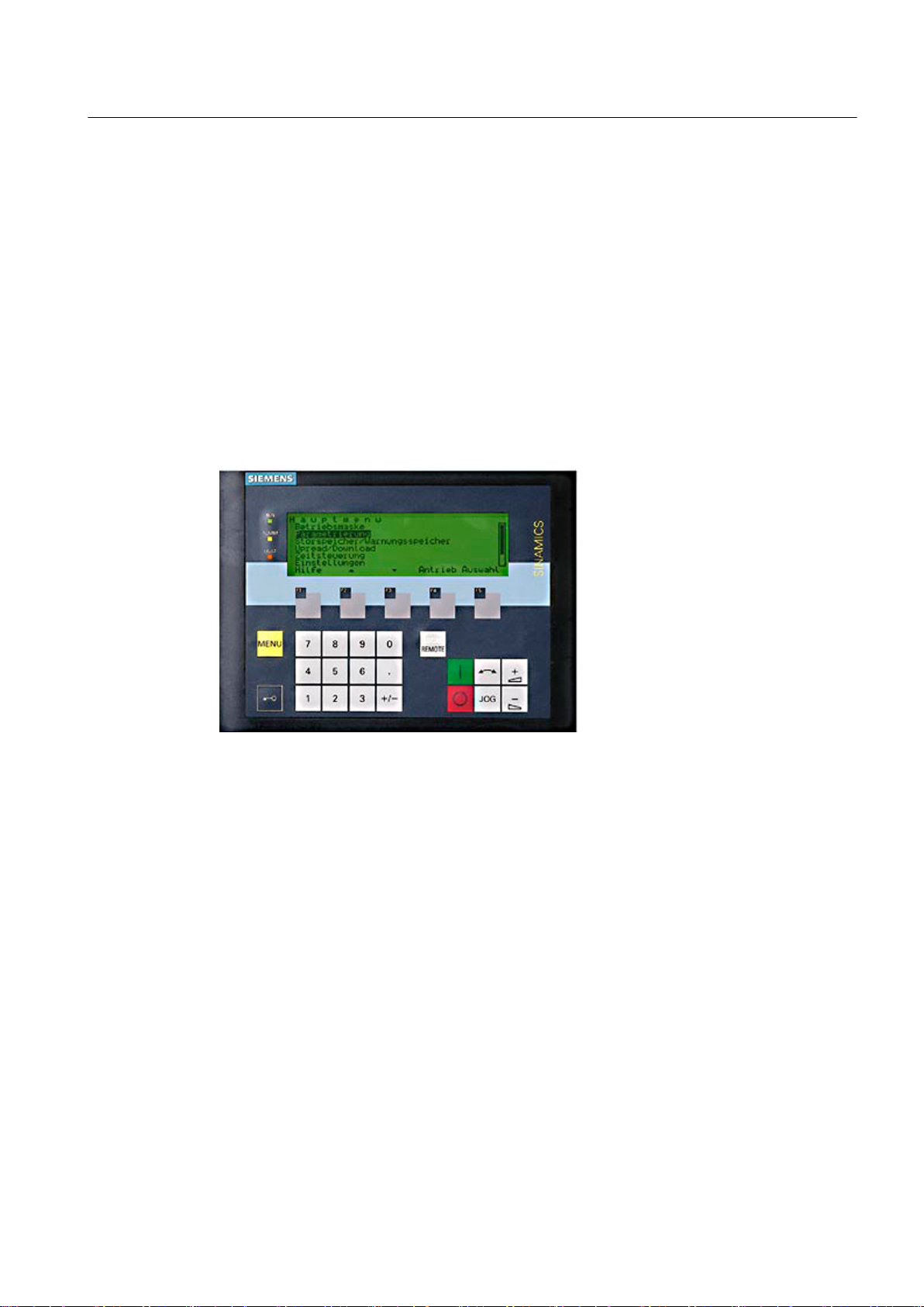
3.3.1 AOP30 operator panel
You can use the Advanced Operator Panel (AOP30) for operating, and diagnosing the drive.
The AOP30 communicates with the drive via a serial RS-232 interface with PPI protocol. The
interface is a point-to-point connection. The AOP30 has the master function in this
communication. The connected drive has the slave function.
Functions of the AOP30
Description
3.3 Components
Figure 3-1 AOP30 operator panel
The AOP30 has the following features and functions:
● Graphics-capable LCD with the following features
– Green backlighting for plain-text display
– Resolution of 240 x 64 pixels
– Quasi-analog bar-type display for process variables
● Keypad for operational control of a drive
● Numeric keypad for the numeric input of parameter values
● 4 LEDs for indicating the operating state of the drive unit:
– RUN: green
– ALARM: yellow
– FAULT: red
– LOCAL/REMOTE: green
● Help function describing causes of and remedies for faults and alarms
SINAMICS SM120 6SL38715
Operating Instructions 07/2015 29
0(18
/2&$/
5(027(
-2*
)
)
Description
3.3 Components
● Function keys for prompted navigation through the menus
● Realtime clock for the time stamping of faults and for setting up simple time controls
● LOCAL/REMOTE switchover for selecting the operating location
● Two-stage security concept to protect against unintentional or unauthorized changes to
settings.
● Time and date memory powered by internal battery backup
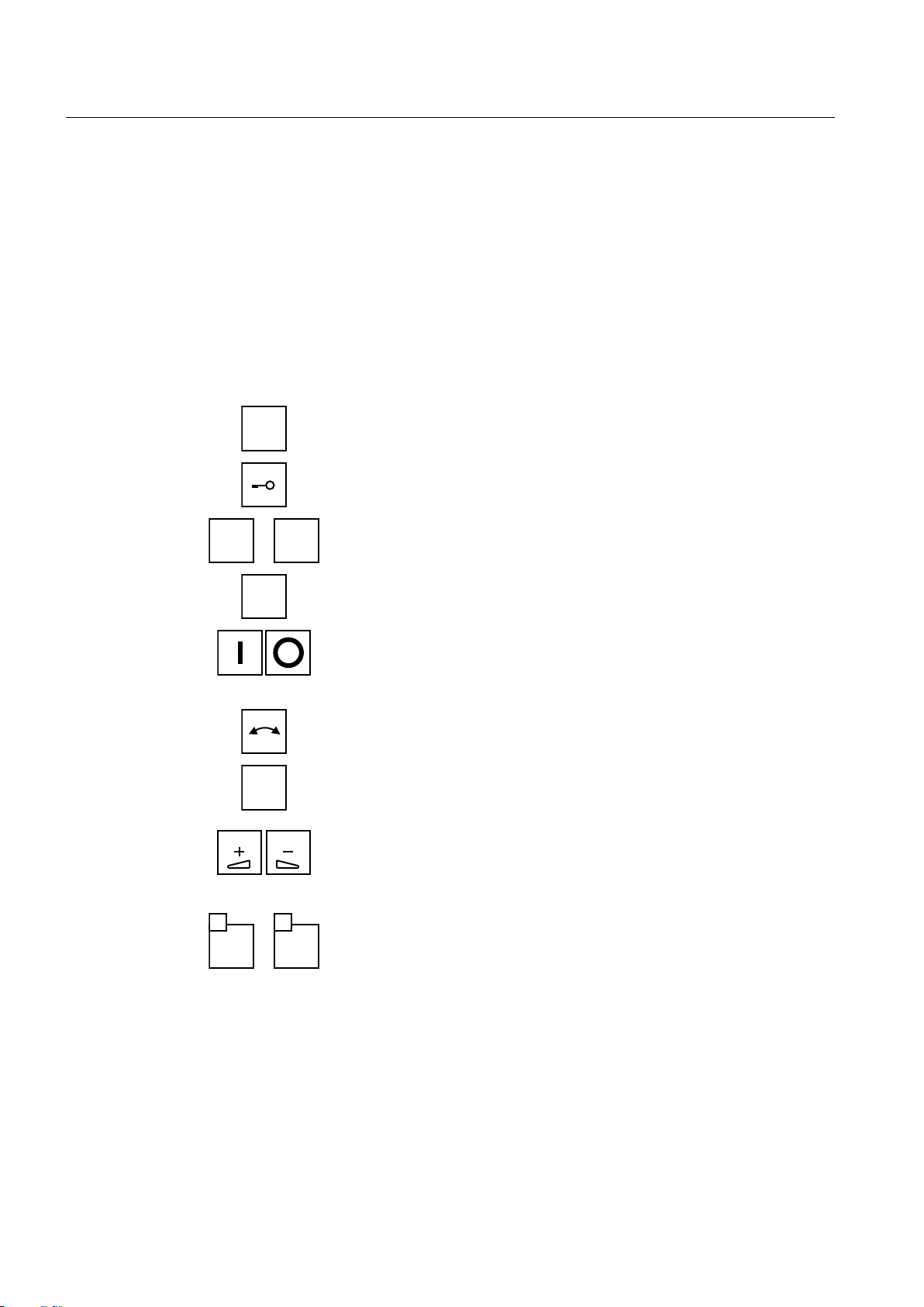
Functions of the control keys
Calls the main menu of the AOP30.
Calls the "inhibit functions" menu.
Numeric keys for direct entry of values.
Switches between remote and local mode. In local operation, the LED illu‐
minates.
On/off
If no operator inhibit is activated, then the "On" button in local operation is
always active. The "Off" button is only active in local operation, and in the
factory setting acts as "OFF1".
Counterclockwise-clockwise switchover
The button is only active in local mode.
JOG (Jogging)
The key is only in effect in local mode in "Ready to switch on" status (not
when "operating"). The system is accelerated to the setpoint speed.
Setpoint "increase" and setpoint "decrease".
You can enter the setpoint using these buttons. Alternatively, you can enter
the setpoint using the alphanumeric keys. Using the numeric keypad, any
speed ranging between the maximum and minimum speed can be entered.
Function keys.
These keys have different functions depending on the menu. The respec‐
tive function appears in plain text above the key.
3.3.2 Control Unit
The CU320-2 DP Control Unit is the central control module of the drive's open-loop and closedloop control system. The connections are wired internally to the customer terminal block.
SINAMICS SM120 6SL38715
30 Operating Instructions 07/2015
 Loading...