

Siemens SINAMICS SL150 6SL38655UM427AA02 Operating Instructions Manual

www.siemens.com/drives
This documentation pertains to
Operating Instructions
Installation Instructions
Medium-Voltage Drive
SINAMICS SL150
Type 6SL38655UM427AA02
EXAMPLE
Edition 10/2019

28.10.2019 15:07
V18.00

Medium-Voltage Drive
SINAMICS SL150
Type 6SL38655UM427AA02
This documentation pertains to
EXAMPLE
Introduction
1
Operating Instructions
Installation Instructions
Safety information
Description
Preparations for use
Mounting
Electrical connection
Commissioning
Operation
2
3
4
5
6
7
8
Maintenance
Spare parts
Disposal
Service & Support
Technical specifications and
drawings
9
10
11
A
B
Edition 10/2019

Legal information
Warning notice system
This manual contains notices you have to observe in order to ensure your personal safety, as well as to prevent
damage to property. The notices referring to your personal safety are highlighted in the manual by a safety alert
symbol, notices referring only to property damage have no safety alert symbol. These notices shown below are
graded according to the degree of danger.
DANGER
indicates that death or severe personal injury will result if proper precautions are not taken.
WARNING
indicates that death or severe personal injury may result if proper precautions are not taken.
CAUTION
indicates that minor personal injury can result if proper precautions are not taken.
NOTICE
indicates that property damage can result if proper precautions are not taken.
If more than one degree of danger is present, the warning notice representing the highest degree of danger will be
used. A notice warning of injury to persons with a safety alert symbol may also include a warning relating to property
damage.
Qualified Personnel
The product/system described in this documentation may be operated only by personnel qualified for the specific
task in accordance with the relevant documentation, in particular its warning notices and safety instructions. Qualified
personnel are those who, based on their training and experience, are capable of identifying risks and avoiding
potential hazards when working with these products/systems.
Proper use of Siemens products
Note the following:
WARNING
Siemens products may only be used for the applications described in the catalog and in the relevant technical
documentation. If products and components from other manufacturers are used, these must be recommended or
approved by Siemens. Proper transport, storage, installation, assembly, commissioning, operation and
maintenance are required to ensure that the products operate safely and without any problems. The permissible
ambient conditions must be complied with. The information in the relevant documentation must be observed.
Trademarks
All names identified by ® are registered trademarks of Siemens AG. The remaining trademarks in this publication
may be trademarks whose use by third parties for their own purposes could violate the rights of the owner.
Disclaimer of Liability
We have reviewed the contents of this publication to ensure consistency with the hardware and software described.
Since variance cannot be precluded entirely, we cannot guarantee full consistency. However, the information in this
publication is reviewed regularly and any necessary corrections are included in subsequent editions.
Siemens AG
Large Drives Applications
Vogelweiherstr. 1-15
90441 NÜRNBERG
GERMANY
Document order number: 0009993865-000010
Ⓟ 10/2019 Subject to change
Copyright © Siemens AG 2019.
All rights reserved

Table of contents
1 Introduction...................................................................................................................................................9
1.1 About these Operating Instructions..........................................................................................9
1.2 Text format features .................................................................................................................9
2 Safety information.......................................................................................................................................11
2.1 Warning symbol on the device ...............................................................................................11
2.2 Qualified personnel ................................................................................................................11
2.3 The 5 safety rules...................................................................................................................11
2.4 Safe handling .........................................................................................................................12
2.5 Electromagnetic fields in electrical power engineering installations ......................................14
2.6 Components that can be destroyed by electrostatic discharge (ESD)...................................15
2.7 Information for nominated persons in control of an electrical installation...............................16
2.7.1 Proper usage..........................................................................................................................16
2.7.2 Grounding concept.................................................................................................................18
2.7.3 Installation site safety.............................................................................................................18
2.7.4 Instructions for inverters with no grounding switch ................................................................19
2.7.5 Measures for operator protection in electromagnetic fields ...................................................19
2.8 Residual risks.........................................................................................................................19
2.9 Security information ...............................................................................................................21
3 Description..................................................................................................................................................23
3.1 Applications............................................................................................................................23
3.2 Safety concept .......................................................................................................................23
3.3 Power unit ..............................................................................................................................24
3.3.1 Product features.....................................................................................................................24
3.3.2 Power unit components..........................................................................................................25
3.3.2.1 Components of the converter module ....................................................................................25
3.3.2.2 Design of the thyristor modules..............................................................................................26
3.3.2.3 AVT combination module .......................................................................................................28
3.3.2.4 Power Stack Adapter .............................................................................................................28
3.3.2.5 Current transformer................................................................................................................29
3.3.2.6 Surge arresters ......................................................................................................................29
3.3.2.7 Overview of the additional components .................................................................................29
3.3.3 Principle of operation .............................................................................................................29
3.3.3.1 Thyristor electronics ...............................................................................................................30
3.3.3.2 Voltage actual value sensing .................................................................................................31
3.4 Closed-loop control ................................................................................................................31
3.4.1 Description of the components...............................................................................................31
3.4.1.1 DC/DC converter....................................................................................................................31
SINAMICS SL150 6SL38655UM427AA02
Operating Instructions Rev.201910281507 EXAMPLE 5

Table of contents
4 Preparations for use ...................................................................................................................................33
4.1 Requirements when mounting and installing the device ........................................................33
4.1.1 Requirements for installation location ....................................................................................33
4.1.2 Requirements placed on the levelness of the floor ................................................................33
4.2 Inspections when receiving the delivery.................................................................................34
4.2.1 Checking shock and tilt indicators..........................................................................................34
4.2.2 Checking the load handling attachments ...............................................................................35
4.3 Transportation ........................................................................................................................36
4.3.1 Transport markings ................................................................................................................36
4.3.2 Transport requirements..........................................................................................................36
4.3.3 Observe center of gravity.......................................................................................................37
4.3.4 Transport with a fork-lift truck.................................................................................................37
4.3.5 Transport with a crane ...........................................................................................................38
4.3.6 Using lifting rods.....................................................................................................................38
4.3.7 Transporting transportation units packed in boxes ................................................................40
4.4 Unpacking ..............................................................................................................................41
4.4.1 Removing the packaging........................................................................................................41
4.4.2 Removing load securing devices ...........................................................................................42
4.4.3 Lifting the cabinet off the transport pallet ...............................................................................42
4.4.4 Opening doors in preparation for use.....................................................................................43
4.4.5 Checking the shock and tilt indicators inside the cabinet.......................................................43
4.5 Storage...................................................................................................................................44
4.5.1 Emptying the drive .................................................................................................................44
4.5.2 Storing a device .....................................................................................................................44
5 Mounting.....................................................................................................................................................47
5.1 Safety instructions for installation...........................................................................................47
5.2 Torques ..................................................................................................................................48
6 Electrical connection...................................................................................................................................51
6.1 Safety instructions for electrical connection ...........................................................................51
6.2 Note regarding unshielded cables..........................................................................................53
6.3 Electromagnetic compatibility.................................................................................................53
6.4 Using the equipotential bonding strip and shield bus.............................................................56
6.5 Connecting the closed-loop control........................................................................................57
6.5.1 Connecting ground.................................................................................................................57
6.6 Interconnecting optional connections.....................................................................................57
6.7 Fastening the cable ducts with cable ties...............................................................................57
7 Commissioning ...........................................................................................................................................59
8 Operation....................................................................................................................................................61
8.1 Safety instructions for operation.............................................................................................61
8.2 Fault and system messages ..................................................................................................62
8.2.1 Diagnostics.............................................................................................................................62
8.2.1.1 Diagnostics via LEDs .............................................................................................................62
SINAMICS SL150 6SL38655UM427AA02
6 Operating Instructions Rev.201910281507 EXAMPLE

Table of contents
9 Maintenance ...............................................................................................................................................65
9.1 Safety instructions for maintenance .......................................................................................65
9.2 Grounding the system ............................................................................................................67
9.3 Preventive maintenance.........................................................................................................67
9.3.1 Visual inspections ..................................................................................................................68
9.3.1.1 Equipment for visual inspections............................................................................................68
9.3.1.2 Checking the isolating clearances..........................................................................................68
9.3.1.3 Checking hoisting solenoids and security bolts......................................................................68
9.3.1.4 Checking the plug connections. .............................................................................................69
9.3.1.5 Checking the cable and screw terminals................................................................................69
9.3.1.6 Checking the cooling circuit ...................................................................................................69
9.4 Maintenance...........................................................................................................................69
9.4.1 Replacing a fan ......................................................................................................................69
9.4.2 Replacing the back-up battery of the AOP30 operator panel ................................................70
9.5 Cleaning .................................................................................................................................71
9.5.1 Cleaning aluminum parts .......................................................................................................72
9.5.2 Cleaning the cooling unit filter................................................................................................72
9.6 Repairs...................................................................................................................................72
9.6.1 Replacing the snubber circuit resistor....................................................................................74
9.6.2 Replacing the snubber circuit capacitor .................................................................................75
9.6.3 Replacing the CompactFlash card.........................................................................................76
9.6.4 Replacing the thyristor electronics and thyristors...................................................................76
9.6.4.1 Check components of the thyristor assembly ........................................................................76
9.6.4.2 Replacing thyristor electronics ...............................................................................................77
9.6.4.3 Replacing a thyristor ..............................................................................................................81
9.6.4.4 Disconnecting the fiber-optic cables ......................................................................................83
9.6.5 Replacing components in the cooling circuit..........................................................................84
10 Spare parts .................................................................................................................................................87
11 Disposal......................................................................................................................................................89
11.1 Disposing of packaging material ............................................................................................89
11.2 Removing device components and old devices .....................................................................89
A Service & Support.......................................................................................................................................91
A.1 Siemens Industry Online Support ..........................................................................................91
A.2 SIOS App ...............................................................................................................................92
B Technical specifications and drawings .......................................................................................................93
B.1 Standards and regulations .....................................................................................................93
B.2 Environmental conditions .......................................................................................................94
Index...........................................................................................................................................................97
Tables
Table 3-1 Additional components for completion of the power module.......................................................29
SINAMICS SL150 6SL38655UM427AA02
Operating Instructions Rev.201910281507 EXAMPLE 7

Table of contents
Table 5-1 Tightening torque for screws.......................................................................................................48
Table 5-2 Tightening torques for screw terminals for copper cables without cable lug 1)...........................48
Table 8-1 LEDs of the Power Stack Adapters ............................................................................................62
Table 9-1 Technical specifications of the backup battery............................................................................70
Table 9-2 Torques of the capacitor connections .........................................................................................75
Table B-1 Standards and regulations ..........................................................................................................93
Table B-2 Climatic environmental conditions...............................................................................................94
Table B-3 Mechanical ambient conditions ...................................................................................................94
Table B-4 Other ambient conditions ............................................................................................................95
Figures
Figure 3-1 Schematic diagram: Components of the converter module ........................................................25
Figure 3-2 Example: Clamped thyristor assembly comprising 2 x 12 thyristors and 2 x 13 heat sinks ........26
Figure 3-3 Schematic diagram of the thyristor module cooling system ........................................................27
Figure 3-4 AVT combination module ............................................................................................................28
Figure 3-5 Example: Power Stack Adapter...................................................................................................28
Figure 3-6 Overview of the voltage sensing circuit.......................................................................................31
Figure 4-1 Example of attaching and displaying the shock and tilt indicators ..............................................35
Figure 4-2 Example illustration of centers of gravity.....................................................................................37
Figure 4-3 Lifting bar label............................................................................................................................39
Figure 4-4 Securing the lifting rods...............................................................................................................39
Figure 4-5 Transporting a transportation unit (still in packaging) with a crane .............................................41
Figure 4-6 Example: Cover screw for manual door interlocking...................................................................43
Figure 6-1 Shield connection using a clip.....................................................................................................55
Figure 6-2 Bridging shield gaps....................................................................................................................55
Figure 6-3 Equipotential bonding strip..........................................................................................................56
Figure 6-4 Grounding lug..............................................................................................................................57
Figure 6-5 Schematic diagram: Fastening the cable ties..............................................................................57
Figure 9-1 Replacing the backup battery......................................................................................................70
Figure 9-2 Replacing the snubber circuit resistor .........................................................................................74
Figure 9-3 Thyristor rack position .................................................................................................................77
Figure 9-4 Disengaging the interlocking on the thyristor electronics ............................................................79
Figure 9-5 Open-ended wrench in groove....................................................................................................82
Figure 9-6 Releasing a fiber-optic cable.......................................................................................................83
Figure 9-7 Replacing components in the cooling circuit ...............................................................................84
SINAMICS SL150 6SL38655UM427AA02
8 Operating Instructions Rev.201910281507 EXAMPLE

Introduction
1.1 About these Operating Instructions
These Operating Instructions describe the device and provide you with information about
handling it - from the initial shipment up to disposal. Keep these instructions for later use.
Read these Operating Instructions and comply with the information provided in them. In this
way you can ensure safe, problem-free operation and a long service life.
Safety information and handling-related warnings are provided in these Operating Instructions.
For your own safety, the safety of other persons and to avoid material damage, carefully follow
these instructions when carrying out any work.
If you have suggestions for improving the document, please contact our Service Center
(Page 91).
1.2 Text format features
1
Text format features
You can find the following text format features in these instructions:
1. Handling instructions are always formatted as a numbered list. Always perform the steps in
● Lists are formatted as bulleted lists.
Note
The note provides you with additional information about the product itself, handling the product
- and the relevant documentation.
the order given.
– Lists on the second level are hyphenated.
SINAMICS SL150 6SL38655UM427AA02
Operating Instructions Rev.201910281507 EXAMPLE 9

Introduction
1.2 Text format features
SINAMICS SL150 6SL38655UM427AA02
10 Operating Instructions Rev.201910281507 EXAMPLE
Safety information
In the individual chapters of this document, you will find safety instructions that must be obeyed
absolutely, for your own safety, to protect other people and to avoid damage to property.
Carefully comply with the following safety instructions when performing all of the activities.
2.1 Warning symbol on the device
Please observe the warning symbols attached to the device. The warning symbols have the
following meaning:
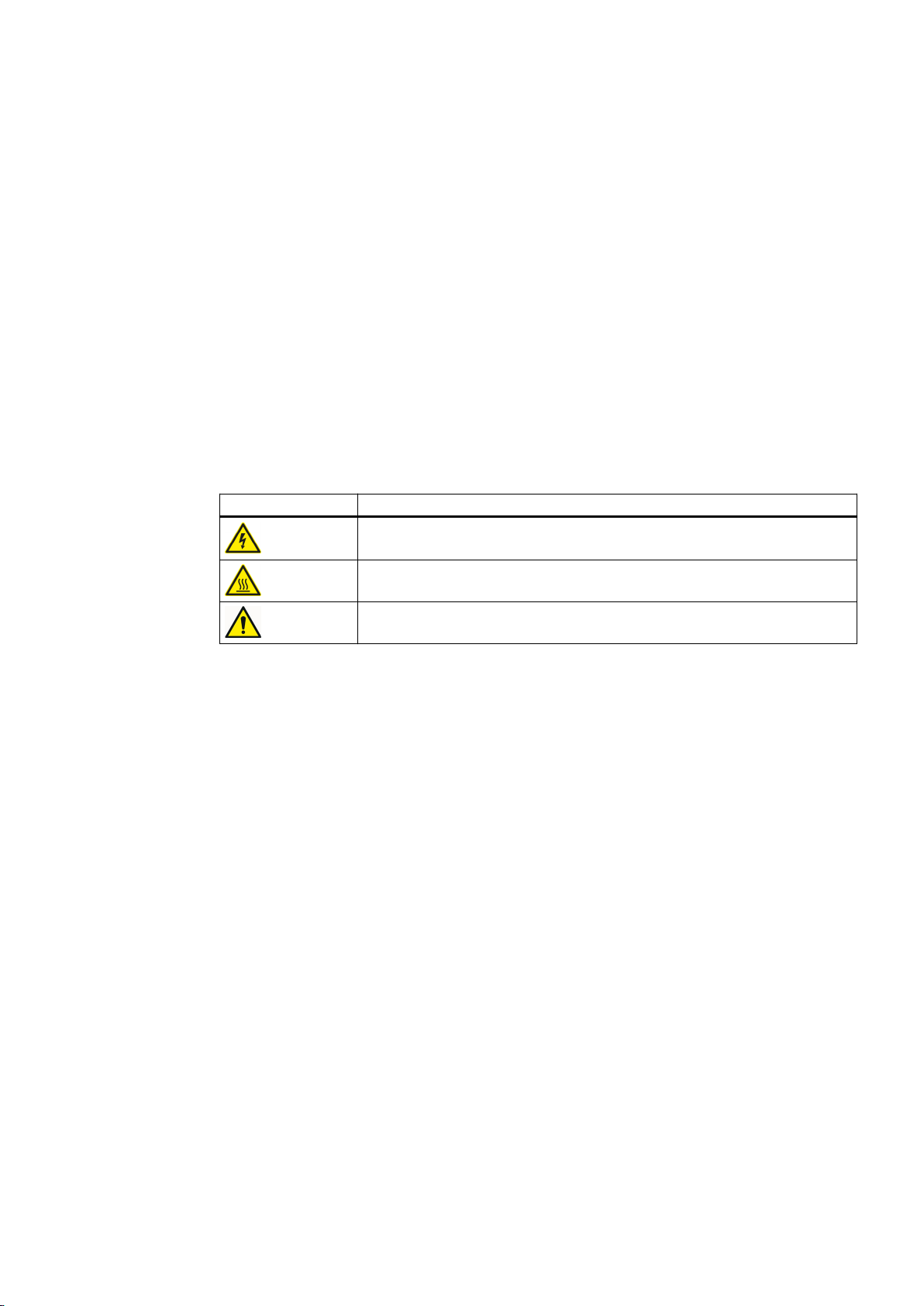
Warning symbol Meaning
Warning: Voltage
Warning: Hot surface
General warning symbol: Observe the explanations about the hazard on the
device labels.
2
For transportation, observe the "transportation markings (Page 36)" on the device packaging.
2.2 Qualified personnel
The product/system described in this documentation may only be operated by personnel
qualified for the specific task in accordance with the relevant documentation for the specific
task, in particular its warning notices and safety instructions. Because of their training and
experience, qualified personnel can recognize any risks involved with handling these products/
systems and avoid any possible dangers.
2.3 The 5 safety rules
For your own personal safety and to prevent material damage when carrying out any work,
always observe the safety-relevant instructions and the following five safety rules according to
EN 50110‑1 "Working in a voltage-free state". Apply the five safety rules in the sequence stated
before starting work.
5 safety rules
1. Disconnect the system.
Also disconnect the auxiliary circuits, for example, anti-condensation heating.
2. Secure against reconnection.
SINAMICS SL150 6SL38655UM427AA02
Operating Instructions Rev.201910281507 EXAMPLE 11

Safety information
2.4 Safe handling
3. Verify absence of operating voltage.
4. Ground and short-circuit.
5. Provide protection against adjacent live parts.
To energize the system, apply the measures in reverse order.
2.4 Safe handling
Danger as a result of high voltages from external supplies
Even if the circuit breaker is open, parts of the converter can be under voltage (live) as a result
of the auxiliary voltage at the premagnetization, precharging or demagnetization transformers.
This danger is not limited to the converter, but can also occur with components that are
electrically connected to the converter (e.g. circuit breakers or isolators). Touching live parts
can result in death, serious injury, and damage to property.
● Isolate all components that can feed voltage to the converter before commencing work.
Danger due to high voltage in operation
When operating this equipment very high voltages develop. Even after switching off the mains
voltage, or while the connected machine is still turning, high voltages can remain for a
prolonged length of time. High voltages can cause death or serious injury if the safety rules are
not observed or if the equipment is handled incorrectly.
● Operate the device properly.
● Always follow the "The five safety rules (Page 11)" when performing any work.
● Service and maintain the device regularly and correctly.
Danger as a result of induced voltage
Rotating machinery can induce dangerous high voltages and synchronous motors that are not
de-excited immediately can also pose a hazard. If the connection to the motor is not isolated or
grounded, these voltages can also remain. Touching live parts can result in death or serious
injury.
● Before opening the doors, wait until the connected machine has come to a standstill.
Danger due to high auxiliary voltages
High auxiliary voltages are still present even after shutdown. Touching live parts can result in
death or serious injury.
● Observe the five safety rules when performing any work.
SINAMICS SL150 6SL38655UM427AA02
12 Operating Instructions Rev.201910281507 EXAMPLE

Danger due to hazardous arcing
Hazards caused by arcing can occur as result of the following factors, for example:
● The input currents are exceeded.
● Incorrectly dimensioned circuit breaker or transformers.
● Incorrectly connected cables or cables that have not been connected.
● Contamination and dirt.
● Tools that have been forgotten, e.g. when mounting and installing the equipment.
Arcing can result in death, serious injury or material damage.
● Make sure that the system is properly dimensioned and that the power cables are correctly
connected. The maximum permissible input currents are listed in the "Technical
specifications".
● Remove contamination and dirt.
● After installation and mounting, carefully check that no objects have been left in the device.
Danger due to live stationary parts, moving or rotating parts
Safety information
2.4 Safe handling
Contact with the parts mentioned can result in death, serious physical injury or damage to
property.
● Observe the instructions regarding installation and operation.
● Always take protective measures before touching any components.
● Do not remove any covers.
Risk of burns due to hot component surfaces
Certain components (e.g. heat sinks and reactors) can become very hot during operation.
These components can remain hot for a long time after operation. Contact can result in serious
injury, such as skin burns.
● After the device has been shut down, do not touch any hot components.
Risk of injury at places that are difficult to access
If you do not use appropriate protective equipment when working in places that are difficult to
access you are at risk of injury. For example, sharp edges and splinters can cause injuries to
the head and skin. If you carry out work in the upper section using unsuitable ladders or similar,
you can fall and injure yourself.
● Use appropriate protective equipment, especially a hard hat and gloves.
● Use suitable steps or ladders when working in the upper area.
SINAMICS SL150 6SL38655UM427AA02
Operating Instructions Rev.201910281507 EXAMPLE 13

Safety information
2.5 Electromagnetic fields in electrical power engineering installations
Injury caused by deionized water
Deionized water is harmful to eyes and skin and can damage surfaces.
● Therefore, use appropriate protective clothing for all work on the converter. However, if your
eyes or skin do come into contact with deionized water, rinse the affected area thoroughly
with tap water as soon as possible.
● If deionized water leaks out, eliminate the source of the problem and remove the liquid from
the surfaces affected.
Shutdown as a result of an incorrect residual current monitoring device
If you use a residual current monitoring device (RCD), it is possible that the residual current
monitoring device will trip in error (nuisance trip). The converter may be switched off as a result
of the protection device tripping in error.
● To minimize the risk of faulty trips, use a type-B RCD.
2.5 Electromagnetic fields in electrical power engineering installations
Electromagnetic fields are generated during operation of electrical power engineering
installations. Electromagnetic fields can interfere with electronic devices, These devices can
malfunction if electromagnetic fields are present.
WARNING
Interference with pacemakers
The functioning of cardiac pacemakers could be impaired by electromagnetic fields. Death or
serious physical injury can result.
● As a consequence, it is not permissible for people with pacemakers to stand close to the
device.
NOTICE
Data loss
Electromagnetic fields can cause data loss to magnetic or electronic data storage media.
● Therefore, do not carry magnetic or electronic data storage media with you.
Nominated persons in control of electrical installations can find further information on
electromagnetic fields under "Information for persons responsible for plants and systems."
SINAMICS SL150 6SL38655UM427AA02
14 Operating Instructions Rev.201910281507 EXAMPLE

Safety information
2.6 Components that can be destroyed by electrostatic discharge (ESD)
2.6 Components that can be destroyed by electrostatic discharge (ESD)
ESD guidelines
NOTICE
Electrostatic discharge
Electronic components can be destroyed in the event of improper handling, transport, storage,
and shipping.
Pack the electronic components in appropriate ESD packaging; e.g. ESD foam, ESD
packaging bags and ESD transport containers.
To protect your equipment against damage, follow the instructions given below.
● Avoid physical contact with electronic components. If it is essential that you perform work on
these components, you must wear one of the following pieces of protective gear:
– Grounded ESD wrist strap
– ESD shoes or ESD shoe grounding strips if there is also an ESD floor.
● Do not place electronic components close to data terminals, monitors or televisions.
Maintain a minimum clearance to the screen (> 10 cm).
● Electronic components should not be brought into contact with electrically insulating
materials such as plastic foil, plastic parts, insulating table supports or clothing made of
synthetic fibers.
● Bring components into contact only with ESD-compliant materials, e.g. ESD tables, ESD
surfaces, ESD packaging.
● Only carry out measurements on the components if one of the following conditions is met:
– The measuring device is grounded with a protective conductor, for example.
– The measuring head of a floating measuring device has been discharged directly before
the measurement.
The necessary ESD protective measures for the entire working range for electrostatically
sensitive devices are illustrated once again in the following drawings.
Precise instructions for ESD protective measures are specified in the standard
DIN EN 61340‑5‑1.
SINAMICS SL150 6SL38655UM427AA02
Operating Instructions Rev.201910281507 EXAMPLE 15

Safety information
2.7 Information for nominated persons in control of an electrical installation
① Sitting a Conductive floor cover‐
1)
ing
d ESD clothing
② Standing b ESD furniture e ESD wrist strap
③ Standing/sitting c Wearing of ESD shoes or
ESD shoe grounding
2)
strips
1)
Only effective in conjunction with ESD shoes or ESD shoe grounding strips
2)
Only effective in conjunction with conductive floor covering
f Cabinet ground connection
2.7 Information for nominated persons in control of an electrical
installation
2.7.1 Proper usage
These devices are intended to be permanently installed in closed and dry rooms with a clean
atmosphere. You can find the ambient and operating temperatures to be adhered to in the
technical data. If the described environmental conditions are not observed, warranty claims
and other claims may be rejected.
Explosions
If you operate the device in a hazardous zone, explosions can occur which can cause death,
serious injuries or material damage.
● Never operate the device in an explosive atmosphere (hazardous zone).
Non-observance of proper usage
Improper use of the devices described can result in death, severe injury or material damage.
● Please observe all instructions for proper use.
SINAMICS SL150 6SL38655UM427AA02
16 Operating Instructions Rev.201910281507 EXAMPLE

Safety information
2.7 Information for nominated persons in control of an electrical installation
The nominated person in control of an electrical installation must ensure that the following
points are observed:
● Follow the local and industry-specific safety and setup regulations. Observe the
requirements in the guidelines specified in the "Standards and regulations" section of the
"Technical data and drawings." Ensure that the specific safety and construction regulations
and the regulations for using personal protective equipment are observed during all work.
● The operating instructions and the complete product documentation are always available
when carrying out any work.
● The technical data as well as the specifications relating to the permissible installation,
connection, ambient and operating conditions are taken into account at all times.
● Only qualified personnel or personnel supervised by responsible, skilled specialists are
allowed to carry out basic planning and all work on the device.
● During shipping, specific transport conditions are adhered to.
● Assembly is performed according to assembly instructions. Separate cabinet units are
connected properly (cables and busbars).
● All instructions for EMC-compatible installation, cabling, shielding, grounding, and for
adequate auxiliary power supply are to be observed.
See also
● Commissioning is only to be performed by qualified personnel trained for that purpose in
accordance with the commissioning instructions.
● System configuration is carried out by an experienced system integrator. Additional system
components - such as circuit-breaker, transformer, cables and motor - are coordinated and
harmonized with one another for converter operation.
● The device is only operated in conjunction with the engineered components.
● Different operating modes, overloads, load cycles, and differing environmental conditions
are permitted only after special arrangement with the manufacturer.
Make use of the support and services offered by the relevant service center for planning,
installation, commissioning, and servicing work. You can find the relevant contact person under
"Service & Support (Page 91)".
Standards and regulations (Page 93)
SINAMICS SL150 6SL38655UM427AA02
Operating Instructions Rev.201910281507 EXAMPLE 17

Safety information
2.7 Information for nominated persons in control of an electrical installation
2.7.2 Grounding concept
Draw-up a grounding concept and integrate the device into this concept. The grounding
concept must take into consideration national provisions and system specifics. Ensure that the
following criteria are fulfilled:
● At the installation site, the various subunits must be screwed together to establish a good
electrical connection between them.
● If shield busbars are provided, these must be connected together.
● The protective grounding conductor must be connected to the system the grounding point.
Select the highest cross-section of the protective grounding conductor from one of the
following variants:
– According to local wiring regulations
– Calculated according to IEC 60364-5-54, 543.1
– Half a phase conductor cross-section
2.7.3 Installation site safety
Danger due to an unsecured installation location
This device is used in industrial power installations. Improper use, incorrect operation,
insufficient maintenance, and access by unauthorized persons can lead to accidents. The
results can be death, serious bodily injury or damage to property.
● Install the device in electrical rooms where only qualified personnel have access. If this is
not possible, then ensure that a barrier prevents uncontrolled access. Use safety fences and
appropriate signs, for example, to prevent unauthorized entry to the zone that has been
fenced off.
● Place notices that indicate that only trained personnel are allowed to operate and carry out
maintenance and repair work.
● To comply with safety regulations, equip plants and systems with additional monitoring and
protective devices. Follow technical equipment legislation and accident prevention
regulations.
Note
The converter will be supplied on request without an electromechanical door interlocking
system if space is restricted. In this instance, the customer must provide an access interlock
system compliant with IEC 61800-5 /-1.
SINAMICS SL150 6SL38655UM427AA02
18 Operating Instructions Rev.201910281507 EXAMPLE

2.7.4 Instructions for inverters with no grounding switch
Note
The drive does not have a grounding breaker at the input/output. The system operator must,
therefore, ensure that there is sufficient grounding.
2.7.5 Measures for operator protection in electromagnetic fields
The plant operator is responsible for taking the following appropriate measures (labels and
hazard warnings) to adequately protect operating personnel against any possible risk.
● Observe the relevant nationally applicable health and safety regulations or the applicable
national regulations in the country of installation. In Germany, "electromagnetic fields" are
subject to regulations BGV B11 and BGR B11 stipulated by the German statutory industrial
accident insurance institution.
● Display adequate hazard warning notices on the installation.
Safety information
2.8 Residual risks
● Place barriers around hazardous areas.
● Take measures, e.g. using shields, to reduce electromagnetic fields at their source.
● Make sure that personnel are wearing the appropriate protective gear.
2.8 Residual risks
According to the EU machinery directive, machine manufacturers / plant operators must
conduct a risk assessment of their machine. Plant operators must conduct a risk assessment
of their plant. In particular, pay attention to Annex 1 "General Principles" of the EU machinery
directive.
SINAMICS SL150 6SL38655UM427AA02
Operating Instructions Rev.201910281507 EXAMPLE 19

Safety information
2.8 Residual risks
Pay attention to the following residual risks:
● Unintentional movements of driven machine parts
Unintentional movements of driven machine parts can occur during commissioning,
operation, maintenance, and repair, e.g. from the following causes:
– Hardware defects and/or software errors in the sensors, controllers, actuators, and
connection technology
– Response times of the controller and drive
– Operating and/or environmental conditions outside of the specification
– Condensation/conductive contamination
– Parameterization, programming, cabling, and installation errors
– Use of radio devices/cell phones in the immediate vicinity of the controller
– External influences/damage
● High temperatures and emissions
A fault can occur as a result of the following, for example:
– Component malfunctions
– Software errors
– Operating and/or environmental conditions outside of the specification
– External influences/damage
For instance, a fault can have the following effects:
– Extraordinarily high temperatures, including open fires as a result of the fault
– Emissions of light, noise, particles or gases
Devices with "Open Type/IP20 degree of protection" must be installed in an electrical room
or a comparable environment.
● Hazardous shock voltages
Hazardous shock voltages can result from the following causes, for example:
– Component malfunctions
– Induction of voltages in moving motors
– Operating and/or environmental conditions outside of the specification
– Condensation/conductive contamination
– External influences/damage
● The release of substances and emissions that are harmful to the environment
Improper operation or the improper disposal of components can harm the environment.
SINAMICS SL150 6SL38655UM427AA02
20 Operating Instructions Rev.201910281507 EXAMPLE

Safety information
2.9 Security information
● Damage from pressure build-up during electric arcs in the event of a fault
If the building has not been designed correctly in terms of how it has been dimensioned,
damage can result from the pressure that can possibly build up inside.
● Dangerous electric arcs during internal faults
The devices have been designed according to the relevant IEC standards, and tested in line
with strict type-testing procedures. They were developed and manufactured so that there is
a very low probability of internal faults occurring. However, internal faults cannot be
completely ruled out.
WARNING
Dangerous electric arcs during internal faults
Defects such as damage to components, overvoltages, or loose parts, as well as exceptional
operating statuses, can cause a failure within the enclosure. This can result in an internal
electric arc. If an electric arc occurs and people are nearby, this could lead to death, serious
physical injury, and damage to property.
● Ensure that only qualified personnel perform any work that is required.
● Observe the safety and operating instructions in this documentation and labels attached to
the device for any work that is performed.
2.9 Security information
Siemens provides products and solutions with industrial security functions that support the
secure operation of plants, systems, machines, and networks.
In order to protect plants, systems, machines and networks against cyber threats, it is
necessary to implement – and continuously maintain – a holistic, state-of-the-art industrial
security concept. Siemens’ products and solutions only form one element of such a concept.
Customer is responsible to prevent unauthorized access to its plants, systems, machines and
networks. Systems, machines and components should only be connected to the enterprise
network or the internet if and to the extent necessary and with appropriate security measures
(e.g. use of firewalls and network segmentation) in place.
Additionally, Siemens’ guidance on appropriate security measures should be taken into
account. You can find more information about industrial security by visiting:
https://www.siemens.com/industrialsecurity.
Siemens’ products and solutions undergo continuous development to make them more secure.
Siemens strongly recommends you apply product updates as soon as available and always
use the latest product versions. Use of product versions that are no longer supported, and
failure to apply latest updates may increase customer’s exposure to cyber threats.
To stay informed about product updates, subscribe to the Siemens Industrial Security RSS
Feed under
https://www.siemens.com/industrialsecurity.
Additional notes for this product are provided in the Internet and on the CD provided with the
device.
SINAMICS SL150 6SL38655UM427AA02
Operating Instructions Rev.201910281507 EXAMPLE 21

Safety information
2.9 Security information
"SINAMICS Industrial Security" Manual
Notes relating to Industrial Security are provided here (
support.industry.siemens.com/cs/ww/de/view/109751848/en).
https://
SINAMICS SL150 6SL38655UM427AA02
22 Operating Instructions Rev.201910281507 EXAMPLE

Description
3.1 Applications
The water-cooled cycloconverters for tube mill drives are used for slow speed drives with a high
power rating and the highest torques. For instance, these conditions prevail in the cement and
ore industry.
The cycloconverters are based on water-cooled thyristor stack technology. The converter is
suitable for four-quadrant operation without any additional equipment. This means that driving
and braking are possible in both directions of rotation.
The main components are:
● SINAMICS closed-loop control with CU and SIMOTION module
● Power module in degree of protection IP00
Depending on the circuit, the power module consists of three (12-pulse) or six (2x6-pulse)
open, water-cooled modules in a fuseless arrangement. Each group of three modules is
assembled as a "stack".
● Additional components
Every converter is assigned a package with additional components. The additional
components comprise AVT combi, voltage sensing, current sensing and overvoltage
limiting. The additional components are required to assemble a complete device.
3
Note
Auxiliary plant equipment
All auxiliary equipment necessary for operation, control and monitoring of the converter
must be specified and incorporated by the system integrator. The equipment is not included
in the scope of delivery.
3.2 Safety concept
DANGER
Insufficient grounding
High voltages can still be present even after shutdown. If live parts are touched, this can result
in death or severe injury.
A grounding switch is not installed. The system operator must, therefore, ensure that there is
sufficient grounding.
Ensure sufficient grounding during work on the power unit. Further information on grounding
can be found under "Safety information for maintenance and repairs".
SINAMICS SL150 6SL38655UM427AA02
Operating Instructions Rev.201910281507 EXAMPLE 23

Description
3.3 Power unit
3.3 Power unit
3.3.1 Product features
The water-cooled thyristor module is an electrical subcomponent that cannot be operated by
itself. You must use the water-cooled thyristor module in conjunction with additional
components to create an operational device.
The ultimate design can be varied depending on the required use:
● Use of different semiconductors from 3" to 4"
– Type T2351N52 (3"); T3441N52 (4") EUPEC or equivalent type
● Integration of two reversible converter bridges in series connection with number of thyristors
in series R=1
– 2×(B6C)A(B6C); 12-pulse output voltage
● One reversible converter bridge with number of thyristors in series R = 2
– 1×(B6C)A(B6C); 6-pulse output voltage
The thyristors are controlled optoelectronically via plastic fiber-optic conductors. The thyristors
are fired via the thyristor electronics.
Structurally the two stacks are installed in parallel in a "clamped assembly". The "open"
modules, degree of protection IP00, stand on insulators and are suppored by welded aluminum
sections.
The modules have a simple mechanical design with relatively few components. This
guarantees a correspondingly high MTBF (mean time between failures) and high reliability.
SINAMICS SL150 6SL38655UM427AA02
24 Operating Instructions Rev.201910281507 EXAMPLE
3.3.2 Power unit components
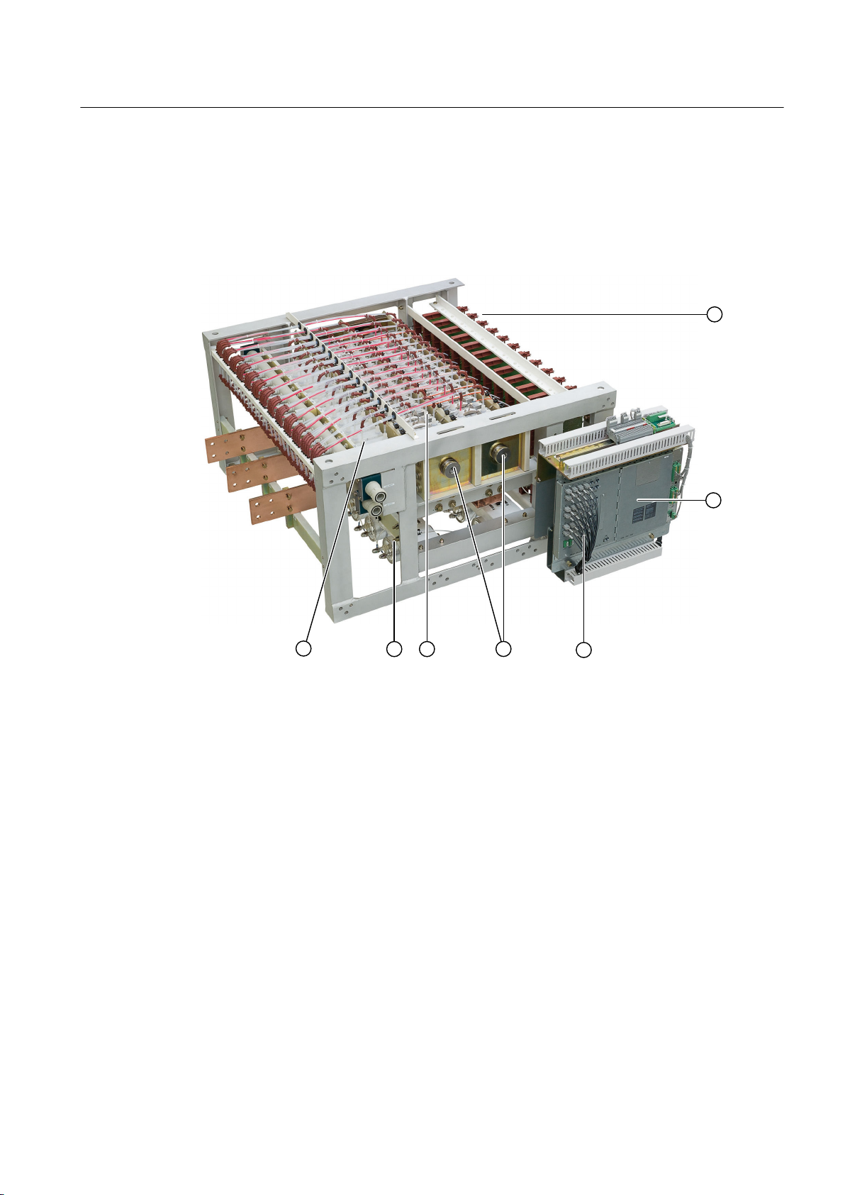
3.3.2.1 Components of the converter module
The converter module consists of the following components:
Description
3.3 Power unit
① Two mounting tiers for the thyristor electronic modules
② Power Stack Adapter (PSA)
③ Firing and checkback signals via opto-cables
④ Two clamped thyristor stacks, each with 12 thyristors
⑤ 2 x 13 water-cooled heat sinks each
⑥ Suppressor capacitors
⑦ Water-cooled snubber resistors
Figure 3-1 Schematic diagram: Components of the converter module
A module tower comprises three modules placed one on top of the other.
SINAMICS SL150 6SL38655UM427AA02
Operating Instructions Rev.201910281507 EXAMPLE 25
9
9
9
9
9
9
9
9
9
9
9
9
9
9
9
9
9
9
9
9
9
9
9
9
-
-
Description
3.3 Power unit
3.3.2.2 Design of the thyristor modules
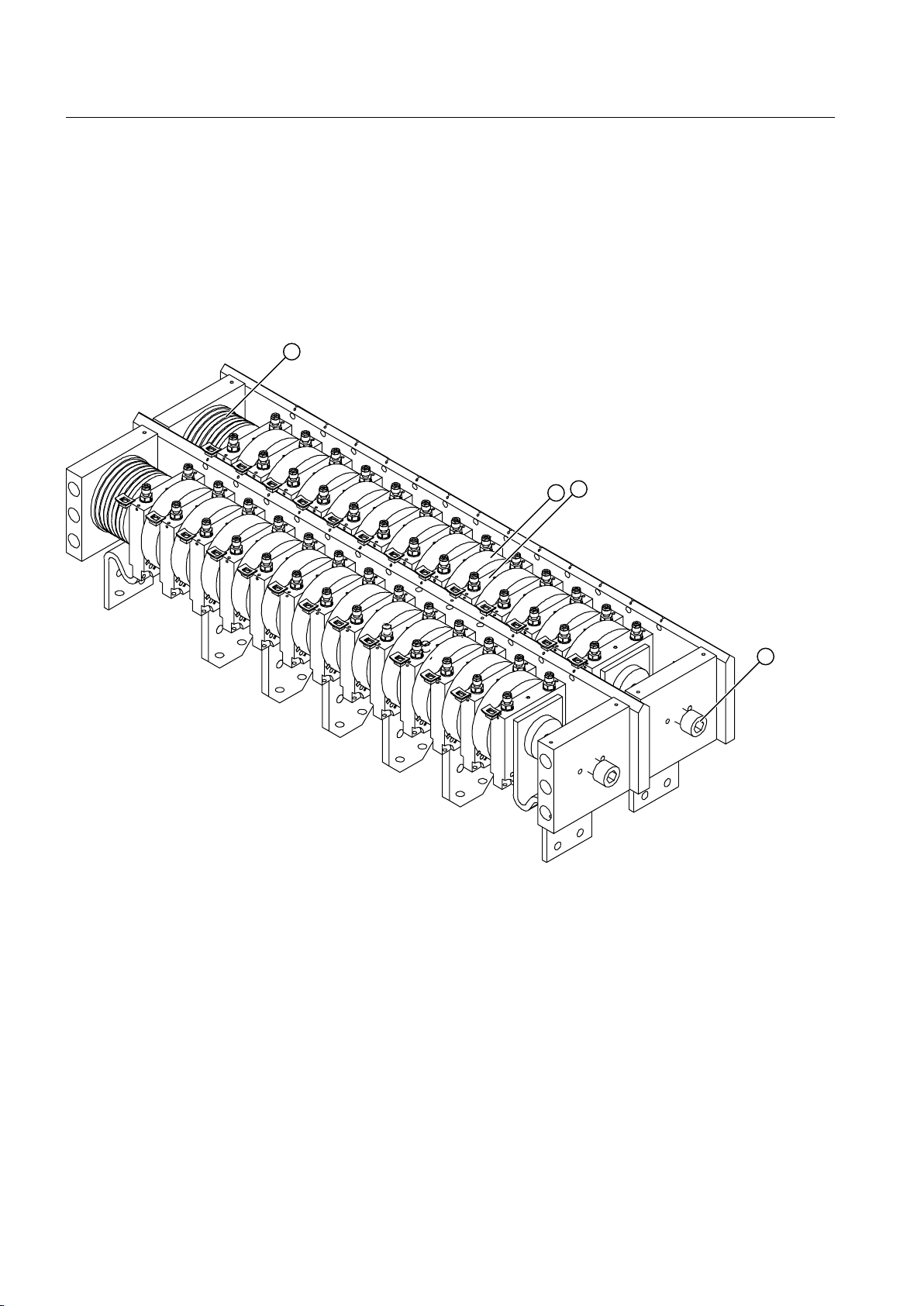
Clamped thyristor stack for number of thyristors connected in series 1 and 2
A thyristor module consists of two clamped thyristor stacks. A clamped thyristor assembly
comprises 12 thyristors in "flatpacks" and 13 heat sinks.
① Set of springs
② Thyristor
③ Heat sink
④ Clamping bolt
Figure 3-2 Example: Clamped thyristor assembly comprising 2 x 12 thyristors and 2 x 13 heat sinks
The clamped thyristor assembly is pressed together by a set of springs with a clamping screw
in such a way as to achieve the required contact force.
The purpose of the heat sinks is to dissipate heat losses.
SINAMICS SL150 6SL38655UM427AA02
26 Operating Instructions Rev.201910281507 EXAMPLE
RC circuit
Each anti-parallel pair of thyristors is damped by means of a water-cooled resistor and a
capacitor.
The RC circuit has the following tasks:
● It divides the line voltage evenly in the case of number of thyristors in series 2.
● It limits the rate of voltage rise and voltage overshoot when the thyristors are turned off.
Thyristor electronics
The thyristors are fired by indirect light pulse firing with the TAS 21 modules.
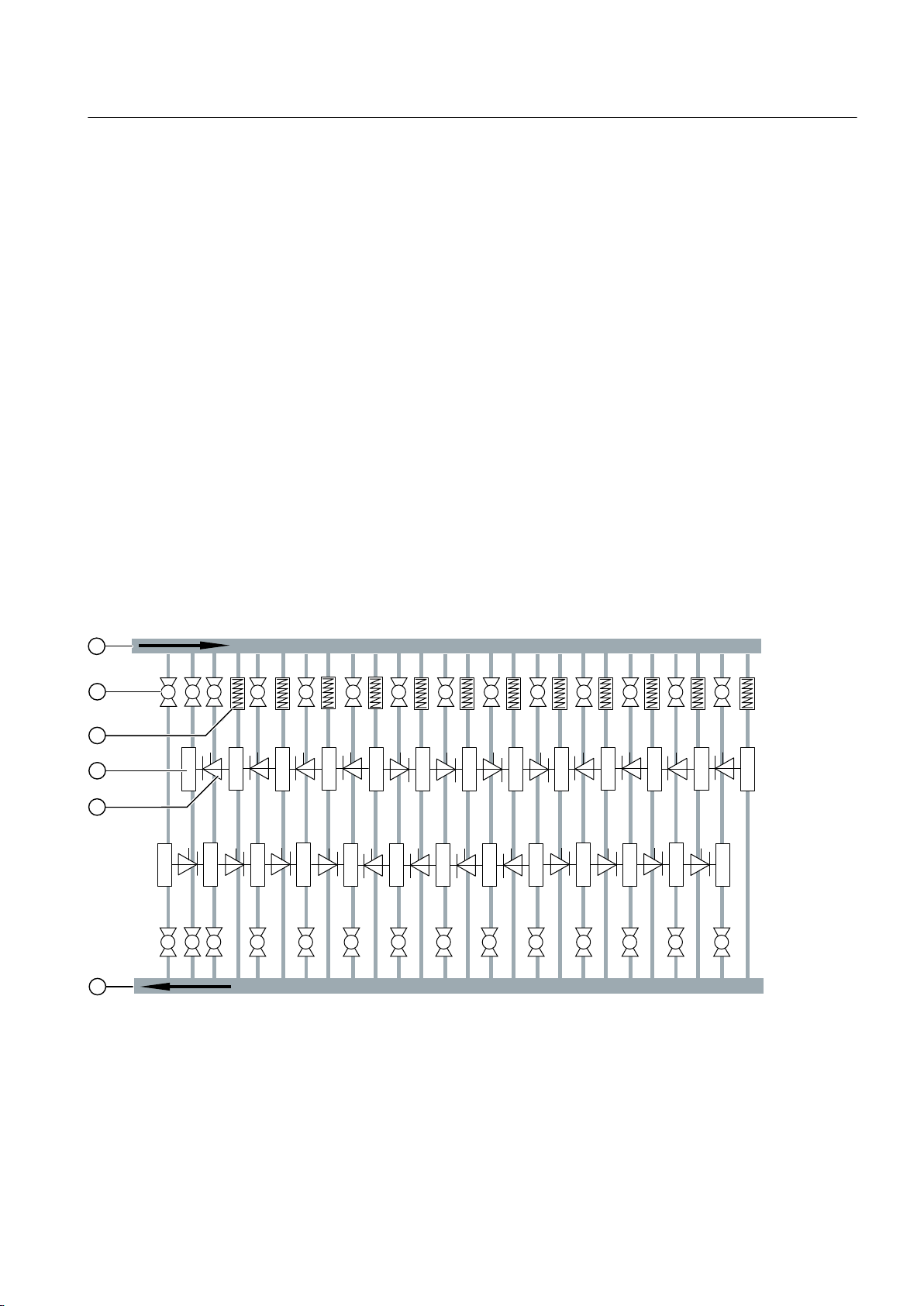
Cooling
The thyristor module is water-cooled. In the inner converter circuit, the deonized water that
warms up absorbs the heat to be dissipated from the converter power unit. The deionized water
is cooled in the cooling unit. The deionized water is then fed back to the converter using pumps.
The internal deionized water circuit is filled with deionized water. The cooling water conductivity
is approximately 0.2 µS / cm to 0.6 µS / cm.
Description
3.3 Power unit
The thyristor modules with their water-cooled suppressor resistors and heat sinks are
connected to the deionized water circuit.
① Water inlet
② Water flow restrictor
③ Suppressor resistor
④ Heat sink
⑤ Thyristor
⑥ Water drain
SINAMICS SL150 6SL38655UM427AA02
Operating Instructions Rev.201910281507 EXAMPLE 27
Description
3.3 Power unit
Figure 3-3 Schematic diagram of the thyristor module cooling system
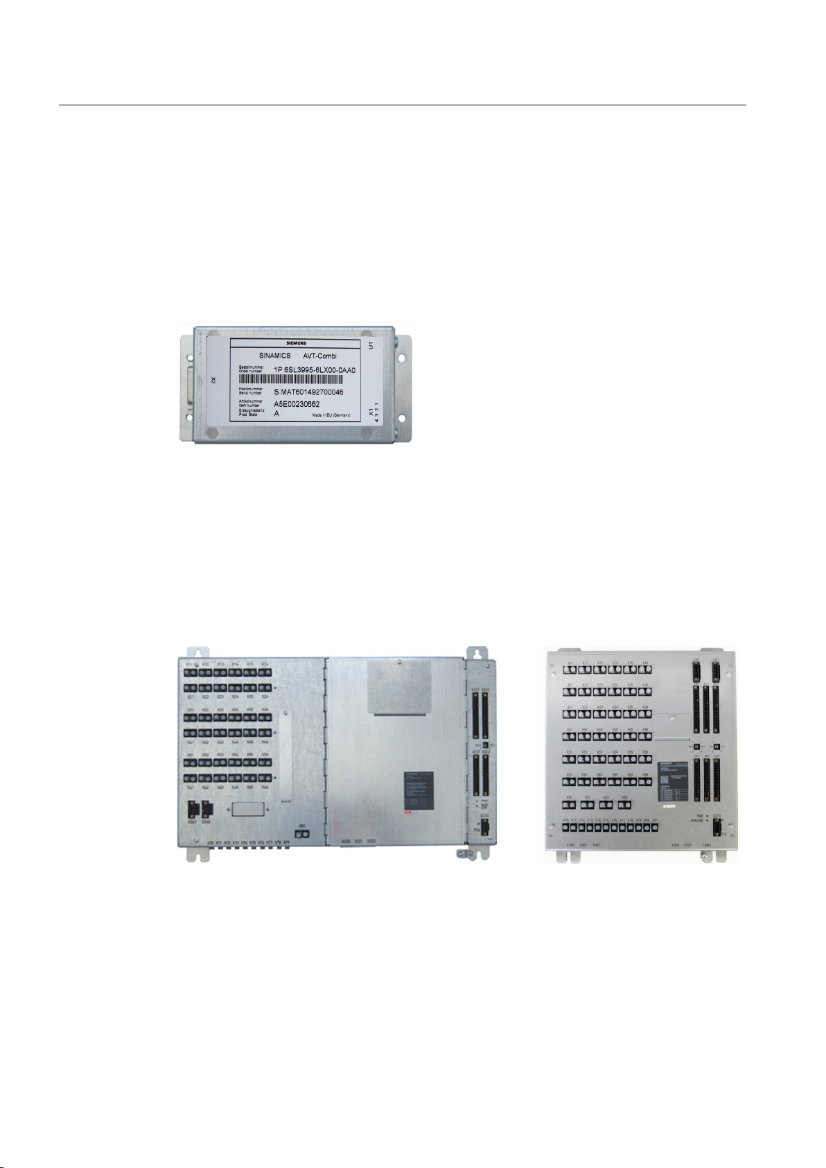
3.3.2.3 AVT combination module
The AVT combination module (Actual Value Transmission) processes signals for sensing the
actual current and voltage values. The AVT combination module converts analog signals into
digital signals. Then the module transfers the signals to the Power Stack Adapter (PSA). The
signals are transferred to the PSA via fiber-optic cables.
Figure 3-4 AVT combination module
See also
Voltage actual value sensing (Page 31)
3.3.2.4 Power Stack Adapter
Figure 3-5 Example: Power Stack Adapter
The power stack adapter (PSA) acts as an interface between the power unit and the open-loop/
closed-loop controller. The Power Stack Adapter is also where the power unit is electrically
isolated from the open-loop/closed-loop controller. The DRIVE-CLiQ serial communication
interface ensures the exchange of data between the Power Stack Adapter and Control Unit
(CU).
In the Power Stack Adapter, the switching information predefined by the Control Unit is
translated into firing pulses (long pulses). The firing pulses are converted to optical signals and
SINAMICS SL150 6SL38655UM427AA02
28 Operating Instructions Rev.201910281507 EXAMPLE

sent to the thyristor electronics via fiber-optic cables. This initiates firing readiness in the
thyristor electronics and activates a monitoring and interlocking logic circuit. The thyristor
electronics then determine the operating status of the thyristor and relays it to the Power Stack
Adapter via the checkback fiber-optic cable. The control commands and checkback signals
correlate with each other. Any disruption to this relationship, for example an open circuit in an
FO conductor or a failed thyristor, is relayed to the open-loop/closed-loop control system as an
error message.
3.3.2.5 Current transformer
Current transformers are used to measure current. The analog output signals from the current
transformer are post-processed by the AVT combination module and sent via the fiber-optic
cable to the power stack adapter. The primary circuit is separate from the secondary circuit.
3.3.2.6 Surge arresters
Overvoltages can occur when inductive loads are switched, for example, in the case of
transformer disconnections at no load. These overvoltages can pose a danger to the converter.
For indoor systems, surge arresters without spark gap are connected in a star configuration
between the phases to limit the overvoltages.
Description
3.3 Power unit
3.3.2.7 Overview of the additional components
Table 3-1 Additional components for completion of the power module
Order number Description Quantity installed in the converter (not included in the scope of
delivery)
3EK7060 6 kV surge arrester, 10 kA 18
A5E00715597 Current transformer 3 kA; 0.1 A / 5 A 18
322776 Varistor for the transformer 36
A5E02425179 UM measurement 3
A5E00230662 AVT combination module
6SL3995-6LX00-0AA0
Set of installation materials 1
18
3.3.3 Principle of operation
The maximum frequency (which is determined by the operating principle of the direct converter)
is approx. 40 % – 44 % of the line frequency. Thus with 4-pole motors on a 50 Hz supply, the
maximum achievable rotational speed is approx. 660 rpm. If the machines are operated over
a wide constant power range, the rated speed is normally significantly lower than this. The highquality speed control range extends right down to zero speed.
SINAMICS SL150 6SL38655UM427AA02
Operating Instructions Rev.201910281507 EXAMPLE 29

Description
3.3 Power unit
Synchronous motors can be operated with the converter. For high converter powers, two
parallel power modules are used, which are connected to 2 isolated winding systems within the
motor.
Due to the operating principle of the direct converter, it requires inductive line power, depending
on the working point. Therefore, in most application cases either a stiff line supply is used, or
a filter system with reactive power compensation is provided on the equipment side.
The supply voltage is provided from the plant medium-voltage system through a converter
transformer. In this power range, a converter transformer is always used for each drive. With
two parallel power modules and two motor winding systems, 12-pulse line side operation is
possible.
The current from the snubber circuit supplies the CPLD electronics of the thyristors. Plastic
fiber-optic conductors transmit the gate signals from the PSA to the thyristor electronics board
and the checkback signals from the thyristor electronics to the PSA.
3.3.3.1 Thyristor electronics
Gate control and monitoring system
The thyristor electronics consist of the TAS CPLD module (thyristor control and protection,
complex programmable logic device).
The thyristor electronics are part of the thyristor control and monitoring system. They work
together with the Power Stack Adapter (PSA). The thyristor electronics can control all line-side
and motor-side converters which are supplied with voltage by the gate current of the thyristor
RC circuit.
The thyristor electronics module has the following tasks:
● They generate the gate pulses for the thyristors.
● Report information on the thyristor status, the thyristor electronics themselves, and the fiberoptic cable connection to the Power Stack Adapter.
A thyristor electronics module is assigned to each thyristor.
A communication peer is required in the form of the Power Stack Adapter. The power stack
adapter supplies the optical gating pulses, and evaluates the feedback signals from the
thyristor electronics.
Mode of operation of thyristor electronics
Thyristor electronics are part of the thyristor control system. The thyristor electronics receive
the control signals from the Power Stack Adapter via fiber-optic cables.
The thyristor electronics module generates the following signals:
● Gate pulses
● Checkback signals
Checkback signals provide thyristor status and control information. Fiber-optic cables are
also used to send these checkback signals back to the Power Stack Adapter.
The Power Stack Adapter evaluates these status checkback signals from the thyristor
electronics.
SINAMICS SL150 6SL38655UM427AA02
30 Operating Instructions Rev.201910281507 EXAMPLE
 Loading...