

Page 1
Operating instructions
SINAMICS S210 converter
SIMOTICS S-1FK2 servomotor
12/2017Edition
Servo drive system
SINAMICS S210
www.siemens.com/drives
SINAMICS/SIMOTICS
Page 2

Page 3

SINAMICS/SIMOTICS
SINAMICS S210 servo drive system
Firmware V5.1
Preface
Fundamental safety
instructions
1
Operating Instructions
Description
Configuring
Safety functions integrated in
the drive
Installing
Commissioning and
diagnostics in the Web server
Diagnostics
Technical specifications
2
3
4
5
6
7
8
Dimension drawings
Decommissioning and
disposal
Ordering data
Parameters
Faults and alarms
Appendix
9
10
11
12
13
A
12/2017
A5E41702836B AA
Page 4

Legal information
Warning notice system
This manual contains notices you have to observe in order to ensure your personal safety, as well as to prevent
damage to property. The notices referring to your personal safety are highlighted in the manual by a safety alert
symbol, notices referring only to property damage have no safety alert symbol. These notices shown below are
graded according to the degree of danger.
DANGER
indicates that death or severe personal injury will result if proper precautions are not taken.
WARNING
indicates that death or severe personal injury may result if proper precautions are not taken.
CAUTION
indicates that minor personal injury can result if proper precautions are not taken.
NOTICE
indicates that property damage can result if proper precautions are not taken.
If more than one degree of danger is present, the warning notice representing the highest degree of danger will be
used. A notice warning of injury to persons with a safety alert symbol may also include a warning relating to property
damage.
Qualified Personnel
The product/system described in this documentation may be operated only by personnel qualified for the specific
task in accordance with the relevant documentation, in particular its warning notices and safety instructions. Qualified
personnel are those who, based on their training and experience, are capable of identifying risks and avoiding
potential hazards when working with these products/systems.
Proper use of Siemens products
Note the following:
WARNING
Siemens products may only be used for the applications described in the catalog and in the relevant technical
documentation. If products and components from other manufacturers are used, these must be recommended or
approved by Siemens. Proper transport, storage, installation, assembly, commissioning, operation and
maintenance are required to ensure that the products operate safely and without any problems. The permissible
ambient conditions must be complied with. The information in the relevant documentation must be observed.
Trademarks
All names identified by ® are registered trademarks of Siemens AG. The remaining trademarks in this publication
may be trademarks whose use by third parties for their own purposes could violate the rights of the owner.
Disclaimer of Liability
We have reviewed the contents of this publication to ensure consistency with the hardware and software described.
Since variance cannot be precluded entirely, we cannot guarantee full consistency. However, the information in
this publication is reviewed regularly and any necessary corrections are included in subsequent editions.
Siemens AG
Division Digital Factory
Postfach 48 48
90026 NÜRNBERG
GERMANY
A5E41702836B AA
Ⓟ 12/2017 Subject to change
Copyright © Siemens AG 2017.
All rights reserved
Page 5

Preface
Keeping the documentation safe
This documentation should be kept in a location where it can be easily accessed. Make the
documentation available to the personnel responsible.
Target group
These operating instructions are intended for persons who perform different tasks in the drive
environment, e.g. for:
● Planning engineers
● Project engineers
● Machine manufacturers
● Commissioning engineers
● Electricians
● Installation personnel
More information
My support
● Service technician
● Warehouse personnel
Information on the following topics is available at:
● Ordering documentation / overview of documentation
● Additional links to download documents
● Using documentation online (find and search in manuals / information)
Additional information on drive technology (
13204)
If you have any questions relating to the technical documentation (e.g. suggestions,
corrections) then please email them to the following address: Email
(mailto:docu.motioncontrol@siemens.com)
The following link provides information on how to create your own individual documentation
based on Siemens content, and adapt it for your own machine documentation:
My support (https://support.industry.siemens.com/My/de/en/documentation)
https://support.industry.siemens.com/cs/de/en/ps/
SINAMICS S210 servo drive system
Operating Instructions, 12/2017, A5E41702836B AA 3
Page 6

Preface
Note
If you want to use this function, you must first register.
Later, you can log on with your login data.
Technical Support
Country-specific telephone numbers for technical support are provided on the Internet under
Contact:
Technical Support (
Websites of third parties
This publication contains hyperlinks to websites of third parties. Siemens does not take any
responsibility for the contents of these websites or adopt any of these websites or their contents
as their own, because Siemens does not control the information on these websites and is also
not responsible for the contents and information provided there. Use of these websites is at
the risk of the person doing so.
Use of OpenSSL
This product contains software (https://www.openssl.org/) that has been developed by the
OpenSSL project for use in the OpenSSL toolkit.
This product contains cryptographic software (mailto:eay@cryptsoft.com) created by Eric
Young.
This product contains software (mailto:eay@cryptsoft.com) developed by Eric Young.
https://support.industry.siemens.com)
SINAMICS S210 servo drive system
4 Operating Instructions, 12/2017, A5E41702836B AA
Page 7

Table of contents
Preface.........................................................................................................................................................3
1 Fundamental safety instructions.................................................................................................................11
1.1 General safety instructions.....................................................................................................11
1.2 Equipment damage due to electric fields or electrostatic discharge......................................17
1.3 Warranty and liability for application examples......................................................................18
1.4 Industrial security...................................................................................................................19
1.5 Residual risks of power drive systems...................................................................................20
2 Description..................................................................................................................................................21
2.1 System overview....................................................................................................................22
2.2 The scope of supply for the system components...................................................................24
2.3 Motor......................................................................................................................................25
2.4 Converter...............................................................................................................................28
2.5 Connection systems...............................................................................................................31
2.6 Motor-converter combinations................................................................................................32
2.7 Optional accessories..............................................................................................................33
3 Configuring.................................................................................................................................................35
3.1 EMC-compliant installation of a machine or system..............................................................35
3.1.1 Control cabinet.......................................................................................................................35
3.1.2 Cables....................................................................................................................................36
3.1.3 Electromechanical components.............................................................................................38
3.2 Permissible line supplies and connection options..................................................................39
3.2.1 Connection options, 230 V devices........................................................................................40
3.3 Configuring the motor.............................................................................................................44
3.3.1 Configuration sequence.........................................................................................................44
3.3.1.1 Clarification of type of drive....................................................................................................45
3.3.1.2 Specification of the supplementary conditions and integration into the automation system......46
3.3.1.3 Definition of the load, calculation of the maximum load torque and determination of the
motor......................................................................................................................................46
3.4 Configuring the external braking resistor...............................................................................52
3.5 Establishing communication of the converter with the controller...........................................55
4 Safety functions integrated in the drive......................................................................................................57
4.1 Overview of Safety Integrated Functions...............................................................................57
4.2 Basic Functions......................................................................................................................58
4.2.1 Safe Torque Off (STO)...........................................................................................................58
4.2.2 Safe Brake Control (SBC)......................................................................................................61
SINAMICS S210 servo drive system
Operating Instructions, 12/2017, A5E41702836B AA 5
Page 8

Table of contents
4.2.3 Safe Stop 1 (SS1, time-controlled).........................................................................................63
4.3 Configuring the safety functions.............................................................................................68
4.4 Responses to safety faults.....................................................................................................69
4.4.1 Stop responses......................................................................................................................69
4.4.2 Response to a discrepancy when STO is active....................................................................71
4.5 System properties..................................................................................................................73
4.5.1 Response times of the Basic Functions.................................................................................73
4.5.2 Control of the Basic Functions via terminals..........................................................................73
4.5.3 Control of the Basic Functions via PROFIsafe.......................................................................74
4.5.4 PFH values.............................................................................................................................74
4.6 Acceptance - completion of commissioning...........................................................................75
4.6.1 STO acceptance test..............................................................................................................78
4.6.2 SBC acceptance test..............................................................................................................79
4.6.3 SS1 acceptance test..............................................................................................................80
4.7 Functional safety....................................................................................................................81
4.8 Machinery Directive................................................................................................................82
5 Installing.....................................................................................................................................................83
5.1 Safety instructions..................................................................................................................83
5.2 Installing the motor.................................................................................................................84
5.2.1 Checklists prior to assembly..................................................................................................84
5.2.2 Mounting instructions for the motor........................................................................................85
5.2.3 Fitting output elements...........................................................................................................86
5.3 Installing the converter...........................................................................................................87
5.3.1 Installation conditions.............................................................................................................87
5.3.2 Dimension drawings and drilling dimensions.........................................................................88
5.4 Connecting the converter and the motor................................................................................89
5.4.1 Cable lengths.........................................................................................................................89
5.4.2 Connecting the motor.............................................................................................................90
5.4.3 Connecting the converter.......................................................................................................93
5.4.3.1 Connections at the converter.................................................................................................95
5.4.3.2 Connecting the line supply, motor, motor holding brake and encoder to the converter.........98
5.4.3.3 Connections for open-loop and closed-loop control of the converter...................................101
5.4.3.4 Connection example............................................................................................................103
5.4.3.5 Connection example of the fail-safe digital input..................................................................104
6 Commissioning and diagnostics in the Web server..................................................................................105
6.1 Fundamentals......................................................................................................................106
6.2 First login..............................................................................................................................108
6.3 Structure of the Web browser..............................................................................................111
6.3.1 Changing parameter values in dialog input screens............................................................113
6.4 Login/logout..........................................................................................................................114
6.4.1 Users and access rights.......................................................................................................114
6.4.2 Login/logout..........................................................................................................................116
6.5 Commissioning.....................................................................................................................118
6.5.1 Assigning the drive name.....................................................................................................118
SINAMICS S210 servo drive system
6 Operating Instructions, 12/2017, A5E41702836B AA
Page 9

Table of contents
6.5.2 Performing One Button Tuning............................................................................................119
6.5.3 Using the control panel........................................................................................................122
6.6 Settings................................................................................................................................124
6.6.1 Setting limits.........................................................................................................................124
6.6.2 Setting the brake control......................................................................................................125
6.6.3 Configuring digital inputs......................................................................................................127
6.6.4 Adapt parameter list.............................................................................................................129
6.6.4.1 Configuring the parameter list..............................................................................................130
6.6.4.2 Changing the parameter value.............................................................................................132
6.6.4.3 Filtering the parameter list....................................................................................................132
6.7 Plant-specific settings..........................................................................................................134
6.7.1 Changing the direction of rotation of the motor....................................................................134
6.7.2 Electronic weight counterbalance for a vertical axis............................................................134
6.8 Safety settings......................................................................................................................135
6.8.1 Safety commissioning..........................................................................................................135
6.8.1.1 Overview..............................................................................................................................135
6.8.1.2 Commissioning step 1..........................................................................................................138
6.8.1.3 Commissioning step 2..........................................................................................................140
6.8.1.4 Commissioning step 3..........................................................................................................141
6.8.1.5 Commissioning step 4..........................................................................................................144
6.8.1.6 Commissioning step 5..........................................................................................................145
6.8.1.7 Configuring the safety password..........................................................................................146
6.8.1.8 Checking existing safety settings in the read mode.............................................................148
6.8.2 Safety diagnostics................................................................................................................149
6.9 Diagnostics in the Web server.............................................................................................150
6.9.1 Adapt message list...............................................................................................................150
6.9.1.1 Displaying messages...........................................................................................................150
6.9.1.2 Filtering messages...............................................................................................................151
6.9.2 Displaying communication settings......................................................................................152
6.10 Backup and restore..............................................................................................................153
6.10.1 Backing up the parameter settings externally......................................................................154
6.10.2 Restoring externally backed-up parameter settings.............................................................155
6.10.3 Restoring the factory settings...............................................................................................155
6.11 System settings....................................................................................................................156
6.11.1 Setting or changing user accounts.......................................................................................156
6.11.2 Configuring the IP connection..............................................................................................158
6.11.3 Configuring the system time.................................................................................................160
6.12 Saving permanently.............................................................................................................161
6.13 Calling Support information..................................................................................................162
6.14 Firmware update..................................................................................................................163
7 Diagnostics...............................................................................................................................................165
7.1 Status displays and operating elements on the converter...................................................165
7.1.1 Status display via LEDs.......................................................................................................166
7.2 Message classes in accordance with PROFIdrive...............................................................168
7.3 Correcting faults on the motor..............................................................................................171
SINAMICS S210 servo drive system
Operating Instructions, 12/2017, A5E41702836B AA 7
Page 10

Table of contents
7.4 Alarms..................................................................................................................................173
7.5 Faults...................................................................................................................................174
8 Technical specifications............................................................................................................................175
8.1 Technical data and properties of the motor..........................................................................175
8.1.1 Technical features................................................................................................................175
8.1.2 Permissible environmental conditions for the motor............................................................176
8.1.3 Cooling.................................................................................................................................178
8.1.4 Derating factors....................................................................................................................180
8.1.5 Degree of protection.............................................................................................................180
8.1.6 Balancing.............................................................................................................................181
8.1.7 Vibration response...............................................................................................................182
8.1.8 Shaft extension....................................................................................................................183
8.1.9 Radial eccentricity, concentricity and axial eccentricity........................................................184
8.1.10 Permissible radial and axial forces.......................................................................................185
8.1.11 Available encoders...............................................................................................................185
8.1.12 Brake data............................................................................................................................185
8.1.13 Technical data and characteristics 1FK2 High Dynamic......................................................187
8.1.13.1 1FK2102-0AG......................................................................................................................187
8.1.13.2 1FK2102-1AG......................................................................................................................189
8.1.13.3 1FK2103-2AG......................................................................................................................190
8.1.13.4 1FK2103-4AG......................................................................................................................191
8.1.13.5 1FK2104-4AK.......................................................................................................................192
8.1.13.6 1FK2104-5AK.......................................................................................................................193
8.1.14 Technical data and characteristics 1FK2 Compact..............................................................194
8.1.14.1 1FK2203-2AG......................................................................................................................194
8.1.14.2 1FK2203-4AG......................................................................................................................196
8.2 Technical specifications of the converter.............................................................................197
8.2.1 Electromagnetic compatibility ..............................................................................................199
8.2.2 Converter ambient conditions..............................................................................................200
8.2.3 General data, converter.......................................................................................................202
8.2.4 Specific data, converter........................................................................................................203
8.3 Technical data and properties of the connection system.....................................................204
9 Dimension drawings.................................................................................................................................207
9.1 Dimension drawings of motor...............................................................................................207
9.2 Dimension drawings of converter.........................................................................................210
10 Decommissioning and disposal................................................................................................................213
10.1 Removing and disposing of the motor..................................................................................213
10.2 Disposing of converter.........................................................................................................214
11 Ordering data............................................................................................................................................215
11.1 Ordering data of the motor...................................................................................................215
11.2 Ordering data of the converter.............................................................................................216
11.3 Connection cables between the motor and the converter....................................................217
11.4 Accessories..........................................................................................................................219
11.4.1 Memory cards......................................................................................................................219
SINAMICS S210 servo drive system
8 Operating Instructions, 12/2017, A5E41702836B AA
Page 11

Table of contents
11.4.2 PROFINET patch cable........................................................................................................219
11.4.3 External line filter..................................................................................................................219
11.4.4 Cabinet bushing via mounting flange...................................................................................220
11.4.5 Degree of protection kit IP65 for the motor..........................................................................220
11.5 Spare parts...........................................................................................................................221
12 Parameters...............................................................................................................................................225
12.1 Parameter overview.............................................................................................................225
12.2 List of parameters................................................................................................................228
13 Faults and alarms.....................................................................................................................................291
13.1 Overview of faults and alarms..............................................................................................291
13.2 List of faults and alarms.......................................................................................................292
A Appendix...................................................................................................................................................737
A.1 Communication telegrams...................................................................................................737
A.1.1 Standard telegrams..............................................................................................................737
A.1.2 Supplementary telegrams....................................................................................................739
A.1.3 PROFIsafe telegrams...........................................................................................................740
A.1.4 Bit assignments of the process data....................................................................................740
A.1.4.1 Control word 1 and status word 1........................................................................................741
A.1.4.2 Control word 2 and status word 2........................................................................................741
A.1.4.3 Encoder 1 - control word and status word............................................................................742
A.1.4.4 Safety control word and status word 1.................................................................................742
A.1.4.5 Safety control word and status word 1B ..............................................................................743
A.1.4.6 Safety status word 2B .........................................................................................................743
A.1.4.7 Safety control word and status word 3B...............................................................................744
A.1.4.8 Message word......................................................................................................................744
A.2 What is the difference between the Emergency Off and Emergency Stop functions?.........745
A.3 Directives and standards......................................................................................................746
A.3.1 Directives, standards and certificates for the converter.......................................................746
A.3.2 Directives, standards and certificates for the motor.............................................................747
A.4 Certifications........................................................................................................................749
A.5 Certificates for the secure data transfer...............................................................................750
A.5.1 Overview..............................................................................................................................750
A.5.2 Using the certificate default configuration............................................................................750
A.6 List of abbreviations.............................................................................................................756
Index.........................................................................................................................................................761
SINAMICS S210 servo drive system
Operating Instructions, 12/2017, A5E41702836B AA 9
Page 12

Table of contents
SINAMICS S210 servo drive system
10 Operating Instructions, 12/2017, A5E41702836B AA
Page 13
Fundamental safety instructions
1.1 General safety instructions
WARNING
Electric shock and danger to life due to other energy sources
Touching live components can result in death or severe injury.
● Only work on electrical devices when you are qualified for this job.
● Always observe the country-specific safety rules.
Generally, the following six steps apply when establishing safety:
1. Prepare for disconnection. Notify all those who will be affected by the procedure.
2. Isolate the drive system from the power supply and take measures to prevent it being
switched back on again.
3. Wait until the discharge time specified on the warning labels has elapsed.
4. Check that there is no voltage between any of the power connections, and between any
of the power connections and the protective conductor connection.
5. Check whether the existing auxiliary supply circuits are de-energized.
6. Ensure that the motors cannot move.
7. Identify all other dangerous energy sources, e.g. compressed air, hydraulic systems, or
water. Switch the energy sources to a safe state.
8. Check that the correct drive system is completely locked.
1
After you have completed the work, restore the operational readiness in the inverse sequence.
WARNING
Electric shock due to connection to an unsuitable power supply
When equipment is connected to an unsuitable power supply, exposed components may
carry a hazardous voltage that might result in serious injury or death.
● Only use power supplies that provide SELV (Safety Extra Low Voltage) or PELV(Protective Extra Low Voltage) output voltages for all connections and terminals of the
electronics modules.
SINAMICS S210 servo drive system
Operating Instructions, 12/2017, A5E41702836B AA 11
Page 14
Fundamental safety instructions
1.1 General safety instructions
WARNING
Electric shock due to damaged motors or devices
Improper handling of motors or devices can damage them.
Hazardous voltages can be present at the enclosure or at exposed components on damaged
motors or devices.
● Ensure compliance with the limit values specified in the technical data during transport,
storage and operation.
● Do not use any damaged motors or devices.
WARNING
Electric shock due to unconnected cable shields
Hazardous touch voltages can occur through capacitive cross-coupling due to unconnected
cable shields.
● As a minimum, connect cable shields and the cores of cables that are not used at one end
at the grounded housing potential.
WARNING
Electric shock if there is no ground connection
For missing or incorrectly implemented protective conductor connection for devices with
protection class I, high voltages can be present at open, exposed parts, which when touched,
can result in death or severe injury.
● Ground the device in compliance with the applicable regulations.
WARNING
Arcing when a plug connection is opened during operation
Opening a plug connection when a system is operation can result in arcing that may cause
serious injury or death.
● Only open plug connections when the equipment is in a voltage-free state, unless it has
been explicitly stated that they can be opened in operation.
WARNING
Electric shock due to residual charges in power components
Because of the capacitors, a hazardous voltage is present for up to 5 minutes after the power
supply has been switched off. Contact with live parts can result in death or serious injury.
● Wait for 5 minutes before you check that the unit really is in a no-voltage condition and
start work.
SINAMICS S210 servo drive system
12 Operating Instructions, 12/2017, A5E41702836B AA
Page 15
Fundamental safety instructions
1.1 General safety instructions
WARNING
Spread of fire from built-in devices
In the event of fire outbreak, the enclosures of built-in devices cannot prevent the escape of
fire and smoke. This can result in serious personal injury or property damage.
● Install built-in units in a suitable metal cabinet in such a way that personnel are protected
against fire and smoke, or take other appropriate measures to protect personnel.
● Ensure that smoke can only escape via controlled and monitored paths.
WARNING
Failure of pacemakers or implant malfunctions due to electromagnetic fields
Electromagnetic fields (EMF) are generated by the operation of electrical power equipment,
such as transformers, converters, or motors. People with pacemakers or implants in the
immediate vicinity of this equipment are at particular risk.
● If you have a heart pacemaker or implant, maintain a minimum distance of 2 m from
electrical power equipment.
WARNING
Failure of pacemakers or implant malfunctions due to permanent magnetic fields
Even when switched off, electric motors with permanent magnets represent a potential risk
for persons with heart pacemakers or implants if they are close to converters/motors.
● If you have a heart pacemaker or implant, maintain the minimum distance specified in the
Chapter "Technical data".
● When transporting or storing permanent-magnet motors always use the original packing
materials with the warning labels attached.
● Clearly mark the storage locations with the appropriate warning labels.
● IATA regulations must be observed when transported by air.
WARNING
Unexpected movement of machines caused by radio devices or mobile phones
When radio devices or mobile phones with a transmission power > 1 W are used in the
immediate vicinity of components, they may cause the equipment to malfunction.
Malfunctions may impair the functional safety of machines and can therefore put people in
danger or lead to property damage.
● If you come closer than around 2 m to such components, switch off any radios or mobile
phones.
● Use the "SIEMENS Industry Online Support App" only on equipment that has already been
switched off.
SINAMICS S210 servo drive system
Operating Instructions, 12/2017, A5E41702836B AA 13
Page 16
Fundamental safety instructions
1.1 General safety instructions
WARNING
Motor fire in the event of insulation overload
There is higher stress on the motor insulation through a ground fault in an IT system. If the
insulation fails, it is possible that death or severe injury can occur as a result of smoke and
fire.
● Use a monitoring device that signals an insulation fault.
● Correct the fault as quickly as possible so the motor insulation is not overloaded.
WARNING
Fire due to inadequate ventilation clearances
Inadequate ventilation clearances can cause overheating of components with subsequent
fire and smoke. This can cause severe injury or even death. This can also result in increased
downtime and reduced service lives for devices/systems.
● Ensure compliance with the specified minimum clearance as ventilation clearance for the
respective component.
WARNING
Unrecognized dangers due to missing or illegible warning labels
Dangers might not be recognized if warning labels are missing or illegible. Unrecognized
dangers may cause accidents resulting in serious injury or death.
● Check that the warning labels are complete based on the documentation.
● Attach any missing warning labels to the components, where necessary in the national
language.
● Replace illegible warning labels.
NOTICE
Device damage caused by incorrect voltage/insulation tests
Incorrect voltage/insulation tests can damage the device.
● Before carrying out a voltage/insulation check of the system/machine, disconnect the
devices as all converters and motors have been subject to a high voltage test by the
manufacturer, and therefore it is not necessary to perform an additional test within the
system/machine.
SINAMICS S210 servo drive system
14 Operating Instructions, 12/2017, A5E41702836B AA
Page 17
Fundamental safety instructions
1.1 General safety instructions
WARNING
Unexpected movement of machines caused by inactive safety functions
Inactive or non-adapted safety functions can trigger unexpected machine movements that
may result in serious injury or death.
● Observe the information in the appropriate product documentation before commissioning.
● Carry out a safety inspection for functions relevant to safety on the entire system, including
all safety-related components.
● Ensure that the safety functions used in your drives and automation tasks are adjusted
and activated through appropriate parameterizing.
● Perform a function test.
● Only put your plant into live operation once you have guaranteed that the functions relevant
to safety are running correctly.
Note
Important safety notices for Safety Integrated functions
If you want to use Safety Integrated functions, you must observe the safety notices in the Safety
Integrated manuals.
WARNING
Malfunctions of the machine as a result of incorrect or changed parameter settings
As a result of incorrect or changed parameterization, machines can malfunction, which in turn
can lead to injuries or death.
● Protect the parameterization (parameter assignments) against unauthorized access.
● Handle possible malfunctions by taking suitable measures, e.g. emergency stop or
emergency off.
WARNING
Injury caused by moving or ejected parts
Contact with moving motor parts or drive output elements and the ejection of loose motor
parts (e.g. feather keys) out of the motor enclosure can result in severe injury or death.
● Remove any loose parts or secure them so that they cannot be flung out.
● Do not touch any moving parts.
● Safeguard all moving parts using the appropriate safety guards.
SINAMICS S210 servo drive system
Operating Instructions, 12/2017, A5E41702836B AA 15
Page 18
Fundamental safety instructions
1.1 General safety instructions
WARNING
Fire due to inadequate cooling
Inadequate cooling can cause the motor to overheat, resulting in death or severe injury as a
result of smoke and fire. This can also result in increased failures and reduced service lives
of motors.
● Comply with the specified cooling requirements for the motor.
WARNING
Fire due to incorrect operation of the motor
When incorrectly operated and in the case of a fault, the motor can overheat resulting in fire
and smoke. This can result in severe injury or death. Further, excessively high temperatures
destroy motor components and result in increased failures as well as shorter service lives of
motors.
● Operate the motor according to the relevant specifications.
● Only operate the motors in conjunction with effective temperature monitoring.
● Immediately switch off the motor if excessively high temperatures occur.
CAUTION
Burn injuries caused by hot surfaces
In operation, the motor can reach high temperatures, which can cause burns if touched.
● Mount the motor so that it is not accessible in operation.
Measures when maintenance is required:
● Allow the motor to cool down before starting any work.
● Use the appropriate personnel protection equipment, e.g. gloves.
SINAMICS S210 servo drive system
16 Operating Instructions, 12/2017, A5E41702836B AA
Page 19

Fundamental safety instructions
1.2 Equipment damage due to electric fields or electrostatic discharge
1.2 Equipment damage due to electric fields or electrostatic discharge
Electrostatic sensitive devices (ESD) are individual components, integrated circuits, modules
or devices that may be damaged by either electric fields or electrostatic discharge.
NOTICE
Equipment damage due to electric fields or electrostatic discharge
Electric fields or electrostatic discharge can cause malfunctions through damaged individual
components, integrated circuits, modules or devices.
● Only pack, store, transport and send electronic components, modules or devices in their
original packaging or in other suitable materials, e.g conductive foam rubber of aluminum
foil.
● Only touch components, modules and devices when you are grounded by one of the
following methods:
– Wearing an ESD wrist strap
– Wearing ESD shoes or ESD grounding straps in ESD areas with conductive flooring
● Only place electronic components, modules or devices on conductive surfaces (table with
ESD surface, conductive ESD foam, ESD packaging, ESD transport container).
SINAMICS S210 servo drive system
Operating Instructions, 12/2017, A5E41702836B AA 17
Page 20

Fundamental safety instructions
1.3 Warranty and liability for application examples
1.3 Warranty and liability for application examples
The application examples are not binding and do not claim to be complete regarding
configuration, equipment or any eventuality which may arise. The application examples do not
represent specific customer solutions, but are only intended to provide support for typical tasks.
You are responsible for the proper operation of the described products. These application
examples do not relieve you of your responsibility for safe handling when using, installing,
operating and maintaining the equipment.
SINAMICS S210 servo drive system
18 Operating Instructions, 12/2017, A5E41702836B AA
Page 21

1.4 Industrial security
Note
Industrial security
Siemens provides products and solutions with industrial security functions that support the
secure operation of plants, systems, machines and networks.
In order to protect plants, systems, machines and networks against cyber threats, it is
necessary to implement – and continuously maintain – a holistic, state-of-the-art industrial
security concept. Siemens products and solutions only represent one component of such a
concept.
The customer is responsible for preventing unauthorized access to its plants, systems,
machines and networks. Systems, machines and components should only be connected to
the enterprise network or the internet if and to the extent necessary and with appropriate
security measures (e.g. use of firewalls and network segmentation) in place.
Additionally, Siemens’ guidance on appropriate security measures should be taken into
account. For more information about industrial security, please visit:
Industrial security (http://www.siemens.com/industrialsecurity).
Fundamental safety instructions
1.4 Industrial security
Siemens’ products and solutions undergo continuous development to make them more secure.
Siemens strongly recommends to apply product updates as soon as available and to always
use the latest product versions. Use of product versions that are no longer supported, and
failure to apply latest updates may increase customer’s exposure to cyber threats.
To stay informed about product updates, subscribe to the Siemens Industrial Security RSS
Feed at:
Industrial security (http://www.siemens.com/industrialsecurity).
WARNING
Unsafe operating states resulting from software manipulation
Software manipulations (e.g. viruses, trojans, malware or worms) can cause unsafe operating
states in your system that may lead to death, serious injury, and property damage.
● Keep the software up to date.
● Incorporate the automation and drive components into a holistic, state-of-the-art industrial
security concept for the installation or machine.
● Make sure that you include all installed products into the holistic industrial security concept.
● Protect files stored on exchangeable storage media from malicious software by with
suitable protection measures, e.g. virus scanners.
SINAMICS S210 servo drive system
Operating Instructions, 12/2017, A5E41702836B AA 19
Page 22

Fundamental safety instructions
1.5 Residual risks of power drive systems
1.5 Residual risks of power drive systems
When assessing the machine- or system-related risk in accordance with the respective local
regulations (e.g., EC Machinery Directive), the machine manufacturer or system installer must
take into account the following residual risks emanating from the control and drive components
of a drive system:
1. Unintentional movements of driven machine or system components during commissioning,
operation, maintenance, and repairs caused by, for example,
– Hardware and/or software errors in the sensors, control system, actuators, and cables
and connections
– Response times of the control system and of the drive
– Operation and/or environmental conditions outside the specification
– Condensation/conductive contamination
– Parameterization, programming, cabling, and installation errors
– Use of wireless devices/mobile phones in the immediate vicinity of electronic
components
– External influences/damage
– X-ray, ionizing radiation and cosmic radiation
2. Unusually high temperatures, including open flames, as well as emissions of light, noise,
particles, gases, etc., can occur inside and outside the components under fault conditions
caused by, for example:
– Component failure
– Software errors
– Operation and/or environmental conditions outside the specification
– External influences/damage
3. Hazardous shock voltages caused by, for example:
– Component failure
– Influence during electrostatic charging
– Induction of voltages in moving motors
– Operation and/or environmental conditions outside the specification
– Condensation/conductive contamination
– External influences/damage
4. Electrical, magnetic and electromagnetic fields generated in operation that can pose a risk
to people with a pacemaker, implants or metal replacement joints, etc., if they are too close
5. Release of environmental pollutants or emissions as a result of improper operation of the
system and/or failure to dispose of components safely and correctly
6. Influence of network-connected communication systems, e.g. ripple-control transmitters or
data communication via the network
For more information about the residual risks of the drive system components, see the relevant
sections in the technical user documentation.
SINAMICS S210 servo drive system
20 Operating Instructions, 12/2017, A5E41702836B AA
Page 23

Description
The components described in this manual – motor, converter and associated connection
cables – are optimally tailored to one another and thereby facilitate the installation and
commissioning in a few steps.
The commissioning and diagnostics are performed with a PC or notebook (commissioning
device) via the web server integrated in the converter. A separate commissioning program or
diagnostics tool is not required.
Correct usage
The components are intended for industrial and commercial use in industrial networks.
The motor is only approved for operation with a converter.
For system-specific setting options, refer to the following Chapter:
Typical applications
● Robots and handling systems
2
Commissioning and diagnostics in the Web server (Page 105).
● Packaging, plastics and textile machines
● Wood, glass, ceramics and stone working machines
● Printing machines
SINAMICS S210 servo drive system
Operating Instructions, 12/2017, A5E41702836B AA 21
Page 24
&RQWUROOHU3/&
HJ6,0$7,&6
2&&FRQQHFWLRQFDEOHIRU
SRZHUFRQQHFWLRQVPRWRUKROGLQJEUDNH
DQGHQFRGHUV
6,1$0,&66FRQYHUWHU
(QJLQHHULQJYLD/$1ZLWKWKH
ZHEVHUYHULQWHJUDWHGLQWKH
FRQYHUWHU
&RPPXQLFDWLRQYLD352),1(7
6,027,&66).PRWRUV
Description
2.1 System overview
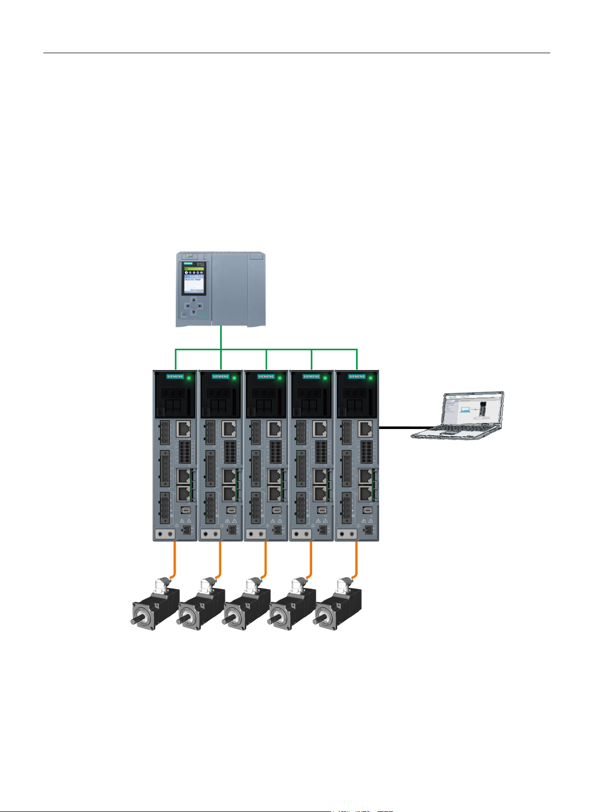
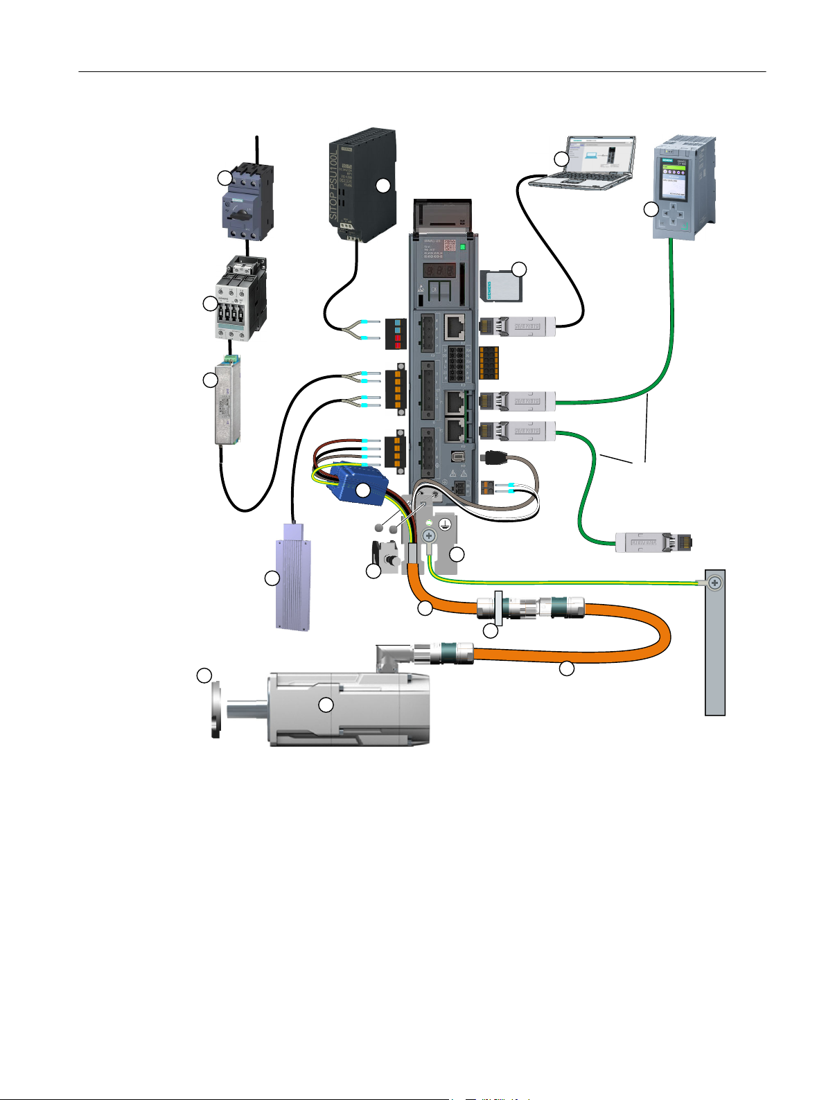
2.1 System overview
The drive system comprises the following system components tailored to one another:
● SINAMICS S210 converter
● SIMOTICS S-1FK2 motor
● OCC MOTION-CONNECT cable
The converter and the motor are optimally tailored to one another and are intended for use
with a higher-level controller (PLC). Connection to the controller is via PROFINET:
Prefabricated MOTION-CONNECT cables in various lengths are available to simply connect
the motor to the converter and to ensure safe and reliable operation.
Figure 2-1 System
22 Operating Instructions, 12/2017, A5E41702836B AA
SINAMICS S210 servo drive system
Page 25
9$&
;
;
;
;3
;
;
;
;3
;
352),1(7
352),VDIH
3(
Description
2.1 System overview
① Fuse or circuit breaker ⑨ OCC connection cable for motor, motor holding
② Line contactor (optional) ⑩ Shield clamp
③ Line filter (optional) ⑪ Shield plate
④ External braking resistor (optional) ⑫ Ferrite core (for frame size FSB)
brake and encoder
⑤ Shaft sealing ring for IP65 (optional) ⑬ 24 V power supply
⑥ 1FK2 servomotor ⑭ SD memory card (optional)
⑦ OCC extension cable (optional) ⑮ Commissioning device
⑧ Mounting flange for control cabinet
Figure 2-2 System components and accessories
bushing (optional)
⑯ Controller, e.g. SIMATIC S7-1500
SINAMICS S210 servo drive system
Operating Instructions, 12/2017, A5E41702836B AA 23
Page 26

Description
2.2 The scope of supply for the system components
2.2 The scope of supply for the system components
You must order the components individually.
Motor
The motor scope of delivery includes:
● A "Safety instructions" sheet
● A sheet referencing links to product information
Converter
The converter scope of delivery includes:
● The Quick Installation Guide (English)
● Shield plate
● A warning label for affixing in the control cabinet
● For FSB a ferrite core for EMC category C2
● The following connectors:
– X1: Line connection and external braking resistor (jumper for internal braking resistor is
enclosed.)
– X2: Motor connection
– X107: Motor holding brake
– X124: 24 V DC supply voltage
– X130: Connector for digital inputs
MOTION-CONNECT cable (OCC cable)
The scope of supply for the prefabricated MOTION-CONNECT cables includes:
● The MOTION-CONNECT cable with assembled connectors for connecting to motors and
encoders
● A shield clamp for the connection of the shield to the shield plate of the converter
● A safety data sheet
Details on the OCC MOTION-CONNECT cables can be found in the following Section:
Connection cables between the motor and the converter (Page 217).
SINAMICS S210 servo drive system
24 Operating Instructions, 12/2017, A5E41702836B AA
Page 27

2.3 Motor
The SIMOTICS S-1FK2, called "1FK2" in the following, is a permanent-magnet compact
synchronous motor with an integrated encoder and a high degree of protection.
The 1FK2 meets the requirements of standards EN 60034 and EN 60204-1 - and complies
with the Low-Voltage Directive 2014/35/EU.
Failure of pacemakers or implant malfunctions due to electromagnetic fields
Electromagnetic fields (EMF) are generated by the operation of electrical power equipment,
such as converters or motors. People with pacemakers or implants in the immediate vicinity
of this equipment are at particular risk.
Deviating from the notes in Section "General safety instructions (Page 11), applies to the
1FK2 motors:
● If you are affected, stay at a minimum distance of 30 cm from the motors.
Description
2.3 Motor
WARNING
Dynamic versions
● 1FK21 "High Dynamic" with low moment of inertia for a maximum acceleration capability
● 1FK22 "Compact" with average moment of inertia and precise positioning and synchronous
Power range
0.05 kW … 0.75 kW for a line supply voltage of 230 V 1 AC
Degree of protection
● IP64
● IP65 with a radial shaft sealing ring to protect against spray water
For additional information on the degree of protection, see Chapter:
Cooling
The 1FK2 is a non-ventilated motor.
The motor thermal losses are dissipated by thermal conduction, thermal radiation and natural
convection.
in applications with low load moments of inertia
operation characteristics for applications with a high and variable load moment of inertia
"Degree of protection (Page 180)"
If the ambient temperature exceeds 40 °C (104 °F) or the installation altitude 1000 meters
above sea level, you must reduce torque and power of the motor (derating).
Information on derating can be found in Chapter:
"Derating factors (Page 180)"
SINAMICS S210 servo drive system
Operating Instructions, 12/2017, A5E41702836B AA 25
Page 28

Description
2.3 Motor
When mounting the motor, carefully observe the specifications in Chapter:
"Cooling (Page 178)"
Bearing version
The motors have deep groove ball bearings with life-long lubrication.
The average bearing service life is designed for 25000 operating hours.
The motors have spring-loaded bearings in the NDE direction. For version with holding brake,
the NDE bearing is a locating bearing.
The permissible axial and radial forces can be found in the technical data in Chapter:
"Permissible radial and axial forces (Page 185)"
Shaft extension (IEC 60072-1)
● Cylindrical shaft without feather key
● Cylindrical shaft with feather key (half-key balancing)
● Optional for SH30 (1FK2❒03): Cylindrical shaft without feather key, diameter x length:
11 mm x 23 mm
Encoder
Holding brake
For additional information, see Chapter:
"Shaft extension (Page 183)"
The motor encoder resolution is 20 bit (1,048,576) per revolution (singleturn). An optional
multiturn encoder is available that is equipped with an additional 12-bit revolution counter
(traversing range of 4096 revolutions).
The names of these two encoders are as follows:
● AS20DQC: Absolute encoder, singleturn, 20 bit
● AM20DQC: Absolute encoder, 20 bit + 12 bit multiturn
For additional information, see Chapter:
"Available encoders (Page 185)"
The 1FK2 servomotor is available with integrated holding brake. The holding brake is used to
clamp the motor shaft when the motor is at a standstill.
The holding brake closes in the current-free state and locks the motor shaft. It opens as soon
as current is flowing.
SINAMICS S210 controls the holding brake without any additional devices.
The torsional backlash of the holding brake is less than 1°.
The holding brake is not a working brake for braking the rotating motor. However, limited
emergency stop operation is permissible.
SINAMICS S210 servo drive system
26 Operating Instructions, 12/2017, A5E41702836B AA
Page 29
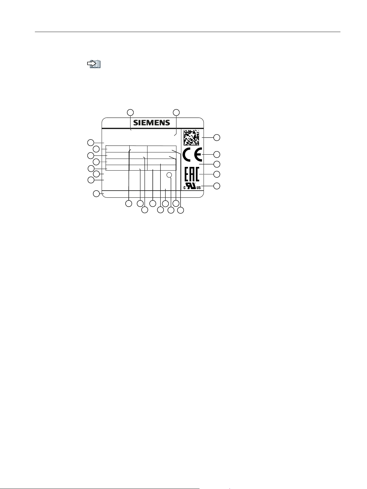
Rating plate
+
SIMOTICS 1P 1FK2104-4AK00-0CA0
M0 1,27 Nm
Brake 24 VDC
Siemens AG, DE-97616 Bad Neustadt Made in Germany
Encoder AS22DQ35 G95
3 ~ Mot. S YF JO662 2670 01 002
Z:
M
N
1,27 Nm
I0 2,4 A
IN 2,4 A
n
max
7400 /min
nn 3000 /min
UiN108 V Th.Cl.155 (F)
IP 64 IC410
RN 000
m: 3 kg
EN60034
Description
2.3 Motor
The brake data can be found in Chapter:
"Brake data (Page 185)"
The rating plate contains the Article No. and the technical information of the motor.
Figure 2-3 Rating plate
Position Description / technical specifica‐
Position Description / technical specifications
tions
1 Article number 12 Degree of protection
2 ID No., serial number 13 Rated current
3 Additional options specified as a
supplement to the article number
4 Static torque
M
/ Nm 15 Thermal class of the insulation sys‐
0
14 Cooling mode according to EN
60034-6
I
/ A
rated
tem
5 Rated torque
6 Induced voltage at rated speed
M
/ Nm 16 Revision
rated
V
/ V17 Type of balancing (only for motors
IN
with feather key)
7 Motor weight m / kg 18 Rated speed
8 Marking of encoder type 19 Maximum speed
n
rated
/ rpm
n
/ rpm
max
9 Data of the holding brake 20 Certifications
10 Manufacturer's address 21 Standard for all rotating electrical ma‐
chines
11 Stall current
I
/ A 22 Data matrix code
0
SINAMICS S210 servo drive system
Operating Instructions, 12/2017, A5E41702836B AA 27
Page 30

Description
2.4 Converter
2.4 Converter
The converter is a single-axis device (complete converter with integrated infeed). It is
characterized by a compact design, side-by-side installation and high overload capability.
It is intended for use with 1FK2 motors.
● Supply voltage 200 V … 240 V 1 AC ± 10%
●
Power range 100 W … 750 W
Control mode
Servo control, optimized for 1FK2 motors
Integrated safety functions
With firmware version 5.1, the converter provides the following Safety Integrated Basic
Functions:
● STO - Safe Torque Off
● SS1 - Safe Stop 1, time-controlled
● SBC - Safe Brake Control
Safety functions integrated in the drive (Page 57)
Integrated braking resistor
In order to absorb the regenerative load of the motor, converters have an internal braking
resistor (exception: 100 W device).
If the internal braking resistor is not sufficient, you have the option of connecting an external
braking resistor.
Configuring the external braking resistor (Page 52)
Connections at the converter (Page 95)
Communicating with the controller via PROFINET
The converter supports the following functions:
RT (real time)
●
● IRT (isochronous real time)
● MRP (media redundancy) with RT
● MRPD (seamless media redundancy) with IRT
● Shared device
● PROFIsafe
● PROFIenergy
● Automatic telegram selection
SINAMICS S210 servo drive system
28 Operating Instructions, 12/2017, A5E41702836B AA
Page 31

Commissioning, diagnostics and data backup
SINAMICS S210
1P 6SL3210-5HB10-4UF0
S ZVE4Y7M000141
SNC-A5E37577127
INPUT: 1AC 200-240V 5.8A/0.3A 50/60Hz
INPUT: 24VDC 0.5A OUTPUT: 3AC 0-INPUT V 2.6A 0-550Hz
IP CLASS: IP20 MOTOR: 0.2kW/0.4kW
VERSION: 01 SCCR: 65kA
USE IN PD2 AND OVC III ENVIRONMENT ONLY
USE 75°C COPPER WIRES ONLY | REFER TO MANUAL
KCC-
REM-S49-
S100
Siemens AG, Frauenauracher Str. 80, DE-91056 Erlangen
Made in China
IND.CONT.EQ.
4TR2
s
The commissioning, diagnostics and data backup are performed using a PC or notebook
(commissioning device) via the web server integrated in the converter.
The converter is connected to the commissioning device via the service interface (X127).
Functions of the web server integrated into the converter:
● Commissioning
● Diagnostics of the drive
● Data backup and restore
● Restoring factory settings
Rating plate and information plate
Description
2.4 Converter
1 Manufacturer 8 Environmental conditions
2 Product designation 9 Reference to the manual
3 Article number 10 Certificates
4 Serial number 11 Manufacturer's address
5 Material number 12 Production location
6 Electrical data and degree of protection 13 Data matrix code
7 Version number
Figure 2-4 Rating plate of the converter
SINAMICS S210 servo drive system
Operating Instructions, 12/2017, A5E41702836B AA 29
Page 32

PN1 / X127
FS: 01
SINAMICS S210
00-0 0-00-00-00-0 0
00-0 0-00-00-00-0 0
Description
2.4 Converter
1 Product designation 4 MAC address of the PROFINET interface
2 Function release 5 MAC address of the service interface
3 PROFINET interface / service interface 6 Data matrix code
Figure 2-5 Information plate of the converter
30 Operating Instructions, 12/2017, A5E41702836B AA
SINAMICS S210 servo drive system
Page 33

2.5 Connection systems
The motor is connected to the converter by a MOTION-CONNECT cable.
The cable is in one cable connection technology and called "OCC cable" in the following.
As a result of its flexibility and low diameter, it permits very tight bending radii.
The OCC cables are available in the following variants:
● MOTION-CONNECT 500
– Cost-effective solution for mainly fixed installation
– Suitable for low mechanical loading
● MOTION-CONNECT 800PLUS
– Meets requirements for use in cable carriers
- tested for horizontal movement distances up to 50 m
- not self-supporting
– Suitable for high mechanical loading
– Oil-resistant
Description
2.5 Connection systems
The OCC cables can be supplied in lengths by the decimeter.
Extensions and cabinet bushings are available for the OCC cables.
For additional information, see Chapter:
"Technical data and properties of the connection system (Page 204)"
SINAMICS S210 servo drive system
Operating Instructions, 12/2017, A5E41702836B AA 31
Page 34

Description
2.6 Motor-converter combinations
2.6 Motor-converter combinations
The following table contains possible combinations of motors, converters and the associated
connecting cables.
Motor Converter OCC cable
Shaft
height
[mm]
High Dynamic
20 1FK2102-0AG… 0.16 x x
20 1FK2102-1AG… 0.32 x x
30 1FK2103-2AG… 0.64 x x
30 1FK2103-4AG… 1.27 x x
40 1FK2104-4AK… 1.27 x x
40 1FK2104-5AK… 2.4 x x
Compact
30 1FK2203-2AG... 0.64 x x
30 1FK2203-4AG... 1.27 x x
Article number
digits 1 … 10
Torque
M
/ Nm 100 W 200 W 400 W 750 W M12 M17
0
Article number
6SL3210-5HB10-...
…1UF0 …2UF0 …4UF0 …8UF0 …8QN04-... …8QN08-...
Article number
6FX . 002-...
SINAMICS S210 servo drive system
32 Operating Instructions, 12/2017, A5E41702836B AA
Page 35

2.7 Optional accessories
The following accessories are optionally available for the drive:
● Memory card for the converter for data backup, series commissioning and for firmware
updates
● Line filter
● Extension cable
● Components for customers to fabricate the connecting cable
– Shield clamp
– Connectors and cut-to-length cables (probably available from spring 2018)
● Mounting flange for control cabinet bushing
● Degree of protection kit: Shaft sealing ring for IP65 degree of protection for the motor
Ordering data (Page 215)
Description
2.7 Optional accessories
SINAMICS S210 servo drive system
Operating Instructions, 12/2017, A5E41702836B AA 33
Page 36

Description
2.7 Optional accessories
SINAMICS S210 servo drive system
34 Operating Instructions, 12/2017, A5E41702836B AA
Page 37

Configuring
3.1 EMC-compliant installation of a machine or system
The converter is designed for operation in industrial environments.
Reliable and disturbance-free operation is only guaranteed for EMC-compliant installation.
Further information
Additional information about EMC-compliant installation is available in the Internet:
EMC installation guideline (http://support.automation.siemens.com/WW/view/en/60612658)
3.1.1 Control cabinet
Control cabinet assembly
● Install a shield support for shielded cables that are routed out of the control cabinet.
3
● Connect the PE bar and the shield support to the control cabinet frame through a large
surface area to establish a good electrical connection.
● Mount the converter, the 24 V DC power supply and the optional line filter on a bare metal
mounting plate.
● Connect the mounting plate to the control cabinet frame and PE bar and shield support
through a large surface area to establish a good electrical connection.
SINAMICS S210 servo drive system
Operating Instructions, 12/2017, A5E41702836B AA 35
Page 38

Configuring
3.1 EMC-compliant installation of a machine or system
3.1.2 Cables
Cables with a high level of interference and cables with a low level of interference are
connected to the converter.
Note
Cables with a high level of interference must be shielded.
● Cables with a high level of interference:
– Cable between the line filter and converter
– Motor cable
– Cable between the converter and external braking resistor
● Cables with a low level of interference:
– Cable between the line and line filter
– Signal and data cables
Cable routing inside the cabinet
● Route the cables with a high level of interference so that there is the largest possible
clearance to cables with a low level of interference.
● Cables with a high level of interference and cables with a low level of interference may only
cross over at right angles:
● Keep all of the cables as short as possible.
● Route all of the cables close to the mounting plates or cabinet frames.
● Route signal and data cables - as well as the associated equipotential bonding cables parallel and close to one another.
● Twist incoming and outgoing unshielded individual conductors.
Alternatively, you can route incoming and outgoing conductors in parallel, but close to one
another.
● Ground any unused conductors of signal and data cables at both ends.
● Signal and data cables must only enter the cabinet from one side, e.g. from below.
● Use shielded cables for the following connections:
– Cable between the converter and line filter
– Cable between the converter and motor
– Cable between the converter and external braking resistor
SINAMICS S210 servo drive system
36 Operating Instructions, 12/2017, A5E41702836B AA
Page 39

0RXQWLQJSODWH
6KLHOGVXSSRUW
)XVHVVZLWFKHVDQG
FRQWDFWRUV
)LOWHURSWLRQDO
&RQYHUWHU
&RQQHFWVKLHOG
(OHFWULFDOO\
FRQGXFWLYH
FRQQHFWLRQV
WKURXJKDODUJH
VXUIDFHDUHD
%UDNLQJUHVLVWRU
RSWLRQDO
&RQWUROFDELQHW
/LQH
&RQQHFWVKLHOG
&RQQHFWVKLHOG
3.1 EMC-compliant installation of a machine or system
Routing converter cables inside and outside a control cabinet
Configuring
Figure 3-1 Routing converter cables inside and outside a control cabinet
Routing cables outside the control cabinet
● Maintain a minimum clearance of 25 cm between cables with a high level of interference
and cables with a low level of interference.
● Use shielded cables for the following connections:
– Converter motor cable
– Cable between the converter and braking resistor
– Signal and data cables
SINAMICS S210 servo drive system
Operating Instructions, 12/2017, A5E41702836B AA 37
Page 40

2&&FRQQHFWLRQFDEOHWRWKH
PRWRU
)HUULWHFRUHUHTXLUHGIRU)6%
IRU(0&&DWHJRU\&
&RQQHFWLRQFDEOHIRUH[WHUQDO
EUDNLQJUHVLVWRU
&RQQHFWLRQFDEOHIRUIDLOVDIHGLJLWDO
LQSXWDQGSUREH
Configuring
3.1 EMC-compliant installation of a machine or system
Requirements relating to shielded cables
● Use cables with finely-stranded, braided shields.
● Connect the shield at both ends of the cable.
Figure 3-2 Shield support with the shield terminal from the scope of supply of the MOTION-
CONNECT OCC cable.
● Connect the shield to the shield support.
● Do not interrupt the shield.
3.1.3 Electromechanical components
Surge voltage protection circuit
● Connect surge voltage protection circuits to the following components:
– Coils of contactors
– Relays
– Solenoid valves
● Connect the surge voltage protection circuit directly at the coil.
● Use RC elements or varistors for AC-operated coils and freewheeling diodes or varistors
for DC-operated coils.
38 Operating Instructions, 12/2017, A5E41702836B AA
SINAMICS S210 servo drive system
Page 41

3.2 Permissible line supplies and connection options
3.2 Permissible line supplies and connection options
The converter is designed for the following line supplies according to IEC 60364-1 (2005).
● TN system
● TT system
● IT system
Converter operated on an IT system
You must move the grounding screw when operating the converter on an IT line system. As
a consequence, you remove the grounding of the integrated EMC filter.
Configuring
Figure 3-3 Screw for grounding at the converter
SINAMICS S210 servo drive system
Operating Instructions, 12/2017, A5E41702836B AA 39
Page 42

1RWUDQVIRUPHUUHTXLUHG
1RWUDQVIRUPHUUHTXLUHG1RWHWKH
IROORZLQJVDIHW\LQVWUXFWLRQV
UHJDUGLQJWKHFXUUHQWVLQWKH
QHXWUDOFRQGXFWRU
7UDQVIRUPHUUHTXLUHG7UDQVIRUPHUUHTXLUHG
1RWUDQVIRUPHUUHTXLUHG
1RWUDQVIRUPHUUHTXLUHG
/
1
$&99
$&99
9
9
9
1
$&99
/
/
/
1
/
1
$&9
/
/
/
1
$&99$&99
/
/
/
Configuring
3.2 Permissible line supplies and connection options
3.2.1 Connection options, 230 V devices
Basic connection options
You have the following options to supply the converter with an input voltage of 230 V.
Figure 3-4 Connection options
SINAMICS S210 servo drive system
40 Operating Instructions, 12/2017, A5E41702836B AA
Page 43

Configuring
3.2 Permissible line supplies and connection options
WARNING
Neutral conductor fire caused by high currents
If you connect the converter without an isolation transformer to a supply system with 400 V
3 AC between the N-conductor and a line conductor (L1, L2 or L3), the harmonic currents in
the N-conductor can add up to values that are greater than the currents in the line conductors.
This heats up the N-conductor and can cause a fire.
● Take the harmonic currents into account when dimensioning the power supply cables.
SINAMICS S210 servo drive system
Operating Instructions, 12/2017, A5E41702836B AA 41
Page 44

)
$&9
/
1
Configuring
3.2 Permissible line supplies and connection options
Connection examples and cable cross-sections
① Line filter (optional) ② Group terminals
Sum of the input currents of all converters ≤ 24 A
● Fuses:
3NA3812 or class J 30 A for UL/CSA
● Cables for the line connection up to the terminal box
4 mm2, dimensioned for
● Cables for the connection from the terminal box to the converter
2.5 mm2, dimensioned for
Figure 3-5 Connection example for 230 V 1 AC
I
≥ 32 A
rms
I
≥ 18.5 A at 50 °C
rms
at 50 °C
rms
SINAMICS S210 servo drive system
42 Operating Instructions, 12/2017, A5E41702836B AA
Page 45

/
/
/
1
))
$&9
Configuring
3.2 Permissible line supplies and connection options
① Line filter (optional) ② Group terminals
Sum of the input currents of all converters per phase ≤ 24 A
● Fuses, F1 … F3
3NA3812 or class J 30 A for UL/CSA
● Cables for the connection from the terminal box to the converter
● Cables for the line connection up to the terminal box
Figure 3-6 Connection example for 400 V 3 AC
4 mm2, dimensioned for
2.5 mm2, dimensioned for
I
≥ 32 A at 50 °C
rms
I
≥ 18.5 A at 50 °C
rms
SINAMICS S210 servo drive system
Operating Instructions, 12/2017, A5E41702836B AA 43
Page 46

Configuring
3.3 Configuring the motor
3.3 Configuring the motor
3.3.1 Configuration sequence
Motion control
Drives are optimized for motion control applications. They execute linear or rotary movements
within a defined movement cycle. All movements should be optimized in terms of time.
As a result, drives must meet the following requirements:
● High dynamic response, i.e. short rise times
● Capable of overload, i.e. a high reserve for accelerating
● Wide control range, i.e. high resolution for precise positioning.
The following table "Configuring procedure" is valid for synchronous and induction motors.
General configuring procedure
The function description of the machine provides the basis when configuring the drive
application. The definition of the components is based on physical interdependencies and is
usually carried out as follows:
Table 3-1 Configuring procedure
step Description of the configuring activity
1. Clarification of the type of drive Refer to the
2. Definition of supplementary conditions and integration into an automation sys‐
tem
3. Definition of the load, calculation of the maximum load torque and selection
of the motor
next chapter
SINAMICS S210 servo drive system
44 Operating Instructions, 12/2017, A5E41702836B AA
Page 47

Configuring
3.3 Configuring the motor
step Description of the configuring activity
4. Selection of the SINAMICS Motor Module Refer to
5. Steps 3 and 4 are repeated for additional axes
6. Calculation of the required DC link power and selection of the SINAMICS Line
Module
7. Selection of the line-side options (main switch, fuses, line filters, etc.)
8. Specification of the required control performance and selection of the Control
Unit, definition of component cabling
9. Definition of other system components (e.g. braking resistors)
10. Calculation of the current demand of the 24 V DC supply for the components
and specification of the power supplies (SITOP devices, Control Supply Mod‐
ules)
11. Selection of the components for the connection system
12. Configuration of the drive line-up components
13. Calculation of the required cable cross sections for power supply and motor
connections
14. Inclusion of mandatory installation clearances
catalog
3.3.1.1 Clarification of type of drive
Select the motor on the basis of the required torque (load torque), which is defined by the
application, e.g. traveling drives, hoisting drives, test stands, centrifuges, paper and rolling mill
drives, feed drives or main spindle drives.
Gearboxes to convert motion or to adapt the motor speed and motor torque to the load
conditions must also be taken into account when selecting the motor.
You must know the following mechanical data in order to determine the torque to be supplied
by the motor:
● The load torque specified by the application
● Masses to be moved
● Diameter of the drive wheel
● Leadscrew pitch, gear ratios
● Frictional resistance data
● Mechanical efficiency
● Traversing distances
● Maximum velocity
● Maximum acceleration and maximum deceleration
● Cycle time
SINAMICS S210 servo drive system
Operating Instructions, 12/2017, A5E41702836B AA 45
Page 48

7RUTXHLQ1P
0RWRUVSHHGLQUSP
6
0BPD[
Configuring
3.3 Configuring the motor
3.3.1.2 Specification of the supplementary conditions and integration into the automation system
Take the following into account during the confguration:
● The line system configuration when using specific motor types and/or line filters
● The utilization of the motor rated values for winding overtemperatures of 60 K or 100 K (for
synchronous motors)
● The ambient temperatures and the installation altitude of the motors and drive components
● The heat dissipation from the motors through natural ventilation, forced ventilation or water
cooling
Other conditions apply when integrating the drives into an automation environment such as
SINUMERIK or SIMOTION.
For motion control and technology functions (e.g. positioning), as well as for synchronous
operation functions, the corresponding automation system, e.g. SIMATIC S7-1500 or
SIMOTION D is used.
3.3.1.3 Definition of the load, calculation of the maximum load torque and determination of the motor
The motors are defined bases on the motor type-specific limiting characteristic curves.
The limiting characteristic curves describe the torque or power curve over the speed.
The limiting characteristic curves take the limits of the motor into account on the basis of the
DC-link voltage. The DC-link voltage is dependent on the line voltage.
In the case of torque drive the DC-link voltage is dependent on the type of Line Module and
the type of infeed module or infeed/regenerative feedback module.
M_max Curve of the maximum torque
S1 S1 characteristic
Figure 3-7 Limiting characteristic for synchronous motors 1FK2
46 Operating Instructions, 12/2017, A5E41702836B AA
SINAMICS S210 servo drive system
Page 49

PD[
W
W
9
3
3
˽
˽
Configuring
3.3 Configuring the motor
Procedure
1. Determine the load which is specified by the application.
Use different characteristics for the different loads.
The following operating scenarios have been defined:
– Duty cycle with constant ON duration
– Free duty cycle
2. Determine the characteristic torque and speed operating points of the motor for the defined
load.
3. Calculate the acceleration torque of the motor.
Add the load torque and the acceleration torque to obtain the maximum required torque.
4. Verify the maximum motor torque with the limiting characteristic curves of the motors.
The following criteria must be taken into account when selecting the motor:
– Adherence to the dynamic limits
All speed-torque points of the load event must lie below the relevant limiting
characteristic curve.
– Adherence to the thermal limits
At average motor speed, the effective motor torque must be below the S1 characteristic
(continuous operation) during the load.
You have specified a motor.
Duty cycles with constant ON duration
For duty cycles with constant ON duration, there are specific requirements for the torque
characteristic curve as a function of the speed, for example:
M = constant, M ~ n2, M ~ n or P = constant.
Figure 3-8 S1 duty (continuous operation)
The drives with this load cycle typically operate at a stationary operating point.
SINAMICS S210 servo drive system
Operating Instructions, 12/2017, A5E41702836B AA 47
Page 50

7RUTXHLQ1P
0RWRUVSHHGLQUSP
6
0BPD[
0BFRQVWBRYHU
0BFRQVWBEDVH
Configuring
3.3 Configuring the motor
Procedure
1. Configure a base load for the stationary operating point. The base load torque must lie
below the S1 characteristic.
2. In the event of transient overloads (e.g. during acceleration), configure an overload.
Calculate the overload current in relation to the required overload torque. The overload
torque must lie below the M_max characteristic.
In summary, the motor is configured as follows:
M_max Curve of the maximum torque M_const_overCurve of the overload torque
S1 S1 characteristic M_const_b
Curve of the base load torque
ase
Figure 3-9 Motor selection for a duty cycle with constant switch-on duration
3. Select a motor that satisfies the requirements of S1 duty.
48 Operating Instructions, 12/2017, A5E41702836B AA
SINAMICS S210 servo drive system
Page 51

Free duty cycle
W
W
L
W7
Q
0
WR0L
0
*
WV/DL
L
WV/D
Ws/DL
L
tV/DL
5
*
M J J
n
t
i J
n
t
M M
i
=
+ •
2
06
• • +
(
•
2
06
• + +
)
•
1
•
)(
= •
n n i
WR0LWV/DL
T
0 RWL
L
0RWHII
2
=
•
M
M
t
Δ
∑
=
+
2
•
n
n n
t
0RWPLWWHO
0RWL$0RWL(
L
T
3.3 Configuring the motor
A free duty cycle defines the curve of the motor speed and the torque over time.
n Speed T Cycle time
M Torque Δt
t Time
Figure 3-10 Example of free duty cycle
i
Time interval
Configuring
Procedure
Determine the required motor torque as follows:
● Define a load torque for each time slice. Also take the average load moment of inertia and
motor moment of inertia into account for acceleration operations. If required, take a frictional
torque into account that opposes the direction of motion.
● With mounted gearbox:
Determine the load torque and the acceleration torque that must be supplied by the motor.
Take the gear ratio and gear efficiency into account.
Note
A higher gear ratio increases positioning accuracy in terms of encoder resolution. For any
given motor encoder resolution, as the gear ratio increases, so does the resolution of the
machine position to be detected.
The following formulas can be used for duty cycles outside the field weakening range.
For the motor torque in a time slice Δ
t
the following applies:
i
The motor speed is:
The effective torque is obtained as follows:
The average motor speed is calculated as follows:
SINAMICS S210 servo drive system
Operating Instructions, 12/2017, A5E41702836B AA 49
Page 52

7RUTXHLQ1P
0RWRUVSHHGLQUSP
6
0BPD[
0BPD[IURPWUDYHUVLQJSURILOH
0BHII
QBPHDQ
Configuring
3.3 Configuring the motor
J
M
J
G
J
load
n
load
i
η
G
M
load
M
R
T
A; E Initial value, final value in time slice Δ
t
e
∆
t
i
The effective torque M
The maximum torque M
Motor moment of inertia
Gearbox moment of inertia
Load moment of inertia
Load speed
Gear ratio
Gearbox efficiency
Load torque
Frictional torque
Cycle time
ON duration
Time interval
must lie below the S1 characteristic.
eff
is produced during the acceleration operation. M
max
t
i
must lie below
max
the voltage limiting characteristic curve. In summary, the motor is configured as follows:
M_max Curve of the maximum torque S1 S1 characteristic = M
0
M_eff Effective torque ● Points from the traversing profile
n_mean Mean speed
Figure 3-11 Motor selection for duty cycle
You have defined the characteristic motor values corresponding to the duty cycle.
50 Operating Instructions, 12/2017, A5E41702836B AA
SINAMICS S210 servo drive system
Page 53

Specification of the motor
By varying, you can find the motor that satisfies the conditions of the operating mode (duty
cycle).
● Determine the motor current at base load. The calculation depends on the type of motor
(synchronous motor or induction motor) and the operating mode (duty cycle) used.
Note
When configuring according to duty cycle with constant ON duration with overload, the
overload current is calculated in relation to the required overload torque.
● Comply with the thermal limits of the motor.
● Configure the other properties of the motor through the available motor options.
Configuring
3.3 Configuring the motor
SINAMICS S210 servo drive system
Operating Instructions, 12/2017, A5E41702836B AA 51
Page 54

Configuring
3.4 Configuring the external braking resistor
3.4 Configuring the external braking resistor
The converter has a Braking Module that converts regenerative energy of the servo motors
into heat via an integrated braking resistor. Regenerative energy is produced, for example,
when braking the connected mechanical system.
The continuous braking power and the braking energy that the integrated braking resistor can
convert into heat are listed in the following table:
Table 3-2 Braking energy and continuous braking power with the integrated braking resistor in
relation to the shaft of the servo motor
Converter Braking energy
Article number Power [W]
6SL3210-5HB10-1UF0 100 20 5
6SL3210-5HB10-2UF0 200 570 10
6SL3210-5HB10-4UF0 400 840 20
6SL3210-5HB10-8UF0 750 1680 40
When do you require an external braking resistor?
Applications with frequent and very fast braking processes are typical applications that may
require an external braking resistor.
To find out whether you require an external braking resistor, calculate the braking energy that
you require according to the following formula:
W = 0.5 (J
J
mot
J Moment of inertia of the driven mechanical system in relation to the shaft of the servo
+ J ) x 4π² / 3600 x (
Mot
Moment of inertia of the servomotor
High Dynamic (Page 187)
Compact (Page 194)
motor
Continuous braking
[J]
n
² +
n
1
²)
2
power
[W]
Note
As the actual friction is not taken into account in the above formula, less energy is fed back to
the servo drive system in practice than that calculated in the formula.
Example
Moment of inertia of the servomotor 1FK2104-2AG1
Moment of inertia of the driven mechanical system
n
= 3000 rpm
1
n
= 600 rpm
2
J
= 0.75 × 10⁻⁴ kg m
mot
J
= 4 ×10⁻⁴ kg m
⇒ W = 22.5 J (1 J = 1 Ws)
SINAMICS S210 servo drive system
52 Operating Instructions, 12/2017, A5E41702836B AA
2
2
Page 55

Configuring
3.4 Configuring the external braking resistor
Requirements placed on the external braking resistor
WARNING
Risk of fire caused by continuous overload
If the external braking resistor is continuously overloaded, for example as the result of a
defective braking chopper, this can result in an explosion or fire - or the housing could melt.
● Use only braking resistors that are intrinsically safe.
Table 3-3 Resistance data for an external braking resistor
Converter Braking resistor
Article number Power
[W]
6SL3210-5HB10-1UF0 100
6SL3210-5HB10-2UF0 200
6SL3210-5HB10-4UF0 400 100 1.64 1.23 21
6SL3210-5HB10-8UF0 750 50 3.28 2.46 62
Resistance
[Ω]
150 1.09 0.8 20
Peak braking pow‐
er
[kW]
Braking energy
[kJ]
Rated power
[W]
Table 3-4 Examples of suitable external braking resistors from a third party
Converter Braking resistor
Article number Power
[W]
6SL3210-5HB10-1UF0 100 50 1.1 Michael Koch GmbH, BWG250150
6SL3210-5HB10-2UF0 200 100 1.1 Michael Koch GmbH, BWG250150
6SL3210-5HB10-4UF0 400 200 1.7 Michael Koch GmbH, BWG500100
6SL3210-5HB10-8UF0 750 240 3.6 Michael Koch GmbH, BWG600047
1) For thermal reasons, it is not permissible that the continuous braking power of 240 W is exceeded.
Continuous braking
power of the brake
chopper
[W]
Peak braking pow‐
er
[kW]
Example of manufacturer or equiva‐
lent
Note
Braking resistor with temperature monitoring
Use only a braking resistor with temperature monitoring.
Connecting the external braking resistor
Use shielded cables to connect power to the external braking resistor.
How to connect the external braking resistor and the temperature monitoring is described in
the following Sections:
1)
Connections for open-loop and closed-loop control of the converter (Page 101).
SINAMICS S210 servo drive system
Operating Instructions, 12/2017, A5E41702836B AA 53
Page 56

Configuring
3.4 Configuring the external braking resistor
Setting the temperature monitoring of the external braking resistor
If you have connected the external braking resistor with motor temperature monitoring, you
must activate the temperature monitoring via the web server of the converter.
Configuring digital inputs (Page 127).
Activate the digital input DI 4 "Temperature monitoring of the external braking resistor".
The converter switches the motor off as soon as the external braking resistor is too hot or when
no external braking resistor is connected (wire break).
SINAMICS S210 servo drive system
54 Operating Instructions, 12/2017, A5E41702836B AA
Page 57

Configuring
3.5 Establishing communication of the converter with the controller
3.5 Establishing communication of the converter with the controller
You only have to create the communication settings between the converter and the PLC in the
corresponding PLC.
The converter takes over the telegram settings from the PLC during run-up.
You can create one standard telegram and two different supplementary or safety telegrams
for the converter.
The converter supports the following telegrams:
Standard telegrams:
● Telegram 3
● Telegram 5
● Telegram 102
● Telegram 105
Supplementary telegrams
● Telegram 700
● Telegram 701
● Telegram 750
PROFIsafe telegrams
● Telegram 30
● Telegram 901
For further information about telegrams
Communication telegrams (Page 737)
SINAMICS S210 servo drive system
Operating Instructions, 12/2017, A5E41702836B AA 55
Page 58

Configuring
3.5 Establishing communication of the converter with the controller
SINAMICS S210 servo drive system
56 Operating Instructions, 12/2017, A5E41702836B AA
Page 59

Safety functions integrated in the drive
4.1 Overview of Safety Integrated Functions
In comparison to standard drive functions, safety functions have an especially low error rate.
Performance level (PL) and safety integrity level (SIL) of the corresponding standards are a
measure of the error rate.
As a consequence, the safety functions are suitable for use in safety-related applications to
minimize risk. An application is safety-related if the risk analysis of the machine or the system
indicates a special hazard potential in the application.
Safety Integrated ("drive-integrated") means that the safety functions are integrated in the
converter and can be executed without requiring additional external components.
You make the settings for these Safety Integrated Functions via the web server. Take the
instruction in the following section into account:
Safety settings in the Web server (Page 135)
Overview of Safety Integrated Functions
The Safety Integrated Functions comply with:
● Safety Integrity Level (SIL) 2 according to DIN EN 61508
4
Basic Functions
● Category 3 according to DIN EN ISO 13849‑1
● Performance level (PL) d according to DIN EN ISO 13849-1
The Safety Integrated Functions correspond to the functions according to EN 61800‑5‑2.
These functions are part of the standard scope of the converter and can be used without
requiring an additional license. The Basic Functions consist of the following Safety Integrated
Functions:
● Safe Torque Off (STO)
● Safe Brake Control (SBC)
● Safe Stop 1, time-controlled (SS1)
SINAMICS S210 servo drive system
Operating Instructions, 12/2017, A5E41702836B AA 57
Page 60

672
v
t
Safety functions integrated in the drive
4.2 Basic Functions
4.2 Basic Functions
4.2.1 Safe Torque Off (STO)
Overview
Safe Torque Off (STO) is a safety function that
immediately ensures that torque or force-gen‐
erating energy is not fed to the motor. This
function corresponds to stop category 0 to
EN 60204-1.
If the motor is still rotating when STO is selec‐
ted, then it coasts down to standstill.
Functional features
The switching on inhibited prevents an automatic restart after deselection of STO and therefore
satisfies the requirements of EN 60204-1. Consequently, the STO function prevents an
electrically-driven machine component from restarting.
Note
There is no galvanic isolation between motor and converter.
The STO function can be selected via PROFIsafe and/or the fail-safe digital input (F-DI).
STO is a drive-specific function that must be put into operation individually for each drive.
Applications
Applications include all machines and systems with moving axes (e.g. conveyor technology,
handling).
STO is suitable for applications where the motor is already at a standstill or will come to a
standstill in a short, safe period of time as a result of friction.
58 Operating Instructions, 12/2017, A5E41702836B AA
SINAMICS S210 servo drive system
Page 61

Sequence diagram
7KHPRWRUFRDVWV
GRZQWRDVWDQGVWLOO
6SHHG
W
W
W
672DFWLYH
672GHVHOHFWLRQ
212))
5HDG\WRVWDUW
$FWLRQ0RWRU
UHVSRQVH
&RQYHUWHU
UHVSRQVH
Safety functions integrated in the drive
4.2 Basic Functions
STO facilitates personnel to work safely with the protective door open. A classic Emergency
Stop with electromechanical isolation is not required. The converter remains connected to the
line and can be fully diagnosed.
Note
The distinction between Emergency Off and Emergency Stop
"Emergency Off" and "Emergency Stop" are commands that minimize different risks in the
machine or plant.
The STO function is suitable for implementing an Emergency Stop - but not an Emergency Off.
Details regarding the distinction between Emergency Off and Emergency Stop are provided
in the following section:
What is the difference between the Emergency Off and Emergency Stop functions?
(Page 745)
During operation, STO is selected via PROFIsafe or F-DI.
The converter signals the status to the PLC via PROFIsafe for further processing.
After the response time, the drive immediately initiates safe pulse suppression. This interrupts the
torque-generating energy fed to the motor. The motor coasts down to a standstill. STO safely
prevents an unwanted restart of the motor.
Restart:
The converter goes into the "Ready to start" state, when STO is deselected via PROFIsafe or FDI.
The converter switches the motor on again with a positive signal edge at ON/OFF.
Selecting/deselecting "Safe Torque Off"
SINAMICS S210 servo drive system
Operating Instructions, 12/2017, A5E41702836B AA 59
If "Safe Torque Off" is selected, the motor holding brake is closed (if connected and configured).
Page 62

Safety functions integrated in the drive
4.2 Basic Functions
Deselecting "Safe Torque Off" represents an internal safety acknowledgment. The following
is executed when the cause of the fault has been removed:
1. The Safety requirement "Close motor holding brake" is canceled.
2. Any pending STOP F or STOP A commands are canceled.
3. The messages in the fault memory must also be reset using the general acknowledgment
mechanism.
SINAMICS S210 servo drive system
60 Operating Instructions, 12/2017, A5E41702836B AA
Page 63

4.2.2 Safe Brake Control (SBC)
672
6%&
v
t
Overview
Functional features
In order that SBC can become active you must enable the function when commissioning the
system.
Safety functions integrated in the drive
4.2 Basic Functions
The "Safe Brake Control" function (SBC) is
used to safely control the motor-integrated
holding brake.
The holding brake opens as soon as voltage is
available - and closes when in the no-voltage
state.
Applications
Note
SBC cannot be selected as an autonomous function; however, if it is enabled, it is activated
at the same time that STO is selected.
The holding brake is controlled using the encoder integrated in the motor.
SBC can be used wherever a safe position must be maintained even with a de-energized
motor, in order to prevent suspended or passing loads from dropping (e.g. lifting gear,
passenger elevators, winders). No external logic or switching elements required, as the
functionality is completely integrated in the drive.
Note
Condition of the motor holding brake
SBC is not able to identify as to whether a holding brake is mechanically worn or is a defective.
As a consequence, observe the maximum permissible number of emergency braking
operations for the motor holding brake being used.
SINAMICS S210 servo drive system
Operating Instructions, 12/2017, A5E41702836B AA 61
Page 64

212))
2SHQPRWRUKROGLQJEUDNH
$FWLRQ0RWRU
UHVSRQVH
&RQYHUWHUUHVSRQVH
0RWRUKROGLQJEUDNHRSHQ
672GHVHOHFWLRQ
6SHHG
672DFWLYH
6%&UHTXHVWHG
5HDG\IRUVZLWFKLQJ
0RWRUEUDNHVWR
VWDQGVWLOO
7LPHIRUEUDNHRSHQLQJRSHUDWLRQ
7LPHIRUEUDNHFORVLQJRSHUDWLRQ
W
W
W
0
0
0
Safety functions integrated in the drive
4.2 Basic Functions
Sequence diagram
STO is selected during operation via the control bit of the selected PROFIsafe telegram or via the
F-DI.
Safe Brake Control (SBC) is activated at the same time. Taking the brake closing time (r1217)
into account, the command to close the motor holding brake closes the brake, thus supporting the
shutdown process initiated by STO.
The mechanical brake brakes the motor down to standstill.
The converter goes into the "Ready to start" state, when STO is deselected via PROFIsafe or F-
DI. SBC is reset at the same time. The brake remains (unsafely) closed until the standard program
executes the command to open the brake.
The converter switches the motor on again with a positive signal edge at ON/OFF.
Taking the brake opening time (r1216) into account, the command to open the motor holding brake
opens the brake.
The converter carries out a check to ensure that the "Safe Brake Control" function is working
properly and ensures that - if there is a failure or fault - the brake current is interrupted and the
brake is thus applied. If a fault is detected by the converter, the brake current is
disconnected. The brake then closes and a safe state is reached.
62 Operating Instructions, 12/2017, A5E41702836B AA
SINAMICS S210 servo drive system
Page 65

4.2.3 Safe Stop 1 (SS1, time-controlled)
672
∆t
t
v
Overview
Functional features
There are the following variants for the Basic Function "Safe Stop 1":
● SS1 with OFF3 (SS1-t according to IEC 61800-5-2)
Safety functions integrated in the drive
4.2 Basic Functions
The "Safe Stop 1" function (SS1, time-control‐
led) causes a drive-autonomous deceleration
of the motor and initiates the "Safe Torque Off"
(STO) function after a predefined time interval
has elapsed. This function corresponds to stop
category 1 to EN 60204‑1.
● SS1 with external stop (SS1E)
The setting of the SS1 response is performed during the Safety commissioning in the step
"Parameterization"
Applications
SS1 can be used wherever the load torque cannot stop the motor in a sufficiently short time
as a result of friction - or where there is a safety risk if the drive coasts down (STO).
SS1 with OFF3 (SS1-t)
When SS1-t is selected, the motor speed is reduced along the OFF3 ramp for the duration of
the selected delay time. After the delay time expires, the converter activates the STO function
(independent of the actual speed).
Note
There is a single-channel monitoring of the braking process at the OFF3 ramp!
SINAMICS S210 servo drive system
Operating Instructions, 12/2017, A5E41702836B AA 63
Page 66

'HOD\WLPH
7KHPRWRUFRDVWVGRZQ
WRDVWDQGVWLOO
6SHHG
W
W
66DFWLYH
672DFWLYH
W
'HVHOHFW66
212))
5HDG\WRVWDUW
$FWLRQ0RWRU
UHVSRQVH
&RQYHUWHU
UHVSRQVH
Safety functions integrated in the drive
4.2 Basic Functions
Flow diagram SS1 with OFF3 (SS1-t)
SS1 is selected during operation (selection via the control bit of the selected PROFIsafe telegram
or via F-DI).
The converter signals the status "SS1 active" via the status bit of the PROFIsafe telegram to the
PLC for further processing.
After the response time, the converter initiates braking along the OFF3 ramp. The SS1 delay time
is started at the same time.
The converter brakes the motor along the OFF3 ramp for the duration of the delay time.
STO is initiated automatically after the SS1 delay time expires (p9652).
The motor coasts down to a standstill. STO safely prevents an unwanted restart of the motor.
When SS1 is deselected (via PROFIsafe or F-DI), STO and SS1 are deactivated and the converter
goes into the "Ready for switching on" state.
The converter switches the motor on again with a positive signal edge at ON/OFF.
Shutting down the motor with SS1 active
When SS1 is active, the OFF2 command stops the energy supply to the motor, even before
the delay time for SS1 has elapsed. The motor coasts down to a standstill.
Proceed as follows in order to switch on the motor again:
1. Deselect SS1. This deactivates SS1 and STO.
2. Deselect the OFF2 command. The converter goes into the "Ready for switching on" state.
3. Switch the motor off and back on to send an ON signal to the motor.
64 Operating Instructions, 12/2017, A5E41702836B AA
SINAMICS S210 servo drive system
Page 67

Note
OFF1 or OFF3 for active SS1
Switching the motor off via an OFF1 or OFF3 command while SS1 is active (e.g. by a limit
switch) does not influence the response of converter and motor.
SS1 remains active after the OFF command. After the delay time has elapsed, the converter
transitions to STO status.
SS1 with external stop (SS1E)
If several drives are connected with one another through a material web, then braking initiated
by a single drive at the related OFF3 ramp can damage the machine or system.
When the safety function SS1E is used, the drive is shut down using the user program of a
higher-level control system. Although the safe delay time is activated when SS1E is selected,
OFF3 is not activated. The converter signals via PROFIsafe or the Safety Info Channel (SIC)
of the supplementary telegram that SS1 was selected. Using an appropriate program, the
control must then ramp down the drives involved within the delay time to the safe state. After
the delay time has elapsed, the converter activates the STO function and safely interrupts the
energy feed to the motor (independent of the actual speed).
Safety functions integrated in the drive
4.2 Basic Functions
SINAMICS S210 servo drive system
Operating Instructions, 12/2017, A5E41702836B AA 65
Page 68

'HOD\WLPH
7KHPRWRUFRDVWVGRZQ
WRDVWDQGVWLOO
6SHHG
W
W
66DFWLYH
672DFWLYH
W
'HVHOHFW66
212))
5HDG\WRVWDUW
$FWLRQ0RWRU
UHVSRQVH
&RQYHUWHU
UHVSRQVH
Safety functions integrated in the drive
4.2 Basic Functions
Flow diagram SS1 with external stop (SS1E)
SS1E is selected during operation (selection via the control bit of the selected PROFIsafe telegram
or via F-DI).
The converter signals the status "SS1 active" via the status bit of the PROFIsafe telegram to the
PLC for further processing.
The control system triggers the shutdown via the setpoint input. The SS1 delay time in the con‐
verter is started at the same time.
The motor is braked by the external setpoint input, and signals "SS1E selected" to the PLC.
STO is initiated automatically after the SS1 delay time expires (p9652).
The motor coasts down to a standstill. STO safely prevents an unwanted restart of the motor.
When SS1 is deselected (via PROFIsafe or F-DI), STO and SS1 are deactivated and the converter
goes into the "Ready for switching on" state.
The converter switches the motor on again with a positive signal edge at ON/OFF.
Note
SS1 cannot be interrupted
If SS1 is deselected again during this time, the STO function is selected and deselected again
immediately after the delay time has elapsed or the speed has dropped below the shutdown
speed. This terminates the SS1 function normally. It cannot be interrupted.
Setting the delay time for SS1
Select the SS1 delay time such that the converter can brake the motor down to standstill along
the OFF3 ramp in any state of the work process.
The OFF3 ramp-down time must be orientated to the actual braking capacity of the system or
machine.
66 Operating Instructions, 12/2017, A5E41702836B AA
SINAMICS S210 servo drive system
Page 69

Safety functions integrated in the drive
4.2 Basic Functions
Use the following procedure to select the SS1 delay time:
SS1 delay time with parameterized motor holding brake:
SS1 delay time (p9652) ≥ OFF3 ramp-down time (p1135) + pulse suppression delay time
(p1228) + motor holding brake closing time (p1217)
SS1 delay time, without parameterized motor holding brake:
SS1 delay time (p9652) ≥ OFF3 ramp-down time (p1135) + pulse suppression delay time
(p1228)
SINAMICS S210 servo drive system
Operating Instructions, 12/2017, A5E41702836B AA 67
Page 70

Safety functions integrated in the drive
4.3 Configuring the safety functions
4.3 Configuring the safety functions
When configuring the safety functions, you specify the interfaces that activate the safety
functions.
Selection via F-DI
You can select or deselect the safety function via the fail-safe digital input (F-DI).
Whether STO or SS1 is activated when you select the safety function depends on the setting
of the SS1 delay time:
● SS1 delay time = 0: STO is activated immediately
● SS1 delay time > 0: SS1 is activated; STO is activated after the SS1 delay time has expired
Selection via PROFIsafe
The following safety telegrams are available for the safety functions via PROFIsafe:
● Telegram 30
● Telegram 901
Details of telegrams and control word and status word assignments can be found in section
Communication telegrams (Page 737).
Selection via PROFINET
The following supplementary telegrams are available for the safety functions via PROFINET:
● Telegram 700
● Telegram 701
Details of telegrams and control word and status word assignments can be found in section
Communication telegrams (Page 737).
SINAMICS S210 servo drive system
68 Operating Instructions, 12/2017, A5E41702836B AA
Page 71

4.4 Responses to safety faults
4.4.1 Stop responses
Overview
If Basic Function faults occur, the following stop responses can be triggered:
● STOP A
● STOP F
Internal event
An "internal event" is a major fault that causes the converter to bring the motor to a standstill
as quickly as possible by triggering a STOP reaction.
An "internal event" can be triggered, for example, if the converter detects a fault in the
monitoring channels during a data cross-check (e.g. F01611 "Defect in a monitoring channel").
Safety functions integrated in the drive
4.4 Responses to safety faults
STOP A
STOP F
An "internal event" can only be acknowledged using a fail-safe signal.
For a STOP A, the converter safely switches off the torque of the connected motor immediately.
STOP A corresponds to STO.
STOP F is triggered when a fault in the data cross-check of the monitoring channels is detected.
Consequently, STOP A is triggered and fault F01600 issued.
The transition time from STOP F to STOP A can be selected in p9658.
Note
The selected transition time from STOP F to STOP A (p9658) must be greater than or equal
to the delay time (p9652).
If a safety function is active, the following happens after a STOP F:
● Fault F01611 initiates a STOP A after the transition time.
● The message C01711 "Defect in a monitoring channel" triggers a STOP A when STO is
active.
SINAMICS S210 servo drive system
Operating Instructions, 12/2017, A5E41702836B AA 69
Page 72

Safety functions integrated in the drive
4.4 Responses to safety faults
If a safety function is not active, the following happens after a STOP F:
● Fault F01611 initiates a STOP A after the transition time.
● Message C01711 does not trigger an immediate stop response. The message continues
to be pending.
When selecting a safety function, the converter responds with a stop as described above.
SINAMICS S210 servo drive system
70 Operating Instructions, 12/2017, A5E41702836B AA
Page 73

4.4.2 Response to a discrepancy when STO is active
If there is a discrepancy between the two digital inputs of an F-DI, the converter ignores the
signals via the fail-safe digital input and transitions to the safe STO state.
Drive response
The converter sets the bit "Internal event" after the discrepancy time has elapsed. You cannot
switch on the motor as long as this signal is active.
Note
Discrepancy time
To avoid incorrectly triggered fault messages, the selected discrepancy time in p9650 must
always be shorter than the shortest time between 2 switching events at these inputs (ON/OFF,
OFF/ON).
The converter indicates the discrepancy error when the RDY-LED flashes quickly red.
● The converter outputs a fault message on the numerical display. It signals the fault via the
web server and vie PROFIsafe
Safety functions integrated in the drive
4.4 Responses to safety faults
– "Discrepancy (fault F01611 or F30611 "Defect in a monitoring channel" with fault values
r0949 = 2000 or 2002)"
● The converter sets the error bit of the safety functions (= internal event).
Communication telegrams (Page 737) and Bit assignments of the process data
(Page 740)
Independent of the voltage levels present, the converter remains in the STO state until you
have acknowledged the "Internal event" state.
Switching the motor on again
Proceed as follows in order to switch on the motor again:
Acknowledging an internal event
Remove the cause of the internal event (e.g. wire break). You have the following options to
acknowledge the signal:
● Via PROFIsafe
– Selecting and deselecting STO
– Select and deselect SS1
– Fail-safe acknowledgment
Communication telegrams (Page 737)and Bit assignments of the process data
(Page 740)
● Select and deselect STO via the fail-safe digital input
● Switch-on the motor again by
SINAMICS S210 servo drive system
Operating Instructions, 12/2017, A5E41702836B AA 71
Page 74

Safety functions integrated in the drive
4.4 Responses to safety faults
Switching the motor on again
● Acknowledge converter faults using one of the following methods:
– Using the "OK" button at the converter
– Via the web server
– Via the PLC
● Issue an OFF1 command (ON/OFF1 = 0).
● Switch on the motor (ON/OFF1 = 1).
SINAMICS S210 servo drive system
72 Operating Instructions, 12/2017, A5E41702836B AA
Page 75

4.5 System properties
4.5.1 Response times of the Basic Functions
The Basic Functions are executed with a monitoring cycle of 4 ms. PROFIsafe telegrams are
evaluated in the PROFIsafe scan cycle, which corresponds to twice the monitoring cycle.
Note for understanding the following tables
The drive system is the component that provides the safety functions. The designation "faultfree drive system" means that the component that provides the safety functions does not have
a defect itself:
● Worst case for a fault-free drive system
For faults outside the drive system, such as e.g. faulty setpoint input from a control system,
limit value violations as a result of the behavior of the motor, closed-loop control, load, etc.,
the "Worst case for a fault-free drive system" response time is guaranteed.
● Worst case when a fault exists
For a single fault within the drive system, such as a defect in a switch-off signal path of the
power unit, a defect in an encoder actual value measurement, a defect in a microprocessor
(Control Unit or Motor Module) etc., the "Worst case when a fault exists" response time is
guaranteed.
Safety functions integrated in the drive
4.5 System properties
4.5.2 Control of the Basic Functions via terminals
The following table lists the response times from the control via terminals until the response
actually occurs.
Table 4-1 Response times for control via terminals on the Control Unit and the Motor Module.
Function Worst case for
Drive system has no fault A fault is present
STO 2 · 4 ms + t_E
SBC 4 · 4 ms + t_E
SS1/SS1E (time-controlled)
Selection until STO is initiated 2 · 4 ms + p9652 + t_E
SS1/SS1E (time-controlled)
Selection until SBC is initiated 4 · 4 ms + p9652 + t_E
SS1 (time-controlled)
Selection until braking is initiated 3 · 4 ms + 2 ms + t_E
1)
The following applies for t_E (debounce time of the digital input being used):
p9651 = 0 t_E = 8 ms
p9651 ≠ 0 t_E = p9651 + 5 ms
1)
1)
1)
1)
1)
3 · 4 ms + t_E
8 · 4 ms + t_E
3 · 4 ms + p9652 + t_E
8 · 4 ms + p9652 + t_E
4 · 4 ms + 2 ms + t_E
1)
1)
1)
1)
1)
SINAMICS S210 servo drive system
Operating Instructions, 12/2017, A5E41702836B AA 73
Page 76

Safety functions integrated in the drive
4.5 System properties
4.5.3 Control of the Basic Functions via PROFIsafe
The following table lists the response times1) from receiving the PROFIsafe telegram at the
Control Unit up to initiating the particular response.
Table 4-2 Response times when controlling via PROFIsafe
Function Worst case for
Drive system has no fault A fault is present
STO 5 · 4 ms + t_K
SBC 6 · 4 ms + t_K
2)
2)
5 · 4 ms + t_K
10 · 4 ms + t_K
SS1/SS1E (time-controlled)
Selection until STO is initiated 5 · 4 ms + p9652 + t_K
2)
5 · 4 ms + p9652 + t_K
SS1/SS1E (time-controlled)
Selection until SBC is initiated 6 · 4 ms + p9652 + t_K
2)
10 · 4 ms + p9652 + t_K
SS1 (time-controlled)
Selection until braking is initiated 5 · 4 ms + 2 ms + t_K
1)
The specified response times involve internal SINAMICS response times. Program run times in the F‑host and the
2)
5 · 4 ms + 2 ms + t_K
transmission time via PROFIBUS or PROFINET are not taken into account. When calculating the response times between
the F-CPU and the converter, you must take into account that faults in the communication can result in a safety function
only being selected after the PROFIsafe monitoring time (F_WD_Time) has expired. The PROFIsafe monitoring time
(F_WD_Time) must also be included in the calculation when an error occurs.
2)
t_K is the time for internal communication within the SINAMICS module; t_K can be determined as follows:
2)
2)
2)
2)
2)
For isochronous communication t_K = To (for To see settings in the controller)
4.5.4 PFH values
You can find more details about the PFH values via the following link: SINAMCS Industrial
Security (https://support.industry.siemens.com/cs/ww/en/view/76254308)
SINAMICS S210 servo drive system
74 Operating Instructions, 12/2017, A5E41702836B AA
Page 77

Safety functions integrated in the drive
4.6 Acceptance - completion of commissioning
4.6 Acceptance - completion of commissioning
What is an acceptance?
The machine manufacturer is responsible in ensuring that the plant or machine functions
perfectly. As a consequence, after commissioning, the machine manufacturer must check
those functions or have them checked by specialist personnel, which represent an increased
risk of injury or material damage. This acceptance or validation is, for example, also specified
in the European machinery directive and essentially comprises two parts:
● Acceptance test: Checking the safety-relevant functions and machine parts after startup.
● Documentation: Generate an "Acceptance report" that describes the test results.
Supply information for the validation, e.g. the harmonized European standards
EN ISO 13849‑1 and EN ISO 13849‑2.
Acceptance test of the machine or plant
The acceptance test is used to check whether the safety-relevant functions in the machine or
system function properly. The documentation of the components used in the safety functions
can also provide information about the necessary tests.
Testing the safety-relevant functions includes, e.g. the following:
● Are all safety equipment such as protective door monitoring devices, light barriers or
emergency-off switches connected and ready for operation?
● Does the higher-level controller respond as expected to the safety-relevant feedback
signals of the converter?
● Do the converter settings match the configured safety-relevant function in the machine?
Acceptance test of the converter
The acceptance test of the converter is a part of the acceptance test of the entire machine or
plant.
The acceptance test of the converter checks whether the settings of the Basic Functions are
compatible with the configured safety functions of the machine.
Documentation
The following must be documented for the converter:
● Result of the acceptance tests
● Settings of the integrated drive safety functions
This documentation must be countersigned.
SINAMICS S210 servo drive system
Operating Instructions, 12/2017, A5E41702836B AA 75
Page 78

Safety functions integrated in the drive
4.6 Acceptance - completion of commissioning
Persons authorized for acceptance
Personnel from the machine manufacturer, who, on account of their technical qualifications
and knowledge of the safety functions, are in a position to perform the acceptance test in the
correct manner are authorized to perform the acceptance testing of the converter.
Recommendations
With the acceptance test, you check whether the safety functions in the converter have been
set correctly.
● Perform the acceptance test with the maximum possible velocity and acceleration to test
the expected maximum braking distances and braking times.
● Alarm A01697:
This alarm is issued following each system startup and is not critical for acceptance.
After the acceptance test of the converter's safety functions, you must also check whether the
safety-related functions in the machine or system are functioning correctly.
Note
Examples of acceptance tests
The following acceptance tests are examples which demonstrate the basic procedure. They
are not suitable for every possible setting of the converter.
When do you have to conduct an acceptance test of the machine or plant?
You must conduct an acceptance test of the machine or plant in the following cases:
● After commissioning
● After a new firmware version has been uploaded to the converter
● When you change the parameter assignment of the converter
When do you have to conduct an acceptance test of the converter?
If you have replaced the converter, you have to conduct an acceptance test for it.
Note
When you replace the converter, an error message appears. Acknowledge this error message,
e.g. by switching off and on.
What does the acceptance test for the converter consist of?
Documentation
1. Supplement/change the hardware data
2. Supplement/change the software data (specify version)
SINAMICS S210 servo drive system
76 Operating Instructions, 12/2017, A5E41702836B AA
Page 79

Safety functions integrated in the drive
4.6 Acceptance - completion of commissioning
Function test, safety functions
1. Test of the SI function "Safe Torque Off" (STO)
2. Test of the SI function "Safe Stop 1" (SS1)
3. Test of the SI function "Safe Brake Control" (SBC)
Functional testing of forced checking procedure (test stop)
Select and deselect STO.
SINAMICS S210 servo drive system
Operating Instructions, 12/2017, A5E41702836B AA 77
Page 80

Safety functions integrated in the drive
4.6 Acceptance - completion of commissioning
4.6.1 STO acceptance test
Precondition
The converter is ready for operation.
● The converter signals neither faults nor alarms of the safety functions (r0945[0…7],
r2122[0…7]).
● STO is not active (r9734.0 = 0).
Procedure
Use the following procedure for the acceptance test of the Basic Function STO:
Switch on motor
1. Enter a speed setpoint ≠ 0.
2. Switch on the motor (ON command).
3. Check that the correct motor is running.
Select STO
1. Select STO while the motor is running.
Test each configured activation, e.g. via digital inputs and PROFIsafe.
2. Check the following:
– If a mechanical brake is not available, the motor coasts down.
A mechanical brake brakes the motor and holds it to ensure that it remains at a standstill.
– The converter signals neither faults nor alarms of the safety functions (r0945[0…7],
r2122[0…7]).
– The converter signals the following:
"STO is active" (r9734.0 = 1).
Deselect STO
1. Deselect STO.
2. Check the following:
– STO is not active (r9734.0 = 0).
– The converter signals neither faults nor alarms of the safety functions (r0945[0…7],
r2122[0…7]).
SINAMICS S210 servo drive system
78 Operating Instructions, 12/2017, A5E41702836B AA
Page 81

4.6.2 SBC acceptance test
Precondition
The converter is ready for operation.
● The converter signals neither faults nor alarms of the safety functions (r0945[0…7],
r2122[0…7]).
● SBC is not active (r9734.0 = 0 and r0899.12 = 1).
Procedure
Use the following procedure for the acceptance test of the Basic Function SBC:
Switch on motor
1. Enter a speed setpoint ≠ 0.
2. Switch on the motor (ON command).
3. Check that the correct motor is running.
Safety functions integrated in the drive
4.6 Acceptance - completion of commissioning
4. Enter the speed setpoint = 0.
Select SBC
1. Select the STO function or the SS1 function.
2. Check the following: The converter signals the following: "SBC is active" (r9734.0 = 1 and
r0899.12 = 0).
Deselect STO
1. Deselect STO.
2. Check the following:
– The converter signals the following: "SBC is not active" (r9734.0 = 0 and r0899.12 = 1).
– The converter signals neither faults nor alarms of the safety functions (r0945[0…7],
r2122[0…7]).
SINAMICS S210 servo drive system
Operating Instructions, 12/2017, A5E41702836B AA 79
Page 82

Safety functions integrated in the drive
4.6 Acceptance - completion of commissioning
4.6.3 SS1 acceptance test
Precondition
The converter is ready for operation.
● The converter signals neither faults nor alarms of the safety functions (r0945[0…7],
r2122[0…7]).
● SS1 is not active (r9734.1 = 0).
Procedure
To perform the acceptance test of the SS1 Basic Function, proceed as follows:
Switch on motor
1. Enter a speed setpoint ≠ 0.
2. Switch on the motor (ON command).
3. Check that the correct motor is running.
Select SS1
1. Select SS1 while the motor is switched on.
Test each configured activation, e.g. via digital inputs and PROFIsafe.
2. In your machine, check the following:
– The motor brakes on the OFF3 ramp.
– SS1 is active (r9734.1 = 1).
– After the p9652 time has expired, the converter signals: "STO is active" (r9734.0 = 1).
Deselect SS1
1. Deselect SS1.
2. Check the following:
– SS1 is not active (r9734.1 = 0).
– The converter signals neither faults nor alarms of the safety functions (r0945[0…7],
r2122[0…7]).
SINAMICS S210 servo drive system
80 Operating Instructions, 12/2017, A5E41702836B AA
Page 83

4.7 Functional safety
Safety, from the perspective of the object to be protected, cannot be split-up. The causes of
hazards and, in turn, the technical measures to avoid them can vary significantly. This is why
a differentiation is made between different types of safety (e.g. by specifying the cause of
possible hazards). "Functional safety" is involved if safety depends on the correct function.
To ensure the functional safety of a machine or plant, the safety-related parts of the protection
and control devices must function correctly. In addition, the systems must behave in such a
way that either the plant remains in a safe state or it is brought into a safe state if a fault occurs.
In this case, it is necessary to use specially qualified technology that fulfills the requirements
described in the associated Standards. The requirements to implement functional safety are
based on the following basic goals:
● Avoiding systematic faults
● Controlling random faults or failures
Benchmarks for establishing whether or not a sufficient level of functional safety has been
achieved include the probability of hazardous failures, the fault tolerance, and the quality that
is to be ensured by avoiding systematic faults. This is expressed in the standards using specific
classification. In IEC/EN 61508, IEC/EN 62061 "Safety Integrity Level" (SIL) and
EN ISO 13849‑1 "Category" and "Performance Level" (PL).
Safety functions integrated in the drive
4.7 Functional safety
SINAMICS S210 servo drive system
Operating Instructions, 12/2017, A5E41702836B AA 81
Page 84

Safety functions integrated in the drive
4.8 Machinery Directive
4.8 Machinery Directive
The basic safety and health requirements specified in Annex I of the Directive must be fulfilled
for the safety of machines.
The protective goals must be implemented responsibly to ensure compliance with the Directive.
Manufacturers of a machine must verify that their machine complies with the basic
requirements. This verification is facilitated by means of harmonized standards.
IEC 61800‑5‑2 Adjustable-speed electrical power drive systems Part 5-2 is relevant for the
Machinery Directive: Safety requirements - Functional safety
Within the context of IEC 61508, IEC 61800‑5‑2 considers adjustable speed electric power
drive systems (PDS), which are suitable for use in safety-related applications (PDS(SR)).
IEC 61800‑5‑2 places demands on PDS(SR) as subsystems of a safety-related system. This
therefore permits the implementation of the electrical/electronic/programmable electronic
elements of a PDS(SR) taking into account the safety-relevant performance of the safety
function(s) of a PDS.
Manufacturers and suppliers of PDS(SR) can prove to users (e.g. integrators of control
systems, developers of machines and plants etc.) the safety-relevant performance of their
equipment by implementing the specifications stipulated in standard IEC 61800‑5‑2.
SINAMICS S210 servo drive system
82 Operating Instructions, 12/2017, A5E41702836B AA
Page 85

Installing
5.1 Safety instructions
NOTICE
Thermal damage to temperature-sensitive parts
Some parts of the electrical motor enclosure can reach temperatures that exceed 100 °C. If
temperature-sensitive parts, for instance electric cables or electronic components, come into
contact with hot surfaces then these parts can be damaged.
● Ensure that no temperature-sensitive parts come into contact with hot surfaces.
5
SINAMICS S210 servo drive system
Operating Instructions, 12/2017, A5E41702836B AA 83
Page 86

Installing
5.2 Installing the motor
5.2 Installing the motor
5.2.1 Checklists prior to assembly
Note
Required checks
The checks listed below are a minimum benchmark and must be performed in any case.
Further checks before, during and after the installation of the motor depend on the systemspecific conditions and are the responsibility of the plant or system manufacturer.
● Thoroughly familiarize yourself with the safety instructions and observe the checklists below
before starting any work.
Table 5-1 Checklist
General checks
Are the environmental conditions in the permissible range? See Chapter "Permissible
environmental conditions for the motor (Page 176)".
Checks regarding the mechanical system
Is the motor free of visible damage?
Have the mounting surfaces (e.g. flange, shaft) on the customer machine and on the
motor been cleaned?
Are the mounting surfaces free of corrosion?
Do the mounting dimensions (e.g. shaft diameter, shaft length, true run) on the customer
machine meet the specification?
Check OK
SINAMICS S210 servo drive system
84 Operating Instructions, 12/2017, A5E41702836B AA
Page 87

5.2.2 Mounting instructions for the motor
NOTICE
Damage to shaft sealing rings caused by solvent
If shaft sealing rings come into contact with solvents when removing the corrosion protection,
the shaft sealing rings can be damaged.
● Avoid contact between solvents and shaft sealing rings.
NOTICE
Damage to the motor due to runout on the shaft extension
Runout and thrust on the shaft extension of the motor damage the motor.
● Mount the motor without runout and thrust on the shaft extension.
● Observe the specifications on the rating plate.
● Observe the warning and information plates on the motor.
Installing
5.2 Installing the motor
● Remove the anti-corrosion protection thoroughly from the motor shaft. Use commercially
available solvents.
● Please pay attention to the notes on the thermal mounting variants.
● If the motor is installed vertically with the shaft extension facing up, ensure that no liquid
can enter the upper bearing.
● Ensure that the flange is in even contact with the mounting surface.
● Use hexagon socket head cap screws with a property class of at least 8.8.
● When tightening the fastening bolts avoid any uneven stressing.
● Observe the tightening torques for the fastening bolts.
Tightening torques for fastening bolts
The general tolerance for the tightening torque is 10%. The tightening torque is based on a
friction coefficient of μ = 0.14.
Motor Bolt DIN 7984 Washer ISO 7092
1FK2☐02 M4 4 (d2 = 8) 2.2 Nm
1FK2☐03 M5 5 (d2 = 9) 4 Nm
1FK2☐04 M6 6 (d2 = 11) 8 Nm
[mm]
Tightening torque for bolts (not for electri‐
cal connections)
Tightening torques for fastening bolts
SINAMICS S210 servo drive system
Operating Instructions, 12/2017, A5E41702836B AA 85
Page 88

Installing
5.2 Installing the motor
5.2.3 Fitting output elements
NOTICE
Damage to the motor due to runout on the shaft extension
Runout and thrust on the shaft extension of the motor can damage the motor.
● Mount the motor without runout and thrust on the shaft extension.
Mount or remove the power output elements (e.g. couplings, gear wheels, belt pulleys) using
suitable devices only (see figure).
● Use the threaded hole in the shaft extension.
● If required, heat up the output elements before mounting or removing.
● When removing the output elements, use an intermediate disk to protect the centering in
the shaft extension.
● If necessary, completely balance the motor together with the output elements according to
ISO 1940.
Note
Motors with feather key are half-key balanced. The motors have been balanced with half
a feather key.
1 Intermediate washer/disk (to protect the centering in the shaft extension)
Figure 5-1 Mounting and removing output elements
The motor dimensions can be found in Chapter:
"Dimension drawings of motor (Page 207)"
SINAMICS S210 servo drive system
86 Operating Instructions, 12/2017, A5E41702836B AA
Page 89

5.3 Installing the converter
5.3 Installing the converter
5.3.1 Installation conditions
When installing the converter carefully observe the conditions listed below in order to
guarantee reliable, continuous and trouble-free operation.
● The converter is designed for installation in a control cabinet.
● The converter is certified for use in environments with degree of pollution 2 without
condensation; i.e. in environments where no conductive pollution/dirt occurs. Condensation
is not permissible.
● The converter fulfills degree of protection IP20.
● EMC-compliant installation:
EMC-compliant installation of a machine or system (Page 35).
Additional requirements for plants and systems in the United States / Canada (UL/cUL)
Installing
Installation notes
A label with the following number is provided with the device: A5E36790112.
Note the instructions on the label and attach the label in a clearly visible location close to the
converter in the control cabinet.
● Install the converter vertically with the flap for the LED display facing upwards.
Figure 5-2 Mounting position of the converter
● Maintain the minimum clearances to other components.
● Use the recommended hardware (screws M5) and comply with the specified torques.
SINAMICS S210 servo drive system
Operating Instructions, 12/2017, A5E41702836B AA 87
Page 90

'HSWK
:LGWK
+HLJKW
!!
!!
!!
ุ
Installing
5.3 Installing the converter
5.3.2 Dimension drawings and drilling dimensions
Leave a minimum 100 mm clearance to other devices at the top and bottom. A lateral clearance
between multiple SINAMICS S210 converters is not mandatory. Observe a lateral clearance
of at least 10 mm to other devices.
Figure 5-3 Dimension drawing and drilling dimensions
Frame size Width Height Depth Weight
FSA 45 mm 170 mm 170 mm 1.1 kg
FSB 55 mm 170 mm 170 mm 1.2 kg
FSC 70 mm 170 mm 195 mm 1.9 kg
Figure 5-4 Distances to cabinet walls and other components
SINAMICS S210 servo drive system
88 Operating Instructions, 12/2017, A5E41702836B AA
Page 91

5.4 Connecting the converter and the motor
5.4 Connecting the converter and the motor
5.4.1 Cable lengths
Permissible cable lengths for the connection of the motor to the converter.
Installing
Converter without additional line
filter
EMC category C2 10 m 25 m
EMC category C3 25 m 50 m
External line filter (Page 219)
Connection cables between the motor and the converter (Page 217)
Electromagnetic compatibility (Page 199)
Permissible cable lengths for the other converter connections
Type of connection Connection via Permissible
Control voltage 24 VDC X124 30 m
External braking resistor X1 (R1, DCP) 3 m
Motor power connections X2 50 m
Service interface X127 10 m
Digital inputs X130 30 m
Connection to the control system via PROFINET X150 P1
Encoder X100 50 m
Motor holding brake X107 50 m
Converter with additional exter‐
nal filter
cable length
100 m
X150 P2
SINAMICS S210 servo drive system
Operating Instructions, 12/2017, A5E41702836B AA 89
Page 92

8
:
9
%
$
O
O
5
Installing
5.4 Connecting the converter and the motor
5.4.2 Connecting the motor
NOTICE
Destruction of the motor if it is directly connected to the three-phase line supply
The motor will be destroyed if it is directly connected to the three-phase line supply.
● Only operate motors with the permitted converters.
The manufacturer of the system/machine is responsible for ensuring that installation is
performed correctly.
Ensure that the associated warning labels in the appropriate national language are attached.
The motors are equipped with a rotatable cable outlet with SPEED-CONNECT connectors
M12 or M17.
The motor is connected to the converter with a MOTION-CONNECT OCC cable. The cables
for the power, the holding brake, the encoder and the shielding are integrated in the OCC cable.
● Use the prefabricated MOTION-CONNECT OCC cables from SIEMENS.
① Round connector M12 or M17, 10-pin ④ Cables for holding brake
② MOTION-CONNECT OCC cable ⑤ Power cables
③ Shielding ⑥ SIEMENS IX connector for signal line
Figure 5-5 MOTION-CONNECT OCC
The cables have a SPEED-CONNECT connector. This reduces the installation time and
costs, and increases the operational reliability of the drive.
● Check that the sealing surfaces of the connectors have not been damaged.
Clearance required when connecting the motor
Figure 5-6 Clearances for OCC connection at the motor
90 Operating Instructions, 12/2017, A5E41702836B AA
SINAMICS S210 servo drive system
Page 93

˞
˞
˞
˞
Installing
5.4 Connecting the converter and the motor
Motor Connec‐
tor size
Distance, point of
rotation to NDE
l
/ mm
1
Length of the plug
connection
l /
mm
Minimum bending radius, static
MC500 MC800 PLUS
R
/ mm
1FK2☐02 M12 40 61 23 29
1FK2☐03 22
1FK2☐04 M17 32.5 70 25 31
Rotation range of the OCC connector on the motor
You can rotate the motor connector. Use a suitable socket connector as lever to rotate the
connector.
Note
A maximum of 10 twists are permitted so as not to impair the degree of protection of the motor.
Table 5-2 Rotation range of the power connector
Motor Angle α Angle α' Connector
1FK2☐02
≤ 225° ≤ 81° M12
1FK2☐03
size
Drawing
1FK2☐04
≤ 215° ≤ 75° M17
The motors are equipped with SPEED-CONNECT connectors.
SINAMICS S210 servo drive system
Operating Instructions, 12/2017, A5E41702836B AA 91
Page 94

Installing
5.4 Connecting the converter and the motor
You can also connect quick-connection cables with SPEED-CONNECT to motor connectors
as conventional cables with screw locks (fully threaded).
Note
We recommend cables equipped with SPEED-CONNECT connectors.
Handling plug-in connections
The following information on the handling of plug-in connections applies for power connectors
and signal connectors as round connector in the SPEED-CONNECT version and fully threaded.
The figures show the connecting and disconnecting of the power connector in the SPEEDCONNECT version.
Connecting
Figure 5-7 Connecting the SPEED-CONNECT plug-in connection
1. Make sure that the SIEMENS logo on the connector enclosure is at the top or that the
arrows on both connectors are opposite to each other. This ensures that the pins and coding
keys of the connector and motor connector are aligned.
2. Push the connector into the motor connector up to the endstop.
3. Tighten the fastener or the screw cap per hand in a clockwise direction.
Disconnecting
Figure 5-8 Disconnecting the SPEED-CONNECT plug-in connection
1. Turn the fastener or the screw cap per hand in an anticlockwise direction up to the endstop.
2. Pull the connector out of the motor connector.
Note
To disconnect the plug-in connection, always pull the cable connector and not the cable.
SINAMICS S210 servo drive system
92 Operating Instructions, 12/2017, A5E41702836B AA
Page 95

Routing cables in a damp environment
If you are operating the motor in environments in which moisture can arise follow the installation
instructions below.
Figure 5-9 Permissible and impermissible cable routing when connecting in a damp environment
Installing
5.4 Connecting the converter and the motor
5.4.3 Connecting the converter
Install the converter so that you are compliant with local regulations for erecting and installing
low-voltage systems.
Note
Safety devices
Install suitable protective equipment between the line supply and converter.
Technical specifications of the converter (Page 197)
Note
Operating displays for converter operation
If, when switching over a function from ON to OFF, an LED or other similar display is not lit or
not active; this does not indicate that the device is switched-off or in a no-current condition.
Observe the following product note about protection against indirect contact:
To protect against indirectly touching part of the motor circuit of a frequency converter and to
automatically shut down in the case of a fault according to DIN EN 60364-4-41 (VDE 0100-410)
(http://support.automation.siemens.com/WW/view/en/103474630)
Protection and monitoring equipment
To provide protection against short-circuit, use the overcurrent devices listed in the Technical
data (fuses, circuit breakers, etc.).
If the apparent impedance of the line supply at the infeed point is not suitable, so that fuses
do not rupture in the specified time in the case of insulation failure (ground fault, fault to frame),
SINAMICS S210 servo drive system
Operating Instructions, 12/2017, A5E41702836B AA 93
Page 96

Installing
5.4 Connecting the converter and the motor
then you must use additional residual current protective devices RCD (RCCB or MRCD),
type B.
● RCCB: Residual current circuit breaker
● MRCD: An MRCD comprises an RCM (differential current monitoring device), a measuring
current transducer and a circuit breaker with additional undervoltage release, listed in the
Technical data.
To prevent an RCD from unnecessarily tripping as a result of operational leakage currents,
the following preconditions must be fulfilled:
● The neutral point of the line supply is grounded.
● Use an RCCB type B with a response limit current of 300 mA. Connect the RCCB in series
with the overcurrent protective devices.
● Use a separate RCD for each converter.
● The motor cables are shorter than 50 m (164 ft) and shielded.
WARNING
Risk of electric shock and fire from a network with an excessively high impedance
Excessively low short-circuit currents can lead to the protective devices not tripping or tripping
too late, and so causing electric shock or a fire.
● In the case of a conductor-conductor or conductor-ground short-circuit, ensure that the
short-circuit current at the point where the inverter is connected to the line supply at least
meets the minimum requirements for the response of the protective device used.
● You must use an additional residual-current device (RCD) if a conductor-ground short
circuit does not reach the short-circuit current required for the protective device to respond.
The required short-circuit current can be too low, especially for TT systems.
WARNING
Risk of electric shock and fire from a network with an impedance that is too low.
Excessively high short-circuit currents can lead to the protective devices not being able to
interrupt these short-circuit currents and being destroyed, and so causing electric shock or a
fire.
● Ensure that the uninfluenced short-circuit current at the line terminal of the inverter does
not exceed the breaking capacity (SCCR or Icc) of the protective device used.
SINAMICS S210 servo drive system
94 Operating Instructions, 12/2017, A5E41702836B AA
Page 97

5.4.3.1 Connections at the converter
(UURUGLVSOD\
6ORWIRU6'FDUG
6WDWXV/('V
;
6HUYLFHLQWHUIDFH(WKHUQHW
;
3UREHDQG
IDLOVDIH
GLJLWDOLQSXW
;3
352),1(7SRUW
;3
352),1(7SRUW
;
(QFRGHUFRQQHFWLRQ
;
0RWRUKROGLQJEUDNH
$FNQRZOHGJHHUURU
;
9H[WHUQDO
GDLV\FKDLQIRUDGGLWLRQDO
FRQYHUWHUV
;
/LQHFRQQHFWLRQDQG
H[WHUQDOEUDNLQJUHVLVWRU
;
0RWRUFRQQHFWLRQ
6KLHOGFRQQHFWLRQIRU
VKLHOGHGFDEOHV
FDEOHUHOLHIYLDFDEOHWLHIRU
RWKHUFDEOHV
Connections and operator controls on the converter
Installing
5.4 Connecting the converter and the motor
SINAMICS S210 servo drive system
Operating Instructions, 12/2017, A5E41702836B AA 95
Figure 5-10 Overview of connections and operator controls on the converter
Type of connection Connector
Control voltage 24 VDC X124 Included in the scope of sup‐
ply
Line connection and external braking resistor X1 Included in the scope of sup‐
ply
Motor power connections X2 Included in the scope of sup‐
Service interface X127 RJ45
Digital inputs X130 Included in the scope of sup‐
ply
ply
Connection to the control system via PROFINET X150 P1
RJ45
X150 P2
Page 98

2&&FRQQHFWLRQFDEOHWRWKH
PRWRU
)HUULWHFRUHUHTXLUHGIRU)6%
IRU(0&&DWHJRU\&
&RQQHFWLRQFDEOHIRUH[WHUQDO
EUDNLQJUHVLVWRU
&RQQHFWLRQFDEOHIRUIDLOVDIHGLJLWDO
LQSXWDQGSUREH
Installing
5.4 Connecting the converter and the motor
Type of connection Connector
Encoder X100 Siemens IX connector
Motor holding brake X107 Included in the scope of sup‐
1)
Part of the prefabricated MOTION-CONNECT OCC cable
The permissible cable lengths can be found in Chapter: "Cable lengths (Page 89)".
Note
Connection of motor holding brake, connector X107
Also connect the conductors for the motor holding brake to the connector at X107, even when
you are using a motor without holding brake.
Shielded cables
To ensure the proper functioning of the drive, use shielded cables for the connection of the
motor (OCC cable with connection of encoder and holding brake), of the external braking
resistor and of the fail-safe digital input.
1)
ply
Use the shield support that comes with the converter to connect the shield. Siemens
recommends connecting the shield - as shown in the figure - with the shield clamp that comes
with the prefabricated OCC cable for the motor connection.
● Connect the shield at both ends of the cable.
● Use cables with finely-stranded, braided shields.
● Do not interrupt the shield.
96 Operating Instructions, 12/2017, A5E41702836B AA
Figure 5-11 Shield support with shield plate and shield clamps for prefabricated OCC cable
SINAMICS S210 servo drive system
Page 99

Ferrite core with FSB
For devices of frame size FSB, you must attach the ferrite cores provided in order to achieve
EMC Category C2.
● Place the ferrite core supplied as shown in the figure around the motor cable conductors
Note
Without the ferrite core, EMC Category C3 is achieved.
Installing
5.4 Connecting the converter and the motor
and press the ferrite core until it snaps together.
SINAMICS S210 servo drive system
Operating Instructions, 12/2017, A5E41702836B AA 97
Page 100

1P
/
1
1P
Installing
5.4 Connecting the converter and the motor
5.4.3.2 Connecting the line supply, motor, motor holding brake and encoder to the converter
Connecting the line supply to the converter
Connect the line supply as shown in the following to connector X1 of the converter. Connect
the protective conductor with a cable lug and an M4 screw to the shield plate of the converter.
Information about stripping the insulation can be found in Chapter "Connection cables between
the motor and the converter (Page 217)".
If you do not use a shield plate, then you must connect the protective conductor directly at the
device.
Figure 5-12 X1 - line connection
The terminals are spring-loaded terminals.
Permissible conductor cross-sections for single-core connection or for the connection of
flexible cables with end sleeves:
• 0.2 mm2 … 2.5 mm
• AWG: 26 … 12
Connecting the motor to the converter
Connect the motor as shown in the following to connector X2 of the converter.
Color coding for MOTION-CONNECT OCC cables: Phase U = brown, phase = V black, phase
W = gray
Figure 5-13 X2 - motor connection
The terminals are spring-loaded terminals.
Permissible conductor cross-sections for single-core connection or for the connection of
flexible cables with end sleeves:
• 0.2 mm2 … 2.5 mm
• AWG: 26 … 12
2
2,
SINAMICS S210 servo drive system
98 Operating Instructions, 12/2017, A5E41702836B AA
 Loading...