

Page 1
© Siemens 2020
Catalog
D 32
Edition
January
2020
Motion Control Drives
SINAMICS S210
Servo Drive System
siemens.com/drives
Page 2
Related catalogs
Motion Control Drives D 31.1
SINAMICS Inverters for Single-Axis Drives
Built-In Units
© Siemens 2020
Motion Control System PM 21
SIMOTION
Equipment for Production Machines
E86060-K5531-A111-A1-7600
Motion Control Drives D 31.2
SINAMICS Inverters for Single-Axis Drives
Distributed Inverters
E86060-K5531-A121-A1-7600
Motion Control Drives D 31.5
SINAMICS Converters for Single-Axis Drives
SINAMICS G120X infrastructure converters
for HVAC/Water/Wastewater
PDF (E86060-K5531-A151-A3-7600)
SINAMICS S120 D 21.3
Chassis Format Converter Units
Chassis-2 Format Converter Units
Cabinet Modules, Cabinet Modules-2
SINAMICS S150
Converter Cabinet Units
E86060-K5521-A131-A7-7600
Motion Control Drives D 21.4
SINAMICS S120 and SIMOTICS
E86060-K5521-A141-A1-7600
E86060-K4921-A101-A4-7600
Industrial Controls IC 10
SIRIUS
E86060-K1010-A101-B1-7600
Industrial Controls IC 10 AO
SIRIUS Classic
PDF (E86060-K1010-A191-A5-7600)
Low-Voltage Power Distribution and LV 10
Electrical Installation Technology
SENTRON
• SIVACON • ALPHA
Protection, Switching, Measuring and Monitoring
Devices, Switchboards and Distribution Systems
PDF (E86060-K8280-A101-B1-7600)
Print (E86060-K8280-A101-A6-7600)
SIMATIC ST 70
Products for
Totally Integrated Automation
SIMOTICS S-1FG1
D 41
Servo geared motors
Helical, Parallel shaft, Bevel and
Helical worm geared motors
PDF (E86060-K5541-A101-A4-7600)
SIMOTICS GP, SD, XP, DP D 81.1
Low-Voltage Motors
Type series 1FP1, 1LE1, 1LE5, 1MB1, 1MB5, 1PC1
Frame sizes 63 to 450
Power range 0.09 to 1000 kW
PDF (E86060-K5581-A111-B4-7600)
FLENDER Couplings MD 10.1
Standard Couplings
E86060-K5710-A111-A5-7600
SIMOGEAR D 50.1
Geared Motors
Helical, parallel shaft, bevel, helical worm
and worm geared motors
E86060-K5250-A111-A6-7600
PDF (E86060-K4670-A101-B7-7600)
SIMATIC HMI / ST 80/ST PC
PC-based Automation
Human Machine Interface Systems
PC-based Automation
PDF (E86060-K4680-A101-C7-7600)
Industrial Communication IK PI
SIMATIC NET
E86060-K6710-A101-B8-7600
Products for Automation and Drives CA 01
Interactive Catalog
Download
www.siemens.com/automation/ca01
Industry Mall
Information and Ordering Platform
on the Internet:
www.siemens.com/industrymall
Change 07/2020
Page 3
© Siemens 2020
SINAMICS S210
Servo Drive System
Motion Control Drives
Catalog D 32 · January 2020
Dear Customer,
We are pleased to present you with the new Catalog D 32 · January 2020. This edition replaces Catalog D 32 · April 2019. The catalog
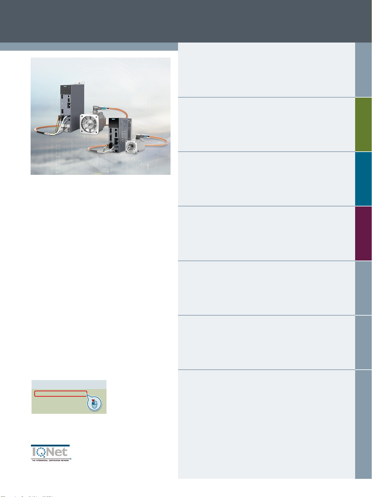
provides a comprehensive overview of the new SINAMICS S210 servo drive system consisting of a SINAMICS S210 servo converter,
a SIMOTICS S-1FK2 servomotor and a matching One Cable Connection (OCC).
The single-axis AC/AC servo converter system stands out due to its high performance and dynamic response for mid-range Motion
Control applications. In addition to details of updates and technical modifications, the latest edition of the catalog has also been
supplemented with the 400 V versions.
The products listed in this catalog are also included in the Industry Mall. Please contact your local Siemens office for additional
information.
NEW:
By clicking on the Article No. in the web PDF you can jump directly to the Industry Mall where you can obtain additional
information and order products online.
Up-to-date information about SINAMICS S210 is available on the Internet at:
www.siemens.com/sinamics-s210
You can access our Interactive Catalog and Industry Mall online at:
www.siemens.com/industrymall
Your personal contact will be happy to receive your suggestions and recommendations for improvement.
You can find your representative in our Personal Contact database at:
www.siemens.com/automation-contact
We hope that you will often enjoy using Catalog D 32 · January 2020 as a selection and ordering reference document and wish you
every success with our products and solutions.
With kind regards,
Achim Peltz
Vice President
General Motion Control
Siemens AG, Digital Industries, Motion Control
siemens.com/drives
Page 4

© Siemens 2020
Page 5
© Siemens 2020
SINAMICS S210 Servo Drive System
Motion Control Drives
Catalog D 32 · January 2020
Supersedes:
Catalog D 32 · April 2019
Refer to the Industry Mall for current updates of
this catalog:
www.siemens.com/industrymall
System overview
SINAMICS S210 servo drive
SIMOTICS S-1FK2 servomotors
MOTION-CONNECT connection systems
1
2
3
4
The products contained in this catalog can also be found
in the Interactive Catalog CA 01.
The Catalog CA 01 can be downloaded at:
www.siemens.com/automation/ca01
Please contact your local Siemens branch.
© Siemens 2020
Click on an Article No. in the catalog PDF to call it up in the
Industry Mall and to obtain all the information.
Article No.
6SL3070-0AA00-0AG0
6SL3072-0AA00-0AG0
Or directly on the Internet, e.g.
www.siemens.com/product?6SL3070-0AA00-0AG0
Engineering tools
Services and documentation
Appendix
5
6
7
The products and systems described in
this catalog are manufactured/distributed
under application of a certified quality
management system in accordance with
DIN EN ISO 9001. The certificate is
recognized by all IQNet countries.
Page 6

© Siemens 2020
Digital Enterprise
The building blocks that ensure
everything works together
perfectly in the digital enterprise
Digitalization is already changing all areas of life and existing
business models. It is placing greater pressure on industry
while at the same time creating new business opportunities.
Today, thanks to scalable solutions from Siemens, companies
can already become a digital enterprise and ensure their
competitiveness.
Industry faces tremendous challenges
Reduce
time-to-market
Today manufacturers
have to bring products to
market at an ever-increasing pace despite the
growing complexity of
these products. In the
past, a major manufacturer would push aside a
small one, but now it is a
fast manufacturer that
overtakes a slow one.
Boost
flexibility
Consumers want customized products, but at
a price they would pay
for a mass-produced
item. That only works
if production is more
flexible than ever
before.
Improve
quality
To ensure a high level of
quality while meeting
legal requirements,
companies have to
establish closed quality
loops and enable the
traceability of products.
Boost
efficiency
Today the product itself
needs to be sustainable
and environmentally
friendly, while energy
efficiency in production
has become a competitive advantage.
Increase
security
Increasing networking
escalates the threat to
production facilities
of cyberattacks. Today
more than ever, companies need suitable
security measures.
2
Siemens D 32 · January 2020
Page 7

© Siemens 2020
The digital enterprise has already
become a reality
To fully benefit from all the advantages of
digitalization, companies first have to
achieve complete consistency of their data.
Fully digitally integrated business processes,
including those of suppliers, can help to
create a digital representation of the entire
value chain. This requires
• the integration of industrial software
and automation,
• expansion of the communication networks,
• security in automation,
• and the use of business-specific
industrial services.
MindSphere
The cloud-based open IoT operating
system from Siemens
With MindSphere, Siemens offers a costeffective and scalable cloud platform as a
service (PaaS) for the development of applications. The platform, designed as an open
operating system for the Internet of Things,
makes it possible to improve the efficiency
of plants by collecting and analyzing large
volumes of production data.
Totally Integrated Automation (TIA)
Where digitalization becomes reality
Totally Integrated Automation (TIA) ensures
the seamless transition from the virtual to
the real world. It already encompasses all
the necessary conditions for transforming
the benefits of digitalization into true added
value. The data that will form the digital
twin for actual production is generated from
a common base.
IA/DT Digital Enterprise En 05.03.18
Digital Plant
Learn more about the
digital enterprise for the
process industry
www.siemens.com/
digitalplant
Digital Enterprise Suite
Learn more about the
digital enterprise for the
discrete industry
www.siemens.com/
digital-enterprise-suite
Siemens D 32 · January 2020
3
Page 8
With TIA Portal you can
cut your engineering time
by up to
30 %
© Siemens 2020
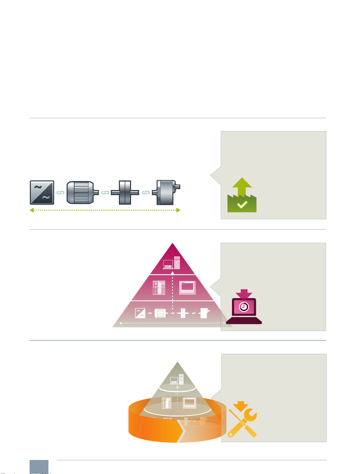
Integrated Drive Systems
Faster on the market and in the black with Integrated Drive Systems
Integrated Drive Systems are Siemens’ trendsetting answer to the high
degree of complexity that characterizes drive and automation technology
today. The world’s only true one-stop solution for entire drive systems is
characterized in particular by its threefold integration: Horizontal, vertical,
and lifecycle integration ensure that every drive system component fits
seamlessly into the whole system, into any automation environment, and
even into the entire lifecycle of a plant.
Horizontal integration
Integrated drive portfolio: The core elements of a fully integrated drive
portfolio are frequency converters, motors, couplings, and gear units.
At Siemens, they‘re all available from a single source. Perfectly integrated,
perfectly interacting. For all power and performance classes. As standard
solutions or fully customized. No other player in the market can offer a
comparable portfolio. Moreover, all Siemens drive components are
perfectly matched, so they are optimally interacting.
The outcome is an optimal workflow – from engineering all the way to
service that entails more productivity, increased efficiency, and better
availability. That’s how Integrated Drive Systems reduce time to market
and time to profit.
You can boost the avail ability
of your application or plant
to up to
*
99 %
*e.g., conveyor application
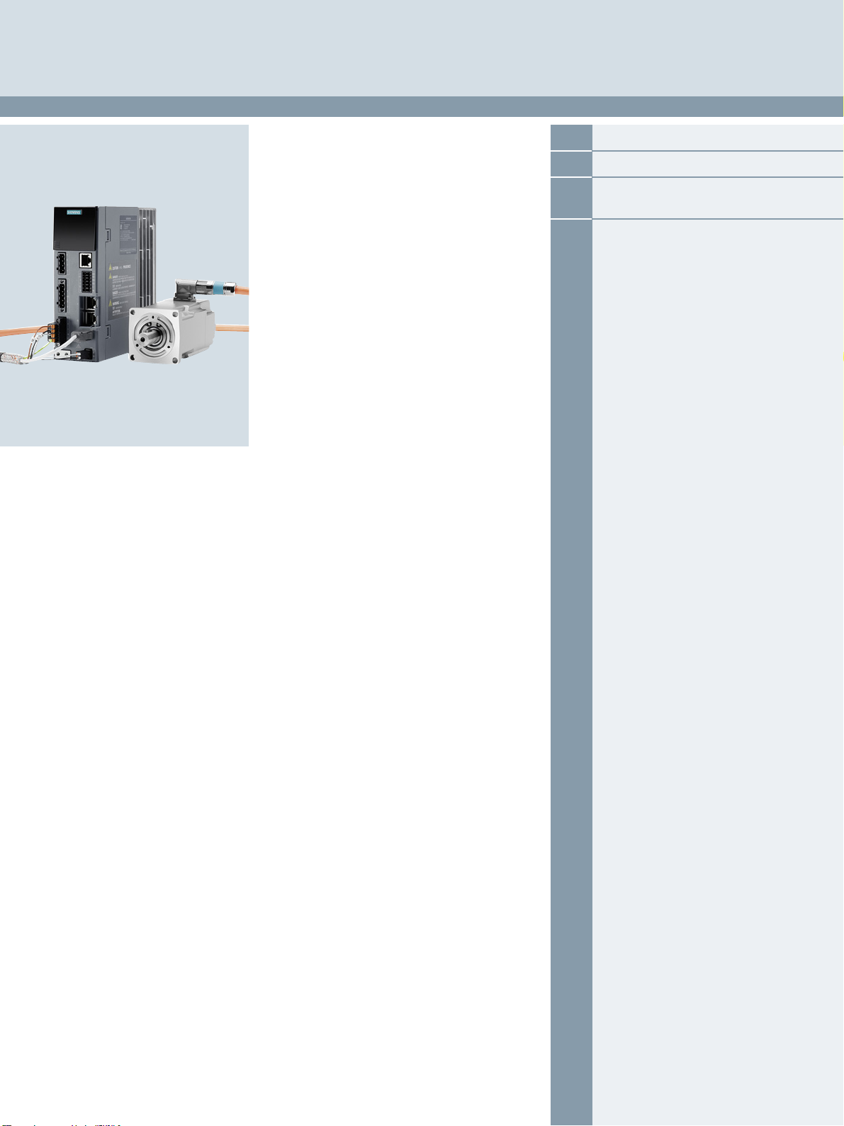
Vertical integration
Thanks to vertical integration, the complete drive train is
seamlessly integrated in the entire automation environment –
an important prerequisite for production with maximum
value added. Integrated Drive Systems are part of Totally
Integrated Automation (TIA), which means that they
are perfectly embedded into the system architecture
of the entire industrial production process. This
enables optimal processes through maximum
communication and control.
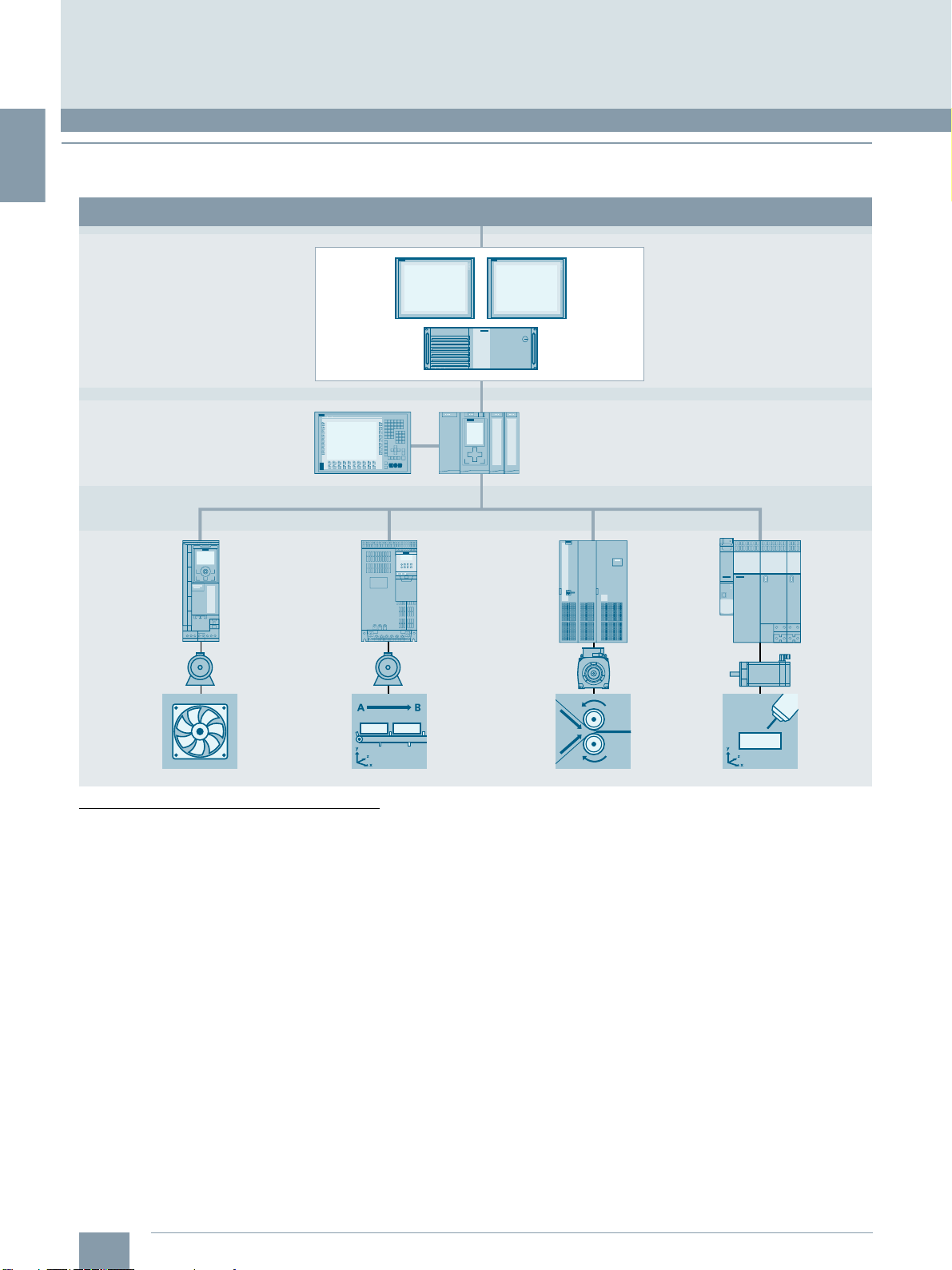
Lifecycle integration
Lifecycle integration adds the factor of time: Software and service
are available for the entire lifecycle of an Integrated Drive System.
That way, important optimization potential for maximum
productivity, increased efficiency, and highest availability
can be leveraged throughout the system’s lifecycle –
from planning, design, and engineering to operation,
maintenance, and all the way even to
modernization.
With Integrated Drive Systems, assets
become important success factors. They
ensure shorter time to market, maximum
productivity and efficiency in operation,
and shorter time to profit.
With Integrated Drive
Systems you can reduce
your main tenance costs
by up to
15 %
4
Siemens D 32 · January 2020
www.siemens.com/ids
Page 9
System overview
© Siemens 2020
1
1/2 The SINAMICS converter family
1/6 Drive selection
1/7 SINAMICS S210 servo drive system
1/13 Order overview
1/20 SINAMICS S210 starter kit
Siemens D 32 · January 2020
Page 10
1
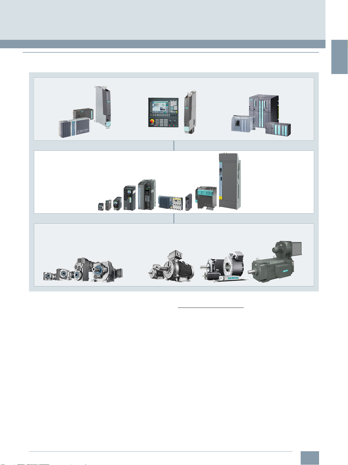
System overview
Management level
Process control level Control center / control system:
SIMATIC PCS 7 / WINCC
Automation systems / HMI:
SIMATIC / SIMOTION / SINUMERIK
pumping
ventilating
compressing
moving processing
machining
G_D011_EN_00337d
Office environment: SIMATIC IT / COMOS...
Control level
Fieldbus
SINAMICS V
SINAMICS G
SINAMICS V
SINAMICS G
SINAMICS S
SINAMICS V
SINAMICS G
SINAMICS S
SINAMICS S
The SINAMICS converter family
■
Overview
Integration in automation
© Siemens 2020
Totally Integrated Automation and communication
SINAMICS is an integral component of the Siemens "Totally
Integrated Automation" concept. Integrated SINAMICS systems
covering configuration, data storage, and communication at
automation level ensure low-maintenance solutions with the
SIMATIC, SIMOTION and SINUMERIK control systems.
Depending on the application, the appropriate variable
frequency drives can be selected and incorporated in the automation concept. With this in mind, the drives are clearly subdivided into their different applications. A wide range of communication options (depending on the drive type) are available for
establishing a communication link to the automation system:
•PROFINET
Applications
SINAMICS is the comprehensive converter family from Siemens
designed for machine and plant engineering applications.
SINAMICS offers solutions for all drive tasks:
• Simple pump and fan applications in the process industry
• Demanding single drives in centrifuges, presses, extruders,
elevators, as well as conveyor and transport systems
• Drive line-ups in textile, plastic film, and paper machines as
well as in rolling mill plants
• Highly dynamic servo drives for machine tools, as well as
packaging and printing machines
• PROFIBUS
• EtherNet/IP
• Modbus TCP
•Modbus RTU
•BACnet MS/TP
• AS-Interface
1/2
Siemens D 32 · January 2020
Page 11
1
■
SIMOTICSSIMOGEAR
G_D011_XX_00515b
SIMATICSIMOTION SINUMERIK
SINAMICS
Overview
SINAMICS as part of the Siemens modular automation system
© Siemens 2020
System overview
The SINAMICS converter family
Innovative, energy-efficient and reliable drive systems and
applications as well as services for the entire drive train
The solutions for drive technology place great emphasis on
the highest productivity, energy efficiency and reliability for all
torque ranges, performance and voltage classes.
Siemens offers not only the right innovative variable frequency
drive for every drive application, but also a wide range of
energy-efficient low-voltage motors, geared motors, explosionprotected motors and high-voltage motors for combination with
SINAMICS.
Furthermore, Siemens supports its customers with global
pre-sales and after-sales services, with over 295 service points
in 130 countries – and with special services e.g. application
consulting or motion control solutions.
Energy efficiency
Energy management process
Efficient energy management consultancy identifies the energy
flows, determines the potential for making savings and implements them with focused activities.
Almost two thirds of the industrial power requirement is from
electric motors. This makes it all the more important to use drive
technology permitting energy consumption to be reduced effectively even in the configuration phase, and consequently to
optimize plant availability and process stability. With SINAMICS,
Siemens offers powerful energy efficient solutions which,
depending on the application, enable a significant reduction in
electricity costs.
Siemens D 32 · January 2020
1/3
Page 12
1
SINAMICS V drives focus on
the essentials both in terms of hardware
and functionality.
This results in a high degree of ruggedness
combined with lower investment costs.
SINAMICS G drives function perfectly for low
and medium demands on the dynamic
response of the control system.
SINAMICS S drives are predestined
for demanding single - and multi-axis
applications in machine and plant engineering
as well as for numerous motion control tasks.
Price
G_D011_EN_00449b
Performance
SINAMICS SSINAMICS GSINAMICS V
© Siemens 2020
System overview
The SINAMICS converter family
■
Overview
Up to 70 % potential for savings using variable-speed operation
SINAMICS enables great potential for savings to be realized by
controlling the motor speed. In particular, huge potential savings
can be recovered from pumps, fans and compressors which are
operated with mechanical throttle and valves. Here, changing to
variable-speed drives brings enormous economic advantages.
In contrast to mechanical control systems, the power consumption at partial load operation is always immediately adjusted to
the demand at that time. So energy is no longer wasted,
permitting savings of up to 60 % – in exceptional cases even up
to 70 %. Variable-speed drives also offer clear advantages over
mechanical control systems when it comes to maintenance and
repair. Current spikes when starting up the motor and strong
torque surges become things of the past – and the same goes
for pressure waves in pipelines, cavitation or vibrations which
cause sustainable damage to the plant. Smooth starting and
ramp-down relieve the load on the mechanical system, ensuring
a significantly longer service life of the entire drive train.
Varia nts
Depending on the application, the SINAMICS converter family offers the ideal variant for any drive task.
Regenerative feedback of braking energy
In conventional drive systems, the energy produced during
braking is converted to heat using braking resistors. Energy
produced during braking is efficiently recovered to the supply
system by versions of SINAMICS G and SINAMICS S drives with
regenerative feedback capability and these devices do not
therefore need a braking resistor. This permits up to 60 % of the
energy requirement to be saved, e.g. in lifting applications.
Energy which can be reused at other locations on a machine.
Furthermore, this reduced power loss simplifies the cooling of
the system, enabling a more compact design.
Energy transparency in all configuration phases
Early on, in the configuration phase, the SIZER for Siemens
Drives engineering tool provides information on the specific
energy requirement. The energy consumption across the entire
drive train is visualized and compared with different plant
concepts.
SINAMICS in combination with energy-saving motors
Engineering integration stretches beyond the SINAMICS
converter family to higher-level automation systems, and to a
broad spectrum of energy-efficient motors with a wide range of
performance classes, which, compared to previous motors, are
able to demonstrate up to 10 % greater efficiency.
1/4
Siemens D 32 · January 2020
Page 13
1
■
Engineering tools (e.g. Drive Technology Configu rato r, SIZER for Siemens Drives, STARTER and SINAMICS Startdrive)
G_D011_EN_00450o
Pumps, fans,
compressors,
conveyor
belts, mixers,
mills, spinning
machines,
textile
machines,
refrigerated
display
counters,
fitness
equipment,
ventilation
systems,
single-axis
positioning
applications in
machine and
plant
engineering
Handling
machines,
packaging
machines,
automatic
assembly
machines,
metal forming
machines,
printing
machines,
winding and
unwinding
units
0.12 kW to
250 kW
0.05 kW to
7 kW
Conveyor
technology,
single-axis
positioning
applications
(G120D)
Pumps,
fans,
compressors,
building
management
systems,
process
industry,
HVAC,
water/waste
water
industries
0.37 kW to
7.5 kW
0.75 kW to
630 kW
D 31.5
Catalog
D 31.1
Catalog
D 33
CatalogCatalog
D 31.2
Pumps,
fans,
compressors,
conveyor
belts,
extruders,
mixers, mills,
kneaders,
centrifuges,
separators
Pumps,
fans,
compressors,
conveyor
belts, mixers,
mills,
extruders
2.2 kW to
6600 kW
75 kW to
2700 kW
Catalog Catalog
D 11
D 18.1
Single-axis
positioning
applications in
machine and
plant
engineering
0.55 kW to
132 kW
Catalog Catalog
D 31.1 D 32
0.55
kW to
5700 kW
0.05 kW to
7 kW
Catalogs
D 21.3, D 21.4
NC 62
Test bays,
cross cutters,
centrifuges
75 kW to
1200 kW
Catalog
D 21.3
Rolling mill
drives,
wire-drawing
machines,
extruders and
kneaders,
cableways
and lifts,
test bay drives
6 kW to
30 MW
Catalog
D 23.1
* Industry Mall
0.15 MW to
85 MW
Catalogs
D 15.1, D 12
Converters for
applications
with high
outputs
High performance
frequency converters
Industry-specific frequency
converters
Distributed
frequency
converters
Standard performance
frequency converters
Servo drives
Medium
voltage
Low voltage
Packaging
machines,
handling
equipment,
feed and
withdrawal
devices,
stacking units,
automatic
assembly
machines,
laboratory
automation,
wood, glass
and ceramics
industry,
digital printing
machines
Production
machines
(packaging,
textil e and
printing
machines,
paper
machines,
plastic
processing
machines),
machine
tools, plants,
process lines
and rolling
mills, marine
drives, test
bays
Pumps,
fans,
compressors,
mixers,
extruders,
mills,
crushers,
rolling mills,
conveyor
technology,
excavator s,
test bays,
marine drives,
blast furnace
fans, retrofit
DC
converters
Direct
voltage
* DC/DC
controllers
GH150
GH180
GM150
SM150
GL150
SL150
SM120CM
V20
G120C
G120
SINAMICS SINAMICSSINAMICSSINAMICS
SIMATIC
ET 200pro FC-2
SINAMICS SINAMICS SINAMICS SINAMICS SINAMICS SINAMICS SINAMICS
V90G110D
G120D
G110M
G180
G130
G150
S110
SINAMICS
S210 S120
S120M
S150 DCM
DCP *
G120X
Overview
Platform concept
All SINAMICS variants are based on a platform concept. Joint
hardware and software components, as well as standardized
tools for dimensioning, configuration, and commissioning tasks
ensure high-level integration across all components. SINAMICS
handles a wide variety of drive tasks with no system gaps. The
different SINAMICS variants can be easily combined with each
other.
Quality management according to EN ISO 9001
SINAMICS conforms to the most exacting quality requirements.
Comprehensive quality assurance measures in all development
and production processes ensure a consistently high level of
quality.
Of course, our quality management system is certified by an
independent authority in accordance with EN ISO 9001.
© Siemens 2020
System overview
The SINAMICS converter family
IDS – Integration at its very best
The Siemens Integrated Drive Systems (IDS) solution offers
perfectly matched drive components with which you can meet
your requirements. The drive components reveal their true
strengths as an Integrated Drive System over the full range
from engineering and commissioning through to operation:
Integrated system configuration is performed using the Drive
Technology Configurator: Just select a motor and a converter
and design them with the SIZER for Siemens Drives engineering
tool. The STARTER and SINAMICS Startdrive commissioning
tools integrate the motor data and at the same time simplify
efficient commissioning. Integrated Drive Systems are incorporated in the TIA Portal – this simplifies engineering, commissioning and diagnostics.
Siemens D 32 · January 2020
1/5
Page 14

1
1)
Industry-specific converters.
2)
Information on the SIMATIC ET 200pro FC-2 frequency converter is
available in Catalog D 31.2 and at: www.siemens.com/et200pro-fc
© Siemens 2020
System overview
Drive selection
■
Overview
SINAMICS selection guide – typical applications
Use Requirements for torque accuracy/speed accuracy/position accuracy/coordination of axes/functionality
Continuous motion Non-continuous motion
Basic Medium High Basic Medium High
Pumping,
ventilating,
compressing
Moving Conveyor belts
Processing Mills
Machining Main drives for
Centrifugal pumps
Radial / axial fans
Compressors
V20
G120C
G120X
Roller conveyors
Chain conveyors
V20
G110D
G110M
G120C
ET 200pro FC-2
Mixers
Kneaders
Crushers
Agitators
Centrifuges
V20
G120C
• Turning
• Milling
• Drilling
S110 S110
Centrifugal pumps
Radial / axial fans
Compressors
G120X
G130/G150
G180
Conveyor belts
Roller conveyors
Chain conveyors
Lifting/lowering
devices
Elevators
Escalators/moving
walkways
Indoor cranes
Marine drives
Cable railways
G120
G120D
G130/G150
G180
2)
Mills
Mixers
Kneaders
Crushers
Agitators
Centrifuges
Extruders
Rotary furnaces
G120
G130/G150
G180
Main drives for
• Drilling
• Sawing
S120
Eccentric screw
pumps
S120 G120 S110 S120
1)
Elevators
Container cranes
Mining hoists
Excavators for
open-cast mining
Test bays
S120
S150
1)
1)
DCM
Extruders
Winders/unwinders
Lead/follower drives
Calenders
Main press drives
Printing machines
S120
S150
DCM
Main drives for
• Turning
• Milling
• Drilling
• Gear cutting
•Grinding
S120 S110 S110
Using the SINAMICS selection guide
The varying range of demands on modern variable frequency
drives requires a large number of different types. Selecting the
optimum drive has become a significantly more complex process. The application matrix shown simplifies this selection process considerably, by suggesting the ideal SINAMICS drive for
examples of typical applications and requirements.
Hydraulic pumps
Metering pumps
Acceleration
conveyors
Storage and retrieval
machines
V90
G120
G120D
Tubular bagging
machines
Single-axis motion
control
such as
• Position profiles
• Path profiles
V90
G120
Axis drives for
• Turning
• Milling
• Drilling
Hydraulic pumps
Metering pumps
Acceleration
conveyors
Storage and retrieval
machines
Cross cutters
Reel changers
S110
S210
DCM
Tubular bagging
machines
Single-axis motion
control
such as
• Position profiles
• Path profiles
S110
S210
Axis drives for
• Drilling
• Sawing
S120
Descaling pumps
Hydraulic pumps
Storage and retrieval
machines
Robotics
Pick & place
Rotary indexing tables
Cross cutters
Roll feeds
Engagers/disengagers
S120
S210
DCM
Servo presses
Rolling mill drives
Multi-axis motion
control
such as
• Multi-axis positioning
•Cams
• Interpolations
S120
S210
DCM
Axis drives for
• Turning
• Milling
• Drilling
• Lasering
• Gear cutting
•Grinding
• Nibbling and
punching
S120
• The application type is selected from the vertical column
- Pumping, ventilating, compressing
-Moving
- Processing
- Machining
• The quality of the motion type is selected from the horizontal row
-Basic
-Medium
-High
■
More Information
Further information about SINAMICS is available on the
Internet at
www.siemens.com/sinamics
1/6
Siemens D 32 · January 2020
Practical application examples and descriptions are available
on the Internet at
www.siemens.com/sinamics-applications
Page 15
1
■
Overview
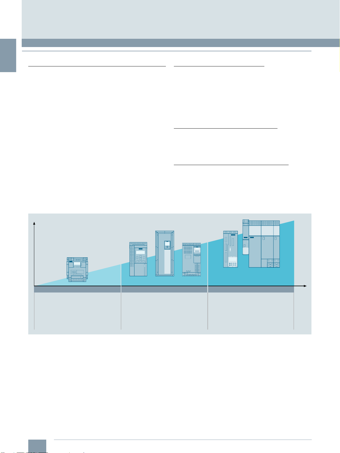
Example: SINAMICS S210 converter frame size FSB, 200 V 1 AC,
with SIMOTICS S-1FK2 servomotor shaft height 30
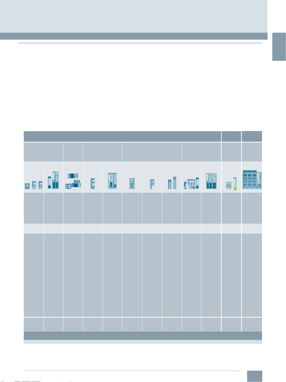
Example: SINAMICS S210 converter frame size FSB, 400 V 3 AC,
with SIMOTICS S-1FK2 servomotor shaft height 63
The new servo drive system comprises a SINAMICS S210 servo
converter, a SIMOTICS S-1FK2 servomotor and a matching
One Cable Connection (OCC) for connecting the motor to the
converter. The SINAMICS S210 is a single-axis AC/AC servo
converter system with high performance and dynamic response
for mid-range Motion Control applications.
SINAMICS S210 servo converters are available for the following
line voltages:
• 200 V to 240 V 1 AC (1 AC series)
• 200 V to 480 V 3 AC (3 AC series)
Depending on the converter voltage, the SIMOTICS S-1FK2
servomotors are available in the following frame sizes and
torque ranges:
•1AC series
- Up to 240 V: Shaft heights 20 to 48 with 0.16 to 3.6 Nm
•3AC series
- Up to 240 V: Shaft heights 20 to 100 with 0.16 to 40 Nm
- Up to 480 V: Shaft heights 40 to 100 with 1.27 to 40 Nm
The motors are available in the High Dynamic (HD) and
Compact (CT) designs.
© Siemens 2020
System overview
SINAMICS S210 servo drive system
The SINAMICS S210 can be used in numerous applications.
Typical applications are:
• Packaging machines
• Handling equipment
• Feed and withdrawal devices
• Stacking units
• Automatic assembly machines
• Laboratory automation
• Woodworking, glass and ceramic industries
• Digital printing machines
Flexible in application
The SINAMICS S210 is a flexible, versatile system.
SIMOTICS S-1FK2 series synchronous servomotors are installed
in rotary and linear axes. The integrated One Cable Connection
(OCC) interface allows user-friendly connection of a
SIMOTICS S-1FK2 motor with just one cable. The electronic
motor type plate data can be read out, which eliminates the need
to parameterize the converter with the motor data. This significantly simplifies and shortens commissioning.
In conjunction with the technological functions of the higher-level
controller, there are many possibilities of motion – from continuous operation through positioning and synchronous operation,
to coordinated motion of multiple axes via cyclic cams or
interpolation – everything is possible.
The SINAMICS S210 converter has an integrated PROFINET
communications interface for connecting to a control system.
The data exchange with the higher-level controllers takes place
via standardized protocols – the PROFIdrive profile for positioning mode and the PROFIsafe profile for safety-related communication.
Thus, operation is optimally ensured with the SIMATIC S7
automation system. The drive axis is connected via technology
objects and Motion Control blocks in the SIMATIC S7 or a
SIMOTION controller.
High performance for fast and precise control
The high performance of the SINAMICS S210 servo drive
system in conjunction with the SIMOTICS S-1FK2 servomotor
derives from the following features:
• Low moment of inertia and high overload capability of the
motor
• High-resolution encoder with fast scanning
• Current controller clock cycle of 62.5 μs and a pulse
frequency of 8 kHz of the servo converter
This enables short cycle times on the machine even with
complex motion control.
DC link coupling (only 3 AC series)
For devices of the 3 AC series, the DC links of up to six converters can be coupled. Thus, energy balancing between the axes
is possible and energy produced during braking can be used by
other axes for accelerating. This is not only efficient but also
reduces the dissipated heat in the control cabinet, because the
energy that is produced no longer has to be converted to heat in
the braking resistor.
Siemens D 32 · January 2020
1/7
Page 16
1
System overview
SINAMICS S210 servo drive system
■
Overview
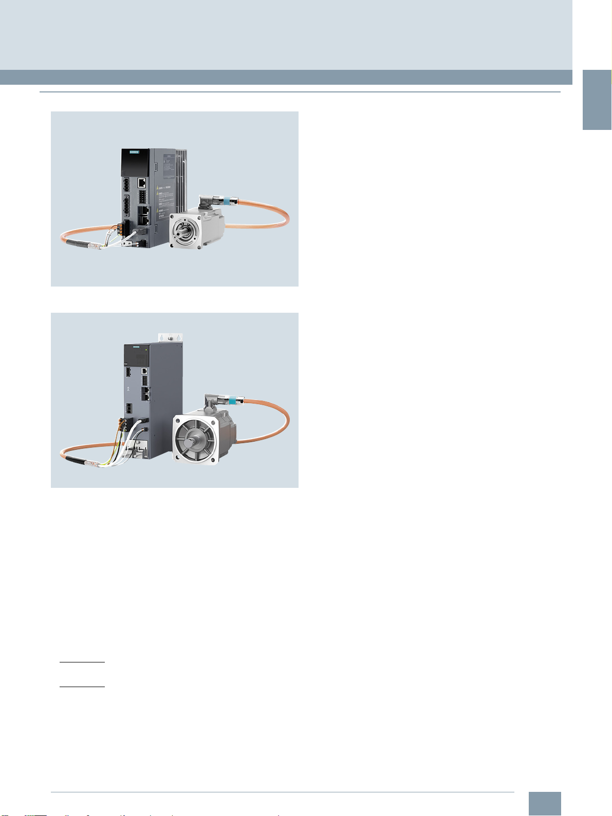
Optimized connection technology with
One Cable Connection (OCC)
© Siemens 2020
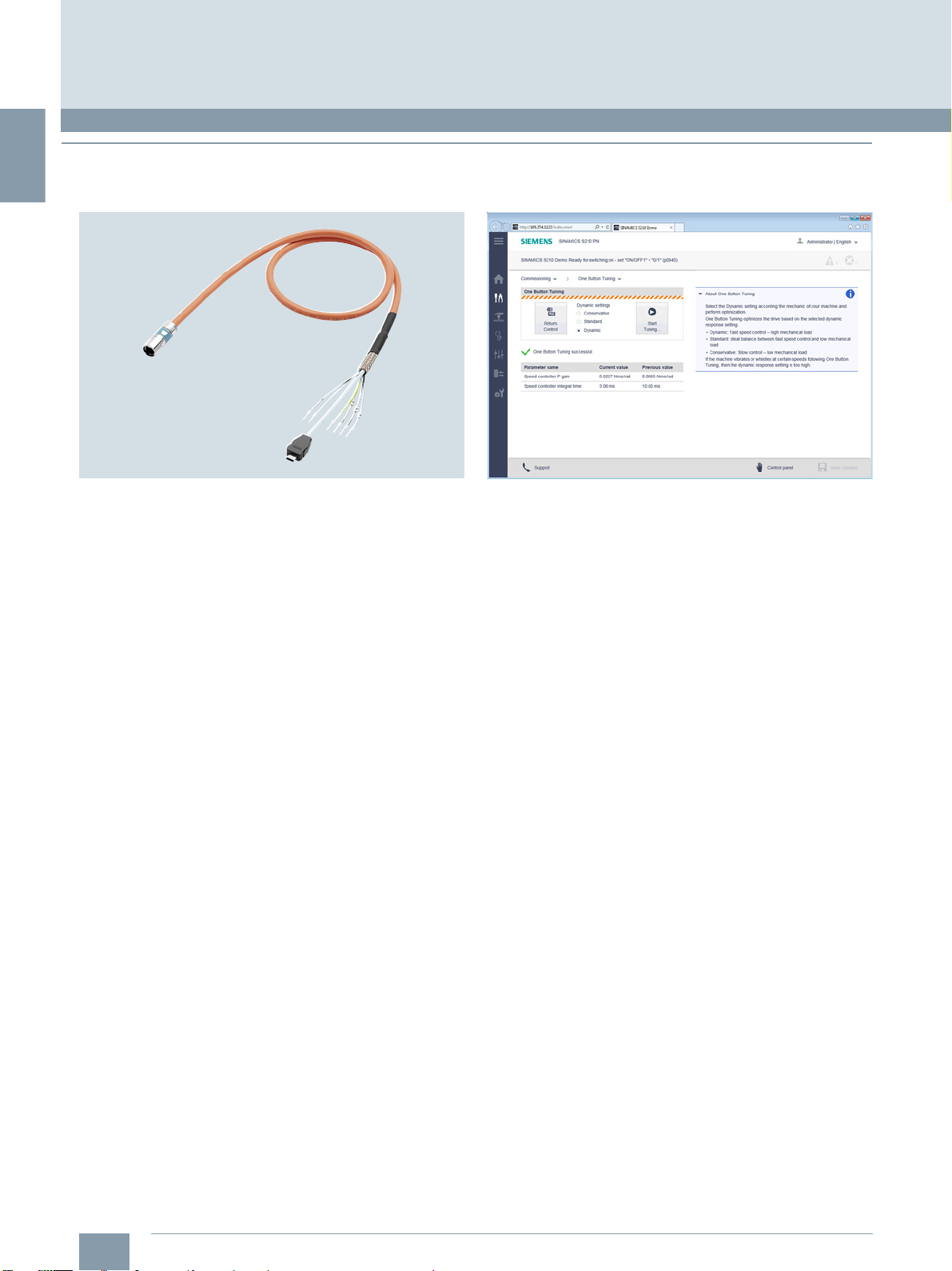
Easy commissioning via web server, One Button Tuning and
SINAMICS Startdrive/TIA Portal (V15.1 or higher)
Example: SINAMICS S210 M12 OCC connecting cable
Motor and converter are simply connected to one another by
one instead of the usual two or three cables. With this One Cable
Technology, energy supply, encoder signals and braking signal
are brought together in a single cable. This results in the following advantages:
• Time-saving by laying only one cable
• Smaller installation space and space requirement in cable
collars, tight bending radii
• Only one cable has to be cleaned. This is advantageous, e.g.
in the pharmaceutical industry and where higher requirements
are placed upon hygiene
• Can be ordered to the decimeter
• Compact connection system
• Rotatable connector on the motor side
• Motor with very low interfering contour for restricted installation space.
Cables are available in two different qualities:
• MOTION-CONNECT 500
• MOTION-CONNECT 800PLUS
In addition to the pre-assembled cable, individual components
(connectors and products sold by the meter) can be ordered for
self-assembly (available soon).
One Button Tuning
The web server of the converter offers a simple means of
parameter assignment. The web server allows commissioning
purely oriented on the functionality of the drive. With the web
server, the SINAMICS S210 servo drive system can be brought
into operation with a few clicks.
As a result of reading the electronic type plate of the connected
SIMOTICS S-1FK2 servomotor, only a few operator actions, such
as automatic controller optimization with One Button Tuning,
are necessary, as the motor and encoder are automatically
detected. The controller parameters are automatically optimized. The three selectable dynamic levels of the controller can
optimally take into account the desired behavior of the
connected mechanics.
A motion of the axis can take place directly via the control panel
during commissioning.
The customer benefits from the web server in many ways:
• Commissioning can also be easily done in places difficult to
access, as the web server in the converter can also be
accessed directly via PROFINET from the controller.
• The web server provides full diagnostic capability without the
need for additional software.
• Commissioning and diagnostics can also be done without a
cable via mobile devices, such as laptops, smart phones and
tablets (an additional WLAN access point is necessary).
• Intuitive user interface
In addition to easy commissioning directly via the web server
of the converter, engineering is also possible with SINAMICS
Startdrive and TIA Portal (V15.1 or higher). The tool for configuration, commissioning and diagnostics has been optimized with
regard to the consistent utilization of the TIA Portal advantages –
one shared work environment for PLC, HMI and drives.
SINAMICS firmware V5.2 or higher is required for
SINAMICS S210 devices.
For more information, see the Engineering tools section.
1/8
Siemens D 32 · January 2020
Page 17

1
■
1)
Available in SINAMICS V5.1 SP1 and higher. The Extended Functions
require a Safety license.
Overview
Diagnostics
Faults and warnings are shown on the display located under the
front cover, and they can be acknowledged with the Acknowledge button. Extensive diagnostics with plain text messages for
cause and remedy information is possible via the web server.
Safety Integrated
The integrated safety functions provide highly effective, application-oriented protection for personnel and machinery (terms as
defined in IEC 61800-5-2).
The following Safety Integrated Basic Functions are included as
standard:
• Safe Torque Off (STO)
• Safe Brake Control (SBC)
• Safe Stop 1 (SS1)
The following Safety Integrated Extended Functions
available as options:
• Safe Stop 2 (SS2)
• Safe Operating Stop (SOS)
• Safely-Limited Speed (SLS)
• Safe Speed Monitor (SSM)
• Safe Direction (SDI)
• Safely-Limited Acceleration (SLA)
• Safe Brake Test (SBT) diagnostic function
The Safety Integrated Functions are fully integrated into the drive
system. They can be activated via fail-safe digital inputs on the
converter (only STO and SS1) or via PROFINET with PROFIsafe.
The Safety Integrated Functions are implemented electronically
and therefore require no additional installation effort or space in
the control cabinet. Furthermore, the costs are considerably
lower than for externally implemented monitoring functions.
The Safety Integrated Functions can be easily commissioned
using the web server of the converter or SINAMICS Startdrive/
TIA Portal V15.1 or higher.
1)
are
© Siemens 2020
System overview
SINAMICS S210 servo drive system
Perfect combination with
SIMATIC S7-1500, SIMATIC S7-1500 T-CPU,
SIMATIC ET 200SP Open Controller, and PROFINET
It communicates with the higher-level control via PROFINET IRT.
For optimal interaction between the controller and the
SINAMICS S210 servo drive system, SIMATIC S7-1500,
SIMATIC S7-1500 T-CPU, SIMATIC ET 200SP Open Controller,
and SIMOTION can be used as the control system.
The SINAMICS S210 servo converter has an integrated
PROFINET communications interface with a cycle of up to
250 μs for connecting to a control system.
Standardized protocols for linking to a higher-level control with
RT and IRT are supported – the PROFIdrive profile with DSC for
positioning mode and the PROFIsafe profile for safety-related
communication. Functions, such as Shared Device, ring redundancy and PROFIenergy, are also possible.
Everything from one source: Through the use of Motion Control
functionalities in the controller, the combination of converter and
SIMATIC S7 automation system or a SIMOTION controller allows
ideally harmonized engineering. As a result, commissioning
times are shortened.
Via technology objects and Motion Control blocks of the higherlevel controller, there are many possibilities of motion, such as
continuous operation, positioning and synchronous operation,
and coordinated motion of multiple axes via cyclic cams or
interpolation.
Siemens offers tested SIMATIC PLC/HMI application examples
for connection of the servo drive system to a SIMATIC controller:
www.siemens.com/sinamics-applications
Further information on the SIMATIC S7-1500,
SIMATIC S7-1500 T-CPU and SIMATIC ET 200SP Open Controller is available in the ST 70 Catalog and on the Internet under
www.siemens.com/simatic-s7-1500
Change 07/2020
Siemens D 32 · January 2020
1/9
Page 18
1
System overview
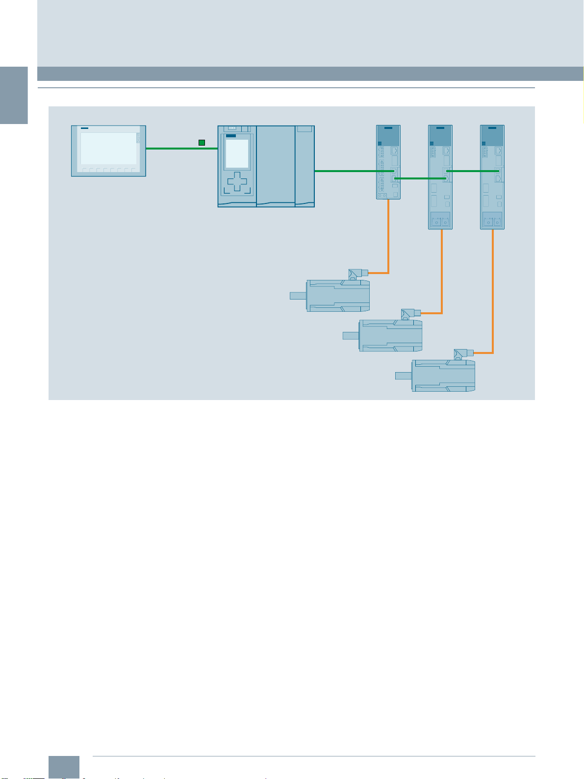
OCC (One Cable Connection for motor,
motor holding brake and encoder)
SIMOTICS S-1FK2 servomotors
G_D211_EN_00392
SINAMICS S210 servo driveSIMATIC S7-1515T PN SIMATIC Basic Panel
PROFINET IRT
PROFINET
SINAMICS S210 servo drive system
■
Overview
© Siemens 2020
Example: Communication via PROFINET
Ruggedness
The SINAMICS S210 is equipped as standard with varnished or
partially varnished modules. The painting on the modules protects the sensitive SMD components against corrosive gases,
chemically active dust and moisture.
Can be used worldwide
In addition to the usual approvals, the SINAMICS S210 drive
system also has UL approval for the North American market.
This means that the drive system, comprising SINAMICS S210
and SIMOTICS S-1FK2, including the One Cable Connection
(OCC), can be used worldwide.
More information
A Quick Installation Guide is supplied in hard copy form in
English with every SINAMICS S210. Further documentation,
such as the operating instructions, is available free on the
Internet at:
www.siemens.com/sinamics-s210/documentation
Detailed information on the SINAMICS S210 drive system,
including the latest technical documentation (brochures,
tutorials, dimensional drawings, certificates, manuals and
operating instructions), is available on the Internet at:
www.siemens.com/sinamics-s210
and is also available via the Drive Technology Configurator
(DT Configurator) on the Internet.
The DT Configurator can be found in the Siemens Industry Mall
at the following address:
www.siemens.com/dt-configurator
1/10
Siemens D 32 · January 2020
Page 19
1
■
Overview
© Siemens 2020
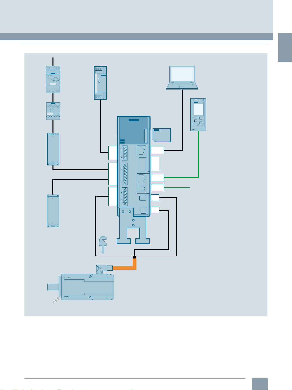
System overview
SINAMICS S210 servo drive system
Fuse or
circuit-breaker
Line contactor
(optional)
Line filter
(optional)
External
braking resistor
(optional)
Power supply
24 V DC
SINAMICS S210
converter
1 AC series
X124
X1
X2
SD memory card
(optional)
X127
F-DI
X130
measuring probe
X150 P1
X150 P2
X100
X107
Commissioning device
Controller
(e.g. SIMATIC S7-1500)
To further PROFINET devices
(e.g. further SINAMICS S210)
SIMOTICS S-1FK2
servomotor
Shaft sealing ring
(optional)
Example for the 1 AC series
Shield plate
Shield
connection clamp
OCC (One Cable Connection for motor,
motor holding brake and encoder)
G_D211_EN_00368a
Siemens D 32 · January 2020
1/11
Page 20
1
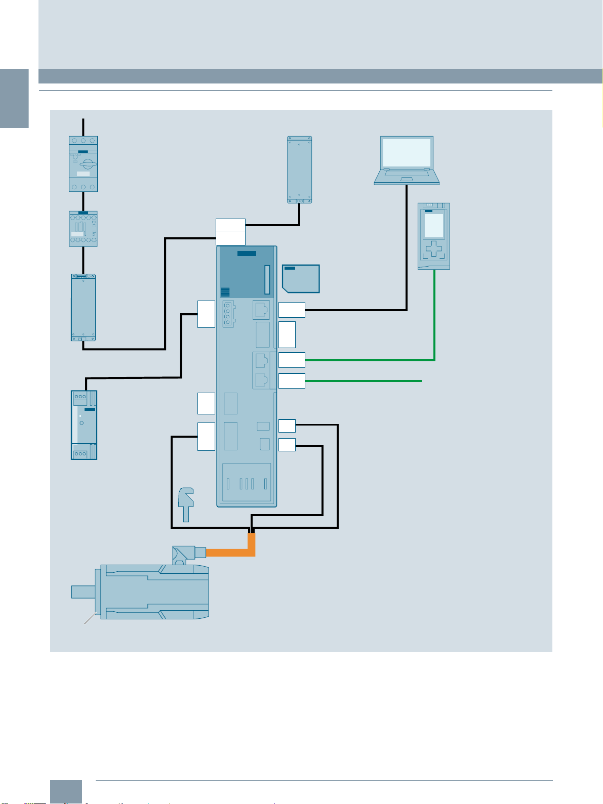
System overview
SINAMICS S210 servo drive system
■
Overview
© Siemens 2020
Fuse or
circuit-breaker
Line contactor
(optional)
Line filter
(optional)
DC link
coupling
(optional)
SINAMICS S210
converter
3 AC series
X4
X1
X124
X3
X2
External
braking resistor
(optional)
SD memory card
(optional)
X127
F-DI
X130
measuring probe
X150 P1
X150 P2
X100
X107
Commissioning device
Controller
(e.g. SIMATIC S7-1500)
To further PROFINET devices
(e.g. further SINAMICS S210)
Power supply
24 V DC
SIMOTICS S-1FK2
servomotor
Shaft sealing ring
(optional)
Example for the 3 AC series
Shield connection
clamp
OCC (One Cable Connection for motor,
motor holding brake and encoder)
G_D211_EN_00391
1/12
Siemens D 32 · January 2020
Page 21
1
Clicking to the Industry Mall
6SL3255-0AA00-5AA0
© Siemens 2020
System overview
SINAMICS S210 servo drive system
■
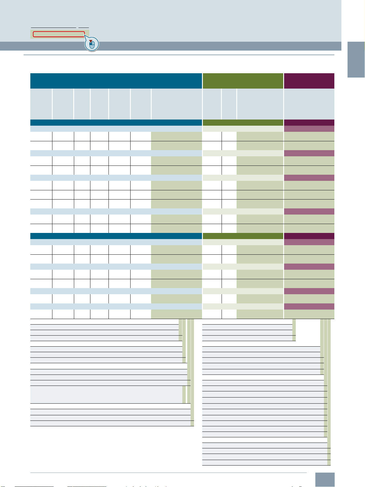
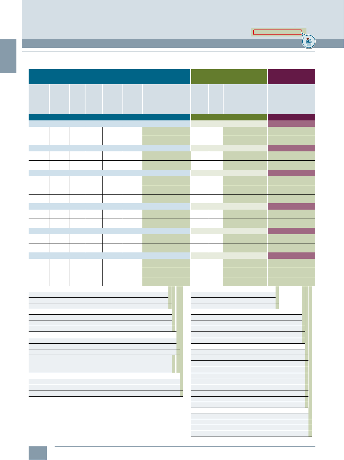
Order overview
SINAMICS S210 drive system for line connection 200 ... 240 V 1 AC
SIMOTICS S-1FK2 servomotor SINAMICS S210 servo converter
Static
torque
M
0
Nm
(lb
High Dynamic for highly dynamic applications SINAMICS S210 servo converter One Cable Connection
Shaft height 20 – rated speed n
0.16
(0.12)
0.32
(0.24)
Shaft height 30 – rated speed n
0.64
(0.47)
1.27
(0.94)
Shaft height 40 – rated speed n
1.27
(0.94)
2.4
(1.77)
3.2
(2.36)
Shaft height 40 – rated speed n
1.27
(0.94)
2.4
(1.77)
Compact for high precision applications SINAMICS S210 servo converter One Cable Connection
Shaft height 30 – rated speed n
0.64
(0.47)
1.27
(0.94)
Shaft height 40 – rated speed n
2.4
(1.77)
3.2
(2.36)
Shaft height 40 – rated speed n
2.4
(1.77)
Shaft height 48 – rated speed n
3.6
(2.66)
Article No. supplements
Holding brake Pre-assembled MOTION-CONNECT cable
Without brake 0 MOTION-CONNECT 500 5
With brake 1 MOTION-CONNECT 800PLUS 8
Maximum
torque
M
Nm
-ft)
(lb
f
0.56
(0.41)
1.11
(0.82)
1.95
(1.44)
4.05
(2.99)
3.75
(2.77)
7.5
(5.53)
10
(7.38)
3.85
(2.84)
7.6
(5.61)
1.85
(1.36)
3.75
(2.77)
7.1
(5.24)
9.5
(7.01)
7.1
(5.24)
10.8
(7.97)
max
-ft) rpm
f
Maxi-
Rated
power
230 V
kW
(hp)
rated
(0.07)
(0.13)
rated
(0.27)
(0.54)
rated
(0.27)
(0.51)
(0.67)
rated
(0.54)
(1.01)
rated
(0.27)
(0.54)
rated
(0.51)
(0.67)
rated
(1.01)
rated
(0.71)
Rated
torque
Nm
(lb
3000 rpm
0.16
(0.12)
0.32
(0.24)
3000 rpm
0.64
(0.47)
1.27
(0.94)
1500 rpm
1.27
(0.94)
2.4
(1.77)
3.2
(2.36)
3000 rpm
1.27
(0.94)
2.4
(1.77)
3000 rpm
0.64
(0.47)
1.27
(0.94)
1500 rpm
2.4
(1.77)
3.2
(2.36)
3000 rpm
2.4
(1.77)
1500 rpm
3.4
(2.51)
mum
speed
n
maxPratedMrated
8000 0.05
8000 0.1
8000 0.2
7300 0.4
3600 0.2
3300 0.38
3600 0.5
7500 0.4
7100 0.75
8000 0.2
7800 0.4
3700 0.38
3800 0.5
7500 0.75
3200 0.53
Rotor
moment
of inertia
J
Mot
kg cm
-ft)
(lbf-in2) Article No.
f
0.025
(0.009)
0.036
(0.012)
0.093
(0.032)
0.14
(0.048)
0.35
(0.120)
0.56
(0.191)
0.76
(0.260)
0.35
(0.120)
0.56
(0.191)
0.20
(0.068)
0.35
(0.120)
1.2
(0.410)
1.6
(0.547)
1.2
(0.410)
3.2
(1.093)
2
1FK2102-0AG■■-■■A0 0.1 FSA 6SL3210-5HB10-1UF0 6FX■002-8QN04-1■■■
1FK2102-1AG■■-■■A0 0.1 FSA 6SL3210-5HB10-1UF0 6FX■002-8QN04-1■■■
1FK2103-2AG■■-■■A0
1FK2103-4AG■■-■■A0
1FK2104-4AF■■-■■A0 0.2 FSA 6SL3210-5HB10-2UF0 6FX■002-8QN08-1■■■
1FK2104-5AF■■-■■A0 0.4 FSB 6SL3210-5HB10-4UF0 6FX■002-8QN08-1■■■
1FK2104-6AF■■-■■A0 0.75 FSC 6SL3210-5HB10-8UF0 6FX■002-8QN08-1■■■
1FK2104-4AK■■-■■A0 0.4 FSB 6SL3210-5HB10-4UF0 6FX■002-8QN08-1■■■
1FK2104-5AK■■-■■A0 0.75 FSC 6SL3210-5HB10-8UF0 6FX■ 002-8QN08-1■■■
1FK2203-2AG■■-■■A0 0.2 FSA 6SL3210-5HB10-2UF0 6FX■002-8QN04-1■■■
1FK2203-4AG■■-■■A0 0.4 FSB 6SL3210-5HB10-4UF0 6FX■002-8QN04-1■■■
1FK2204-5AF■■-■■A0 0.4 FSB 6SL3210-5HB10-4UF0 6FX■002-8QN08-1■■■
1FK2204-6AF■■-■■A0 0.75 FSC 6SL3210-5HB10-8UF0 6FX■002-8QN08-1■■■
1FK2204-5AK■■-■■A0 0.75 FSC 6SL3210-5HB10-8UF0 6FX■ 002-8QN08-1■■■
1FK2205-2AF■■-■■A0 0.75 FSC 6SL3210-5HB10-8UF0 6FX■002-8QN08-1■■■
(1 AC series)
Supply voltage 200 ... 240 V 1 AC
Rated
power
230 V
P
kW
0.2 FSA
0.4 FSB
rated
Frame
size
Article No. Article No.
6SL3210-5HB10-2UF0 6FX■002-8QN04-1■■■
6SL3210-5HB10-4UF0 6FX■002-8QN04-1■■■
MOTION-CONNECT
motor connection cable
Degree of protection Length code (max. 50 m (164 ft))
IP64 (without shaft sealing ring) 0 0 m (0 ft) A
IP65 (with shaft sealing ring) 1 10 m (32.8 ft) B
Shaft extension / feather key 50 m (164 ft) F
Plain shaft 0
Shaft with feather key 1 0 m (0 ft) A
Plain shaft, reduced shaft diameter 0 2 1 m (3.28 ft) B
• ∅11 × 23 mm (0.43 × 0.91 in) (only for 1FK2.03 and IP64)
• ∅14 × 30 mm (0.55 × 1.18 in) (only for 1FK2.04 and IP64)
Encoder 5 m (16.4 ft) F
AS22DQC (absolute encoder 22-bit singleturn) S 6 m (19.7 ft) G
AM22DQC (absolute encoder 22-bit + 12-bit multiturn) M 7 m (23.0 ft) H
...
2 m (6.56 ft) C
3 m (9.84 ft) D
4 m (13.1 ft) E
8 m (26.2 ft) J
9 m (29.5 ft) K
0 m (0 ft) 0
0.1 m (0.33 ft) 1
...
0.8 m (2.62 ft) 8
Siemens D 32 · January 2020
...
1/13
...
Page 22
1
© Siemens 2020
System overview
Clicking to the Industry Mall
6SL3255-0AA00-5AA0
SINAMICS S210 servo drive system
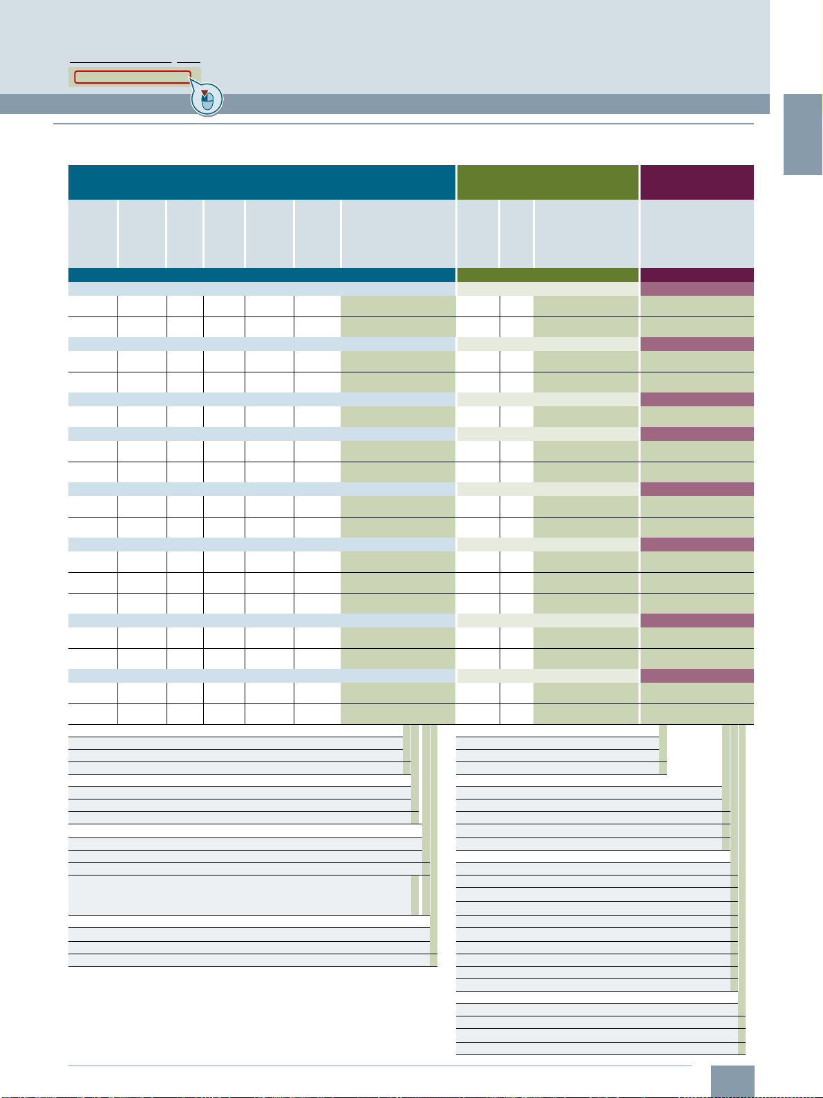
■
Order overview
SINAMICS S210 drive system for line connection 200 ... 240 V 3 AC
SIMOTICS S-1FK2 servomotor SINAMICS S210 servo converter
Static
torque
M
0
Nm
(lb
High Dynamic for highly dynamic applications SINAMICS S210 servo converter One Cable Connection
Shaft height 20 – rated speed n
0.16
(0.12)
0.32
(0.24)
Shaft height 30 – rated speed n
0.64
(0.47)
1.27
(0.94)
Shaft height 40 – rated speed n
1.27
(0.94)
2.4
(1.77)
3.2
(2.36)
Shaft height 40 – rated speed n
1.27
(0.94)
2.4
(1.77)
Shaft height 52 – rated speed n
5
(3.69)
8
(5.90)
Shaft height 63 – rated speed n
9
(6.64)
12
(8.85)
16
(11.80)
Article No. supplements
Holding brake Pre-assembled MOTION-CONNECT cable
Without brake 0 MOTION-CONNECT 500 5
With brake 1 MOTION-CONNECT 800PLUS 8
Maximum
torque
M
Nm
-ft)
(lb
f
0.56
(0.41)
1.11
(0.82)
1.95
(1.44)
4.05
(2.99)
3.75
(2.77)
7.5
(5.53)
10
(7.38)
3.85
(2.84)
7.6
(5.61)
15
(11.06)
24
(17.70)
24.5
(18.07)
32.5
(23.97)
42
(30.98)
max
-ft) rpm
f
Maxi-
Rated
mum
speed
n
maxPratedMrated
8000 0.05
8000 0.1
8000 0.2
8000 0.4
7200 0.2
6700 0.38
7200 0.5
8000 0.4
8000 0.75
6000 0.79
6000 1.26
6000 1.3
6000 1.64
6000 2.15
Rated
power
torque
240 V
kW
Nm
(hp)
(lb
3000 rpm
rated
0.16
(0.07)
(0.12)
0.32
(0.13)
(0.24)
3000 rpm
rated
0.64
(0.27)
(0.47)
1.27
(0.54)
(0.94)
1500 rpm
rated
1.27
(0.27)
(0.94)
2.4
(0.51)
(1.77)
3.2
(0.67)
(2.36)
3000 rpm
rated
1.27
(0.54)
(0.94)
2.4
(1.01)
(1.77)
1500 rpm
rated
(1.06)5 (3.69)
(1.69)8 (5.90)
1500 rpm
rated
8.3
(1.74)
(6.12)
10.5
(2.20)
(7.74)
13.8
(2.88)
(10.18)
Rotor
moment
of inertia
J
Mot
kg cm
-ft)
(lbf-in2) Article No.
f
0.025
(0.009)
0.036
(0.012)
0.093
(0.032)
0.14
(0.048)
0.35
(0.120)
0.56
(0.191)
0.76
(0.260)
0.35
(0.120)
0.56
(0.191)
1.7
(0.581)
2.7
(0.923)
4.6
(1.572)
6.0
(2.050)
8.7
(2.973)
2
1FK2102-0AG■■-■■A0 0.24 FSA 6SL3210-5HE10-4UF0 6FX■002-8QN04-1■■■
1FK2102-1AG■■-■■A0 0.24 FSA 6SL3210-5HE10-4UF0 6FX■002-8QN04-1■■■
1FK2103-2AG■■-■■A0 0.45 FSA 6SL3210-5HE10-8UF0 6FX■002-8QN04-1■■■
1FK2103-4AG■■-■■A0 0.6 FSA 6SL3210-5HE11-0UF0 6FX■002-8QN04-1■■■
1FK2104-4AF■■-■■A0 0.24 FSA 6SL3210-5HE10-4UF0 6FX■002-8QN08-1■■■
1FK2104-5AF■■-■■A0 0.45 FSA 6SL3210-5HE10-8UF0 6FX■002-8QN08-1■■■
1FK2104-6AF■■-■■A0 0.6 FSA 6SL3210-5HE11-0UF0 6FX■002-8QN08-1■■■
1FK2104-4AK■■-■■A0 0.6 FSA 6SL3210-5HE11-0UF0 6FX■002-8QN08-1■■■
1FK2104-5AK■■-■■A0 0.9 FSB 6SL3210-5HE11-5UF0 6FX■002-8QN08-1■■■
1FK2105-4AF■■-■■A0 0.9 FSB 6SL3210-5HE11-5UF0 6FX■002-8QN08-1■■■
1FK2105-6AF■■-■■A0 1.2 FSB 6SL3210-5HE12-0UF0 6FX■002-8QN08-1■■■
1FK2106-3AF■■-■■A0 3FSC6SL3210-5HE15-0UF0 6FX■002-8QN11-1■■■
1FK2106-4AF■■-■■A0 3FSC6SL3210-5HE15-0UF0 6FX■002-8QN11-1■■■
1FK2106-6AF■■-■■A0 4.2 FSC 6SL3210-5HE17-0UF0 6FX■002-8QN11-1■■■
(3 AC series)
Supply voltage 200 ... 240 V 3 AC
Rated
power
240 V
P
kW
rated
Frame
size
Article No. Article No.
MOTION-CONNECT
motor connection cable
Degree of protection Length code (max. 50 m (164 ft))
IP64 (without shaft sealing ring) 0 0 m (0 ft) A
IP65 (with shaft sealing ring) 1 10 m (32.8 ft) B
Shaft extension / feather key 50 m (164 ft) F
Plain shaft 0
Shaft with feather key 1 0 m (0 ft) A
Plain shaft, reduced shaft diameter 0 2 1 m (3.28 ft) B
• ∅11 × 23 mm (0.43 × 0.91 in) (only for 1FK2.03 and IP64)
• ∅14 × 30 mm (0.55 × 1.18 in) (only for 1FK2.04 and IP64)
Encoder 5 m (16.4 ft) F
AS22DQC (absolute encoder 22-bit singleturn) S 6 m (19.7 ft) G
AM22DQC (absolute encoder 22-bit + 12-bit multiturn) M 7 m (23.0 ft) H
When operating a SINAMICS S210 servo converter with a supply
voltage of 200 V to 240 V 3 AC, an external, intrinsically safe
braking resistor is always required.
1/14
Siemens D 32 · January 2020
...
2 m (6.56 ft) C
3 m (9.84 ft) D
4 m (13.1 ft) E
8 m (26.2 ft) J
9 m (29.5 ft) K
0 m (0 ft) 0
0.1 m (0.33 ft) 1
...
0.8 m (2.62 ft) 8
...
...
Page 23
1
Clicking to the Industry Mall
6SL3255-0AA00-5AA0
© Siemens 2020
System overview
SINAMICS S210 servo drive system
■
Order overview
SINAMICS S210 drive system for line connection 200 ... 240 V 3 AC (continued)
SIMOTICS S-1FK2 servomotor SINAMICS S210 servo converter
Static
torque
M
0
Nm
(lb
Compact for high precision applications SINAMICS S210 servo converter One Cable Connection
Shaft height 30 – rated speed n
0.64
(0.47)
1.27
(0.94)
Shaft height 40 – rated speed n
2.4
(1.77)
3.2
(2.36)
Shaft height 40 – rated speed n
2.4
(1.77)
Shaft height 48 – rated speed n
3.6
(2.66)
6
(4.43)
Shaft height 63 – rated speed n
6.5
(4.79)
12
(8.85)
Shaft height 80 – rated speed n
18
(13.28)
22
(16.23)
27
(19.92)
Shaft height 100 – rated speed n
30
(22.13)
40
(29.50)
Shaft height 100 – rated speed n
30
(22.13)
40
(29.50)
Article No. supplements
Holding brake Pre-assembled MOTION-CONNECT cable
Without brake 0 MOTION-CONNECT 500 5
With brake 1 MOTION-CONNECT 800PLUS 8
Maximum
torque
M
Nm
-ft)
(lb
f
1.85
(1.36)
3.75
(2.77)
7.1
(5.24)
9.5
(7.01)
7.1
(5.24)
10.8
(7.97)
18
(13.28)
18
(13.28)
36
(26.55)
51
(37.62)
66
(48.68)
80
(59.01)
90
(66.38)
120
(88.51)
90
(66.38)
120
(88.51)
max
-ft) rpm
f
Maxi-
Rated
power
240 V
kW
(hp)
rated
(0.27)
(0.54)
rated
(0.51)
(0.67)
rated
(1.01)
rated
(0.71)
(1.15)
rated
(1.30)
(2.31)
rated
(2.33)
(2.88)
(3.35)
rated
(3.35)
(4.09)
rated
(4.29)
(5.23)
Rated
torque
Nm
(lb
3000 rpm
0.64
(0.47)
1.27
(0.94)
1500 rpm
2.4
(1.77)
3.2
(2.36)
3000 rpm
2.4
(1.77)
1500 rpm
3.4
(2.51)
5.5
(4.06)
1500 rpm
6.1
(4.50)
10.9
(8.04)
1000 rpm
16.6
(12.24)
20
(14.75)
23.5
(17.33)
750 rpm
30
(22.13)
39
(28.77)
1000 rpm
30
(22.13)
37
(27.29)
mum
speed
n
maxPratedMrated
8000 0.2
8000 0.4
7500 0.38
7600 0.5
8000 0.75
6000 0.53
6000 0.86
6000 0.97
5800 1.72
4100 1.74
4600 2.15
4700 2.5
2500 2.5
2500 3.05
4400 3.2
3300 3.9
Rotor
moment
of inertia
J
Mot
kg cm
-ft)
(lbf-in2) Article No.
f
0.20
(0.068)
0.35
(0.120)
1.2
(0.410)
1.6
(0.547)
1.2
(0.410)
3.2
(1.093)
5.1
(1.743)
7.8
(2.665)
15
(5.126)
30
(10.251)
39
(13.326)
48
(16.402)
89
(30.411)
120
(41.004)
89
(30.411)
120
(41.004)
2
1FK2203-2AG■■-■■A0 0.45 FSA 6SL3210-5HE10-8UF0 6FX■002-8QN04-1■■■
1FK2203-4AG■■-■■A0 0.6 FSA 6SL3210-5HE11-0UF0 6FX■002-8QN04-1■■■
1FK2204-5AF■■-■■A0 0.45 FSA 6SL3210-5HE10-8UF0 6FX■002-8QN08-1■■■
1FK2204-6AF■■-■■A0 0.6 FSA 6SL3210-5HE11-0UF0 6FX■002-8QN08-1■■■
1FK2204-5AK■■-■■A0 0.9 FSB 6SL3210-5HE11-5UF0 6FX■002-8QN08-1■■■
1FK2205-2AF■■-■■A0 0.6 FSA 6SL3210-5HE11-0UF0 6FX■002-8QN08-1■■■
1FK2205-4AF■■-■■A0 0.9 FSB 6SL3210-5HE11-5UF0 6FX■002-8QN08-1■■■
1FK2206-2AF■■-■■A0 0.9 FSB 6SL3210-5HE11-5UF0 6FX■002-8QN11-1■■■
1FK2206-4AF■■-■■A0 2.1 FSC 6SL3210-5HE13-5UF0 6FX■002-8QN11-1■■■
1FK2208-3AC■■-■■A0 2.1 FSC 6SL3210-5HE13-5UF0 6FX■002-8QN11-1■■■
1FK2208-4AC■■-■■A0 3FSC6SL3210-5HE15-0UF0 6FX■002-8QN11-1■■■
1FK2208-5AC■■-■■A0 4.2 FSC 6SL3210-5HE17-0UF0 6FX■002-8QN11-1■■■
1FK2210-3AB■■-■■A0 2.1 FSC 6SL3210-5HE13-5UF0 6FX■002-8QN11-1■■■
1FK2210-4AB■■-■■A0 3FSC6SL3210-5HE15-0UF0 6FX■002-8QN11-1■■■
1FK2210-3AC■■-■■A0 4.2 FSC 6SL3210-5HE17-0UF0 6FX■002-8QN11-1■■■
1FK2210-4AC■■-■■A0 4.2 FSC 6SL3210-5HE17-0UF0 6FX■002-8QN11-1■■■
(3 AC series)
Supply voltage 200 ... 240 V 3 AC
Rated
power
240 V
P
kW
rated
Frame
size
Article No. Article No.
MOTION-CONNECT
motor connection cable
Degree of protection Length code (max. 50 m (164 ft))
IP64 (without shaft sealing ring) 0 0 m (0 ft) A
IP65 (with shaft sealing ring) 1 10 m (32.8 ft) B
Shaft extension / feather key 50 m (164 ft) F
Plain shaft 0
Shaft with feather key 1 0 m (0 ft) A
Plain shaft, reduced shaft diameter 0 2 1 m (3.28 ft) B
• ∅11 × 23 mm (0.43 × 0.91 in) (only for 1FK2.03 and IP64)
• ∅14 × 30 mm (0.55 × 1.18 in) (only for 1FK2.04 and IP64)
Encoder 5 m (16.4 ft) F
AS22DQC (absolute encoder 22-bit singleturn) S 6 m (19.7 ft) G
AM22DQC (absolute encoder 22-bit + 12-bit multiturn) M 7 m (23.0 ft) H
When operating a SINAMICS S210 servo converter with a supply
voltage of 200 V to 240 V 3 AC, an external, intrinsically safe
braking resistor is always required.
...
2 m (6.56 ft) C
3 m (9.84 ft) D
4 m (13.1 ft) E
8 m (26.2 ft) J
9 m (29.5 ft) K
0 m (0 ft) 0
0.1 m (0.33 ft) 1
...
0.8 m (2.62 ft) 8
Siemens D 32 · January 2020
...
1/15
...
Page 24
1
© Siemens 2020
System overview
Clicking to the Industry Mall
6SL3255-0AA00-5AA0
SINAMICS S210 servo drive system
■
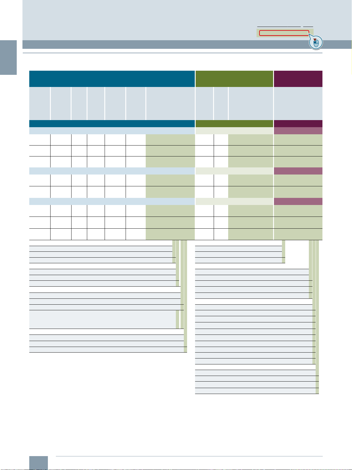
Order overview
SINAMICS S210 drive system for line connection 380 ... 480 V 3 AC
SIMOTICS S-1FK2 servomotor SINAMICS S210 servo converter
Static
torque
M
0
Nm
(lb
High Dynamic for highly dynamic applications SINAMICS S210 servo converter One Cable Connection
Shaft height 40 – rated speed n
1.27
(0.94)
2.4
(1.77)
3.2
(2.36)
Shaft height 52 – rated speed n
5
(3.69)
8
(5.90)
Shaft height 63 – rated speed n
9
(6.64)
12
(8.85)
16
(11.80)
Article No. supplements
Holding brake Pre-assembled MOTION-CONNECT cable
Without brake 0 MOTION-CONNECT 500 5
With brake 1 MOTION-CONNECT 800PLUS 8
Maximum
torque
M
Nm
-ft)
(lb
f
3.75
(2.77)
7.5
(5.53)
10
(7.38)
15
(11.06)
24
(17.70)
24.5
(18.07)
32.5
(23.97)
42
(30.98)
max
-ft) rpm
f
Maxi-
Rated
power
400 V
kW
(hp)
rated
(0.54)
(1.01)
(1.34)
rated
(1.94)
(2.82)
rated
(3.08)
(3.62)
(4.43)
Rated
torque
Nm
(lb
3000 rpm
1.27
(0.94)
2.4
(1.77)
3.2
(2.36)
3000 rpm
4.6
(3.39)
6.6
(4.87)
3000 rpm
7.3
(5.38)
8.6
(6.34)
10.6
(7.82)
mum
speed
n
maxPratedMrated
7200 0.4
6700 0.75
7200 1
6000 1.45
6000 2.1
6000 2.3
6000 2.7
6000 3.3
Rotor
moment
of inertia
J
Mot
kg cm
-ft)
(lbf-in2) Article No.
f
0.35
(0.120)
0.56
(0.191)
0.76
(0.260)
1.7
(0.581)
2.7
(0.923)
4.6
(1.572)
6.0
(2.050)
8.7
(2.973)
2
1FK2104-4AF■■-■■A0 0.4 FSA 6SL3210-5HE10-4UF0 6FX■002-8QN08-1■■■
1FK2104-5AF■■-■■A0 0.75 FSA 6SL3210-5HE10-8UF0 6FX■002-8QN08-1■■■
1FK2104-6AF■■-■■A0 1FSA6SL3210-5HE11-0UF0 6FX■002-8QN08-1■■■
1FK2105-4AF■■-■■A0 1.5 FSB 6SL3210-5HE11-5UF0 6FX■002-8QN08-1■■■
1FK2105-6AF■■-■■A0 2FSB6SL3210-5HE12-0UF0 6FX■002-8QN08-1■■■
1FK2106-3AF■■-■■A0 5FSC6SL3210-5HE15-0UF0 6FX■002-8QN11-1■■■
1FK2106-4AF■■-■■A0 5FSC6SL3210-5HE15-0UF0 6FX■002-8QN11-1■■■
1FK2106-6AF■■-■■A0 7FSC6SL3210-5HE17-0UF0 6FX■002-8QN11-1■■■
(3 AC series)
Supply voltage 380 ... 480 V 3 AC
Rated
power
400 V
P
kW
rated
Frame
size
Article No. Article No.
MOTION-CONNECT
motor connection cable
Degree of protection Length code (max. 50 m (164 ft))
IP64 (without shaft sealing ring) 0 0 m (0 ft) A
IP65 (with shaft sealing ring) 1 10 m (32.8 ft) B
Shaft extension / feather key 50 m (164 ft) F
Plain shaft 0
Shaft with feather key 1 0 m (0 ft) A
Plain shaft, reduced shaft diameter 0 2 1 m (3.28 ft) B
• ∅11 × 23 mm (0.43 × 0.91 in) (only for 1FK2.03 and IP64)
• ∅14 × 30 mm (0.55 × 1.18 in) (only for 1FK2.04 and IP64)
Encoder 5 m (16.4 ft) F
AS22DQC (absolute encoder 22-bit singleturn) S 6 m (19.7 ft) G
AM22DQC (absolute encoder 22-bit + 12-bit multiturn) M 7 m (23.0 ft) H
...
2 m (6.56 ft) C
3 m (9.84 ft) D
4 m (13.1 ft) E
8 m (26.2 ft) J
9 m (29.5 ft) K
0 m (0 ft) 0
0.1 m (0.33 ft) 1
...
0.8 m (2.62 ft) 8
...
...
1/16
Siemens D 32 · January 2020
Page 25
1
Clicking to the Industry Mall
6SL3255-0AA00-5AA0
© Siemens 2020
System overview
SINAMICS S210 servo drive system
■
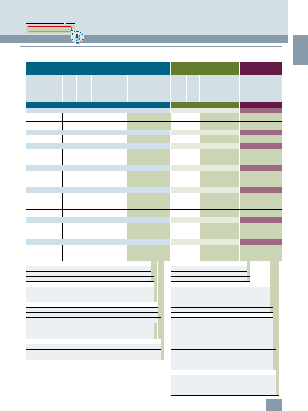
Order overview
SINAMICS S210 drive system for line connection 380 ... 480 V 3 AC (continued)
SIMOTICS S-1FK2 servomotor SINAMICS S210 servo converter
Static
torque
M
0
Nm
(lb
Compact for high precision applications SINAMICS S210 servo converter One Cable Connection
Shaft height 40 – rated speed n
2.4
(1.77)
3.2
(2.36)
Shaft height 40 – rated speed n
2.4
(1.77)
Shaft height 48 – rated speed n
3.6
(2.66)
6
(4.43)
Shaft height 63 – rated speed n
6.5
(4.79)
12
(8.85)
Shaft height 80 – rated speed n
18
(13.28)
22
(16.23)
27
(19.92)
Shaft height 100 – rated speed n
30
(22.13)
40
(29.50)
Shaft height 100 – rated speed n
30
(22.13)
40
(29.50)
Article No. supplements
Holding brake Pre-assembled MOTION-CONNECT cable
Without brake 0 MOTION-CONNECT 500 5
With brake 1 MOTION-CONNECT 800PLUS 8
Maximum
torque
M
Nm
-ft)
(lb
f
7.1
(5.24)
9.5
(7.01)
7.1
(5.24)
10.8
(7.97)
18
(13.28)
18
(13.28)
36
(26.55)
51
(37.62)
66
(48.68)
80
(59.01)
90
(66.38)
120
(88.51)
90
(66.38)
120
(88.51)
max
-ft) rpm
f
Maxi-
Rated
mum
speed
n
maxPratedMrated
7500 0.75
7600 1
8000 0.57
6000 0.94
6000 1.45
6000 1.71
5800 2.85
4100 3.05
4600 3.55
4700 4
2500 4.5
2500 5.4
4400 5.5
3300 6.4
Rated
power
torque
400 V
kW
Nm
(hp)
(lb
3000 rpm
rated
2.4
(1.01)
(1.77)
3.2
(1.34)
(2.36)
6000 rpm
rated
0.9
(0.76)
(0.66)
3000 rpm
rated
(1.26)3 (2.21)
4.6
(1.94)
(3.39)
3000 rpm
rated
5.4
(2.29)
(3.98)
9.1
(3.82)
(6.71)
2000 rpm
rated
14.5
(4.09)
(10.70)
17
(4.76)
(12.54)
19.1
(5.36)
(14.09)
1500 rpm
rated
28.5
(6.03)
(21.02)
34.5
(7.24)
(25.45)
2000 rpm
rated
26
(7.38)
(19.18)
30.5
(8.58)
(22.50)
Rotor
moment
of inertia
J
Mot
kg cm
-ft)
(lbf-in2) Article No.
f
1.2
(0.410)
1.6
(0.547)
1.2
(0.410)
3.2
(1.093)
5.1
(1.743)
7.8
(2.665)
15
(5.126)
30
(10.251)
39
(13.326)
48
(16.402)
89
(30.411)
120
(41.004)
89
(30.411)
120
(41.004)
2
1FK2204-5AF■■-■■A0 0.75 FSA 6SL3210-5HE10-8UF0 6FX■002-8QN08-1■■■
1FK2204-6AF■■-■■A0 1FSA6SL3210-5HE11-0UF0 6FX■002-8QN08-1■■■
1FK2204-5AK■■-■■A0 1.5 FSB 6SL3210-5HE11-5UF0 6FX■002-8QN08-1■■■
1FK2205-2AF■■-■■A0 1FSA6SL3210-5HE11-0UF0 6FX■002-8QN08-1■■■
1FK2205-4AF■■-■■A0 1.5 FSB 6SL3210-5HE11-5UF0 6FX■002-8QN08-1■■■
1FK2206-2AF■■-■■A0 1.5 FSB 6SL3210-5HE11-5UF0 6FX■002-8QN11-1■■■
1FK2206-4AF■■-■■A0 3.5 FSC 6SL3210-5HE13-5UF0 6FX■002-8QN11-1■■■
1FK2208-3AC■■-■■A0 3.5 FSC 6SL3210-5HE13-5UF0 6FX■002-8QN11-1■■■
1FK2208-4AC■■-■■A0 5FSC6SL3210-5HE15-0UF0 6FX■002-8QN11-1■■■
1FK2208-5AC■■-■■A0 7FSC6SL3210-5HE17-0UF0 6FX■002-8QN11-1■■■
1FK2210-3AB■■-■■A0 3.5 FSC 6SL3210-5HE13-5UF0 6FX■002-8QN11-1■■■
1FK2210-4AB■■-■■A0 5FSC6SL3210-5HE15-0UF0 6FX■002-8QN11-1■■■
1FK2210-3AC■■-■■A0 7FSC6SL3210-5HE17-0UF0 6FX■002-8QN11-1■■■
1FK2210-4AC■■-■■A0 7FSC6SL3210-5HE17-0UF0 6FX■002-8QN11-1■■■
(3 AC series)
Supply voltage 380 ... 480 V 3 AC
Rated
power
400 V
P
kW
rated
Frame
size
Article No. Article No.
MOTION-CONNECT
motor connection cable
Degree of protection Length code (max. 50 m (164 ft))
IP64 (without shaft sealing ring) 0 0 m (0 ft) A
IP65 (with shaft sealing ring) 1 10 m (32.8 ft) B
Shaft extension / feather key 50 m (164 ft) F
Plain shaft 0
Shaft with feather key 1 0 m (0 ft) A
Plain shaft, reduced shaft diameter 0 2 1 m (3.28 ft) B
• ∅11 × 23 mm (0.43 × 0.91 in) (only for 1FK2.03 and IP64)
• ∅14 × 30 mm (0.55 × 1.18 in) (only for 1FK2.04 and IP64)
Encoder 5 m (16.4 ft) F
AS22DQC (absolute encoder 22-bit singleturn) S 6 m (19.7 ft) G
AM22DQC (absolute encoder 22-bit + 12-bit multiturn) M 7 m (23.0 ft) H
...
2 m (6.56 ft) C
3 m (9.84 ft) D
4 m (13.1 ft) E
8 m (26.2 ft) J
9 m (29.5 ft) K
0 m (0 ft) 0
0.1 m (0.33 ft) 1
...
0.8 m (2.62 ft) 8
Siemens D 32 · January 2020
...
1/17
...
Page 26
1
1)
Extended function for an existing memory card (firmware V5.1 SP1 or
higher). The memory card is not included in the scope of delivery.
The Safety license can also be ordered together with a memory card
(see above). With a CoL in electronic form, the license is supplied as a
PDF file. Notification of this with a download link is received by email.
For further information, see section Supplementary system components >
Memory cards.
2)
The data is applicable for the complete cable length of the motors, whose
associated converters are coupled with one another via an AC coupling or
through the DC link.
The maximum cable length per motor is 25 m using the internal filters or an
external filter to achieve EMC category C2. If an external filter is used to
achieve EMC category C3, the maximum cable length per motor is 50 m.
3)
Permissible cables:
-16mm
2
, Class 5 (finely stranded, PVC-insulated) H07V-K + H07V2-K
according to EN 50525-2-31
- HELUTHERM 145: 16 mm
2
, Class 5 (finely stranded, crosslinked
polyolefin-copolymer, halogen-free)
www.helukabel.com
- External diameter 6.7 mm to 8.1 mm
Permissible cables (UL approval):
- AWG 6, copper cable with PVC insulation, with or without nylon jacket,
19 strands
- Types: MTW, THHW, THW, THW-2, THHN, THWN-2, TW, TWN
- CSA types: TW, TWU, TWN75, TW75, TWU75, T90, no compressed
conductors
© Siemens 2020
System overview
SINAMICS S210 servo drive system
■
Order overview
Accessories for SINAMICS S210 servo converters Accessories for SIMOTICS S-1FK2 servomotors
Description Article No.
SINAMICS SD card (optional)
512 MB
The parameter assignment, firmware and
licenses for a converter can be stored on
this memory card.
Firmware V5.2 or higher is required for the
3 AC series.
•Empty 6SL3054-4AG00-2AA0
• With firmware V5.1
• With firmware V5.1 SP1
• With firmware V5.1 SP1 and
Safety license (Extended Functions)
• With firmware V5.2
• With firmware V5.2 and
Safety license (Extended Functions)
• With firmware V5.2 SP3
• With firmware V5.2 SP3 and
Safety license (Extended Functions)
Safety license
(Extended Functions)
• CoL in paper form 6SL3074-0AA10-0AA0
• CoL in electronic form
PROFINET patch cable
For the networking of concatenated
converters
•0.3m 6XV1870-3QE30
•0.5m
Only for the 1 AC series
Line filter
With this line filter, Category C2 for cable
lengths up to 25 m (82 ft), Category C3 for
cable lengths up to 50 m (164 ft) acc. to
IEC 61800-3 can be achieved.
Only for the 3 AC series
Line filter
With these line filters, Category C2 for cable lengths
up to 25 m (82 ft), Category C3 for cable lengths
up to 50 m (164 ft) acc. to IEC 61800-3 can be
achieved.
When connected via a DC link, a total cable
length of up to 100 m (328 ft) with Category C2
and up to 250 m (820 ft) with Category C3 is
2)
possible
• ≤ 35 A 6SL3203-0BE23-5HA0
• ≤ 65 A
Connector set AC bus and DC link
For coupling the DC link and the line infeed
Scope of delivery: 1 AC bus connector,
1 DC link connector, 2 cover caps
The AC bus connector replaces the push-
in connector included in the scope of delivery of the converter. Wiring is performed
with conventional 16 mm
included in scope of delivery)
Connector set AC bus individual
For coupling the line infeed
Scope of delivery: 1 AC bus connector,
1 cover cap
This connector replaces the push-in
connector included in the scope of delivery
of the converter. Wiring is performed with
conventional 16 mm
in scope of delivery)
External braking resistors
for 200 … 240 V 3 AC
For a supply voltage of 200 V to 240 V 3 AC,
an external, intrinsically safe braking resistor
is always required for each converter
• 100 W, 47 Ω for FSA and FSB GXK:BWG250047TS-190
• 240 W, 14 Ω for FSC
1/18
1)
2
cable (not
3)
2
cable (not included
3)
Siemens D 32 · January 2020
6SL3054-4FB00-2BA0
6SL3054-4FB10-2BA0
6SL3054-4FB10-2BA0-Z
F01
6SL3054-4FC00-2BA0
6SL3054-4FC00-2BA0-Z
F01
6SL3054-4FC30-2BA0
6SL3054-4FC30-2BA0-Z
F01
6SL3074-0AA10-0AH0
6XV1870-3QE50
6SL3203-0BB21-8VA1
6SL3203-0BE26-5HA0
6SL3260-2DC00-0AA0
6SL3260-2DC10-0AA0
GXK:BWG600014TS-190
Description For motor Article No.
Shaft sealing ring (optional)
To achieve degree of protection
IP65 for retrofitting or as spare
part
Starter kit
Description Article No.
SINAMICS S210 starter kit
with Extended Safety
Scope of delivery:
• SINAMICS S210 servo converter,
230V1AC, 400W
• SIMOTICS S-1FK2 servomotor,
High Dynamic, shaft height 30, 400 W,
without brake, shaft with feather key,
with absolute encoder multiturn
• One Cable Connection (OCC) motor
connection cables, 3 m (9.84 ft)
• Memory card with firmware V5.2 and
Safety license (Extended Functions)
The delivery quantity is limited to three units
per customer
Training case
Description Article No.
SINAMICS S210 training case 6AG1067-1AA33-0AA0
Scope of delivery:
• 2 × SINAMICS S210 servo converters,
0.1kW, 230V1AC
• 2 × SIMOTICS S-1FK2 servomotors,
High Dynamic
• 2 × One Cable Connection (OCC) motor
connection cables
• Rail, prepared for installation of a
controller, e.g. SIMATIC S7-1500
(controller not included in scope of
delivery)
The SINAMICS S210 training case is
supplied as a trolley with a hood.
Change 07/2020
Clicking to the Industry Mall
6SL3255-0AA00-5AA0
1FK2.02
1FK2.03
1FK2.04
1FK2902-0GC00
1FK2903-0GC00
1FK2904-0GC00
6SL3200-0AE61-0AA0
Page 27
1
■
1)
Available soon.
2)
For increased requirement regarding routing type and ambient temperature.
See tables in the section MOTION-CONNECT connection systems >
More information > Current carrying capacity and derating factors.
Recommended SIMATIC S7 controller
Further information about SIMATIC S7-1500 and
SIMATIC S7-1500 T-CPU controllers is available in
Catalog ST 70 and on the Internet at
www.siemens.com/simatic-s7-1500
Clicking to the Industry Mall
6SL3255-0AA00-5AA0
Order overview
Accessories for MOTION-CONNECT connection systems
OCC extension cables
Description Cross-
Pre-assembled
OCC extension cable
MOTION-CONNECT 500
Pre-assembled
OCC extension cable
MOTION-CONNECT
800PLUS
Pre-assembled
OCC extension cable
MOTION-CONNECT 500
(male contacts fixed at the
converter end, insulators and
connector housing supplied
with cable)
Pre-assembled
OCC extension cable
MOTION-CONNECT
800PLUS
(male contacts fixed at the
converter end, insulators and
connector housing supplied
with cable)
1)
1)
For motor OCC extension cable
section
2
mm
0.38 1FK2102,
1FK2.03
0.75 1FK2.04,
1FK2.05
1.5 1FK2.06,
1FK2.08,
1FK2.10
2.5 2)1FK2.06,
1FK2.08,
1FK2.10
0.38 1FK2102,
1FK2.03
0.75 1FK2.04,
1FK2.05
1.5 1FK2.06,
1FK2.08,
1FK2.10
2.5 2)1FK2.06,
1FK2.08,
1FK2.10
0.38 1FK2102,
1FK2.03
0.75 1FK2.04,
1FK2.05
1.5 1FK2.06,
1FK2.08,
1FK2.10
2.5 2)1FK2.06,
1FK2.08,
1FK2.10
0.38 1FK2102,
1FK2.03
0.75 1FK2.04,
1FK2.05
1.5 1FK2.06,
1FK2.08,
1FK2.10
2.5 2)1FK2.06,
1FK2.08,
1FK2.10
(for length code, see
SINAMICS S210 drive
system table)
Article No.
6FX5002-8QE04-1■■■
6FX5002-8QE08-1■■■
6FX5002-8QE11-1■■■
6FX5002-8QE21-1■■■
6FX8002-8QE04-1■■■
6FX8002-8QE08-1■■■
6FX8002-8QE11-1■■■
6FX8002-8QE21-1■■■
6FX5012-8QE04-1■■■
6FX5012-8QE08-1■■■
6FX5012-8QE11-1■■■
6FX5012-8QE21-1■■■
6FX8012-8QE04-1■■■
6FX8012-8QE08-1■■■
6FX8012-8QE11-1■■■
6FX8012-8QE21-1■■■
OCC components for self assembly
Description Cross-
Sold by the meter OCC line
MOTION-CONNECT 500
1)
For motor OCC component
section
2
mm
0.38 1FK2102,
1FK2.03
0.75 1FK2.04,
1FK2.05
1.5 1FK2.06,
1FK2.08,
1FK2.10
2.5 2)1FK2.06,
1FK2.08,
1FK2.10
(for length code, see
SINAMICS S210 drive
system table)
Article No.
6FX5008-1BE04-1■■■
6FX5008-1BE08-1■■■
6FX5008-1BE11-1■■■
6FX5008-1BE21-1■■■
© Siemens 2020
OCC components for self assembly (continued)
Description Cross-
Sold by the meter OCC line
MOTION-CONNECT
800PLUS
Motor-side
SPEED-CONNECT
connector
• M12 0.38 1FK2102,
• M17 0.75 1FK2.04,
• M23 1.5
SPEED-CONNECT
connector with
external thread for
extension cable
• M12 0.38 1FK2102,
• M17 0.75 1FK2.04,
• M23 1.5
Converter-side Siemens IX
signal connector
Shield clamp
(Packing unit: 10 items)
• For pre-assembled cables
with M12 and M17
connectors
• For pre-assembled cables
with M23 connectors
Control cabinet bushings
Description For motor Article No.
Mounting flange 1FK2102,
System overview
SINAMICS S210 servo drive system
For motor OCC component
section
2
mm
0.38 1FK2102,
1)
1)
1)
1)
1FK2.03
0.75 1FK2.04,
1FK2.05
1.5 1FK2.06,
1FK2.08,
1FK2.10
2.5 2)1FK2.06,
1FK2.08,
1FK2.10
1FK2.03
1FK2.05
1FK2.06,
and
1FK2.08,
2.5
1FK2.10
1FK2.03
1FK2.05
1FK2.06,
and
1FK2.08,
2.5
1FK2.10
–– 6FX2003-0DE01
0.38
– 6FX2003-7EX10
and
0.75
1.5
–
and
2.5
1FK2.03
1FK2.04,
1FK2.05
1FK2.06,
1FK2.08,
1FK2.10
(for length code, see
SINAMICS S210 drive
system table)
Article No.
6FX8008-1BE04-1■■■
6FX8008-1BE08-1■■■
6FX8008-1BE11-1■■■
6FX8008-1BE21-1■■■
6FX2003-0LU64
6FX2003-0LU54
6FX2003-0LU34
6FX2003-0LA64
6FX2003-0LA54
6FX2003-0LA34
6FX2003-7EX11
6FX2003-7JX00
6FX2003-7HX00
6FX2003-7BX00
Siemens D 32 · January 2020
1/19
Page 28
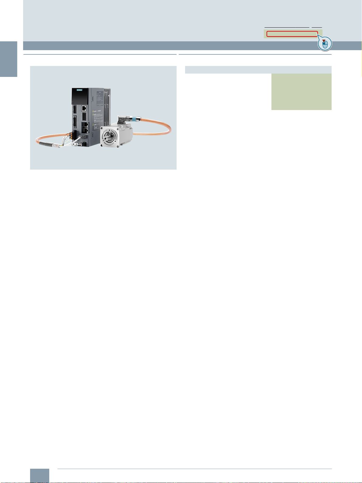
1
© Siemens 2020
System overview
SINAMICS S210 starter kit
■
Overview
The SINAMICS S210 starter kit with Extended Safety with
Article No. 6SL3200-0AE61-0AA0 comprises
• a SINAMICS S210 servo converter, 230 V 1 AC, 400 W
(Article No. 6SL3210-5HB10-4UF0)
• a SIMOTICS S-1FK2 servomotor, High Dynamic, shaft height 30,
400 W, without brake, shaft with feather key, with absolute
encoder multiturn (Article No. 1FK2103-4AG00-1MA0)
• a corresponding One Cable Connection cable (OCC),
3m (9.84ft)
• a memory card with firmware V5.2 and
Safety license (Extended Functions)
(Article No. 6SL3054-4FC00-2BA0-Z F01)
The delivery quantity is limited to three per customer.
The SINAMICS S210 starter kit can be perfectly combined with
the SIMATIC S7-1500 starter kit. In this way, Motion Control
applications can be quickly and easily implemented.
For more information on SIMATIC S7-1500 starter kits, see:
www.siemens.com/s7-1500-starterkits
(Article No. 6FX5002-8QN04-1AD0)
Clicking to the Industry Mall
6SL3255-0AA00-5AA0
■
Selection and ordering data
Description Article No.
SINAMICS S210 starter kit
with Extended Safety
With SINAMICS S210 servo converter,
SIMOTICS S-1FK2 servomotor
(power rating 400 W), OCC cable
(3 m (9.84 ft)) and memory card with
Safety license (Extended Functions)
6SL3200-0AE61-0AA0
1/20
Siemens D 32 · January 2020
Change 07/2020
Page 29
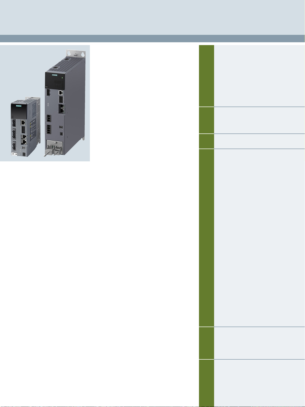
SINAMICS S210 servo drive
© Siemens 2020
2
2/2 SINAMICS S210 servo drive
2/2 Overview
2/4 Design
2/5 Function
2/5 Configuration
2/6 Integration
2/8 Selection and ordering data
2/10 Technical specifications
2/13 Dimensional drawings
2/14 Accessories
2/15 Line-side components
2/15 Line filters
2/16 Recommended line-side overcurrent
protection devices
2/17 DC link components
2/17 External braking resistors
2/18 Supplementary system components
2/18 Memory cards
Detailed technical information on the
SINAMICS S210 servo drive system is
available on the Internet at
www.siemens.com/sinamics-s210/
documentation
In addition, the Drive Technology
Configurator (DT Configurator) can be
used on the Internet at the following
address:
www.siemens.com/dt-configurator
Siemens D 32 · January 2020
Page 30
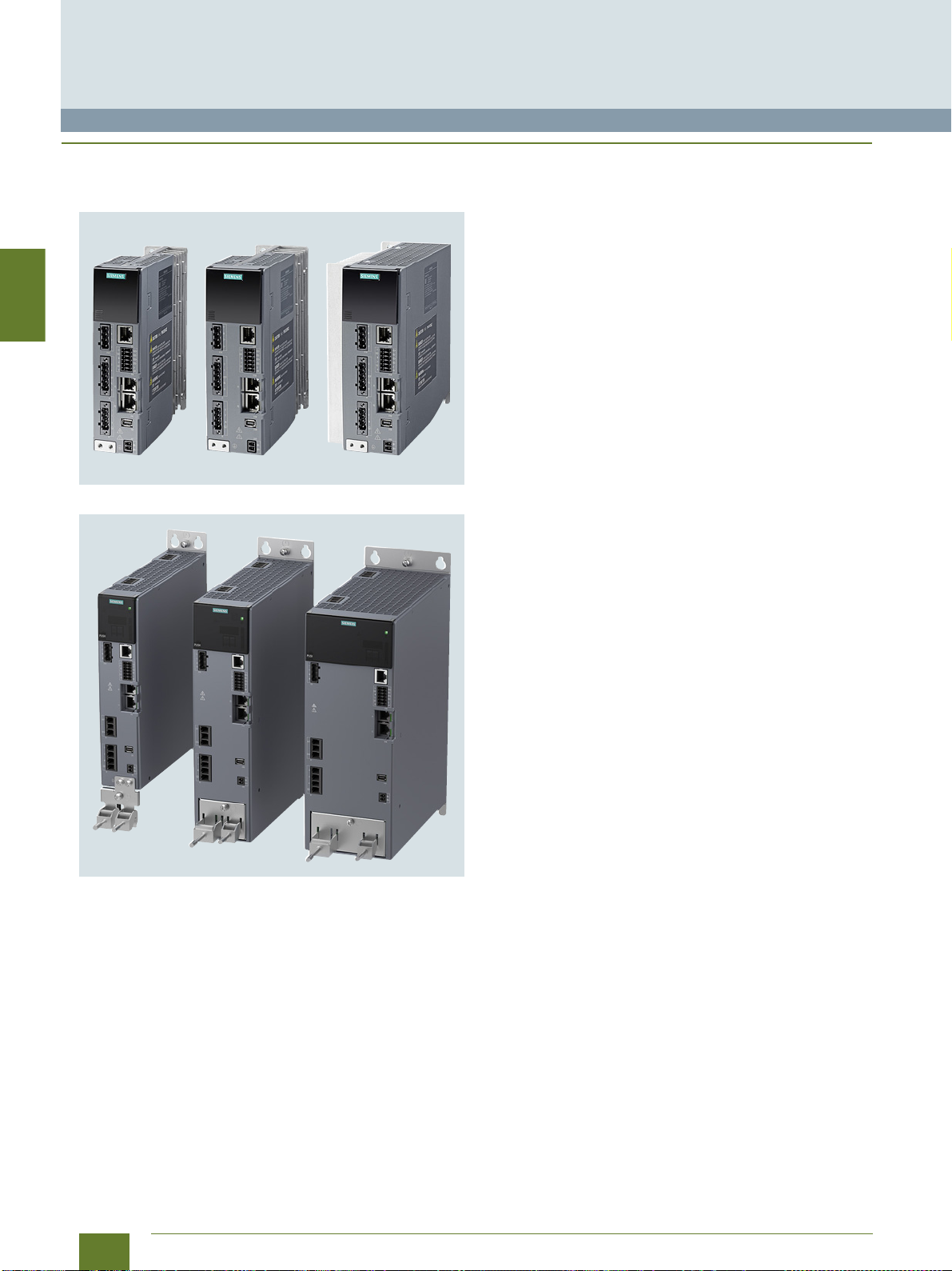
2
SINAMICS S210 servo drive
0.1 kW to 7 kW
SINAMICS S210 servo drive
■
Overview
SINAMICS S210 – the single-axis servo drive
for highly dynamic applications
SINAMICS S210, 1 AC series, frame sizes FSA to FSC
SINAMICS S210, 3 AC series, frame sizes FSA to FSC
The SINAMICS S210 servo converter is designed for
connection to SIMOTICS S-1FK2 synchronous servomotors.
PROFINET RT/IRT is available for connection to a higher-level
control system. That allows, above all, SIMATIC S7 and
SIMOTION to be used as controllers.
SINAMICS S210 is optimized for operation with
SIMATIC S7-1500 and SIMATIC S7-1500T, which have their own
positioning functionality. Therefore no additional basic positioner
is integrated into the converter.
The converter works with a servo controller with or without
Dynamic Servo Control (DSC) and has a torque setpoint
limitation. A wide range of internal protection functions are
included to protect the converter.
The status of the converter is indicated by two multi-color LEDs
and a 7-segment display. Pending faults can be acknowledged
with a button under the front cover.
© Siemens 2020
The converter has a web server, which can be called via the
service interface or via PROFINET from a web browser on a PC.
Both commissioning and diagnostics can be performed through
this. With the web server, the converter can be brought into
operation in a few steps. As the motor data from the converter is
read from the electronic type plate, they do not need to be
parameterized. The PROFIdrive telegram is automatically
accepted by the controller; so only the controller parameters
have to be adjusted. This is simply done with the One Button
Tuning function, which automatically determines the parameters.
In addition to easy commissioning directly via the web server
of the converter, engineering is also possible with SINAMICS
Startdrive and TIA Portal (as of V15.1). The tool for configuration,
commissioning and diagnostics has been optimized with regard
to user friendliness and the consistent utilization of the TIA Portal
advantages of a shared work environment for PLC, HMI and
drives (requires SINAMICS S210 firmware V5.2 or higher).
SIMOTICS S-1FK2 servomotors can be connected and operated via a One Cable Connection (OCC) line. Third-party motors
cannot be connected because the converter requires the type
plate data of the motor.
No additional components are required for controlling the motor
holding brake as all the required components are integrated into
the converter. In addition, no special power supply is required
because the converter optimally sets the voltage for the brake
internally. Thus, in combination with the 1FK2 motors, shortened
opening and closing times of the brakes are also possible.
The converter can be operated optionally with a memory card.
The card is inserted in the card slot behind the front cover. Firmware and drive parameters can be stored on the memory card,
so that the converter can easily be replaced without any other
aids. This memory card can also be used to perform series commissioning on multiple drives of identical type.
The card is available as an empty memory card or containing the
latest drive firmware version. The memory card also contains the
licenses for chargeable functions, such as the safety license
for the Extended Safety Functions. To use these functions, a
memory card containing the corresponding safety license must
be permanently inserted.
If necessary, the converter contains an integrated braking resistor. As a result of the generous dimensioning of the resistor and
the DC link capacities, an external braking resistor is only
necessary to meet very high requirements. When operating a
SINAMICS S210 servo converter with a supply voltage of 200 V
to 240 V 3 AC, an external, intrinsically safe braking resistor is
always required.
For the 3 AC series, DC link coupling of up to six devices is possible. Thus, the energy that is generated when braking axes can
be used for accelerating other axes. This conserves energy and
reduces the amount of heat dissipated via the braking resistors.
The converter also features an integrated line filter.
For the 1 AC series, it satisfies category C2 for cable lengths
up to 10 m and category C3 for cable lengths up to 25 m. With
an optional external line filter, cable lengths of up to 25 m are
also possible with category C2 and up to 50 m with category C3.
For the 3 AC series, category C3 is achieved for cable lengths
up to 25 m. For requirements that go beyond this, an external
line filter is required.
2/2
Siemens D 32 · January 2020
Change 07/2020
Page 31

2
■
To further PROFINET devices
(e.g. further SINAMICS S210)
OCC (One Cable Connection for motor,
motor holding brake and encoder)
SIMOTICS S-1FK2
servomotor
Controller
(e.g. SIMATIC S7-1500)
Commissioning device
SINAMICS S210
converter
1 AC series
Power supply
24 V DC
Braking resistor
(optional)
Line filter
(optional)
Fuse or
circuit-breaker
PROFINET
To further PROFINET devices
(e.g. further SINAMICS S210)
OCC (One Cable Connection for motor,
motor holding brake and encoder)
SIMOTICS S-1FK2
servomotor
DC link coupling
(optional)
Controller
(e.g. SIMATIC S7-1500)
Commissioning device
SINAMICS S210
converter
3 AC series
Power supply
24 V DC
Braking resistor
(optional)
Line filter
(optional)
Fuse or
circuit-breaker
PROFINET
Overview
© Siemens 2020
SINAMICS S210 servo drive
0.1 kW to 7 kW
SINAMICS S210 servo drive
SINAMICS S210 drive system, 1 AC series with optional components
SINAMICS S210 drive system, 3 AC series with optional components
Siemens D 32 · January 2020
2/3
Page 32

2
SINAMICS S210 servo drive
G_D211_XX_00462
0.1 kW to 7 kW
SINAMICS S210 servo drive
■
Design
The single-axis AC/AC converter contains a power unit and a
Control Unit for the powerful communication, open and closedloop control functions.
The SINAMICS S210 servo converter features the following
connections and interfaces as standard:
• Fieldbus interface
- 1 PROFINET interface with two ports (RJ45 sockets) with
PROFIdrive V4 profile
• 1 service interface for Ethernet communications with a
service PC
• One Cable Connection (OCC)
- 1 communications connector for communication with the
encoder of the SIMOTICS S-1FK2 motor
- 1 motor power connector for the power conductors of the
SIMOTICS S-1FK2 motor
- 1 brake connection for the conductors of the motor holding
brake of the SIMOTICS S-1FK2 motor
• 1 connection for the electronic power supply via the 24 V DC
supply connector (supply can be looped through connectors
for several SINAMICS S210)
• 1 connection for the line voltage and an external braking
resistor (braking resistor optional, for the 3 AC series via a
separate connector)
3 AC, an external, intrinsically safe braking resistor is always
required.
• 1 connection for the DC link coupling (optional, only for the
3AC series)
• Digital inputs
- 1 fail-safe digital input (isolated) for controlling STO and SS1
via terminals
- 2 high-speed digital inputs for measuring probe or reference
marks
- 1 digital input for monitoring the temperature of an external
braking resistor
• 1 slot for a memory card on which the firmware, parameters
and licenses can be stored
• 1 display with 3-digit, 7-segment display for indicating faults
and two status LEDs
• 1 button for acknowledging errors
. When connecting to 200 V to 240 V
© Siemens 2020
DC link coupling (only 3 AC series)
For devices of the 3 AC series, the DC links of up to six converters can be coupled. Thus, energy balancing between the axes
is possible and energy produced during braking can be used by
other axes for accelerating. This is not only efficient but also
reduces the dissipated heat in the control cabinet, because the
energy that is produced no longer has to be converted to heat in
the braking resistor. For DC link coupling, the line side must also
be coupled (AC bus).
SINAMICS S210, 3 AC series, one line filter plus five servo converters,
AC coupling and DC link coupling
2/4
Siemens D 32 · January 2020
Change 07/2020
Page 33

2
■
1)
Available in firmware V5.1 SP1 and higher. The Extended Functions require
a Safety license.
Function
Closed-loop control Servo control with DSC
Control functions
Protective functions
Safety Integrated
Commissioning Identification of the SIMOTICS S-1FK2 motors via
Speed control with encoder
Dynamic Servo Control (DSC)
Torque setpoint limitation
Current controller and current controller adapta-
tion suitably adjusted for SIMOTICS S-1FK2
servomotors
One Button Tuning with moment of inertia
estimator and reference model
Local measuring probe
Simple brake control
Direction reversal without changing the setpoint
channel
Travel to fixed stop
Vertical axis
Speed controller adaptation
Thermal monitoring for power unit and
servomotor
High-performance brake control
Undervoltage DC link voltage
Overvoltage DC link voltage
Overcurrent power unit
Overcurrent motor
Overload power unit (I
Short-circuit
Ground fault
Temperature rise servomotor
Temperature rise power unit
Safe Torque OFF (STO)
Safe Brake Control (SBC)
Safe Stop 1 (SS1)
Safe Stop 2 (SS2)
Safe Operating Stop (SOS)
Safely-Limited Speed (SLS)
Safe Speed Monitor (SSM)
Safe Direction (SDI)
Safely-Limited Acceleration (SLA)
Safe Brake Test (SBT) diagnostic function
the electronic type plate
Automatic controller optimization
2
t)
1)
1)
1)
1)
1)
1)
© Siemens 2020
■
Configuration
The following electronic configuring aids and engineering tools
are available for the SINAMICS S210 servo converters:
Drive Technology Configurator (DT Configurator) within
the CA 01
The Interactive Catalog CA 01 – the offline Industry Mall of
Siemens – contains over 100000 products with approximately
5 million possible drive system product variants. The Drive
Technology Configurator (DT Configurator) has been developed
to facilitate selection of the correct motor and/or converter from
the wide spectrum of drives. It is integrated as a selection tool in
the Interactive Catalog CA 01.
Online DT Configurator
In addition, the DT Configurator can be used on the Internet without requiring any installation. The DT Configurator can be found
in the Siemens Industry Mall at the following address:
www.siemens.com/dt-configurator
Drive dimensioning of the SINAMICS S210 servo drive
system with the TIA Selection Tool
The SINAMICS S210 servo drive system is easily configured with
the TIA Selection Tool under the Drive Dimensioning plug-in.
It provides support when selecting the hardware and firmware
components necessary to implement a drive task. The plug-in
encompasses the configuration of the entire drive system and
allows the handling of individual drives.
• Intuitive user interface, menu-based operation and help
• Configuration of the SINAMICS S210 servo drive system
• Adjustable traversing cycles and various mechanical systems
integrated for single-axis applications
• Interface to the TIA Portal and Industry Mall
The TIA Selection Tool is available for free on the Internet at
www.siemens.com/tia-selection-tool-standalone
Note:
Multi-axis applications and integration into the online version
available soon.
1)
SINAMICS web server for SINAMICS S210
The converter can be brought easily and quickly into operation
and optimized with the web server. Additional software does not
need to be installed as access comes directly from a web
browser.
You can find further information about the web server for
SINAMICS S210 in the Engineering tools section.
SINAMICS Startdrive commissioning tool (TIA Portal)
SINAMICS Startdrive is a tool for configuring, commissioning
and diagnosing the SINAMICS converter family that is integrated
into TIA Portal (V15.1 or higher).
The SINAMICS Startdrive has been optimized with regard to
user friendliness and consistent use of the TIA Portal benefits of
a common working environment for PLC, HMI and drives.
SINAMICS firmware V5.2 or higher is required for
SINAMICS S210.
The SINAMICS Startdrive Advanced license is required for the
Safety Integrated acceptance test.
The SINAMICS Startdrive commissioning tool is available free on
the Internet at
www.siemens.com/startdrive
You can find further information on the SINAMICS Startdrive
commissioning tool in the section Engineering tools.
SINAMICS S210 servo drive
0.1 kW to 7 kW
SINAMICS S210 servo drive
Change 07/2020
Siemens D 32 · January 2020
2/5
Page 34

2
SINAMICS S210 servo drive
Power
supply
N
L1
24 V
24 V
+
+
-
-
S
S
+ 24 V
+ 24 V
+ 24 V
DI 0
DI 1
L1
N
U
V
W
DCP
R2
R1
DI 2-
DI 3-
DI 4
DI 3+
DI 2+
BR-
BR+
M
M
ext.
24 V
M
M
T1 T2
l
lim
To n ex t
converter
Status display
via LED
Memory card
optional
Ethernet
Curr. sourcing
Curr. sinking
Fuse or circuit-bre aker
Internal
braking
resistor
PROFINET
PROFINET
Encoder
Motor holding brake
G_D211_EN_00380a
External braking
resistor (optional)
One Cable Connection
Line contactor
(optional)
Line filter
(optional)
Line
filter
0V
24V
X127
X130/1
X130/ 2
X150 P1
X150 P2
X10 0
X107
DI2
DI3
FDI
X124
X1
X2
M
E
0.1 kW to 7 kW
SINAMICS S210 servo drive
■
Integration
© Siemens 2020
Connection example SINAMICS S210 servo converter, 1 AC series
2/6
Siemens D 32 · January 2020
Change 07/2020
Page 35

2
■
Integration
© Siemens 2020
SINAMICS S210 servo drive
0.1 kW to 7 kW
SINAMICS S210 servo drive
Power
supply
M
L1 L2 L3
Fuse or
circuit-breaker
24 V
Line contactor
(optional)
Line filter
(optional)
To n ex t
converter
24 V
External braking
resistor (optional)
To n ex t
converter
(optional)
To n ex t
converter
M
24 V
ext.
24 V
M
X124
X1
X4
X3
X2
0V
24V
l
lim
L1
L2
L3
N
Relay
DCP
R2
R1
DCP
DCN
DC Link
U
V
W
G_D211_EN_00393a
T1 T2
Line
filter
Internal braking
resistor
DI2
FDI
DI3
PROFINET
PROFINET
Motor holding brake
Memory card optional
Ethernet
+ 24 V
DI 0
M
+ 24 V
DI 1
M
DI 2+
DI 2 DI 3+
DI 3-
+ 24 V
DI 4
Encoder
BR-
BR+
Status display
via LED
X127
X130/1
+
S
-
+
S
-
X130/ 2
Curr. sourcing
Curr. sinking
X150 P1
X150 P2
X10 0
X107
One Cable Connection
M
E
Connection example SINAMICS S210 servo converter, 3 AC series
Change 07/2020
Siemens D 32 · January 2020
2/7
Page 36

2
SINAMICS S210 servo drive
0.1 kW to 7 kW
SINAMICS S210 servo drive
■
Selection and ordering data
Description Frame
200 ... 240 V 1 AC
SINAMICS S210 servo converters
with shield plate and
push-in connectors
without memory card
The shield clamp is included in
the scope of delivery of the
MOTION-CONNECT cable.
• 0.1 kW FSA 6SL3210-5HB10-1UF0
• 0.2 kW FSA
size
Article No.
6SL3210-5HB10-2UF0
© Siemens 2020
Description Frame
200 ... 480 V 3 AC
SINAMICS S210 servo converters
with shield plate (for FSA only) and
push-in connectors
without memory card
The shield clamp is included in
the scope of delivery of the
MOTION-CONNECT cable.
size
• 0.4 kW FSA 6SL3210-5HE10-4UF0
•0.75kW FSA
• 1 kW FSA 6SL3210-5HE11-0UF0
Article No.
6SL3210-5HE10-8UF0
• 0.4 kW FSB
•0.75kW FSC
6SL3210-5HB10-4UF0
6SL3210-5HB10-8UF0
• 1.5 kW FSB
• 2 kW FSB 6SL3210-5HE12-0UF0
• 3.5 kW FSC
• 5 kW FSC
• 7 kW FSC 6SL3210-5HE17-0UF0
6SL3210-5HE11-5UF0
6SL3210-5HE13-5UF0
6SL3210-5HE15-0UF0
When operating a SINAMICS S210 servo converter with a
supply voltage of 200 V to 240 V 3 AC, an external, intrinsically safe braking resistor is always required.
2/8
Siemens D 32 · January 2020
Change 07/2020
Page 37

2
■
1)
Extended function for an existing memory card (firmware V5.1 SP1 or
higher). The memory card is not included in the scope of delivery.
The Safety license can also be ordered together with a memory card
(see above). With a CoL in electronic form, the license is supplied as a
PDF file. Notification of this with a download link is received by email.
For further information, see section Supplementary system components >
Memory cards.
2)
The data is applicable for the complete cable length of the motors, whose
associated converters are coupled with one another via an AC coupling or
through the DC link.
The maximum cable length per motor is 25 m using the internal filters or an
external filter to achieve EMC category C2. If an external filter is used to
achieve EMC category C3, the maximum cable length per motor is 50 m.
3)
Permissible cables:
-16mm
2
, Class 5 (finely stranded, PVC-insulated) H07V-K + H07V2-K
according to EN 50525-2-31
- HELUTHERM 145: 16 mm
2
, Class 5 (finely stranded, crosslinked
polyolefin-copolymer, halogen-free)
www.helukabel.com
- External diameter 6.7 mm to 8.1 mm
Permissible cables (UL approval):
- AWG 6, copper cable with PVC insulation, with or without nylon jacket,
19 strands
- Types: MTW, THHW, THW, THW-2, THHN, THWN-2, TW, TWN
- CSA types: TW, TWU, TWN75, TW75, TWU75, T90, no compressed
conductors
Selection and ordering data
Accessories
Description Article No.
SINAMICS SD card
(optional)
512 MB
The parameter
assignment, firmware
and licenses for a
converter can be
stored on this
memory card.
Firmware V5.2 or
higher is required for
the 3 AC series.
•Empty 6SL3054-4AG00-2AA0
• With firmware V5.1
• With firmware V5.1 SP1
• With firmware V5.1 SP1
and Safety license
(Extended Functions)
• With firmware V5.2
• With firmware V5.2
and Safety license
(Extended Functions)
• With firmware
V5.2 SP3
• With firmware
V5.2 SP3
and Safety license
(Extended
Functions)
Safety license
(Extended Functions)
• CoL in paper form 6SL3074-0AA10-0AA0
• CoL in electronic
PROFINET patch cable
For the networking of
concatenated converters
Industrial Ethernet
TP cord, CAT 6 A,
twisted pair line
4 × 2 cores,
pre-assembled with
two RJ45 connectors
• 0.3 m (0.98 ft) 6XV1870-3QE30
• 0.5 m (1.64 ft)
Only for the 1 AC series
Line filter 6SL3203-0BB21-8VA1
With this line filter,
Category C2 for
cable lengths up to
25 m (82 ft),
Category C3 for
cable lengths up to
50 m (164 ft) acc. to
EN 61800-3 can be
achieved.
Replacement
connector set
For frame sizes FSA, FSB
and FSC
With a connector set, as in
the scope of delivery, and
two shield plates
form
1)
© Siemens 2020
6SL3054-4FB00-2BA0
6SL3054-4FB10-2BA0
6SL3054-4FB10-2BA0-Z
F01
6SL3054-4FC00-2BA0
6SL3054-4FC00-2BA0-Z
F01
6SL3054-4FC30-2BA0
6SL3054-4FC30-2BA0-Z
F01
6SL3074-0AA10-0AH0
6XV1870-3QE50
6SL3260-2DB00-0AA0
SINAMICS S210 servo drive
0.1 kW to 7 kW
SINAMICS S210 servo drive
Description Article No.
Only for the 3 AC series
Line filter
With these line filters, Category C2 for cable lengths up
to 25 m (82 ft), Category C3
for cable lengths up to 50 m
(164 ft) acc. to IEC 61800-3
can be achieved.
When connected via a
DC link, a total cable length
of up to 100 m (328 ft) with
Category C2 and up to
250 m (820 ft) with
Category C3 is possible
• ≤ 35 A 6SL3203-0BE23-5HA0
• ≤ 65 A
Connector set
AC bus and DC link
For coupling the DC link
and the line infeed
Scope of delivery: 1 AC bus
connector, 1 DC link
connector, 2 cover caps
The AC bus connector
replaces the push-in
connector included in the
scope of delivery of the
converter.
Wiring is performed with
conventional 16 mm
(not included in scope of
3)
delivery)
Connector set
AC bus individual
For coupling the line infeed
Scope of delivery: 1 AC bus
connector, 1 cover cap
This connector replaces the
push-in connector included
in the scope of delivery of
the converter. Wiring is performed with conventional
2
16 mm
cable (not included
in scope of delivery)
External braking resistors
for 200 … 240 V 3 AC
For a supply voltage
of 200 V to 240 V 3 AC, an
external, intrinsically safe
braking resistor is always
required for each converter
• 100 W, 47 Ω for
FSA and FSB
• 240 W, 14Ω for FSC
Replacement connector set
For frame sizes FSA, FSB
and FSC
With a connector set, as in
the scope of delivery, and
one shield plate (for FSA)
Replacement fan
Incl. support
• Frame size FSA 6SL3260-0AA00-0AA0
• Frame size FSB
• Frame size FSC
2)
6SL3203-0BE26-5HA0
6SL3260-2DC00-0AA0
2
cable
6SL3260-2DC10-0AA0
3)
GXK:BWG250047TS-190
GXK:BWG600014TS-190
6SL3260-2DB10-0AA0
6SL3260-0AB00-0AA0
6SL3260-0AC00-0AA0
Change 07/2020
Siemens D 32 · January 2020
2/9
Page 38

2
1)
In transport packaging.
2)
In product packaging.
© Siemens 2020
SINAMICS S210 servo drive
0.1 kW to 7 kW
SINAMICS S210 servo drive
■
Technical specifications
Unless explicitly specified otherwise, the following technical specifications are valid for all SINAMICS S210 servo converters.
General technical specifications
Mechanical specifications
Vibratory load
• Transport1) acc. to IEC 60721-3-2: 1997 Class 2M3
• Operation acc. to IEC 60721-3-3: 2002
- Test values according to IEC/EN 60068-2-6
Shock load
• Transport1) acc. to IEC 60721-3-2: 1997 Class 2M3
• Operation acc. to IEC 60721-3-3: 2002
- Test values according to IEC/EN 60068-2-27
Environmental conditions
Protection class
According to IEC/EN 61800-5-1
Degree of protection
According to IEC/EN 60529
Permissible ambient temperature (air) in operation
Installation altitude
Climatic environmental conditions
•Storage2) acc. to IEC 60721-3-1: 1997 Class 1K4
1)
• Transport
• Operation acc. to IEC 60721-3-3: 2002
Environmental class/harmful chemical substances
•Storage2) acc. to IEC 60721-3-1: 1997 Class 1C2
• Transport
• Operation acc. to IEC 60721-3-3: 2002
Organic/biological influences
•Storage2) acc. to IEC 60721-3-1: 1997 Class 1B2
• Transport
• Operation acc. to IEC 60721-3-3: 2002
Degree of pollution
According to IEC/EN 61800-5-1
Standards
Certificates of suitability CE, cULus (UL File No. E355661 for 1 AC series, E192450 for 3 AC series),
Functional safety
acc. to IEC 60721-3-2: 1997 Class 2K4
1)
acc. to IEC 60721-3-2: 1997 Class 2C2
1)
acc. to IEC 60721-3-2: 1997 Class 2B2
Class 3M2
Test Fc (sinusoidal)
• 9 ... 18 Hz: 1.5 mm deflection amplitude
•18Hz...200Hz: 2×g acceleration amplitude
• 10 frequency cycles per axis
Class 3M2
Test Ea (semisinusoidal)
•5×g peak acceleration
•30ms duration
• 3 shocks in all three axes in both directions
Class I (with protective bonding circuit) and class III (PELV or SELV)
IP20
Mounting in control cabinet necessary
0...50°C (32...122°F)
Up to max. 4000 m (13123 ft) (IEC/EN/UL), up to max. 2000 m (6562 ft) (CSA)
• Up to 1000 m (3281 ft) above sea level without derating
• As from 1000 m (3281 ft) derating 10 % of current or 5 K per 1000 m (3281 ft)
• For 1 AC devices, an isolating transformer is required from 2000 m (6562 ft)
-25 ... +55 °C (-13 ... +131 °F)
-40 ... +70 °C (-40 ... +158 °F)
Max. air humidity: 95 % at 40 °C (104 °F)
Better than class 3K3
0...50°C (32...122°F)
Relative air humidity: 5 ... 95 %
Condensation, splashwater, and ice formation not permitted
(IEC/EN 60204, Part 1)
Class 3C2
Class 3B2
2
RCM, EAC, KC (only for 1 AC series, available soon for 3 AC series)
• SIL 2 according to IEC 61508 parts 1 to 3 (2010) and IEC 61800-5-2 (2016)
• PL d according to ISO 13849 part 1 (2015)
• Category 3 according to IEC 60204 (2007)
2/10
Siemens D 32 · January 2020
Page 39

2
1)
An internal braking resistor is not required for normal operation on account
of the available DC link capacity.
2)
The specified delay times refer to the hardware. The actual reaction time
depends on the time slot in which the digital input is processed.
© Siemens 2020
SINAMICS S210 servo drive
SINAMICS S210 servo drive
■
Technical specifications
Line voltage 200 ... 240 V 1 AC SINAMICS S210 servo converters, 1 AC series
6SL3210-5HB10-1UF0 6SL3210-5HB10-2UF0 6SL3210-5HB10-4UF0 6SL3210-5HB10-8UF0
Line supply connection
• Supply voltage 200 ... 240 V 1 AC ±10 %
• Line frequency
• Conductor cross-section, max.
• Line system configuration
Rated current A 1.4 2.7 5 9.3
Inrush current
Power loss W 15.7 23.2 38.5 71.1
Electronic power supply
•Voltage 24 V -15 % ... +20 %
• Power requirement, max.
• Conductor cross-section, max. mm
Output
• Rated power 230 V kW 0.1 0.2 0.4 0.75
• Rated current
• Output current, max.
Pulse frequency power unit
Output frequency Hz 0...550
Line filter
Braking resistor Without
Digital inputs
• Fast inputs for measuring
probes, reference marks, temperature monitoring, external
braking resistor
-Low level
- High level
- Current consumption
- Delay time, typ., L → H
- Delay time, typ., H → L
- Galvanic isolation
• Fail-safe input
-Low level
- High level
- Current consumption
- Delay time, typ., L → H
- Delay time, typ., H → L
- Galvanic isolation
• Conductor cross-section, max.
Cooling
Frame size FSA FSB FSC
Dimensions
•Width mm (in) 45 (1.77) 55 (2.17) 74.5 (2.93)
•Height
•Depth
Weight, approx.
2)
Hz 50/60
mm22.5
A 8 8 8 8
A 0.8 without brake
A 0.8 1.4 2.4 4.4
A 3.1 4.8 8.7 16
kHz 8
mA 6
μs 5
μs 50
mA 5
μs 50
μs 100
mm21.5
mm (in) 170 (6.69) 170 (6.69) 170 (6.69)
mm (in) 170 (6.69) 170 (6.69) 195 (7.68)
kg (lb) 1.1 (2.43) 1.2 (2.65) 1.9 (4.19)
Grounded TN/TT networks and ungrounded IT networks
For current consumption of the brake, see section SIMOTICS S-1FK2 servomotors > Technical specifications >
Holding brake, page 3/10
2
2.5
Integrated, category C2 (up to 10 m (32.8 ft) cable length), category C3 (up to 25 m (82.0 ft) cable length)
1)
3
-30V...+5V and ≤ 2mA
15 V... 30 V
No
1
-30V...+5V and ≤ 2mA
15 V... 30 V
Yes
Convection (without fan)
Integrated Integrated Integrated
0.1 kW to 7 kW
Change 07/2020
Siemens D 32 · January 2020
2/11
Page 40

2
1)
The specified delay times refer to the hardware. The actual reaction time
depends on the time slot in which the digital input is processed.
© Siemens 2020
SINAMICS S210 servo drive
0.1 kW to 7 kW
SINAMICS S210 servo drive
■
Technical specifications
Line voltage 200 ... 480 V 3 AC SINAMICS S210 servo converters, 3 AC series
6SL32105HE10-4UF0
Line supply connection
• Supply voltage 200 ... 480 V 3 AC ±10 %
• Line frequency
• Conductor cross-section, max.
• Line system configuration
Rated current
Inrush current
Power loss W 69 81 94 114 131 167 191 204
Electronic power supply
•Voltage 24 V -15 % ... +20 %
• Power requirement, max.
• Conductor cross-section, max. mm
Output
• Rated power
-400V kW 0.4 0.75 1 1.5 2 3.5 5 7
-240V
• Rated current
• Output current, max.
Pulse frequency power unit
Output frequency Hz 0...550
Line filter
Braking resistor Integrated, when connecting to 200 V... 240 V 3 AC, an external, intrinsically safe braking resistor is always
Digital inputs
• Fast inputs for measuring
probes, reference marks, temperature monitoring, external
braking resistor
-Low level
- High level
- Current consumption
- Delay time, typ., L → H
- Delay time, typ., H → L
- Galvanic isolation
• Fail-safe input
-Low level
- High level
- Current consumption
- Delay time, typ., L → H
- Delay time, typ., H → L
- Galvanic isolation
• Conductor cross-section, max.
Cooling
Frame size FSA FSB FSC
Dimensions
•Width mm (in) 50 (1.97) 70 (2.76) 105 (4.13)
•Height mm (in) 231 (9.09) 280 (11.0) 280 (11.0)
•Depth mm (in) 223 (8.78) 223 (8.78) 223 (8.78)
Weight, approx. kg (lb) 2.1 (4.63) 3.3 (7.28) 5 (11.03)
1)
Hz 50/60
mm26
A 1.6 2.8 3.8 6 7.5 12.5 15 17.9
A 4.3 4.3 4.3 8.6 8.6 27.8 27.8 27.8
A 1.2 without brake
kW 0.24 0.45 0.6 0.9 1.2 2.1 3 4.2
A 1.2 2.3 3 5 7 9 12 15
A 4.2 7.6 10.9 19 24 33 44 55
kHz 8
mA 6
μs 5
μs 50
mA 5
μs 50
μs 100
mm21.5
Grounded TN/TT networks, ungrounded IT networks and networks with grounded line conductor only with an
isolating transformer
For current consumption of the brake, see section SIMOTICS S-1FK2 servomotors > Technical specifications >
Holding brake, page 3/10
2
2.5
Category C3 (up to 25 m (82.0 ft) cable length for a single axis, for DC link coupling see Accessories/line filters)
required.
3
-30V...+5V and ≤ 2mA
15 V... 30 V
No
1
-30V...+5V and ≤ 2mA
15 V... 30 V
Yes
Air cooling with integrated fan
6SL32105HE10-8UF0
6SL32105HE11-0UF0
6SL32105HE11-5UF0
6SL32105HE12-0UF0
6SL32105HE13-5UF0
6SL32105HE15-0UF0
6SL32105HE17-0UF0
2/12
Siemens D 32 · January 2020
Change 07/2020
Page 41

2
■
172.4 (6.79) (2.17)55
G_D011_EN_00550
(0.24)
6
(6.22)
158
(8.62)219
(6.69)
170
(0.33)
(1.5 )
38
8.5
2 × Ø 5.6 (0.22)
Drill pattern
G_D011_EN_00585
(8.77) (1.18)
(0.24)
222.8
(11.8)299.6
(9.09)231
(10. 24)260
(0.29)7. 2
(1.97)50 30
6
(0.23)5.9
Dimensional drawings
172.4 (6.79)
© Siemens 2020
SINAMICS S210 servo drive
0.1 kW to 7 kW
SINAMICS S210 servo drive
(1.1)28
(1.77)45
(0.24)6(6.22)158
8.5
(0.33)
(6.69)
170
(8.62)219
G_D011_EN_00549
2 × Ø 5.6 (0.22)
Drill pattern
Dimensional drawing SINAMICS S210, frame size FSA, 1 AC series
Dimensional drawing SINAMICS S210, frame size FSB, 1 AC series
(2.26)
57.5
197.4 (7.77) (2.93) (0.33)
74. 5
(0.24)(6.22)
6
8.5
Dimensional drawing SINAMICS S210, frame size FSA, 3 AC series
(8.77)222.8
(11.02)280
(2.76)70
(12. 68)322
(1.97)50
(0.24)6
(0.28)7. 2
(12.17)309
Dimensional drawing SINAMICS S210, frame size FSC, 1 AC series
All dimensions in mm (values in brackets are in inches).
With the OCC motor connection cable connected, the overall
depth increases by 56.6 mm
(6.69)
170
(8.62)
219
(2.28 inches).
158
3 × Ø 5.6
Drill pattern
G_D011_EN_00548a
(0.22)
Change 07/2020
G_D011_EN_00586a
(0.4)10.1
50
(1.97)
Dimensional drawing SINAMICS S210, frame size FSB, 3 AC series
(8.77)222.8
(11.02)280
(12. 68)322
12.4 5
(4.13)105 (3.15)80
(0.49)
(0.22)
5.5
G_D011_EN_00587
(3.15)80
Dimensional drawing SINAMICS S210, frame size FSC, 3 AC series
Siemens D 32 · January 2020
2/13
(0.29)
7. 3
(12.17)309
Page 42

2
SINAMICS S210 servo drive
1)
The data is applicable for the complete cable length of the motors, whose
associated converters are coupled with one another via an AC coupling or
through the DC link.
The maximum cable length per motor is 25 m using the internal filters or an
external filter to achieve EMC category C2. If an external filter is used to
achieve EMC category C3, the maximum cable length per motor is 50 m.
0.1 kW to 7 kW
SINAMICS S210 servo drive
■
Accessories
Line filters
1 AC series
Filters are already integrated in order to achieve category C2
(for motor cable lengths up to 10 m) or category C3 (for motor
cable lengths up to 25 m). Further requirements can be
achieved using an external line filter.
1 AC series Maximum motor cable length
for converters without
additional line filter
EMC category C2
EMC category C3
10 m (32.8 ft) 25 m (82.0 ft)
25 m (82.0 ft) 50 m (164 ft)
3 AC series
Filters for achieving category C3 are already integrated (for
motor cable lengths up to 25 m). Further requirements can be
achieved using an external line filter.
3 AC series Line/DC link
EMC category C2
EMC category C3
coupling
Without
line/DC link
coupling
With
line/DC link
coupling
≤ 6 converters
Without
line/DC link
coupling
With
line/DC link
coupling
≤ 6 converters
1)
1)
for converters with
external line filter
Maximum motor cable length
for converters
with integrated
line filter
– 25 m (82 ft)
– 100 m (328 ft)
25 m (82 ft) 50 m (164 ft)
100 m (328 ft) 250 m (820 ft)
for converters
with external
line filter
© Siemens 2020
Recommended line-side overcurrent protection devices
Overcurrent protection devices are absolutely necessary for
the operation of the converters. The table listed in the section
"Recommended line-side overcurrent protection devices"
provides recommendations according to IEC and UL regulations, depending on the area of application. Recommendations
on further overcurrent protection devices are available at:
https://support.industry.siemens.com/cs/document/109748999
Additional information about the listed Siemens fuses is
available in Catalog LV 10 as well as in the Industry Mall.
Braking resistors
As far as necessary, braking resistors are integrated into the
converters. Together with the generously dimensioned DC link
capacities, an external braking resistor is not necessary in the
normal case.
If the internal braking resistor is inadequate for applications with
very high requirements, an external braking resistor can be
connected as an alternative. When operating a SINAMICS S210
servo converter with a supply voltage of 200 V to 240 V 3 AC, an
external, intrinsically safe braking resistor is always required.
Memory cards
A memory card (SINAMICS SD card) can be optionally used with
SINAMICS S210. The associated slot is located under the front
cover of the converter. Not only the firmware but also the device
parameterization of a SINAMICS S210 servo converter can be
stored on the memory card.
When service is required, e.g. after the converter has been
replaced and the data have been downloaded from the memory
card, the drive system is immediately ready for use again.
A memory card is only absolutely necessary if functions requiring license, such as the Extended Safety Functions, are used.
The necessary license is saved on the memory card.
Example: SINAMICS S210, 3 AC line filter with servo converter, frame size FSB
2/14
Siemens D 32 · January 2020
Change 07/2020
Page 43

2
■
Overview
1 AC line filter, 18 A
© Siemens 2020
■
Technical specifications
Line voltage
200 ... 240 V 1 AC
Rated current A 18
Power loss W < 1.2
Line/load
connection
• Conductor
cross-section
- For single-
conductor
connection
- For flexible
cables
PE connection
Degree of
protection
Dimensions
•Width mm (in) 62 (2.44)
•Height
•Depth
Weight, approx.
Suitable for
SINAMICS S210
servo converter
SINAMICS S210 servo drive
0.1 kW to 7 kW
Line-side components > Line filters
Line filter
6SL3203-0BB21-8VA1
Screw terminals
mm20.25 ... 6
AWG 24 ... 10
mm20.25 ... 4
AWG 24 ... 12
M5 screw stud
IP20
mm (in) 155 (6.10)
mm (in) 53 (2.09)
kg (lb) 0.7 (1.54)
Typ e 6SL3210-5HB10-1UF0 (1.4 A)
6SL3210-5HB10-2UF0 (2.7 A)
6SL3210-5HB10-4UF0 (5 A)
6SL3210-5HB10-8UF0 (9.3 A)
3 AC line filter, 35 A and 65 A
The line filters are connected via the AC coupling of the
converters.
The total of the rated currents of the converters on an AC bus
must not exceed the rated current of the line filter.
■
Selection and ordering data
Rated current of
the servo converter
A Article No.
Line voltage 200 ... 240 V 1 AC
1.4 6SL3210-5HB10-1UF0 6SL3203-0BB21-8VA1
2.7 6SL3210-5HB10-2UF0
5 6SL3210-5HB10-4UF0
9.3 6SL3210-5HB10-8UF0
Line voltage 200 ... 480 V 3 AC
1.6 6SL3210-5HE10-4UF0
2.8 6SL3210-5HE10-8UF0
3.8 6SL3210-5HE11-0UF0
6 6SL3210-5HE11-5UF0
7.5 6SL3210-5HE12-0UF0
12.5 6SL3210-5HE13-5UF0
15 6SL3210-5HE15-0UF0
17.9 6SL3210-5HE17-0UF0
• Total of the currents ≤ 35 A 6SL3203-0BE23-5HA0
• Total of the currents ≤ 65 A
Suitable for
SINAMICS S210
Line filter
6SL3203-0BE26-5HA0
Line voltage
200 ... 480 V 3 AC
Rated current
Power loss W 12 18
Line supply
connection
• Conductor
cross-section
Load connection
• Conductor
cross-section
PE connection
Degree of
protection
Dimensions
•Width mm (in) 50 (1.97) 70 (2.76)
•Height
•Depth
Weight, approx. kg (lb) 2.3 (5.07) 3.5 (7.72)
Suitable for
SINAMICS S210
servo converter
Line filter
6SL3203-0BE23-5HA0 6SL3203-0BE26-5HA0
A 35 65
Screw terminals Screw terminals
mm20.5 ... 10
AWG 24 ... 6
Screw terminals Screw terminals
mm216
AWG 6
M4 screw stud M5 screw stud
IP20 IP20
mm (in) 296.2 (11.66) 348.8 (13.73)
mm (in) 220 (8.66) 220 (8.66)
Typ e 6SL3210-5HE10-4UF0 (1.6 A)
6SL3210-5HE10-8UF0 (2.8 A)
6SL3210-5HE11-0UF0 (3.8 A)
6SL3210-5HE11-5UF0 (6 A)
6SL3210-5HE12-0UF0 (7.5 A)
6SL3210-5HE13-5UF0 (12.5 A)
6SL3210-5HE15-0UF0 (15 A)
6SL3210-5HE17-0UF0 (17.9 A)
4 ... 25
AWG 10 ... 3
16
AWG 6
Change 07/2020
Siemens D 32 · January 2020
2/15
Page 44

2
© Siemens 2020
SINAMICS S210 servo drive
0.1 kW to 7 kW
Line-side components > Recommended line-side overcurrent protection devices
■
Selection and ordering data
Overcurrent protection devices are absolutely necessary for the
operation of the converters. The following table lists recommendations for fuses.
• Siemens fuses of type 3NA3 for use in the area of validity of IEC
• UL-listed fuses Class J for use in USA and Canada
Recommendations on further overcurrent protection devices are
available at:
https://support.industry.siemens.com/cs/document/109748999
The Short Circuit Current Rating (SCCR) according to UL for
industrial control cabinet installations to NEC Article 409 or
UL 508A/508C or UL 61800-5-1 is as follows for Class J fuses for
• SINAMICS S210: 65 kA
SCCR and ICC values for combination with further overcurrent
protection devices are available at:
https://support.industry.siemens.com/cs/document/109748999
Rated power SINAMICS S210 IEC-compliant UL/cUL-compliant
Fuse Fuse type
Current 3NA3 Current
kW Ty pe A Article No. Class A
Line voltage 200 ... 240 V 1 AC
0.1 6SL3210-5HB10-1UF0 6 3NA3801 J6
0.2 6SL3210-5HB10-2UF0 6
0.4 6SL3210-5HB10-4UF0 10
0.75 6SL3210-5HB10-8UF0 16
Line voltage 200 ... 480 V 3 AC
0.4 6SL3210-5HE10-4UF0 16 3NA3805 J15
0.75 6SL3210-5HE10-8UF0 16
1 6SL3210-5HE11-0UF0 16
1.5 6SL3210-5HE11-5UF0 32
2 6SL3210-5HE12-0UF0 32
3.5 6SL3210-5HE13-5UF0 63
5 6SL3210-5HE15-0UF0 63
7 6SL3210-5HE17-0UF0 63
Group protection of multiple converters
Further information is available in the technical documentation
on the Internet at:
www.siemens.com/sinamics-s210/documentation
https://support.industry.siemens.com/cs/document/109748999
Notes for installations in Canada:
The converters are intended for line supply systems with
overvoltage category III.
More information is available in the technical documentation on
the Internet at:
www.siemens.com/sinamics-s210/documentation
Additional information about the listed Siemens fuses is avail-
able in Catalog LV 10 as well as in the Industry Mall.
Rated voltage 600 V AC
3NA3801 J6
3NA3803 J10
3NA3805 J20
3NA3805 J15
3NA3805 J15
3NA3812 J30
3NA3812 J30
3NA3822 J70
3NA3822 J70
3NA3822 J70
2/16
Siemens D 32 · January 2020
Page 45

2
■
Overview
As far as necessary, braking resistors are integrated into the
converters. Together with the generously dimensioned DC link
capacities, another external braking resistor is not necessary in
the normal case.
If the internal braking resistor is inadequate for applications with
very high requirements, an external braking resistor can be connected as an alternative.
Only intrinsically safe braking resistors with temperature monitoring may be used in order to minimize the risk of an explosion,
the outbreak of fire or melting of the enclosure in the event of a
continuous overload, e.g. due to a defect.
External braking resistors for 200 V to 240 V 3 AC
For operation with a supply voltage of 200 V to 240 V 3 AC, an
external, intrinsically safe braking resistor is always required for
each converter. Use of braking resistors integrated in the converter is not permissible with this supply voltage.
The following resistors are recommended as a substitute for the
internal braking resistors. If these are not sufficient, the resistors
from Michael Koch GmbH listed in the table can be used.
• 100 W, 47 Ω for frame sizes FSA and FSB:
GXK:BWG250047TS-190
• 240 W, 14 Ω for frame size FSC:
GXK:BWG600014TS-190
These resistors have approvals for the North American market
(cURus and CSA).
If the temperature sensor of the resistor is connected to the input
DI4 of the converter, the converter switches off when the braking
resistor is overloaded.
■
More Information
Further information is available from the "Siemens Product
Partner for Drives Options":
www.siemens.com/drives-options-partner
© Siemens 2020
■
Technical specifications
Requirements placed on an external braking resistor
Converter Braking resistor
Article No. Rated
6SL3210-... kW Ω W W kJ
Line voltage 200...240V1AC
5HB10-1UF0 0.1 300 50 350 0.7
5HB10-2UF0 0.2 150 100 600 1.3
5HB10-4UF0 0.4 100 200 1300 2.3
5HB10-8UF0 0.75 50 380 2400 3.8
Line voltage 200...240V3AC
5HE10-4UF0 0.4 100 200 600 1
5HE10-8UF0 0.75 100 380 1200 1
5HE11-0UF0 1 100 500 1700 1
5HE11-5UF0 1.5 50 880 2900 20
5HE12-0UF0 2 50 1000 3800 20
5HE13-5UF0 3.5 15 1750 7500 25
5HE15-0UF0 5 15 2500 9500 25
5HE17-0UF0 7 15 3250 12500 25
Line voltage 380...480V3AC
5HE10-4UF0 0.4 200 200 1200 8
5HE10-8UF0 0.75 200 380 2400 8
5HE11-0UF0 1 200 500 3400 8
5HE11-5UF0 1.5 100 880 5700 80
5HE12-0UF0 2 100 1000 7600 80
5HE13-5UF0 3.5 30 1750 15000 100
5HE15-0UF0 5 30 2500 19000 100
5HE17-0UF0 7 30 3250 25000 100
Examples of braking resistors from Michael Koch GmbH
Converter Braking resistors from Michael Koch GmbH
Article No. Order designation with
6SL3210-... W W W kJ
Line voltage 200...240V1AC
5HB10-1UF0 BWG250047TS-190 50 50 350 0.7
5HB10-2UF0 BWG250047TS-190 100 100 600 1.1
5HB10-4UF0 BWG250047TS-190 100 100 1300 1.8
5HB10-8UF0 BWG500027TS-190 200 200 2400 2.7
Line voltage 200...240V3AC
5HE10-4UF0 BWG500027TS-190 200 200 600 0.9
5HE10-8UF0 BWG600014TS-190 380 240 1200 0.8
5HE11-0UF0 BWG600014TS-190 400 240 1700 0.8
5HE11-5UF0 BWD500027K03LIP65IS 600 600 2900 14.5
5HE12-0UF0 BWD500027K03LIP65IS 600 600 3800 13.9
5HE13-5UF0 BWD600014K03LIP65IS 1200 720 7500 18.7
5HE15-0UF0 BWD600014K03LIP65IS 1200 720 9500 17.8
5HE17-0UF0 BWD600014K03LIP65IS 1200 720 12500 18.2
Line voltage 380...480V3AC
5HE10-4UF0 BWG500100TS-190 200 200 1200 5.2
5HE10-8UF0 BWG600047TS-190 380 240 2400 6.2
5HE11-0UF0 BWG600047TS-190 400 240 3400 6.1
5HE11-5UF0 BWD500100K03LIP65IS 600 600 5700 30.4
5HE12-0UF0 BWD500100K03LIP65IS 600 600 7600 30.4
5HE13-5UF0 BWD600047K03LIP65IS 1200 720 15000 50
5HE15-0UF0 BWD600047K03LIP65IS 1200 720 19000 47.5
5HE17-0UF0 BWD600047K03LIP65IS 1200 720 25000 41.7
SINAMICS S210 servo drive
0.1 kW to 7 kW
DC link components > External braking resistors
power
temperature sensor
190 °C
Min.
resistance
Max.
continuous
power
Continuous
power
for CE for UL
Max.
peak
power
Max.
peak
power
Max.
braking
energy
Max.
braking
energy
Change 07/2020
Siemens D 32 · January 2020
2/17
Page 46

2
SINAMICS S210 servo drive
1)
Extended function for an existing memory card (firmware V5.1 SP1 or
higher). The memory card is not included in the scope of delivery.
The Safety license can also be ordered together with a memory card
(see above). With a CoL in electronic form, the license is supplied as a
PDF file. Notification of this with a download link is received by email.
For further information to CoL in electronic form, see next page.
For further information to CoL, see section Software licenses.
0.1 kW to 7 kW
Supplementary system components > Memory cards
■
Overview
SINAMICS memory card (SD card)
The parameter assignment, firmware and licenses for a converter can be stored on the SINAMICS memory card (SD card).
When service is required, e.g. after the converter has been
replaced and the data have been downloaded from the memory
card the drive system is immediately ready for use again.
The memory card has the following functions:
• Parameter settings can be written from the memory card to the
converter or saved from the converter to the memory card
• The memory card supports series commissioning without the
use of a commissioning tool
• If firmware is stored on the memory card, the firmware can be
upgraded/downgraded during startup
• It is used for storing licenses when using functions under
license, e.g. the license for enabling the Extended Safety
Functions
- Safe Stop 2 (SS2)
- Safe Operating Stop (SOS)
- Safely-Limited Speed (SLS)
- Safe Speed Monitor (SSM)
- Safe Direction (SDI)
- Safely-Limited Acceleration (SLA)
- Safe Brake Test (SBT) diagnostic function
Notes:
In general, the converter can be operated without a memory
card. However, it is necessary if licenses, such as the Extended
Safety license, are required. The card must then remain permanently inserted.
Firmware V5.2 or higher is required for the 3 AC series or when
using the SINAMICS Startdrive commissioning tool.
© Siemens 2020
■
Selection and ordering data
Description Article No.
SINAMICS SD card
512 MB
Firmware V5.2 or higher is required for the
3AC series.
•Empty 6SL3054-4AG00-2AA0
• With firmware V5.1
• With firmware V5.1 SP1
• With firmware V5.1 SP1 and
Safety license (Extended Functions)
• With firmware V5.2
• With firmware V5.2 and
Safety license (Extended Functions)
• With firmware V5.2 SP3
• With firmware V5.2 SP3 and
Safety license (Extended Functions)
Safety license
(Extended Functions)
•CoL in paper form 6SL3074-0AA10-0AA0
• CoL in electronic form
6SL3054-4FB00-2BA0
6SL3054-4FB10-2BA0
6SL3054-4FB10-2BA0-Z
F01
6SL3054-4FC00-2BA0
6SL3054-4FC00-2BA0-Z
F01
6SL3054-4FC30-2BA0
6SL3054-4FC30-2BA0-Z
F01
1)
6SL3074-0AA10-0AH0
2/18
Siemens D 32 · January 2020
Change 07/2020
Page 47

2
■
„CoL“
PDF
OSD
Log In
Direct link
Automatic
Log In
„Key “
G_D011_EN_00601
Within a few hours
Siemens
Mall
Online
Software
Delivery
Web
License
Manager
G_D011_EN_00602
[Product name]
keys.txt
eCoL
identifier
eCoL_ .pdf
identifier
eCoL_ .pdf
Product name
= SINAMICS, SINUMERIK or SIMOTION
Memory Card
SIEMENS
OEM
ADDON
USER
KEYS
More information
Certificate of License (CoL)
The CoL is the licensee's proof that the use of the software has
been licensed by Siemens. A CoL must be assigned to each use
and must be kept in a safe place.
Electronic Certificate of License
The electronic Certificate of License is the paperless delivery
form for runtime options for SINAMICS, SIMOTION, and
SINUMERIK.
Like the previous paper Certificate of License CoL, the electronic Certificate of License contains information about the
type of rights of use purchased for the software. The electronic
Certificate of License is supplied as a PDF file via the Online
Software Delivery Portal (OSD). This enables quick notification
with a download link to the email address to be stated in the
order.
© Siemens 2020
SINAMICS S210 servo drive
0.1 kW to 7 kW
Supplementary system components > Memory cards
The electronic Certificate of License can then be downloaded
from the OSD. The Web License Manager can also be called
from the OSD to assign the runtime license to a memory card.
In this case, the data of the electronic Certificate of License are
automatically transferred to the Web License Manager and do
not have to be entered manually.
This ensures quick availability of the license key and simple and
secure handling and management of the license certificates.
You will find information on the OSD at:
https://support.industry.siemens.com/cs/ww/en/view/109759444
Electronic Certificate of License: Procedure for order licenses
In the future, the pre-licensed memory cards will also be delivered with the corresponding electronic Certificates of License on
the memory card. The Certificates of License are stored in directory "KEYS". The pre-licensed memory cards will successively
make the transition from paper CoLs to electronic CoLs. The CoL
on paper will then no longer be contained in the delivery.
Change 07/2020
Electronic Certificate of License: Storage location on data medium
Siemens D 32 · January 2020
2/19
Page 48

2
SINAMICS S210 servo drive
Notes
© Siemens 2020
2/20
Siemens D 32 · January 2020
Page 49

SIMOTICS S-1FK2 servomotors
© Siemens 2020
3
3/2 SIMOTICS S-1FK2 servomotors for
SINAMICS S210
3/2 Overview
3/2 Benefits
3/2 Application
3/3 Selection and ordering data
3/6 Technical specifications
3/6 General technical specifications
3/11 SIMOTICS S-1FK2 shaft height 20
3/13 SIMOTICS S-1FK2 shaft height 30
3/15 SIMOTICS S-1FK2 shaft height 40
3/19 SIMOTICS S-1FK2 shaft height 48
3/21 SIMOTICS S-1FK2 shaft height 52
3/23 SIMOTICS S-1FK2 shaft height 63
3/26 SIMOTICS S-1FK2 shaft height 80
3/29 SIMOTICS S-1FK2 shaft height 100
Detailed technical information on the
SINAMICS S210 servo drive system is
available on the Internet at:
www.siemens.com/sinamics-s210/
documentation
In addition, the Drive Technology
Configurator (DT Configurator) can be
used on the Internet at the following
address:
www.siemens.com/dt-configurator
Siemens D 32 · January 2020
Page 50

3
SIMOTICS S-1FK2 servomotors
SIMOTICS S-1FK2 servomotors for SINAMICS S210
■
Overview
The SIMOTICS S-1FK2 servomotors are compact and highly
dynamic synchronous motors for a wide range of uses in an
industrial environment. They are characterized by high power
density, degree of protection and overload capability.
SIMOTICS S-1FK2 High Dynamic motors
Highest dynamic response through low inertia for highly
dynamic applications with low moved masses.
SIMOTICS S-1FK2 Compact motors
Precise, stable control with medium to high masses to be moved
with medium moment of inertia.
© Siemens 2020
■
Benefits
The SIMOTICS S-1FK2 servomotors fully exploit their strengths
in the system with the SINAMICS S210 converter:
• Short adjustment and positioning times
• Quick and precise compensation of disturbances
• Stable closed loop control with high dynamic response
This is achieved by:
• Rapid control cycle
• High pulse frequency
• Complex rule algorithms
• High-resolution optical encoder with fast scanning
• Low moment of inertia of the motors
• High overload capability
■
Application
• Packaging machines
• Handling equipment
• Feed and withdrawal devices
• Stacking units
• Automatic assembly machines
• Laboratory automation
• Woodworking, glass and ceramic industries
• Digital printing machines
3/2
Siemens D 32 · January 2020
Page 51

3
■
Selection and ordering data
Static
torque
M
0
Nm
-ft)
(lb
High Dynamic for highly dynamic applications
Shaft height 20
Shaft height 30
Shaft height 40
Shaft height 52
f
0.16
(0.12)
0.32
(0.24)
0.64
(0.47)
1.27
(0.94)
1.27
(0.94)
1.27
(0.94)
2.4
(1.77)
2.4
(1.77)
3.2
(2.36)
5
(3.69)
8
(5.90)
© Siemens 2020
SIMOTICS S-1FK2 servomotors for SINAMICS S210
Maximum
torque
M
max
Nm
-ft) rpm rpm rpm
(lb
f
0.56
(0.41)
1.11
(0.82)
1.95
(1.44)
4.05
(2.99)
3.75
(2.77)
3.85
(2.84)
7.5
(5.53)
7.6
(5.61)
10
(7.38)
15
(11.06)
24
(17.70)
Maximum
speed
n
max
8000 3000 – 0.025
8000 3000 – 0.036
8000 3000 – 0.093
8000 3000 – 0.14
7200 1500 3000 0.35
8000 3000 – 0.35
6700 1500 3000 0.56
8000 3000 – 0.56
7200 1500 3000 0.76
6000 1500 3000 1.7
6000 1500 3000 2.7
Rated speed for
200 ... 240 V 1 AC / 3 AC
n
rated
SIMOTICS S-1FK2 servomotors
Rated speed for
380 ... 480 V 3 AC
n
rated
Rotor moment
of inertia
J
Mot
kg cm2
-in2) Article No.
(lb
f
(0.009)
(0.012)
(0.032)
(0.048)
(0.120)
(0.120)
(0.191)
(0.191)
(0.260)
(0.581)
(0.923)
SIMOTICS S-1FK2
servomotor
1FK2102-0AG■■-■■A0
1FK2102-1AG■■-■■A0
1FK2103-2AG■■-■■A0
1FK2103-4AG■■-■■A0
1FK2104-4AF■■-■■A0
1FK2104-4AK■■-■■A0
1FK2104-5AF■■-■■A0
1FK2104-5AK■■-■■A0
1FK2104-6AF■■-■■A0
1FK2105-4AF■■-■■A0
1FK2105-6AF■■-■■A0
Shaft height 63
9
(6.64)
12
(8.85)
16
(11.80)
Article No. supplements
Holding brake
Without brake 0
With brake 1
Degree of protection
IP64 (without shaft sealing ring) 0
IP65 (with shaft sealing ring) 1
Shaft extension, feather key
Plain shaft 0
Shaft with feather key 1
Plain shaft, reduced shaft diameter, ∅11 × 23 mm (0.43 × 0.91 in) (only for 1FK2.03 and IP64), ∅14 × 30 mm (0.55 × 1.18 in) (only for 1FK2.04 and IP64)
Encoder
Absolute encoder 22-bit singleturn
Absolute encoder 22-bit + 12-bit multiturn
24.5
(18.07)
32.5
(23.97)
42
(30.98)
6000 1500 3000 4.6
6000 1500 3000 6.0
6000 1500 3000 8.7
(1.572)
(2.050)
(2.973)
1FK2106-3AF■■-■■A0
1FK2106-4AF■■-■■A0
1FK2106-6AF■■-■■A0
0 2
S
M
Siemens D 32 · January 2020
3/3
Page 52

3
SIMOTICS S-1FK2 servomotors
SIMOTICS S-1FK2 servomotors for SINAMICS S210
■
Selection and ordering data
Static
torque
M
0
Nm
-ft)
(lb
Compact for high precision applications
Shaft height 30
Shaft height 40
Shaft height 48
f
0.64
(0.47)
1.27
(0.94)
2.4
(1.77)
2.4
(1.77)
3.2
(2.36)
3.6
(2.66)
6
(4.43)
Maximum
torque
M
max
Nm
-ft) rpm rpm rpm
(lb
f
1.85
(1.36)
3.75
(2.77)
7.1
(5.24)
7.1
(5.24)
9.5
(7.01)
10.8
(7.97)
18
(13.28)
Maximum
speed
n
max
8000 3000 – 0.20
8000 3000 – 0.35
7500 1500 3000 1.2
8000 3000 6000 1.2
7600 1500 3000 1.6
6000 1500 3000 3.2
6000 1500 3000 5.1
© Siemens 2020
Rated speed for
200 ... 240 V 1 AC / 3 AC
n
rated
Rated speed for
380 ... 480 V 3 AC
n
rated
Rotor moment
of inertia
J
Mot
kg cm2
-in2) Article No.
(lb
f
(0.068)
(0.120)
(0.410)
(0.410)
(0.547)
(1.093)
(1.743)
SIMOTICS S-1FK2
servomotor
1FK2203-2AG■■-■■A0
1FK2203-4AG■■-■■A0
1FK2204-5AF■■-■■A0
1FK2204-5AK■■-■■A0
1FK2204-6AF■■-■■A0
1FK2205-2AF■■-■■A0
1FK2205-4AF■■-■■A0
Shaft height 63
6.5
(4.79)
12
(8.85)
Shaft height 80
18
(13.28)
22
(16.23)
27
(19.92)
Shaft height 100
30
(22.13)
30
(22.13)
40
(29.50)
40
(29.50)
Article No. supplements
Holding brake
Without brake 0
With brake 1
Degree of protection
IP64 (without shaft sealing ring) 0
IP65 (with shaft sealing ring) 1
Shaft extension, feather key
Plain shaft 0
Shaft with feather key 1
Plain shaft, reduced shaft diameter, ∅11 × 23 mm (0.43 × 0.91 in) (only for 1FK2.03 and IP64), ∅14 × 30 mm (0.55 × 1.18 in) (only for 1FK2.04 and IP64)
Encoder
Absolute encoder 22-bit singleturn
Absolute encoder 22-bit + 12-bit multiturn
18
(13.28)
36
(26.55)
51
(37.62)
66
(48.68)
80
(59.01)
90
(66.38)
90
(66.38)
120
(88.51)
120
(88.51)
6000 1500 3000 7.8
5800 1500 3000 15
4100 1000 2000 30
4600 1000 2000 39
4700 1000 2000 48
2500 750 1500 89
4400 1000 2000 89
2500 750 1500 120
3300 1000 2000 120
(2.665)
(5.126)
(10.251)
(13.326)
(16.402)
(30.411)
(30.411)
(41.004)
(41.004)
1FK2206-2AF■■-■■A0
1FK2206-4AF■■-■■A0
1FK2208-3AC■■-■■A0
1FK2208-4AC■■-■■A0
1FK2208-5AC■■-■■A0
1FK2210-3AB■■-■■A0
1FK2210-3AC■■-■■A0
1FK2210-4AB■■-■■A0
1FK2210-4AC■■-■■A0
0 2
S
M
3/4
Siemens D 32 · January 2020
Page 53

3
© Siemens 2020
SIMOTICS S-1FK2 servomotors
SIMOTICS S-1FK2 servomotors for SINAMICS S210
■
Selection and ordering data
Accessories
Description For motor Article No.
Shaft sealing ring
To achieve degree of protection IP65
Degree of protection kit for mounting on the motor for retrofitting or as spare part
1FK2.02
1FK2.03
1FK2.04
Structure of the Article No. of the SIMOTICS S-1FK2 servomotors
Data position in Article No. 1 2 3 4 5 6 7 8 9 10 11 12 13 14 15 16
1 F K 2 ■ ■ ■ - ■ A ■ ■ ■ - ■ ■ A 0
1FK2902-0GC00
1FK2903-0GC00
1FK2904-0GC00
1st to 4th position:
digit,
letter,
letter,
digit
5th position:
digit
6th and 7th
positions:
digit,
digit
8th position:
digit
9th position:
letter
10th position:
letter
11th position:
digit
12th position:
digit
13th position:
digit
14th position:
letter
15th position:
letter
16th position:
digit
Motor 1 F K 2
Moment of inertia
High Dynamic 1
Compact 2
Shaft height
20 0 2
30 0 3
40 0 4
52 1 0 5
48 2 0 5
63 0 6
80 0 8
100 1 0
Overall length
See specific technical specifications 0...8
Reserved A
Winding/rated speed
For converters connected to
max. 240 V
750 rpm at 230 V 1500 rpm at 400 V B
1000 rpm at 240 V 2000 rpm at 400 V C
1500 rpm at 230 V 3000 rpm at 400 V F
3000 rpm at 230 V Not permissible G
3000 rpm at 230 V 6000 rpm at 400 V K
Brake
None 0
Holding brake 1
Degree of protection
IP64 (without shaft sealing ring) 0
IP65 (with shaft sealing ring) 1
Shaft extension, feather key
Plain shaft 0
Shaft with feather key 1
Plain shaft, reduced shaft diameter
∅11 × 23 mm (0.43 × 0.91 in) (only for 1FK2.03 and IP64),
∅14 × 30 mm (0.55 × 1.18 in) (only for 1FK2.04 and IP64)
Encoder
Absolute encoder 22-bit singleturn (AS22DQC) S
Absolute encoder 22-bit + 12-bit multiturn (AM22DQC) M
One Cable Connection A
Reserved 0
For converters connected to
max. 480 V
0 2
Siemens D 32 · January 2020
3/5
Page 54

3
© Siemens 2020
SIMOTICS S-1FK2 servomotors
SIMOTICS S-1FK2 servomotors for SINAMICS S210
■
Technical specifications
General technical specifications
SIMOTICS S-1FK2 High Dynamic/Compact motors
Motor type
Permissible operating conditions without derating
• Ambient temperature -15 ... +40 °C (5 ... 104 °F)
• Installation altitude, max.
Degree of protection
According to EN 60034-5 (IEC 60034-5)
Cooling
According to EN 60034-6
Type of construction
According to EN 60034-7 (IEC 60034-7)
Shaft extension
According to DIN 748-3 (IEC 60072-1)
Shaft and flange accuracy
According to DIN 42955 (IEC 60072-1)
Vibration severity grade
According to EN 60034-14 (IEC 60034-14)
Stator winding insulation
According to EN 60034-1 (IEC 60034-1)
• 1FK2102, 1FK2.03 Thermal class 130 (B)
• 1FK2.04, 1FK2.05, 1FK2.06, 1FK2.08, 1FK2.10
Sound pressure level L
According to ISO 1680
• 1FK2102, 1FK2.03, 1FK2.04 55 dB +3 dB tolerance
• 1FK2.05 and 1FK2.06
• 1FK2.08 and 1FK2.10
Encoder system
Holding brake
Connection
Paint finish
Certificates of suitability
(1 m), max.
pA
Permanent-magnet synchronous motor
1000 m (3281 ft)
IP64
IP65 optional or retrofittable
Natural cooling (IC410)
IM B5 (IM V1, IM V3)
Plain shaft
Optional shaft with feather key (half-key balancing)
To le ra n ce N
In each case for radial eccentricity of the shaft extension, concentricity of the
centering ring, and axial eccentricity of the mounting flange to the axis of the
shaft extension.
Grade A
is maintained up to rated speed
for a winding overtemperature of ΔT =80K
Thermal class 155 (F)
for a winding overtemperature of ΔT =100K
65 dB +3 dB tolerance
70 dB +3 dB tolerance
• AS22DQC (absolute encoder 22-bit singleturn)
• AM22DQC (absolute encoder 22-bit + 12-bit multiturn)
Optional integrated holding brake
One Cable Connection (OCC) for signals and power
Rotatable connector
RAL 7016 (anthracite gray)
cURus, CE
3/6
Siemens D 32 · January 2020
Page 55

3
■
Technical specifications
Regulations, standards, specifications
The motors comply with the appropriate standards and regulations, see table below.
As a result of the fact that in many countries the national regulations have been completely harmonized with the international
IEC 60034-1 recommendation, there are no longer any differences with respect to coolant temperatures, temperature
classes and temperature rise limits.
General specifications for rotating electrical
machines
Terminal designations and direction of rotation for
electrical machines
Types of construction of rotating electrical
machines
Cooling methods of rotating electrical machines
Degrees of protection of rotating electrical
machines
Vibration severity of rotating electrical machines
Noise limit values for rotating electrical machines IEC 60034-9
Cylindrical shaft extensions for electrical
machines
IEC 60034-1
IEC 60034-8
IEC 60034-7
IEC 60034-6
IEC 60034-5
IEC 60034-14
DIN 748-3/IEC 60072-1
SIMOTICS S-1FK2 motors have UL approval from Underwriters
Laboratories Inc. and are marked with the "UL Recognized
Component" test symbol. This is used for components which are
part of a larger product or system. This confirmed compliance
with the corresponding US American and Canadian regulations,
and allowed access to the North American market.
For SIMOTICS S-1FK2 motors, conformity with the relevant
EC directives 2006/95/EC and 2014/35/EU and the relevant
standards EN 60034-1:2010 and EN 60204-1:2006 is confirmed.
By applying the CE mark to the product, Siemens AG confirms
this for the product, and secures the free movement of goods
within the European Union.
© Siemens 2020
Degree of protection acc. to IEC 60034-5
A suitable degree of protection must be selected according
to the operating and environmental conditions to protect the
machine against damage caused by the ingress of water and
other liquids, as well as dust and foreign bodies.
SIMOTICS S-1FK2 motors have degree of protection IP64 as
standard.
The motor can be optionally supplied with a radial shaft seal ring
in degree of protection IP65. This increases the protection
against the ingress of liquids.
The degree of protection designation is composed from the
code IP (for International Protection) and two code numbers
for the protection against touching and penetration of foreign
bodies, and the degree of protection against the ingress of
water.
First code number
6: Protection against dust ingress and complete protection
against touching
Second code number
4: Protection against splashwater from any direction
5: Protection against jet water from any direction
Recommended degrees of protection for AC motors
When cooling lubricants are used, protection against water
alone is inadequate. The IP rating should only be considered as
a guide value in this case. The motors may have to be protected
by suitable covers. Attention must be paid to providing suitable
sealing of the motor shaft for the selected degree of protection
for the motor.
The following table can serve as a decision aid for selecting the
proper degree of protection for motors. A permanent covering of
liquid on the flange must be avoided when the motor is mounted
with the shaft extension facing upwards (IM V3).
Effect General workshop
Dry
Water-enriched
environment
Mist
Spray
SIMOTICS S-1FK2 servomotors
SIMOTICS S-1FK2 servomotors for SINAMICS S210
environment
IP64 –
– IP64
– IP65
– IP65
Water/general cooling
lubricant
(95 % water, 5 % oil)
Siemens D 32 · January 2020
3/7
Page 56

3
G_DA65_EN_00063c
Test: radial eccentricity
Dial gauge
Motor shaft
Motor
L
L/2
(0.39 in)
(0.39 in)
G_DA65_EN_00064d
Test: concentricity
Test: axial eccentricity
Motor
Dial
gauge
Dial
gauge
Motor
Motor shaft
Motor shaft
10 mm
10 mm
© Siemens 2020
SIMOTICS S-1FK2 servomotors
SIMOTICS S-1FK2 servomotors for SINAMICS S210
■
Technical specifications
Type of construction, mounting position according to
IEC 60034-7
SIMOTICS S-1FK2 motors are designed in type of construction
IM B5. It can also be used in mounting positions IM V1 and
IM V3.
Code 1 IM B5 IM V1 IM V3
Code 2 IM 3001 IM 3011 IM 3031
Horizontal flange mounting Flange mounting, output shaft pointing
Shaft and flange accuracy in accordance with IEC 60072-1
Radial eccentricity tolerance of shaft in relation to
housing axis
(referred to cylindrical shaft extensions)
Motor Shaft extensions
1FK2.02
1FK2.03 14 × 30 (0.55 × 1.18) 35
1FK2.04 19 × 40 (0.75 × 1.57) 40
1FK2.05 19 × 40 (0.75 × 1.57)
1FK2.06 24 × 50 (0.94 × 1.97)
1FK2.08 32 × 58 (1.26 × 2.28) 50
1FK2.10
D×L
mm (in) µm
8 × 25 (0.31 × 0.98) 30
11 × 23 (0.43 × 0.91)
38 × 80 (1.50 × 3.15)
Radial eccentricity
Tolerance N
vertically downwards
Flange mounting, output shaft pointing
vertically upwards
Concentricity and axial eccentricity tolerance of the flange
surface for the shaft axis
(referred to the centering diameter of the mounting flange)
Motor Centering diameter Concentricity and
mm (in) µm
1FK2.02
1FK2.03 50 (1.97)
1FK2.04 70 (2.76)
1FK2205 80 (3.15)
1FK2105 95 (3.74)
1FK2.06 110 (4.33) 100
1FK2.08 130 (5.12)
1FK2.10 130 (5.12)
30 (1.18) 80
axial eccentricity
Tolerance N
3/8
Siemens D 32 · January 2020
Page 57

3
■
Technical specifications
Vibration severity and vibration severity grade A
according to IEC 60034-14
The vibration severity is the RMS value of the vibration velocity
(frequency range from 10 Hz to 1000 Hz). The vibration severity
is measured using electrical measuring devices according to
DIN 45666.
The specified values refer only to the motor. These values can
increase as a result of the overall system vibrational behavior
due to installation.
4
mm/s
3.5
rms
3
2.5
2
Vibration velocity V
1.5
1
0.5
0
Domain of definition
(Rated speeds)
Vibration severity limit values
4
000 6 0002 000 8 000 10 0000
Grade N
Grade R
Grade A
Grade B
rpm
Drive speed n
The speeds of 1800 rpm and 3600 rpm and the associated limit
values are specified according to IEC 60034-14.
The speeds of 4500 rpm and 6000 rpm and the specified values
are defined by the motor manufacturer.
The motors maintain vibration severity grade A up to the rated
speed.
Balancing according to ISO 21940-32
Apart from the balance quality of the motor, the vibrational
quality of motors with attached pulleys is mainly determined by
the balance state of the mounted component. If the motor and
the mounted component are balanced separately before being
joined, the balancing process of the pulley is to be adapted
to the motor's balancing type.
SIMOTICS S-1FK2 motors with feather keys are always half-key
balanced. In general, motors with a plain shaft are recommended for systems with the most stringent vibrational quality
requirements.
Vibration stress, immitted vibration values
The requirements of environmental class 3M8 (according to
EN 60721-3-3 Table 6) must be maintained for proper function
and safeguard the bearing life. The following limits are valid
for (immitted) vibration values introduced into the motor from
outside:
• Vibration velocity V
max. 4.5 mm/s
• Vibration acceleration a
During transport, the motors withstand single shocks (6 ms)
of up to 250 m/s
2
according to ISO 10816,
rms
axial and radial 50 m/s
peak
.
2
© Siemens 2020
Ambient temperature and installation altitude
Operating range without restrictions:
Temperature range from -15 °C to +40 °C, installation altitude up
to 1000 m.
If deviating conditions are encountered, the S1 characteristic
of the motor must be adapted with regard to speed and torque.
The permitted S1 torque is calculated from x
speed n, with the derating factor x
below. Intermediate values must be interpolated.
Installation
altitude
above sea
level
m (ft) 30 °C (86 °F) 40 °C (104 °F) 45 °C (113 °F) 50 °C (122 °F)
G_D011_EN_00547
1000 (3281)
2000 (6562)
Encoder systems
In motors with integrated OCC/DRIVE-CLiQ interface, the sensor
signal is already digitally prepared in the motor, and then transferred quickly and without loss to the drive system. Motors with
an OCC/DRIVE-CLiQ interface simplify commissioning and
diagnostics, as the motor parameters and encoder system are
identified automatically.
Single-turn absolute encoder
This encoder outputs an absolute angular position between
0° and 360° in the specified resolution. In contrast to the multiturn absolute encoder, it does not have a revolution counter,
and can therefore only supply the position value within one
revolution. It does not have a traversing range.
Multi-turn absolute encoder
This encoder outputs an absolute angular position between
0° and 360° in the specified resolution. It can also count
4096 revolutions. So with a ball screw, for example, the absolute
position of the slide can be determined over a longer distance.
14th position
in the Article No.
of the motor
1FK2...-.....-.S..
1FK2...-.....-.M..
SIMOTICS S-1FK2 servomotors
SIMOTICS S-1FK2 servomotors for SINAMICS S210
× S1 torque at
being taken from the table
D
Derating factor x
at an ambient temperature of
1.08 1 0.96 0.91
1.02 0.93 0.89 0.84
Designation
AS22DQC Absolute encoder 22-bit singleturn
AM22DQC Absolute encoder 22-bit +
D
(resolution 4194304)
12-bit multiturn (resolution 4194304,
traversing range 4096 revolutions)
D
Siemens D 32 · January 2020
3/9
Page 58

3
1)
Typical values at an ambient temperature of 20 °C.
At -15 °C, the break-induced currents can increase by up to 30 %.
© Siemens 2020
SIMOTICS S-1FK2 servomotors
SIMOTICS S-1FK2 servomotors for SINAMICS S210
■
Technical specifications
Holding brake
Many drives need a holding brake with an EMERGENCY STOP
function for safety reasons or to meet process requirements. The
brakes used on the SIMOTICS S-1FK2 motors function according to the closed-circuit principle. A spring or permanent magnet
exerts a tensile force on the brake armature disk, i.e. in a state of
zero current, the brake is closed and the motor shaft thereby
stopped.
An electric current that flows through a coil generates an
opposing field that counteracts the force effect of the spring or
permanent magnet and releases or holds open the brake. Only
a limited number of braking operations can be performed for an
EMERGENCY STOP or power failure without causing excessive
wear on the holding brake. The holding brake is not an operational brake. Regular dynamic braking leads to increased wear
and premature brake failure. In order to ensure the functionality
Motor Shaft
1FK2.02 20 0.32 (0.24) 0.32 (0.24) 25 8 7.4 1.75 0.1 0.6
1FK2.03 30
1FK2.04 40 3.3 (2.43) 3.3 (2.43) 50 15 270 120 0.2 1.2
1FK2.05 50
1FK2.06 63 13 (9.59) 6.5 (4.79) 70 30 1550 774 0.35 1.1
1FK2.08-3 80
1FK2.08-4 80 32 (23.60) 17 (12.54) 120 35 4800 2400 0.5 1.4
1FK2208-5 80
1FK2210-3 100 32 (23.60) 17 (12.54) 120 35 6500 2400 0.5 1.4
1FK2210-4 100
1FK2210-5 100 55 (40.57) 26 (19.18) 130 35 8700 3800 0.5 1.5
height
Holding
torque
Nm (lbf-ft) Nm (lbf-ft) ms ms J kJ A A
1.3 (0.96) 1.3 (0.96) 40 10 62 17.5 0.15 0.8
8 (5.90) 5 (3.69) 35 15 570 284 0.3 1.1
19 (14.0) 12 (8.85) 70 20 2000 1800 0.4 1.2
32 (23.60) 17 (12.54) 120 35 4800 2400 0.5 1.4
55 (40.57) 26 (19.18) 130 35 8700 3800 0.5 1.5
Dynamic
braking
torque
Opening
time
Closing
time
and specification of the brake, neither the total operating energy
nor the maximum switching energy per braking operation may
be exceeded.
The braking signal is already fully integrated into the
SINAMICS S210 converter system, so that an external circuit is
not necessary.
After an EMERGENCY STOP sequence with the maximum single
switching energy, a cooling time of at least 5 minutes must be
allowed.
The following table shows the technical specifications of the
holding brakes for operation with SINAMICS S210 (for 1 AC
devices, hardware version 2 or higher) and firmware V5.2 or
higher.
Maximum
permissible single
switching energy
Total operating
energy
(service life)
Holding
current
Break-induced current, typ. 1)
for 500 ms
3/10
Siemens D 32 · January 2020
Page 59

3
■
Technical specifications
SIMOTICS S-1FK2 shaft height 20
© Siemens 2020
SIMOTICS S-1FK2 servomotors
SIMOTICS S-1FK2 servomotors for SINAMICS S210
Specific technical specifications
SIMOTICS S-1FK2 servomotors High Dynamic
Shaft height 20 1FK2102-0AG 1FK2102-1AG
Static torque M
Stall current I
Maximum torque M
Maximum current I
Maximum speed n
Rotor moment of inertia J
Moment of inertia (with brake) J
Weight m
Weight (with brake) m
200 ... 240 V 1 AC / 3 AC
Rated speed n
Rated torque M
Rated current I
Rated power P
Suitable for SINAMICS S210 servo converter
• 200 ... 240 V 1 AC 6SL3210-5HB10-1UF0 6SL3210-5HB10-1UF0
• 200 ... 240 V 3 AC 6SL3210-5HE10-4UF0 6SL3210-5HE10-4UF0
0
0
max
max
max
Mot
Mot Br
Mot
Mot Br
rated
rated
rated
rated
Nm (lbf-ft) 0.16 (0.12) 0.32 (0.24)
A 0.75 0.76
Nm (lbf-ft) 0.56 (0.41) 1.11 (0.82)
A 3.1 2.95
rpm 8000 8000
kg cm2 (lbf-in2) 0.025 (0.009) 0.036 (0.012)
kg cm2 (lbf-in2) 0.029 (0.010) 0.040 (0.014)
kg (lb) 0.47 (1.04) 0.60 (1.32)
kg (lb) 0.73 (1.61) 0.86 (1.90)
rpm 3000 3000
Nm (lbf-ft) 0.16 (0.12) 0.32 (0.24)
A 0.75 0.76
W 50 100
Siemens D 32 · January 2020
3/11
Page 60

3
SIMOTICS S-1FK2 servomotors
With shaft sealing ring
(IP65)
With feather key
(2.01)
(0.79)
(Ø 0.17)
(1.3)
(0.98)
(Ø 0.31 )
(Ø 1.18 )
(0.39)
(0.24)
(0.1)
(0.08)
(0.28)
(0.08)
(0.35)
(3.54)
(4.17)
(4.76)
(5.39)
Ø 4.4
2.5
h6
j6
Without brake With brake
G_D211_EN_00383
Shaft height 20
DIN
IEC
(□ 1.57)
(Ø 1.81)
(
□ 2.12)
90
106
121
137
33
□ 40
□
54
Ø 46
51
20
k/k1
25
6
2
2
7
10
9
j6
Ø 30
h6
Ø 8
DIN 332-DR M3
M12
A
A-A
A
1FK2102-0A...
1FK2102-1A...
k
LB
k1
LB1
Nm
M
max
M
rpm
n
S1
G_D211_EN_00372a
1FK2102-0AG servomotor with SINAMICS S210
230 V 1 AC 240 V 3 AC
0.6
0.5
0.4
0.3
0.2
0.1
0 2000 4000 6000 8000
0
SIMOTICS S-1FK2 servomotors for SINAMICS S210
■
Technical specifications
Dimensional drawing
© Siemens 2020
All dimensions in mm (values in brackets are in inches).
Speed/torque characteristics
High Dynamic
3/12
Siemens D 32 · January 2020
1FK2102-1AG servomotor with SINAMICS S210
1.2
Nm
M
1
M
max
0.8
0.6
0.4
S1
0.2
0
0 2000 4000 6000 8000
rpm
230 V 1 AC 240 V 3 AC
G_D211_EN_00373a
n
Page 61

3
■
Technical specifications
SIMOTICS S-1FK2 shaft height 30
© Siemens 2020
SIMOTICS S-1FK2 servomotors
SIMOTICS S-1FK2 servomotors for SINAMICS S210
Specific technical specifications
SIMOTICS S-1FK2 servomotors High Dynamic Compact
Shaft height 30 1FK2103-2AG 1FK2103-4AG 1FK2203-2AG 1FK2203-4AG
Static torque M
Stall current I
Maximum torque M
Maximum current I
Maximum speed n
Rotor moment of inertia J
Moment of inertia (with brake) J
Weight m
Weight (with brake) m
200 ... 240 V 1 AC / 3 AC
Rated speed n
Rated torque M
Rated current I
Rated power P
Suitable for SINAMICS S210 servo converter
• 200 ... 240 V 1 AC 6SL3210-5HB10-2UF0 6SL3210-5HB10-4UF0 6SL3210-5HB10-2UF0 6SL3210-5HB10-4UF0
• 200 ... 240 V 3 AC 6SL3210-5HE10-8UF0 6SL3210-5HE11-0UF0 6SL3210-5HE10-8UF0 6SL3210-5HE11-0UF0
0
0
max
max
max
Mot
Mot Br
Mot
Mot Br
rated
rated
rated
rated
Nm (lbf-ft) 0.64 (0.47) 1.27 (0.94) 0.64 (0.47) 1.27 (0.94)
A 1.36 2.4 1.38 2.52
Nm (lbf-ft) 1.95 (1.44) 4.05 (2.99) 1.85 (1.36) 3.75 (2.77)
A 4.8 8.7 4.2 7.8
rpm 8000 8000 8000 8000
kg cm2 (lbf-in2) 0.093 (0.032) 0.14 (0.048) 0.20 (0.068) 0.35 (0.120)
kg cm2 (lbf-in2) 0.11 (0.038) 0.16 (0.055) 0.22 (0.075) 0.37 (0.126)
kg (lb) 1.16 (2.56) 1.63 (3.59) 1.1 (2.43) 1.57 (3.46)
kg (lb) 1.66 (3.66) 2.15 (4.74) 1.6 (3.53) 2.1 (4.63)
rpm 3000 3000 3000 3000
Nm (lbf-ft) 0.64 (0.47) 1.27 (0.94) 0.64 (0.47) 1.27 (0.94)
A 1.36 2.4 1.38 2.52
W 200 400 200 400
Siemens D 32 · January 2020
3/13
Page 62

3
SIMOTICS S-1FK2 servomotors
M
max
M
rpm
n
S1
G_D211_EN_00374a
1FK2103-2AG servomotor with SINAMICS S210
230 V 1 AC 240 V 3 AC
Nm
2
1.5
2.5
1
0.5
0 2000 4000 6000 8000
0
M
max
M
rpm
n
S1
G_D211_EN_00376a
1FK2203-2AG servomotor with SINAMICS S210
230 V 1 AC 240 V 3 AC
Nm
2
1.5
2.5
1
0.5
0 2000 4000 6000 8000
0
SIMOTICS S-1FK2 servomotors for SINAMICS S210
■
Technical specifications
Dimensional drawing
5
A-A
(0.2)
With feather key
(0.63)
16
2
(0.08)
A
A
DIN 332-DR M4 (for Ø 11)
DIN 332-DR M5 (for Ø 14)
With shaft sealing ring
(IP65)
8.5
(0.33)
(0.63)
16
© Siemens 2020
2.5
)
j6
j6
d
Ø 50
(Ø 1.97
(0.1)
(□ 2.36)
81
Ø 70
(
□
□ 60
(Ø 2.76)
3.19)
(2.17)
55
G_D211_EN_00384
(0.31)
8
(1.18)
30 M12
23
l
(0.91)
k/k1
Ø 5.4
(Ø 0.21)
□
Shaft height 30
1FK2.03-2A...
1FK2.03-4A...
Without brake With brake
k
DIN
LB
IEC
99
(3.9)
123
(4.84)
k1
LB1
131
155
(5.16)
(6.1)
With shaft Ø 14 × 30 With plain shaft Ø 11 × 23 (for IP64 only and without feather key)
d
D
Ø 14
All dimensions in mm (values in brackets are in inches).
Speed/torque characteristics
High Dynamic
Compact
l
L
(Ø 0.55 )h6(1.18) (Ø 0.43 )k6(0.91)
h6
30 Ø 11
M
d
D
k6
1FK2103- 4AG ser vomotor with SINA MICS S210
5
Nm
4
3
2
1
0
M
max
S1
0 2000 4000 6000 8000
230 V 1 AC 240 V 3 AC
l
L
23
rpm
G_D211_EN_00375a
n
3/14
Siemens D 32 · January 2020
1FK2203-4AG servomotor with SINAMICS S210
5
Nm
M
4
M
max
3
2
S1
1
0
0 2000 4000 6000 8000
230 V 1 AC 240 V 3 AC
rpm
G_D211_EN_00377a
n
Page 63

3
■
Technical specifications
SIMOTICS S-1FK2 shaft height 40
© Siemens 2020
SIMOTICS S-1FK2 servomotors
SIMOTICS S-1FK2 servomotors for SINAMICS S210
Specific technical specifications
SIMOTICS S-1FK2 servomotors High Dynamic Compact
Shaft height 40 1FK2104-
Static torque M
Stall current I
Maximum torque M
Maximum current I
Maximum speed n
Rotor moment of inertia J
Moment of inertia (with brake)
J
Mot Br
Weight m
Weight (with brake) m
200 ... 240 V 1 AC / 3 AC
Rated speed n
Rated torque M
Rated current I
Rated power P
380 ... 480 V 3 AC
Rated speed n
Rated torque M
Rated current I
Rated power P
Suitable for SINAMICS S210
servo converter
• 200 ... 240 V 1 AC 6SL3210-
• 200 ... 240 V 3 AC 6SL3210-
• 380 ... 480 V 3 AC 6SL3210-
0
0
max
max
max
Mot
rated
rated
rated
rated
rated
rated
rated
rated
Nm (lbf-ft) 1.27 (0.94) 1.27 (0.94) 2.4 (1.77) 2.4 (1.77) 3.2 (2.36) 2.4 (1.77) 2.4 (1.77) 3.2 (2.36)
A 1.19 2.4 2.1 4.4 3 2.25 4.4 3
Nm (lbf-ft) 3.75 (2.77) 3.85 (2.84) 7.5 (5.53) 7.6 (5.61) 10 (7.38) 7.1 (5.24) 7.1 (5.24) 9.5 (7.01)
A 4.2 8.7 7.6 16 10.9 7.1 14.2 9.9
rpm 7200 8000 6700 8000 7200 7500 8000 7600
kg cm2 (lbf-in2) 0.35 (0.120) 0.35 (0.120) 0.56 (0.191) 0.56 (0.191) 0.76 (0.260) 1.2 (0.410) 1.2 (0.410) 1.6 (0.547)
Mot
kg cm2 (lbf-in2) 0.43 (0.147) 0.43 (0.147) 0.65 (0.222) 0.65 (0.222) 0.84 (0.287) 1.3 (0.444) 1.3 (0.444) 1.7 (0.581)
kg (lb) 2.05 (4.52) 2.05 (4.52) 2.85 (6.28) 2.85 (6.28) 3.4 (7.50) 2.9 (6.39) 2.9 (6.39) 3.5 (7.72)
kg (lb) 2.9 (6.39) 2.9 (6.39) 3.7 (8.16) 3.7 (8.16) 4.25 (9.37) 3.75 (8.27) 3.75 (8.27) 4.25 (9.37)
Mot Br
rpm 1500 3000 1500 3000 1500 1500 3000 1500
Nm (lbf-ft) 1.27 (0.94) 1.27 (0.94) 2.4 (1.77) 2.4 (1.77) 3.2 (2.36) 2.4 (1.77) 2.4 (1.77) 3.2 (2.36)
A 1.19 2.4 2.1 4.4 3 2.25 4.4 3
W 200 400 380 750 500 380 750 500
rpm 3000 – 3000 – 3000 3000 6000 3000
Nm (lbf-ft) 1.27 (0.94) – 2.4 (1.77) – 3.2 (2.36) 2.4 (1.77) 0.9 (0.66) 3.2 (2.36)
A 1.19 – 2.1 – 3 2.25 1.95 3
W 400 – 750 – 1000 750 570 1000
4AF
5HB102UF0
5HE104UF0
5HE104UF0
1FK21044AK
6SL32105HB104UF0
6SL32105HE110UF0
– 6SL3210-
1FK21045AF
6SL32105HB104UF0
6SL32105HE108UF0
5HE108UF0
1FK21045AK
6SL32105HB108UF0
6SL32105HE115UF0
– 6SL3210-
1FK21046AF
6SL32105HB108UF0
6SL32105HE110UF0
5HE110UF0
1FK22045AF
6SL32105HB104UF0
6SL32105HE108UF0
6SL32105HE108UF0
1FK22045AK
6SL32105HB108UF0
6SL32105HE115UF0
6SL32105HE115UF0
1FK22046AF
6SL32105HB108UF0
6SL32105HE110UF0
6SL32105HE110UF0
Change 07/2020
Siemens D 32 · January 2020
3/15
Page 64

3
SIMOTICS S-1FK2 servomotors
With shaft sealing ring
(IP65)
With feather key
G_D211_EN_00385a
(3.86)
(4.96)
(5.67)
(5.59)
(6.69)
(7.4)
Without brake With brake
(1.57) (1.18)
With shaft Ø 19 × 40
Shaft height 40
(Ø 0.26)
Ø 6.5
(2.8)
(1.02)
(0.26)
(0.12)
6.5
(0.87)
(0.24)
(0.85)
(0.12)
3
(0.31)
21.5
(1.57)
(Ø 2.76
)
j6
(Ø 0.75 )
k6
With plain shaft Ø 14 × 30 (for IP64 only and without feather key)
(Ø 0.55 )
k6
DIN
IEC
26
(Ø 3.54)
(
□ 4.13)
(□ 3.15)
DIN 332-DR M5 (for Ø 14)
DIN 332-DR M6 (for Ø 19)
40
□
105
Ø 90
□ 80
71
k/k1
3
22
6
8
M17
d
I
j6
Ø 70
k6
Ø 19
A
A
98
126
142
170
1FK2.04-4A...
1FK2.04-5A...
144 1881FK2.04-6A...
k
LB
k1
LB1
40 30
d
D
k6
Ø 14
d
D
I
L
I
L
A-A
Nm
M
max
M
rpm
n
S1
G_D211_EN_00404
1FK2104-4AF servomotor with SINAMIC S S210
230 V 1 AC 240 V 3 AC
0 2000 4000 6000 8000
0
5
4
3
2
1
M
max
M
rpm
n
S1
G_D211_EN_00378a
1FK210 4- 4AK servomotor with SIN AMICS S210
230 V 1 AC 240 V 3 AC
Nm
0 2000 4000 6000 8000
0
5
4
3
2
1
SIMOTICS S-1FK2 servomotors for SINAMICS S210
■
Technical specifications
Dimensional drawing
© Siemens 2020
All dimensions in mm (values in brackets are in inches).
Speed/torque characteristics
High Dynamic
3/16
Siemens D 32 · January 2020
Nm
M
1FK2104-4AF servomotor with SINAMIC S S210
5
4
M
max
3
2
S1
1
0
0 2000 4000 6000 8000
400 V 3 AC 480 V 3 AC
rpm
n
G_D211_EN_00395
Page 65

3
■
M
max
M
rpm
n
S1
G_D211_EN_00406
1FK2104-5AF servomotor with SIN AMICS S210
230 V 1 AC 240 V 3 AC
Nm
0 2000 4000 6000 8000
0
8
6
4
2
M
rpm
n
G_D211_EN_00379a
1FK2104-5AK servomotor with SINAMICS S210
230 V 1 AC 240 V 3 AC
M
max
S1
Nm
0 2000 4000 6000 8000
0
8
6
4
2
Nm
M
max
M
rpm
n
S1
G_D211_EN_00408
1FK2104-6AF servomotor with SINAMICS S210
230 V 1 AC 240 V 3 AC
0 2000 4000 6000 8000
0
12
10
8
6
4
2
M
rpm
n
G_D211_EN_00396
1FK2104-5AF servomotor with SIN AMICS S210
400 V 3 AC 480 V 3 AC
Nm
M
max
S1
0 2000 4000 6000 8000
0
8
6
4
2
Technical specifications
Speed/torque characteristics
High Dynamic (continued)
© Siemens 2020
SIMOTICS S-1FK2 servomotors
SIMOTICS S-1FK2 servomotors for SINAMICS S210
(continued)
1FK2104-6AF servomotor with SINAMICS S210
12
Nm
M
10
8
6
4
2
0
M
max
S1
0 2000 4000 6000 8000
400 V 3 AC 480 V 3 AC
Siemens D 32 · January 2020
rpm
n
3/17
G_D211_EN_00397
Page 66

3
SIMOTICS S-1FK2 servomotors
Nm
M
max
M
8
6
4
2
rpm
n
S1
G_D211_EN_00413
1FK220 4-5AF servomotor with SINAMICS S210
230 V 1 AC 240 V 3 AC
0 2000 4000 6000 8000
0
Nm
M
max
M
rpm
n
S1
G_D211_EN_00398
1FK2204-5AK servomotor with SINAMICS S210
230 V 1 AC 240 V 3 AC
0 2000 4000 6000 8000
0
8
6
4
2
12
10
Nm
M
max
M
8
6
4
2
rpm
n
S1
G_D211_EN_00415
1FK220 4-6AF ser vomotor with SINAMICS S210
230 V 1 AC 240 V 3 AC
0 2000 4000 6000 8000
0
Nm
M
max
M
8
6
4
2
rpm
n
S1
G_D211_EN_00414
1FK2204-5AK servomotor with SINAMICS S210
400 V 3 AC 480 V 3 AC
0 2000 4000 6000 8000
0
SIMOTICS S-1FK2 servomotors for SINAMICS S210
■
Technical specifications
Speed/torque characteristics
Compact
(continued)
© Siemens 2020
M
1FK220 4-5AF servomotor with SINAMICS S210
8
Nm
6
4
2
M
S1
max
0
0 2000 4000 6000 8000
400 V 3 AC 480 V 3 AC
1FK220 4-6AF ser vomotor with SINAMICS S210
12
Nm
M
10
M
8
max
G_D211_EN_00399a
rpm
n
3/18
Siemens D 32 · January 2020
6
4
2
0
0 2000 4000 6000 8000
S1
400 V 3 AC 480 V 3 AC
G_D211_EN_00400
rpm
n
Page 67

3
■
Technical specifications
SIMOTICS S-1FK2 shaft height 48
© Siemens 2020
SIMOTICS S-1FK2 servomotors
SIMOTICS S-1FK2 servomotors for SINAMICS S210
Specific technical specifications
SIMOTICS S-1FK2 servomotors Compact
Shaft height 48 1FK2205-2AF 1FK2205-4AF
Static torque M
Stall current I
Maximum torque M
Maximum current I
Maximum speed n
Rotor moment of inertia J
Moment of inertia (with brake) J
Weight m
Weight (with brake) m
200 ... 240 V 1 AC / 3 AC
Rated speed n
Rated torque M
Rated current I
Rated power P
380 ... 480 V 3 AC
Rated speed n
Rated torque M
Rated current I
Rated power P
Suitable for SINAMICS S210 servo converter
• 200 ... 240 V 1 AC 6SL3210-5HB10-8UF0 –
• 200 ... 240 V 3 AC 6SL3210-5HE11-0UF0 6SL3210-5HE11-5UF0
• 380 ... 480 V 3 AC 6SL3210-5HE11-0UF0 6SL3210-5HE11-5UF0
0
0
max
max
max
Mot
Mot Br
Mot
Mot Br
rated
rated
rated
rated
rated
rated
rated
rated
Nm (lbf-ft) 3.6 (2.66) 6 (4.43)
A 2.9 4.7
Nm (lbf-ft) 10.8 (7.97) 18 (13.28)
A 9.5 15.1
rpm 6000 6000
kg cm2 (lbf-in2) 3.2 (1.093) 5.1 (1.743)
kg cm2 (lbf-in2) 4.0 (1.367) 6.0 (2.050)
kg (lb) 3.75 (8.27) 5.2 (11.47)
kg (lb) 4.75 (10.47) 6.2 (13.67)
rpm 1500 1500
Nm (lbf-ft) 3.4 (2.51) 5.5 (4.06)
A 2.8 4.35
W 530 860
rpm 3000 3000
Nm (lbf-ft) 3 (2.21) 4.6 (3.39)
A 2.5 3.75
W 940 1450
Siemens D 32 · January 2020
3/19
Page 68

3
SIMOTICS S-1FK2 servomotors
With feather key
G_D211_EN_00427
(Ø 0.26)
Ø 6.5
(3.15)
(0.35)
(0.12)
9
(1.26)
32
(0.16)
4
(0.24)
6
(0.85)21.5
(1.87)
(Ø 0.75 )
k6
(Ø 3.15
)
j6
(1.57)
(
Ø
3.94)
(
□ 4.72)
(□ 3.74)
(5.71)
(6.97)
(7.4)
(8.66)
Without brake With brake
(1.1) (1.34)
Without brake With brake
Shaft height 48
DIN
IEC
□
120
Ø 100
□ 95
80
DIN 332-DR M6
3
47.5
M17
k/k1
40
k6
Ø 19
j6
Ø 80
A-A
A
A
o/o1
145
177
188
220
1FK2205-2A…
1FK2205-4A…
k
LB
k1
LB1
28 34
o
–
o1
–
12
10
Nm
M
max
M
8
6
4
2
rpm
n
S1
G_D211_EN_00416
1FK2205-2AF servomotor with SINAMICS S210
230 V 1 AC 240 V 3 AC
0 1500 3000 4500 6000
0
Nm
M
max
M
rpm
n
S1
G_D211_EN_00418
1FK2205- 4AF ser vomotor with SINA MICS S210
240 V 3 AC
0 1500 3000 4500 6000
0
21
15
18
12
6
9
3
SIMOTICS S-1FK2 servomotors for SINAMICS S210
■
Technical specifications
Dimensional drawing
© Siemens 2020
All dimensions in mm (values in brackets are in inches).
Speed/torque characteristics
Compact
3/20
Siemens D 32 · January 2020
1FK2205-2AF servomotor with SINAMICS S210
12
M
Nm
M
Nm
M
10
8
6
4
2
0
21
18
15
12
9
6
3
0
max
S1
0 1500 3000 4500 6000
400 V 3 AC 480 V 3 AC
1FK2205- 4AF ser vomotor with SINA MICS S210
M
max
S1
0 1500 3000 4500 6000
400 V 3 AC 480 V 3 AC
G_D211_EN_00417
rpm
n
G_D211_EN_00419
rpm
n
Page 69

3
■
Technical specifications
SIMOTICS S-1FK2 shaft height 52
© Siemens 2020
SIMOTICS S-1FK2 servomotors
SIMOTICS S-1FK2 servomotors for SINAMICS S210
Specific technical specifications
SIMOTICS S-1FK2 servomotors High Dynamic
Shaft height 52 1FK2105-4AF 1FK2105-6AF
Static torque M
Stall current I
Maximum torque M
Maximum current I
Maximum speed n
Rotor moment of inertia J
Moment of inertia (with brake) J
Weight m
Weight (with brake) m
200 ... 240 V 3 AC
Rated speed n
Rated torque M
Rated current I
Rated power P
380 ... 480 V 3 AC
Rated speed n
Rated torque M
Rated current I
Rated power P
Suitable for SINAMICS S210 servo converter
• 200 ... 240 V 3 AC 6SL3210-5HE11-5UF0 6SL3210-5HE12-0UF0
• 380 ... 480 V 3 AC 6SL3210-5HE11-5UF0 6SL3210-5HE12-0UF0
0
0
max
max
max
Mot
Mot Br
Mot
Mot Br
rated
rated
rated
rated
rated
rated
rated
rated
Nm (lbf-ft) 5 (3.69) 8 (5.90)
A 4.65 6.7
Nm (lbf-ft) 15 (11.06) 24 (17.70)
A 18 24
rpm 6000 6000
kg cm2 (lbf-in2) 1.7 (0.581) 2.7 (0.923)
kg cm2 (lbf-in2) 2.6 (0.888) 3.5 (1.196)
kg (lb) 5.6 (12.35) 7.7 (16.98)
kg (lb) 6.6 (14.55) 8.7 (19.18)
rpm 1500 1500
Nm (lbf-ft) 5 (3.69) 8 (5.90)
A 4.65 6.7
W 790 1260
rpm 3000 3000
Nm (lbf-ft) 4.6 (3.39) 6.6 (4.87)
A 4.35 5.6
W 1450 2100
Siemens D 32 · January 2020
3/21
Page 70

3
SIMOTICS S-1FK2 servomotors
With feather key
G_D211_EN_00428
(Ø 0.36)
Ø 9
(3.31)
(0.41)
(0.12)
(1.26)
(0.16)(0.24)
(0.85)21.5
(2.01)
(Ø 0.75 )
k6
(Ø 3.74
)
j6
(1.57)
(Ø 4.53)
(
□
5.31)
(□ 4.13)
(6.26)
(7.91)
(7.95)
(9.61)
Without brake With brake
(0.79) (1.42)
Without brake With brake
Shaft height 52
DIN
IEC
□
135
Ø 115
□ 105
84
DIN 332-DR M6
3
52.5
M17
k/k1
40
k6
Ø 19
j6
Ø 95
A-A
A
A
10.5
32
4
6
o/o1
159
201
202
244
1FK2105-4A…
1FK2105-6A…
k
LB
k1
LB1
20 36
o
–
o1
–
Nm
M
max
M
12.5
17.5
7. 5
2.5
rpm
n
S1
G_D211_EN_00409
1FK2105-4AF servomotor with SINAMIC S S210
240 V 3 AC
0 1500 3000 4500 6000
0
15
10
5
Nm
M
max
M
rpm
n
S1
G_D211_EN_00411
1FK2105-6AF servomotor with SINAMICS S210
240 V 3 AC
0 1500 3000 4500 6000
0
28
24
16
20
12
8
4
SIMOTICS S-1FK2 servomotors for SINAMICS S210
■
Technical specifications
Dimensional drawing
© Siemens 2020
All dimensions in mm (values in brackets are in inches).
Speed/torque characteristics
High Dynamic
3/22
Siemens D 32 · January 2020
1FK2105-4AF servomotor with SINAMIC S S210
17.5
M
M
Nm
12.5
7. 5
2.5
M
15
10
5
0
28
24
20
16
12
8
4
0
max
S1
0 1500 3000 4500 6000
400 V 3 AC
1FK2105-6AF servomotor with SINAMICS S210
M
max
S1
0 1500 3000 4500 6000
400 V 3 AC
480 V 3 AC
480 V 3 AC
G_D211_EN_00410
rpm
n
G_D211_EN_00412
rpm
n
Page 71

3
■
Technical specifications
SIMOTICS S-1FK2 shaft height 63
© Siemens 2020
SIMOTICS S-1FK2 servomotors
SIMOTICS S-1FK2 servomotors for SINAMICS S210
Specific technical specifications
SIMOTICS S-1FK2 servomotors High Dynamic Compact
Shaft height 63 1FK2106-3AF 1FK2106-4AF 1FK2106-6AF 1FK2206-2AF 1FK2206-4AF
Static torque M
Stall current I
Maximum torque M
Maximum current I
Maximum speed n
Rotor moment of inertia J
Moment of inertia (with brake) J
Weight m
Weight (with brake) m
200 ... 240 V 3 AC
Rated speed n
Rated torque M
Rated current I
Rated power P
380 ... 480 V 3 AC
Rated speed n
Rated torque M
Rated current I
Rated power P
Suitable for SINAMICS S210 servo converter
• 200 ... 240 V 3 AC 6SL3210-
• 380 ... 480 V 3 AC 6SL3210-
0
0
max
max
max
Mot
Mot Br
Mot
Mot Br
rated
rated
rated
rated
rated
rated
rated
rated
Nm (lbf-ft) 9 (6.64) 12 (8.85) 16 (11.80) 6.5 (4.79) 12 (8.85)
A 9.2 10.7 14.3 5 7.9
Nm (lbf-ft) 24.5 (18.07) 32.5 (23.97) 42 (30.98) 18 (13.28) 36 (26.55)
A 36 40 44 17.8 29.5
rpm 6000 6000 6000 6000 5800
kg cm2 (lbf-in2) 4.6 (1.572) 6.0 (2.050) 8.7 (2.973) 7.8 (2.665) 15 (5.126)
kg cm2 (lbf-in2) 6.3 (2.153) 7.6 (2.597) 10 (3.417) 9.4 (3.212) 17 (5.809)
kg (lb) 7.4 (16.32) 9 (19.85) 11.8 (26.02) 6.3 (13.89) 8.9 (19.62)
kg (lb) 9 (19.85) 10.6 (23.37) 13.4 (29.55) 7.9 (17.42) 10.6 (23.37)
rpm 1500 1500 1500 1500 1500
Nm (lbf-ft) 8.3 (6.12) 10.5 (7.74) 13.8 (10.18) 6.1 (4.50) 10.9 (8.04)
A 8.7 9.6 12.5 4.8 7.3
W 1300 1640 2150 970 1720
rpm 3000 3000 3000 3000 3000
Nm (lbf-ft) 7.3 (5.38) 8.6 (6.34) 10.6 (7.82) 5.4 (3.98) 9.1 (6.71)
A 7.9 8.1 9.7 4.35 6.2
W 2300 2700 3300 1710 2850
5HE15-0UF0
5HE15-0UF0
6SL32105HE15-0UF0
6SL32105HE15-0UF0
6SL32105HE17-0UF0
6SL32105HE17-0UF0
6SL32105HE11-5UF0
6SL32105HE11-5UF0
6SL32105HE13-5UF0
6SL32105HE13-5UF0
Siemens D 32 · January 2020
3/23
Page 72

3
SIMOTICS S-1FK2 servomotors
With feather key
(Ø 0.35)
G_D211_EN_00429
(4.09)
(0.39)
(0.14)
(1.57)
(0.2)
(0.31)
(1.06)
27
(2.46)
(Ø 0.94 )
k6
(Ø 4.33
)
j6
o/o1
(1.97)
(Ø 5.12)
(
□
6.22)
(□ 4.92)
(6.06)
(6.85)
(8.07)
(8.86)
(7.6)
(9.13)
(9.61)
(11.14)
Without brake With brake
(1.61) (2.09)
Without brake With brake
Shaft height 63
DIN
IEC
62.5
3.5
□
158
Ø 130
□ 125
104
DIN 332-DR M8
M23
k/k1
50
k6
Ø 24
j6
Ø 110
A-A
10
40
A
A
5
8
Ø 9
154
174
193
232
205
225
1FK2206-2A…
1FK2106-3A…
244
283
1FK2.06-4A…
1FK2106-6A…
k
LB
k1
LB1
41 53
o
–
o1
–
Nm
M
max
M
rpm
n
S1
G_D211_EN_00447
1FK2106-3AF servomotor with SIN AMICS S210
240 V 3 AC
0 1000 2000 3000 60004000
0
10
20
30
Nm
M
max
M
rpm
n
S1
G_D211_EN_00449
1FK2106-4AF servomotor with SINAMICS S210
240 V 3 AC
0 1000 2000 3000 60004000
0
10
20
40
30
SIMOTICS S-1FK2 servomotors for SINAMICS S210
■
Technical specifications
Dimensional drawing
© Siemens 2020
All dimensions in mm (values in brackets are in inches).
Speed/torque characteristics
High Dynamic
1FK2106-3AF servomotor with SIN AMICS S210
30
M
Nm
Nm
M
M
max
20
10
40
30
20
10
S1
0
0 1000 2000 3000 60004000
400 V 3 AC 480 V 3 AC
1FK2106-4AF servomotor with SINAMICS S210
M
max
S1
rpm
G_D211_EN_00448
n
3/24
Siemens D 32 · January 2020
0
0 1000 2000 3000 60004000
400 V 3 AC
480 V 3 AC
rpm
G_D211_EN_00450
n
Page 73

3
■
Nm
M
max
M
rpm
n
S1
G_D211_EN_00451
1FK2106-6AF servomotor with SINAMICS S210
240 V 3 AC
0 1000 2000 3000 60004000
0
10
20
50
40
30
18
15
21
Nm
M
max
M
12
9
6
3
rpm
n
S1
G_D211_EN_00437
1FK220 6-2AF servomotor with SINAMICS S210
240 V 3 AC
0 1500 3000 4500 6000
0
42
30
36
Nm
M
max
M
24
18
12
6
rpm
n
S1
G_D211_EN_00438
1FK220 6- 4AF ser vomotor with SINAMICS S210
240 V 3 AC
0 1500 3000 4500 6000
0
Nm
M
max
M
rpm
n
S1
G_D211_EN_00420
1FK220 6-2AF servomotor with SINAMICS S210
400 V 3 AC 480 V 3 AC
0 1500 3000 4500 6000
0
18
15
21
12
9
6
3
Technical specifications
Speed/torque characteristics
High Dynamic (continued)
(continued)
© Siemens 2020
M
SIMOTICS S-1FK2 servomotors
SIMOTICS S-1FK2 servomotors for SINAMICS S210
1FK2106-6AF servomotor with SINAMICS S210
50
M
Nm
40
30
max
Compact
20
10
42
Nm
36
M
30
24
18
12
S1
0
0 1000 2000 3000 60004000
400 V 3 AC 480 V 3 AC
1FK220 6- 4AF ser vomotor with SINAMICS S210
M
max
S1
6
0
0 1500 3000 4500 6000
400 V 3 AC
480 V 3 AC
rpm
n
rpm
n
Siemens D 32 · January 2020
G_D211_EN_00452
G_D211_EN_00421
3/25
Page 74

3
SIMOTICS S-1FK2 servomotors
SIMOTICS S-1FK2 servomotors for SINAMICS S210
■
Technical specifications
SIMOTICS S-1FK2 shaft height 80
© Siemens 2020
Specific technical specifications
SIMOTICS S-1FK2 servomotors Compact
Shaft height 80 1FK2208-3AC 1FK2208-4AC 1FK2208-5AC
Static torque M
Stall current I
Maximum torque M
Maximum current I
Maximum speed n
Rotor moment of inertia J
Moment of inertia (with brake) J
Weight m
Weight (with brake) m
200 ... 240 V 3 AC
Rated speed n
Rated torque M
Rated current I
Rated power P
380 ... 480 V 3 AC
Rated speed n
Rated torque M
Rated current I
Rated power P
Suitable for SINAMICS S210 servo converter
• 200 ... 240 V 3 AC 6SL3210-5HE13-5UF0 6SL3210-5HE15-0UF0 6SL3210-5HE17-0UF0
• 380 ... 480 V 3 AC 6SL3210-5HE13-5UF0 6SL3210-5HE15-0UF0 6SL3210-5HE17-0UF0
0
0
max
max
max
Mot
Mot Br
Mot
Mot Br
rated
rated
rated
rated
rated
rated
rated
rated
Nm (lbf-ft) 18 (13.28) 22 (16.23) 27 (19.92)
A 8.4 11.7 14.6
Nm (lbf-ft) 51 (37.62) 66 (48.68) 80 (59.01)
A 29.5 43.5 51.5
rpm 4100 4600 4700
kg cm2 (lbf-in2) 30 (10.251) 39 (13.326) 48 (16.402)
kg cm2 (lbf-in2) 33 (11.276) 44 (15.035) 54 (18.452)
kg (lb) 12.6 (27.78) 14.6 (32.19) 16.6 (36.60)
kg (lb) 14.6 (32.19) 17.3 (38.15) 19.3 (42.56)
rpm 1000 1000 1000
Nm (lbf-ft) 16.6 (12.24) 20 (14.75) 23.5 (17.33)
A 7.9 10.9 13.2
W 1740 2150 2500
rpm 2000 2000 2000
Nm (lbf-ft) 14.5 (10.70) 17 (12.54) 19.1 (14.09)
A 7 9.3 10.8
W 3050 3550 4000
3/26
Siemens D 32 · January 2020
Page 75

3
■
With feather key
(Ø 0.43)
G_D211_EN_00430
(4.69)
(0.45)
(1.77)
(0.14)
(0.2)
(0.39)
(1.38)
35
(3.05)
(Ø 1.26 )
k6
(Ø 5.12
)
j6
(2.28)
(1.54)
(Ø
6.5)
(□ 6.1)
(7.2)
(7.99)
(9.29)
(10.08)
(8.78) (10.87)
Without brake With brake
Shaft height 80
DIN
IEC
(
□
7.64)
□
194
Ø 165
□ 155
119
DIN 332-DR M12
77.5
M23
k/k1
58
39
k6
Ø 32
j6
Ø 130
3.5
11. 5
45
5
10
Ø 11
A-A
A
A
183
203
223
236
256
1FK2208-3A…
1FK2208-4A…
2761FK2208-5A…
k
LB
k1
LB1
Technical specifications
Dimensional drawing
© Siemens 2020
SIMOTICS S-1FK2 servomotors
SIMOTICS S-1FK2 servomotors for SINAMICS S210
All dimensions in mm (values in brackets are in inches).
Siemens D 32 · January 2020
3/27
Page 76

3
SIMOTICS S-1FK2 servomotors
48
54
36
42
Nm
M
max
M
30
24
18
6
12
rpm
n
S1
G_D211_EN_00439
1FK2208-3AC servomotor with SINAMICS S210
240 V 3 AC
0 1000 2000 3000 4000
0
60
80
40
Nm
M
max
M
20
rpm
n
S1
G_D211_EN_00440
1FK2208-4AC servomotor with SINAMICS S210
240 V 3 AC
0 1000 2000 3000 4000 5000
0
60
80
100
40
Nm
M
max
M
20
rpm
n
S1
G_D211_EN_00441
1FK2208-5AC servomotor with SINAMICS S210
240 V 3 AC
0 20001000 3000 4000 5000
0
48
54
36
42
Nm
M
max
M
30
24
18
6
12
rpm
n
S1
G_D211_EN_00422
1FK2208-3AC servomotor with SINAMICS S210
400 V 3 AC
480 V 3 AC
0 1000 2000 3000 4000
0
SIMOTICS S-1FK2 servomotors for SINAMICS S210
■
Technical specifications
Speed/torque characteristics
Compact
© Siemens 2020
1FK2208-4AC servomotor with SINAMICS S210
80
Nm
M
60
40
20
100
Nm
M
80
60
40
20
M
max
S1
0
0 1000 2000 3000 4000 5000
400 V 3 AC
1FK2208-5AC servomotor with SINAMICS S210
M
max
S1
480 V 3 AC
G_D211_EN_00423
rpm
n
3/28
Siemens D 32 · January 2020
0
020001000 3000 4000 5000
400 V 3 AC 480 V 3 AC
rpm
G_D211_EN_00424
n
Page 77

3
■
Technical specifications
SIMOTICS S-1FK2 shaft height 100
© Siemens 2020
SIMOTICS S-1FK2 servomotors
SIMOTICS S-1FK2 servomotors for SINAMICS S210
Specific technical specifications
SIMOTICS S-1FK2 servomotors Compact
Shaft height 100 1FK2210-3AB 1FK2210-3AC 1FK2210-4AB 1FK2210-4AC
Static torque M
Stall current I
Maximum torque M
Maximum current I
Maximum speed n
Rotor moment of inertia J
Moment of inertia (with brake) J
Weight m
Weight (with brake) m
200 ... 240 V 3 AC
Rated speed n
Rated torque M
Rated current I
Rated power P
380 ... 480 V 3 AC
Rated speed n
Rated torque M
Rated current I
Rated power P
Suitable for SINAMICS S210 servo converter
• 200 ... 240 V 3 AC 6SL3210-5HE13-5UF0 6SL3210-5HE17-0UF0 6SL3210-5HE15-0UF0 6SL3210-5HE17-0UF0
• 380 ... 480 V 3 AC 6SL3210-5HE13-5UF0 6SL3210-5HE17-0UF0 6SL3210-5HE15-0UF0 6SL3210-5HE17-0UF0
0
0
max
max
max
Mot
Mot Br
Mot
Mot Br
rated
rated
rated
rated
rated
rated
rated
rated
Nm (lbf-ft) 30 (22.13) 30 (22.13) 40 (29.50) 40 (29.50)
A 8.5 15 11.8 15
Nm (lbf-ft) 90 (66.38) 90 (66.38) 120 (88.51) 120 (88.51)
A 31.5 55 43.5 55
rpm 2500 4400 2500 3300
kg cm2 (lbf-in2) 89 (30.411) 89 (30.411) 120 (41.004) 120 (41.004)
kg cm2 (lbf-in2) 95 (32.462) 95 (32.462) 130 (44.421) 130 (44.421)
kg (lb) 22 (48.51) 22 (48.51) 27 (59.54) 27 (59.54)
kg (lb) 25 (55.13) 25 (55.13) 31 (68.36) 31 (68.36)
rpm 750 1000 750 1000
Nm (lbf-ft) 30 (22.13) 30 (22.13) 39 (28.77) 37 (27.29)
A 8.6 15.5 11.6 14.3
W 2500 3200 3050 3900
rpm 1500 2000 1500 2000
Nm (lbf-ft) 28.5 (21.02) 26 (19.18) 34.5 (25.45) 30.5 (22.50)
A 8.3 13.5 10.4 11.8
W 4500 5500 5400 6400
Siemens D 32 · January 2020
3/29
Page 78

3
SIMOTICS S-1FK2 servomotors
(Ø 0.55)
G_D211_EN_00431
(5.45)
(0.51)
(0.16)
With feather key
(2.76)
(0.2)
(0.39)
(1.61)
(3.78)
(Ø 1.5 )
k6
(Ø 7.09
)
j6
(3.15)
(1.69)
(Ø 8.46)
(
□
9.61)
(□ 7.56)
138.5
(7.8)
(8.78)
(10.12)
(11.1)
Without brake With brake
Shaft height 100
DIN
IEC
□
244
Ø 215
□ 192
DIN 332-DR M12
96
M23
k/k1
80
43
k6
Ø 38
j6
Ø 180
4
13
5
10
Ø 14
70
A-A
A
A
41
198
223
257
282
1FK2210-3A…
1FK2210-4A…
k
LB
k1
LB1
SIMOTICS S-1FK2 servomotors for SINAMICS S210
■
Technical specifications
Dimensional drawing
© Siemens 2020
All dimensions in mm (values in brackets are in inches).
3/30
Siemens D 32 · January 2020
Page 79

3
■
60
80
100
40
Nm
M
max
M
20
rpm
n
S1
G_D211_EN_00442
1FK2210-3AB servomotor with SINAMICS S210
240 V 3 AC
0 500 1000 1500 2000 2500
0
Nm
M
max
M
rpm
n
S1
G_D211_EN_00443
1FK2210-3AC servomotor with SINAMICS S210
240 V 3 AC
0 1000 2000 3000 4000
0
60
80
100
40
20
60
80
100
40
Nm
M
max
M
20
rpm
n
S1
G_D211_EN_00433
1FK2210-3AB servomotor with SINAMICS S210
400 V 3 AC
480 V 3 AC
0 500 1000 1500 2000 2500
0
Technical specifications
Speed/torque characteristics
Compact
© Siemens 2020
SIMOTICS S-1FK2 servomotors
SIMOTICS S-1FK2 servomotors for SINAMICS S210
1FK2210-3AC servomotor with SINAMICS S210
100
Nm
M
80
60
40
20
0
M
max
S1
0 1000 2000 3000 4000
400 V 3 AC 480 V 3 AC
G_D211_EN_00425
rpm
n
Siemens D 32 · January 2020
3/31
Page 80

3
SIMOTICS S-1FK2 servomotors
Nm
M
max
M
rpm
n
S1
G_D211_EN_00444
1FK2210-4AB servomotor with SINAMIC S S210
240 V 3 AC
0 500 1000 1500 2000 2500
0
60
80
140
100
120
40
20
Nm
M
max
M
rpm
n
S1
G_D211_EN_00445
1FK2210-4AC servomotor with SINAMICS S210
240 V 3 AC
0 1000 2000 3000
0
60
80
140
100
120
40
20
SIMOTICS S-1FK2 servomotors for SINAMICS S210
■
Technical specifications
Speed/torque characteristics
Compact (continued)
(continued)
© Siemens 2020
M
1FK2210-4AB servomotor with SINAMIC S S210
140
Nm
M
120
100
80
60
40
20
max
S1
0
0 500 1000 1500 2000 2500
400 V 3 AC 480 V 3 AC
G_D211_EN_00434
rpm
n
1FK2210-4AC servomotor with SINAMICS S210
140
Nm
M
120
100
80
60
40
20
0
0 1000 2000 3000
M
max
S1
400 V 3 AC 480 V 3 AC
G_D211_EN_00426
rpm
n
3/32
Siemens D 32 · January 2020
Page 81

MOTION-CONNECT connection systems
© Siemens 2020
4
4/2 MOTION-CONNECT connection systems
4/2 Overview
4/2 Benefits
4/2 Application
4/2 Function
4/3 Characteristic curves
4/4 More information
4/5 One Cable Connection (OCC) technology
for SINAMICS S210
4/5 Overview
4/5 Technical specifications
4/6 Selection and ordering data
4/8 More information
Detailed technical information on the
SINAMICS S210 servo drive system is
available on the Internet at:
www.siemens.com/sinamics-s210/
documentation
In addition, the Drive Technology
Configurator (DT Configurator) can be
used on the Internet at the following
address:
www.siemens.com/dt-configurator
Siemens D 32 · January 2020
Page 82

4
MOTION-CONNECT connection systems
G_NC01_XX_00289
G_NC01_XX_00290
MOTION-CONNECT connection systems
■
Overview
MOTION-CONNECT cables are suitable for use with many
different types of machine tools and production machinery.
The following variants of MOTION-CONNECT cable are available as fully-assembled power and signal cables or sold by the
meter:
• MOTION-CONNECT 500
- Cost-effective solution for predominantly fixed installation
- Suitable for low mechanical loading
- Tested for traversing paths up to 5 m (16.4 ft)
• MOTION-CONNECT 800PLUS
- Meets requirements for use in cable carriers
- Suitable for high mechanical loading
- Oil resistance
- Tested for traversing paths of up to 50 m (164 ft)
■
Benefits
Pre-assembled MOTION-CONNECT cables provide high quality
and impeccable system-tested functionality.
SPEED-CONNECT
Connectors with SPEED-CONNECT quick-release locks enable
fast, stable and reliable connections. All that is required to attain
stable interlocking and a secure connection is less than a quarter turn of the lock nut of the connector. Tools are not required.
Cables with SPEED-CONNECT connectors supplement the
previous offering of MOTION-CONNECT cables with full-thread
connectors.
■
Application
MOTION-CONNECT cables are intended for use in machines.
They are not suitable for building technology applications or
outdoor installation.
MOTION-CONNECT cables have been tested in a cable carrier
with horizontal traversing path and have also been designed for
this type of application. They are not self-supporting.
The pre-assembled cables can be ordered in length units of
10 cm (3.94 in) and can be extended, if necessary.
When cable lengths (basic cables and extensions) are determined for the systems and applications described in this
catalog, the technically permissible maximum cable lengths
(e.g. 25 m (82 ft)) specified in the catalog must be observed.
Malfunctions can occur if longer cables are used. Siemens
assumes no liability for correct transmission of signals or power
in this case.
© Siemens 2020
■
Function
The cables must be removed from the drum without twisting, i.e.,
the cables must be unwound and must never be lifted over the
drum flange in loops.
To maximize the service life of the cable carrier and cables,
cables in the carrier made from different materials must be
separated by spacers in the cable carrier. The spacers must be
filled evenly to ensure that the position of the cables does not
change during operation. The cables should be distributed as
symmetrically as possible according to their weights and dimensions. Cables with very different outer diameters should also be
separated by spacers.
When inserting pre-assembled cables into the cable carrier, do
not pull at the connector, as this may damage the strain relief or
cable clamping.
The cables must not be fixed in the cable carrier. They must be
freely movable.
The cables must be able to be moved without applying force in
particular in the bending radii of the carrier. The specified minimum bending radius must be adhered to.
G_NC01_XX_00291
4/2
Siemens D 32 · January 2020
Page 83

4
■
G_NC01_XX_00292
Tra ve r si ng p at h
MOTION-CONNECT 800PLUS
Acceleration
G_NC01_EN_00456
v = 300 m/min
m
m/s²
30
50
40
20
10
0
5550454035302520
15
10
5
0
1)
Not for DRIVE-CLiQ signal cables.
Function
The cable fixings must be attached at both ends at an appropriate distance away from the end points of the moving parts in a
dead zone.
MOTION-CONNECT cables are tested in a cable carrier. The
cables are attached at one end by means of strain relief to the
moving ends of the cable carrier. Strain relief is applied over a
wide area of the cable jacket surface without crimping the cable.
Cables must be installed in accordance with the instructions
supplied by the cable carrier manufacturer.
Note:
If, for example, pre-assembled cables are installed in a cable
carrier in such a way that the connector would inhibit assembly,
pre-assembled cables without assembled connector can also
be supplied (power and signal cables
1)
). Depending on the version, the contacts of the cables are crimped and the connector
is supplied separately. After installing the cables, the customer
assembles the connector.
In case of vibration load and with horizontal or vertical cable entries, we recommend that the cable is additionally fixed if between the cable strain relief on the cable carrier and the terminal
at the motor part of the cable is hanging loose or is not routed.
To prevent machine vibrations being transmitted to the connectors, the cable should be fixed at the moving part where the motor is mounted.
© Siemens 2020
■
Characteristic curves
Characteristic curve for MOTION-CONNECT 800PLUS
The blue area beneath the characteristic curve represents the
potential range of use for the cables. The characteristic curve
represents the tested operating points.
Permissible acceleration for MOTION-CONNECT 800PLUS signal and
power cables up to 16 mm
MOTION-CONNECT connection systems
MOTION-CONNECT connection systems
2
Siemens D 32 · January 2020
4/3
Page 84

4
1)
One control circuit pair.
2)
One symmetrically loaded three-phase AC cable.
© Siemens 2020
MOTION-CONNECT connection systems
MOTION-CONNECT connection systems
■
More information
Current carrying capacity for power and signal cables
The current carrying capacity of PVC/PUR-insulated copper
cables is specified in the table for installation types B1, B2, C,
and E under continuous operating conditions with reference to
Cross-section Current carrying capacity
2
mm
Electronics
0.2 – 4.3 4.4 4.4
0.5 – 7.5 7.5 7.8
0.75
Power
0.38 6.2 6.1 7.1 7.4
0.75 8.6 8.5 9.8 10.4
1
1.5 13.5 13.1 15.2 16.1
2.5
4 24 23 28 30
6
10 44 40 50 52
16
1)
2)
rms AC 50/60 Hz or DC in amps for installation type
B1 B2 C E
Single-core cables
in conduits or
installation ducts
– 9 9.5 10
10.3 10.1 11.7 12.4
18.3 17.4 21 22
31 30 36 37
59 54 66 70
Multi-core cables
in conduits or
installation ducts
an ambient air temperature of 40 °C (104 °F). For other ambient
temperatures, the values must be corrected by the derating
factors from the table.
Multi-core cables,
vertically or horizontally
on walls/open,
without conduits and
installation ducts/
with contact
Multi-core cables,
horizontally or vertically on
perforated cable racks/open,
without conduits and
installation ducts/
with contact
Derating factors for power and signal cables
Ambient air temperature
°C (°F)
30 (86)
35 (95)
40 (104)
45 (113)
50 (122)
55 (131)
60 (140) 0.58
Derating factor
acc. to EN 60204-1, Table D.1
1.15
1.08
1
0.91
0.82
0.71
4/4
Siemens D 32 · January 2020
Page 85

4
© Siemens 2020
MOTION-CONNECT connection systems
One Cable Connection (OCC) technology for SINAMICS S210
■
Overview
This results in the following advantages:
• Time-saving by laying only one cable
• Smaller installation space and space requirement in cable
collars
• Only one cable has to be cleaned. This is advantageous, e.g.
in the pharmaceutical industry and where higher requirements
are placed upon hygiene
• Can be ordered to the decimeter
• Compact connection system
• Rotatable connectors on the motor side
Motor and converter are simply connected to one another by
one cable instead of the usual two or three cables. With this One
Cable Technology, energy supply, encoder signals and braking
signal are brought together in a single cable.
■
Technical specifications
MOTION-CONNECT 500 6FX5002-8QN04-1... 6FX5002-8QN08-1... 6FX5002-8QN11-1... 6FX5002-8QN21-1...
Connector
• Converter side Siemens IX Siemens IX Siemens IX Siemens IX
•Motor side
Number of cores
Cross-section 0.38 mm
Cable length, max. 50 m (164 ft) 50 m (164 ft) 50 m (164 ft) 50 m (164 ft)
Cable structure 4G0.38+1Q0.2+1P0.38 4G0.75+1Q0.2+1P0.5 4G1.5+1Q0.2+1P1.5 4G2.5+1Q0.2+1P1.5
Max. number of bends
Number of disconnection
points, max.
Degree of protection
• Converter side IP20 IP20 IP20 IP20
•Motor side
Certificates of suitability RoHS, cURus, CE RoHS, cURus, CE RoHS, cURus, CE RoHS, cURus, CE
Suitable for SIMOTICS S-1FK2
servomotor
M12 (SPEED-CONNECT) M17 (SPEED-CONNECT) M23 (SPEED-CONNECT) M23 (SPEED-CONNECT)
10 10 10 10
2
100000 100000 100000 100000
3 in 50 m (3 in 164 ft) 3 in 50 m (3 in 164 ft) 3 in 50 m (3 in 164 ft) 3 in 50 m (3 in 164 ft)
IP65 IP65 IP65 IP65
1FK2102 and 1FK2.03 1FK2.04 and 1FK2.05 1FK2.06, 1FK2.08 and
0.75 mm
• Motor with very low interfering contour for restricted
installation space
• Bending radius optimized to 2.5 × cable diameter static or
4 × cable diameter dynamic for MOTION-CONNECT 800PLUS
2
1.5 mm
1FK2.10
2
2
2.5 mm
1FK2.06, 1FK2.08 and
1FK2.10
MOTION-CONNECT 800PLUS 6FX8002-8QN04-1... 6FX8002-8QN08-1... 6FX8002-8QN11-1... 6FX8002-8QN21-1...
Connector
• Converter side Siemens IX Siemens IX Siemens IX Siemens IX
•Motor side
Number of cores 10 10 10 10
Cross-section
Cable length, max. 50 m (164 ft) 50 m (164 ft) 50 m (164 ft) 50 m (164 ft)
Cable structure
Max. number of bends 10 million 10 million 10 million 10 million
Number of disconnection
points, max.
Degree of protection
• Converter side IP20 IP20 IP20 IP20
•Motor side
Certificates of suitability
Suitable for SIMOTICS S-1FK2
servomotor
M12 (SPEED-CONNECT) M17 (SPEED-CONNECT) M23 (SPEED-CONNECT) M23 (SPEED-CONNECT)
2
0.38 mm
4G0.38+1Q0.2+1P0.38 4G0.75+1Q0.2+1P0.5 4G1.5+1Q0.2+1P1.5 4G2.5+1Q0.2+1P1.5
3 in 50 m (3 in 164 ft) 3 in 50 m (3 in 164 ft) 3 in 50 m (3 in 164 ft) 3 in 50 m (3 in 164 ft)
IP65 IP65 IP65 IP65
RoHS, cURus, CE RoHS, cURus, CE RoHS, cURus, CE RoHS, cURus, CE
1FK2102 and 1FK2.03 1FK2.04 and 1FK2.05 1FK2.06, 1FK2.08 and
0.75 mm
2
1.5 mm
1FK2.10
2
Siemens D 32 · January 2020
2
2.5 mm
1FK2.06, 1FK2.08 and
1FK2.10
4/5
Page 86

4
1)
Available soon.
2)
For increased requirement regarding routing type and ambient temperature.
See tables on page 4/4.
© Siemens 2020
MOTION-CONNECT connection systems
One Cable Connection (OCC) technology for SINAMICS S210
■
Selection and ordering data
Motor connection cable
Design Description Connec-
Pre-assembled
OCC motor connection cable
MOTION-CONNECT 500 for
predominantly fixed routing
With SPEED-CONNECT
connector (shield connection
clamp included in the scope of
delivery)
Pre-assembled
OCC motor connection cable
MOTION-CONNECT 800PLUS
for use with cable carriers
With SPEED-CONNECT
connector (shield connection
clamp included in the scope of
delivery)
OCC motor connection cable
MOTION-CONNECT 500 for
predominantly fixed routing
With SPEED-CONNECT
connector and SIEMENS IX signal
connector for the converter end
supplied with the cable (shield
connection clamp included in the
scope of delivery)
OCC motor connection cable
MOTION-CONNECT 800PLUS
for use with cable carriers
With SPEED-CONNECT
connector and SIEMENS IX signal
connector for the converter end
supplied with the cable (shield
connection clamp included in the
scope of delivery)
1)
1)
tor size
M12 0.38 9.7
M17 0.75 10.5
M23 1.5 12.7
M23 2.5 2)13.7
M12 0.38 9.7
M17 0.75 10.5
M23 1.5 12.7
M23 2.5 2)13.7
M12 0.38 9.7
M17 0.75 10.5
M23 1.5 12.7
M23 2.5 2)13.7
M12 0.38 9.7
M17 0.75 10.5
M23 1.5 12.7
M23 2.5 2)13.7
Extension cable
Design Description Connec-
Pre-assembled
OCC extension cable
MOTION-CONNECT 500 for
predominantly fixed routing
with SPEED-CONNECT
connectors
Pre-assembled
OCC extension cable
MOTION-CONNECT 800PLUS
for use with cable carriers
with SPEED-CONNECT
connectors
Pre-assembled
OCC extension cable
MOTION-CONNECT 500 for
predominantly fixed routing
with SPEED-CONNECT
connectors (male contacts fixed
at the converter end, insulators
and connector housing supplied
with cable)
Pre-assembled
OCC extension cable
MOTION-CONNECT 800PLUS
for use with cable carriers
with SPEED-CONNECT
connectors (male contacts fixed
at the converter end, insulators
and connector housing supplied
with cable)
1)
1)
tor size
M12 0.38 9.7
M17 0.75 10.5
M23 1.5 12.7
M23 2.5 2)13.7
M12 0.38 9.7
M17 0.75 10.5
M23 1.5 12.7
M23 2.5 2)13.7
M12 0.38 9.7
M17 0.75 10.5
M23 1.5 12.7
M23 2.5 2)13.7
M12 0.38 9.7
M17 0.75 10.5
M23 1.5 12.7
M23 2.5 2)13.7
Crosssection
mm
Crosssection
mm
D
maxrstaticrdynamic
mm
2
(in)
(0.38)
(0.41)
(0.50)
(0.54)
(0.38)
(0.41)
(0.50)
(0.54)
(0.38)
(0.41)
(0.50)
(0.54)
(0.38)
(0.41)
(0.50)
(0.54)
D
maxrstaticrdynamic
mm
2
(in)
(0.38)
(0.41)
(0.50)
(0.54)
(0.38)
(0.41)
(0.50)
(0.54)
(0.38)
(0.41)
(0.50)
(0.54)
(0.38)
(0.41)
(0.50)
(0.54)
mm
(in)
23.5
(0.93)
25.5
(1.00)
30.7
(1.21)
30.7
(1.21)
28.2
(1.11)
30.6
(1.20)
36.9
(1.45)
39.9
(1.57)
23.5
(0.93)
25.5
(1.00)
30.7
(1.21)
30.7
(1.21)
28.2
(1.11)
30.6
(1.20)
36.9
(1.45)
39.9
(1.57)
mm
(in)
23.5
(0.93)
25.5
(1.00)
30.7
(1.21)
30.7
(1.21)
28.2
(1.11)
30.6
(1.20)
36.9
(1.45)
39.9
(1.57)
23.5
(0.93)
25.5
(1.00)
30.7
(1.21)
30.7
(1.21)
28.2
(1.11)
30.6
(1.20)
36.9
(1.45)
39.9
(1.57)
mm
(in)
195
(7.68)
195
(7.68)
195
(7.68)
195
(7.68)
38
(1.50)
38
(1.50)
92.2
(3.63)
99.7
(3.93)
195
(7.68)
195
(7.68)
195
(7.68)
195
(7.68)
38
(1.50)
38
(1.50)
92.2
(3.63)
99.7
(3.93)
mm
(in)
195
(7.68)
195
(7.68)
195
(7.68)
195
(7.68)
38
(1.50)
38
(1.50)
92.2
(3.63)
99.7
(3.93)
195
(7.68)
195
(7.68)
195
(7.68)
195
(7.68)
38
(1.50)
38
(1.50)
92.2
(3.63)
99.7
(3.93)
For motor Article No.
1FK2102,
1FK2.03
1FK2.04,
1FK2.05
1FK2.06,
1FK2.08,
1FK2.10
1FK2102,
1FK2.03
1FK2.04,
1FK2.05
1FK2.06,
1FK2.08,
1FK2.10
1FK2102,
1FK2.03
1FK2.04,
1FK2.05
1FK2.06,
1FK2.08,
1FK2.10
1FK2102,
1FK2.03
1FK2.04,
1FK2.05
1FK2.06,
1FK2.08,
1FK2.10
For motor Article No.
1FK2102,
1FK2.03
1FK2.04,
1FK2.05
1FK2.06,
1FK2.08,
1FK2.10
1FK2102,
1FK2.03
1FK2.04,
1FK2.05
1FK2.06,
1FK2.08,
1FK2.10
1FK2102,
1FK2.03
1FK2.04,
1FK2.05
1FK2.06,
1FK2.08,
1FK2.10
1FK2102,
1FK2.03
1FK2.04,
1FK2.05
1FK2.06,
1FK2.08,
1FK2.10
(Length code see table)
6FX5002-8QN04-1■■■
6FX5002-8QN08-1■■■
6FX5002-8QN11-1■■■
6FX5002-8QN21-1■■■
6FX8002-8QN04-1■■■
6FX8002-8QN08-1■■■
6FX8002-8QN11-1■■■
6FX8002-8QN21-1■■■
6FX5012-8QN04-1■■■
6FX5012-8QN08-1■■■
6FX5012-8QN11-1■■■
6FX5012-8QN21-1■■■
6FX8012-8QN04-1■■■
6FX8012-8QN08-1■■■
6FX8012-8QN11-1■■■
6FX8012-8QN21-1■■■
(Length code see table)
6FX5002-8QE04-1■■■
6FX5002-8QE08-1■■■
6FX5002-8QE11-1■■■
6FX5002-8QE21-1■■■
6FX8002-8QE04-1■■■
6FX8002-8QE08-1■■■
6FX8002-8QE11-1■■■
6FX8002-8QE21-1■■■
6FX5012-8QE04-1■■■
6FX5012-8QE08-1■■■
6FX5012-8QE11-1■■■
6FX5012-8QE21-1■■■
6FX8012-8QE04-1■■■
6FX8012-8QE08-1■■■
6FX8012-8QE11-1■■■
6FX8012-8QE21-1■■■
4/6
Siemens D 32 · January 2020
Page 87

4
1)
Available soon.
2)
For increased requirement regarding routing type and ambient temperature
.
See tables on page 4/4.
© Siemens 2020
MOTION-CONNECT connection systems
One Cable Connection (OCC) technology for SINAMICS S210
■
Selection and ordering data
Accessories
OCC components for customer assembly
Design Description Cross-section For motor Article No.
Sold by the meter, OCC line MOTION-CONNECT 500
For the self-assembly of motor connection or extension cables
MOTION-CONNECT 500 predominantly for fixed routing
(see table for length codes)
Sold by the meter, OCC line MOTION-CONNECT 800PLUS
For the self-assembly of motor connection or extension cables
MOTION-CONNECT 800PLUS for use with cable carriers
(see table for length codes)
Motor-side M12 SPEED-CONNECT connector
10-pole, including all socket contacts
1)
1)
1)
2
mm
0.38 1FK2102,
0.75 1FK2.04,
1.5 1FK2.06,
2)
2.5
0.38 1FK2102,
0.75 1FK2.04,
1.5 1FK2.06,
2)
2.5
0.38 1FK2102,
1FK2.03
1FK2.05
1FK2.08,
1FK2.10
1FK2.06,
1FK2.08,
1FK2.10
1FK2.03
1FK2.05
1FK2.08,
1FK2.10
1FK2.06,
1FK2.08,
1FK2.10
1FK2.03
(Length code see table)
6FX5008-1BE04-1■■■
6FX5008-1BE08-1■■■
6FX5008-1BE11-1■■■
6FX5008-1BE21-1■■■
6FX8008-1BE04-1■■■
6FX8008-1BE08-1■■■
6FX8008-1BE11-1■■■
6FX8008-1BE21-1■■■
6FX2003-0LU64
Motor-side M17 SPEED-CONNECT connector
10-pole, including all socket contacts
Motor-side M23 SPEED-CONNECT connector
10-pole, including all socket contacts
M12 SPEED-CONNECT connector with external thread
for extension cable
10-pole, including all pin contacts
M17 SPEED-CONNECT connector with external thread
for extension cable
10-pole, including all pin contacts
M23 SPEED-CONNECT connector with external thread
for extension cable
10-pole, including all pin contacts
Converter-side Siemens IX signal connector
Device version in insulation displacement technology for
field assembly
Shield clamp
For attaching the connection cables to the shield plate
of the converter
(packing unit 10 items)
• For pre-assembled cables with M12 and M17 connectors – 6FX2003-7EX10
• For pre-assembled cables with M23 connectors –
1)
1)
1)
1)
1)
1)
0.75 1FK2.04,
1.5 and 2.5 1FK2.06,
0.38 1FK2102,
0.75 1FK2.04,
1.5 and 2.5 1FK2.06,
1FK2.05
1FK2.08,
1FK2.10
1FK2.03
1FK2.05
1FK2.08,
1FK2.10
– 6FX2003-0DE01
6FX2003-0LU54
6FX2003-0LU34
6FX2003-0LA64
6FX2003-0LA54
6FX2003-0LA34
6FX2003-7EX11
Siemens D 32 · January 2020
4/7
Page 88

4
Control cabinet
Mounting flange
G_D211_EN_00432
Plug
© Siemens 2020
MOTION-CONNECT connection systems
One Cable Connection (OCC) technology for SINAMICS S210
■
Selection and ordering data (continued)
Control cabinet bushing
Design Description Article No.
Mounting flange
For cabinet bushing
• For connector size M12 6FX2003-7JX00
• For connector size M17
• For connector size M23
Length code (max. 50 m (164 ft))
Description Article No. supplement
MOTION-CONNECT cable
0m (0ft) A
10 m (32.8 ft) B
20 m (65.6 ft) C
30 m (98.4 ft) D
40 m (131 ft) E
50 m (164 ft) F
0m (0ft) A
1 m (3.28 ft) B
2 m (6.56 ft) C
3 m (9.84 ft) D
4m (13.1ft) E
5m (16.4ft) F
6m (19.7ft) G
7m (23.0ft) H
8m (26.2ft) J
9m (29.5ft) K
0m (0ft) 0
0.1m (0.33ft) 1
0.2m (0.66ft) 2
0.3m (0.98ft) 3
0.4m (1.31ft) 4
0.5m (1.64ft) 5
0.6m (1.97ft) 6
0.7m (2.30ft) 7
0.8m (2.62ft) 8
6FX2003-7HX00
6FX2003-7BX00
6FX . 0 . 2-8Q . 0 . -1 ■ ■ ■
■
More information
Arrangement of mounting flange and plug in a control cabinet panel
More information, particularly on grounding, is available in the
technical documentation on the Internet at:
www.siemens.com/sinamics-s210/documentation
4/8
Siemens D 32 · January 2020
Page 89

Engineering tools
© Siemens 2020
5
Security information
Siemens provides products and solutions
with industrial security functions that
support the secure operation of plants,
systems, machines and networks.
In order to protect plants, systems,
machines and networks against cyber
threats, it is necessary to implement –
and continuously maintain – a holistic,
state-of-the-art industrial security concept. Siemens’ products and solutions
constitute one element of such a concept.
Customers are responsible for preventing
unauthorized access to their plants,
systems, machines and networks. Such
systems, machines and components
should only be connected to an enterprise network or the internet if and to the
extent such a connection is necessary
and only when appropriate security
measures (e.g. firewalls and/or network
segmentation) are in place.
For additional information on industrial security measures that may be implemented,
please visit
https://www.siemens.com/industrialsecurity
Siemens’ products and solutions undergo
continuous development to make them
more secure. Siemens strongly recommends that product updates are applied
as soon as they are available and that the
latest product versions are used. Use of
product versions that are no longer
supported, and failure to apply the latest
updates may increase customer’s exposure to cyber threats.
To stay informed about product updates,
subscribe to the Siemens Industrial Security RSS Feed under
https://www.siemens.com/industrialsecurity
5/2 Drive Technology Configurator
5/3 TIA Selection Tool
5/4 SINAMICS Web server
for SINAMICS S210
5/5 SINAMICS Startdrive
commissioning tool
Siemens D 32 · January 2020
Page 90

5
Engineering tools
Drive Technology Configurator
■
Overview
The Drive Technology Configurator (DT Configurator) helps you
to configure the optimum drive technology products for your
application – starting with gear units, motors, converters as well
as the associated options and components and ending with
controllers, software licenses and connection systems. Whether
with little or detailed knowledge of products: preselected product groups, deliberate navigation through selection menus and
direct product selection through entry of the article number
support quick, efficient and convenient configuration.
In addition, comprehensive documentation comprising technical data sheets, 2D dimensional drawings/3D CAD models,
operating instructions, certificates, etc. can be selected in the
DT Configurator. Immediate ordering is possible by simply transferring a parts list to the shopping cart of the Industry Mall.
© Siemens 2020
■
More information
Online access to the Drive Technology Configurator
More information about the Drive Technology Configurator is
available on the Internet at
www.siemens.com/dtconfigurator
Offline access to the Drive Technology Configurator
in the Interactive Catalog CA 01
In addition, the Drive Technology Configurator is also included in
the Interactive Catalog CA 01 – the offline version of the Siemens
Industry Mall.
The Interactive Catalog CA 01 in German, English, French and
Spanish is available for downloading from the Internet:
www.siemens.com/automation/ca01
Drive Technology Configurator for efficient drive
configuration with the following functions
• Quick and easy configuration of drive products and associated components – gear units, motors, converters, controllers,
connection systems
• Configuration of drive systems for pump, fan and compressor
applications from 1 kW to 2.6 MW
• Retrievable documentation for configured products and
components, such as
- Data sheets in up to 9 languages in PDF or RTF format
- 2D dimensional drawings/3D CAD models in various formats
- Terminal box drawing and terminal connection diagram
- Operating instructions
- Certificates
- Start-up calculation for SIMOTICS motors
-EPLAN macros
• Support with retrofitting in conjunction with Spares On Web
www.siemens.com/sow
• Ability to order products directly through the Siemens
Industry Mall
Access to the Drive Technology Configurator
The Drive Technology Configurator can be called up without
registration and without a login:
www.siemens.com/dt-configurator
5/2
Siemens D 32 · January 2020
Page 91

5
■
Overview
Selection guide and configurator for automation technology
Error-free configuration without expert knowledge through
intelligent configurators and selection wizards. Desktop and
cloud versions enable cross-team collaboration with maximum
flexibility.
There are two versions of the TIA Selection Tool:
• One for downloading and execution on Windows PCs
(from Microsoft Windows 7)
• One for running from the cloud, which is launched from mobile
devices directly in the browser (we recommend Safari,
Chrome and Firefox)
Projects stored in the cloud can be edited with both tools. This
makes it possible to work on-the-go using a tablet, at home on a
PC – and vice versa, or together with colleagues and customers.
In order to use the full functionality, we recommended setting up
a Siemens Industry Mall account for both cases. This gives you
access to prices and enables you to save your projects to our
cloud.
You can find additional information about the TIA Selection Tool
at:
www.siemens.com/tia-selection-tool
© Siemens 2020
Engineering tools
TIA Selection Tool
Siemens D 32 · January 2020
5/3
Page 92

5
Engineering tools
Webbrowser
Remote
maintenance
Internet
G_D211_EN_00369
Intranet
Machine
Webbrowser
Local
maintenance
SINAMICS S120
with CU320-2 PN
PROFINET
VPN
Industrial Ethernet
SINAMICS S210
SINAMICS Web server for SINAMICS S210
■
Overview
Web server for efficient commissioning, diagnostics and
maintenance – available anywhere, anytime
Thanks to the web server, the SINAMICS S210 drive system
offers efficient commissioning, diagnostics and maintenance
options. The web server provides access to a multi-faceted
range of new options for parameter assignment, drive diagnostics and remote maintenance for any networked PC with a web
browser or for tablets and smartphones (via a separate WLAN
access point), including:
• Simple and fast commissioning
• Drive traversing via the control panel
• Downloading/uploading a configuration
• Providing a status overview of the drive
• Evaluating warnings and fault messages
• Monitoring and adapting parameter setting
© Siemens 2020
■
Benefits
Simple and fast commissioning
• No installation of additional commissioning software
• Simple controller optimization with One Button Tuning
• Easy parameterization of Safety Integrated Functions
• Standard pages for limit values and settings
• Comprehensive fault diagnosis
• Firmware update
Shorter machine downtimes
• Efficient diagnostics and maintenance
Direct language selection
• English, French, German, Italian, Spanish, Chinese Simplified
Accessibility
• Via all LAN or PROFINET interfaces
• Tablet and smartphone access via WLAN with separate
access point
Two users with different rights profiles
• e.g. for operators and service personnel
Diagnostic functions
• Quick overview of the current configuration and the state of
the drive
• Understandable diagnostic information and messages,
including the causes of issues and possible remedies, are
displayed in plain text in multiple languages
Freely configurable parameter lists
• Monitoring parameters for diagnostic purposes, for example
for operating personnel
• Adjustment of the parameter lists using filters, parameter
groups and the configuration of personal lists
Access security
• Protection against unauthorized access to the drive
information
Integration of the SINAMICS web server as shown by the example of
SINAMICS S120, SINAMICS S210 and PROFINET communication
The SINAMICS web server is available as of SINAMICS S210
firmware V5.1.
5/4
Siemens D 32 · January 2020
■
Application
The web server is ideal for applications in which special commissioning software or version dependencies are not desired.
Easy commissioning, diagnostics and maintenance are possible
both locally and remotely, provided appropriate security
measures are applied.
Page 93

5
■
Overview
SINAMICS Startdrive is a tool for configuring, commissioning,
and diagnosing the SINAMICS converter family and is
integrated into the TIA Portal.
The SINAMICS Startdrive commissioning tool has been optimized with regard to user friendliness and consistent use of the
TIA Portal benefits of a common working environment for PLC,
HMI and drives.
Performance features
Efficient commissioning with easy configuration and powerful
tools:
• High degree of usability thanks to task-based navigation
through the engineering workflow
- Hardware configuration
- Parameterization
- Commissioning
-Diagnostics
• Time-saving and guided step-by-step commissioning with
maximum flexibility
• User-friendly graphic function view for all drive functions
• List of drive parameters structured according to functions
• Easy integration of SIMOTICS motors
• Integrated control panel for direct operation of the converter
from the TIA Portal
• Powerful realtime trace for commissioning and drive
diagnostics
• Intuitive and efficient drive diagnostics through automatic
display of messages
• Context-sensitive online help, e.g. for drive messages
• Integrated detailed drive diagnostic functions
- Control/status words
- Parameter status
- Operating conditions
- Communication states
• Simple configuration for drive-end Safety Integrated
• Drive-internal basic positioning function (provided it is
available in the drive)
• Support of One Button Tuning for the simplest optimization of
the drive (provided it is available in the drive)
• Integrated safety acceptance test to facilitate the required
documentation
© Siemens 2020
■
Integration
Integration of the SINAMICS converter family with SIMATIC in
the TIA Portal
The software packages based on the TIA Portal are harmonized
with each other and offer important benefits. The TIA Portal
enables simple integration of SINAMICS converters in your automation solution:
• Reduction in training costs thanks to cross-tool uniformity of
the operator inputs
• Device configuration and network connection of the converters in the TIA Portal-wide configuration/network editor
• Device access to the drives via the PLC across network
boundaries (dataset routing)
• Automatic frame comparison between converters and
SIMATIC S7 PLC
• Reduction of standstill times through the integration of
converter messages in the SIMATIC S7 system diagnostics:
- The drive messages are part of the SIMATIC S7 system
- The drive messages are therefore automatically available as
• Automatic synchronization of technology-relevant parameters
between controller and drive
• Time savings thanks to simple and guided configuration of the
drives for operation with SIMATIC S7 Motion Control
• Short familiarization time for SIMATIC STEP 7 users due to
common use of editors. Realtime trace and the drive control
panel are identical to the editors in STEP 7
• Reuse of the drive configuration and parameterization is
possible with the assistance of the TIA Portal library
• Standard TIA Portal functions for converters, e.g. Undo, Redo
• Integration in general TIA Portal operating concepts,
e.g. UMAC
• Block library supplied for easy integration of SINAMICS drives
into the user programs of the SIMATIC S7-300, S7-400,
S7-1200, S7-1500
• Shared project storage for all devices in the project
• Use of the Openness interface for remote control of the
TIA Portal with external applications
• Generation of a TIA Portal project by an AML-based import
from EPLAN or data import/export from/to EPLAN
- SINAMICS G120: Control Unit and Power Module supported
- SINAMICS S120: Control Unit only
- SINAMICS S210: Converter only
Supported frequency converters
The following
SINAMICS Startdrive
•SINAMICS G120
•SINAMICS G120C
•SINAMICS G120D
•SINAMICS G120P
•SINAMICS G110M
•SINAMICS G130
•SINAMICS G150
• SINAMICS S120
• SINAMICS S150
• SINAMICS S210
• SINAMICS medium voltage converters
Engineering tools
SINAMICS Startdrive commissioning tool
diagnostics without previous configuration effort
plain text in the TIA Portal, the web server of the
SIMATIC S7 PLC and the HMI
with EPLAN V2.8
frequency converters
can be configured with
Siemens D 32 · January 2020
5/5
Page 94

5
Engineering tools
SINAMICS Startdrive commissioning tool
■
Integration
Supported frequency converters (continued)
All of the available Control Units with SINAMICS Firmware V4.4
and later are supported for the SINAMICS G120, G120C,
G120D, G120P and G110M devices (including PROFINET,
PROFIBUS, Safety Integrated). All combinable Power Modules
up to 400 kW can be configured.
Control Units CU320-2 PN and CU310-2 PN from SINAMICS
Firmware V4.8 are supported for the SINAMICS S120, G130,
G150, S150 devices and for the SINAMICS medium voltage
converters.
SINAMICS S210 is supported from firmware V5.2.
SINAMICS Startdrive Advanced
• Advanced functions for SINAMICS Startdrive V16:
Safety acceptance test for the SINAMICS G120 family,
SINAMICS S120 and SINAMICS S210
- Prompted acceptance test wizard for all drive-based
Safety Integrated Functions (Basic and Extended Safety)
- Automatic and safety function-specific generation of traces
to analyze the machine behavior
- Generation of an acceptance report as Excel file
(xlsx format, can also be used with OpenOffice)
- Available for SINAMICS G110M, G120, G120C, G120D,
G120P, S120 and S210
• Also contains all Startdrive Basic functions
• Only a license key is required, no additional installation
Installation versions
SINAMICS Startdrive can be installed as an optional package to
SIMATIC STEP 7 or as a stand-alone application (without
SIMATIC STEP 7).
System requirements
The following table shows the recommended hardware and
system equipment for the operation of SINAMICS Startdrive.
Hardware Recommendation
Computer
Processor Intel Core i5-6440EQ (up to 3.4 GHz)
RAM
Hard disk SSD with at least 50 GB available memory
Screen
resolution
Operating
systems
Compatibility with other products
• SINAMICS Startdrive V16 operates with STEP 7, WinCC and
Scout TIA V16 in one framework
• SINAMICS Startdrive V16 can be installed on the same
computer as other versions of SINAMICS Startdrive V12 to
V15.1
• SINAMICS Startdrive can be installed on the same computer
as SINAMICS MICROMASTER STARTER
As of SIMATIC FIELD PG M5 Advanced
(or comparable PC)
16 GB or more (32 GB for large projects)
15.6"' Full HD display (1920 × 1080 or larger)
• Windows 7 (64 bit)
- Windows 7 Professional SP1
- Windows 7 Enterprise SP1
- Windows 7 Ultimate SP1
• Windows 10 (64 bit)
- Windows 10 Professional Version 1703
- Windows 10 Enterprise Version 1703
- Windows 10 Enterprise 2016 LTSB
- Windows 10 IoT Enterprise 2015 LTSB
- Windows 10 IoT Enterprise 2016 LTSB
• Windows Server (64 bit)
- Windows Server 2012 R2 StdE
(full installation)
- Windows Server 2016 Standard
(full installation)
© Siemens 2020
Supported virtualization platforms
SINAMICS Startdrive can be installed in a virtual machine. For
this purpose, one of the following virtualization platforms in the
specified version or a newer version can be used:
• VMware vSphere Hypervisor (ESXi) 6.7
• VMware Workstation pro V14.1.x
• VMware Player V14.1.x
• Microsoft Windows Server 2016 Hyper-V
Supported security programs
The following security programs have been tested with
SINAMICS Startdrive V16:
• Virus scanners:
- Symantec Endpoint Protection 14
- Trend Micro OfficeScan Corporate Edition 12.0/XGen
- McAfee Endpoint Security 10.x
- Kaspersky Anti-Virus 2018
- Windows Defender
- Qihoo 360 "Safe Guard 11.4" + "Virus Scanner 5.0"
• Encryption software:
- Microsoft Bitlocker
• Host-based Intrusion Detection System
- McAfee Application Control 8.0
■
Selection and ordering data
Description Article No.
SINAMICS Startdrive Basic V16
commissioning tool
Single license and certificate of license
English, French, German, Italian,
Spanish, Chinese Simplified
• On DVD-ROM 6SL3072-4GA02-0XA0
• Software download incl. license key
(email address required for delivery)
SINAMICS Startdrive Advanced V16
commissioning tool
License key (floating license)
English, French, German, Italian,
Spanish, Chinese Simplified
• On DVD-ROM with license key
on USB flash drive
• Software download incl. license key
(email address required for delivery)
SINAMICS Startdrive Advanced V15/V15.1
upgrade to V16
• On DVD-ROM with license key
on USB flash drive
• Software download incl. license key
(email address required for delivery)
Software Update Service with
SINAMICS Startdrive Advanced in
the TIA Portal
Delivery is performed according to the number of
ordered SUS products (e.g. 10 upgrade license
keys (Floating License) with 10 DVD-ROMs,
10 USB flash drives, etc.)
• On DVD-ROM with upgrade license key
on USB flash drive
• Software download incl. license key
(email address required for delivery)
■
More information
The SINAMICS Startdrive Basic commissioning tool is available
free on the Internet at
www.siemens.com/startdrive
6SL3072-4GA02-0XG0
6SL3072-4GA02-0XA5
6SL3072-4GA02-0XG5
6SL3072-4GA02-0XE5
6SL3072-4GA02-0XK5
6SL3072-4AA02-0XL8
6SL3072-4AA02-0XY8
5/6
Siemens D 32 · January 2020
Change 07/2020
Page 95

Services and documentation
© Siemens 2020
6
6/2 Partner
6/3 Industry Services
6/4 Industry Services – Portfolio overview
6/5 Online Support
6/6 Training
6/6 SITRAIN – Digital Industry Academy
6/7 SINAMICS S210 training case
6/8 Applications
6/9 Drives Options Partner
6/10 mySupport documentation
6/11 Documentation
6/12 General documentation
6/12 SINAMICS S210 documentation
Siemens D 32 · January 2020
Page 96

6
DF/PD Partner En 17.04.2019
© Siemens 2020
Services and documentation
Partner
Partner at Siemens
At your service locally, around the globe for consulting, sales,
training, service, support, spare parts on the entire portfolio of
Digital Industries.
Your partner can be found in our Personal Contacts Database at:
www.siemens.com/automation-contact
You start by selecting
• the required competence,
• products and branches,
• a country and a city
or by a
• location search or free text search.
6/2
Siemens D 32 · January 2020
Page 97

6
■
Training
Services
Service
Programs and
Agreements
Retrofit and
Modernization
Services
G_DA65_XX_00272b
Repair
Services
Field and
Maintenance
Services
Spare Parts
Services
Digital Industry
Services
Support and
Consulting
Services
Overview
© Siemens 2020
Services and documentation
Industry Services
Keep your business running and shaping your digital future – with Industry Services
Optimizing the productivity of your equipment and operations
can be a challenge, especially with constantly changing market
conditions. Working with our service experts makes it easier.
We understand your industry's unique processes and provide
the services needed so that you can better achieve your business goals.
You can count on us to maximize your uptime and minimize your
downtime, increasing your operations' productivity and reliability. When your operations have to be changed quickly to meet a
new demand or business opportunity, our services give you the
flexibility to adapt. Of course, we take care that your production
is protected against cyber threats. We assist in keeping your
operations as energy and resource efficient as possible and reducing your total cost of ownership. As a trendsetter, we ensure
that you can capitalize on the opportunities of digitalization and
by applying data analytics to enhance decision making: You can
be sure that your plant reaches its full potential and retains this
over the longer lifespan.
You can rely on our highly dedicated team of engineers, technicians and specialists to deliver the services you need – safely,
professionally and in compliance with all regulations. We are
there for you, where you need us, when you need us.
www.siemens.com/industryservices
Siemens D 32 · January 2020
6/3
Page 98

6
Services and documentation
Digital Industry
Services
Training
Services
Support and
Consulting
Services
Spare Parts
Services
Repair
Services
Field and
Maintenance
Services
Retrofit and
Modernization
Services
Service
Programs and
Agreements
Industry Services
Industry Services – Portfolio overview
■
Overview
Digital Industry Services
Digital Industry Services make your industrial
processes transparent to gain improvements in
productivity, asset availability, and energy
efficiency.
translated with intelligent analytics to enhance decision-making.
This is done whilst taking data security into consideration and
with continuous protection against cyber-attack threats.
www.siemens.com/global/en/products/services/industry/
digital-industry-services.html
Production data is generated, filtered and
© Siemens 2020
Repair Services
Repair Services are offered on-site and in regional repair centers for fast restoration of faulty
devices’ functionality.
Also available are extended repair services,
which include additional diagnostic and repair
measures, as well as emergency services.
https://support.industry.siemens.com/cs/ww/en/sc/2154
Training Services
From the basics and advanced to specialist
skills, SITRAIN courses provide expertise right
from the manufacturer – and encompass the
entire spectrum of Siemens products and
systems for the industry.
Worldwide, SITRAIN courses are available wherever you need a
training course in more than 170 locations in over 60 countries.
https://support.industry.siemens.com/cs/ww/en/sc/2226
Support and Consulting Services
Industry Online Support site for comprehensive information, application examples, FAQs
and support requests.
Technical and Engineering Support for ad-
vice and answers for all inquiries about functionality, handling, and fault clearance. The Service Card as
prepaid support for value added services such as Priority Call
Back or Extended Support offers the clear advantage of quick
and easy purchasing.
Information & Consulting Services, e.g. SIMATIC System
Audit; clarity about the state and service capability of your automation system or Lifecycle Information Services; transparency
on the lifecycle of the products in your plants.
https://support.industry.siemens.com/cs/ww/en/sc/2235
Spare Parts
Spare Parts Services are available worldwide
for smooth and fast supply of spare parts – and
thus optimal plant availability. Genuine spare
parts are available for up to ten years. Logistic
experts take care of procurement, transport,
custom clearance, storage and order management. Reliable logistics processes ensure that components
reach their destination as needed.
Since not all spare parts can be kept in stock at all times,
Siemens offers a preventive measure for spare parts provisioning on the customer's premises with optimized Spare Parts
Packages for individual products, custom-assembled drive
components and entire integrated drive trains – including risk
consulting.
Asset Optimization Services help you design a strategy for
parts supply where your investment and carrying costs are
reduced and the risk of obsolescence is avoided.
https://support.industry.siemens.com/cs/ww/en/sc/2110
Field and Maintenance Services
Siemens specialists are available globally to
provide expert field and maintenance services,
including commissioning, functional testing,
preventive maintenance and fault clearance.
All services can be included in customized service agreements with defined reaction times or fixed maintenance intervals.
https://support.industry.siemens.com/cs/ww/en/sc/2265
Retrofit and Modernization Services
Provide a cost-effective solution for the expan-
sion of entire plants, optimization of systems or
upgrading existing products to the latest tech-
nology and software, e.g. migration services for
automation systems.
Service experts support projects from planning through commis-
sioning and, if desired over the entire extended lifespan, e.g.
Retrofit for Integrated Drive Systems for an extended lifetime of
your machines and plants.
https://support.industry.siemens.com/cs/ww/en/sc/2286
Service Programs and Agreements
A technical Service Program or Agreement
enables you to easily bundle a wide range of
services into a single annual or multi-year
agreement.
You pick the services you need to match your
unique requirements or fill gaps in your organization’s maintenance capabilities.
Programs and agreements can be customized as KPI-based
and/or performance-based contracts.
https://support.industry.siemens.com/cs/ww/en/sc/2275
6/4
Siemens D 32 · January 2020
Page 99

6
■
Online Support – fast, intuitive, whenever you want,
wherever you need
Online Support for Siemens Industry Products
Exchange information and experience with other users and experts
Forum
Videos, documentation, manuals, updates, product notes, compatibility tool, certificates, planning data
such as dimensional drawings, product data, 3D models
Technical information
Information about industrial products, programming and configuration as well as application
examples
FAQ / Application examples
App
support.industry.siemens.com
Web
Scan the QR code
for information on
our Online Support
app.
DF/PD Industry Services En 23.08.2018
Overview
© Siemens 2020
Services and documentation
Industry Services
Online Support
Siemens Industry and Online Support with some 1.7 million visitors per month is one of the most popular web services provided
by Siemens. It is the central access point for comprehensive
technical know-how about products, systems and services for
automation and drives applications as well as for process
industries.
In connection with the challenges and opportunities related to
digitalization you can look forward to continued support with
innovative offerings.
Siemens D 32 · January 2020
6/5
Page 100

6
Services and documentation
6,75$,17LPHIRUOHDUQLQJ
6,75$,1RSHQ 6,75$,1DFFHVV 6,75$,1SHUVRQDO
Find
your local
offer here
Training
SITRAIN – Digital Industry Academy
© Siemens 2020
Time for learning
Today’s demands on our knowledge are every bit as diverse and dynamic as our profession itself. We keep learning more and
longer – for our work, for our career and for ourselves. Advancing digitalization entails new topics and is also changing the way we
absorb and process knowledge. SITRAIN – Digital Industry Academy offers the right source of knowledge here, which we can use
anytime in just the way we need it. The time for learning is now.
Knowledge for every need
With its three areas – SITRAIN open, SITRAIN access and
SITRAIN personal – SITRAIN offers you an all-encompassing
range of options for an ongoing expansion of your knowledge
and skills, suited for every type of learner. And SITRAIN uses
advancing digitalization to continuously expand content and
offer new training methods.
SITRAIN – Digital Industry Academy
Customer Support Germany
Tel.: +49 911 895-7575
E-Mail:
sitrain.digital.industry.academy.de@siemens.com
6/6
Siemens D 32 · January 2020
Knowledge you can always find
SITRAIN open bundles useful information, worthwhile data and
up-to-date expert knowledge about Siemens products for industry. Search it anytime, find anything – and always the right stuff.
Knowledge that gets you ahead
SITRAIN access is learning in the digital age. It offers you indi-
vidualized ways to build your knowledge and access to exclusive digital training courses. Take advantage of sustainable
learning success with a wide range of learning methods.
Improve your skills – whether working in groups with others, or
by yourself. Whenever, wherever and however you need to.
Knowledge you can experience
We all want to learn from the best. And SITRAIN personal’s train-
ing courses let you benefit from our well-practiced trainers’ expert knowledge, along with direct access to our training equipment. That’s the best way to convey knowledge – whether at
your company or in our training classrooms.
SITRAIN – Digital Industry Academy
www.siemens.com/sitrain
• SITRAIN open:
www.siemens.com/sitrain-open
• SITRAIN access:
www.siemens.com/sitrain-access
• SITRAIN personal:
www.siemens.com/sitrain-personal
Training En 27.02.2019
 Loading...