

Siemens SINAMICS G130, SINAMICS G150, SINAMICS S120, SINAMICS S120 Chassis, SINAMICS S150 Engineering Manual
SINAMICS - Low Voltage
Engineering Manual
SINAMICS G130, G150, S120 Chassis, S120 Cabinet Modules, S150
Version 4.0 x May 2008
SINAMICS Drives
s


Foreword
SINAMICS
Engineering Manual
May 2008
List of Contents
Fundamental Principles and System Description
EMC Installation Guideline
General Engineering Information for SINAMICS
Converter Chassis Units SINAMICS G130
Converter Cabinet Units SINAMICS G150
Disclaimer
We have checked that the contents of this document
correspond to the hardware and software described.
However, as deviations cannot be totally excluded, we are
unable to guarantee complete consistency. The information
given in this publication is reviewed at regular intervals and
any corrections that might be necessary are made in the
subsequent editions.
Siemens AG 2008
Subject to change without prior notice.
SINAMICS S120,
General Information about Built-in and Cabinet
Units
Modular Cabinet Unit System
SINAMICS S120 Cabinet Modules
Converter Cabinet Units SINAMICS S150
Drive Dimensioning
Motors
Dimension Drawings
SINAMICS Engineering Manual - May 2008
Siemens AG
3/396

Foreword
Engineering Information
To all SINAMICS customers!
This engineering manual is supplementary to the SINAMICS catalog range and is designed to provide additional
support to SINAMICS users. It focuses on drives with units in Chassis and Cabinet format in the output power range
≥ 75 KW operating in vector control mode.
The engineering manual contains a general analysis of the fundam ental pr inciples of vari able-speed dr ives as well as
detailed system descriptions and specific information about the following units in the SINAMICS equipment range:
Converter Chassis Units SINAMICS G130 (Catalog D11)
Converter Cabinet Units SINAMICS G150 (Catalog D11)
Modular Chassis Unit System SINAMICS S120 (Catalog PM21)
Modular Cabinet Unit System SINAMICS S120 Cabinet Modules (Catalog D21.3 Cabinet Modules)
Converter Cabinet Units SINAMICS S150 (Catalog D21.3).
This engineering manual is divided into different chapters.
The first chapter “Fundamental Principles and System Description” focuses on the phys ical fundament als of electrica l
variable-speed drives and provides general system descriptions of products in the SINAMICS range.
The second chapter “EMC Installation Guideline” gives an introduction to the subject of Electro-magnetic
Compatibility (EMC), and provides all information required to install drives with the aforementioned SINAMICS
devices in an EMC-compliant manner.
The chapters that follow, which describe the configuration of SINAMICS G130, G150, S120 chassis units, S120
Cabinet Modules and S150, focus on specific unit types in more detail than the chapter on fundamental principles.
To provide an easy overview of the system varia nts and cabinet design, the dimensions are given at the e nd of the
manual.
This engineering manual can and should on ly be viewed as a supplement to SINAMICS catalo gs D11, PM21, D21.3
and D21.3 Cabinet Modules. The document does not, therefore, contain any ordering data. The manual is availab le
as an electronic document in English and German only.
The information of this manual is aimed at technically qualified and trained personnel. The configuring engine er is
responsible for assessing whether the information provided is sufficiently comprehensive for the application in
question and, therefore, assumes overall responsibility for the whole drive or the whole system.
The information provided in this engineering manual contains descriptions or character istics of performance which in
case of actual use do not always apply as described or which may change as a r esult of further development of the
products.
The desired performance features are only binding if expressly agreed upon in the contra ct.
Availability and technical specifications are subject to change without prior notice.
EMC warning information
The SINAMICS converter systems G130, G150, S120 chassis units, S120 Cabinet Modules and S150 are not
designed to be connected to public networks (first environment). RFI suppression of these converter systems is
designed for industrial networks (second environment) in accordance with the EMC product standard EN 61800-3 for
variable-speed drives. If the converter systems are connected to public networks (first environment) el ectro-magnetic
interference can occur. With additional measures (e.g. EMC-filters) the converter systems can also be connected to
public networks
SINAMICS Engineering Manual – May 2008
4/396
Siemens AG

List of Contents
List of Contents
Engineering Information
Fundamental Principles and System Description
█ Operating principle of SINAMICS converters .......................................................................................................12
General operating principle ..................................................................................................................................12
Pulse modulation method.....................................................................................................................................12
Generation of a variable voltage by pulse width modulation.................................................................................13
Maximum attainable output voltage with space vector modulation SVM..............................................................15
Maximum attainable output voltage with pulse-edge modulation PEM.................................................................15
The pulse frequency and its influence on key system properties ......................................................................... 17
Output power ratings of SINAMICS converters and inverters / Definition of the output power.............................19
█ Supply systems and supply system types............................................................................................................21
General.................................................................................................................................................................21
Connection of converters to grounded systems (TN or TT)..................................................................................22
Connection of converters to non-grounded systems (IT)......................................................................................22
Connection of converters to supply systems with different short-circuit powers...................................................23
Supply voltage variations and supply voltage dips...............................................................................................25
Behaviour of SINAMICS converters during supply voltage variations and dips....................................................26
Permissible harmonics on the supply voltage.......................................................................................................32
█ Transformers........................................................................................................................................................33
Unit transformers..................................................................................................................................................33
Transformer types................................................................................................................................................34
Features of standard transformers and converter transformers ...........................................................................35
Three-winding transformers..................................................................................................................................36
█ Harmonic effects on the supply system................................................................................................................37
General.................................................................................................................................................................37
Harmonic currents of 6-pulse rectifier circuits......................................................................................................39
Harmonic currents of 6-pulse rectifier circuits with Line Harmonics Filter ...........................................................42
Harmonic currents of 12-pulse rectifier circuits.....................................................................................................44
Harmonic currents and harmonic voltages of Active Infeeds (AFE technology)...................................................45
Standards and permissible harmonics .................................................................................................................47
█ Line reactors (line commutating reactors) ............................................................................................................51
█ Line Harmonics Filter (LHF) .................................................................................................................................52
█ Line filters (radio frequency interference (RFI) suppression filters or EMC filters)................................................54
General information and standards ......................................................................................................................54
Line filters for the "first" environment (residential) and "second" environment (industrial).................................... 56
Operating principle of line filters ...........................................................................................................................57
Magnitude of leakage or interference currents .....................................................................................................57
EMC-compliant installation...................................................................................................................................58
█ SINAMICS Infeeds and their properties ...............................................................................................................60
Basic Infeed..........................................................................................................................................................60
Smart Infeed.........................................................................................................................................................62
Active Infeed.........................................................................................................................................................64
Comparison of the properties of the different SINAMICS Infeeds ........................................................................67
Redundant line supply concepts...........................................................................................................................68
Permissible total cable length for S120 Infeed Modules feeding multi-motor drives.............................................74
................................................................................. 12
SINAMICS Engineering Manual - May 2008
Siemens AG
5/396

List of Contents
Engineering Information
█ Effects of using fast-switching power components (IGBTs)................................................................................. 75
Increased current load on the inverter output as a result of long motor cables.................................................... 75
Increased voltage stress on the motor winding as a result of long motor cables ................................................. 77
Bearing currents caused by steep voltage edges on the motor ........................................................................... 81
Measures for reducing bearing currents............................................................................................................... 82
1. EMC-compliant installation for optimized equipotential bonding in the drive system ....................................... 83
2. Insulated bearing at the non-drive end (NDE end) of the motor....................................................................... 86
3. Other measures ............................................................................................................................................... 86
Brief overview of the different types of bearing currents ...................................................................................... 87
█ Motor reactors...................................................................................................................................................... 89
Reduction of the voltage rate of rise dv/dt at the motor terminals........................................................................ 89
Reduction of additional current peaks when long motor cables are used ............................................................ 89
Permissible motor cable lengths with motor reactor(s) for single-motor and multi-motor drives .......................... 90
Supplementary conditions which apply when motor reactors are used................................................................ 93
█ dv/dt filter plus VPL.............................................................................................................................................. 94
█ Sine-wave filters................................................................................................................................................... 96
█ Load duty cycles.................................................................................................................................................. 98
General................................................................................................................................................................ 98
Standard load duty cycles.................................................................................................................................... 98
Free load duty cycles........................................................................................................................................... 99
Thermal monitoring of the power unit during load duty cycles and continuous operation .................................. 102
█ Efficiency of SINAMICS converters at full load and at partial load..................................................................... 103
Converter efficiency at full load.......................................................................................................................... 103
Converter efficiency at partial load..................................................................................................................... 104
█ Parallel connections of converters..................................................................................................................... 110
General.............................................................................................................................................................. 110
Parallel connections of SINAMICS converters................................................................................................... 110
Parallel connection of S120 Basic Line Modules ............................................................................................... 112
Parallel connection of S120 Smart Line Modules............................................................................................... 114
Parallel connection of S120 Active Line Modules .............................................................................................. 116
Parallel connection of S120 Motor Modules ....................................................................................................... 116
Admissible and inadmissible winding systems for parallel connections of SINAMICS converters ..................... 118
█ SINAMICS S120 Liquid-Cooled units in chassis format..................................................................................... 121
General.............................................................................................................................................................. 121
Design of the SINAMICS S120 Liquid-Cooled units........................................................................................... 121
Requirements concerning coolant and cooling circuit........................................................................................ 122
EMC Installation Guideline .................................................................................................................... 126
█ Introduction........................................................................................................................................................ 126
General.............................................................................................................................................................. 126
EC Directives..................................................................................................................................................... 126
CE marking........................................................................................................................................................ 126
EMC Directive.................................................................................................................................................... 127
EMC product standard EN 61800-3................................................................................................................... 127
█ Fundamental principles of EMC......................................................................................................................... 129
Definition of EMC............................................................................................................................................... 129
Interference emissions and interference immunity............................................................................................. 130
█ The frequency converter and its EMC................................................................................................................ 130
The frequency converter as a source of interference......................................................................................... 130
SINAMICS Engineering Manual – May 2008
6/396
Siemens AG

List of Contents
Engineering Information
The frequency converter as a high-frequency source of inter
The frequency converter as a low-frequency source of interference..................................................................134
The frequency converter as potentially susceptible equipment ..........................................................................135
Methods of influence ..........................................................................................................................................135
Conductive coupling...........................................................................................................................................135
Capacitive coupling............................................................................................................................................136
Inductive coupling...............................................................................................................................................137
Electromagnetic coupling (radiative coupling)....................................................................................................138
█ EMC-compliant installation.................................................................................................................................138
Zone concept within the converter cabinet.........................................................................................................139
Converter cabinet structure................................................................................................................................140
Cables inside the converter cabinet ...................................................................................................................140
Cables outside the converter cabinet .................................................................................................................141
Cable shields......................................................................................................................................................141
Equipotential bonding in the converter cabinet, in the drive system, and in the plant.........................................141
Examples for installation.....................................................................................................................................143
EMC - compliant installation of a SINAMICS G150 converter cabinet unit......................................................... 143
EMC - compliant construction / installation of a cabinet with a SINAMICS G130 chassis unit...........................144
EMC - compliant cable routing on the plant side on cable racks and in cable routes.........................................145
ference.................................................................131
General Engineering Information for SINAMICS................................................................................. 146
█ Overview of documentation................................................................................................................................146
█ Safety-integrated, drive-integrated safety functions ...........................................................................................150
Safe Torque Off (previously known as “Safe Standstill”) and Safe Stop 1 .........................................................150
Safe Brake Control.............................................................................................................................................153
█ Precharging intervals of the DC link ...................................................................................................................155
SINAMICS Booksize units..................................................................................................................................155
SINAMICS chassis units.....................................................................................................................................155
█ Operator Panel................................................................................................................................................... 155
Basic Operator Panel (BOP20) .......................................................................................................................... 155
Advanced Operator Panel (AOP30) ...................................................................................................................155
█ Cabinet construction and air conditioning...........................................................................................................157
Directives and standards.................................................................................................................................... 157
Cabinet air conditioning......................................................................................................................................158
Cooling air requirement and sizes of cabinet openings......................................................................................160
Partitioning .........................................................................................................................................................161
█ Changing the power block on chassis power units............................................................................................. 162
█ Replacement of SIMOVERT P and SIMOVERT A converter ranges by SINAMICS .......................................... 163
General...............................................................................................................................................................163
Replacement of converters in SIMOVERT P 6SE35/36 and 6SC36/37 ranges by SINAMICS ..........................163
Replacement of converters in SIMOVERT A 6SC23 range by SINAMICS........................................................ 165
Converter Chassis Units SINAMICS G130........................................................................................... 167
█ General information............................................................................................................................................167
█ Rated data of converters for drives with low demands on control performance .................................................170
█ Incorporating different loads into the 24 V supply...............................................................................................173
█ Factory settings (defaults) of customer interface on SINAMICS G130...............................................................174
█ Line-side components ........................................................................................................................................180
Line fuses...........................................................................................................................................................180
SINAMICS Engineering Manual - May 2008
Siemens AG
7/396

List of Contents
Engineering Information
Line reactors..................................................................................................................
Line filters........................................................................................................................................................... 181
█ Components at the DC link................................................................................................................................ 182
Braking units...................................................................................................................................................... 182
█ Load-side components and cables .................................................................................................................... 185
Motor reactor...................................................................................................................................................... 185
dv/dt filter plus VPL............................................................................................................................................ 185
Sine-wave filter .................................................................................................................................................. 185
Maximum connectable motor cable lengths....................................................................................................... 185
Converter Cabinet Units SINAMICS G150............................................................................................ 187
█ General information............................................................................................................................................ 187
█ Rated data of converters for drives with low demands on control performance................................................. 187
█ Factory settings (defaults) of customer interface on SINAMICS G150 .............................................................. 191
█ Cable cross-sections and connections on SINAMICS G150 Cabinet Units ....................................................... 193
Recommended and maximum possible cable cross-sections for line and motor connections........................... 193
Required cable cross-sections for line and motor connections.......................................................................... 195
Grounding and PE conductor cross-section....................................................................................................... 196
█ Line-side components........................................................................................................................................ 197
Line fuses........................................................................................................................................................... 197
Line reactors...................................................................................................................................................... 197
Line filters........................................................................................................................................................... 198
█ Components at the DC link................................................................................................................................ 199
Braking units...................................................................................................................................................... 199
█ Load-side components and cables .................................................................................................................... 202
Motor reactor...................................................................................................................................................... 202
dv/dt filter plus VPL............................................................................................................................................ 202
Sine-wave filter .................................................................................................................................................. 202
Maximum connectable motor cable lengths....................................................................................................... 202
█ SINAMICS G150 parallel converters (SINAMICS G150 power extension) ........................................................ 203
6-pulse operation of SINAMICS G150 parallel converters................................................................................. 205
12-pulse operation of SINAMICS G150 parallel converters ............................................................................... 207
Operation at motors with electrically isolated winding systems and one common winding system .................... 208
Special features to note when precharging SINAMICS G150 parallel converters.............................................. 209
Brief overview of SINAMICS G150 parallel converters with production date up to autumn 2007....................... 210
Brief overview of SINAMICS G150 parallel converters with production date from autumn 2007 ....................... 211
.................................... 180
SINAMICS S120, General Information about Built-in and Cabinet Units..........................................212
█ General.............................................................................................................................................................. 212
Assignment table ............................................................................................................................................... 212
█ Control properties .............................................................................................................................................. 212
Performance features......................................................................................................................................... 212
Control properties, definitions ............................................................................................................................ 214
Closed-loop control characteristics .................................................................................................................... 214
█ Rating data......................................................................................................................................................... 217
Maximum output frequencies............................................................................................................................. 217
█ DRIVE CLiQ....................................................................................................................................................... 218
Basic informations.............................................................................................................................................. 218
DRIVE-CLiQ cables supplied with the unit......................................................................................................... 218
SINAMICS Engineering Manual – May 2008
8/396
Siemens AG

List of Contents
Engineering Information
Cable installation................................................................................................................................................220
Specification of the required control performance and selection of the Control Unit ..........................................223
Specification of component cabling.................................................................................................................... 225
█ Check of the maximum DC link capacitance......................................................................................................228
Basic informations.............................................................................................................................................. 228
Capacitance values............................................................................................................................................229
█ Braking Module / External braking resistor.........................................................................................................233
Braking Module for power units in chassis format..............................................................................................233
Braking resistors for power units in chassis format ............................................................................................ 235
█ Maximum connectable motor cable lengths .......................................................................................................237
Booksize units....................................................................................................................................................237
Chassis units...................................................................................................................................................... 238
█ Checking the total cable length for multi-motor drives........................................................................................239
Modular Cabinet Unit System SINAMICS S120 Cabinet Modules..................................................... 240
█ General...............................................................................................................................................................240
Design................................................................................................................................................................240
General configuring process...............................................................................................................................240
█ Dimensioning and selection information.............................................................................................................241
Derating data......................................................................................................................................................241
Degrees of protection of S120 Cabinet Modules................................................................................................243
Required cross-sections of DC busbars.............................................................................................................243
Required cable cross-sections for line and motor connections...........................................................................244
Cooling air requirements ....................................................................................................................................245
Auxiliary power requirements.............................................................................................................................247
Line reactors.......................................................................................................................................................254
Parallel configuration..........................................................................................................................................255
Weights of S120 Cabinet Modules.....................................................................................................................256
█ Information about equipment handling ...............................................................................................................259
Customer terminal block -A55............................................................................................................................259
Customer terminal block -X55............................................................................................................................261
Auxiliary voltage distribution...............................................................................................................................262
DRIVE-CLiQ wiring.............................................................................................................................................263
Erection of cabinets............................................................................................................................................264
Examples of Cabinet Module arrangements.......................................................................................................264
Door opening angle............................................................................................................................................265
█ Line Connection Modules...................................................................................................................................266
Design................................................................................................................................................................266
Planning recommendations, special features.....................................................................................................267
Assignment to rectifiers......................................................................................................................................267
Parallel connections...........................................................................................................................................268
DC busbar..........................................................................................................................................................269
Circuit breakers..................................................................................................................................................269
Short-circuit strength ..........................................................................................................................................271
█ Basic Line Modules ............................................................................................................................................272
Design................................................................................................................................................................272
DC link fuses......................................................................................................................................................273
Parallel connections of Basic Line Modules .......................................................................................................273
SINAMICS Engineering Manual - May 2008
Siemens AG
9/396

List of Contents
Engineering Information
█ Smart Line Modules........................................................................................................................................... 274
Design................................................................................................................................................................ 274
DC link fuses...................................................................................................................................................... 275
Parallel connections of Smart Line Modules...................................................................................................... 275
█ Active Line Modules + Active Interface Modules................................................................................................ 276
Design................................................................................................................................................................ 276
DC Link fuses..................................................................................................................................................... 278
Parallel connections of Active Line Modules + Active Interface Modules........................................................... 278
█ Motor Modules................................................................................................................................................... 280
Design................................................................................................................................................................ 280
DC link fuses...................................................................................................................................................... 281
Parallel connections of Motor Modules .............................................................................................................. 281
█ Booksize Base Cabinet / Booksize Cabinet Kits................................................................................................ 283
Design................................................................................................................................................................ 283
Booksize Base Cabinet...................................................................................................................................... 283
Booksize Cabinet Kits........................................................................................................................................ 283
DC link fuses...................................................................................................................................................... 284
Planning recommendations, special features..................................................................................................... 284
█ Central Braking Modules.................................................................................................................................... 288
Design................................................................................................................................................................ 288
Position in the DC link configuration .................................................................................................................. 289
DC Link fuses..................................................................................................................................................... 290
Parallel configuration of Central Braking Modules ............................................................................................. 290
Braking resistor..................................................................................................................................................290
█ Options............................................................................................................................................................... 292
Option G33 (Communication Board CBE20)...................................................................................................... 292
Option K75 (Second auxiliary busbar)................................................................................................................ 292
Option K82 (Terminal module for controlling the “Safe Torque Off” and “Safe Stop1” functions)....................... 292
Option K90 / 91 (Control Unit CU320)................................................................................................................ 296
Option L08 / L09 (Motor reactors)...................................................................................................................... 297
Option L25 (Withdrawable circuit breaker)......................................................................................................... 297
Option L34 (Circuit breaker on the output side) ................................................................................................. 298
Option L37 (DC coupling)................................................................................................................................... 299
Option M59 (Cabinet door closed) ..................................................................................................................... 299
Option Y11 (Factory assembly of Cabinet Modules into transport units)............................................................ 300
Converter Cabinet Units SINAMICS S150............................................................................................ 302
█ General information............................................................................................................................................ 302
█ Rated data and continuous operation of the converters..................................................................................... 303
█ Factory settings (defaults) of customer interface on SINAMICS S150............................................................... 306
█ Cable cross-sections and connections on SINAMICS S150 cabinets................................................................ 308
Recommended and maximum possible cable cross-sections for line and motor connections........................... 308
Required cable cross-sections for line and motor connections.......................................................................... 309
Grounding and PE conductor cross-section....................................................................................................... 309
█ Load-side components and cables .................................................................................................................... 311
Motor reactor...................................................................................................................................................... 311
dv/dt filter plus VPL............................................................................................................................................ 311
Sine-wave filter .................................................................................................................................................. 311
Maximum connectable motor cable lengths....................................................................................................... 311
SINAMICS Engineering Manual – May 2008
10/396
Siemens AG

List of Contents
Engineering Information
Drive Dimensioning................................................................................................................................ 313
Drives with quadratic load torque.......................................................................................................................313
Drives with constant load torque ........................................................................................................................313
Permissible motor-converter combinations.........................................................................................................314
Drives with permanent-magnet three-phase synchronous motors ..................................................................... 314
Motors...................................................................................................................................................... 320
1LG4/1LG6 and 1LA8 self-cooled asynchronous motors...................................................................................320
1PH7/ 1PL6 compact asynchronous motors ......................................................................................................320
1FW3 / 1FW4 three-phase synchronous motors (high-torque motors with permanent magnets).......................320
Special insulation for line supply voltages > 500 V in converter-fed operation...................................................321
Bearing currents.................................................................................................................................................321
Motor protection .................................................................................................................................................322
Operation of explosion proof motors with type of protection "d".........................................................................322
Dimension Drawings.............................................................................................................................. 323
█ SINAMICS G130................................................................................................................................................323
█ SINAMICS Line Harmonics Filter.......................................................................................................................327
█ SINAMICS G150 (type A)................................................................................................................................... 329
█ SINAMICS G150 (type C)...................................................................................................................................345
█ SINAMICS S120 Chassis (Basic Line Modules).................................................................................................347
█ SINAMICS S120 Chassis (Smart Line Modules)................................................................................................349
█ SINAMICS S120 Chassis (Active Interface Modules) ........................................................................................352
█ SINAMICS S120 Chassis (Active Line Modules)................................................................................................356
█ SINAMICS S120 Chassis (Motor Modules)........................................................................................................360
█ SINAMICS S120 Chassis Liquid Cooled (Power Modules)................................................................................364
█ SINAMICS S120 Chassis Liquid Cooled (Basic Line Modules) .......................................................................... 366
█ SINAMICS S120 Chassis Liquid Cooled (Motor Modules).................................................................................368
█ SINAMICS S120 Cabinet Modules (Line Connection Modules).........................................................................371
█ SINAMICS S120 Cabinet Modules (Basic Line Modules)...................................................................................373
█ SINAMICS S120 Cabinet Modules (Smart Line Modules).................................................................................. 374
█ SINAMICS S120 Cabinet Modules (Active Interface Modules + Active Line Modules) ......................................376
█ SINAMICS S120 Cabinet Modules (Motor Modules)..........................................................................................378
█ SINAMICS S120 Cabinet Modules (Booksize Base Cabinet / Booksize Cabinet Kits)....................................... 380
█ SINAMICS S120 Cabinet Modules (Central Braking Modules) .......................................................................... 381
█ SINAMICS S120 Cabinet Modules (Auxiliary Power Supply Modules) ..............................................................382
█ SINAMICS S150.................................................................................................................................................383
Notes.........................................................................................................................................................................393
SINAMICS Engineering Manual - May 2008
Siemens AG
11/396
Fundamental Principles and System Description
Engineering Information
Fundamental Principles and System Description
█ Operating principle of SINAMICS converters
General operating principle
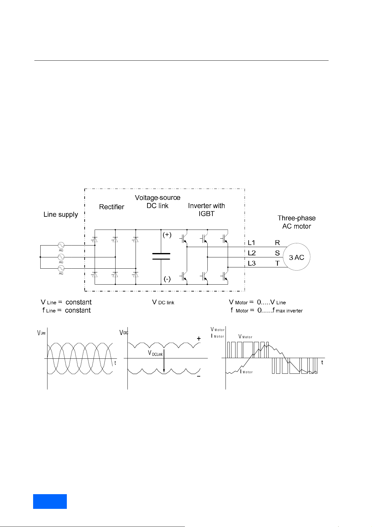
The converters in the SINAMICS product range are PWM converters with a voltage-source DC link. At the input side,
the converter consists of a rectifier (shown in the schematic sketch as a thyristor rectifier) which is supplied with a
constant voltage V
voltage V
DCLink
side converts the DC link voltage to a thr ee-phase s ystem with a variable voltage V
This process operates according to the principle of pulse width modulation PWM. By varying the voltage and the
frequency, it is possible to vary the speed of the connected three-phase motor continuously and virtually without
losses.
and a constant frequency f
Line
from a three-phase supply. The rectifier produces a const ant DC
Line
, i.e. the DC link voltage, which is smoothed by the DC link capacitors. The IGBT inverter on the output
and variable frequency f
Motor
Motor
.
Block diagram of a PWM converter with voltage-source DC link
Pulse modulation method
The power semiconductors of the IGBT inverter (IGBT = Insulated Gate Bipolar Transist or) are hig h-speed, el ectronic
switches which connect the converter outputs to the positive or negative pole of the DC link voltage. The duration of
the gating signals in the individual inverter phases and the magnitude of the DC link voltage thus clearly determi ne
the output voltage and therefore also the voltage at the connected motor.
SINAMICS Engineering Manual – May 2008
12/396
Siemens AG
Fundamental Principles and System Description
Engineering Information
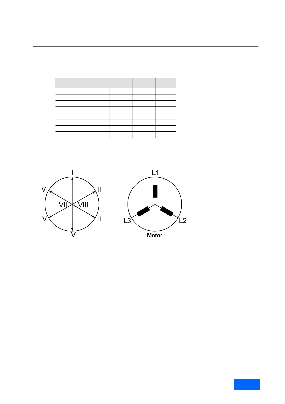
If we consider all three phases, there are a total of 2
states in the motor can be defined by voltage phasors.
Switching states of the
inverter
V
+ - -
1
V
+ + -
2
V
- + -
3
V
- + +
4
V
- - +
5
V
+ - +
6
V
+ + +
7
V
- - -
8
Phase
L1
If, for example, phase L1 is connected to the positive DC link voltage, and phases L2 and L3 to the negative voltage
so as to produce switching state V
, the resultant voltage phasor points in the direction of motor phase L1 and is
1
designated phase I. The length of this phasor is determined by the DC link voltage.
³ = 8 switching states in the inverter, and the effect of these
Phase
L2
Phase
L3
Representation of resultant motor voltages as phasor
If the switching state changes from V
to V2, then the voltage phasor rotates clockwise by an angle of 60°el due to the
1
change in potential at terminal L2. The length of the phasor remains unchanged.
In the same way, the relevant voltage phasors are produced by switching combinations V
combinations V
and V
7
produce the same potential at all motor terminals. These two combinations therefore pr od uc e
8
to V6. Switching
3
voltage phasors of "zero" length (zero voltage phasor).
Generation of a variable voltage by pulse width modulation
Voltage and frequency must be specified in a suitable way for a certain operatin g state of the motor, cha racterized by
speed and torque. Ideally, this corresponds to control of the voltage vector V
rotation t = 2
f and adjusted absolute value. This is achieved th rough modulation of the actual settable voltage
* *
space vectors (pulse width modulation). In this way, t he momentary value V
actual settable voltage space vectors and the voltage zero.
The solid angle is set directly by varying the ratio of the ON dur ations (pulse width) of adjacent voltage vectors, the
desired absolute value by varying the ON duration of the zero voltage vector. This method of generating gating
signals is called space vector modulation SVM. Space vector modulation provides sine-modulated pulse patterns.
on a circular path with the speed of
(t)
is formed by pulses of the adjacent,
(t)
SINAMICS Engineering Manual - May 2008
Siemens AG
13/396
Fundamental Principles and System Description
Engineering Information
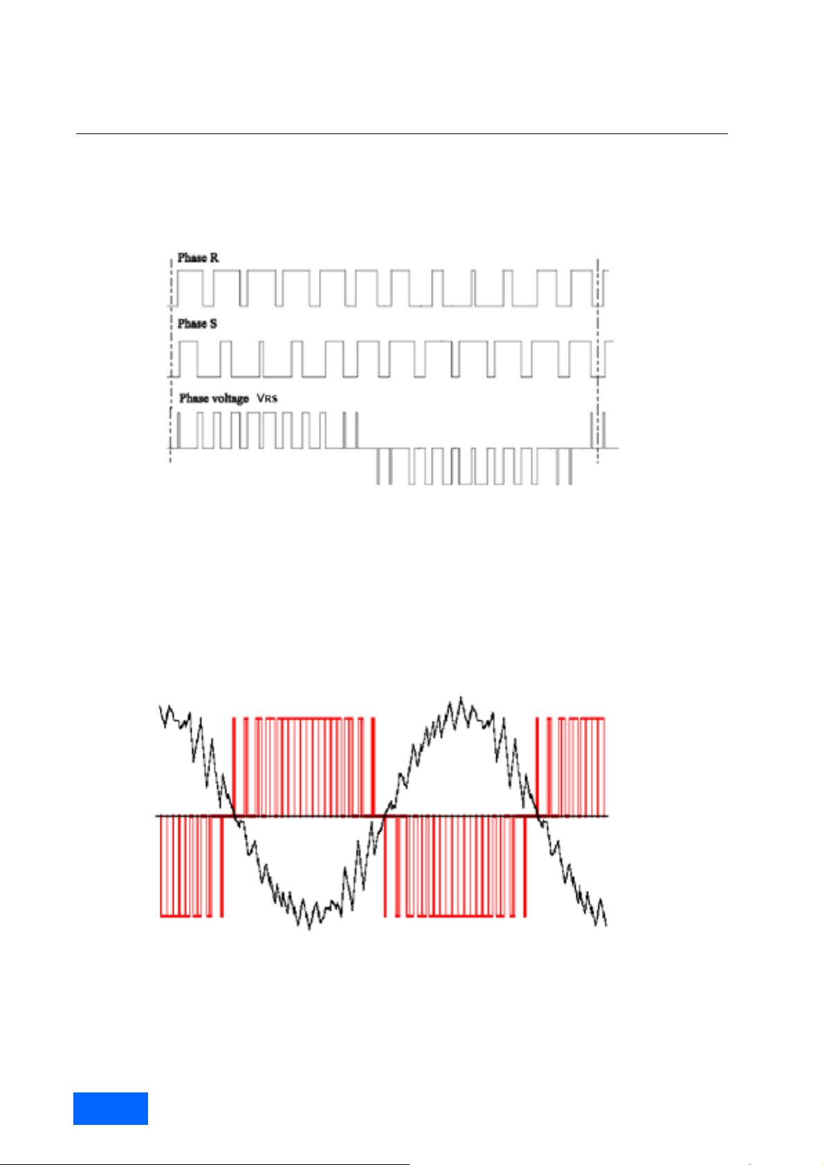
The following diagram illustrates how the voltages in p hases L1 (R) and L2 (S) plus output voltage V
(phase-to-
RS
phase voltage) are produced by the method of pulse width modulation and shows their basic time characteristics. The
frequency with which the IGBTs in the inverter phases are switched on and off is referred to as the pulse frequency or
clock frequency of the inverter.
Timing of the gating signal sequence for the IGBTs of the two inverter phases L1 (R) and L2 (S) plus the associated output
voltage V
(V- phase-to-phase). The amplitude of the voltage pulses corresponds to the DC link voltage.
RS
The diagram below shows the time characteristic (in red) of the invert er output voltage (phase-to-phase voltage) and
the resulting current (in black) generated in the motor when a stan dar d as ynchro nous mot or with a rated freque nc y of
50 Hz or 60 Hz is used and the inverter is operating with a pulse frequency of 1.25 kHz. The diagram shows that the
smoothing effect of the motor inductances causes the motor current to be v irtually sinuso idal, des pite t he fact that th e
motor is supplied with a square-wave pulse pattern.
Motor voltage (phase-to-phase) and motor current with space vector modulation
SINAMICS Engineering Manual – May 2008
14/396
Siemens AG

Fundamental Principles and System Description
Engineering Information
Maximum attainable output voltage with space vector modulation SVM
Space vector modulation SVM generates pulse patterns which approximat e an ideal si nusoid al motor voltage thro ug h
voltage pulses with constant amplitude and corresponding pulse-duty factor. The peak value of the maximum
(fundamental) voltage that can be attained in this way corresponds to the amplitude of the DC link voltage V
Thus the theoretical maximum motor voltage with space vector modulation which results is:
SVM
max
The true amplitude of the DC link voltage V
1
DCLink
VV
2
is determined by the method of line voltage rectification. In the case
DCLink
of rectifiers of the type used with SINAMICS G130 and G150 and also with S120 Basic Line Modules, it averages
1,41
*V
with no load, 1.35*V
Line
amplitude of V
DCLink
≈ 1.32*V
with partial load and 1.32*V
Line
at full load, the motor voltage theoretically attainable with space vector modulatio n
Line
.with full load. Thus with the true DC link voltage
Line
is:
V
SVM max
= 0.935 * V
Line
As a result of voltage drops in the converter and minimum pulse times and interlock times in the gating unit
responsible for generating the IGBT gating pulse pattern, the values in practice are lower. In practice, the values are:
V
SVM max
≈ 0.92 * V
(with pulse frequency of 2.0 kHz or 1.25 kHz according to the factory setting)
Line
For SINAMICS G130 chassis and G150 cabinets that were supplied with firmware versions < V2.3 until the autumn of
2005, this value is the maximum attainable output voltage as devices with this firmware are not capable of utilizing
pulse-edge modulation.
DCLink
.
Maximum attainable output voltage with pulse-edge modulation PEM
It is possible to increase the inverter output voltage abov e the values attained with space vector modulation by not
pulsing over the entire fundamental-wave period, but only at its edges. This process is referred to as pulse- edge
modulation (PEM). The basic waveform of the motor voltage is then as shown below.
Motor voltage with pulse-edge modulation PEM
The maximum possible output voltage is attained when clocking is perform ed with the fundamental frequency only,
i.e. when "pulsing" ceases altogether. The output voltage t hen consists of 120° rectang ular blocks with the amplitude
of the DC link voltage. The fundamental frequency RMS value of the output voltage can then be calculated as:
rect
66
So it is possible with pure rectangular modulation to achieve a motor voltage which is slightly higher than the line
voltage. However, the motor voltage then has an unsuitable harmonic spectrum which causes major stray losses in
the motor and utilizes the motor inefficiently. It is for this reason that pure square-wave modu lation is not utilized on
SINAMICS converters.
The pulse-edge modulation method used on SINAMICS converters perm its a maximum output voltage which is only
slightly lower than the line voltage, even when allowance is made for voltage drops in the converter:
V
PEM max
= 0.97 * V
Line
The pulse-edge modulation process uses o ptimized pulse patterns which cause only minor harmonic currents and
therefore utilize the connected motor efficiently. Commercially available standard motors for 50 Hz or 60 Hz and
utilized according to temperature class B in mains operatio n can be partia lly utilized acc ording to temp erature cl ass F
at the nominal working point up to rated torque when operated with pulse-edge modulation.
LineLineDCLink
VVVV 03.132.1
SINAMICS Engineering Manual - May 2008
Siemens AG
15/396

Fundamental Principles and System Description
Engineering Information
With introduction of firmware version V2.3 and simultaneous modification of the CIB board hardware (interface
module between the Control Unit and power unit), pulse-e dge modulation has been available as a stand ard feature
on the following SINAMICS units in vector control mode since autumn 2005:
SINAMICS G130* Chassis
SINAMICS G150* Cabinets
SINAMICS S150* Cabinets
SINAMICS S120* Motor Modules / chassis format
SINAMICS S120* Motor Modules / Cabinet Modules format
At low output frequencies and low depth of modulation, i.e. at low output voltage, these products utilize the sp ace
vector modulation SVM option and switch automatically over to pulse-edge modulation PEM if the depth of
modulation required at higher output frequencies is so high that it can no longer be provided by space vector
modulation (output voltage > 92 % of input voltage).
In principle it would be possible to reach an output voltage of over 92 % through overmodulation of the space vector
modulation (SVM). However, through doing this, the harmonics spectrum in the motor current would increase
considerably, which would lead to higher torque ripples and noticeabley higher motor losses. T herefore, SINAMICS
units operating in the vector control mode use pulse-edge modulation with optimised pulse patterns in order to
achieve optimum drive behaviour with regard to torque ripples and motor losses.
* Exceptions:
Parallel converters on which two or more power units operating in parallel are supplying one motor with a
common winding system. Under these conditions pulse-edge modulation cannot be selected.
If either a Basic or Smart Infeed is used to supply the inverter, the following formulas apply for the DC link
voltage at full load: V
edge modulation is limited to 92 % of the line input voltage.
If an Active Infeed is used to supply the inverter, the following formula applies to the DC link voltage bec ause the
Active Infeed utilizes a step-up converter function: V
This means that the maximum output voltage even without pulse-edge modulation ca n correspond to 100 % of
the line input voltage or higher if the parameters of ratio V
Active Infeed. This is described in the section “SINAMICS Infeeds and their properties”, subsection “Active
Infeed”.
Converters with output-side sine-wave filter. Pulse-edge modulation cannot be selected under these conditions.
If either a Basic or Smart Infeed is used to supply the inverter, the following formulas apply for the DC link
voltage at full load: V
limited to 85 % of the line input voltage for units with a supply v oltage of 380 V to 48 0 V 3AC and to 83 % for
units with a supply voltage of 500 V to 600 V 3AC.
If an Active Infeed is used to supply the inverter, the following formula applies to the DC link voltage bec ause the
Active Infeed utilizes a step-up converter function: V
This means that the maximum output voltage even without pulse-edge modulation ca n correspond to 100 % of
the line input voltage or higher if the parameters of ratio V
Active Infeed. This is described in the section “SINAMICS Infeeds and their properties”, subsection “Active
Infeeds”.
:
Note
Pulse-edge modulation PEM is only available in vector control mode. In servo control mode, the converters
always operate with space vector modulation (SVM). The reason for this is the slig ht lo wer dynamic performance
of the drive when it is operating with pulse- edge modulation. This can be accepted in almost all vector co ntrol
applications, but not in high-dynamic servo control applications.
With the introduction of Firmware version V2.5 SP1 and the simultaneous chan ging of the hard ware, pulse-edge
modulation is available as standard also for Booksize units since autumn 2007.
DCLink
DCLink
≈ 1.32 • V
≈ 1.32 • V
resp. 1.30 • V
Line
resp. V
Line
Line
DCLink
= 1.30 • V
DCLink
DCLink
. Therefore the maximum output voltage without pulse-
> 1.42 • V
/ V
DCLink
. In this case, the maximum output voltage is
Line
> 1.42 • V
/ V
DCLink
(factory setting: V
Line
are set to sufficiently high values on the
Line
(factory setting: V
Line
are set to sufficiently high values on the
Line
DCLink
DCLink
= 1.5 • V
= 1.5 • V
Line
Line
).
).
SINAMICS Engineering Manual – May 2008
16/396
Siemens AG

Fundamental Principles and System Description
Engineering Information
The pulse frequency and its influence on key system properties
The pulse frequency of the inverter is an important param eter which has a crucial influence on various properties of
the drive system. It can be varied within certain given limits. In order to reduce the motor noise, reac h very high
output frequencies or in the event that sinus filters are to be used at the converter output, it is sensible, or rather
necessary, to increase the pulse frequency.
The following aspects of the pulse frequency are described briefly below:
The pulse frequency factory settings
The limits within which the pulse frequency can be adjusted
The effect of the pulse frequency on various properties of the drive system
When it is advisable or even essential to change the pulse frequency
What needs to be noted in connection with motor-side options (motor reactor, motor filter).
Factory settings and pulse frequency setting ranges
The pulse frequency of the motor-side inverter on SINAMICS G130, G150, S150, S120 (Chassis and Cabinet
Modules) operating in vector control mode is preset at the factory to 2.0 kHz or 1.25 kHz as specified in the table
below.
Line supply voltage Power Rated output current Pulse frequency factory
380 V to 480 V 3AC ≤ 250 kW ≤ 490 A 2.00 kHz
≥ 315 kW ≥ 605 A 1.25 kHz
500 V to 600 V 3AC All power ratings All currents 1.25 kHz
660 V to 690 V 3AC All power ratings All currents 1.25 kHz
Converter-dependent factory setting of pulse frequency for SINAMICS G130, G150, S150
and for SINAMICS S120 Motor Modules, Chassis and Cabinet Modules
The pulse frequency can be varied in discret e steps. Possi b le settings corr espo nd to twice the factory setting value in
each case as well as whole multiples thereof. Depending on the unit type, the pulse frequency can therefore be
increased to 8 kHz (when factory setting is 2 kHz) or to 7.5 kHz (when factory setting is 1.25 kHz). Switching between
integer multiples of the pulse frequency is also possible when the drive is in operati on.
With introduction of firmware version V2.4 in the summer of 2006 intermediate values can als o be parameterized,
allowing the pulse frequency to be set in relatively fine increments. This setting of intermediate values is only p ossibl e
when the drive is not in operation.
Influence of the pulse frequency on the inverter output current
The pulse frequency factory setting of eith er 2.0 kHz or 1.25 kHz is relatively low to generate low inverter s witching
losses. If the pulse frequency would be increased, and this can be done at any time by adjustment of the param eter
settings, the switching losses in the inverter and thus the overall losses in the conv erter would increase accordingl y.
The result would be overheating of the power unit if the inverter would operate at full capacity. For this reason, the
conducting losses must be lowered in order to compensate for the increase of the switching losses. T his can be
achieved by reducing the permissible output current (current derating). The pulse-frequency-dependent current
derating is specific to individual units. This has to be taken into account when dimensio ning a c onverter. T he derating
factors for integer multiples of factory settings can be found in the chapters on specific unit types. The derating
factors for intermediate values can be ascertained through linear interpolation between the corresponding table
values.
Influence of the pulse frequency on losses and efficiency of inverter and motor
With the factory set pulse frequency of 2.0 kHz or 1.25 kHz, the motor current is already close to sinusoidal. The
stray losses in the motor caused by harmonic currents are low, but not negligible. Commercially availabl e standard
motors for 50 Hz or 60 Hz and utilized according to temperature class B in mains operation can be partially utilized
according to temperature class F at the nominal working point up to rated torque when operated on a converter. The
winding temperature rise is then between 80 and 100 K.
Raising the pulse frequency on standard mot ors for 50 Hz or 60 Hz reduces the motor stray losses only slightly, but
results in a considerable increase in the converter switching loss es. The efficiency of the overall system (converter
and motor) deteriorates as a result.
setting
SINAMICS Engineering Manual - May 2008
Siemens AG
17/396

Fundamental Principles and System Description
Engineering Information
Influence of the pulse frequency on motor noise
A higher level of magnetic motor noise is excited when three-phase moto rs are operated on PW M converters. This is
caused by the voltage pulsing which results in additional voltage and current harmonics.
According to DIN VDE 0530 or IEC 60034-17 "Rotating electrical machines / Squirrel-cage induction motors fed from
converters - Application guide“, the A-graded noise pressure level i ncreases in the order of magnitude of between
5 dB and 15 dB when three-phas e motors are operated on a PWM converter up to rated frequency as compared to
motors of the same type operating on sinusoidal volta ge at rated frequency. The actual values depend on the PWM
method used, the pulse frequency of the converter and the design and number of poles of the converter-fed motor.
In the case of SINAMICS converters operating at the factory-set pulse frequenc y, the additional noise pr essure level
produced by the motor as a result of the converter supply is in the order of magnitude of between 5 dB(A) and
maximum 10 dB(A).
A reduction of the additional motor noise caused b y the conv erter su pply ca n gener all y b e achi eved by an incre ase in
the pulse frequency. It can therefore be meaningful to raise the pulse frequenc y in ord er to attenuate the motor nois e.
It must be noted that the inverter current may need to be reduced (derated) with an increased pulse frequency and
other limitations may apply with respect to motor-side options such as motor reactors, dv/dt filters plus VPL (Voltage
Peak Limiter) and sine-wave filters.
Correlation between pulse frequency and converter output frequency (fundamental wave frequency)
With space vector modulation, there is a fixed correlatio n between the pulse frequency and the m aximum attainable
converter output frequency (fundamental wave frequency) . The pulse frequency must be at least 12.5 times higher
than the required converter output frequency on SINAMICS converters. This means that the maximum achievabl e
output frequency at a given pulse frequency is limited according to the formula
= f
f
Converter max
The table below shows the possible pulse frequency settings and the associated maximum achievable output
frequencies for converters and inverters with the factory set pulse freq uencies f
pulse frequency setting scale is expanded with firmware version V2.4 and higher.
Units with factory setting f
Pulse frequency Max. output frequency Pulse frequency Max. output frequency
2.0 kHz 160 Hz 1.25 kHz 100 Hz
4.0 kHz 300 Hz 2.50 kHz 200 Hz
8.0 kHz 300 Hz 5.00 kHz 300 Hz
- - 7.50 kHz 300 Hz
Settable pulse frequencies and associated maximum attainable output frequencies on SINAMICS converters
Correlation between pulse frequency and motor-side options (motor reactor and motor filter)
If motor reactors, dv/dt filters p
pulse frequency and thus also the maximum output frequency are limited by these options. In some cases, a fixed
pulse frequency is specified:
Permissible pulse frequency with motor reactor (SINAMICS):
The maximum pulse frequency is limited to twice the value of the factory setting, i.e. to 4 kHz on units with
factory setting 2 kHz and to 2.5 kHz on units with factory setting 1.25 kHz. The maximum output frequency is
limited to 150 Hz independent of the selected pulse frequency.
Permissible pulse frequency with dv/dt filter plus VPL (SINAMICS)
The maximum pulse frequency is limited to twice the value of the factory setting, i.e. to 4 kHz on units with
factory setting 2 kHz and to 2.5 kHz on units with factory setting 1.25 kHz. The maximum output frequency is
limited to 150 Hz independent of the selected pulse frequency.
Permissible pulse frequency with sine-wave filter (SINAMICS):
Sine-wave filters are available for voltage levels 38 0 V to 480 V 3AC and 500 V to 600 V 3AC. The pulse
frequency is a mandatory fixed value and equals 4 kHz (380 V to 480 V) or 2.5 kHz (50 0 V to 600 V). The
maximum output frequency is limited to 150 Hz.
Permissible pulse frequency with sine-wave filter (external supplier):
The pulse frequency and maximum output frequency must be set according to the filter manufacturer's
instructions.
/ 12.5 (but a maximum of 300 Hz on asynchronous machines with vector control mode).
pulse
= 2.0 kHz or f
= 2.0 kHz Units with factory setting f
pulse
pulse
= 1.25 kHz
pulse
pulse
lus VPL or sine-wave filters are installed at the motor output, the maximum permissibl e
= 1.25 kHz. The
SINAMICS Engineering Manual – May 2008
18/396
Siemens AG

Fundamental Principles and System Description
Engineering Information
Output power ratings of SINAMICS converters and inverters / Definition of the output power
SINAMICS converters produce an electrical three-phase system at their output, the power of which – taking into
consideration factor √3 – can be calculated from the output voltage and th e output current, whereby any phase angle
can exist between output voltage and output current, depending on the load characteristics. Therefore electrical
output power, for which the converter’s output is designed, presents an apparent power
phase angle. This apparent power can be calculated from the obtainable output voltage and the permanent
permissible thermal output current, which is the rated output current I
When it is taken into consideration that
rated.
SINAMICS converters in the vector control mode reach at the output almost the value of the incoming suppl y voltage
by using pulse-edge modulation, the apparent output power of the converter can be ca lculated using the following
formula:
S
rated
= √3 • V
line
• I
rated
.
This apparent output power of the converter is a physically correct value, but it is not really suitab le to allow a simpl e
correlation between the converter output power and the rated motor power as the appa rent power of the converter
(given in kVA) and the mechanical shaft power (rated power) of the motor (given in kW) do not directly correspond
because current, power factor and efficiency of the motor are required.
A much simpler option for the coordination of the output power of the converter and the rated power of the motor is
the definition of an active output power for the converter, which is deduced from the mecha nical shaft power (rated
power) of a typical three-phase asynchronous motor which can be operated by the converter.
Definition of the output power for SINAMICS converters and inverters
The active output power of a SINAMICS converter or inverter is defined as the m echanical shaft po wer (rated po wer)
of a typical, 6-pole, asynchronous motor, which can be op erated by the converter or inv erter at its rated point, without
overloading the converter or inverter. As 2 and 4-pole motors al ways have a better power factor and also equal or
lower rated currents, all 2, 4 and 6-pole motors are covered by the definition of the o utput power given above with
regard to the coordination of the power between converter and motor.
In the SINAMICS catalogs and operating instructions (equipment manuals), usually several values for the output
power of the converters or inverters are given:
Output power on the basis of the base load current I
Output power on the basis of the base load current I
for low overloads
L
for
high overloads
H
Each value for the output power of converters and inverters applies to motors with rated voltages of 400 V, 500 V or
690 V as well as a rated frequency of 50 Hz. (The definition of the standard load duty cycles – low overload and high
overload – and the definition of the corresponding base load currents I
and IH is given in the section “Load duty
L
cycles”). It is particularly important with SINAMICS S120 and S150 units with the wide input voltage range of 5 00 V 690 V 3AC that the values for the output power of these units are depending on the voltage. Therefore they are
significantly different for 500 V and 690 V.
The following example should clearly illustrate how the output power for a SINAMICS converter is determined:
Converter data:
Line supply voltage 380 V – 480 V
Rated output current 605 A
Base load current I
Base load current I
for low overload 590 A
L
for high overload 460 A
H
Rated power and rated current for cataloged asynchronous
motors in the 1LA8 range, for operation at 400 V / 50 Hz:
Number of
poles
p
2 - - 520 A 590 A 660 A
4 - 430 A 540 A 610 A 690 A
6 345 A 430 A 540 A - 690 A
200 kW 250 kW 315 kW 355 kW 400kW
as a result of the existing
SINAMICS Engineering Manual - May 2008
Siemens AG
19/396

Fundamental Principles and System Description
Engineering Information
The output power of the above-mentioned converter for lo w overload, on the basis of the base load current I
at
L
400 V 3AC/50 Hz, is defined as the the rated power of the largest, 6-pole asynchronous motor for 400V/50 Hz
operation, the rated current of which does not exceed the base load current I
this definition the converter has the output power of 315 kW at 400 V on the basis of I
= 590 A of the converter. According to
L
.
L
The output power of the converter, which, as the rated power of the motor, is give n in kW, offers the possibility of a
very simple and safe coordination between the power of the converter and the m otor, without having to take into
consideration other details such as current, power factor and efficiency. If the output power of the converter is chose n
at least as big as the rated power of the motor, it is always safe to oper ate 2, 4 and 6-pole motors at full load with the
selected converter.
It can, however, be noted that, in some cases, motors with a low number of po les (2 or 4), whose rated power is
larger than the output power of the converter, can be operated at their rated point without overloading the converter.
In the above-mentioned example this is the case for the 2-pole motor with a rated current of 590 A and a rated po wer
of 355 kW.
Therefore on the one hand, the output power of the converter offers and extremely simple and safe way of
coordinating the power of a converter and a motor. On the other hand, however, this coordination can lead to an
overdimensioning of the converter in combination with motors with a low number of poles. If you want to achieve
optimum coordination between the converter and the motor, you must choose the more complicated method involving
the currents.
SINAMICS Engineering Manual – May 2008
20/396
Siemens AG
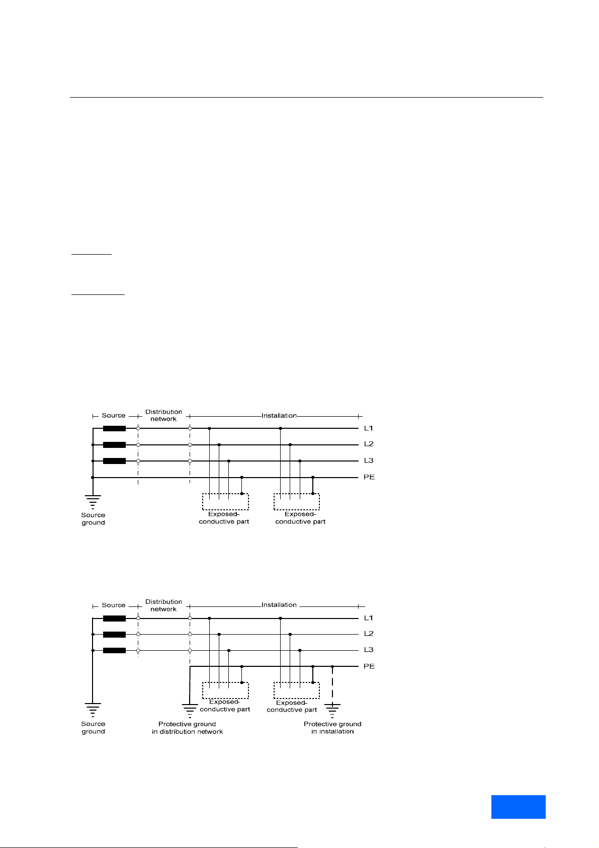
Fundamental Principles and System Description
Engineering Information
█ Supply systems and supply system types
General
The low-voltage products in the SINAMICS series with line supply voltages of ≤ 690 V are normally connected to
industrial supply systems that are supplied from the medium-voltage distribution system via transformers. In rare
cases, however, these devices may be directly connecte d to the public low-voltage supply systems or to separate
supply systems, such as those supplied by diesel-electric generators.
According to IEC 603 64-3 supply systems are classified as either TN, TT or IT systems depending on the t ype of
arrangement of the live parts, the exposed-conductive parts and the grounding method. The classifications and
letters are explained in brief below.
First letter: Relationship of the supply system to ground:
T = Direct connection of one point to ground.
I = All live parts isolated from ground, or one point connect ed to ground through an impedance.
Second letter
T = Direct electrical connection of the exposed-conductive parts (enclosures) to ground, independent of
N = Direct electrical connection of the exposed-conductive parts (enclosures) to the grounded point of the
In TN systems, one point is directly grounded and the exposed-conductive parts (enclosures) of the electrical
installation are connected to the same point via a protective conductor (protective earth PE).
: Relationship of the exposed-conductive parts (enclosures) of the installation to ground:
whether one point of the supply system is already grounded.
supply system (the grounded point of the supply system is generally the star point in three-ph ase
systems, or one of the three phases if the system has no star point).
Example of a TN supply system
In TT systems, one point is directly grounded and the exposed-conductive parts (enclosures) of the installati on are
connected to ground electrodes which are electrically independent of the ground electrodes of the supply system.
Example of a TT supply system
SINAMICS Engineering Manual - May 2008
Siemens AG
21/396
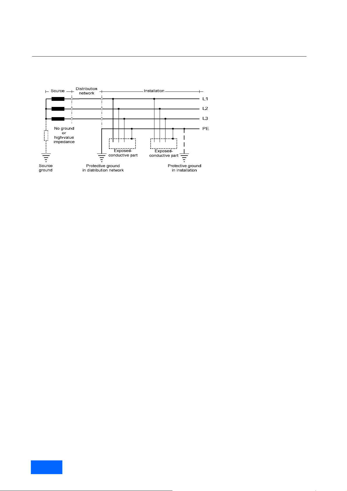
Fundamental Principles and System Description
Engineering Information
In IT systems, all live parts are isolated from ground, or one point is connected to ground through a high-value
impedance. All the exposed-conductive parts (enclosures) in the electrical installation are connected to an
independent ground electrode, either separately or in a group.
Example of an IT supply system
Connection of converters to grounded systems (TN or TT)
SINAMICS converters are designed for connection to grounded TN or TT systems, i.e. three-phase s upply systems
with a grounded star point. The devices are equipped with means of connecting the three phase conductors L1, L2,
L3 and the protective conductor (PE) to ground. No connection for a s eparate neutral conductor (N) is provided, nor
is one necessary as the converters place a symmetrical load on the three-phase system and the star point is not
therefore loaded.
If a single-phase AC voltage, e.g. 230 V, is required to suppl y auxiliaries or the fan, this is supplied internally via
single-phase control-power transformers that are connecte d between two phase conductors. Alternatively, it can b e
supplied from an external source.
It is not essential to install an earth-leakage monitor at the converter input. However, suitable precautions must b e
taken to ensure that the substantial ground-fault current caused b y groun d faults in the device is prom ptly interr upted .
On SINAMICS G150 and S150 cabinets and S120 Cabinet Modules, this protection can be provided by optional line
fuses or, at higher current ratings, by optional circuit breakers in the converters themselves. The type 3NE1 fuses
recommended for this purpose are dual-function fuses whic h provide both line protection as well as semiconductor
protection for the thyristors and diodes in the rectifiers of G150 and S120 Basic Infeeds. In systems using S120
Smart Infeeds and S120 Active Infeeds and in S150 cabinets containing IGBT rectifiers, semiconductor protection
cannot be provided by fuses of any type due to the e xtremely low I
however, considerably restrict the extent of damage if a rectifier has a serious fault.
Ground faults in the motor cable at the output side or in the motor itself can b e detected by the electr o nic groun d fa ult
monitor implemented in the inverter. The response threshold of this monitor can be parameterized to valu es higher
than about 10 % of the rated output current.
SINAMICS units for operation in grounded TN and TT systems are equipped as standard with RFI suppression filter s
for the "second environment” (category C3 according to the EMC product standard EN 61800-3). This applies to
SINAMICS G150 and S150 cabinets, to SINAMICS G130 Chassis and to the Infeeds (Basic Infeeds, Smart Infeeds
and Active Infeeds) of the S120 modular system (Chassis and Cabinet Modules). For more inform ation about RFI
suppression, please refer to the section "Line filters" or to the chapter "EMC Installation Guideline".
2
t values of the IGBT chips. Type 3NE1 fuses,
Connection of converters to non-grounded systems (IT)
SINAMICS converters can also be connected to and operated on non-grounded IT suppl y s ystems. The advantage of
IT systems as compared to grounded supply s ystems is that no ground-fault current can flow when a ground fault
occurs and operation can therefore be maintained. The system does not shut down on faults unti l a second ground
fault occurs. This advantage means that IT supply systems are widely used in areas where fault tripping ne eds to be
reduced to a minimum due to the processes being carried out (e.g. in the chemical, steel, and paper industry).
SINAMICS Engineering Manual – May 2008
22/396
Siemens AG
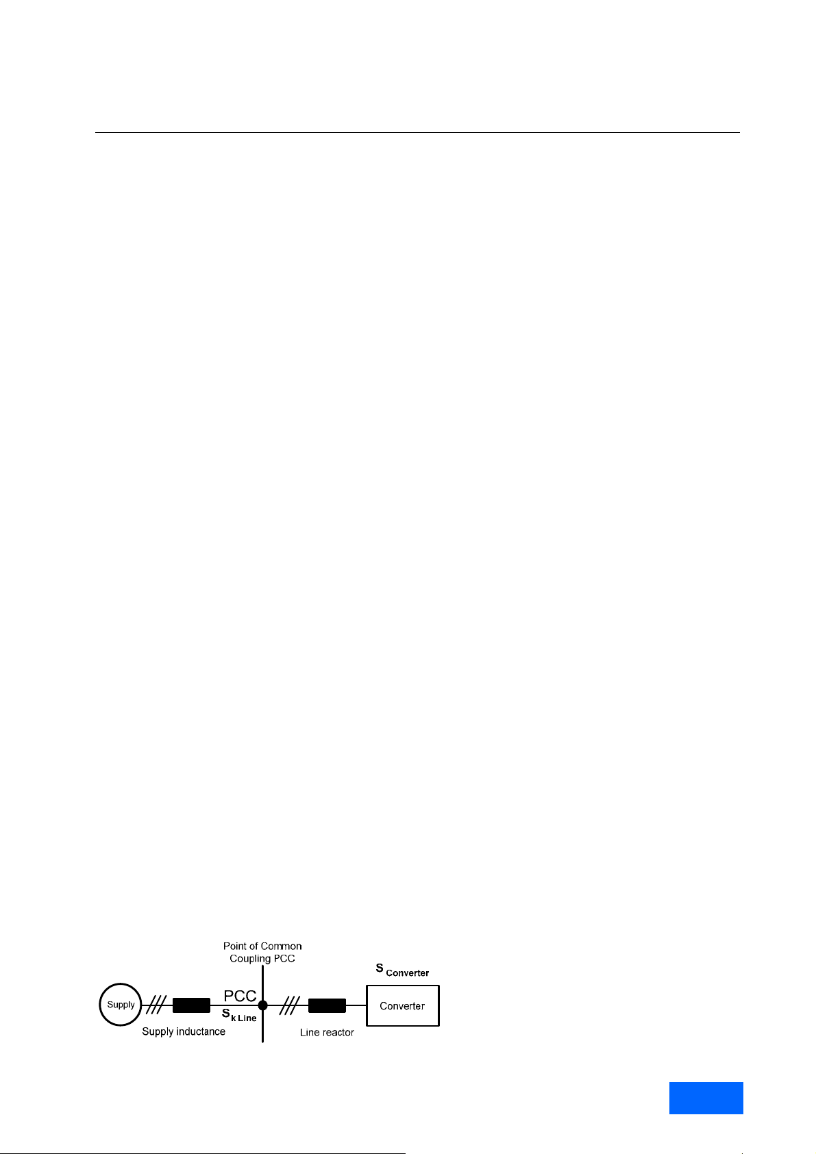
Fundamental Principles and System Description
Engineering Information
An initial ground fault, however, must be detected and eliminated promptly for two reasons. First, a second ground
fault occurring will lead to a short circuit current and therefore to a fault tripping and, in turn, to an i nterruption in
operation. Second, a phase conductor or pol e of the DC li nk in th e co nvert er is grou nded when a groun d fault occ urs,
which leads to a 1.73 to 2.0 times higher operational voltage load on the converter and motor insulation at the
conductors that are not affected. In the short term, this increased voltage load do es not have a critical effect on the
converter and motor but, over extended periods of operation (more than 24 h ours), it can reduce the lifetime of the
motor winding. As a result, ground fault detection by means of an insulation monitor is crucial.
Ground faults can be detected at a central location in the IT supply system or in the SINAMICS converter itself.
Insulation monitors such as those supplied by Bender have proven to be suitab le and successful. Insulation monitors
are available as option L87 for G150 and S150 cabinets and for S120 Line Connection Modules.
A common drive configuration that is operated as a non–grounded IT supply system is a 12-puls e drive, which is
supplied by a three-winding transformer. This transform er has one secondary winding with a star connection and
another with a delta connection. Since the delta-connected winding does not have a star point that can be properly
grounded, 12-pulse drives are operat ed with two non-grou nded secondary windings i.e. as an IT supply s ystem. For
this reason, 12-pulse-operated converters such as 12-pulse-operated SINAMICS G150 paralle l converters must be
equipped with option L87/insulation monitor.
When installing or commissioning SINAMICS devices in an IT supply system, the grounding connection for the RFI
suppression filters found as standard in SINAMICS device s and designed for the “second environmen t” (category C3
in accordance with the EMC product standard EN 61800-3) must be ope ned. This can be done s imply by remov ing a
metal clip on the filter as described in the operating instructions. If this is not do ne, the capacitors of the suppressio n
filters will be overloaded and possibly destroyed b y a ground fault at the motor side. When the ground ing connection
for the standard RFI suppression filter has been removed, the devices me et categor y C4 in accordance with the EMC
product standard EN 61800-3. For more information, refer to the chapter “EMC Installation Guideline”.
The lack of ground connection in IT supply systems means t hat the line voltage c an theoretically dr ift by any amount
from ground potential, so that surge voltages to ground of inf inite m agn itude would be p oss ible. T his is fort unate l y not
the case in practice as the line voltage is coupled capacitively to ground by the capacitance of the transformer
winding and line feeder cables. This capacitive ground connection ensures that the neutral of the non-grounded
system is practically at ground potential in normal, symmetrical three-phase operation and that voltages to ground are
very similar to those in TN systems.
In the event of a ground fault (in particular, when a ground fault occurs at the c onverter DC link or motor), however,
an operational voltage with respect to ground that is 1.73 to 2.0 times higher than in the T N system develops in the IT
system. Under these conditions, therefore, the drive system will no longer have any large reserves with respect to
insulation. For this reason, transient overvoltages injected into the system from an external source (e.g. due to
switching operations in the medium-voltage power suppl y or by lightning strikes) are deemed to be more critical i n
this situation than during normal operation. Even in large-scale systems equipped with several converters in the
medium to high output power range, a risk of transient overvoltages with respect to ground e xists, which can damage
the devices.
For this reason, we strongly recommend the installation of surge arreste rs to ground in IT supply systems. A surge
arrester must be connected between each phase and ground and located, where possible, directly at the Infeed
transformer. Suitable surge arresters are available from suppliers such as Dehn.
Connection of converters to supply systems with different short-circuit powers
Definition of relative short-circuit power RSC
The relative short-circuit power RSC (Relative Short-Circuit power) at the point of common coupling (Point of
Common Coupling) is defined as th e ratio between the shor t-circuit power S
S
Converter
of the connected converter(s).
SINAMICS Engineering Manual - May 2008
Siemens AG
at the PCC and the apparent power
K line
23/396

Fundamental Principles and System Description
Engineering Information
Supply systems with high relative short-circuit power RSC > 50 (strong systems)
Relative short-circuit powers of RSC > 50 always require the installation of line reactors for 6-pulse rectifier circ uits
(G130, G150, S120 Basic Line Modules and S120 Smart Line M odules). These limit the line-side curre nt harmonics
and protect the converter (rectifier and DC link capacitors) against thermal overloadin g. In the case of 6-puls e rectifier
circuits equipped with Line Harmonics Filters LHF and Active Infeeds (S150, S120 Active Line Modules), no specia l
conditions need to be observed.
Supply systems with medium relative short-circuit power 15 ≤ RSC ≤ 50
Supply systems with medium-level, relative short-circuit power in the 15 ≤ RSC ≤ 50 range do not generally
necessitate any special measures. Depending on the converter output rating, it might be necessary to install line
reactors where 6-pulse rectifier circuits are used. In the case of 6-pulse rectifier circuits equipped with Line
Harmonics Filters LHF and Active Infeeds (S150, S120 Active Line Modules), no special conditions need to be
observed.
Supply systems with low relative short-circuit power RSC < 15 (weak systems)
If SINAMICS converters are connected to supply systems with a low, relative short circuit power RSC < 15, it must be
noted that not only the supply system perturbation, i.e. the voltage harmonics in the line vo ltage, is increasing but
also other undesirable side-effects may occur.
If the RSC value drops to below 10 with a 6-pulse rectifier circuit, the voltage harmonics can reach critical levels. The
permissible harmonic limits specified in the standards are exceeded an d reliable operatio n of the converter and other
equipment connected at the PCC can no longer be gu arant eed. F or a dditiona l i nformatio n, pleas e refer to "Standar ds
and permissible harmonics" in the section "Harmonic effects on supply system".
If the RSC value drops to below 10 with a 6-pulse rectifier circuit i ncluding a Line Harmonics Filter, the detuning of
the Line Harmonics Filter caused by the high impedance o f the supply system will lead to a considerable incre ase of
the fundamental wave of the line voltage. This can reach values beyo nd the permissible line volt age tolerance of the
converter, which means that the system can no longer function properly.
Restrictions also apply in the case of Active Infeeds. With RSC values of < 15, the dynamic control response is
impaired and the voltage harmonics at pulse frequency in the line voltage start to rise significantly. With RSC values
of < 10, there is the same risk as with 6-pulse rectifier circuits that the converter and other equipment connected at
the PCC will no longer operate reliably.
Relative short-circuit power values of RSC < 10 can be encountered, for example, when converters are supplied b y
transformers of the correct rating that have high relative short-circuit voltages of u
generally also encountered when converters are operated on separate supply systems which are supplied by dieselelectric generators of the correct rating. In such cases, the power supply conditions must be analyzed precisely. It is
often necessary to consider overdimensioning the transformers or gener ators in order to reduce voltage harmonics.
When Infeeds with regenerative capability (Smart Infeeds or Active Infeeds) are supplied by diesel-electric
generators, the appropriate parameters should be set to prevent the system from operating in generator mode.
An extremely weak supply system would be, for example a very lo w-output laboratory or test bay supply on which a
high-powered, variable-speed drive needs to be tested.
If the drive were operated under no load, there could be no objectio n to this type of constellation. Very little active
power is required under no load condition and the supply system would not be overloaded in terms of power drawn.
If a converter comprises a 6-pulse rectifier without Line Harmonics Filter on the line side (SINAMICS G130, G150 and
S120 Basic Line Modules or S120 Smart Line Modules), the supply system perturbation is on an acceptable level due
to the low line current, which makes this configuration suitable for testing purp oses. Although 6- pulse drives with Lin e
Harmonics Filters have no problems regarding harmonics, there is still a risk as described above that the
fundamental wave of the line voltage will increase due to the detuni ng of the filter, which means that the system can
no longer function properly.
If powerful drives with Active Infeeds are to be tested (SINAMICS S150 or drives with S120 Active Line Modules), an
arrangement of this type is critical with respect to voltage harmonics. The harmonics at the line side which are
normally kept very low by the Clean Power Filter can cause such distortions in the line voltage, even under no load
conditions, due to the high impedance of the weak supply system that the closed-loop control of the Active Infeed can
start to malfunction. In such cases, the system cannot operate properly, even if the Active Infeed c losed-loop control
has been optimally parameterized.
> 10 %. RSC values of < 10 are
k
SINAMICS Engineering Manual – May 2008
24/396
Siemens AG
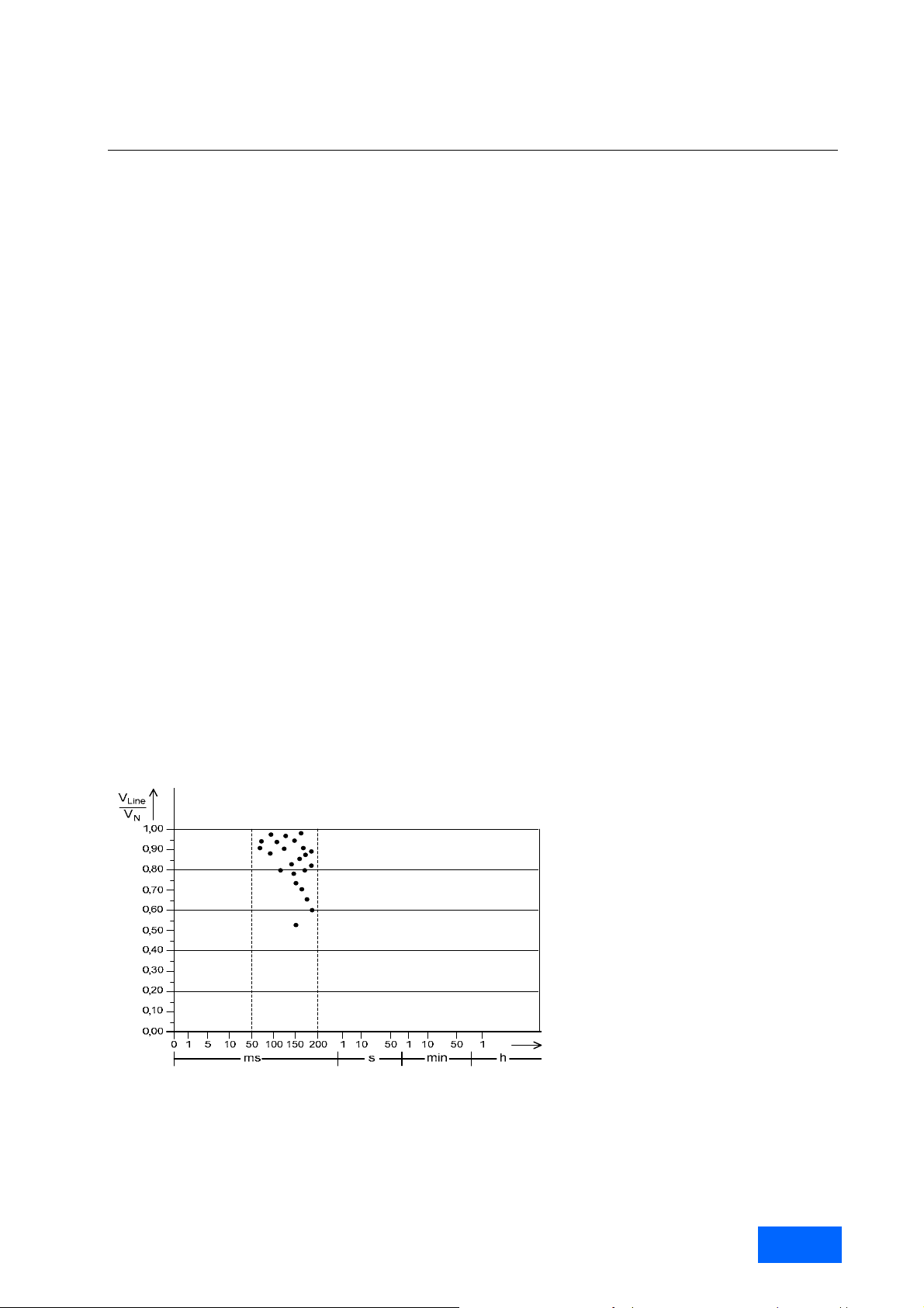
Fundamental Principles and System Description
Engineering Information
Supply voltage variations and supply voltage dips
General
The voltage of the power supply systems is usually not constant but rather susceptible to noticeabl e changes, as a
result of load variations, switching operations and individual occurrences, such as short circuits. The connected
SINAMICS units are inevitably affected by these changes and show different reactions to them, depending on the
magnitude and duration as well as on the operating conditions of the drive. These reactions range from entirely
unaffected operation over operation with certain restrictions to the complete drive shut-down.
The following paragraphs deal with the most important types of supply vo ltage chang es, their causes, magnitude a nd
duration. Afterwards the behaviour of SINAMICS units during supply voltage variations and su pply voltage dips will
be explained.
Supply voltage variations are relatively slow, long-term increases or decreases of the RMS value (root mean
square value) of the supply voltage, which usuall y occ ur as a res ult of lo ad vari atio ns in t he po wer suppl y system, the
switching of the transformer tap changers and other operational adjustments in the power supply system . According
to EN 61000-2-4, it is possible, in European interconnected supply systems, to assume th e following typical variations
in the nominal supply voltage VN:
0.9 • VN ≤ V
0.85 • V
Supply voltage dips are characterized by a sudden decrease in the supply voltage, followed by a restoration shortly
afterward. Supply voltage dips are usually associated with the emergence and disappearance of short-circuits or
other very large current increases in the supply (e.g. the starting of relati vely large motors directly at the supply wit h
correspondingly high starting currents). Supply voltage dips var y quite a lot with regard to their depth and duration.
The depth of a supply voltage dip depends o n the location of the s hort circuit and the current increase. If this occurs
close to the unit’s connection point, the dip will be large, if it occurs far away from the connection point, it will be
small. The duration of the dip depends, when short circ uits occur in the supply system, how quickly the protection
device, such as fuses or circuit breakers, respond and clear the short circuit. In European interconnected supply
systems, it is possible, according to EN 50160, to assume the following approximate values for supply voltage dips:
0.01 • V
N
≤ V
The following diagram shows supply voltage dips in a t ypical, European interconnected supply system over a time
period of two months. The supply voltage dips are in the range of 0.5 • V
50 ms and 200 ms, whereby very large dips occur very seldom.
≤ 1.1 • V
Line
≤ V
N
Line
≤ 0.9 • VN (short-term, i.e. < 1 min)
Line
≤ VN (very short-term, i.e. 10 ms to approx. 1 s)
(permanent)
N
N
≤ V
≤ VN with a duration of between
Line
Supply voltage dips in a typical European interconnected supply system
Outside Europe, larger and longer supply voltage dips can occur more frequently, particularly in states with fewer
closely connected power supply systems, such as those in the USA, Russia, China or Aust ralia. Here supply voltage
dips which last a second or longer must be expected.
SINAMICS Engineering Manual - May 2008
Siemens AG
25/396

Fundamental Principles and System Description
Engineering Information
Behaviour of SINAMICS converters during supply voltage variations and dips
Supply voltage ranges
SINAMICS units are dimensioned for relatively wide supply voltage ranges, whereby each range covers several of
the worldwide nominal supply voltages V
The converter chassis units SINAMICS G130 and the converter cabinet units SINAMICS G150 are available in three
supply voltage ranges. The components of the modular system SINAMICS S120 (Chassis and Cabinet Modules) as
well as converter cabinet units SINAMICS S150 are available in two supply voltage range s. The supply v oltage ran ge
of the units has to be selected so that the on-site nominal supply voltage V
range.
SINAMICS unit
SINAMICS G:
G130 / G150
SINAMICS S:
S120 (Chassis and Cabinet Modules) and S150
Supply voltage ranges for SINAMICS G130, G150, S120 (Chassis and Cabinet Modules) and S150
During commissioning, the units must be set up to the on-site available nominal supply voltage VN:
Hardware set-up: Adaptation of the line-side transformer t ap for the internal supply of
auxiliaries with 230 V and adaptation of the lin e-side transformer tap for
the supply of the fans with 230 V.
F irmware set-up: Adaptation of parameter P0210 / Supply voltage
These settings are absolutely essential, in order th at the units behave optimally dur ing supply voltage variati ons. On
the one hand, they ensure that the units are as insusceptible as possible to supply voltage variations and that
unnecessary fault trips are avoided. On the other han d, they also ensure that the units react to unacceptably large
supply voltage changes with prompt fault trips, thus avoiding any damage being incurred to the units.
The hardware settings also guarantee a sufficient level for the 230 V produced by the transformers for the a uxiliaries
and the fans at lower supply voltage and prevent the overloading of the 230 V auxiliaries when the suppl y voltage is
increased.
The firmware settings ensure an optimal adaptation of the under and over-voltag e trip levels of the DC link voltage.
For all further considerations, it is assumed that the units are set-up correctl y in terms of hardware and firmware,
accordning to the on-site available nominal supply voltage V
Permanent permissible supply voltage variations
Continuous operation of SINAMICS units is permissible in the following range of the nominal supply voltage:
0.9 • VN ≤ V
In this supply voltage range, all the auxiliaries supplie d with 230 V by the internal transformer operate within their
permissible limits and also the fans supplied with 230 V by an internal transformer are able to fully provide the cooli n g
air flow required by the power components within the limits of the permissible frequency tolerances. The DC link
voltage has a wide safety margin to the under and over-voltage trip level r egardless of whether a regulated rectifier
(Active Infeed) or unregulated rectifier (Basic Infeed or Smart Infeed) is used.
.
N
is within the permissible supply voltage
N
≤ 1.1 • VN
Line
Permissible nominal supply voltage range V
380 V ≤ V
500 V ≤ V
660 V ≤ V
380 V ≤ V
500 V ≤ V
.
N
≤ 480 V 3AC
N
≤ 600 V 3AC
N
≤ 690 V 3AC
N
≤ 480 V 3AC
N
≤ 690 V 3AC
N
N
SINAMICS Engineering Manual – May 2008
26/396
Siemens AG

Fundamental Principles and System Description
Engineering Information
≤ V
At higher supply voltage of V
N
taken into consideration.
At lower supply voltage of 0.9 • VN ≤ V
proportion to the supply voltage. If a power reduction cannot be tolerated, converter and motor mu st have current
reserves, in order to compsenate for the lower supply vol tage with an increased current input. This may make the
over-dimensioning of the drive necessary.
Short-term permissible supply voltage variations (< 1 min)
Short-term operation (i.e. up to 1 min) of SINAMICS units is permissible within the following range of the nominal
supply voltage:
In this range all the auxiliaries supplied with 23 0 V by the internal transformer still operate within their permissible
limits, but the fans also supplied with 230 V by an internal transformer can no longer, within the r ange of permissible
frequency tolerances, fully provide the cooling air flo w required by the power compon ents. As a r esult of this reduce d
cooling capacity, operation must be limited to a time period of < 1 min. The DC link voltage still has a wide safety
margin to the under and over-voltage trip level regardless of whether a regulated rectifier (Active Infeed) or
unregulated rectifier (Basic Infeed or Smart Infeed) is used.
In this short-term, permissible supply voltage range, it must also be taken into c onsideration that the drive power
decreases in proportion to the supply voltage. If a power reduction cannot be tolerated, the converter and motor must
have current reserves in order to compensate for the reduced supply voltag e with a higher current input. This may
mean that the drive has to be over-dimensioned.
Permissible supply voltage dips
On the following pages, dips which do not cause fault tripping of the drive will be termed permissible su pply voltage
dips. So that no fault trip occurs, two conditions must be fulfilled:
All auxiliaries in the converter, which are supplied with 230 V – with the exception of the fans – and also the
electronics supplied with 24 V DC, must remain in operation,
and
The DC link voltage must not reach the under-voltage trip level.
Whether these conditions can be fulfilled during supply voltage dips depends on a lot of factors. These factors are:
The supply of auxiliaries with 230 V and the supply of the electronics with 24 V DC (directly from the power
supply, via the internal transformer or from a secure, external supply e.g. an uninterruptible power supply)
The type of the SINAMICS lnfeed (regulated or unregulated)
The load condition of the drive (full load, partial load or n o-load)
The depth of the supply voltage dip
The duration of the supply voltage dip
The supply for the auxiliaries with 230 V AC and for the electronics with 24 V DC is produced in the ca binet
units SINAMICS G150, S120 Cabinet Modules and S150 as a standard via built-in transformers internal to the units,
which are supplied directly by the power supply voltage. Cons eq uentl y, the suppl y voltage dips hav e an e ffect directl y
on the auxiliaries supplied with 230 V. If the supply voltage dips too much and over a too long time period, the
auxiliaries (including the internal switch-mode po wer supply for the 24 V supply for the electronics) will fail. This leads
to a fault trip.
If the voltage of the auxiliaries (230 V) and the electronics (24 V) should remain in operation even durin g large and
long supply voltage dips, the voltage of 230 V must be supplied from a secure, external supply, such as an
uninterruptible power supply (UPS). For that two jumpers must be removed inside the cabinet unit an d the external
230 V supply must be connected as shown in the following diagr am with the exampl e of a G150 ca binet unit. Also the
voltage of 24 V can be supplied from a secure, external supply by disconnecting the internal switch-mode power
supply and replacing it by a secure, external supply.
≤ 1.1 • VN no restrictions in the operational behaviour of the driv e need to be
Line
≤ VN it must be taken into consideration that the drive power decreases in
Line
0.85 • V
≤ V
N
≤ 0.9 • VN
Line
SINAMICS Engineering Manual - May 2008
Siemens AG
27/396
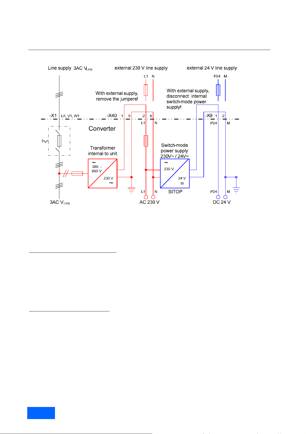
Fundamental Principles and System Description
Engineering Information
Supply of the auxiliaries with 230 V AC and of the electronics with 24 V. Example with a SINAMICS G150 cabinet unit.
The type of the SINAMICS Infeed (rectifier) determines the relationship between the supply voltage and the DC link
voltage. Further information on this can be found in the section “SINAMICS Infeeds (rectifiers) and their properties”.
The line-commutated, unregulated Infeeds
SINAMICS Basic Infeed and SINAMICS Smart Infeed generate a DC link
voltage, which is at stationary operation in proportion to the supp ly voltage. If the suppl y voltage di ps, the energ y flow
from the supply to the DC link is interrupted until the DC li nk voltage has, as a result of the load current, falle n to a
voltage level which corresponds to the supply voltage which has dipped. If this voltage level is below the undervoltage trip level of the DC link, the energy flo w from the supply to the DC link is completely interrupted. In this case
the drive can only use the electrical energy stored i n the DC link ca pacitors and c an only c ontinue to operate unti l the
DC link voltage has dropped to the value of the under-voltage trip level by means of the load curren t on the motor
side. This time span is in the range of a few milliseconds and depends on the load conditions of the drive. It
decreases as the load increases so that at full load, only small supply v oltage dips of a few milliseconds can be
overcome without fault tripping.
The self-commutated, regulated Infeed
, SINAMICS Active Infeed, operates as a step-up converter and can regulate
the DC link voltage, almost independently of the supply voltage, to a constant value. As a r esult, the energ y flow from
the supply to the DC link can also be ma intained during serious su pply voltage dips. As long as th e reduced power,
as a result of the lower supply voltage, can be compensated for by a higher input current, the drive is able to
overcome large and long supply voltage dips, without a fault trip.
The following pages will deal with the behaviour of the unregu lated and regulated SINAMICS Infeeds in view of the
above-mentioned considerations.
Permissible supply voltage dips with the unregulated SINAMICS Infeeds, Basic Infeed and Smart Infeed
In order to explain the behaviour of SINAMICS drives with line-commutated, unregulated Infeeds, all theoretically
possible supply voltage dips with regard to magnitude and duratio n are devided into six different range s, named A to
F. In the following diagram, these ranges are shown for unregulated SINAMICS Infeeds, whereby each range
corresponds to different boundary conditions and, therefore, to a different behaviour of the drive.
SINAMICS Engineering Manual – May 2008
28/396
Siemens AG
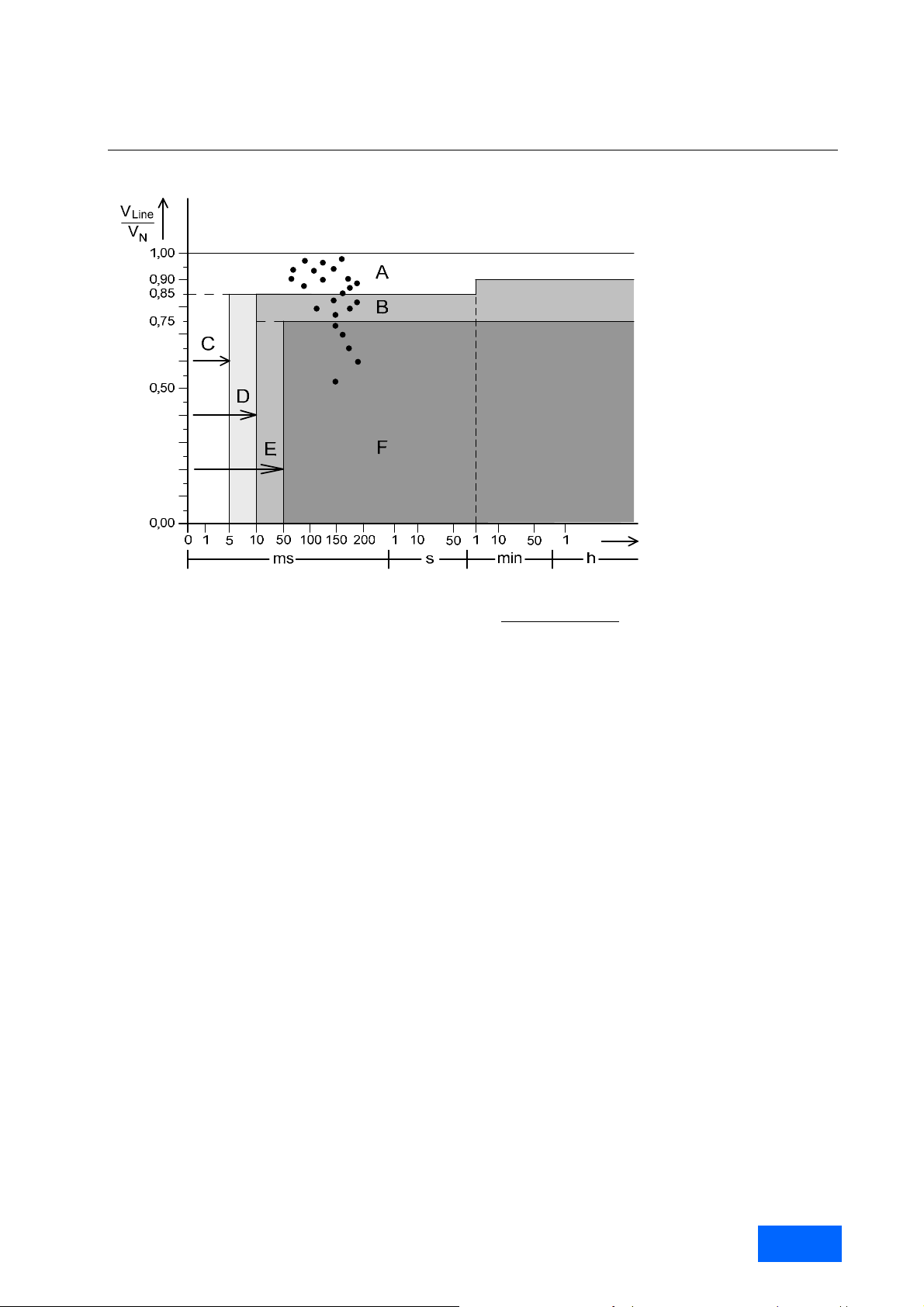
Fundamental Principles and System Description
Engineering Information
Division of all supply voltage dips according to magnitude and duration in the ranges
A - F for the description of the behaviour of SINAMICS drives with unregulated Infeeds
Range A
Range A comprises supply voltage dips, the magnitude of which is in the long and short-term ranges of permissible
supply voltage variations.
Dips in range A are, therefore, permissible, with the restriction that the DC link voltag e and the drive po wer decrease
in proportion to the magnitude of the supply voltage dips.
Range B
Range B comprises supply voltage dips, the magnitude of which reaches values of V
voltage which is in proportion to the supply v oltage is still over the under-voltage trip level in the DC link but the
auxiliaries which are supplied with 230 V by the internal transformer do not function any more after a few
milliseconds.
Dips in range B are, therefore, only permissible when the supply of the auxiliar ies with 230 V is done via a secure,
external source. It must also be taken into consideration t hat the DC link voltage and the drive power decrease in
proportion to the magnitude of the supply voltage dip.
Range C
Range C comprises very short supply voltage dips of an y magnitude, the duration of which is up to 5 ms. During this
time, the current required by the load is delivered entirel y by the D C link capacitors, thus causing the D C link voltage
to decrease. As a result of the extremely short duration of the dip, the DC link voltage still does not rea ch the undervoltage trip level, even at 100 % load. The auxiliaries supplied with 230 V also remain in operation.
Dips in range C are, therefore, as a result of the extremely short duration, permissible without restrictions.
Range D
Range D comprises very short supply voltage dips of any magnitude, the du ration of which is up to 10 ms. During this
time, the current required by the load is delivered entirel y by the D C link capacitors, thus causing the D C link voltage
to decrease. The DC link voltage then only does not reac h the under-voltage trip level, if the DC link is discharged
more slowly than in range C. Therefore, the drive can b e operated with a maximum load of appr ox. 50 %. Due to the
still relatively short duration, it can be assumed that the auxiliaries which are supplied with 230 V will remain in
operation.
Dips in range D are, therefore, as a result of the very short duration, permissible, as long as the drive is operating at
partial load with a maximum of 50 %.
≈ 0.75. The DC link
Line/VN
SINAMICS Engineering Manual - May 2008
Siemens AG
29/396
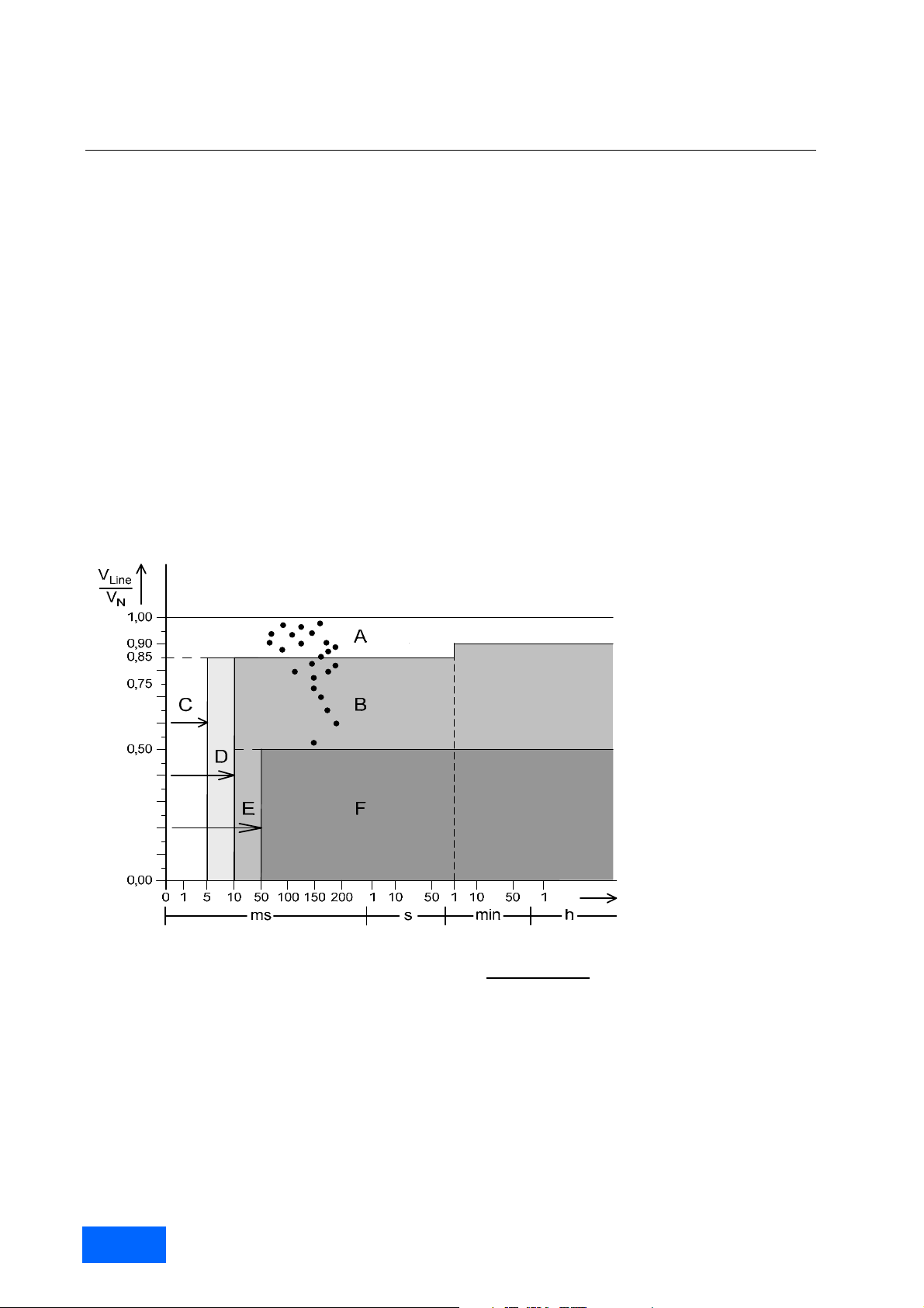
Fundamental Principles and System Description
Engineering Information
Range E
Range E comprises short supply voltage d ips of any magnitude, the duration of which is up to 50 ms. During this
time, the current required by the load is delivered entirely by the DC link capacitors, whereby the DC link voltage
decreases. The DC link voltage then only does not r each the under-voltage trip level, if the DC link is discharged
more slowly than in range D. Therefore, the drive can only be operated with no load. The auxiliaries, which are
supplied with 230 V directly from the supply via the internal transformer, do not remain in operation.
Dips in Range E are, therefore, only permissible if the au xiliaries are suppl ied from a secure, external supp ly and the
drive is in no-load operation.
Range F
Range F comprises supply voltage dips, the magnitude and duration of which is so large, that, independently of the
load, a fault trip due to under-voltage in the DC link cannot be avoided.
Dips in range F are, therefore, not permissible.
Permissible supply voltage dips with the regulated SINAMICS Active Infeed
In order to explain the behaviour of SINAMICS drives with self-commutated, regulated Infeeds, all theoretically
possible supply voltage dips with regard to magnitude and duration are divided into six, different ranges, named A to
F. In the following diagram, these ranges are shown for regulated SINAMICS Infeeds, whereby each range
corresponds to different boundary conditions and, therefore, to a different behaviour of the drive.
Division of all supply voltage dips according to magnitude and duration in the ranges
A to F for the description of the behaviour of SINAMICS drives with regulated Infeeds
Range A
Range A comprises supply voltage dips, the magnitude of which is in the long and short-term ranges of permissible
supply voltage variations.
Dips in range A are, therefore, permissible, with the restriction that the DC link voltag e and the drive po wer decrease
in proportion to the magnitude of the supply voltage dips.
Range B
Range B comprises supply voltage dips, the magnitude of which reaches values of V
≈ 0.5. As a result of the
Line/VN
regulated operation, the DC link voltage can be maintained at its pre-set value, as long as the red uced suppl y voltag e
can be compensated for with an increased input current. The auxiliaries supplied with 230 V via the internal
transformer, do not, however, remain in operation.
SINAMICS Engineering Manual – May 2008
30/396
Siemens AG
 Loading...